table of contents - southwest heater and control and brochures/watlow_controls_catalog.… · w a t...
TRANSCRIPT
W A T L O W
1
Cu
stom
er Assistan
ce
Table of Contents
Single-Loop ControllersAuto-Tuning PID
SERIES SD31 . . . . . . . . . . . . . . .27SERIES SD_C . . . . . . . . . . . . . . .29SERIES SD6C_D . . . . . . . . . . . .33SERIES 96 . . . . . . . . . . . . . . . . .35SERIES 988/989 . . . . . . . . . . . .39SERIES F4P . . . . . . . . . . . . . . . .45SERIES PD - Single Loop . . . . . .49MICRODIN® . . . . . . . . . . . . . . .53
On-OffSERIES CV . . . . . . . . . . . . . . . . .57SERIES CF . . . . . . . . . . . . . . . . .59SERIES 80M6 . . . . . . . . . . . . . . .61
PID with Time/Temperature ProfilingSERIES SD_R . . . . . . . . . . . . . . .63SERIES SD6R_D . . . . . . . . . . . . .67SERIES 96_AA . . . . . . . . . . . . . .69SERIES 981/982 . . . . . . . . . . . . .73SERIES F4S . . . . . . . . . . . . . . . .77
Limits/AlarmsSERIES LV . . . . . . . . . . . . . . . . .81SERIES LF . . . . . . . . . . . . . . . . .83SERIES SD_L . . . . . . . . . . . . . . .85SERIES SD6L_D . . . . . . . . . . . . .89SERIES 97 . . . . . . . . . . . . . . . . . .91
Temperature MeterSERIES TM . . . . . . . . . . . . . . . . .95
Customer Assistance
Temperature Controllers
Power Controllers Control Systems
Communication Gateways and Software
Single-Loop AccessoriesCurrent Transformers . . . . . . . . . . .97Adapter Plates . . . . . . . . . . . . . . . .97Noise Suppression Devices . . . . . .98
Multi-Loop ControllersAuto-Tuning PIDSERIES 998/999 . . . . . . . . . . . . . . .99SERIES PD - Dual Loop . . . . . . . .103CLS200 . . . . . . . . . . . . . . . . . . . .107MLS300 . . . . . . . . . . . . . . . . . . . .111SERIES D8 . . . . . . . . . . . . . . . . . .115PID with Time/Temperature ProfilingCLS200 . . . . . . . . . . . . . . . . . . . .119MLS300 . . . . . . . . . . . . . . . . . . . .123SERIES F4D . . . . . . . . . . . . . . . . .127SERIES N7 . . . . . . . . . . . . . . . . . .131MINICHEF® 2000 . . . . . . . . . . . . .135Limits/AlarmsTLM-8 . . . . . . . . . . . . . . . . . . . . .139CAS200 . . . . . . . . . . . . . . . . . . . .143PID with Programmable LogicCPC400 . . . . . . . . . . . . . . . . . . . .147PPC-2000 . . . . . . . . . . . . . . . . . .151Multi-Loop AccessoriesDAC/SDAC Modules . . . . . . . . . .159
DIN-A-MITE® . . . . . . . . . . . . . . . .161Style A . . . . . . . . . . . . . . . . . . .166Style B . . . . . . . . . . . . . . . . . . .167Style C . . . . . . . . . . . . . . . . . . .168Style D . . . . . . . . . . . . . . . . . . .171
SERIES CZR . . . . . . . . . . . . . . . .173POWER SERIES . . . . . . . . . . . . .175E-SAFE® RELAY . . . . . . . . . . . . .179Solid State Relays (SSRs) . . . . . .181QPAC SCRs . . . . . . . . . . . . . . . . .185Power Accessories . . . . . . . . . . .189
Communication GatewaysEM GATEWAY . . . . . . . . . . . . . . . .193CDN GATEWAY . . . . . . . . . . . . . .195SoftwareWATVIEW . . . . . . . . . . . . . . . . . . .197ANAWIN3® (PPC) . . . . . . . . . . . . .199WATCONNECT™ . . . . . . . . . . . . .200LOGICPRO™ . . . . . . . . . . . . . . . .201
Process Systems . . . . . . . . . . . . .203Control Panels . . . . . . . . . . . . . . .207Control Consoles . . . . . . . . . . . . .211Control Boxes . . . . . . . . . . . . . . .218Control Accessories . . . . . . . . . .221Controller OutputComparison Guide . . . . . . . . . . .225Temperature SensorRanges and Tolerances . . . . . . .228Think Safety . . . . . . . . . . . . . . . . .229Terms and Conditions . . . . . . . . .230
Custom Temperature andPower Controllers . . . . . . . . . . . . .2Systems Division . . . . . . . . . . . . .3Quick Reference Guide . . . . . . . . .4Manufacturing Facilities . . . . . . .23Sales Support Offices . . . . . . . . .24
Replacement SCRsand Diodes . . . . . . . . . . . . . . . . .189Current Transformers . . . . . . . . .189Noise Suppression Devices . . . .190CE Filters for DIN-A-MITEs . . . . .190DIN-Rail Mount Fuse Holders . . .191Semiconductor Fuses . . . . . . . . .191

2
CustomTemperature andPower ControllersYour CompleteSource For SolutionsWith ControlConfidence®
If the controllers contained in thiscatalog do not meet your applicationneeds, contact Watlow about acustom controller solution. Whetherthe application requires atemperature or power controller—ora complete, ready-to-install controlpanel—Watlow has the engineeringand manufacturing expertise tomake your application a reality.
But more than that, Watlow providesyou with a cooperative partnershipbased on service and ongoingproduct support. We have theexperience, stability and totalthermal system expertise to producethe controller that’s right for yourapplication.
Our Experience Includes:• Environmental chambers and
ovens
• Foodservice equipment
• Medical equipment
• Packaging
• Plastics
• Refrigerated transport
• Semiconductor
PartnershipsPartnership means providing thebest solution for your application;being there after the product isdelivered to make sure you receiveoptimum performance and value.Here is a brief overview of ourpartnering process:
1. Define specific application needs
2. Design the hardware package
3. Design the software
4. Refine order and meetspecifications and requirements
5. Deliver prototype
6. Review prototype for changes andrevisions; refine hardware andsoftware; produce and testchanges; deliver new prototype
7. Begin production and continuetesting
8. File product documentation; applyfor agency approvals; begin lineproduction
9. Provide ongoing product support
Advanced TechnologyWatlow offers the most modernengineering, testing and productionfacilities. Our focus on electronicsrequires a significant investment instate-of-the-art technology and ourengineers to continue theireducation in training programs thatkeep our personnel on the forefrontof innovation. This advantage isavailable to give your company’sproduct the competitive edge.
InnovationWatlow offers a diversity ofexperience. By serving manydifferent industries, we offer ablending of technologicalbackgrounds as well as anawareness of the latest in controllertechnology and advances. Watlow’sversatility means we’re not limited tothe conventions of any one industry.It’s easier for us to bring in better,innovative solutions.
AccountabilityWe assume full accountability formanaging the development processto a successful conclusion. Apartnership with Watlow means youcan devote your own resources toyour core competencies. We workwithin your time requirements andwe guarantee confidentiality andprotection of proprietary information.
Controller Manufacturing Involves:
Hardware Design• Microprocessor, analog and
discreet digital
• Surface mount technology
• Through-hole technology
• Qualification lab
• Electromagnetic compatibility
• Environmental testing
• Shock and vibration
• Agency approvals
Packaging Design• Mold design
• Mold tools
• Injection molding in plant
PC Board Design• Multi-layer
• Double-sided
Software Design• High level language for flexibility
and fast development
• Software demo design
• Communications
• Application overview screens
• Custom menus and functions
• Custom logic functions
• Custom communication protocols
Ask WatlowTo find out more about Watlow’scustom controller capability, contactyour local Watlow representativelisted on pages 24 and 25.

W A T L O W
3
Cu
stom
er Assistan
ce
Systems DivisionOutsourcing ThermalSystem Integration
Watlow has developed a newSystems Division to better serve theneeds of our customers. Watlow’sproduct focus on heaters, sensorsand controllers—the components ofa thermal system—has now beenexpanded. Now, Watlow can workwith the customer to design,manufacture, assemble, install andwarranty entire thermal systems.
• Utilizing Watlow componentsallows us to provide you with amore extensive total systemwarranty
• Watlow’s single-sourceresponsibility creates consistencythroughout every phase of theproject, maximizing synergybetween the design, manufacturing,assembly and installation
• Watlow is as flexible to your needsas required; select one service oran entire turnkey system:
• Prototyping, on-site pre-work andfield testing
• Optimizing existing thermal systems and creating retrofit plans
• Total system support, both hardware and software
• Providing design concepts
• Assisting in initial start-up
• Providing on-site troubleshooting
Services Offered
Watlow Systems Division offers thefollowing services:
Procurement
• Mechanical /electrical component• Strategic partnerships• Stocking
Design
• Optimizing existing thermal systems• Retrofit plans• Component interface• Package• Product tester• Standard system products• Mold designs• Thermal process design• Vacuum and injection mold design
Manufacturing
• ASME vessel fabrication • Skid fabrication• Standard products• Custom engineered products• Contract assembly• Supports remote warehousing• Remote manufacturing• Kitting of components
Technical support
• Total system support, bothhardware and software
• Prototyping, on-site pre-work andfield testing
• Support during the conceptualphase and design cycle
• On-site during start-up• On-site troubleshooting
Watlow Systems Division offers thefollowing capabilities:
• Axial and SMT assembly
Paste screening - product test
• PCB test and calibration
• Machining
General CNCPrecision machiningGun boring
• Welding and brazing
MIG, TIG and StickLaserVacuum
• Sheet metal fabrication
Aluminum and steel
Stainless steel and most alloys
• Finishing
Plating, anodizing, hard coatingSpecial coatingPainting and silk screening
• Agency approvals
• Plastic molding
• Metal casting
• Product testing/compliance
• System application expertise
• Purchasing/contracting
• Literature and documentationsupport
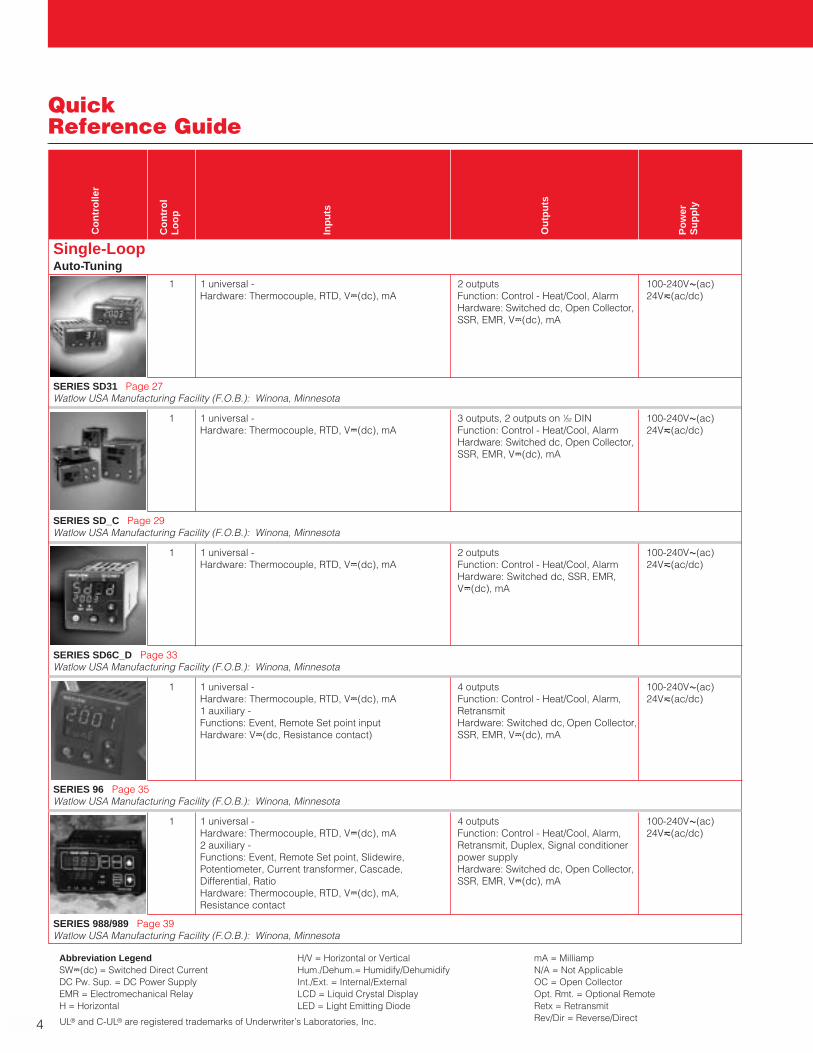
Single-LoopAuto-Tuning
1 1 universal - 2 outputs 100-240VÅ(ac)Hardware: Thermocouple, RTD, VÎ(dc), mA Function: Control - Heat/Cool, Alarm 24Vı(ac/dc)
Hardware: Switched dc, Open Collector,SSR, EMR, VÎ(dc), mA
SERIES SD31 Page 27Watlow USA Manufacturing Facility (F.O.B.): Winona, Minnesota
4
Quick Reference Guide
Co
ntr
olle
r
Co
ntr
ol
Lo
op
Inp
uts
Ou
tpu
ts
Po
wer
Su
pp
ly
1 1 universal - 3 outputs, 2 outputs on 1⁄32 DIN 100-240VÅ(ac)Hardware: Thermocouple, RTD, VÎ(dc), mA Function: Control - Heat/Cool, Alarm 24Vı(ac/dc)
Hardware: Switched dc, Open Collector,SSR, EMR, VÎ(dc), mA
SERIES SD_C Page 29Watlow USA Manufacturing Facility (F.O.B.): Winona, Minnesota
1 1 universal - 2 outputs 100-240VÅ(ac)Hardware: Thermocouple, RTD, VÎ(dc), mA Function: Control - Heat/Cool, Alarm 24Vı(ac/dc)
Hardware: Switched dc, SSR, EMR, VÎ(dc), mA
SERIES SD6C_D Page 33Watlow USA Manufacturing Facility (F.O.B.): Winona, Minnesota
1 1 universal - 4 outputs 100-240VÅ(ac)Hardware: Thermocouple, RTD, VÎ(dc), mA Function: Control - Heat/Cool, Alarm, 24Vı(ac/dc)1 auxiliary - Retransmit Functions: Event, Remote Set point input Hardware: Switched dc, Open Collector, Hardware: VÎ(dc, Resistance contact) SSR, EMR, VÎ(dc), mA
SERIES 96 Page 35Watlow USA Manufacturing Facility (F.O.B.): Winona, Minnesota
1 1 universal - 4 outputs 100-240VÅ(ac)Hardware: Thermocouple, RTD, VÎ(dc), mA Function: Control - Heat/Cool, Alarm, 24Vı(ac/dc)2 auxiliary - Retransmit, Duplex, Signal conditioner Functions: Event, Remote Set point, Slidewire, power supplyPotentiometer, Current transformer, Cascade, Hardware: Switched dc, Open Collector, Differential, Ratio SSR, EMR, VÎ(dc), mAHardware: Thermocouple, RTD, VÎ(dc), mA,Resistance contact
SERIES 988/989 Page 39Watlow USA Manufacturing Facility (F.O.B.): Winona, Minnesota
Abbreviation LegendSWÎ(dc) = Switched Direct CurrentDC Pw. Sup. = DC Power SupplyEMR = Electromechanical RelayH = Horizontal
H/V = Horizontal or VerticalHum./Dehum.= Humidify/DehumidifyInt./Ext. = Internal/ExternalLCD = Liquid Crystal DisplayLED = Light Emitting Diode
mA = MilliampN/A = Not ApplicableOC = Open CollectorOpt. Rmt. = Optional RemoteRetx = RetransmitRev/Dir = Reverse/DirectUL® and C-UL® are registered trademarks of Underwriter’s Laboratories, Inc.
W A T L O W
5
Cu
stom
er Assistan
ce
Quick Reference Guide
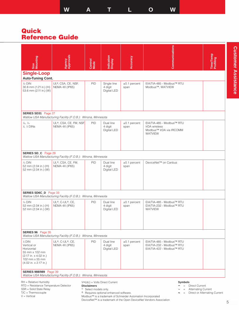
Single-LoopAuto-Tuning Cont.1⁄32 DIN UL®, CSA, CE, NSF, PID Single line ±0.1 percent EIA/TIA-485 - Modbus™ RTU30.8 mm (1.21 in.) (H) NEMA 4X (IP65) 4 digit span Modbus™, WATVIEW53.6 mm (2.11 in.) (W) Digital LED
SERIES SD31 Page 27Watlow USA Manufacturing Facility (F.O.B.): Winona, Minnesota
Siz
e M
ou
nti
ng
Ag
ency
Ap
pro
vals
Co
ntr
ol
Mo
de
Ind
icat
ion
Dis
pla
y
Acc
ura
cy
Co
mm
un
icat
ion
s
Tim
e/T
emp
Pro
filin
g
1⁄32, 1⁄16 UL®, CSA, CE, FM, NSF, PID Dual line ±0.1 percent EIA/TIA-485 - Modbus™ RTU1⁄8, 1⁄4 DINs NEMA 4X (IP65) 4 digit span IrDA wireless
Digital LED Modbus™ IrDA via IRCOMMWATVIEW
SERIES SD_C Page 29Watlow USA Manufacturing Facility (F.O.B.): Winona, Minnesota
1⁄16 DIN UL®, CSA, CE, FM, PID Dual line ±0.1 percent DeviceNet™ on Canbus52 mm (2.04 in.) (H) NEMA 4X (IP65) 4 digit span52 mm (2.04 in.) (W) Digital LED
SERIES SD6C_D Page 33Watlow USA Manufacturing Facility (F.O.B.): Winona, Minnesota
1⁄16 DIN UL®, C-UL®, CE, PID Dual line ±0.1 percent EIA/TIA-485 - Modbus™ RTU52 mm (2.04 in.) (H) NEMA 4X (IP65) 4 digit span EIA/TIA-232 - Modbus™ RTU52 mm (2.04 in.) (W) Digital LED WATVIEW
SERIES 96 Page 35Watlow USA Manufacturing Facility (F.O.B.): Winona, Minnesota
1⁄8 DIN UL®, C-UL®, CE, PID Dual line ±0.1 percent EIA/TIA-485 - Modbus™ RTUVertical or NEMA 4X (IP65) 4 digit span EIA/TIA-232 - Modbus™ RTUHorizontal Digital LED EIA/TIA-422 - Modbus™ RTU55 mm x 102 mm(2.17 in. x 4.02 in.)102 mm x 55 mm(4.02 in. x 2.17 in.)
SERIES 988/989 Page 39Watlow USA Manufacturing Facility (F.O.B.): Winona, Minnesota
RH = Relative HumidityRTD = Resistance Temperature DetectorSSR = Solid State RelayT/C = ThermocoupleV = Vertical
VÎ(dc) = Volts Direct CurrentDisclaimersa Select models only.b Requires optional enhanced software.Modbus™ is a trademark of Schneider Automation IncorporatedDeviceNet™ is a trademark of the Open DeviceNet Vendors Association
SymbolsÎ = Direct CurrentÅ = Alternating Currentı = Direct or Alternating Current
6
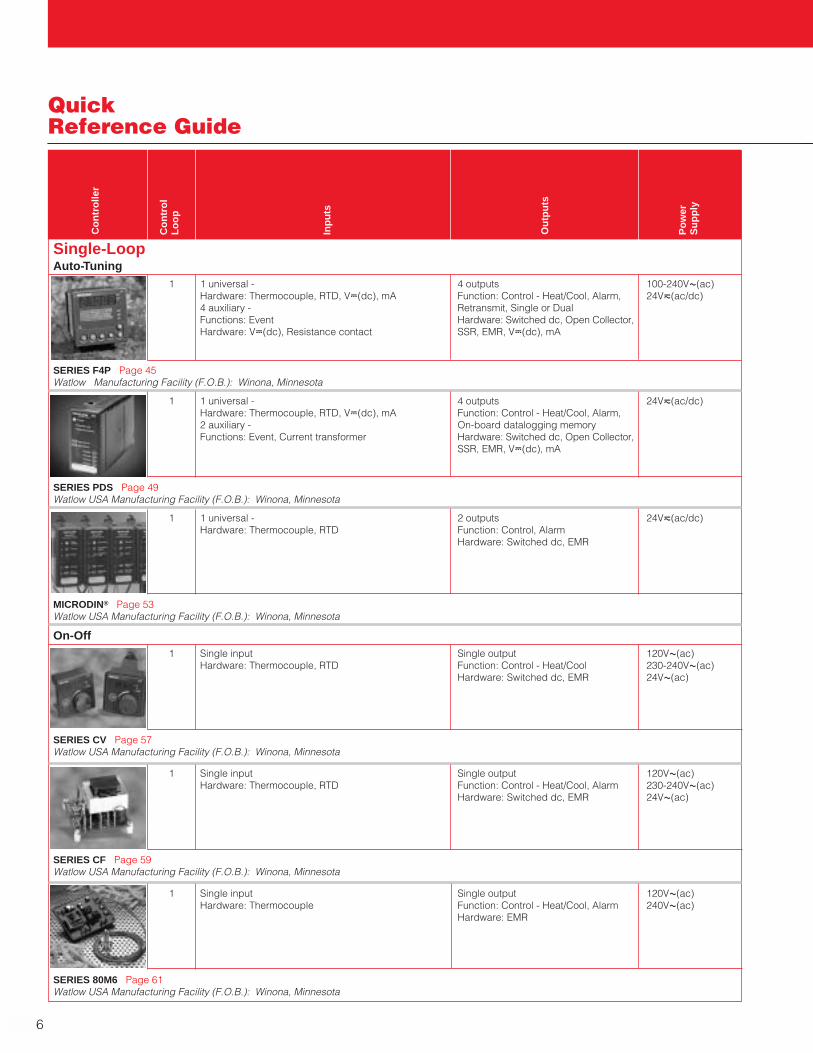
Single-LoopAuto-Tuning
1 1 universal - 4 outputs 100-240VÅ(ac)Hardware: Thermocouple, RTD, VÎ(dc), mA Function: Control - Heat/Cool, Alarm, 24Vı(ac/dc)4 auxiliary - Retransmit, Single or DualFunctions: Event Hardware: Switched dc, Open Collector,Hardware: VÎ(dc), Resistance contact SSR, EMR, VÎ(dc), mA
SERIES F4P Page 45Watlow Manufacturing Facility (F.O.B.): Winona, Minnesota
Quick Reference Guide
Co
ntr
olle
r
Co
ntr
ol
Lo
op
Inp
uts
Ou
tpu
ts
Po
wer
Su
pp
ly
1 1 universal - 4 outputs 24Vı(ac/dc)Hardware: Thermocouple, RTD, VÎ(dc), mA Function: Control - Heat/Cool, Alarm, 2 auxiliary - On-board datalogging memoryFunctions: Event, Current transformer Hardware: Switched dc, Open Collector,
SSR, EMR, VÎ(dc), mA
SERIES PDS Page 49Watlow USA Manufacturing Facility (F.O.B.): Winona, Minnesota
1 1 universal - 2 outputs 24Vı(ac/dc)Hardware: Thermocouple, RTD Function: Control, Alarm
Hardware: Switched dc, EMR
MICRODIN® Page 53Watlow USA Manufacturing Facility (F.O.B.): Winona, Minnesota
On-Off1 Single input Single output 120VÅ(ac)
Hardware: Thermocouple, RTD Function: Control - Heat/Cool 230-240VÅ(ac)Hardware: Switched dc, EMR 24VÅ(ac)
SERIES CV Page 57Watlow USA Manufacturing Facility (F.O.B.): Winona, Minnesota
1 Single input Single output 120VÅ(ac)Hardware: Thermocouple, RTD Function: Control - Heat/Cool, Alarm 230-240VÅ(ac)
Hardware: Switched dc, EMR 24VÅ(ac)
SERIES CF Page 59Watlow USA Manufacturing Facility (F.O.B.): Winona, Minnesota
1 Single input Single output 120VÅ(ac)Hardware: Thermocouple Function: Control - Heat/Cool, Alarm 240VÅ(ac)
Hardware: EMR
SERIES 80M6 Page 61Watlow USA Manufacturing Facility (F.O.B.): Winona, Minnesota
Cu
stom
er Assistan
ceW A T L O W
7
Quick Reference Guide
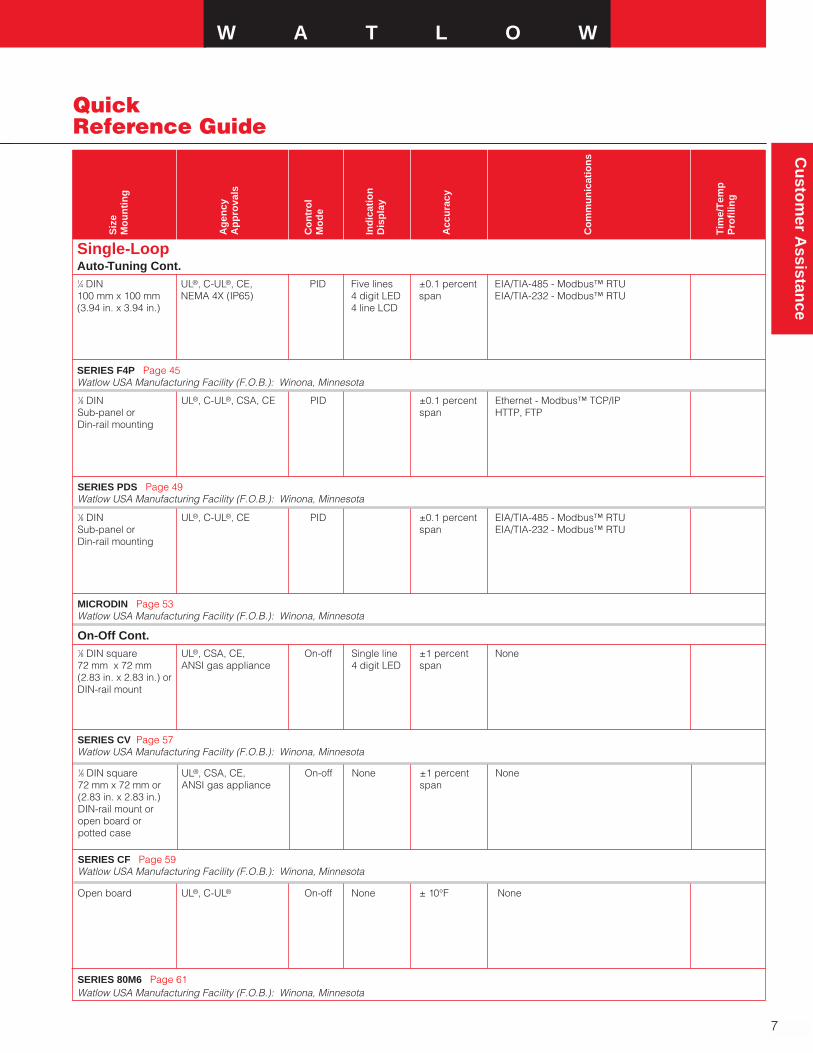
Single-LoopAuto-Tuning Cont.1⁄4 DIN UL®, C-UL®, CE, PID Five lines ±0.1 percent EIA/TIA-485 - Modbus™ RTU100 mm x 100 mm NEMA 4X (IP65) 4 digit LED span EIA/TIA-232 - Modbus™ RTU(3.94 in. x 3.94 in.) 4 line LCD
SERIES F4P Page 45Watlow USA Manufacturing Facility (F.O.B.): Winona, Minnesota
Siz
e M
ou
nti
ng
Ag
ency
Ap
pro
vals
Co
ntr
ol
Mo
de
Ind
icat
ion
Dis
pla
y
Acc
ura
cy
Co
mm
un
icat
ion
s
Tim
e/T
emp
Pro
filin
g
1⁄8 DIN UL®, C-UL®, CSA, CE PID ±0.1 percent Ethernet - Modbus™ TCP/IPSub-panel or span HTTP, FTPDin-rail mounting
SERIES PDS Page 49Watlow USA Manufacturing Facility (F.O.B.): Winona, Minnesota
1⁄8 DIN UL®, C-UL®, CE PID ±0.1 percent EIA/TIA-485 - Modbus™ RTUSub-panel or span EIA/TIA-232 - Modbus™ RTUDin-rail mounting
MICRODIN Page 53Watlow USA Manufacturing Facility (F.O.B.): Winona, Minnesota
On-Off Cont.1⁄8 DIN square UL®, CSA, CE, On-off Single line ±1 percent None72 mm x 72 mm ANSI gas appliance 4 digit LED span(2.83 in. x 2.83 in.) orDIN-rail mount
SERIES CV Page 57Watlow USA Manufacturing Facility (F.O.B.): Winona, Minnesota
1⁄8 DIN square UL®, CSA, CE, On-off None ±1 percent None72 mm x 72 mm or ANSI gas appliance span(2.83 in. x 2.83 in.)DIN-rail mount oropen board orpotted case
SERIES CF Page 59Watlow USA Manufacturing Facility (F.O.B.): Winona, Minnesota
Open board UL®, C-UL® On-off None ± 10°F None
SERIES 80M6 Page 61Watlow USA Manufacturing Facility (F.O.B.): Winona, Minnesota
8
Quick Reference Guide
Co
ntr
olle
r
Co
ntr
ol
Lo
op
Inp
uts
Ou
tpu
ts
Po
wer
Su
pp
ly
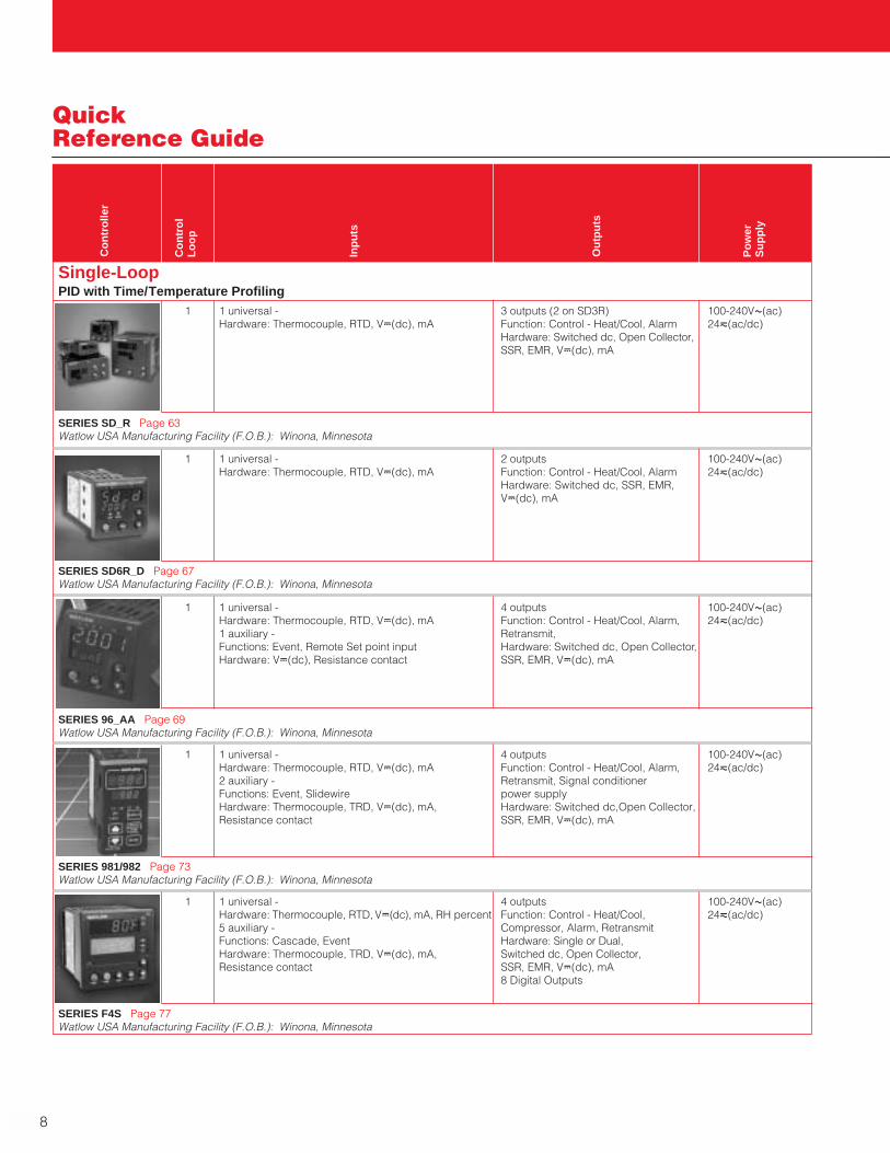
Single-LoopPID with Time/Temperature Profiling
1 1 universal - 3 outputs (2 on SD3R) 100-240VÅ(ac)Hardware: Thermocouple, RTD, VÎ(dc), mA Function: Control - Heat/Cool, Alarm 24ı(ac/dc)
Hardware: Switched dc, Open Collector,SSR, EMR, VÎ(dc), mA
SERIES SD_R Page 63Watlow USA Manufacturing Facility (F.O.B.): Winona, Minnesota
1 1 universal - 2 outputs 100-240VÅ(ac)Hardware: Thermocouple, RTD, VÎ(dc), mA Function: Control - Heat/Cool, Alarm 24ı(ac/dc)
Hardware: Switched dc, SSR, EMR, VÎ(dc), mA
SERIES SD6R_D Page 67Watlow USA Manufacturing Facility (F.O.B.): Winona, Minnesota
1 1 universal - 4 outputs 100-240VÅ(ac)Hardware: Thermocouple, RTD, VÎ(dc), mA Function: Control - Heat/Cool, Alarm, 24ı(ac/dc)1 auxiliary - Retransmit, Functions: Event, Remote Set point input Hardware: Switched dc, Open Collector, Hardware: VÎ(dc), Resistance contact SSR, EMR, VÎ(dc), mA
SERIES 96_AA Page 69Watlow USA Manufacturing Facility (F.O.B.): Winona, Minnesota
1 1 universal - 4 outputs 100-240VÅ(ac)Hardware: Thermocouple, RTD, VÎ(dc), mA Function: Control - Heat/Cool, Alarm, 24ı(ac/dc)2 auxiliary - Retransmit, Signal conditioner Functions: Event, Slidewire power supplyHardware: Thermocouple, TRD, VÎ(dc), mA, Hardware: Switched dc,Open Collector, Resistance contact SSR, EMR, VÎ(dc), mA
SERIES 981/982 Page 73Watlow USA Manufacturing Facility (F.O.B.): Winona, Minnesota
1 1 universal - 4 outputs 100-240VÅ(ac)Hardware: Thermocouple, RTD, VÎ(dc), mA, RH percent Function: Control - Heat/Cool, 24ı(ac/dc)5 auxiliary - Compressor, Alarm, RetransmitFunctions: Cascade, Event Hardware: Single or Dual,Hardware: Thermocouple, TRD, VÎ(dc), mA, Switched dc, Open Collector,Resistance contact SSR, EMR, VÎ(dc), mA
8 Digital Outputs
SERIES F4S Page 77Watlow USA Manufacturing Facility (F.O.B.): Winona, Minnesota
W A T L O W
9
Cu
stom
er Assistan
ce
Quick Reference Guide
Siz
e M
ou
nti
ng
Ag
ency
Ap
pro
vals
Co
ntr
ol
Mo
de
Ind
icat
ion
Dis
pla
y
Acc
ura
cy
Co
mm
un
icat
ion
s
Tim
e/T
emp
Pro
filin
g
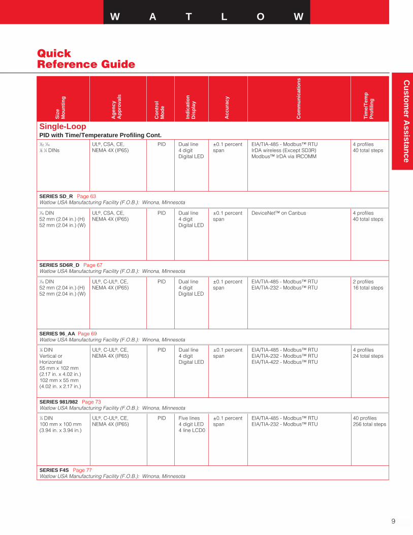
Single-LoopPID with Time/Temperature Profiling Cont.1⁄32,
1⁄16 UL®, CSA, CE, PID Dual line ±0.1 percent EIA/TIA-485 - Modbus™ RTU 4 profiles1⁄8,
1⁄4 DINs NEMA 4X (IP65) 4 digit span IrDA wireless (Except SD3R) 40 total stepsDigital LED Modbus™ IrDA via IRCOMM
SERIES SD_R Page 63Watlow USA Manufacturing Facility (F.O.B.): Winona, Minnesota
1⁄16 DIN UL®, CSA, CE, PID Dual line ±0.1 percent DeviceNet™ on Canbus 4 profiles52 mm (2.04 in.) (H) NEMA 4X (IP65) 4 digit span 40 total steps52 mm (2.04 in.) (W) Digital LED
SERIES SD6R_D Page 67Watlow USA Manufacturing Facility (F.O.B.): Winona, Minnesota
1⁄16 DIN UL®, C-UL®, CE, PID Dual line ±0.1 percent EIA/TIA-485 - Modbus™ RTU 2 profiles52 mm (2.04 in.) (H) NEMA 4X (IP65) 4 digit span EIA/TIA-232 - Modbus™ RTU 16 total steps52 mm (2.04 in.) (W) Digital LED
SERIES 96_AA Page 69Watlow USA Manufacturing Facility (F.O.B.): Winona, Minnesota
1⁄8 DIN UL®, C-UL®, CE, PID Dual line ±0.1 percent EIA/TIA-485 - Modbus™ RTU 4 profilesVertical or NEMA 4X (IP65) 4 digit span EIA/TIA-232 - Modbus™ RTU 24 total stepsHorizontal Digital LED EIA/TIA-422 - Modbus™ RTU55 mm x 102 mm(2.17 in. x 4.02 in.)102 mm x 55 mm(4.02 in. x 2.17 in.)
SERIES 981/982 Page 73Watlow USA Manufacturing Facility (F.O.B.): Winona, Minnesota
1⁄4 DIN UL®, C-UL®, CE, PID Five lines ±0.1 percent EIA/TIA-485 - Modbus™ RTU 40 profiles100 mm x 100 mm NEMA 4X (IP65) 4 digit LED span EIA/TIA-232 - Modbus™ RTU 256 total steps(3.94 in. x 3.94 in.) 4 line LCD0
SERIES F4S Page 77Watlow USA Manufacturing Facility (F.O.B.): Winona, Minnesota
10
Quick Reference Guide
Co
ntr
olle
r
Co
ntr
ol
Lo
op
Inp
uts
Ou
tpu
ts
Po
wer
Su
pp
ly
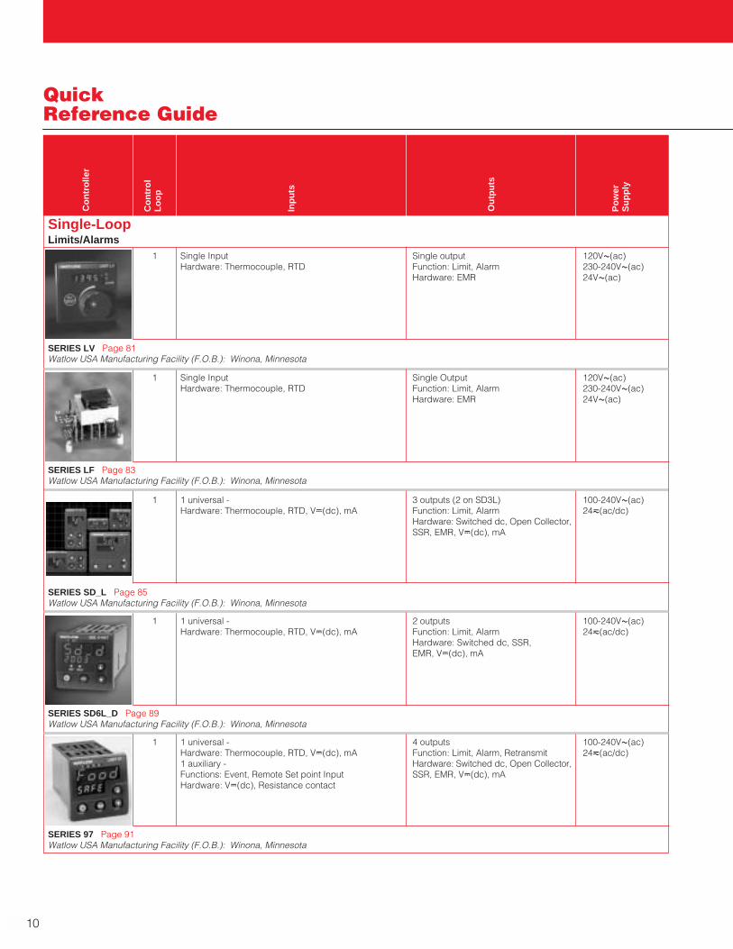
Single-LoopLimits/Alarms
1 Single Input Single output 120VÅ(ac)Hardware: Thermocouple, RTD Function: Limit, Alarm 230-240VÅ(ac)
Hardware: EMR 24VÅ(ac)
SERIES LV Page 81Watlow USA Manufacturing Facility (F.O.B.): Winona, Minnesota
1 Single Input Single Output 120VÅ(ac)Hardware: Thermocouple, RTD Function: Limit, Alarm 230-240VÅ(ac)
Hardware: EMR 24VÅ(ac)
SERIES LF Page 83Watlow USA Manufacturing Facility (F.O.B.): Winona, Minnesota
1 1 universal - 3 outputs (2 on SD3L) 100-240VÅ(ac)Hardware: Thermocouple, RTD, VÎ(dc), mA Function: Limit, Alarm 24ı(ac/dc)
Hardware: Switched dc, Open Collector,SSR, EMR, VÎ(dc), mA
SERIES SD_L Page 85Watlow USA Manufacturing Facility (F.O.B.): Winona, Minnesota
1 1 universal - 2 outputs 100-240VÅ(ac)Hardware: Thermocouple, RTD, VÎ(dc), mA Function: Limit, Alarm 24ı(ac/dc)
Hardware: Switched dc, SSR, EMR, VÎ(dc), mA
SERIES SD6L_D Page 89Watlow USA Manufacturing Facility (F.O.B.): Winona, Minnesota
1 1 universal - 4 outputs 100-240VÅ(ac)Hardware: Thermocouple, RTD, VÎ(dc), mA Function: Limit, Alarm, Retransmit 24ı(ac/dc)1 auxiliary - Hardware: Switched dc, Open Collector,Functions: Event, Remote Set point Input SSR, EMR, VÎ(dc), mAHardware: VÎ(dc), Resistance contact
SERIES 97 Page 91Watlow USA Manufacturing Facility (F.O.B.): Winona, Minnesota

Cu
stom
er Assistan
ceW A T L O W
11
Quick Reference Guide
Siz
e M
ou
nti
ng
Ag
ency
Ap
pro
vals
Co
ntr
ol
Mo
de
Ind
icat
ion
Dis
pla
y
Acc
ura
cy
Co
mm
un
icat
ion
s
Tim
e/T
emp
Pro
filin
g
Single-LoopLimits/Alarms Cont.1⁄8 DIN square FM, UL®, CSA, CE, High/low Single line ±1 percent None72 mm x 72 mm ANSI gas appliance, limit 4 digit LED span(2.83 in. x 2.83 in.) or DIN 3440DIN-rail mount
SERIES LV Page 81Watlow USA Manufacturing Facility (F.O.B.): Winona, Minnesota
1⁄8 DIN square FM, UL®, CSA, CE, High/low None ±1 percent None72 mm x 72 mm ANSI gas appliance, limit span(2.83 in. x 2.83 in.) DIN 3440DIN-rail mountor open board orpotted case
SERIES LF Page 83Watlow USA Manufacturing Facility (F.O.B.): Winona, Minnesota
1⁄32, 1⁄16 UL®, CSA, CE, FM, On-off Dual line ±0.1 percent EIA/TIA-485 - Modbus™ RTU1⁄8, 1⁄4 DINs NEMA 4X (IP65) 4 digit span IRDA wireless (except SD3L)
Digital LED Modbus™ IrDA via IRCOMM
SERIES SD_L Page 85Watlow USA Manufacturing Facility (F.O.B.): Winona, Minnesota
1⁄16 DIN UL®, CSA, CE, FM, On-off Dual line ±0.1 percent DeviceNet™ on Canbus52 mm (2.04 in.) (H) NEMA 4X (IP65) 4 digit span52 mm (2.04 in.) (W) Digital LED
SERIES SD6L_D Page 89Watlow USA Manufacturing Facility (F.O.B.): Winona, Minnesota
1⁄16 DIN FM, CE, On-off Dual line ±0.1 percent EIA/TIA-485 - Modbus™ RTU52 mm (2.04 in.) (H) NEMA 4X (IP65) 4 digit LED span EIA/TIA-232 - Modbus™ RTU52 mm (2.04 in.) (W) 4 line LCD0
SERIES 97 Page 91Watlow USA Manufacturing Facility (F.O.B.): Winona, Minnesota

12
Quick Reference Guide
Co
ntr
olle
r
Co
ntr
ol
Lo
op
Inp
uts
Ou
tpu
ts
Po
wer
Su
pp
ly
Single-LoopTemperature Meter
1 Single Input None - Indicator only 120VÅ(ac)Hardware: Thermocouple, RTD 230-240VÅ(ac)
24VÅ(ac)
SERIES TM Page 95Watlow USA Manufacturing Facility (F.O.B.): Winona, Minnesota
Communication GatewaysEthernet to EIA-485/232 Modbus™ RTU converter 24Vı(ac/dc)
Allows the following Modbus™ controllers to connect to Ethernet: SERIES SD, 96, 97,981/982, 998/999,F4, CLS200, POWER SERIES, MICRODIN
EM GATEWAY Page 193Watlow USA Manufacturing Facility (F.O.B.): Winona, Minnesota
1 DeviceNet™ to EIA-485/232 Modbus™ RTU converter 11-28VÎ(dc)
Allows the following Modbus™ controllers to connect to DeviceNet™: SERIES 96, 97, CLS200, MICRODIN
CDN GATEWAY Page 195Watlow USA Manufacturing Facility (F.O.B.): Winona, Minnesota
Multi-LoopAuto-Tuning PID
2 1 universal - 4 outputs 100-240VÅ(ac)Hardware: Thermocouple, RTD, VÎ(dc), mA Function: Control - Heat/Cool, Alarm, 24Vı(ac/dc)2 auxiliary - Retransmit, Signal conditioner Functions: RH percent, Event power supplyHardware: Thermocouple, RTD, VÎ(dc), mA, Hardware: Switched dc, Open Collector,
Differential, Ratio Resistance contact SSR, EMR, VÎ(dc), mA
SERIES 998/999 Page 99Watlow USA Manufacturing Facility (F.O.B.): Winona, Minnesota
2 2 universal 5 outputs 24Vı(ac/dc)Hardware: Thermocouple, RTD, VÎ(dc), mA Function: Control - Heat/Cool, Alarm, 2 auxiliary - Retransmit, On-board data logging Functions: Event, Current transformer memory
Hardware: Switched dc, Open Collector,SSR, EMR, VÎ(dc), mA
SERIES PDD Page 103Watlow USA Manufacturing Facility (F.O.B.): Winona, Minnesota
Cu
stom
er Assistan
ceW A T L O W
13
Quick Reference Guide
Siz
e M
ou
nti
ng
Ag
ency
Ap
pro
vals
Co
ntr
ol
Mo
de
Ind
icat
ion
Dis
pla
y
Acc
ura
cy
Co
mm
un
icat
ion
s
Tim
e/T
emp
Pro
filin
g
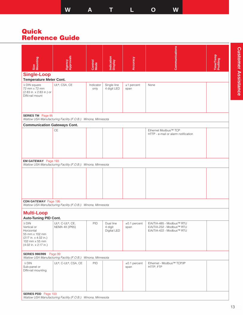
Single-LoopTemperature Meter Cont.1⁄8 DIN square UL®, CSA, CE Indicator Single line ±1 percent None72 mm x 72 mm only 4 digit LED span(2.83 in. x 2.83 in.) orDIN-rail mount
SERIES TM Page 95Watlow USA Manufacturing Facility (F.O.B.): Winona, Minnesota
Communication Gateways Cont.CE Ethernet Modbus™ TCP
HTTP - e-mail or alarm notification
EM GATEWAY Page 193Watlow USA Manufacturing Facility (F.O.B.): Winona, Minnesota
CDN GATEWAY Page 195Watlow USA Manufacturing Facility (F.O.B.): Winona, Minnesota
Multi-LoopAuto-Tuning PID Cont.1⁄8 DIN UL®, C-UL®, CE, PID Dual line ±0.1 percent EIA/TIA-485 - Modbus™ RTUVertical or NEMA 4X (IP65) 4 digit span EIA/TIA-232 - Modbus™ RTUHorizontal Digital LED EIA/TIA-422 - Modbus™ RTU55 mm x 102 mm(2.17 in. x 4.02 in.)102 mm x 55 mm(4.02 in. x 2.17 in.)
SERIES 998/999 Page 99Watlow USA Manufacturing Facility (F.O.B.): Winona, Minnesota
1⁄8 DIN UL®, C-UL®, CSA, CE PID ±0.1 percent Ethernet - Modbus™ TCP/IPSub-panel or span HTTP, FTPDIN-rail mounting
SERIES PDD Page 103Watlow USA Manufacturing Facility (F.O.B.): Winona, Minnesota
14
Quick Reference Guide
Co
ntr
olle
r
Co
ntr
ol
Lo
op
Inp
uts
Ou
tpu
ts
Po
wer
Su
pp
ly
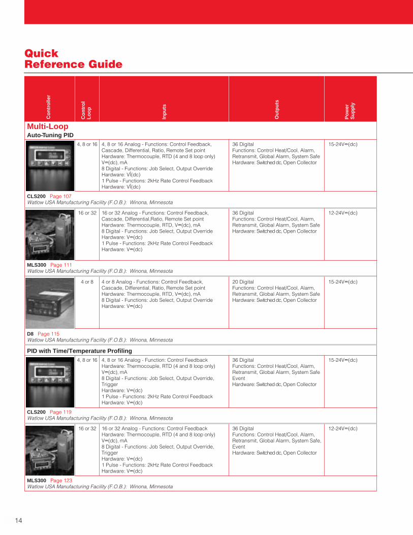
Multi-LoopAuto-Tuning PID
4, 8 or 16 4, 8 or 16 Analog - Functions: Control Feedback, 36 Digital 15-24VÎ(dc)Cascade, Differential, Ratio, Remote Set point Functions: Control Heat/Cool, Alarm,Hardware: Thermocouple, RTD (4 and 8 loop only) Retransmit, Global Alarm, System Safe VÎ(dc), mA Hardware: Switched dc, Open Collector8 Digital - Functions: Job Select, Output OverrideHardware: VÎ(dc)1 Pulse - Functions: 2kHz Rate Control FeedbackHardware: VÎ(dc)
CLS200 Page 107Watlow USA Manufacturing Facility (F.O.B.): Winona, Minnesota
16 or 32 16 or 32 Analog - Functions: Control Feedback, 36 Digital 12-24VÎ(dc)Cascade, Differential,Ratio, Remote Set point Functions: Control Heat/Cool, Alarm,Hardware: Thermocouple, RTD, VÎ(dc), mA Retransmit, Global Alarm, System Safe 8 Digital - Functions: Job Select, Output Override Hardware: Switched dc, Open CollectorHardware: VÎ(dc)1 Pulse - Functions: 2kHz Rate Control FeedbackHardware: VÎ(dc)
MLS300 Page 111Watlow USA Manufacturing Facility (F.O.B.): Winona, Minnesota
4 or 8 4 or 8 Analog - Functions: Control Feedback, 20 Digital 15-24VÎ(dc)Cascade, Differential, Ratio, Remote Set point Functions: Control Heat/Cool, Alarm,Hardware: Thermocouple, RTD, VÎ(dc), mA Retransmit, Global Alarm, System Safe 8 Digital - Functions: Job Select, Output Override Hardware: Switched dc, Open CollectorHardware: VÎ(dc)
D8 Page 115Watlow USA Manufacturing Facility (F.O.B.): Winona, Minnesota
PID with Time/Temperature Profiling4, 8 or 16 4, 8 or 16 Analog - Function: Control Feedback 36 Digital 15-24VÎ(dc)
Hardware: Thermocouple, RTD (4 and 8 loop only) Functions: Control Heat/Cool, Alarm,VÎ(dc), mA Retransmit, Global Alarm, System Safe 8 Digital - Functions: Job Select, Output Override, EventTrigger Hardware: Switched dc, Open CollectorHardware: VÎ(dc)1 Pulse - Functions: 2kHz Rate Control FeedbackHardware: VÎ(dc)
CLS200 Page 119Watlow USA Manufacturing Facility (F.O.B.): Winona, Minnesota
16 or 32 16 or 32 Analog - Functions: Control Feedback 36 Digital 12-24VÎ(dc)Hardware: Thermocouple, RTD (4 and 8 loop only) Functions: Control Heat/Cool, Alarm,VÎ(dc), mA Retransmit, Global Alarm, System Safe, 8 Digital - Functions: Job Select, Output Override, EventTrigger Hardware: Switched dc, Open CollectorHardware: VÎ(dc)1 Pulse - Functions: 2kHz Rate Control FeedbackHardware: VÎ(dc)
MLS300 Page 123Watlow USA Manufacturing Facility (F.O.B.): Winona, Minnesota
Cu
stom
er Assistan
ceW A T L O W
15
Quick Reference Guide
Siz
e M
ou
nti
ng
Ag
ency
Ap
pro
vals
Co
ntr
ol
Mo
de
Ind
icat
ion
Dis
pla
y
Acc
ura
cy
Co
mm
un
icat
ion
s
Tim
e/T
emp
Pro
filin
g
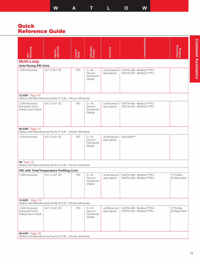
Multi-LoopAuto-Tuning PID Cont.1⁄8 DIN Horizontal UL®, C-UL®, CE PID 2 x 16 ±0.08 percent EIA/TIA-485 - Modbus™ RTU
Vacuum span typical EIA/TIA-232 - Modbus™ RTUFluorescentDisplay
CLS200 Page 107Watlow USA Manufacturing Facility (F.O.B.): Winona, Minnesota
1⁄8 DIN Horizontal UL®, C-UL®, CE PID 2 x 16 ±0.08 percent EIA/TIA-485 - Modbus™ RTUSub-panel mount Vacuum span typical EIA/TIA-232 - Modbus™ RTUanalog input module Fluorescent
Display
MLS300 Page 111Watlow USA Manufacturing Facility (F.O.B.): Winona, Minnesota
1⁄8 DIN Horizontal UL®, C-UL®, CE PID 2 x 16 ±0.08 percent DeviceNet™Vacuum span typicalFluorescentDisplay
D8 Page 115Watlow USA Manufacturing Facility (F.O.B.): Winona, Minnesota
PID with Time/Temperature Profiling Cont.1⁄8 DIN Horizontal UL®, C-UL®, CE PID 2 x 16 ±0.08 percent EIA/TIA-485 - Modbus™ RTU 17 Profiles
Vacuum span typical EIA/TIA-232 - Modbus™ RTU 20 Steps EachFluorescentDisplay
CLS200 Page 119Watlow USA Manufacturing Facility (F.O.B.): Winona, Minnesota
1⁄8 DIN Horizontal UL®, C-UL®, CE PID 2 x 16 ±0.08 percent EIA/TIA-485 - Modbus™ RTU 17 ProfilesSub-panel mount Vacuum span typical EIA/TIA-232 - Modbus™ RTU 20 Steps Eachanalog input module Fluorescent
Display
MLS300 Page 123Watlow USA Manufacturing Facility (F.O.B.): Winona, Minnesota
16
Quick Reference Guide
Co
ntr
olle
r
Co
ntr
ol
Lo
op
Inp
uts
Ou
tpu
ts
Po
wer
Su
pp
ly
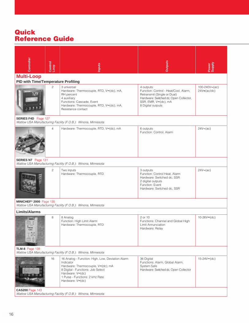
Multi-LoopPID with Time/Temperature Profiling
2 3 universal 4 outputs 100-240VÅ(ac)Hardware: Thermocouple, RTD, VÎ(dc), mA, Function: Control - Heat/Cool, Alarm, 24Vı(ac/dc)RH percent Retransmit (Single or Dual)4 auxiliary Hardware: Switched dc, Open Collector,Functions: Cascade, Event SSR, EMR, VÎ(dc), mAHardware: Thermocouple, RTD, VÎ(dc), mA, 8 Digital outputsResistance contact
SERIES F4D Page 127Watlow USA Manufacturing Facility (F.O.B.): Winona, Minnesota
4 Hardware: Thermocouple, RTD, VÎ(dc), mA 6 outputs 24VÅ(ac)Function: Control, Alarm
SERIES N7 Page 131Watlow USA Manufacturing Facility (F.O.B.): Winona, Minnesota
2 Two inputs 3 outputs 24VÅ(ac)Hardware: Thermocouple, RTD Function: Control Heat, Alarm
Hardware: Switched dc, SSR2 digital outputsFunction: EventHardware: Switched dc, SSR
MINICHEF® 2000 Page 135Watlow USA Manufacturing Facility (F.O.B.): Winona, Minnesota
Limits/Alarms8 8 Analog 2 or 10 10-26VÎ(dc)
Function: High Limit Alarm Functions: Channel and Global HighHardware: Thermocouple, RTD Limit Annunciation
Hardware: Relay
TLM-8 Page 139Watlow USA Manufacturing Facility (F.O.B.): Winona, Minnesota
16 16 Analog - Function: High, Low, Deviation Alarm 36 Digital 15-24VÎ(dc)Indicator Functions: Alarm, Global Alarm,Hardware: Thermocouple, VÎ(dc), mA System Safe8 Digital - Functions: Job Select Hardware: Switched dc, Open CollectorHardware: VÎ(dc)1 Pulse - Functions: 2 kHz RateHardware: VÎ(dc)
CAS200 Page 143Watlow USA Manufacturing Facility (F.O.B.): Winona, Minnesota

Cu
stom
er Assistan
ceW A T L O W
17
Quick Reference Guide
Siz
e M
ou
nti
ng
Ag
ency
Ap
pro
vals
Co
ntr
ol
Mo
de
Ind
icat
ion
Dis
pla
y
Acc
ura
cy
Co
mm
un
icat
ion
s
Tim
e/T
emp
Pro
filin
g
Multi-LoopPID with Time/Temperature Profiling Cont.1⁄4 DIN UL®, C-UL®, CE, PID Five lines ±0.1 percent EIA/TIA-485 - Modbus™ RTU 40 profiles100 mm x 100 mm NEMA 4X (IP65) 5 digit LED span EIA/TIA-232 - Modbus™ RTU 256 total steps(3.94 in. x 3.94 in.) 4 line LCD
SERIES F4D Page 127Watlow USA Manufacturing Facility (F.O.B.): Winona, Minnesota
Flush mount UL®, C-UL®, CSA, CE, PID Dual line 1.1°C Ethernet - NAFEM protocolNSF, NAFEM data 4 digit EIA/TIA-485 - Modbus™ RTUprotocol communications 7 segment EIA/TIA-232 - Modbus™ RTU
LED8 digitalphanumeric
SERIES N7 Page 131Watlow USA Manufacturing Facility (F.O.B.): Winona, Minnesota
Flush mount UL®, C-UL®, CSA, CE, PID Single line ±0.35 percentNSF, AGA 5 digit LED span
MINICHEF 2000 Page 135Watlow USA Manufacturing Facility (F.O.B.): Winona, Minnesota
Limits/Alarms Cont.DIN-rail or Fastener UL®, C-UL®, CE, FM On-off ±5 percentSub-panel mount or 1 percent
of trip point
TLM-8 Page 139Watlow USA Manufacturing Facility (F.O.B.): Winona, Minnesota
1⁄8 DIN Horizontal UL®, C-UL®, CE On-off 2 x 16 ±0.08 percent EIA/TIA-485 - Modbus™ RTUVacuum span typical EIA/TIA-232 - Modbus™ RTUFluorescentDisplay
CAS200 Page 143Watlow USA Manufacturing Facility (F.O.B.): Winona, Minnesota
18
Quick Reference Guide
Co
ntr
olle
r
Co
ntr
ol
Lo
op
Inp
uts
Ou
tpu
ts
Po
wer
Su
pp
ly
Multi-LoopPID with Programmable Logic
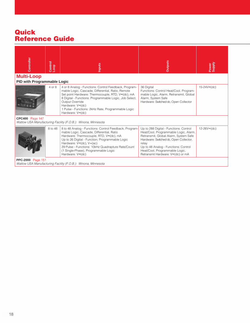
4 or 8 4 or 8 Analog - Functions: Control Feedback, Program- 36 Digital 15-24VÎ(dc)mable Logic, Cascade, Differential, Ratio, Remote Functions: Control Heat/Cool, Program- Set point Hardware: Thermocouple, RTD, VÎ(dc), mA mable Logic, Alarm, Retransmit, Global8 Digital - Functions: Programmable Logic, Job Select, Alarm, System SafeOutput Override Hardware: Switched dc, Open CollectorHardware: VÎ(dc)1 Pulse - Functions: 2kHz Rate, Programmable LogicHardware: VÎ(dc)
CPC400 Page 147Watlow USA Manufacturing Facility (F.O.B.): Winona, Minnesota
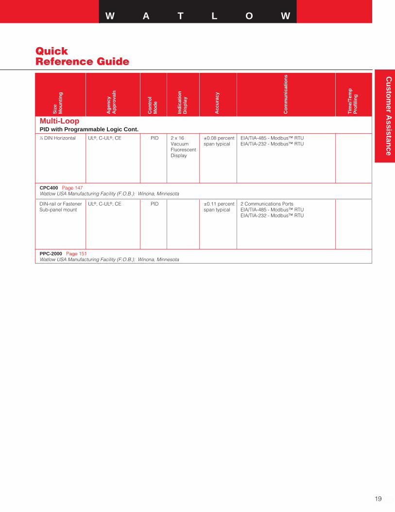
8 to 48 8 to 48 Analog - Functions: Control Feedback, Program- Up to 288 Digital - Functions: Control 12-26VÎ(dc)mable Logic, Cascade, Differential, Ratio Heat/Cool, Programmable Logic, Alarm,Hardware: Thermocouple, RTD, VÎ(dc), mA Retransmit, Global Alarm, System SafeUp to 26 Digital - Function; Programmable Logic Hardware: Switched dc, Open Collector,Hardware: VÎ(dc), VÅ(ac) relay29 Pulse - Functions: 10kHz Quadrapture Rate/Count Up to 48 Analog - Functions: Control(1 Single-Phase), Programmable Logic Heat/Cool, Programmable Logic,Hardware: VÎ(dc) Retransmit Hardware: VÎ(dc) or mA
PPC-2000 Page 151Watlow USA Manufacturing Facility (F.O.B.): Winona, Minnesota
W A T L O W
19
Cu
stom
er Assistan
ce
Quick Reference Guide
Siz
e M
ou
nti
ng
Ag
ency
Ap
pro
vals
Co
ntr
ol
Mo
de
Ind
icat
ion
Dis
pla
y
Acc
ura
cy
Co
mm
un
icat
ion
s
Tim
e/T
emp
Pro
filin
g
Multi-LoopPID with Programmable Logic Cont.1⁄8 DIN Horizontal UL®, C-UL®, CE PID 2 x 16 ±0.08 percent EIA/TIA-485 - Modbus™ RTU
Vacuum span typical EIA/TIA-232 - Modbus™ RTUFluorescentDisplay
CPC400 Page 147Watlow USA Manufacturing Facility (F.O.B.): Winona, Minnesota
DIN-rail or Fastener UL®, C-UL®, CE PID ±0.11 percent 2 Communications PortsSub-panel mount span typical EIA/TIA-485 - Modbus™ RTU
EIA/TIA-232 - Modbus™ RTU
PPC-2000 Page 151Watlow USA Manufacturing Facility (F.O.B.): Winona, Minnesota
Quick Reference Guide
Co
ntr
olle
r
Max
imu
mC
urr
ent
Ph
ase
Inp
uts
Ou
tpu
t/F
eatu
res
Mo
de
Mo
un
tin
g
Ag
ency
Ap
pro
vals
Op
erat
ing
En
viro
nm
ent
20
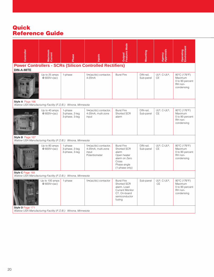
Up to 40 amps 1-phase Vı(ac/dc) contactor, Burst Fire DIN-rail, UL®, C-UL®, 80°C (176°F)@ 600VÅ(ac) 3-phase, 2-leg 4-20mA, multi-zone Shorted SCR Sub-panel CE Maximum
3-phase, 3-leg input alarm 0 to 90 percentRH non-condensing
Style B Page 167Watlow USA Manufacturing Facility (F.O.B.): Winona, Minnesota
Up to 80 amps 1-phase Vı(ac/dc) contactor, Burst Fire DIN-rail, UL®, C-UL®, 80°C (176°F)@ 600VÅ(ac) 3-phase, 2-leg 4-20mA, multi-zone Shorted SCR Sub-panel CE Maximum
3-phase, 3-leg input alarm 0 to 90 percentPotentiometer Open heater RH non-
alarm on Zero condensingCrossPhase-angle(1-phase only)
Style C Page 168Watlow USA Manufacturing Facility (F.O.B.): Winona, Minnesota
Power Controllers - SCRs (Silicon Controlled Rectifiers)DIN-A-MITE
Up to 25 amps 1-phase Vı(ac/dc) contactor, Burst Fire DIN-rail, UL®, C-UL®, 80°C (176°F)@ 600VÅ(ac) 4-20mA Sub-panel CE Maximum
0 to 90 percentRH non-condensing
Style A Page 166Watlow USA Manufacturing Facility (F.O.B.): Winona, Minnesota
Up to 100 amps 1-phase Vı(ac/dc) contactor Burst Fire Sub-panel UL®, C-UL®, 80°C (176°F)@ 600VÅ(ac) Shorted SCR CE Maximum
alarm, Load 0 to 90 percentCurrent Monitor RH non-CT, On-board condensingsemiconductorfusing
Style D Page 171Watlow USA Manufacturing Facility (F.O.B.): Winona, Minnesota
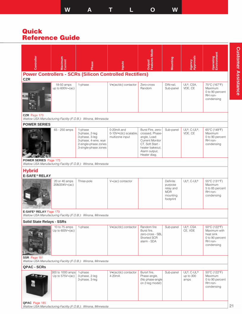
QPAC - SCRs300 to 1000 amps 1-phase Vı(ac/dc) contactor Bursrt fire, Sub-panel UL®, C-UL® 50°C (122°F)Up to 575VÅ(ac) 3-phase, 2-leg 4-20mA Phase-angle, up to 300 Maximum
3-phase, 3-leg (No phase-angle amps 0 to 90 percenton 2-leg model) RH non-
condensing
QPAC Page 185Watlow USA Manufacturing Facility (F.O.B.): Winona, Minnesota
W A T L O W
21
Cu
stom
er Assistan
ce
Quick Reference Guide
Co
ntr
olle
r
Max
imu
mC
urr
ent
Ph
ase
Inp
uts
Ou
tpu
t/F
eatu
res
Mo
de
POWER SERIES65 - 250 amps 1-phase 0-20mA and Burst Fire, zero- Sub-panel UL®, C-UL®, 65°C (149°F)
3-phase, 2-leg 0-10VÎ(dc) scalable, crossed, Phase- VDE, CE Maximum3-phase, 3-leg multizone input angle, Load 0 to 90 percent3-phase, 4-wire, wye Current Monitor RH non-2-single-phase zones CT, Soft Start - condensing3-single-phase zones heater bakeout,
Alarm output,Heater diag.
POWER SERIES Page 175Watlow USA Manufacturing Facility (F.O.B.): Winona, Minnesota
Power Controllers - SCRs (Silicon Controlled Rectifiers)CZR
18-50 amps 1-phase Vı(ac/dc) contactor Zero-cross DIN-rail, UL®, CSA, 75°C (167°F)up to 600VÅ(ac) Random Sub-panel VDE, CE Maximum
0 to 90 percentRH non-condensing
CZR Page 173Watlow USA Manufacturing Facility (F.O.B.): Winona, Minnesota
Solid State Relays - SSRs10 to 75 amps 1-phase Vı(ac/dc) contactor Random fire Sub-panel UL®, CSA 50°C (122°F)
Up to 600VÅ(ac) Burst fire, CE, VDE Maximum withzero-cross - SBL heat sinkShorted SCR 0 to 90 percentalarm - SDA RH non-
condensing
SSR Page 181Watlow USA Manufacturing Facility (F.O.B.): Winona, Minnesota
HybridE-SAFE® RELAY
20 or 40 amps Three-pole VÅ(ac) contactor Definite UL®, C-UL® 55°C (131°F)208/204VÅ(ac) purpose Maximum
relay and 5 to 85 percentMDR RH non-mounting condensingfootprint
E-SAFE® RELAY Page 179Watlow USA Manufacturing Facility (F.O.B.): Winona, Minnesota
Mo
un
tin
g
Ag
ency
Ap
pro
vals
Op
erat
ing
En
viro
nm
ent

22
CustomerAssistance
ReplacementControllers
SERIES 93 SERIES SD6C 29
SERIES 94 SERIES SD6L 85
SERIES 935 SERIES SD31 or SD3C 27 or 29
SERIES 945 SERIES SD_C 29
SERIES 988LF SERIES SD_C 29
SERIES 101 SERIES CV 57
SERIES 102 SERIES CV 57
SERIES 103 SERIES CV 57
SERIES 104 SERIES CV or SERIES CF 57 or 59
SERIES 942 SERIES 96_AA or SERIES SD4R 69 or 63
SERIES 142 SERIES LV or SERIES LF 81 or 83
SERIES 145 SERIES LV 81
SERIES 146 SERIES LV 81
SERIES 147 SERIES LV or SERIES LF 81 or 83
SERIES 550 SERIES TM 95
SERIES 733/734 SERIES N7 131
MDR E-SAFE® RELAY 179
Existing Controller Suggested New Replacement Page
W A T L O W
23
Cu
stom
er Assistan
ce
WatlowManufacturingFacilitiesUnited States ManufacturingFacilities
Anaheim, CaliforniaWatlow AOV, Inc.Manufactures:• Silicone Rubber Heaters1400 North Kellogg Drive, Suite AAnaheim, CA 92807
Phone: 714-779-2252FAX: 714-777-9626
Batavia, IllinoisWatlow BataviaManufactures:• Cast-In Heaters
1310 Kingsland DriveBatavia, IL 60510
Phone: 630-879-2696FAX #1: 630-879-1101FAX #2: 630-482-2042
Chesterfield, MissouriWatlow EngineeringManufactures:• Machines
636 Goddard AvenueChesterfield, MO 63005
Phone: 636-530-0288Fax: 636-530-0395
Columbia, MissouriWatlow Columbia/Ceramic FiberManufactures:• Ceramic Fiber Heaters
2407 Big Bear CourtColumbia, MO 65202
Phone: 573-443-8817FAX: 573-443-8818
Watlow Columbia/FlexibleManufactures:• Flexible Heaters
2101 Pennsylvania DriveColumbia, MO 65202
Phone: 573-474-9402FAX: 573-474-5859
Fenton, MissouriSingle IterationA Consulting Services Division of Watlow
909 Horan DriveFenton, MO 63026
Phone: 866-449-6846FAX: 636-349-5352
Hannibal, MissouriWatlow HannibalManufactures:• Circulation Heaters• Duct Heaters• Immersion Heaters• Multicell Heaters• Tubular Heaters• Thick Film Heaters
#6 Industrial Loop RoadP.O. Box 975Hannibal, MO 63401
Phone: 573-221-2816FAX: Tubular/Process/Multicell
573-221-3723FAX: Thick Film
573-221-7578
Richmond, IllinoisWatlow RichmondManufactures:• RTDs, Thermocouples, Thermistors• Thermocouple Wire and Cable• Temperature Measurement Devices
5710 Kenosha Street, P.O. Box 500Richmond, IL 60071
Phone: 815-678-2211FAX: 815-678-3961
St. Louis, MissouriWorld Headquarters and Watlow St. LouisManufactures:• Band Heaters• Cable Heaters• FIREROD® Heaters• Radiant Heaters• Special Heaters• Strip Heaters
12001 Lackland RoadSt. Louis, MO 63146
Phone: 314-878-4600FAX: 314-878-6814
Watsonville, CaliforniaWatlow AnafazeManufactures:• Multi-Loop Controls• High Level Software
Phone: 507-454-5300FAX: 507-452-4507
Winona, Minnesota - ControllersWatlow Winona, Inc.Manufactures:• Custom Electronic Controllers• Power Controllers• Safety and Limit Controllers• Single-Loop Controllers
1241 Bundy Boulevard, P.O. Box 5580Winona, MN 55987-5580
Phone: 507-454-5300FAX: 507-452-4507
Winona, Minnesota - PolymerWatlow Polymer Technologies, Inc.Manufactures:• Polymer Heaters
1265 East Sanborn StreetWinona, MN 55987
Phone: 507-457-9797FAX: 507-457-9736
Wright City, MissouriWatlow Process SystemsManufactures:• Process Heating Systems
#10 Cooperative WayWright City, Missouri 63390
Phone: 636-745-7575FAX: 636-745-0537
Asian Manufacturing Facilities
Singapore
Watlow Asia EngineeringManufactures:• FIREROD Heaters• Thermocouples• Pump Line Heaters• Controllers• Power Controllers
16 Ayer Rajah Crescent, #03-23Singapore 139949
Phone: +65-6777-1266FAX: +65-6777-7662
CustomerAssistance
24
CustomerAssistanceWatlowManufacturingFacilitiesEuropean Manufacturing Facilities
GermanyWatlow GmbHManufactures:• Cable Heaters• Cartridge Heaters
(FIREROD, EB Cartridge andMetric FIREROD)
• Silicone Rubber Heaters• K-RING® Heaters• Pump Line Heaters• Electronic Assemblies
Lauchwasenstr. 1Postfach 1165D 76709 Kronau, Germany
Phone: +49-7253-94-00-0FAX: +49-7253-94-00-44
ItalyWatlow Italy, S.r.l.Manufactures:• Thermocouples
Via Meucci 1420094 Corsico - MI, Italy
Phone: +39-02-4588841FAX: +39-02-45869954
United KingdomWatlow LimitedManufactures:• Band Heaters• Cartridge Heaters• FIREROD Heaters• Silicone Rubber Heaters• Thermocouples
Robey CloseLinby Industrial EstateLinby, Nottingham, England NG15 8AA
Phone: +44-0-115-964-0777FAX: +44-0-115-964-0071
Latin American ManufacturingFacilities
MexicoWatlow de Mexico, S.A. de C.V.Manufactures:• FIREROD Heaters
(Cartridge and Metric)• Ceramic Knuckle Heaters• THINBAND® Heaters• HV Band Heaters• Silicone Rubber Heaters• Tubular Heaters• Cable Heaters
Av. Epigmenio Gonzalez No. 5Col. Parques IndustrialesQuerétaro C.P. 76130Querétaro, Mexico
Phone: +52-442-217-62-35Fax: +52-442-217-64-03
Sales SupportUnited States Sales Offices
Atlanta
1320 Highland Lake DriveLawrenceville, GA 30045-8225
Phone: 770-972-4948Fax: 770-972-5138
Austin
12343 Hymeadow, Suite 2IAustin, TX 78750-1830
Phone: 512-249-1900Fax: 512-249-0082
Birmingham
308 Honeysuckle LaneChelsea, AL 35043-9669
Phone: 205-678-2358Fax: 205-678-2567
Charlotte
10915 Tara Oaks DriveCharlotte, NC 28227-5493
Phone: 704-573-8446Fax: 866-422-5998
Chicago
1320 Chase Street, Suite 2Algonquin, IL 60102-9668
Phone: 847-458-1500Fax: 847-458-1515
Cincinnati
4700 Duke Drive, Suite 125Mason, OH 45040-9379
Phone: 513-398-5500Fax: 513-398-7575
Cleveland
28 West Aurora RoadNorthfield, OH 44067-2063
Phone: 330-467-1423Fax: 330-467-1659
Dallas
609 Storrs St.Rockwall, TX 75087
Phone: 972-620-6030Fax: 972-620-8620
Denver
5945 West Sumac AvenueLittleton, CO 80123-0886
Phone: 303-798-7778Fax: 303-798-7775

W A T L O W
25
Cu
stom
er Assistan
ce
Sales SupportUnited States Sales Offices Cont.
Detroit
155 Romeo Road, Suite 600Rochester, MI 48307-1580
Phone: 248-651-0500Fax: 248-651-6164
Houston
3403 Chapel Square DriveSpring, TX 77388-5160
Phone: 281-440-3074Fax: 281-440-6873
Indianapolis
160 W. Carmel Drive, Suite 204Carmel, IN 46032-4745
Phone: 317-575-8932Fax: 317-575-9478
Kansas City
P.O. Box 15539Lenexa, KS 66285-5539
Phone: 913-897-3973Fax: 913-897-4085
Los Angeles
1914 West Orangewood AvenueSuite 101Orange, CA 92868-2005
Phone: 714-935-2999Fax: 714-935-2990
Maryland/Virginia
85 Old Dublin PikeDoylestown, PA 18901-2468
Phone: 215-345-8130Fax: 215-345-0123
Milwaukee/Appleton
400 South Linwood Avenue, Suite 13Appleton, WI 54914-4970
Phone: 920-993-2161Fax: 920-993-2162
Minneapolis
14551 Judicial RoadSuite 127Burnsville, MN 55306-5529
Phone: 952-892-9222Fax: 952-892-9223
Nashville
212 Hidden Lake RoadHendersonville, TN 37075-5502
Phone: 615-264-6148Fax: 615-264-5654
New England
4 John Tyler Street, Suite EMerrimack, NH 03054-4800
Phone: 603-882-1330Fax: 603-882-1524
New York/Upstate
6032 Old Beattie RoadLockport, NY 14094-7943
Phone: 716-438-0454Fax: 716-438-0082
Orlando
5514 Meadow Pine Ct.Orlando, FL 32819
Phone: 407-351-0737Fax: 407-351-6563
Philadelphia
85 Old Dublin PikeDoylestown, PA 18901-2468
Phone: 215-345-8130Fax: 215-345-0123
Phoenix
14664 North 15th DrivePhoenix, AZ 85023-5179
Phone: 602-795-7712Fax: 602-298-6960
Pittsburgh
1241 West North AvenuePittsburgh, PA 15233-1935
Phone: 412-322-5004Fax: 412-322-1322
Portland
1306 Northeast 149th PlaceVancouver, WA 98684-3658
Phone: 360-254-1009Fax: 360-254-2912
Sacramento
1698 River Oaks CircleFairfield, CA 94533-7797
Phone: 707-425-1155 Fax: 707-425-4455
Saint Louis
12001 Lackland RoadSt. Louis, MO 63146-4039
Phone: 636-441-5077 Fax: 636-447-8770
San Francisco
780 Montague Expressway, Suite 308San Jose, CA 95131-1317
Phone: 408-434-1894Fax: 408-435-5409
Seattle
1420 NW Gilman Blvd., Suite 2571Issaqua, WA 98027-5394
Phone: 425-222-4090Fax: 425-222-5162
Tampa/St. Petersburg
831 Huntington CourtWinter Park, FL 32789-4722
Phone: 407-647-9052Fax: 407-647-5466
Tulsa
4444 East 66th Street, Suite 101Tulsa, OK 74136-4205
Phone: 918-496-2826Fax: 918-494-8901
Asian Sales Offices
Australia
Watlow Australia Pty. Ltd.23 Gladstone Park DriveTullamarine, VIC 3043Australia
Phone: 61 (39) 335-6449FAX: 61 (39) 330-3566Sales Territory: Australia, New Zealand Asian Sales Offices
China
Watlow ChinaRm 1903, Chang De BuildingNo. 478-5 Chang Shou RoadShanghai 200060, China
Tel: +86-21-62772138+86-21-62273133
Fax: +86-21-62278559Sales Territory : China
CustomerAssistance

26
Japan
Watlow Japan Ltd.Azabu Embassy Heights 1061-11-12 AkasakaMinato-Ku, Tokyo, Japan 107-0052
Phone: 011-81-3-5403-4688FAX: 011-81-3-5575-3373Sales Territory: Japan
Korea
Watlow Korea Co., Ltd.3rd Fl., Taehong Bldg.20-6 Yangjae-dong, Seocho-guSeoul, Korea 137-130
Phone: 82 (2) 575-9804FAX: 82 (2) 575-9831Sales Territory: Korea
Malaysia
Watlow Malaysia Sdn Bhd38B Jalan Tun Dr Awang11900 Bayan Lepas, PenangMalaysia
Phone: 60 (4) 641-5977FAX: 60 (4) 641-5979Sales Territory: Malaysia
Singapore
Watlow Singapore Pte. Ltd.55 Ayer Rajah Crescent, #03-23Singapore 139949
Phone: +(65) 67739488FAX: +(65) 67780323Sales Territory: Singapore, SouthEast Asia , Hong Kong, India, ChinaSales Support
Taiwan
Watlow Taiwan10F-1 No. 189Chi-Shen 2nd RoadKaohsiung, Taiwan, 801
Phone: 886-7-288-5168FAX: 886-7-288-5568Sales Territory: Taiwan
Canadian Sales Offices
Ontario
Watlow Ontario60 Bristol Road East, Suite 460Mississauga, Ontario L4Z 3K8Canada
Phone: 905-979-3507FAX: 905-979-4296
Quebec and Atlantic Canada
Watlow Quebec & Atlantic CanadaC.P. 68084Blainville, Quebec J7C 4Z4 Canada
Phone: 450-433-1309FAX: 450-433-0457
Western Canada
Watlow Western Canada9912 Lougheed HighwayBurnaby, British Columbia V3J 1N3Canada
Phone: 604-444-4881Fax: 604-444-4883
European Sales Offices
France
Watlow France, S.A.R.L.Immeuble Somag16 Rue AmpereCergy Pointoise 95307
Phone: 33 (1) 3073-2425FAX: 33 (1) 3073-2875Sales Territory: France
Germany
Watlow GmbHIndustriegebiet HeidigLauchwasenstr. 1Postfach 116576709 Kronau, Germany
Phone: +49-7253-9400-0FAX: +49-7253-9400-44
Sales Territory: All Other European Countries
Italy
Watlow Italy, S.r.l.Via Meucci 1420094 Corsico - MI, Italy
Phone: +39-02-4588841Fax: +39-02-45869954Sales Territory: Italy
United Kingdom
Watlow LimitedRobey Close Linby Ind. EstateLinby Nottingham England, NG15 8AA
Phone: +44 (0) 115 964 0777FAX: +44 (0) 115 964 0071Sales Territory: Great Britain, Ireland
Latin American Sales Office
Mexico
Watlow de Mexico S.A. de C.V.Av. Epigmenio Gonzalez No. 5Col. Parques IndustrialesQuerétaro CP-76130Querétaro, Mexico
Phone: +52 442 217-62-35FAX: +52 442 217-64-03Sales Territory: Mexico and Latin America
Corporate Headquarters
Watlow Electric Manufacturing CompanySt. Louis, MO12001 Lackland RoadSt. Louis, MO 63146
Phone: 314-878-4600FAX: 314-434-1020Sales Territory: All countries andCanadian provinces not specified.
CustomerAssistance

W A T L O W
27
Sin
gle-L
oo
pA
uto
-Tu
nin
g P
ID
SD31
Auto-Tuning PIDControllers
The SERIES SD family of PIDtemperature controllers utilizestoday’s advanced micro-electronicstechnology to provide the value,benefits and accuracy you’ve cometo expect from Watlow. The SERIESSD31 offers improved accuracy of0.1 percent of span as well as afaster sampling rate of 6.5Hz in a 1⁄32 DIN package.The SERIES SD31 controller deliversmany flexible, user-friendly options.Easily choose factory or userdefaults and display either processor set point values. Process inputsare scalable and invertible from thefront panel. Other features includeVariable Burst Fire and flexibleOutputs, that users can select asOn-Off, Heat/Cool or as Process orDeviation Alarms. Users can alsoselect between 11 different Thermo-couples, a 100 Ohm RTD, a 0 to20mA or 0 to 10V process input - allfrom the front panel - whicheliminates the need for dip-switches.With optional EIA-485 com-munications, you can configure,monitor and data log with suchoptional software products likeWATVIEW. Features and BenefitsSimplified navigation• Allows users to navigate forwards
or backwards from any menuINFOSENSE™ sensor technology• Thermal sensing technology
improves accuracy by a minimumof 50 percent
Watlow’s patented User DefinedMenu System• Allows users to define, save, and
access their most important Menusettings
Agency approvals• UL®‚ C-UL®, CE IP65/NEMA 4X,
plus CSA and NSF
Variable burst fire• Prolongs heater life• Reduces replacement costs“Save and Restore” feature• Allows the user to save individual
or factory settings
SpecificationsLine Voltage/Power• 100 to 240VÅ(ac), +10/-15
percent; (85-264VÅ[ac]) 50/60Hz,±5 percent
• 24Vı(ac/dc), +10/-15 percent;50/60Hz, ±5 percent
• 10VA maximum powerconsumption
• Data retention upon power failurevia nonvolatile memory
Environment• -18 to 65°C (0 to 149°F) operating
temperature• -40 to 85°C (-40 to 185°F) storage
temperature• 0 to 90 percent RH, non-condensingModbus™ is a registered trademark of Schneider
Automation, Inc.
UL® and C-UL® are registered trademarks ofUnderwriter’s Laboratories, Inc.
ControlInput
Output 1
Control or Alarm
Output 2
Control, Alarm orCommunications
Accuracy• Calibration accuracy and sensor
conformity: ±0.1 percent of span,±1°C @ the calibrated ambienttemperature and rated line voltage
• Calibration ambient temperature =25°C ±3°C (77°F ±5°F)
• Accuracy span: 540°C (1000°F)minimum
• Temperature stability: ±0.1°C/°C(±0.2°F/°F) rise in ambientmaximum
Agency Approvals
• UL® 3121, C-UL®‚ CSA, CE,IP65/NEMA 4X
• NSF for Type J, K, T and Ethermocouples
28
Auto-Tuning PIDControllersSD31
Specifications Cont.Controller• Microprocessor based user-
selectable control modes• Single universal input, up to three
outputs• Control sampling rates: Input =
6.5Hz, Display = 10Hz andOutputs = 6.5Hz
Operator Interface• Single 4 digit, 7 segment LED
display• “Set” infinity and up down keys• Isolated EIA-485 Modbus™ serial
communications, 9600, 19.2K or 38.4K baud rates
Wiring Termination-Touch SafeTerminals• Input power and control outputs
12 to 22 AWG• Sensor inputs and process
outputs 20 to 28 AWGUniversal Input• Thermocouple, grounded or
ungrounded sensors• RTD 2- or 3-wire, platinum, 100Ω
@ 0°C calibration to DIN-curve(0.00385 Ω/Ω/°C)
• Process, 0-20mA @ 100Ω, or 0-10VÎ(dc) @ 20kΩ inputimpedance; Scalable
• Inverse scaling• >20MΩ input impedance• Maximum of 20Ω source resistanceAllowable Operating RangeType J: 0 to 815°C
(32 to 1500°F)Type K: -200 to 1370°C
(-328 to 2500°F)Type T: -200 to 400°C
(-328 to 750°F)Type N: 0 to 1300°C
(32 to 2372°F)Type E: -200 to 800°C
(-328 to 1470°F)Type C: 0 to 2315°C
(32 to 4200°F)Type D: 0 to 2315°C
(32 to 4200°F)
Type PTII: 0 to 1395°C(32 to 2543°F)
Type R: 0 to 1760°C(32 to 3200°F)
Type S: 0 to 1760°C(32 to 3200°F)
Type B: 0 to 1816°C(32 to 3300°F)
RTD (DIN): -200 to 800°C(-328 to 1472°F)
Process: -1999 to 9999 unitsControl OutputsOutputs 1 or 2• User selectable for heat/cool as
on-off, P, PI, PD, PID or Alarm action.
• Electromechanical relay. FormA, rated 2A @ 120VÅ(ac),2A @ 240VÅ(ac) or 2A @30VÎ(dc)
• Switched dc non-isolatedminimum turn on voltage of6VÎ(dc) into a minimum 500Ωload with a maximum on voltageof not greater than 12VÎ(dc) into an infinite load. Maximum switched dc power supply
current available for up to two outputs is 60mA
• Solid state relay, Form A, 0.5A @24VÅ(ac) minimum, 264VÅ(ac)maximum, opto-isolated, withoutcontact suppression
• Process output (Non Isolated)User-selectable 0-10VÎ(dc), 0-5VÎ(dc), 1-5VÎ(dc) @1KΩ minimum, 0-20mA, 4-20mA@ 800Ω maximum
• Open collector 42VÎ(dc) @250mA maximum
• EIA-485 serial communicationswith Modbus™ protocol (output 2 only)
• 9600, 19.2K or 38.4 baud ratesCommunications• Modbus™ EIA-485• WATVIEWDimensions• 1⁄32 DIN size• 97.8 mm (3.85 in.) behind panel
maximum• Width 52.6 mm (2.07 in.)• Height 29.7 mm (1.17 in.)
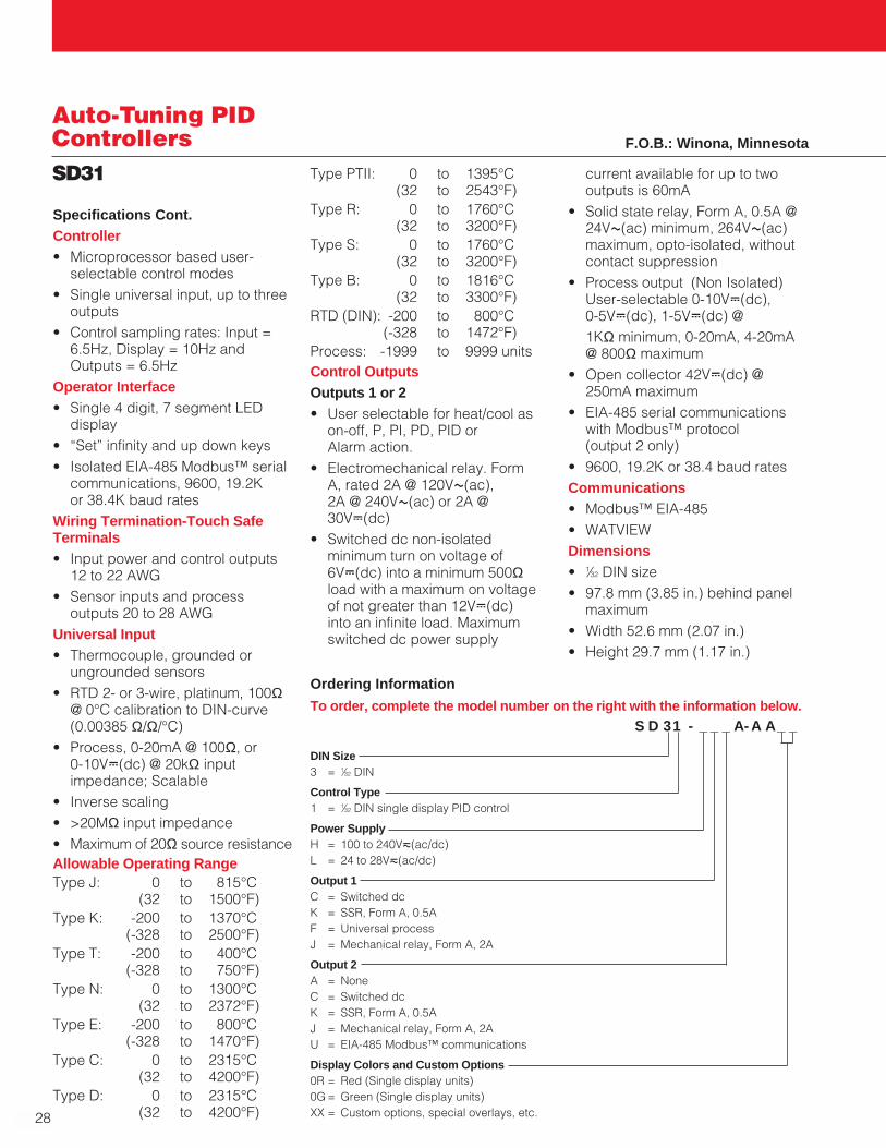
Ordering Information
To order, complete the model number on the right with the information below.S D 31 - _ _ _ A- A A_ _
DIN Size3 = 1⁄32 DIN
Control Type1 = 1⁄32 DIN single display PID control
Power SupplyH = 100 to 240Vı(ac/dc)L = 24 to 28Vı(ac/dc)
Output 1C = Switched dcK = SSR, Form A, 0.5AF = Universal processJ = Mechanical relay, Form A, 2A
Output 2A = NoneC = Switched dcK = SSR, Form A, 0.5AJ = Mechanical relay, Form A, 2AU = EIA-485 Modbus™ communications
Display Colors and Custom Options0R = Red (Single display units)0G = Green (Single display units)XX = Custom options, special overlays, etc.
F.O.B.: Winona, Minnesota

W A T L O W
29
Sin
gle-L
oo
pA
uto
-Tu
nin
g P
ID
SD_C
Auto-Tuning PIDControllers
WATVIEW HMI (Human Machine Interface)
• Permits operation, configurationand data logging via a standardWindows® PC
Infrared communications (optional)
• Facilitates recipe managementand data logging
• Allows easier controller setup,operation and monitoring
Dual displays
• Provides better recognition ofprocess changes
Specifications
Line Voltage/Power
• 100 to 240VÅ(ac), +10/-15percent; (85-264VÅ[ac]) 50/60Hz, ±5 percent
• 24Vı(ac/dc), +10/-15 percent;50/60Hz, ±5 percent
• 10VA maximum power consumption
• Data retention upon power failurevia nonvolatile memory
Environment
• -18 to 65°C (0 to 149°F) operatingtemperature
• -40 to 85°C (-40 to 185°F) storagetemperature
• 0 to 90 percent RH, non-condensing
The features and performanceoffered by SERIES SD_C controllersmake them ideally suited for a broadrange of applications in temperatureand process control.
The SERIES SD_C controllersinclude a universal sensor input withup to three outputs that can beprogrammed for heat or cool temp-erature control or to operate asprocess or deviation alarms.Programming inverse scaling is alsosimplified with the user-friendly set-up menu, providing additional valuewithout additional cost.
Advanced features of SERIES SD_Ccontrollers include EIA-485 Modbus™serial communications, Watlow’sINFOSENSE™ sensor technology,infrared remote communicationsoperation, Watlow’s patented UserDefinable Menu System and a “Saveand Restore” feature that allows therestoration of either factory or user-defined settings.
Available in 1⁄32, 1⁄16, 1⁄8 and 1⁄4 DIN-panel mount sizes, Watlow’s SERIESSD_C controllers are backed by anindustry leading three-year warrantyfrom Watlow Winona. The SERIESSD_C controllers are NSF, UL® and C-UL® listed, CSA and CE certifiedand include the NEMA 4X (IP65) seal.
Features and Benefits
INFOSENSE™ sensor technology
• Improves sensor accuracy by aminimum of 50 percent
User Defined Menu System
• Allows the user to assign up to 20 parameters in the operationsmenu
• Improves operational efficiency
“Save and Restore” feature
• Allows the user to save individualor factory settings
Variable burst fire
• Prolongs heater life
• Reduces replacement costsWindows® is a registered trademark of MicrosoftCorporation.
InfraredConfigure**
InfraredMonitor**
*1/32 DIN cannot have an Output 3.**Infrared option is not available on 1/32 DIN.
SDSD2 31
SDSD%
ControlInput
Output 1
Control or AlarmOutput 2
Control, Alarm or CommunicationsOutput 3
Control or Alarm
*

1⁄32 DIN 97.8 mm 52.6 mm 29.7 mm(3.85 in.) (2.07 in.) (1.17 in.)
1⁄16 DIN 97.8 mm 52.1 mm 52.1 mm(3.85 in.) (2.05 in.) (2.05 in.)
1⁄8 DIN 97.8 mm 52.8 mm 99.8 mmVertical (3.85 in.) (2.08 in.) (3.93 in.)
1⁄8 DIN 97.8 mm 99.8 mm 52.8 mmHorizontal (3.85 in.) (3.93 in.) (2.08 in.)
1⁄4 DIN 101.1 mm 99.8 mm 99.8 mm(3.98 in.) (3.93 in.) (3.93 in.)
30
Auto-Tuning PIDControllersSD_C
Dimensions
DIN Size Behind Panel Width Height(max.)
Accuracy
• Calibration accuracy and sensor conformity: ±0.1 percent of span, ±1°C @ the calibrated ambient temperature and rated line voltage
• Calibration ambient temperature = 25°C ±3°C (77°F ±5°F)
• Accuracy span: 540°C (1000°F)minimum
• Temperature stability: ±0.1°C/°C(±0.2°F/°F) rise in ambientmaximum
Agency Approvals
• UL® 3121, C-UL®‚ CSA, CE,NEMA 4X/IP65
• Limit version features FM approval
• NSF for Type J, K, T and Ethermocouples
Controller
• Microprocessor based user-selectable control modes
• Single universal input, up to threeoutputs
• Control sampling rates: Input = 6.5Hz, Display = 10Hz,and Outputs = 6.5Hz
Operator Interface
• Dual 4 digit, 7 segment LEDdisplays
• Advance, infinity and up downkeys
• Optional IrDA infrared port (notavailable on 1⁄32 DIN)
• Isolated EIA-485 Modbus™ serialcommunications. 9600, 19.2K or38.4K baud rates
Wiring Termination -Touch SafeTerminals
• Input power and control outputs12 to 22 AWG
• Sensor inputs and processoutputs 20 to 28 AWG
Universal Input
• Thermocouple, grounded orungrounded sensors
• RTD 2- or 3-wire, platinum, 100Ω@ 0°C calibration to DIN-curve (0.00385 Ω/Ω/°C)
• Process, 0-20mA @ 100Ω, or 0-10VÎ(dc) @ 20kΩ inputimpedance; Scalable
• Inverse scaling
• >20MΩ input impedance
• Maximum of 20Ω sourceresistance
Allowable Operating RangeType J: 0 to 815°C
(32 to 1500°F)Type K: -200 to 1370°C
(-328 to 2500°F)Type T: -200 to 400°C
(-328 to 750°F)Type N: 0 to 1300°C
(32 to 2372°F)Type E: -200 to 800°C
(-328 to 1470°F)Type C: 0 to 2315°C
(32 to 4200°F)Type D: 0 to 2315°C
(32 to 4200°F)Type PTII: 0 to 1395°C
(32 to 2543°F)Type R: 0 to 1760°C
(32 to 3200°F)Type S: 0 to 1760°C
(32 to 3200°F)Type B: 0 to 1816°C
(32 to 3300°F)RTD (DIN): -200 to 800°C
(-328 to 1472°F)Process: -1999 to 9999 unitsControl OutputsOutputs 1, 2 , 3 (Output 3 notavailable on 1⁄32 DIN)
• User selectable for heat/cool ason-off, P, PI, PD, PID or Alarmaction. Not valid for limit controls
• Electromechanical relay. Form A,rated 2A @ 120VÅ(ac), 2A @240VÅ(ac) or 2A @ 30VÎ(dc)
• Switched dc non-isolatedminimum turn on voltage of6VÎ(dc) into a minimum 500Ωload with a maximum on voltageof not greater than 12VÎ(dc) intoan infinite load. Maximum switcheddc power supply current availablefor up to two outputs is 60mA
• Solid state relay, Form A, 0.5A @24VÅ(ac) minimum, 264VÅ(ac)maximum, opto-isolated, withoutcontact suppression
Specifications Cont.
W A T L O W
31
Sin
gle-L
oo
pA
uto
-Tu
nin
g P
ID
SD_C
Auto-Tuning PIDControllers
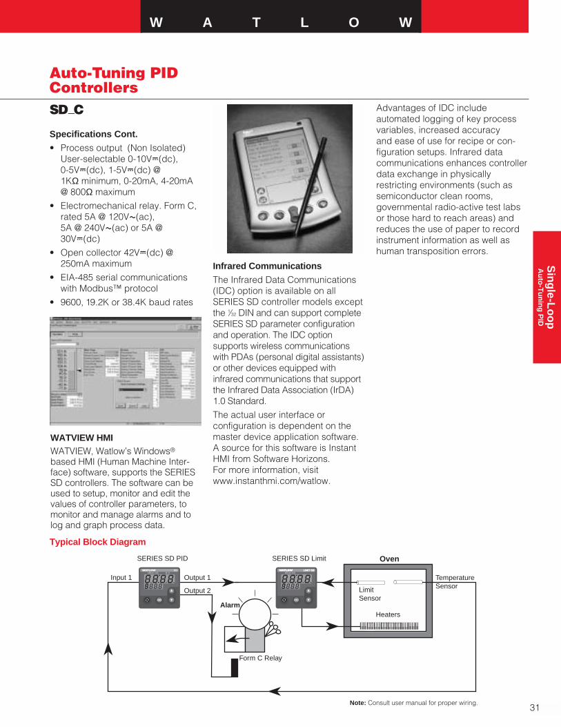
WATVIEW HMIWATVIEW, Watlow’s Windows®
based HMI (Human Machine Inter-face) software, supports the SERIESSD controllers. The software can beused to setup, monitor and edit thevalues of controller parameters, tomonitor and manage alarms and tolog and graph process data.
Oven
LimitSensor
TemperatureSensor
Output 1Input 1
Output 2
HeatersAlarm
Form C Relay
2 3 %2 31 %1 2 3 %
RESET
2 31
SERIES SD PID SERIES SD Limit
SD LIMIT SDLIMIT SD
Infrared Communications
The Infrared Data Communications(IDC) option is available on allSERIES SD controller models exceptthe 1⁄32 DIN and can support completeSERIES SD parameter configurationand operation. The IDC optionsupports wireless communicationswith PDAs (personal digital assistants)or other devices equipped withinfrared communications that supportthe Infrared Data Association (IrDA)1.0 Standard.
The actual user interface orconfiguration is dependent on themaster device application software.A source for this software is InstantHMI from Software Horizons. For more information, visitwww.instanthmi.com/watlow.
Advantages of IDC includeautomated logging of key processvariables, increased accuracyand ease of use for recipe or con-figuration setups. Infrared datacommunications enhances controllerdata exchange in physicallyrestricting environments (such assemiconductor clean rooms,governmental radio-active test labsor those hard to reach areas) andreduces the use of paper to recordinstrument information as well ashuman transposition errors.
Note: Consult user manual for proper wiring.
Typical Block Diagram
Specifications Cont.
• Process output (Non Isolated)User-selectable 0-10VÎ(dc), 0-5VÎ(dc), 1-5VÎ(dc) @1KΩ minimum, 0-20mA, 4-20mA @ 800Ω maximum
• Electromechanical relay. Form C,rated 5A @ 120VÅ(ac), 5A @ 240VÅ(ac) or 5A @30VÎ(dc)
• Open collector 42VÎ(dc) @250mA maximum
• EIA-485 serial communicationswith Modbus™ protocol
• 9600, 19.2K or 38.4K baud rates
32
Auto-Tuning PIDControllersSD_C Ordering Information
To order, complete the model number on the right with the information below.
SERIES SD_C = Single channel PID controllers S D _C - _ _ _ _ - _ A _ _
DIN Sizes3 = 1⁄32 DIN6 = 1⁄16 DIN8 = 1⁄8 DIN Vertical9 = 1⁄8 DIN Horizontal4 = 1⁄4 DIN
Control TypeC = PID Control Dual DisplayPower SupplyH = 100 to 240Vı(ac/dc)L = 24 to 28Vı(ac/dc)
Output 1C = Switched dcK = SSR, Form A, 0.5AF = Universal processJ = Mechanical relay, Form A, 2A
Output 2A = NoneC = Switched dcK = SSR, Form A, 0.5AJ = Mechanical relay, Form A, 2AU = EIA-485 Modbus™ communications
Output 3 (Not available on 1⁄32 DIN)A = NoneC = Switched dc/open collectorK = SSR, Form A, 0.5AF = Universal processE = Mechanical relay, Form C, 5A
Infrared Comms Options (IrDA)A = None (Default selection on 1⁄32 DIN)R = IrDA ready (Not available on 1⁄32 DIN)
Display Colors and Custom OptionsRG= Red Green (Dual display units)RR = Red Red (Not available on 1⁄32 DIN Dual Display)XX = Custom options, special overlays, etc.
F.O.B.: Winona, Minnesota
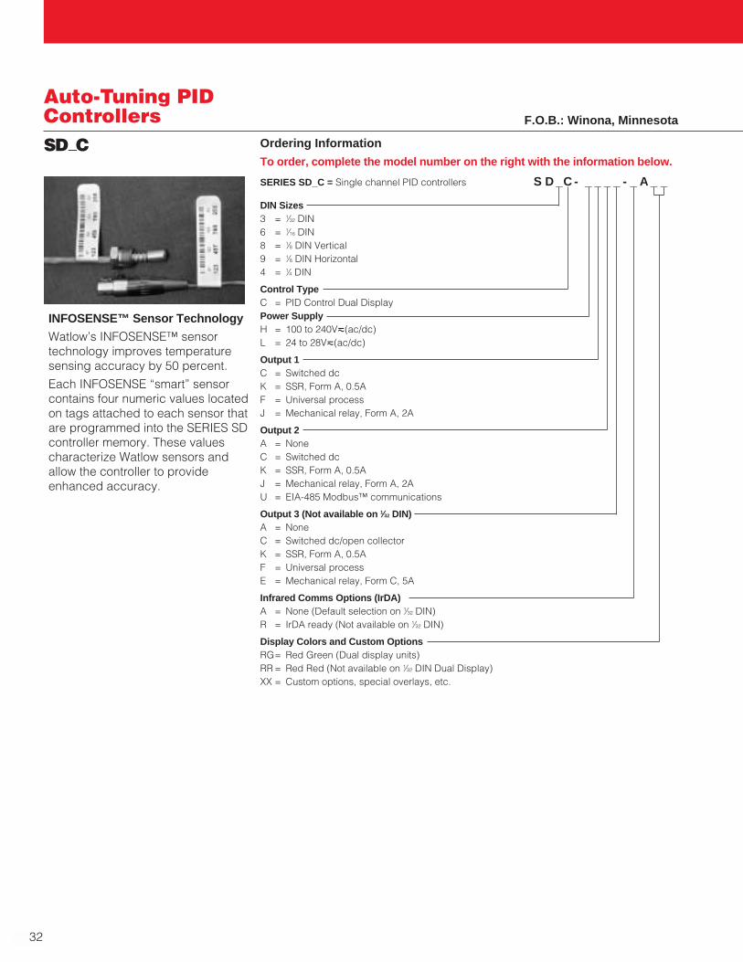
INFOSENSE™ Sensor Technology
Watlow’s INFOSENSE™ sensortechnology improves temperaturesensing accuracy by 50 percent.
Each INFOSENSE “smart” sensorcontains four numeric values locatedon tags attached to each sensor thatare programmed into the SERIES SDcontroller memory. These valuescharacterize Watlow sensors andallow the controller to provideenhanced accuracy.
W A T L O W
33
Sin
gle-L
oo
pA
uto
-Tu
nin
g P
ID
SD6C_D
Auto-Tuning PIDControllers
Specifications
Line Voltage/Power
• 100 to 240VÅ(ac), +10/-15percent; (85-264VÅ[ac]) 50/60Hz,±5 percent
• 24Vı(ac/dc), +10/-15 percent;50/60Hz, ±5 percent
• 10VA maximum powerconsumption
• Data retention upon power failurevia nonvolatile memory
Environment
• -18 to 65°C (0 to 149°F) operatingtemperature
• -40 to 85°C (-40 to 185°F) storagetemperature
• 0 to 90 percent RH, non-condensing
Accuracy
• Calibration accuracy and sensorconformity: ±0.1 percent of span,±1°C @ the calibrated ambienttemperature and rated linevoltage
• Calibration ambient temperature =25°C ±3°C (77°F ±5°F)
• Accuracy span: 540°C (1000°F)minimum
• Temperature stability: ±0.1°C/°C(±0.2°F/°F) rise in ambientmaximum
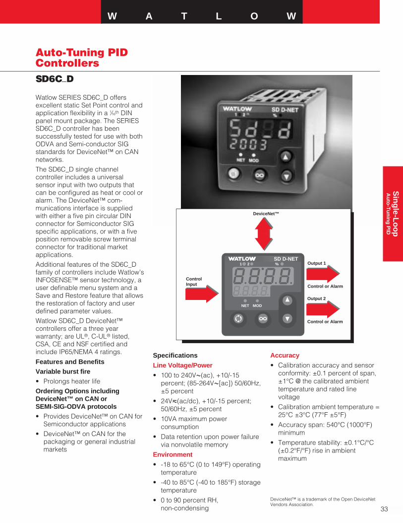
Watlow SERIES SD6C_D offersexcellent static Set Point control andapplication flexibility in a 1⁄16th DINpanel mount package. The SERIESSD6C_D controller has beensuccessfully tested for use with bothODVA and Semi-conductor SIGstandards for DeviceNet™ on CANnetworks.The SD6C_D single channelcontroller includes a universalsensor input with two outputs thatcan be configured as heat or cool oralarm. The DeviceNet™ com-munications interface is suppliedwith either a five pin circular DINconnector for Semiconductor SIGspecific applications, or with a fiveposition removable screw terminalconnector for traditional marketapplications.Additional features of the SD6C_Dfamily of controllers include Watlow’sINFOSENSE™ sensor technology, auser definable menu system and aSave and Restore feature that allowsthe restoration of factory and userdefined parameter values. Watlow SD6C_D DeviceNet™controllers offer a three yearwarranty; are UL®, C-UL® listed,CSA, CE and NSF certified andinclude IP65/NEMA 4 ratings.
Features and BenefitsVariable burst fire• Prolongs heater lifeOrdering Options includingDeviceNet™ on CAN or SEMI-SIG-ODVA protocols• Provides DeviceNet™ on CAN for
Semiconductor applications• DeviceNet™ on CAN for the
packaging or general industrialmarkets
DeviceNet™ is a trademark of the Open DeviceNetVendors Association.
SDSD2 31
SDSD%21 %SD D-NET
NET MOD
ControlInput
Output 1
Control or Alarm
Output 2
Control or Alarm
DeviceNet™
34
Auto-Tuning-PIDControllersSD6C_D
Agency Approvals
• UL® 3121, C-UL®‚ CSA, CE,IP65/NEMA 4X and NSF-2
• Microprocessor based user-selectable control modes
• Single universal input, up to threeoutputs
• Control sampling rates: Input =6.5Hz, Display = 10Hz andOutputs = 6.5Hz
Operator Interface
• Dual 4 digit, 7 segment LEDdisplays
• Advance, infinity and up downkeys
• DeviceNet™ on CAN or SEMI-SIG-ODVA protocols
Allowable Operating Range
Type J: 0 to 815°C(32 to 1500°F)
Type K: -200 to 1370°C(-328 to 2500°F)
Type T: -200 to 400°C(-328 to 750°F)
Type N: 0 to 1300°C(32 to 2372°F)
Type E: -200 to 800°C(-328 to 1470°F)
Type C: 0 to 2315°C(32 to 4200°F)
Type D: 0 to 2315°C(32 to 4200°F)
Type PTII: 0 to 1395°C(32 to 2543°F)
Type R: 0 to 1760°C(32 to 3200°F)
Type S: 0 to 1760°C(32 to 3200°F)
Type B: 0 to 1816°C(32 to 3300°F)
RTD (DIN): -200 to 800°C(-328 to 1472°F)
Process: -1999 to 9999 units
Specifications Cont.
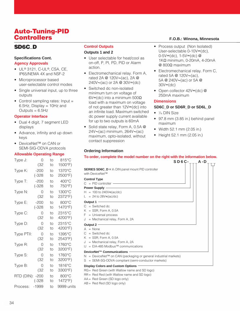
Ordering Information
To order, complete the model number on the right with the information below.S D 6 C- _ _ _ A -D _ _ _
SERIES SD6C_D = 1⁄16 DIN panel mount PID controller with DeviceNet™
Control TypeC = PID controllerPower SupplyH = 100 to 240Vı(ac/dc)L = 24 to 28Vı(ac/dc)
Output 1C = Switched dcK = SSR, Form A, 0.5AF = Universal processJ = Mechanical relay, Form A, 2A
Output 2A = NoneC = Switched dcK = SSR, Form A, 0.5AJ = Mechanical relay, Form A, 2AU = EIA-485 Modbus™ communications
DeviceNet™ CommunicationsN = DeviceNet™ on CAN (packaging or general industrial markets)S = SEMI-SG-ODVA compliant (semi-conductor markets)
Display Colors and Custom OptionsRG= Red Green (with Watlow name and SD logo)RR = Red Red (with Watlow name and SD logo)AA = Red Green (SD logo only)AB = Red Red (SD logo only)
Control OutputsOutputs 1 and 2• User selectable for heat/cool as
on-off, P, PI, PD, PID or Alarmaction.
• Electromechanical relay. Form A,rated 2A @ 120VÅ(ac), 2A @240VÅ(ac) or 2A @ 30VÎ(dc)
• Switched dc non-isolatedminimum turn on voltage of6VÎ(dc) into a minimum 500Ωload with a maximum on voltageof not greater than 12VÎ(dc) intoan infinite load. Maximum switcheddc power supply current availablefor up to two outputs is 60mA
• Solid state relay, Form A, 0.5A @24VÅ(ac) minimum, 264VÅ(ac)maximum, opto-isolated, withoutcontact suppression
• Process output (Non Isolated)User-selectable 0-10VÎ(dc), 0-5VÎ(dc), 1-5VÎ(dc) @1KΩ minimum, 0-20mA, 4-20mA @ 800Ω maximum
• Electromechanical relay. Form C,rated 5A @ 120VÅ(ac), 5A @ 240VÅ(ac) or 5A @30VÎ(dc)
• Open collector 42VÎ(dc) @250mA maximum
DimensionsSD6C_D or SD6R_D or SD6L_D• 1⁄16 DIN Size• 97.8 mm (3.85 in.) behind panel
maximum• Width 52.1 mm (2.05 in.)• Height 52.1 mm (2.05 in.)
F.O.B.: Winona, Minnesota

W A T L O W
35
Sin
gle-L
oo
pA
uto
-Tu
nin
g P
ID
SERIES 96
Auto-Tuning PIDControllers
Watlow’s SERIES 96 is a powerful 1⁄16 DIN dual display controller thatoffers many advanced functions.This controller can be tailored toperform hardware and softwareneeds with hardware modules thatare plugable and exchangeable,and software menus that may beuser programmed to fit exactapplication requirements.With one universal input, a secondauxiliary input and four outputs theSERIES 96 can be programmed toperform: temperature measurement,input event switching, remote setpoint input, heating, boost heating,cooling, alarms, digital communica-tions and retransmit.With fast 10Hz sampling, variabletime base burst firing outputs, NEMA4X front panel and 0.1 percentcalibration accuracy, this controllercan easily handle some of thetoughest application needs.
Features and Benefits
Burst fire
• Increases heater life / bettertemperature controllability
One input, one auxiliary input, fouroutputs
• Powerful flexibility at a competitiveprice
No dipswitches
• Easily configurable from the frontpanel
Multiple set points
• Flexible automatic control
Plugable output modules
• Field expandable
Fast 10Hz sampling
• Improved control responsiveness
Programmable menus (Patented)
• Can be self-tailored for exact userneeds
Open loop break protection
• Indication of thermal loop problem
NEMA 4X (IP65)1
• Water and corrosion resistant frontpanel can be washed down
16 programmable ramp and soaksteps
• Profiles of dynamic productionprocesses can be programmedinto the controller
Automatic-tuning
• Easy one step tuning of PIDcontrol parameters
Applications• Packaging
• Semiconductor
• Food processing
• Lab equipment
• Furnace and ovens
• Plastics
a To effect NEMA 4X (IP65) rating requires aminimum mounting panel thickness of 1.5 mm(0.06 in.) and surface finish not rougher than0.000812 mm (0.000032 in.).
b Electromechanical relays warranted for 100,000closures only. Solid state switching devicesrecommended for applications requiring fastcycle times or extended service life.
2 3 4 %96
1Input 1Process
Input 2Event
Output 1Control
Output 2Control or Alarm
Output 3Alarm
Output 4Alarm, Analog or Communications
Specifications
Operating Environment• 0 to 65°C (32 to 149°F)
Controller• Microprocessor-based, user
selectable control modes
• Heat and cool auto-tune for control outputs
• Universal input one, auxiliaryinput two, four outputs
• Control outputs user selectable ason-off, P, PI, PID
Warranty2
• Industry leading three-years
36
Auto-Tuning PIDControllersSERIES 96
• Input sampling rates: Single input10Hz (100ms), dual input 5Hz(200ms) digital filter adjustable
• Display update: 2Hz (500ms),time filter adjustable
• Output update: burst, 0.1 to 999.9seconds
• Input/Output/Communicationisolation
• Displayed in °C, °F, or processunits
Operator Interface• Dual four-digit LED displays:
upper 10.2 mm (0.4 in.), lower 6.2 mm (0.244 in.)
• Advance, Up Arrow, Down Arrow,Infinity tactile keys
Standard Conditions ForSpecifications• Ambient temperature 25°C (77°F)
±3°C, rated line voltage, 50 to 60Hz, 0 to 90 percentRH non-condensing, 15 minutewarm-up
Universal Input 1Thermocouple• Type J, K, T, N, C (W5), E, Pt 2, D
(W3), B, R, S thermocouple
• >20MΩ input impedance
• Maximum 20Ω source resistance
• 30µA open detection bias
RTD• 2- or 3-wire platinum, 100Ω• JIS and DIN-curves
• Whole or tenth degree indication
• 150µA nominal RTD excitationcurrent
Process• Range selectable: 0-10VÎ(dc),
0-5VÎ(dc), 1-5VÎ(dc), 0-20mA,4-20mA
• Voltage input impedance 20kΩ• Current input impedance 100Ω• Minimum current source
resistance 1MΩ
• Input resolution 50,000 bits(approx.) at full scale
• mV input impedance 20MΩInput 2Event Input• Contact or voltage
• 20KΩ input impedance
• Voltage input: event high state 3 to 36VÎ(dc), event low state 0 to 2VÎ(dc)
• Resistance/contact input: eventhigh state >23kΩ, event low state0 to 2kΩ
Remote Set Point Input: mA orVÎ(dc) Range Selectable• Voltage input impedance 20kΩ• Current input impedance 100ΩOutput TypesOpen Collector/Switched DC• Open collector configuration:
Maximum voltage 42VÎ(dc)Maximum current 200mA Maximum on resistance 1.1ΩMaximum off state leakagecurrent 100µA
• Switched dc configuration:Switched dc supply voltage 22 to 28VÎ(dc) dc supply current limited to 30mA
Solid State Relay• Optically isolated
• Zero cross switched
• Without contact suppression
• Minimum load current 0.5mA rms
• Maximum current 0.5A rms at 20 to 280VÅ(ac)
• Maximum off state leakagecurrent 10µA rms
• For resistive loads only, must useRC suppression for inductiveloads
Electromechanical Relay• Form C contact configuration
• Minimum load current 10mA @5VÎ(dc)
• Rated resistive and inductiveloads: 2A @ 250VÅ(ac) or30VÎ(dc) maximum
• Electrical life 100,000 cycles atrated current
• For resistive loads only, must useRC suppression for inductiveloads
Process
• Range selectable: 0-20mA, 4-20mA, 0-5VÎ(dc), 1-5VÎ(dc),0-10VÎ(dc)
• Reverse or direct acting
• 0 to 10VÎ(dc) voltage output into1000Ω minimum load resistance
• 0 to 20mA current output into800Ω maximum load resistance
• Resolution:
VÎ(dc) ranges = 2.5mV nominalmA ranges = 5µA nominal
• Calibration accuracy:
VÎ(dc) ranges = ±15mVmA ranges = ±30µA
• Temperature stability 100ppm/°CRetransmit
• Range selectable: 0-20mA, 4-20mA, 0-5VÎ(dc), 1-5VÎ(dc),0-10VÎ(dc)
• 0 to 10VÎ(dc) voltage output intoa 1,000Ω minimum loadresistance
• 0 to 20mA current output into an800Ω maximum load resistance
• Resolution:
VÎ(dc) ranges = 2.5mV nominalmA ranges = 5µA nominal
• Calibration accuracy:
VÎ(dc) ranges = ±15mVmA ranges = ±30µA
• Temperature stability 100ppm/°CCommunications
• EIA/TIA-485, EIA/TIA-232
• Opto-isolated • Modbus™ RTU protocol• 1200, 2400, 4800, 9600, 19200
baud rates• 32 maximum units can be
connected (With additional 485repeater hardware, up to 247units may be connected)
Specifications Cont.

W A T L O W
37
Sin
gle-L
oo
pA
uto
-Tu
nin
g P
ID
SERIES 96
Auto-Tuning PIDControllers
Accuracy• Input rangesType J 0 to 750°C
(32 to 1382°F)Type K -200 to 1250°C
(-328 to 2282°F)Type T -200 to 350°C
(-328 to 662°F)Type N 0 to 1250°C
(32 to 2282°F)Type E -200 to 900°C
(-328 to 1470°F)Type C(W5) 0 to 2315°C
(32 to 4200°F)Type D(W3) 0 to 2315°C
(32 to 4200°F)Pt 2 0 to 1393°C
(32 to 2540°F)Type R 0 to 1450°C
(32 to 2642°F)Type S 0 to 1450°C
(32 to 2642°F)Type B 870 to 1700°C
(1598 to 3092°F)DIN -200 to 800°C
(-328 to 1472°F)JIS -200 to 630°C
(-328 to 1166°F)Process -1999 to 9999 unitsThermocouple Inputs• Calibration accuracy ±0.1 percent
of span ±1°C at standard conditionsExceptions: Type T: 0.12 percent of span for -200°C to -50°C (-328°F to -58°F)Types R and S: 0.15 percent ofspan for 0°C to 100°C (32°F to212°F)Type B: 0.24 percent of span for 870°C to 1700°C (1598°F to3092°F)
• Accuracy span: 540°C (1000°F)minimum
• Temperature stability: ±0.1degree per degree change inambient
RTD Inputs• Calibration accuracy ±0.1 percent
of span ±1°C at standardconditions
• Accuracy span: 540°C (1000°F)minimum
• Temperature stability: ±0.05degree per degree change inambient
Process Inputs• Voltage input ranges
Accuracy ±15mV ±1 LSD atstandard conditionsTemperature stability±100ppm/°C maximum
• Milli-amp input rangesAccuracy ±30µA ±1 LSD atstandard conditionsTemperature stability±100ppm/°C maximum
Agency Approvals• UL® 916, File #E185611, C-UL®,
CE, NEMA 4XTerminals• Touch safe• 22 to 12 AWG Power • 100-240VÅ(ac) +10 percent,
-15 percent; 50/60Hz, ±5 percent• 24-28VÅ(ac) or VÎ(dc) +10
percent, -15 percent; 50/60Hz, ±5 percent
• 7.0VA maximum powerconsumption
• Data retention upon power failurevia nonvolatile memory
Operating Environment• 0 to 65°C (32 to 149°F)• 0 to 90 percent RH, non-condensing• Storage temperature: -40 to 85°C
(-40 to 185°F)Controller Weight (approx.)• 0.2 kg (0.4 lb)
Allowable Operating Ranges
Type J 1.0 0 to 815°C(32 to 1500°F)
0.1 0 to 815°C(32 to 1500°F)
Type K 1.0 -270 to 1370°C(-454 to 2500°F)
0.1 -200 to 1000°C(-328 to 1832°F)
Type T 1.0 -270 to 400°C(-454 to 750°F)
0.1 -200 to 400°C(-328 to 750°F)
Type N 1.0 0 to 1300°C(32 to 2372°F)
0.1 0 to 1000°C(32 to 1832°F)
Type E 1.0 -270 to 800°C(-454 to 1470°F)
0.1 -200 to 800°C(-328 to 1472°F)
Type C 1.0 0 to 2315°C(32 to 4200°F)
0.1 0 to 1000°C(32 to 1832°F)
Type D 1.0 0 to 2315°C(32 to 4200°F)
0.1 0 to 1000°C(32 to 1832°F)
Pt 2 1.0 0 to 1395°C(32 to 2543°F)
0.1 0 to 1000°C(32 to 1832°F)
Type R 1.0 0 to 1760°C(32 to 3200°F)
Type S 1.0 0 to 1760°C(32 to 3200°F)
Type B 1.0 0 to 1816°C(32 to 3300°F)
DIN 1.0 -200 to 800°C(-328 to 1472°F)
0.1 -200 to 800°C(-328 to 1472°F)
JIS 1.0 -200 to 630°C(-328 to 1166°F)
0.1 -200 to 630°C(-328 to 1166°F)
Process -1999 to 9999 units
Specifications Cont.

Input 1
Input 2
Output 1
Output 2
Output 3
Output 4
38
Auto-Tuning PIDControllersSERIES 96
Dimensions
OverallHeight: 52 mm (2.05 in.)
Width: 52 mm (2.05 in.)
Length: 107 mm (4.2 in.)
Depth behind panel surface98.4 mm (3.875 in.)
Ordering Information
To order, complete the code number on the right with the information below:9 6 _ _ - _ _ _ _ - _ _ _ _
SERIES 96 = Microprocessor-based 1⁄16 DIN, with universalinput 1. Options include: software, power supply, input 2, outputs and display color.
Power SupplyA = 100-240Vı(ac/dc)B = 24-28Vı(ac/dc)
Input 20 = None1 = Event input and 0-5VÎ(dc)/4-20mA (Remote set point input)
Output 1C = Switched dc/open collectorD = Electromechanical relay, Form C, 2A, without RC suppressionF = Universal Process, range selectable: 0-20mA, 4-20mA,
0-5VÎ(dc), 1-5VÎ(dc), 0-10VÎ(dc)K = 0.5A solid state relay without RC suppression
Output 2A = NoneC = Switched dc/open collectorD = Electromechanical relay, Form C, 2A, without RC suppressionF = Universal Process, range selectable: 0-20mA, 4-20mA,
0-5VÎ(dc), 1-5VÎ(dc), 0-10VÎ(dc)K = 0.5A solid state relay without RC suppression
Output 3A = NoneD = Electromechanical relay, Form C, 2A, without RC suppression
Output 4A = NoneD = Electromechanical relay, Form C, 2A, without RC suppressionR = 232 CommunicationsU = 485 CommunicationsM = Universal Retransmit, range selectable: 0-20mA, 4-20mA,
0-5VÎ(dc), 1-5VÎ(dc), 0-10VÎ(dc)
Software/Preset Parameters00 = Standard software
Display/OverlayUpper/Lower Upper/Lower
RR = Red/Red display GR = Green/Red displayRG = Red/Green display GG = Green/Green display
2 3 4 %96
1
52.070 mm(2.050 in.)
52.070 mm(2.050 in.)
Panel Cutout44.958 mm x 44.958 mm
(1.77 in. x 1.77 in.)
107.747 mm(4.242 in.)
9.322 mm(0.367 in.)
98.425 mm(3.875 in.)
59.182 mm(2.330 in.)
Functionality Matrix
Univ
ersa
lIn
put
Even
t &Re
mot
eSe
t Poi
nt
Cont
rol
Alar
m
Retra
nsm
it
232
485
Com
m
F.O.B.: Winona, Minnesota

W A T L O W
39
Sin
gle-L
oo
pA
uto
-Tu
nin
g P
ID
SERIES 988/989
Auto-Tuning PIDControllers
Watlow's SERIES 988 (vertical) and SERIES 989 (horizontal)temperature/process controllers aredesigned and manufactured for thedemanding requirements of theindustrial controller market. No othercontroller offers the flexibility,compact size and durability of theSERIES 988/989. The controller’sindustry leading feature set is itscompact 1⁄8 DIN size and NEMA 4X1(IP65) water and corrosion resistantfront panel.
The SERIES 988/989 has the auto-tuning and alarm features you wouldexpect. Additionally, several uniquecontrol algorithms, not common tothis price range, extend the SERIES988/989’s application potential. Fromthe long list of product features, theSERIES 988/989's ability to providesingle unit cascade control of aprocess is perhaps the most unique.Other features include heater currentmonitoring, remote set point input,differential or ratio control.
Performance Capabilities• Accuracy to 0.1 percent of span
• Operating environment 0 to 65°C (32 to 149°F)
Features and Benefits
Three inputs and four outputs
• Provide application versatility
Universal high or low voltagepower supply, horizontal or verticalmounting and display color options
• Add to application versatility
A 10Hz sampling rate, along withthe burst fire
• Provides precise process control
Enhanced software option
• Provides advanced cascade, ratioor dual PID control
Signal conditioner power supplyoptions
• Eliminate the need for externaldevices
Serial communications
• Support for one-on-one as well asremote networking of controllers
UL®, CE and NEMA 4X (IP65)approvals
• Help ensure product and operatorsafety
Dual digital displays
• Provide simultaneous viewing ofthe set point and the actual process
Three-year warranty2
• Provides Control Confidence®
Applications
• Any process requiring cascade,ratio, burst fire or slidewirefeedback control
• Food processing
• Packaging
• Plastics processing
• Semiconductor manufacturing
1 To effect NEMA 4X (IP65) rating requires aminimum mounting panel thickness of 1.5 mm(0.06 in.) and surface finish not rougher than0.000812 mm (0.000032 in.).
TL WWA
PROCESS
L1 L2 L3 L4
DEV
% OUTDISPLAY
SERIES 988
MODE
AUTOMAN
Input 1Type B, C, D, E, J, K, N, R, S, T or Pt 2Thermocouple, DIN/JIS RTD orProcess
Input 3Digital Event
Input 2Type B, C, D, E, J, K, N, R, S, T or Pt 2Thermocouple, DIN/JIS RTD orProcess, Slidewire,Current Transformer or Digital Event
Output 1Closed Loop PID, on-off ControlOpen Loop Percent Power
Output 2Closed Loop PID, on-off ControlOpen Loop Percent Power Control AlarmTransmitter Power Supply
Output 3AlarmTransmitter Power SupplyAnalog Retransmit
Output 4AlarmTransmitter Power SupplySerial Communications
Auto-tuneHeat/Cool
Process Deviation from Set Point
Percent Power
2 Electromechanical relays warranted for 100,000closures only. Solid state switching devicesrecommended for applications requiring fastcycle times or extended service life.
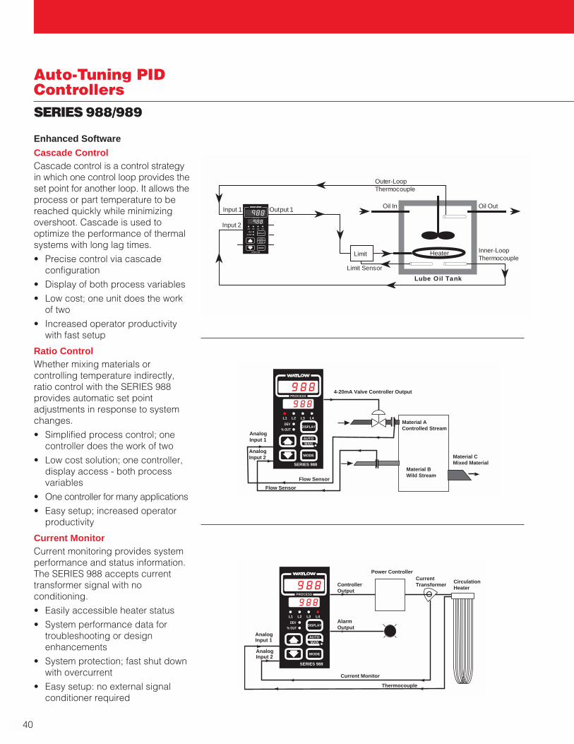
40
Auto-Tuning PIDControllersSERIES 988/989
TLTL WWA
PROCESS
L1 L2 L3 L4
DEV
% OUTDISPLAY
MODE
AUTOMAN
SERIES 988
AnalogInput 1
AnalogInput 2
4-20mA Valve Controller Output
Material AControlled Stream
Material BWild Stream
Material CMixed Material
Flow Sensor
Flow Sensor
TLTL WWA
PROCESS
L1 L2 L3 L4
DEV
% OUTDISPLAY
MODE
AUTOMAN
SERIES 988
Current Transformer
AnalogInput 2
AnalogInput 1
ControllerOutput
Circulation Heater
Power Controller
Thermocouple
AlarmOutput
Current Monitor
TLTL WWA
PROCESS
L1 L2 L3 L4
DEV
% OUTDISPLAY
MODE
AUTOMAN
SERIES 988
Input 1
Input 2
Output 1
Limit
Limit Sensor
Oil In
Heater
Oil Out
Inner-LoopThermocouple
Lube Oil Tank
Outer-Loop Thermocouple
Enhanced Software
Cascade ControlCascade control is a control strategyin which one control loop provides theset point for another loop. It allows theprocess or part temperature to bereached quickly while minimizingovershoot. Cascade is used tooptimize the performance of thermalsystems with long lag times.
• Precise control via cascadeconfiguration
• Display of both process variables
• Low cost; one unit does the workof two
• Increased operator productivitywith fast setup
Ratio ControlWhether mixing materials orcontrolling temperature indirectly,ratio control with the SERIES 988provides automatic set pointadjustments in response to systemchanges.
• Simplified process control; onecontroller does the work of two
• Low cost solution; one controller,display access - both processvariables
• One controller for many applications
• Easy setup; increased operatorproductivity
Current MonitorCurrent monitoring provides systemperformance and status information.The SERIES 988 accepts currenttransformer signal with noconditioning.
• Easily accessible heater status
• System performance data fortroubleshooting or designenhancements
• System protection; fast shut downwith overcurrent
• Easy setup: no external signalconditioner required

W A T L O W
41
Sin
gle-L
oo
pA
uto
-Tu
nin
g P
ID
SERIES 988/989
Auto-Tuning PIDControllers
TL WWA
PROCESS
L1 L2 L3 L4
DEV
% OUTDISPLAY
MODE
AUTOMAN
SERIES 988
Input 1
Input 2
Slide Wire Feedback / Position Sensor
Thermocouple
CCW - Open
CW - Close
Enhanced Software Cont.
Slidewire Feedback Valve ControlValve positioning feedback (percentopen, percent close) providesprecise process control. The SERIES988 is configurable for a wide varietyof valves.
• Accepts virtually any valve input
• Front panel valve position display
• Increased valve life with anti-hunting parameter
• Greater process efficiency withprecise control
• Easy setup; increased operatorproductivity
Product Highlights
Easy to OperateThe SERIES 988's operator interfacefeatures the simplicity you expectfrom a Watlow controller. The displaykey allows the operator to viewinformation pertinent to the process,including, among others, deviationfrom set point, percent output andunits of measurement.
The display key also returns theoperator to the process and set pointdisplay from anywhere in the menusystem. The setup menu issegmented into input, output, global,and communication parameters andyou can move forward or backwardthroughout the parameter sequence.
Use Up To Four OutputsThe controller can have up to fouroutputs total, including the standardWatlow output options, along withretransmit and communications. Upto three outputs can be defined as apower supply output to powerexternal signal conditioners,eliminating the need for an externalpower supply. The output types arerecognized by the controller tosimplify setup and operation, with noneed for DIP switches.
Three Inputs Allow GreaterFlexibilityTo accommodate unique systemconfigurations, the SERIES 988offers two universal analog inputsand one event (digital) input. Theevent input allows the operator toselect a function at the close of aswitch. This can lock out the frontpanel, switch PID values, go to aremote or second set point, etc. Theinputs are optically isolated from alloutputs, eliminating the need forexternal isolation circuitry.
Specifications
Control Mode• Dual input, quad output, optional
retransmit of set point or processvariable
• Programmable direct and reverse acting control outputs
• One step auto-tuning
Agency Approvals• CE
• 89/336/EEC ElectromagneticCompatibility Directive
• EN 50081-2: 1994 Emissions
• EN 50082-2: 1994 Immunity
• 73/23/EEC Low Voltage Directive
• EN 61010-1: 1993 Safety
• UL® #873, C-UL® File #43684
• NEMA 4X
Operator Interface• Local/remote set point capability
• Dual, 4 digit LED displays Upper: 10 mm (0.4 in.) Lower: 8 mm (0.3 in.)
• MODE, AUTO/MAN, DISPLAY, UP and DOWN keys
Accuracy• Calibration accuracy and sensor
conformity: ±0.1 percent of span, ±1 LSD, 25°C ±3°C (77°F ±5°F)ambient and rated line voltage±10 percent
• Accuracy span: 540°C (1000°F)minimum
• Temperature stability: 0.1°C/°C(±0.2°F/°F) change in ambient
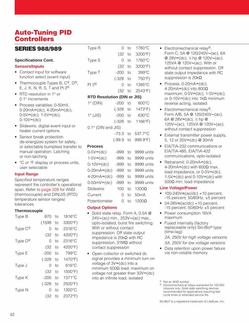
42
Auto-Tuning PIDControllersSERIES 988/989 Type R 0 to 1760°C
(32 to 3200°F)
Type S 0 to 1760°C
(32 to 3200°F)
Type T -200 to 399°C
(-328 to 750°F)
Pt 21 0 to 1395°C
(32 to 2543°F)
RTD Resolution (DIN or JIS)
1° (DIN) -200 to 800°C
(-328 to 1472°F)
1° (JIS) -200 to 630°C
(-328 to 1166°F)
0.1° (DIN and JIS)
-73.3 to 537.7°C
(-99.9 to 999.9°F)
Process0-5VÎ(dc) -999 to 9999 units
1-5VÎ(dc) -999 to 9999 units
0-10VÎ(dc) -999 to 9999 units
0-20mAÎ(dc) -999 to 9999 units
4-20mAÎ(dc) -999 to 9999 units
0-50mVÎ(dc) -999 to 9999 units
Slidewire 100 to 1200ΩCurrent 0 to 50mA
Potentiometer 0 to 1200ΩOutput Options• Solid state relay, Form A, 0.5A @
24VÅ(ac) min., 253VÅ(ac) max.,opto-isolated, burst fire switching.With or without contactsuppression. Off state outputimpedance is 20kΩ with RCsuppression, 31MΩ withoutcontact suppression
• Open collector or switched dcsignal provides a minimum turn onvoltage of 3VÎ(dc) into aminimum 500Ω load; maximum onvoltage not greater than 32VÎ(dc)into an infinite load, isolated
Specifications Cont.
Sensors/Inputs• Contact input for software
function select (event input)
• Thermocouple Types B, C1, D1,E, J, K, N, R, S, T and Pt 21
• RTD resolution in 1° or 0.1° increments
• Process variables: 0-50mV, 0-20mAÎ(dc), 4-20mAÎ(dc), 0-5VÎ(dc), 1-5VÎ(dc), 0-10VÎ(dc)
• Slidewire, digital event input orheater current options
• Sensor break protection de-energizes system for safety, or selectable bumpless transfer tomanual operation. Latching or non-latching
• °C or °F display or process units,user selectable
Input RangeSpecified temperature rangesrepresent the controller's operationalspan. Refer to page 228 for ANSI(thermocouple) and DIN/JIS (RTD)temperature sensor ranges/tolerances.
ThermocoupleType B 870 to 1816°C
(1598 to 3300°F)
Type C1 0 to 2316°C
(32 to 4200°F)
Type D1 0 to 2316°C
(32 to 4200°F)
Type E -200 to 799°C
(-328 to 1470°F)
Type J 0 to 816°C
(32 to 1500°F)
Type K -200 to 1371°C
(-328 to 2500°F)
Type N 0 to 1300°C
(32 to 2372°F)
• Electromechanical relay2, Form C, 5A @ 120/240VÅ(ac), 6A@ 28VÎ(dc), 1⁄8 hp @ 120VÅ(ac),125VA @ 120VÅ(ac). With orwithout contact suppression. Offstate output impedance with RCsuppression is 20kΩ
• Process, 0-20mAÎ(dc), 4-20mAÎ(dc) into 800Ωmaximum, 0-5VÎ(dc), 1-5VÎ(dc),or 0-10VÎ(dc) into 1kΩ minimumreverse acting, isolated
• Electromechanical relay2, Form A/B, 5A @ 120/240VÅ(ac), 6A @ 28VÎ(dc), 1⁄8 hp @120VÅ(ac), 125VA @ 120VÅ(ac),without contact suppression
• External transmitter power supply,5, 12 or 20VÎ(dc) @ 30mA
• EIA/TIA-232 communications orEIA/TIA-485, EIA/TIA-422communications, opto-isolated
• Retransmit: 0-20mAÎ(dc), 4-20mAÎ(dc) with 600Ω max.load impedance, or 0-5VÎ(dc), 1-5VÎ(dc) and 0-10VÎ(dc) with500Ω min. load impedance
Line Voltage/Power• 100-240Vı(ac/dc) +10 percent,
-15 percent; 50/60Hz, ±5 percent• 24-28Vı(ac/dc) +10 percent,
-15 percent; 50/60Hz ±5 percent• Power consumption 16VA
maximum • Fused internally (factory
replaceable only) Slo-Blo® type(time-lag):2A, 250V for high voltage versions5A, 250V for low voltage versions
• Data retention upon power failurevia non-volatile memory
1 Not an ANSI symbol.2 Electromechanical relays warranted for 100,000
closures only. Solid state switching devicesrecommended for applications requiring fastcycle times or extended service life.
Slo-Blo® is a registered trademark of Littelfuse, Inc.

W A T L O W
43
Sin
gle-L
oo
pA
uto
-Tu
nin
g P
ID
SERIES 988/989
Auto-Tuning PIDControllers
Specifications Cont.
Ordering Information
To order, complete the code number to the right with the information below:9 8 _ _ - _ _ _ _ - _ _ _ _
SERIES 988/989 = Single channel, temperature/process controller, 1 analog input, 1 digital input, 1 analog or digital input, 4 outputs.Power Supply & Mounting6 = 24 to 28Vı(ac/dc) nominal, vertical mounting7 = 24 to 28Vı(ac/dc) nominal, horizontal mounting8 = 100 to 240Vı(ac/dc) nominal vertical mounting9 = 100 to 240Vı(ac/dc) nominal horizontal mountingSoftwareA = StandardB = Enhanced (Includes cascade, ratio, duplex, dual PID set)S = Special customer featureInput 11 = Thermocouple only (Excluding Type B, R and S)2 = Universal signal conditionerInput 20 = None1 = Thermocouple only (Excluding Type B, R and S)2 = Universal signal conditioner3 = Slidewire feedback4 = Current transformerb
5 = Digital contact event (One digital event is standard on all units)Output 1B = Solid state relay, Form A, 0.5A, with RC suppressionC = Switched dc or open collector, isolatedD = Electromechanical relaya, Form C, 5A with RC suppressionE = Electromechanical relaya, Form C, 5A without contact suppressionF = Universal process, 0-5VÎ(dc), 1-5VÎ(dc), 0-10VÎ(dc), 0-20mA,
4-20mA, isolatedK = Solid state relay, Form A, 0.5A, without contact suppressionOutput 1A = NoneB = Solid state relay, Form A, 0.5A, with RC suppressionC = Switched dc or open collector, isolatedD = Electromechanical relaya, Form C, 5A with RC suppressionE = Electromechanical relaya, Form C, 5A without contact suppressionF = Universal process 0-5VÎ(dc), 1-5VÎ(dc), 0-10VÎ(dc),
0-20mA, 4-20mA, isolatedK = Solid state relay, Form A, 0.5A, without contact suppressionT = External signal conditioner power supply, 5, 12 or 20VÎ(dc) @ 30mAOutput 3A = NoneB = Solid state relay, Form A, 0.5A, with RC suppressionC = Switched dc, isolatedJ = Electromechanical relaya, Form A or B, 5A without contact suppressionK = Solid state relay, Form A, 0.5A without contact suppressionM = Retransmit, 0-20mA, 4-20mAN = Retransmit, 0-5VÎ(dc), 1-5VÎ(dc), 0-10VÎ(dc)T = External signal conditioner power supply, 5, 12 or 20VÎ(dc) @ 30mAOutput 4A = NoneB = Solid state relay, Form A, 0.5A, with RC suppressionC = Switched dc or open collector, isolatedD = Electromechanical relaya, Form C, 5A with RC suppressionE = Electromechanical relaya, Form C, 5A without contact suppressionK = Solid state relay, Form A, 0.5A without contact suppressionR = EIA/TIA-232 communications, opto-isolatedS = EIA/TIA-485/EIA/TIA-422 communications, opto-isolatedU = EIA/TIA-232/EIA/TIA-485 software selectableT = External signal conditioner power supply, 5, 12 or 20VÎ(dc) @ 30mADisplayGG = Green/Green displaysGR = Green/Red displaysRG = Red/Green displays
AvailabilityFour working days for orders lessthan 20 units. For orders over 20units, consult factory for release andshipment schedules.
a Electromechanical relays warranted for 100,000closures only. Solid state switching devicesrecommended for applications requiring fastcycle times or extended service life.
b A current transformer input cannot be used inconjunction with a process output installed onoutput 1.
Operating Environment• 0 to 65°C (32 to 149°F)• 0 to 90 percent RH, non-condensingStorage Temperature• -40 to 85°C (-40 to 185°F)Terminals
• #6 compression universal headscrews, accepts 20-14 gaugewire
Controller Weight• 0.45 kg (1.0 lb)
Shipping Weight• 1.35 kg (3.0 lbs)
RR = Red/Red displaysXX = Custom overlays or default settings
F.O.B.: Winona, Minnesota

44
Auto-Tuning PIDControllersSERIES 988/989
100 mm(4.03 in.)
55 mm(2.18 in.)
TL WWA
PROCESS
L1 L2 L3 L4
DEV
% OUTDISPLAY
SERIES 988
MODE
AUTOMAN
Panel AdjustableMounting Bracket
105 mm(4.06 in.)
15 mm(0.68 in.)
90 mm(3.6 in.)
TL WWA
PROCESS
DIN-A-MITE®
Power Controller
High LimitMechanical Contactor
Heater
ThermocoupleLimit Sensor
ThermocoupleTemperature Sensor
SERIES LVLimit ControllerSERIES 982
ChartRecorder
Dimensions
Vertical Orientation
Overall
Height: 100 mm (4.03 in.)
Width: 55 mm (2.18 in.)
Depth: 120 mm (4.74 in.)
Bezel
Height: 100 mm (4.03 in.)
Width: 55 mm (2.18 in.)
Depth: 15 mm (0.68 in.)
Chassis
Height: 90 mm (3.6 in.)
Width: 45 mm (1.7 in.)
Depth: 105 mm (4.06 in.)Panel Cutout
Maximum PanelThickness
9.65 mm (0.38 in.)
92 mm + 0.8(3.62 in. + 0.03 -0.00)
45 mm + 0.6(1.77 in. + 0.02 -0.00)
System Diagram
100 mm(4.03 in.)
55 mm(2.18 in.)
TL WWA
PROCESS
L1 L2 L3 L4
DEV
% OUT
MODE
SERIES 989
DSPY
AUTO
MAN

W A T L O W
45
Sin
gle-L
oo
pA
uto
-Tu
nin
g P
ID
SERIES F4P
Auto-Tuning PIDControllers
The SERIES F4P 1⁄4 DIN temperatureprocess controllers offer the per-formance and features to meet awide range of industrial processingneeds. The F4P process controllersare ideally suited for semiconductormanufacturing equipment, plasticsprocessing and packagingequipment and industrial processcontrol applications.
This competitively priced controllerfeatures a four line, high definitionLCD interface display along with aninformation key that makes set upand control operation significantlyeasier with less chance for error. A16 bit microprocessor supports allthe accuracy and performanceadvantages you have come toexpect from a Watlow controller.
The enhanced software optionenables the SERIES F4P to supportcomplex control applications suchas cascade, ratio and differentialcontrol.
The four digital inputs can be usedto remotely modify the operation ofthe controller or enable the displayof pre-defined operator messages.Advanced features include cascade,ratio, differential, slidewire andretransmit options.
Serial communication and dualalarm relays are included in the baseunit. The SERIES F4P is packagedwith a NEMA 4X front face towithstand harsh environments and afour inch deep case with removableconnectors for wiring convenience.
The SERIES F4P controller is manu-factured by ISO 9001 registeredWatlow Winona and is backed with athree-year warranty.
Features and Benefits
Guided set-up• Removes “guess work” from the
set up process
• Saves time by reducingprogramming errors
High definition, four-line LCD display• Simplifies the set up process and
operations
• Quickly and easily identifiesprocess, alarm and set point values
Information “I” key• Displays essential elements from
the user manual on board
Customized menuing• Quickly displays up to 16
parameters
• Allows users to create custommessaging and easily identify keyevents or alarms
High performance 16-bitmicroprocessor• Provides precise process control
with 20Hz update rate (input 1)
• Calibration accuracy of +/- 0.1 percent of span
Universal input• Allows application versatility
• Eliminates the need for dip switches
Modbus™ communications ready• Equipped to handle RS-232 or
EIA-485 communications
Field upgradeable firmware• Downloads available @ no charge
from www.watlow.com/F4
• Reduces downtime
• Eliminates the need for an RMA
F 4
1
2
1B1B
1A1A
…Alarm1 Lo Deviation Adjusts Value Back Next
– 1 F
1 or 3 UniversalAnalog Inputs
4 Digital Inputs
1 CommunicationInput/Output
2 ControlOutputs
2 AlarmOutputs
2 RetransmitOutputs (Optional)

46
Auto-Tuning PIDControllersSERIES F4P
General Purpose Control OperationThe SERIES F4P temperatureprocess controller is a single channelPID controller that supports eitherclosed or open loop operation. Thedesign utilizes the latest technologyto provide a controller capable tomeeting very complex processingneeds while maintaining an easilyunderstood operator interface.Full non-abbreviated parameterchoices are displayed using a fourline liquid crystal display. The displayis back lit for wide angle viewing. Thefirmware guides the operator throughparameter choices for featureconfiguration. An information key (I)provides the operator with detailedhelp information regarding theparameter or feature beingconfigured. The main page menu canbe programmed to display outputpower through 16 control variablesincluding: bar graphs, set points andoperating ranges. Up to fourprogrammable messages can beactivated remotely to let the operatorknow that the process requires theirattention.Five sets of PID values can be auto-tuned to support varying systemreaction over the complete operatingrange. Up to 10 offset points canprogrammed to compensate fordifferences between the actualprocess value and sensor readingscaused by sensor placement.Control InputsUp to three universal analog inputsare supported. These inputs areconfigured through software tosupport thermocouples, RTDs andprocess (voltage/current) sensors.Auxiliary inputs 2 and 3 can functionas a remote set point input, sourcesfor retransmission or as the outer loopfor cascade operation. Digital Inputs These four inputs are programmableand can be used to remotely modifythe operation of the controller as wellas displaying pre-programmedmessages on the operations display.
Control Outputs Heat/cool or reverse/direct action issupported. Time based outputs canbe configured for variable burst fire ora cycle time can be selected. On-offboost heat or boost cool operation isalso supported. Boost operation isenabled based on load powerrequirements.AlarmsTwo alarms are included in the baseunit. These alarms are programmableas process, deviation or rate.Serial CommunicationsBoth EIA-232 and EIA-485communications are included in thebase unit. The SERIES F4P operatesvia the Modbus™ RTU protocol. The F4P responds to requests forinformation only when queried. Baudrate selections are 9600 or 19200.RetransmitUp to two optional programmablevoltage or current signal retransmitoutputs are supported. Retransmitsources include up to three processvariables, set point and outputpercent power.Enhanced Control OperationWhen the enhanced operation optionis ordered, the F4P process controlleris supplied with two additionaluniversal analog inputs (inputs 2 and3) and enhanced firmware to supportnumerous features that utilize the twoadditional inputs. The enhancedcontrol option can be configured tosupport cascade control, differentialcontrol, ratio control and slidewirevalve control. The enhanced controloption can also alternate betweencontrol inputs, display up to threeprocess variables and supportremote set point operation.In this sample application the SERIESF4P process controller utilizes theenhanced cascade control feature toheat lube oil to 51.6˚C (125˚F).Cascade control is a control strategyin which one control loop providesthe set point for another loop. It allowsthe process or part temperature to bereached quickly while minimizingovershoot. Cascade is used tooptimize the performance of thermal
systems with long lag times. Input 3measures the lube oil temperaturebefore it leaves the tank. Input 1measures the heater temperature.The input 3 process value iscompared to the set point whichgenerates and internal set point usedto control the heater.
Specifications
Universal Analog Inputs 1 (2 and 3optional)
• Update rates: IN1 = 20Hz, IN2and IN3 = 10Hz
Thermocouple
• Type J, K, T, N, C (W5), E, Pt 2, D (W3), B, R, S
RTD
• 2- or 3-wire platinum, 100Ω• JIS or DIN-curves, 1.0 or 0.1
indication
• 500 or 1KΩ RTD available
Process
• Input resolution ≈ 50,000 bits atfull scale
• Range selectable: 0-10VÎ(dc), 0-5VÎ(dc), 1-5VÎ(dc), 0-50mV, 0-20mA, 4-20mA
• Voltage input impedance 20KΩ• Current input impedance 100ΩDigital Inputs (4)
• Update rate = 10Hz
• Contact or dc voltage; 36VÎ(dc)max
• 10KΩ input impedance
Control Outputs (1A, 1B)
• Update rate = 20Hz
Open Collector/Switched dc
• Internal load switching (nominal):Switched dc, 22 to 28VÎ(dc),limited @ 30mA
• External load switching max.:Open collector 42VÎ(dc) @ 0.5A
Solid-state Relay
• Zero switched, optically coupled,0.5A @ 24VÅ(ac) minimum, 253VÅ(ac) max.
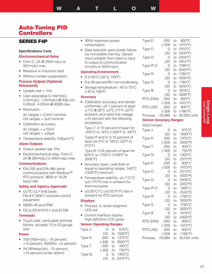
W A T L O W
47
Sin
gle-L
oo
pA
uto
-Tu
nin
g P
ID
SERIES F4P
Auto-Tuning PIDControllers
Electromechanical Relay
• Form C, 2A @ 250VÅ(ac) or30VÎ(dc) max.
• Resistive or inductive load
• Without contact suppression
Process Outputs (OptionalRetransmit)
• Update rate = 1Hz
• User-selectable 0-10VÎ(dc), 0-5VÎ(dc), 1-5VÎ(dc) @1KΩ min.,0-20mA, 4-20mA @ 800Ω max.
• Resolution:
dc ranges = 2.5mV nominalmA ranges = 5µA nominal
• Calibration accuracy:
dc ranges = ±15mVmA ranges = ±30µA
• Temperature stability 100ppm/°C
Alarm Outputs
• Output update rate 1Hz
• Electromechanical relay, Form C,2A @ 30VÎ(dc) or 240VÅ(ac) max.
Communications
• EIA-232 and EIA-485 serialcommunications with Modbus™RTU protocol. 9600 or 19.2K baud rate
Safety and Agency Approvals
• UL®/C-UL® 916-listed, File # E185611 process controlequipment
• NEMA 4X and IP65
• CE to EN 61010-1 and 61326
Terminals
• Touch-safe, removable terminalblocks, accepts 12 to 22-gaugewire
Power
• 100-240VÅ(ac), -15 percent, +10 percent; 50/60Hz, ±5 percent
• 24-28Vı(ac/dc), -15 percent, +10 percent (order option)
• 39VA maximum powerconsumption
• Data retention upon power failurevia nonvolatile memory. Sensorinput isolation from input to inputto output to communicationcircuitry is 500VÅ(ac).
Operating Environment
• 0 to 65°C (32 to 149°F)
• 0 to 90 percent RH, non-condensing
• Storage temperature: -40 to 70°C(-40 to 158°F)
Accuracy
• Calibration accuracy and sensorconformity: ±0.1 percent of span±1°C @ 25°C ±3°C (77°F ±5°F)ambient, and rated line voltage±10 percent with the following exceptions:
Type T: 0.12 percent of span for -200°C to -50°C (-328°F to -58°F)
Types R and S: 0.15 percent ofspan for 0°C to 100°C (32°F to212°F)
Type B: 0.24 percent of span for870°C to 1700°C (1598°F to3092°F)
• Accuracy span: Less than orequal to operating ranges, 540°C(1000°F) minimum
• Temperature stability: ±0.1°C/°C(±0.1°F/°F) rise in ambient forthermocouples
• ±0.05°C/°C (±0.05°F/°F) rise inambient for RTD sensors
Displays
• Process: 5, seven-segment LED red
• Control interface display: high-definition LCD green
Sensor Operating Ranges
Type J: 0 to 815°C(32 to 1500°F)
Type K: -200 to 1370°C(-328 to 2500°F)
Type T: -200 to 400°C(-328 to 750°F)
Type N: 0 to 1300°C(32 to 2372°F)
Type E: -200 to 800°C(-328 to 1470°F)
Type C: 0 to 2315°C(32 to 4200°F)
Type D: 0 to 2400°C(32 to 4352°F)
Type Pt 2: 0 to 1395°C(32 to 2543°F)
Type R: 0 to 1760°C(32 to 3200°F)
Type S: 0 to 1760°C(32 to 3200°F)
Type B: 0 to 1816°C(32 to 3300°F)
RTD (DIN): -200 to 800°C(-328 to 1472°F)
RTD (JIS): -200 to 800°C(-328 to 1166°F)
Process: -19,999 to 30,000 unitsSensor Accuracy Ranges
Input rangesType J: 0 to 815°C
(32 to 1500°F)Type K: -200 to 1370°C
(-328 to 2500°F)Type T: -200 to 400°C
(-328 to 750°F)Type N: 0 to 1300°C
(32 to 2372°F)Type E: -200 to 800°C
(-328 to 1470°F)Type C: 0 to 2315°C
(32 to 4200°F)Type D: 0 to 2400°C
(32 to 4352°F)Type Pt 2: 0 to 1395°C
(32 to 2543°F)Type R: 0 to 1760°C
(32 to 3200°F)Type S: 0 to 1760°C
(32 to 3200°F)Type B: 0 to 1816°C
(32 to 3300°F)RTD (DIN): -200 to 800°C
(-328 to 1472°F)RTD (JIS): -200 to 800°C
(-328 to 1166°F)Process: -19,999 to 30,000 units
Specifications Cont.

48
Auto-Tuning PIDControllersSERIES F4P Ordering Information
To order, complete the code number to the right with the information below:SERIES F4P = 1⁄4 DIN temperature process controller
F4 P - A - SERIES F4P
Temperature/Process Controller Single channel temperature/process controller, two alarms, EIA-232/485 comms, four event inputs
Power SupplyH = 100-240Vı(ac/dc)L = 24-28Vı(ac/dc)
Output 1AC = Open collector/switched dcE = Electromechanical relay, Form C
2 amp without contact suppressionK = Solid state Form A 0.5 amp relay
without contact suppressionF = Process, 0-5, 1-5, 0-10VÎ(dc),
0-20mA, 4-20mA
Output 1BA = NoneE = Electromechanical relay, Form C
2A without contact suppressionC = Open collector/switched dcK = Solid state Form A 0.5 amp relay
without contact suppressionF = Process, 0-5, 1-5, 0-10VÎ(dc),
0-20mA, 4-20mA
Enhanced Control OperationA = Standard control operation B = Enhanced control operation, dual universal
inputs, cascade, ratio, duplex, differential, slidewire
Auxiliary Retransmit Module0 = None1 = Single retransmit output 0-5, 1-5, 0-10VÎ(dc),
0-20mA, 4-20mA2 = Dual retransmit outputs 0-5, 1-5, 0-10VÎ(dc),
0-20mA, 4-20mA
Language and RTD Options1 = English with 100Ω RTD 5 = English with 500 & 1KΩ RTD2 = German with 100Ω RTD 6 = German with 500 & 1KΩ RTD 3 = French with 100Ω RTD 7 = French with 500 & 1KΩ RTD4 = Spanish with 100Ω RTD 8 = Spanish with 500 & 1KΩ RTD
Display and Custom OptionsRG= Red/Green displayXX = Custom options, software, setting parameters, overlays
99.82 mm
108.81 mm (4.824 in.)
(3.930 in.)
99.82 mm (3.930 in.)
(3.622 in. x 3.622 in.)
Panel Cutout92 mm x 92 mm
97.79 mm (3.850 in.)
108.05 mm(4.254 in.)
10.26 mm (.404 in.)
Specifications Cont.
Dimensions
• Width x height x depth
99 mm x 99 mm x 97 mm panelmount (3.93 in. x 3.93 in. x 3.85 in.)
F.O.B.: Winona, Minnesota
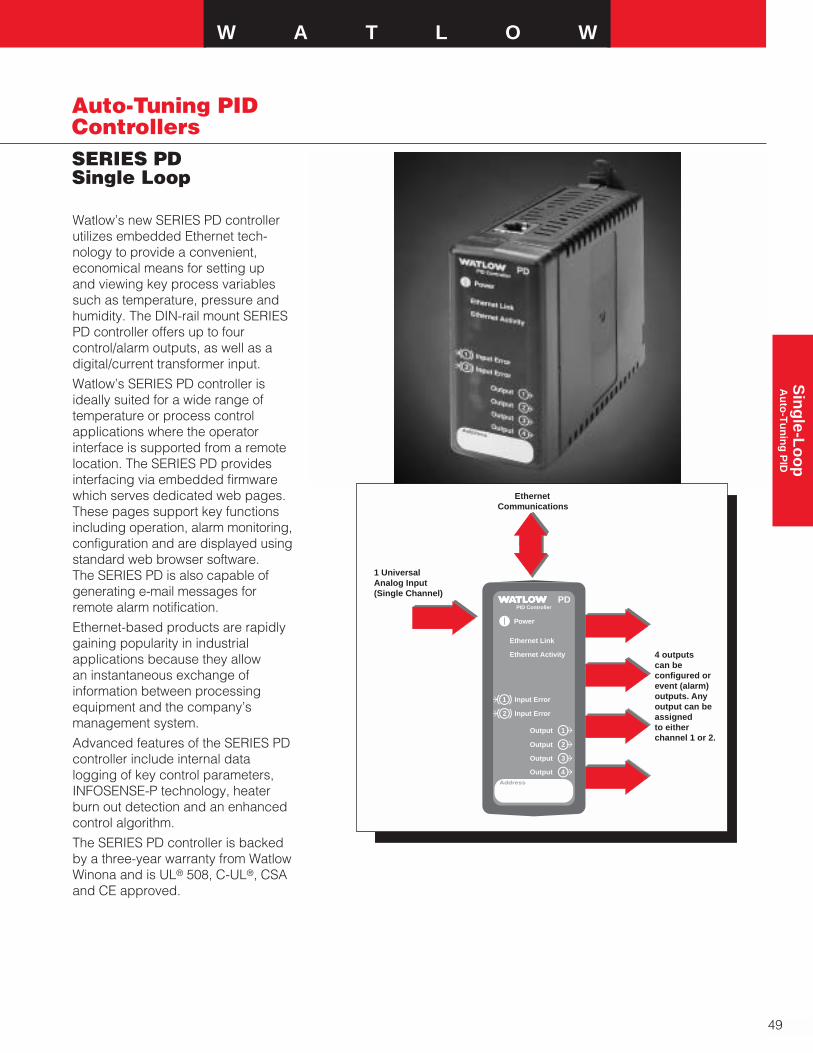
W A T L O W
49
Sin
gle-L
oo
pA
uto
-Tu
nin
g P
ID
SERIES PDSingle Loop
Auto-Tuning PIDControllers
Watlow’s new SERIES PD controllerutilizes embedded Ethernet tech-nology to provide a convenient,economical means for setting up and viewing key process variablessuch as temperature, pressure andhumidity. The DIN-rail mount SERIESPD controller offers up to fourcontrol/alarm outputs, as well as adigital/current transformer input.
Watlow’s SERIES PD controller isideally suited for a wide range oftemperature or process controlapplications where the operatorinterface is supported from a remotelocation. The SERIES PD providesinterfacing via embedded firmwarewhich serves dedicated web pages.These pages support key functionsincluding operation, alarm monitoring,configuration and are displayed usingstandard web browser software.The SERIES PD is also capable ofgenerating e-mail messages forremote alarm notification.
Ethernet-based products are rapidlygaining popularity in industrialapplications because they allowan instantaneous exchange ofinformation between processingequipment and the company’smanagement system.
Advanced features of the SERIES PDcontroller include internal datalogging of key control parameters,INFOSENSE-P technology, heaterburn out detection and an enhancedcontrol algorithm.
The SERIES PD controller is backedby a three-year warranty from WatlowWinona and is UL® 508, C-UL®, CSAand CE approved.
PDPID Controller
Power
Ethernet Link
Ethernet Activity
1
2
3
4
1
2
Input Error
Input Error
Output
Output
Output
OutputAddress
1 UniversalAnalog Input(Single Channel)
4 outputs can beconfigured or event (alarm) outputs. Anyoutput can be assignedto either channel 1 or 2.
Ethernet Communications

50
Auto-Tuning PIDControllersSERIES PDSingle Loop
DIN-rail
146 mm(3.750 in.)
73 mm(2.875 in.)
129 mm(5.062 in.)
Attachment Angle 10°
DIN-rail
Side View
Front View
Bracket for Panel Mounting
(#6 Screwor m3.5 Required)
8 mm(0.318 in.)
107 mm(4.225 in.)
118 mm(4.650 in.)
Min. Clearance 51 mm(2 in.)
Min. ClearanceBetween RailCenterlines
146 mm(5.750 in.)
42 mm(1.637 in.)
42 mm(1.650 in.)
Top/BottomMountHole Offset
PDPID Controller
Power
Ethernet Link
Ethernet Activity
1
1
2
Input Error
Input Error
Output
Output
Output
OutputAddress
PDPID Controller
Power
Ethernet Link
Ethernet Activity
1
2
3
4
1
2
Input Error
Input Error
Output
Output
Output
OutputAddress
PDPID Controller
Power
Ethernet Link
Ethernet Activity
1
2
3
4
1
2
Input Error
Input Error
Output
Output
Output
OutputAddress
4
3
2
Features and Benefits
Ethernet connectivity
• Convenient, easy to use operatorinterface
• Simplified process monitoring
DIN-rail sub panel mounting
• Quick, economic installation
Watlow INFOSENSE™ sensortechnology
• INFOSENSE™ technologyimproves sensor accuracy by aminimum of 50 percent
Advanced control algorithm
• Tighter process control
Heater burn out detection
• Improved process yields
Internal data logging
• Reduces external hardwaredemands
Virtual or hardware alarms with e-mail delivery
• Remote alarm notification

W A T L O W
51
Sin
gle-L
oo
pA
uto
-Tu
nin
g P
ID
SERIES PDSingle Loop
Auto-Tuning PIDControllers
Specifications
Power
• 24Vı(ac/dc), +10/-15 percent,50/60Hz, ±5 percent
• 12VA maximum powerconsumption
• Data retention upon power failurevia nonvolatile memory
Environment
• 0 to 65°C (32 to 149°F) operatingtemperature
• -40 to 85°C (-40 to 185°F) storagetemperature
• 0 to 90 percent RH, non-condensing
Accuracy
• Calibration accuracy and sensorconformity: ±0.1 percent of span,±1°C @ the calibrated ambienttemperature and rated line voltage
• Calibration ambient temperature= 25°C ±3°C (77°F ±5°F)
• Accuracy span: 540°C (1000°F)minimum
• Temperature stability: ±0.1°C/°C(±0.2°F/°F) rise in ambientmaximum
Agency Approvals
• UL® 508, C-UL®, CSA and CE
Controller
• Microprocessor based user-selectable control modes
• Single or dual channel universalinputs
• Current transformer inputs/digitalinputs
• Up to four programmable outputs
• Update rates, inputs = 10Hz,outputs = 10Hz
Operator Interface
• Browser based HMI (HumanMachine Interface)
Wiring Termination
• Touch safe removable terminals
• 14 to 22 AWG
Universal Inputs (Electrically Isolated)
• Thermocouple, grounded orungrounded sensors
• RTD 2-or 3-wire, platinum, 100Ω @ 0°C calibration to DIN-curve (0.00385 Ω/Ω/°C)
• Process 0-20mA @ <100Ω, or 0-10VÎ(dc) @ 10kΩ inputimpedance (50,000 bits @full scale)
Digital Inputs
• Contact or dc voltage
• 10KΩ input impedance
Current Transformer Inputs
• 0 to 50mA CT input into 100Ωimpedance
Allowable Input Operating RangeType J: -200 to 1200°C
(-328 to 2192°F)Type K: -270 to 1370°C
(-454 to 2500°F)Type T: -270 to 400°C
(-454 to 750°F)Type N: -270 to 1300°C
(-454 to 2372°F)Type E: -270 to 975°C
(-454 to 1790°F)Type C: 0 to 2315°C
(32 to 4200°F)Type D: 0 to 2315°C
(32 to 4200°F)Type PTII: 0 to 1395°C
(32 to 2543°F)Type R: 0 to 1760°C
(32 to 3200°F)Type S: 0 to 1760°C
(32 to 3200°F)Type B: 0 to 1815°C
(32 to 3300°F)RTD (DIN): -200 to 800°C
(-328 to 1470°F)Process V: 0 to 10VÎ(dc)Process I: 0 to 20mA
Control/Alarm Outputs (1 - 4)
• User selectable as: on-off, P, PI,PD, PID, heat, cool, alarm actionor retransmit with process outputtype hardware
• Open collector/switched dc
• Open collector 42VÎ(dc)maximum @ 0.5A
• Switched dc 22 to 28VÎ(dc)limited @ 30mA
• Solid state relay, Form A, 0.5A @24VÅ(ac) minimum, 264VÅ(ac)maximum, opto-isolated, withoutcontact suppression
• User-selectable 0-10VÎ(dc), 1KΩminimum, scalable, 0-20mA @800Ω maximum, scalable
• Electromechanical relay. Form C,rated 5A @ 120VÅ(ac) or 5A @240VÅ(ac) or 5A @ 30VÎ(dc)
Communications
• TCP/IP/Ethernet
• Modbus™ TCP
• Ethernet RJ 45 connector, 10 base T
• HTTP interface
• DHCP, auto IP or fixed IP address
Dimensions
• Width x height x depth
42 mm x 116 mm x 132 mm (1.64 in. x 4.56 in. x 5.19 in.) DIN-rail or chassis mount, DIN-railspec DIN 5022 35 mm x 7.5 mm (1.38 in. x 0.30 in.)
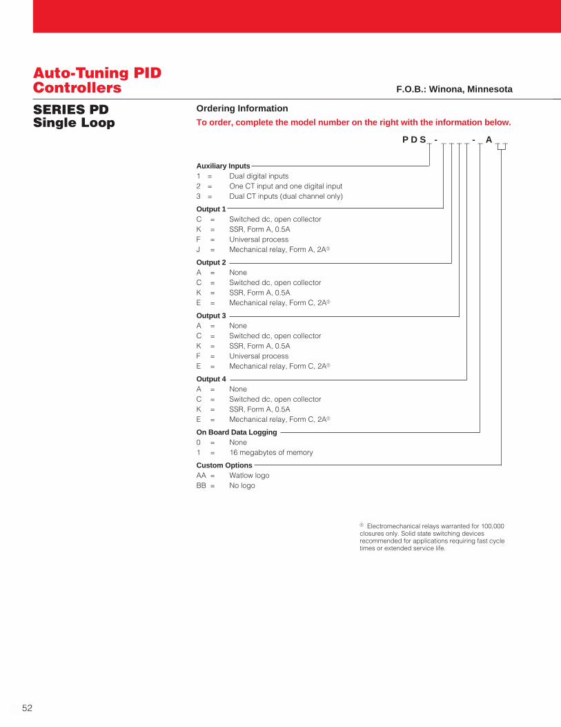
52
Auto-Tuning PIDControllersSERIES PDSingle Loop
Ordering Information
To order, complete the model number on the right with the information below.
P D S_ - _ _ _ _ - _ A _ _
Auxiliary Inputs1 = Dual digital inputs2 = One CT input and one digital input3 = Dual CT inputs (dual channel only)
Output 1C = Switched dc, open collectorK = SSR, Form A, 0.5AF = Universal processJ = Mechanical relay, Form A, 2Aa
Output 2A = NoneC = Switched dc, open collectorK = SSR, Form A, 0.5AE = Mechanical relay, Form C, 2Aa
Output 3 A = NoneC = Switched dc, open collectorK = SSR, Form A, 0.5AF = Universal processE = Mechanical relay, Form C, 2Aa
Output 4A = NoneC = Switched dc, open collectorK = SSR, Form A, 0.5AE = Mechanical relay, Form C, 2Aa
On Board Data Logging0 = None1 = 16 megabytes of memory
Custom OptionsAA = Watlow logoBB = No logo
F.O.B.: Winona, Minnesota
a Electromechanical relays warranted for 100,000closures only. Solid state switching devicesrecommended for applications requiring fast cycletimes or extended service life.
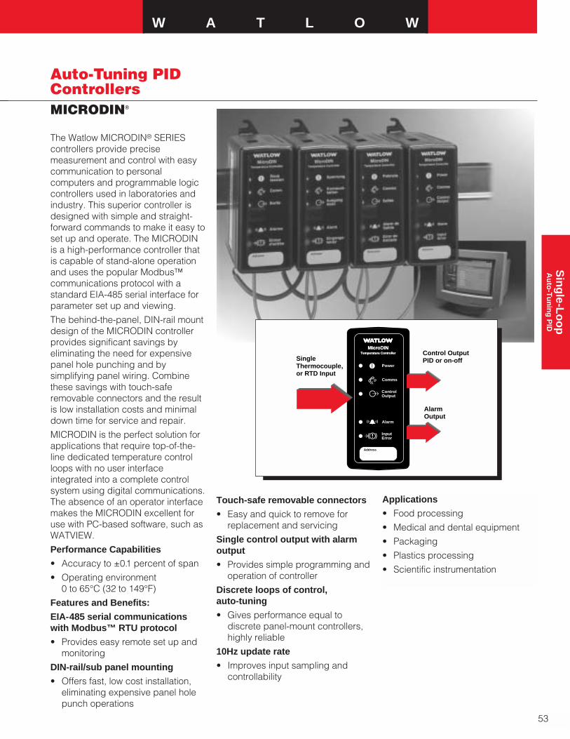
W A T L O WS
ing
le-Lo
op
Au
to-T
un
ing
PID
Auto-Tuning PIDControllers
53
MICRODIN®
The Watlow MICRODIN® SERIEScontrollers provide precisemeasurement and control with easycommunication to personalcomputers and programmable logiccontrollers used in laboratories andindustry. This superior controller isdesigned with simple and straight-forward commands to make it easy toset up and operate. The MICRODINis a high-performance controller thatis capable of stand-alone operationand uses the popular Modbus™communications protocol with astandard EIA-485 serial interface forparameter set up and viewing.
The behind-the-panel, DIN-rail mountdesign of the MICRODIN controllerprovides significant savings byeliminating the need for expensivepanel hole punching and bysimplifying panel wiring. Combinethese savings with touch-saferemovable connectors and the resultis low installation costs and minimaldown time for service and repair.
MICRODIN is the perfect solution forapplications that require top-of-the-line dedicated temperature controlloops with no user interfaceintegrated into a complete controlsystem using digital communications.The absence of an operator interfacemakes the MICRODIN excellent foruse with PC-based software, such asWATVIEW.
Performance Capabilities
• Accuracy to ±0.1 percent of span
• Operating environment 0 to 65°C (32 to 149°F)
Features and Benefits:
EIA-485 serial communicationswith Modbus™ RTU protocol
• Provides easy remote set up andmonitoring
DIN-rail/sub panel mounting
• Offers fast, low cost installation,eliminating expensive panel holepunch operations
Touch-safe removable connectors
• Easy and quick to remove forreplacement and servicing
Single control output with alarmoutput
• Provides simple programming andoperation of controller
Discrete loops of control, auto-tuning
• Gives performance equal todiscrete panel-mount controllers,highly reliable
10Hz update rate
• Improves input sampling andcontrollability
Applications
• Food processing
• Medical and dental equipment
• Packaging
• Plastics processing
• Scientific instrumentation
Single Thermocouple, or RTD Input
Control OutputPID or on-off
AlarmOutput
Address
Power
Comms
Alarm
Temperature Controller
MicroDINTemperature Controller
MicroDIN
ControlOutput
InputError

Auto-Tuning PIDControllersMICRODIN
54
Specifications
Control Mode
• Microprocessor-based, userselectable control modes
• Single input, single output
• Heat or cool auto-tuning
Agency Approvals
• UL®, C-UL® 508 recognized, File#E102269 Industrial ControlEquipment
• CE to EN 61010
Operator Interface
• EIA-485 serial communicationswith Modbus™ RTU protocol
• 9600, 19200 user selectable baudrates
• One to 63 user selectableaddress range
Accuracy
• Calibration accuracy and sensorconformity: ±0.1 percent of span 25°C ±3°C (±1 @ 77°F ±5˚F)ambient, and rated line voltage±10 percent with the followingexceptions:
Type T: 0.12 percent of span for -200°C to -50°C (-328°F to -58°F)
Types R and S: 0.15 percent ofspan for 0°C to 100°C (32°F to212°F)
Type B: 0.24 percent of span for870°C to 1700°C (1598°F to3092°F)
• Accuracy span: Less than orequal to operating ranges, 540°C(1000°F) minimum
• Temperature stability: ±0.2°C/°C(±0.2°F/°F) rise in ambientmaximum for thermocouples,±0.05°C/°C (±0.05°F/°F) rise inambient maximum for RTD sensors
• Voltage stability: ±0.01 percent of span per percent of rated linevoltage
Sensors Inputs
• Sensor input sampling rate: 10 samples/second 10Hz
• Thermocouple, grounded orungrounded sensors
• RTD 2- or 3-wire, platinum, 100Ω @0˚C calibration to JIS curve(0.003916Ω/Ω/°C) or DIN-curve(0.00385Ω/Ω/°C)
• Sensor break protection de-energizes control output to protectsystem or selectable bumplesstransfer to manual operation
• °F or °C, user selectable
• Sensor operating ranges:
Type B T/C 0 to 1816°C(32 to 3300°F)
Type C (W5) T/C 0 to 2315°C(32 to 4200°F)
Type D (W3) T/C 0 to 2315°C(32 to 4200°F)
Type E T/C -200 to 800°C(-328 to 1472°F)
Type J T/C 0 to 815°C(32 to 1382°F)
Type K T/C -200 to 1370°C(-328 to 2500°F)
Type N T/C 0 to 1300°C(32 to 2372°F)
Pt 2 0 to 1395°C(32 to 2543°F)
Type R T/C 0 to 1760°C(32 to 3200°F)
Type S T/C 0 to 1760°C(32 to 3200°F)
Type T T/C -200 to 400°C(-328 to 750°F)
RTD (DIN) -200 to 800°C(-328 to 1472°F)
RTD (JIS) -200 to 630°C(-328 to 1166°F)
• Tenth degree resolutionselectable over sensor operatingrange within limits of -199.9 to999.9, except for thermocoupleTypes B, R and S
Output 1: User selectable
• On-off; P, PI, PD, PID heat or coolaction adjustable switchingdifferential: 1 to 9999 or 0.1 to999.9 °C or °F
• Proportional band: 0 to 9999, or0.0 to 999.9 °C or °F
• Integral: 0.00 to 99.99 minutes perrepeat
• Reset: 0.00 to 99.99 repeats perminute
• Derivative/rate: 0.00 to 9.99 minutes
• Cycle time: 0.1 to 60.0 seconds
Output 2: User selectable
• Process or deviation alarm withflashing alarm status indicator
• Alarm with separate high and lowset points
• Hysteresis: 1 to 9999° switchingdifferential
Primary Control Output (heating or cooling)
• Output update rate: 10 persecond, 10Hz (maximum)
• Internal load switching (nominal):Switched dc (isolated) signal, 22 to28VÎ(dc), current limited @ 30mA
• Overload current and short circuitprotection
• External load switching(maximum): Open collector up to42VÎ(dc) @ 1A with externalpower supply
Alarm Output:
• Output update rate 2 per second(2Hz)
• Electromechanical relay, Form A,2A @ 30VÎ(dc) or 240VÅ(ac),
• Alarm output can be latching ornon-latching, and process ordeviation with separate high andlow values. Alarm silencing (inhibit)on power-up
Electromagnetic Compatibility and Immunity
• Complies with EN 50081, EN 50082
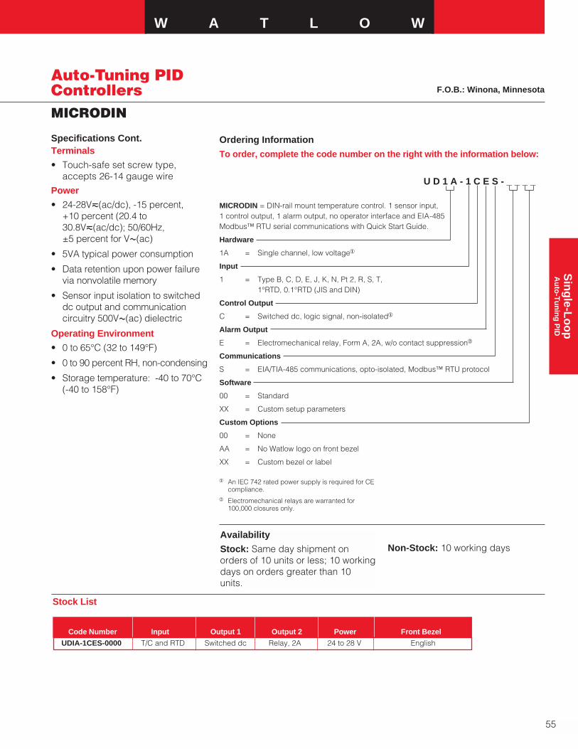
W A T L O WS
ing
le-Lo
op
Au
to-T
un
ing
PID
MICRODIN
Auto-Tuning PIDControllers
55
Ordering Information
To order, complete the code number on the right with the information below:
U D 1 A - 1 C E S - _ _ _ _
MICRODIN = DIN-rail mount temperature control. 1 sensor input,1 control output, 1 alarm output, no operator interface and EIA-485 Modbus™ RTU serial communications with Quick Start Guide.
Hardware
1A = Single channel, low voltage1
Input
1 = Type B, C, D, E, J, K, N, Pt 2, R, S, T, 1°RTD, 0.1°RTD (JIS and DIN)
Control Output
C = Switched dc, logic signal, non-isolated1
Alarm Output
E = Electromechanical relay, Form A, 2A, w/o contact suppression2
Communications
S = EIA/TIA-485 communications, opto-isolated, Modbus™ RTU protocol
Software
00 = Standard
XX = Custom setup parameters
Custom Options
00 = None
AA = No Watlow logo on front bezel
XX = Custom bezel or label
Availability
Stock: Same day shipment onorders of 10 units or less; 10 workingdays on orders greater than 10units.
F.O.B.: Winona, Minnesota
Terminals
• Touch-safe set screw type,accepts 26-14 gauge wire
Power
• 24-28V‡(ac/dc), -15 percent, +10 percent (20.4 to30.8V‡(ac/dc); 50/60Hz, ±5 percent for VÅ(ac)
• 5VA typical power consumption
• Data retention upon power failurevia nonvolatile memory
• Sensor input isolation to switcheddc output and communicationcircuitry 500VÅ(ac) dielectric
Operating Environment
• 0 to 65°C (32 to 149°F)
• 0 to 90 percent RH, non-condensing
• Storage temperature: -40 to 70°C(-40 to 158°F)
2 Electromechanical relays are warranted for100,000 closures only.
1 An IEC 742 rated power supply is required for CEcompliance.
Non-Stock: 10 working days
UDIA-1CES-0000 T/C and RTD Switched dc Relay, 2A 24 to 28 V English
Stock List
Code Number Input Output 1 Output 2 Power Front Bezel
Specifications Cont.
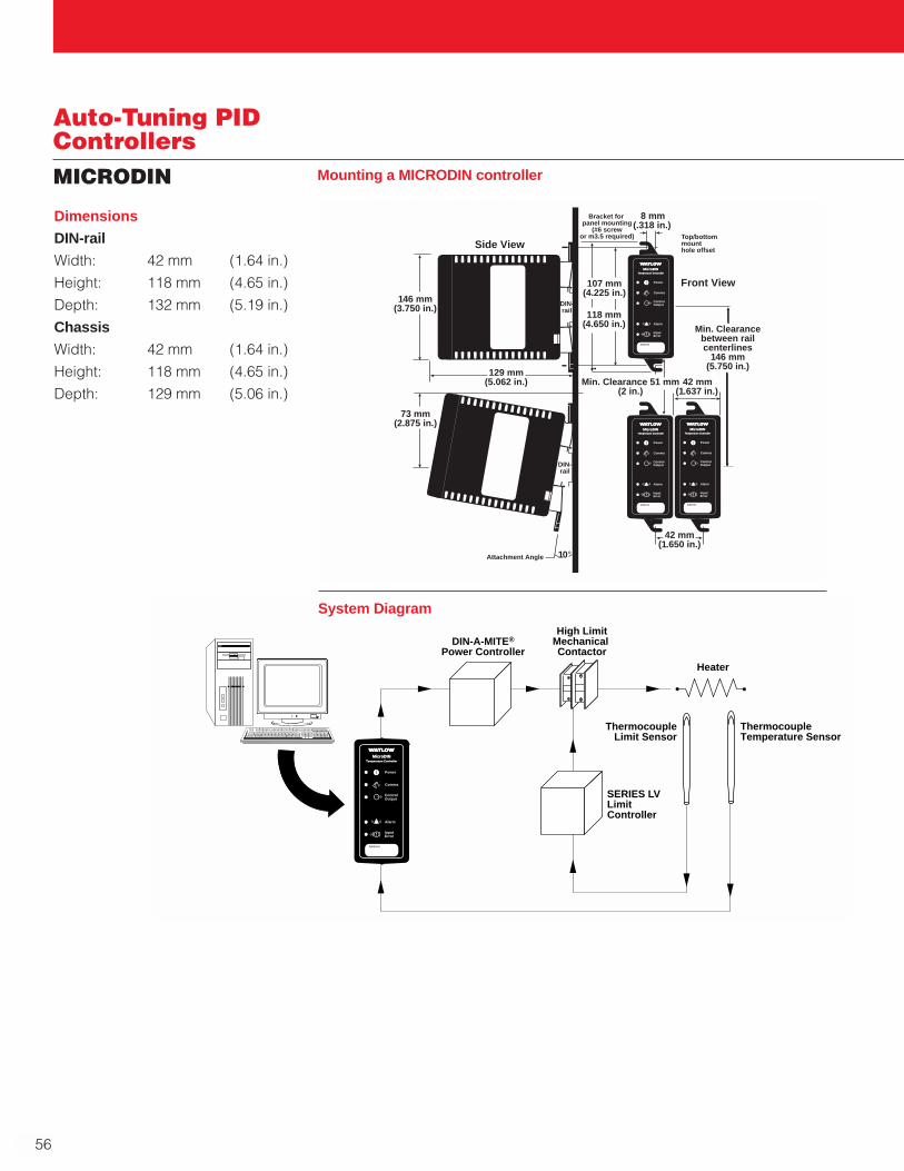
Auto-Tuning PIDControllersMICRODIN
56
Dimensions
DIN-rail
Width: 42 mm (1.64 in.)
Height: 118 mm (4.65 in.)
Depth: 132 mm (5.19 in.)
Chassis
Width: 42 mm (1.64 in.)
Height: 118 mm (4.65 in.)
Depth: 129 mm (5.06 in.)
DIN-A-MITE®
Power Controller
High LimitMechanical Contactor
Heater
ThermocoupleLimit Sensor
ThermocoupleTemperature Sensor
SERIES LVLimit Controller
Address
Power
Comms
Alarm
Temperature Controller
MicroDINTemperature Controller
MicroDIN
ControlOutput
InputError
System Diagram
DIN-rail
Bracket for panel mounting
(#6 screwor m3.5 required)
Front View
8 mm(.318 in.)
Address
Power
Comms
Alarm
Temperature Controller
MicroDINTemperature Controller
MicroDIN
ControlOutput
InputError
146 mm(3.750 in.)
73 mm(2.875 in.)
129 mm(5.062 in.)
Attachment Angle 10°
DIN-rail
Address
Power
Comms
Alarm
Temperature Controller
MicroDINTemperature Controller
MicroDIN
ControlOutput
InputError
Address
Power
Comms
Alarm
Temperature Controller
MicroDINTemperature Controller
MicroDIN
ControlOutput
InputError
Min. Clearance 51 mm(2 in.)
Min. Clearancebetween railcenterlines
146 mm(5.750 in.)
42 mm(1.637 in.)
42 mm(1.650 in.)
Top/bottommounthole offset
107 mm(4.225 in.)
118 mm(4.650 in.)
Side View
Mounting a MICRODIN controller
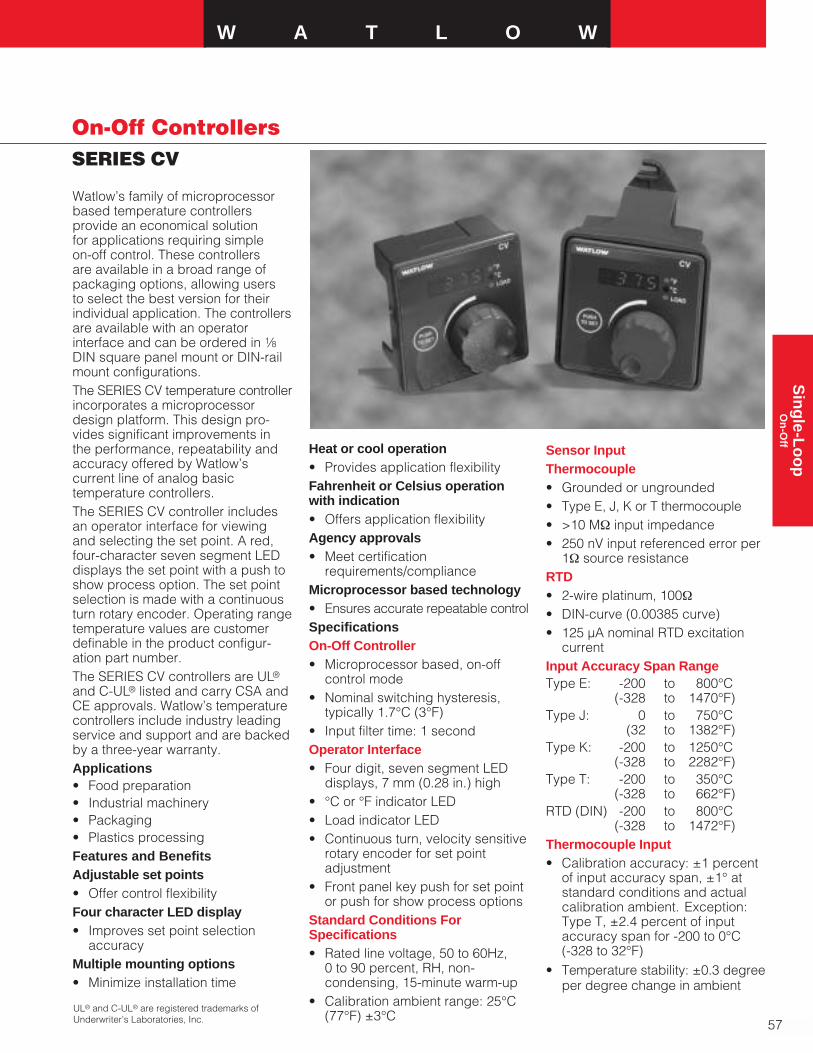
W A T L O W
57
Sin
gle-L
oo
pO
n-O
ff
SERIES CV
On-Off Controllers
Watlow’s family of microprocessorbased temperature controllersprovide an economical solution for applications requiring simple on-off control. These controllers are available in a broad range ofpackaging options, allowing users to select the best version for theirindividual application. The controllersare available with an operatorinterface and can be ordered in 1⁄8DIN square panel mount or DIN-railmount configurations.The SERIES CV temperature controllerincorporates a microprocessordesign platform. This design pro-vides significant improvements in the performance, repeatability andaccuracy offered by Watlow’scurrent line of analog basictemperature controllers.The SERIES CV controller includesan operator interface for viewingand selecting the set point. A red,four-character seven segment LEDdisplays the set point with a push toshow process option. The set pointselection is made with a continuousturn rotary encoder. Operating rangetemperature values are customerdefinable in the product configur-ation part number.The SERIES CV controllers are UL®
and C-UL® listed and carry CSA andCE approvals. Watlow’s temperaturecontrollers include industry leadingservice and support and are backedby a three-year warranty.Applications• Food preparation• Industrial machinery• Packaging• Plastics processingFeatures and BenefitsAdjustable set points• Offer control flexibility Four character LED display• Improves set point selection
accuracyMultiple mounting options• Minimize installation time
Heat or cool operation• Provides application flexibilityFahrenheit or Celsius operationwith indication• Offers application flexibilityAgency approvals• Meet certification
requirements/complianceMicroprocessor based technology• Ensures accurate repeatable controlSpecificationsOn-Off Controller • Microprocessor based, on-off
control mode• Nominal switching hysteresis,
typically 1.7°C (3°F)• Input filter time: 1 secondOperator Interface• Four digit, seven segment LED
displays, 7 mm (0.28 in.) high• °C or °F indicator LED• Load indicator LED• Continuous turn, velocity sensitive
rotary encoder for set pointadjustment
• Front panel key push for set pointor push for show process options
Standard Conditions ForSpecifications• Rated line voltage, 50 to 60Hz,
0 to 90 percent, RH, non-condensing, 15-minute warm-up
• Calibration ambient range: 25°C(77°F) ±3°C
Sensor InputThermocouple• Grounded or ungrounded• Type E, J, K or T thermocouple• >10 MΩ input impedance• 250 nV input referenced error per
1Ω source resistanceRTD• 2-wire platinum, 100Ω• DIN-curve (0.00385 curve) • 125 µA nominal RTD excitation
currentInput Accuracy Span RangeType E: -200 to 800°C
(-328 to 1470°F)Type J: 0 to 750°C
(32 to 1382°F)Type K: -200 to 1250°C
(-328 to 2282°F) Type T: -200 to 350°C
(-328 to 662°F)RTD (DIN) -200 to 800°C
(-328 to 1472°F)Thermocouple Input• Calibration accuracy: ±1 percent
of input accuracy span, ±1° atstandard conditions and actualcalibration ambient. Exception:Type T, ±2.4 percent of inputaccuracy span for -200 to 0°C (-328 to 32°F)
• Temperature stability: ±0.3 degreeper degree change in ambient
UL® and C-UL® are registered trademarks ofUnderwriter’s Laboratories, Inc.

58
On-Off ControllersSERIES CV
RTD Input• Calibration accuracy ±1 percent
of input accuracy span ±1° atstandard conditions and actualcalibration ambient
• Temperature stability: ±0.2 degreeper degree change in ambient
Allowable Operating RangesType E: -200 to 800°C
(-328 to 1470°F) Type J: -210 to 1038°C
(-346 to 1900°F)Type K: -270 to 1370°C
(-454 to 2500°F)Type T: -270 to 400°C
(-454 to 750°F)RTD (DIN) -200 to 800°C
(-328 to 1472°F)Output TypesSwitched dc (non-isolated) • Supply voltage maximum:
24VÎ(dc) into an infinite load• Supply voltage minimum: 5VÎ(dc)
at 10mA• Minimum load impedance: 500ΩElectromechanical Relay, Form C• Minimum load current: 100mA• 8 A @ 240VÅ(ac) or 30VÎ(dc)
maximum, resistive• 250VA pilot duty, 120/240VÅ(ac)
maximum, inductive• Use RC suppression for inductive
loads• Electrical life 100,000 cycles at
rated currentAgency Approvals• UL® 60730-1 Recognized
Temperature Controller andIndicator
• UL® 197 Reviewed for Use inCooking Appliances
• ANSI Z21.23 Gas ApplianceThermostat Approval
• Temperature Control andIndicator CSA 22.2 No. 24
Specifications Cont.
Terminals• 6.3 mm (0.25 in.) quick connect,
push on terminalPower• 24VÅ(ac) +10 percent; -15
percent; 50/60Hz, ±5 percent• 120VÅ(ac) +10 percent; -15
percent; 50/60Hz, ±5 percent• 230 to 240VÅ(ac) +10 percent;
-15 percent; 50/60Hz, ±5 percent• 10VA maximum power consumption• Data retention upon power failure
via nonvolatile memory
DIN-rail 78.1 mm 112.3 mm 90.7 mm(3.08 in.) (4.42 in.) (3.57 in.)
Square 1⁄8 72.4 mm 72.4 mm Behind panelDIN-panel (2.85 in.) (2.85 in.) 51.7 mm
(2.04 in.)
Style Width Height Depth
Operating Environment• 0 to 70°C (32 to 158°F)• 0 to 90 percent RH, non-condensing• Storage temperature: -40 to 85°C
(-40 to 185°F)Dimensions• DIN-rail model can be DIN-rail or
chassis mountDIN-rail spec DIN 50022, 35 mm x7.5 mm (1.38 in. x 0.30 in.)
Ordering Information
To order, complete the model number on the right with the information below.C V
SERIES CV = On-off controller rotary set point adjustment,four character, seven segment displayPower SupplyB = 120VÅ(ac), switched dc outputC = 120VÅ(ac), eight amp relay outputD = 230 to 240VÅ(ac), switched dc outputE = 230 to 240VÅ(ac), eight amp relay outputF = 24VÅ(ac), switched dc outputG = 24VÅ(ac), eight amp relay outputPackage1 = Panel mount square 1⁄8 DIN2 = DIN-rail mountSensor Type and ScaleH = T/C Type J Fahrenheit (-346 to 1900˚F)J = T/C Type J Celsius (-210 to 1038˚C)K = T/C Type K Fahrenheit (-454 to 2500˚F)L = T/C Type K Celsius (-270 to 1370˚C)M = T/C Type T Fahrenheit (-454 to 750˚F)N = T/C Type T Celsius (-270 to 400˚C)P = RTD Fahrenheit (-328 to 1472˚F)R = RTD Celsius (-200 to 800˚C)S = T/C Type E Fahrenheit (-328 to 1470˚F)T = T/C Type E Celsius (-200 to 800˚C)Control TypeH = Heat C = Cool Low Set Point Operating Range Value1
High Set Point Operating Range Value1
Overlay/Customs OptionsA = StandardB = Push to show processC = Push to adjust set point1A (-) is used in the left most digit of the set point operating ranges to indicates a negativetemperature value
F.O.B.: Winona, Minnesota
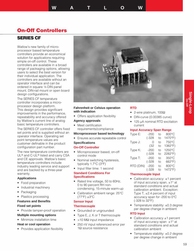
W A T L O W
59
Sin
gle-L
oo
pO
n-O
ff
SERIES CF
On-Off Controllers
Watlow’s new family of micro-processor based temperaturecontrollers provide an economicalsolution for applications requiringsimple on-off control. Thesecontrollers are available in a broadrange of packaging options, allowingusers to select the best version fortheir individual application. Thecontrollers are available without anoperator interface and can beordered in square 1⁄8 DIN panelmount, DIN-rail mount or open boarddesign configurations.The SERIES CF temperaturecontroller incorporates a micro-processor design platform. This design provides significantimprovements in the performance,repeatability and accuracy offeredby Watlow’s current line of analogbasic temperature controllers. The SERIES CF controller offers fixedset points and is supplied without anoperator interface. Operating setpoint temperature values arecustomer definable in the productconfiguration part number.The new temperature controllers areUL® and C-UL® listed and carry CSAand CE approvals. Watlow’s basictemperature controllers includeindustry leading service and supportand are backed by a three-yearwarranty. Applications• Food preparation• Industrial machinery• Packaging• Plastics processingFeatures and BenefitsFixed set points• Provide tamper-proof operationMultiple mounting options• Minimize installation timeHeat or cool operation• Provides application flexibility
Fahrenheit or Celsius operationwith indication• Offers application flexibilityAgency approvals• Meet certification
requirements/complianceMicroprocessor based technology• Ensures accurate repeatable controlSpecificationsOn-Off Controller • Microprocessor based, on-off
control mode• Nominal switching hysteresis,
typically 1.7°C (3°F)• Input filter time: 1 secondStandard Conditions ForSpecifications• Rated line voltage, 50 to 60Hz,
0 to 90 percent RH non-condensing, 15-minute warm-up
• Calibration ambient range: 25°C(77°F) ±3°C
Sensor InputThermocouple• Grounded or ungrounded• Type E, J, K or T thermocouple• >10 MΩ input impedance• 250 nV input referenced error per
1Ω source resistance
RTD• 2-wire platinum, 100Ω• DIN-curve (0.00385 curve) • 125 µA nominal RTD excitation
currentInput Accuracy Span RangeType E: -200 to 800°C
(-328 to 1470°F)Type J: 0 to 750°C
(32 to 1382°F)Type K: -200 to 1250°C
(-328 to 2282°F) Type T: -200 to 350°C
(-328 to 662°F)RTD (DIN) -200 to 800°C
(-328 to 1472°F)Thermocouple Input• Calibration accuracy: ±1 percent
of input accuracy span, ±1° atstandard conditions and actualcalibration ambient. Exception:Type T, ±2.4 percent of inputaccuracy span for -200 to 0°C (-328 to 32°F)
• Temperature stability: ±0.3 degreeper degree change in ambient
RTD Input• Calibration accuracy ±1 percent
of input accuracy span ±1° atstandard conditions and actualcalibration ambient
• Temperature stability: ±0.2 degreeper degree change in ambient

60
On-Off ControllersSERIES CF
Allowable Operating RangesType E: -200 to 800°C
(-328 to 1470°F) Type J: -210 to 1038°C
(-346 to 1900°F)Type K: -270 to 1370°C
(-454 to 2500°F)Type T: -270 to 400°C
(-454 to 750°F)RTD (DIN) -200 to 800°C
(-328 to 1472°F)Output TypesSwitched dc (non-isolated)• Supply voltage maximum:
24VÎ(dc) into an infinite load• Supply voltage minimum: 5VÎ(dc)
at 10mA• Minimum load impedance: 500ΩElectromechanical Relay, Form C• Minimum load current: 100mA• 8 A @ 240VÅ(ac) or 30VÎ(dc)
maximum, resistive• 250VA pilot duty, 120/240VÅ(ac)
maximum, inductive• Use RC suppression for inductive
loads• Electrical life 100,000 cycles at
rated currentAgency Approvals• UL® 60730-1 Recognized
Temperature Controller andIndicator
• UL® 197 Reviewed for Use inCooking Appliances
• ANSI Z21.23 Gas ApplianceThermostat Approval
• Temperature Control andIndicator CSA 22.2 No. 24
Terminals• 6.3 mm (0.25 in.) quick connect,
push on terminal
Power• 24VÅ(ac) +10 percent; -15
percent; 50/60Hz, ±5 percent• 120VÅ(ac) +10 percent; -15
percent; 50/60Hz, ±5 percent• 230 to 240VÅ(ac) +10 percent;
-15 percent; 50/60Hz, ±5 percent• 10VA maximum power
consumption• Data retention upon power failure
via nonvolatile memory
Operating Environment• 0 to 70°C (32 to 158°F)• 0 to 90 percent RH, non-condensing• Storage temperature: -40 to 85°C
(-40 to 185°F)Dimensions• DIN-rail model can be DIN-rail or
chassis mountDIN-rail spec DIN 50022, 35 mm x7.5 mm (1.38 in. x 0.30 in.)
Ordering Information
To order, complete the model number on the right with the information below.C F A A A A
SERIES CF = On-off controller, fixed set point, no user interfacePower SupplyB = 120VÅ(ac), switched dc outputC = 120VÅ(ac), eight amp relay outputD = 230 to 240VÅ(ac), switched dc outputE = 230 to 240VÅ(ac), eight amp relay outputF = 24VÅ(ac), switched dc outputG = 24VÅ(ac), eight amp relay outputPackage1 = Panel mount square 1⁄8 DIN2 = DIN-rail mount3 = Open board, non potted4 = Potted caseSensor Type and ScaleH = T/C Type J Fahrenheit (-346 to 1900˚F)J = T/C Type J Celsius (-210 to 1038˚C)K = T/C Type K Fahrenheit (-454 to 2500˚F)L = T/C Type K Celsius (-270 to 1370˚C)M = T/C Type T Fahrenheit (-454 to 750˚F)N = T/C Type T Celsius (-270 to 400˚C)P = RTD Fahrenheit (-328 to 1472˚F)R = RTD Celsius (-200 to 800˚C)S = T/C Type E Fahrenheit (-328 to 1470˚F)T = T/C Type E Celsius (-200 to 800˚C)Control TypeH = Heat C = CoolFixed Set Point Temperature Value1
Overlay/Customs OptionsA = Standard1A (-) is used in the left most digit of the fixed set point indicates a negative temperature value
Open Board 61.7 mm 61.7 mm 45.1 mm(2.43 in.) (2.43 in.) (1.78 in.)
Potted 70.1 mm 102.9 mm 46.6 mm(2.76 in.) (4.05 in.) (1.84 in.)
DIN-Rail 78.1 mm 112.3 mm 90.7 mm(3.08 in.) (4.42 in.) (3.57 in.)
Square 1⁄8 72.4 mm 72.4 mm Behind panelDIN-panel (2.85 in.) (2.85 in.) 51.7 mm
(2.04 in.)
Style Width Height Depth
Specifications Cont.
F.O.B.: Winona, Minnesota

W A T L O W
61
Sin
gle-L
oo
pO
n-O
ff
SERIES 80M6
On-Off Controllers
Watlow’s SERIES 80M6 temperaturecontrollers provide an economical,easy to install unit for temperaturesensing and control in a spacesaving package. The SERIES 80M6delivers single zone, on-off heatingcontrol and is available in threetemperature ranges. The controllerfeatures open sensor and positiveoff circuit protection, preventingheating once the sensor temperaturefalls below the low end of the setpoint range.
The SERIES 80M6 consists of atemperature controller along with arelay output potted in a rugged,plastic shell. This feature makes theSERIES 80M6 ideal for foodserviceand other applications requiringrugged construction.
With 6.35 mm (0.25 in.) quickconnect terminals for thermocoupleinput, power input and relay outputas well as a sub-panel mount, theSERIES 80M6 also allows for simple,quick installation. The SERIES 80M6provides the convenience ofprecision temperature control withthe turn of a potentionmeter and fitswithin the same footprint as thecurrent Watlow 80M5.
The SERIES 80M6 controller isbacked by a 12-month warranty fromWatlow Winona and is UL® 873 andC-UL® recognized.
Applications
• Proofers
• Ovens
• Deep Fryers
• Griddles
• General heating applications
Features and Benefits
Potted shell design
• Safe for use in variousenvironmental conditions
Compact size
• Easily retrofittable to the current80M5
• Space-saving replacement forfilled-bulb controllers
Open sensor protection
• Contacts de-energize in the eventof an open sensor, turning offpower to the load and preventinga runaway
Quick connect terminals
• Fast, easy installation
On-off control
• Provides simple, reliableoperation
Specifications
Control Mode
• On-off control with a -16˚C (4˚F)switching hysteresis for Type E thermocouple
Operator Interface
• Remote set point potentiometer -user mounted potentiometerprovides set point adjustment andindication
• User provided dial scale
Input
• Type E thermocouple
• Sensor may be isolated orgrounded
• Sensor break protection de-energized output
Output
• Electromechanical relay, SPST,sealed, 24VÎ(dc), 30A @120VÅ(ac), 30A @ 240VÅ(ac) UL® rated

62
On-Off ControllersSERIES 80M6
Power
• Nominal voltage - 120 VRMS +10 percent, -15 percent (102 to132VÅ(ac)), 240VRMS +10percent, -15 percent (204 to264VÅ(ac))
• Power requirements - 4.0 VAnominal
• Frequency - 47 to 63Hz (50Hz ±5 percent and 60Hz ±5 percent)
Operating Environment
• Operating temperature up to -0 to 55˚C (32 to 131˚F)
• 0 - 90 percent RH, non-condensing
• Shipping and storagetemperature, 40 to 70˚C (104 to 158˚F)
Dimensions
Control
• Length: 112.5 mm (4.428 in.)
• Width: 91.8 mm (3.615 in.)
• Height: 38.1 mm (1.500 in.)
• Weight: 0.3402 kg (0.75 lb)
Set Pot Assembly
• Pot depth behind: 12.7 mm (0.5 in.)
• Shaft depth in front: 25.4 mm (1.0 in.)
• Lead length: 1066.8 mm (42 in.)
• Weight: 0.01 kg (0.03 lb)
Agency Approvals
• UL® 873 and C-UL® recognized
Terminals
• Quick connects, 6.4 mm (0.25 in.)
Accuracy
• Calibration accuracy ±10˚F
• 120VÅ(ac) line, 102 min, 132 max, VRMS
Specifications Cont. • 240VÅ(ac) line, 204 min, 264 max, VRMS
• Switching differential 2 min, 4 max, F
• Positive off switch point 5˚ min,25˚ max, mechanical degree from CCW
Wiring Diagram
Set Pot Cutout
L2
L1240
L1120 NO
COM
T/C (+)
T/C (-)
Ordering Information
80M6-2623-2AAD — 65.5 to 287.8˚C (150 to 550˚F)
80M6-2624-2AAD — 10 to 121.1˚C (50 to 250˚F)
80M6-2634-2AAD — 10 to 218.3˚C (50 to 425˚F)
Ø 0.3900
Ø 0.1560
13.49 mm ± 0.79 mm(0.531 in. ± 0.031 in.)
F.O.B.: Winona, Minnesota
30°

W A T L O W
63
Sin
gle-L
oo
pP
ID w
ith T
ime/T
emp
erature P
rofilin
g
SERIES SD_R
PID with Time/TemperatureProfiling Controllers
Features and BenefitsINFOSENSE™ sensor technology• Improves sensor accuracy by a
minimum of 50 percentUser Defined Menu System• Allows the user to assign up to
20 parameters in the operationsmenu
• Improves operational efficiency“Save and Restore” feature• Allows the user to save individual
or factory settingsWATVIEW HMI (Human Machine Interface)• Permits operation, configuration
and data logging via a standardWindows® PC
Infrared communications (optional)• Facilitates recipe management
and data logging• Allows easier controller setup,
operation and monitoringDual display• Provides better recognition of
process changes
The SERIES SD family of PIDtemperature controllers utilizestoday’s advanced technology toprovide the value, benefits andaccuracy you’ve come to expectfrom Watlow. The features andperformance offered by SERIES SDcontrollers make them ideally suitedfor a broad range of applications intemperature and process control.The SERIES SD single channelcontrollers include a universal sensorinput with up to three outputs thatcan be programmed for heat or cooltemperature control, or to operate asprocess or deviation alarms.Programming inverse scaling is alsosimplified with the user-friendly set-up menu, providing additional valuewithout additional cost.Advanced features of SERIES SDcontrollers include EIA-485 Modbus™serial communications, Watlow’sINFOSENSE™ sensor technology,infrared remote communicationsoperation, Watlow’s patented UserDefinable Menu System and a “Saveand Restore” feature that allows therestoration of either factory or user-defined settings.Available in 1⁄32, 1⁄16, 1⁄8 and 1⁄4 DINpanel mount sizes, Watlow’s SERIESSD family is backed by an industryleading three-year warranty fromWatlow Winona. The SERIES SDcontrollers are UL® and C-UL® listed,CSA, CE , NSF certified and includethe NEMA 4X (IP65) seal.The SD_R ramping controllers aresingle input devices which will haveprofiling capability:• Four profiles (maximum)• 10 steps each (maximum)• Five Profile Step Types:
• Set point (ramp)• Soak• Jump loop• Link• End
UL® and C-UL® are registered trademarks ofUnderwriter’s Laboratories, Inc.Modbus™ is a trademark of Schneider Automation, Inc.Windows® is a registered trademark of the MicrosoftCorporation.
SDSD2 31
SDSD%2 31
SDSD
InfraredConfigure**
InfraredMonitor***1/32 DIN cannot have an Output 3.
**Infrared option is not available on 1/32 DIN.
ControlInput
Output 1
Control, Event or AlarmOutput 2
Control, Event, Alarm or CommunicationsOutput 3
Control, Event or Alarm
*

1⁄32 DIN 97.8 mm 52.6 mm 29.7 mm(3.85 in.) (2.07 in.) (1.17 in.)
1⁄16 DIN 97.8 mm 52.1 mm 52.1 mm(3.85 in.) (2.05 in.) (2.05 in.)
1⁄8 DIN 97.8 mm 52.8 mm 99.8 mmVertical (3.85 in.) (2.08 in.) (3.93 in.)
1⁄8 DIN 97.8 mm 99.8 mm 52.8 mmHorizontal (3.85 in.) (3.93 in.) (2.08 in.)
1⁄4 DIN 101.1 mm 99.8 mm 99.8 mm(3.98 in.) (3.93 in.) (3.93 in.)
64
PID with Time/TemperatureProfiling ControllersSERIES SD_R
Dimensions
DIN Size Behind Panel Width Height(max.)
SpecificationsLine Voltage/Power• 100 to 240VÅ(ac), +10/-15
percent; (85-264VÅ[ac]) 50/60Hz, ±5 percent
• 24Vı(ac/dc), +10/-15 percent;50/60Hz, ±5 percent
• 10VA maximum powerconsumption
• Data retention upon power failurevia nonvolatile memory
Environment• -18 to 65°C (0 to 149°F) operating
temperature• -40 to 85°C (-40 to 185°F) storage
temperature• 0 to 90 percent RH, non-condensing Accuracy• Calibration accuracy and sensor
conformity: ±0.1 percent of span,±1°C @ the calibrated ambienttemperature and rated line voltage
• Calibration ambient temperature =25°C ±3°C (77°F ±5°F)
• Accuracy span: 540°C (1000°F)minimum
• Temperature stability: ±0.1°C/°C(±0.2°F/°F) rise in ambientmaximum
Agency Approvals• UL® 3121, C-UL®‚ CSA, CE, NEMA
4X/IP65• Limit version features FM approval• NSF for Type J, K, T & E
thermocouplesController• Microprocessor based user-
selectable control modes• Single universal input, up to three
outputs• Control sampling rates: Input =
6.5Hz, Display = 10Hz andOutputs = 6.5Hz
Operator Interface• Dual4digit,7segment LED displays• Advance, infinity and up down
keys• Optional IrDA infrared port
(not available on 1⁄32 DIN)• Isolated EIA-485 Modbus™ serial
communications. 9600, 19.2K or38.4K baud rates.
Wiring Termination-Touch SafeTerminals• Input power and control outputs
12 to 22 AWG• Sensor inputs and process
outputs 20 to 28 AWGUniversal Input• Thermocouple, grounded or
ungrounded sensors• RTD 2- or 3-wire, platinum, 100Ω
@ 0°C calibration to DIN-curve(0.00385 Ω/Ω/°C)
• Process, 0-20mA @ 100Ω, or 0-10VÎ(dc) @ 20kΩ inputimpedance; Scalable
• Inverse scaling• >20MΩ input impedance• Maximum of 20Ω source
resistanceAllowable Operating RangeType J: 0 to 815°C
(32 to 1500°F)Type K: -200 to 1370°C
(-328 to 2500°F)
Type T: -200 to 400°C(-328 to 750°F)
Type N: 0 to 1300°C(32 to 2372°F)
Type E: -200 to 800°C(-328 to 1470°F)
Type C: 0 to 2315°C(32 to 4200°F)
Type D: 0 to 2315°C(32 to 4200°F)
Type PTII: 0 to 1395°C(32 to 2543°F)
Type R: 0 to 1760°C(32 to 3200°F)
Type S: 0 to 1760°C(32 to 3200°F)
Type B: 0 to 1816°C(32 to 3300°F)
RTD (DIN): -200 to 800°C(-328 to 1472°F)
Process: -1999 to 9999 unitsControl OutputsOutputs 1, 2 , 3 (Output 3 notavailable on 1⁄32 DIN)• User selectable for heat/cool as
on-off, P, PI, PD, PID or Alarmaction. Not valid for limit controls
• Electromechanical relay. Form A,rated 2A @ 120VÅ(ac),2A @240VÅ(ac) or 2A @ 30VÎ(dc)

W A T L O W
65
Sin
gle-L
oo
pP
ID w
ith T
ime/T
emp
erature P
rofilin
g
SERIES SD_R
PID with Time/TemperatureProfiling Controllers
WATVIEW HMIWATVIEW, Watlow’s Windows®
based HMI (Human Machine Inter-face) software, supports the SERIESSD controllers. The software can beused to setup, monitor and edit thevalues of controller parameters, tomonitor and manage alarms and tolog and graph process data.
Oven
LimitSensor
TemperatureSensor
Output 1Input 1
Output 2
HeatersAlarm
Form C Relay
2 3 %2 31 %1 2 3 %
RESET
2 31
SERIES SD PID SERIES SD Limit
SD LIMIT SDLIMIT SD
INFOSENSE™ Sensor Technology
Watlow’s INFOSENSE™ sensortechnology improves temperaturesensing accuracy by 50 percent.
Each INFOSENSE “smart” sensorcontains four numeric values locatedon tags attached to each sensor that are programmed into theSERIES SD controller memory.These values characterize Watlowsensors and allow the controller toprovide enhanced accuracy.
Typical Block Diagram
Note: Consult user’s manual for wiring.
Specifications Cont.• Switched dc non-isolated
minimum turn on voltage of6VÎ(dc) into a minimum 500Ωload with a maximum on voltageof not greater than 12VÎ(dc) intoan infinite load. Maximum switcheddc power supply current availablefor up to two outputs is 60mA
• Solid state relay, Form A, 0.5A @24VÅ(ac) minimum, 264VÅ(ac)maximum, opto-isolated, withoutcontact suppression
• Process output (Non Isolated)User-selectable 0-10VÎ(dc), 0-5VÎ(dc), 1-5VÎ(dc) @1KΩ minimum, 0-20mA, 4-20mA@ 800Ω maximum
• Electromechanical relay. Form C,rated 5A @ 120VÅ(ac), 5A @ 240VÅ(ac) or 5A @30VÎ(dc)
• Open collector 42VÎ(dc) @250mA maximum
• EIA-485 serial communicationswith Modbus™ protocol

66
PID with Time/TemperatureProfiling ControllersSERIES SD_R Ordering Information
To order, complete the model number on the right with the information below.
SERIES SD_R = Single channel ramping controllers S D _ R- _ _ _ _ - _ A _ _
DIN Sizes3 = 1⁄32 DIN6 = 1⁄16 DIN8 = 1⁄8 DIN Vertical9 = 1⁄8 DIN Horizontal4 = 1⁄4 DIN
Control TypeR = Ramping Dual DisplayPower SupplyH = 100 to 240Vı(ac/dc)L = 24 to 28Vı(ac/dc)
Output 1C = Switched dcK = SSR, Form A, 0.5AF = Universal processJ = Mechanical relay, Form A, 2Aa
Output 2A = NoneC = Switched dcK = SSR, Form A, 0.5AJ = Mechanical relay, Form A, 2Aa
U = EIA/485 Modbus™ communications
Output 3 (Not available on 1⁄32 DIN)A = NoneC = Switched dc/open collectorK = SSR, Form A, 0.5AF = Universal processE = Mechanical relay, Form C, 5Aa
Infrared Comms Options (IrDA)A = None (Default selection on 1⁄32 DIN)R = IrDA ready (Not available on 1⁄32 DIN)
Display Colors and Custom OptionsRG= Red Green (Dual display units)RR = Red Red (Not available on 1⁄32 DIN Dual Display)XX = Custom options, special overlays, etc.
F.O.B.: Winona, Minnesota
Infrared Communications
The Infrared Data Communications(IDC) option is available on allSERIES SD controller models exceptthe 1⁄32 DIN and can support completeSERIES SD parameter configurationand operation. The IDC optionsupports wireless communicationswith PDAs (personal digital assistants)or other devices equipped withinfrared communications that supportthe Infrared Data Association (IrDA)1.0 Standard.
The actual user interface orconfiguration is dependent on themaster device application software.A source for this software is InstantHMI from Software Horizons. For more information, visitwww.instanthmi.com/watlow.
Advantages of IDC includeautomated logging of key processvariables, increased accuracyand ease of use for recipe or con-figuration setups. Infrared datacommunications enhances controllerdata exchange in physicallyrestricting environments (such assemiconductor clean rooms,governmental radio-active test labsor those hard to reach areas) andreduces the use of paper to recordinstrument information as well ashuman transposition errors.
a Electromechanical relays warranted for 100,000closures only. Solid state switching devicesrecommended for applications requiring fast cycletimes or extended service life.
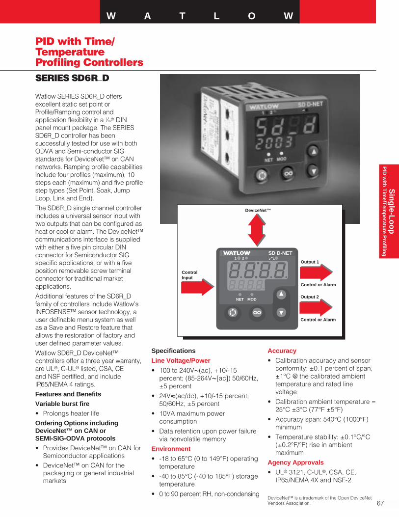
W A T L O W
67
Sin
gle-L
oo
pP
ID w
ith T
ime/T
emp
erature P
rofilin
g
SERIES SD6R_D
PID with Time/TemperatureProfiling Controllers
Specifications
Line Voltage/Power
• 100 to 240VÅ(ac), +10/-15percent; (85-264VÅ[ac]) 50/60Hz,±5 percent
• 24Vı(ac/dc), +10/-15 percent;50/60Hz, ±5 percent
• 10VA maximum powerconsumption
• Data retention upon power failurevia nonvolatile memory
Environment
• -18 to 65°C (0 to 149°F) operatingtemperature
• -40 to 85°C (-40 to 185°F) storagetemperature
• 0 to 90 percent RH, non-condensing
Accuracy
• Calibration accuracy and sensorconformity: ±0.1 percent of span,±1°C @ the calibrated ambienttemperature and rated linevoltage
• Calibration ambient temperature =25°C ±3°C (77°F ±5°F)
• Accuracy span: 540°C (1000°F)minimum
• Temperature stability: ±0.1°C/°C(±0.2°F/°F) rise in ambientmaximum
Agency Approvals
• UL® 3121, C-UL®‚ CSA, CE,IP65/NEMA 4X and NSF-2
Watlow SERIES SD6R_D offersexcellent static set point orProfile/Ramping control andapplication flexibility in a 1⁄16th DINpanel mount package. The SERIESSD6R_D controller has beensuccessfully tested for use with bothODVA and Semi-conductor SIGstandards for DeviceNet™ on CANnetworks. Ramping profile capabilitiesinclude four profiles (maximum), 10steps each (maximum) and five profilestep types (Set Point, Soak, JumpLoop, Link and End).
The SD6R_D single channel controllerincludes a universal sensor input withtwo outputs that can be configured asheat or cool or alarm. The DeviceNet™communications interface is suppliedwith either a five pin circular DINconnector for Semiconductor SIGspecific applications, or with a fiveposition removable screw terminalconnector for traditional marketapplications.
Additional features of the SD6R_Dfamily of controllers include Watlow’sINFOSENSE™ sensor technology, auser definable menu system as wellas a Save and Restore feature thatallows the restoration of factory anduser defined parameter values.
Watlow SD6R_D DeviceNet™controllers offer a three year warranty,are UL®, C-UL® listed, CSA, CE and NSF certified, and includeIP65/NEMA 4 ratings.
Features and BenefitsVariable burst fire• Prolongs heater lifeOrdering Options includingDeviceNet™ on CAN or SEMI-SIG-ODVA protocols• Provides DeviceNet™ on CAN for
Semiconductor applications• DeviceNet™ on CAN for the
packaging or general industrialmarkets
DeviceNet™ is a trademark of the Open DeviceNetVendors Association.
SDSD2 31
SDSD%21
NET MOD
21
NET MOD
21
NET MOD
SD D-NET
DeviceNet™
ControlInput
Output 1
Control or Alarm
Output 2
Control or Alarm
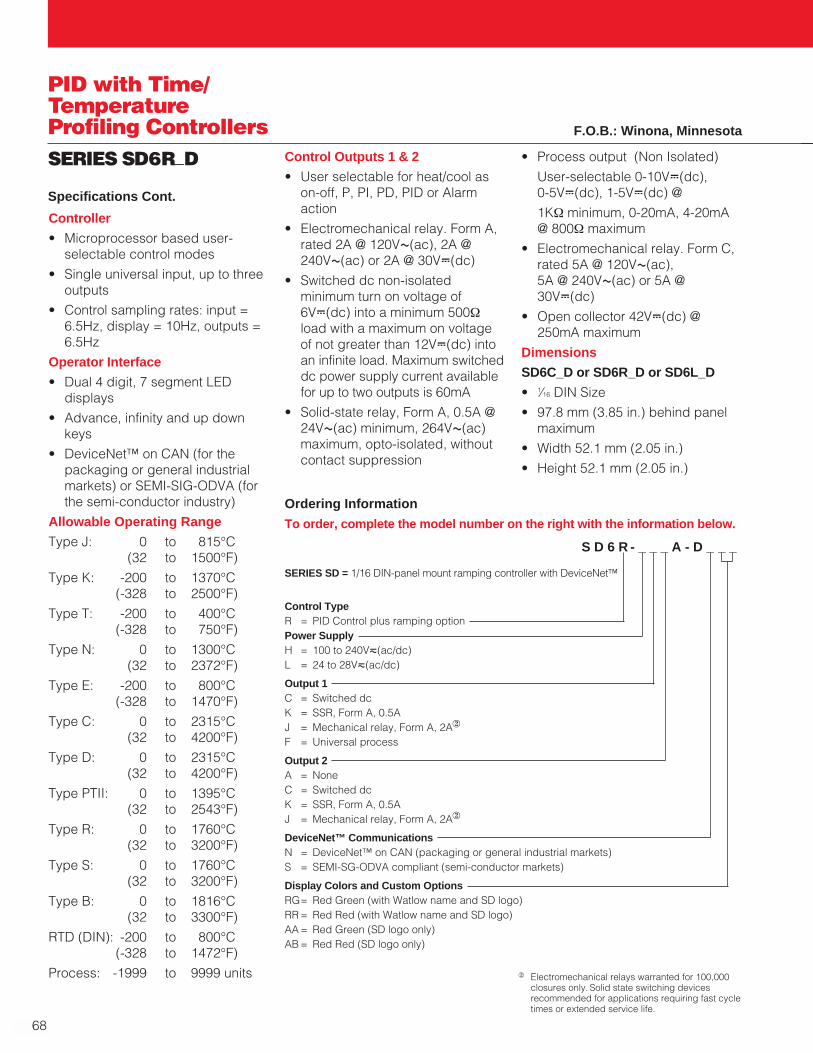
Ordering Information
To order, complete the model number on the right with the information below.
S D 6 R - _ _ _ A - D _ _ _
SERIES SD = 1/16 DIN-panel mount ramping controller with DeviceNet™
Control TypeR = PID Control plus ramping optionPower SupplyH = 100 to 240Vı(ac/dc)L = 24 to 28Vı(ac/dc)
Output 1C = Switched dcK = SSR, Form A, 0.5AJ = Mechanical relay, Form A, 2A2
F = Universal process
Output 2A = NoneC = Switched dcK = SSR, Form A, 0.5AJ = Mechanical relay, Form A, 2A2
DeviceNet™ CommunicationsN = DeviceNet™ on CAN (packaging or general industrial markets)S = SEMI-SG-ODVA compliant (semi-conductor markets)
Display Colors and Custom OptionsRG= Red Green (with Watlow name and SD logo)RR = Red Red (with Watlow name and SD logo)AA = Red Green (SD logo only)AB = Red Red (SD logo only)
68
PID with Time/TemperatureProfiling ControllersSERIES SD6R_D
Controller
• Microprocessor based user-selectable control modes
• Single universal input, up to threeoutputs
• Control sampling rates: input =6.5Hz, display = 10Hz, outputs =6.5Hz
Operator Interface
• Dual 4 digit, 7 segment LEDdisplays
• Advance, infinity and up downkeys
• DeviceNet™ on CAN (for thepackaging or general industrialmarkets) or SEMI-SIG-ODVA (forthe semi-conductor industry)
Allowable Operating Range
Type J: 0 to 815°C(32 to 1500°F)
Type K: -200 to 1370°C(-328 to 2500°F)
Type T: -200 to 400°C(-328 to 750°F)
Type N: 0 to 1300°C(32 to 2372°F)
Type E: -200 to 800°C(-328 to 1470°F)
Type C: 0 to 2315°C(32 to 4200°F)
Type D: 0 to 2315°C(32 to 4200°F)
Type PTII: 0 to 1395°C(32 to 2543°F)
Type R: 0 to 1760°C(32 to 3200°F)
Type S: 0 to 1760°C(32 to 3200°F)
Type B: 0 to 1816°C(32 to 3300°F)
RTD (DIN): -200 to 800°C(-328 to 1472°F)
Process: -1999 to 9999 units
Specifications Cont.
Control Outputs 1 & 2
• User selectable for heat/cool ason-off, P, PI, PD, PID or Alarmaction
• Electromechanical relay. Form A,rated 2A @ 120VÅ(ac), 2A @240VÅ(ac) or 2A @ 30VÎ(dc)
• Switched dc non-isolatedminimum turn on voltage of6VÎ(dc) into a minimum 500Ωload with a maximum on voltageof not greater than 12VÎ(dc) intoan infinite load. Maximum switcheddc power supply current availablefor up to two outputs is 60mA
• Solid-state relay, Form A, 0.5A @24VÅ(ac) minimum, 264VÅ(ac)maximum, opto-isolated, withoutcontact suppression
• Process output (Non Isolated)
User-selectable 0-10VÎ(dc), 0-5VÎ(dc), 1-5VÎ(dc) @
1KΩ minimum, 0-20mA, 4-20mA@ 800Ω maximum
• Electromechanical relay. Form C,rated 5A @ 120VÅ(ac), 5A @ 240VÅ(ac) or 5A @30VÎ(dc)
• Open collector 42VÎ(dc) @250mA maximum
Dimensions
SD6C_D or SD6R_D or SD6L_D
• 1⁄16 DIN Size
• 97.8 mm (3.85 in.) behind panelmaximum
• Width 52.1 mm (2.05 in.)
• Height 52.1 mm (2.05 in.)
F.O.B.: Winona, Minnesota
2 Electromechanical relays warranted for 100,000closures only. Solid state switching devicesrecommended for applications requiring fast cycletimes or extended service life.
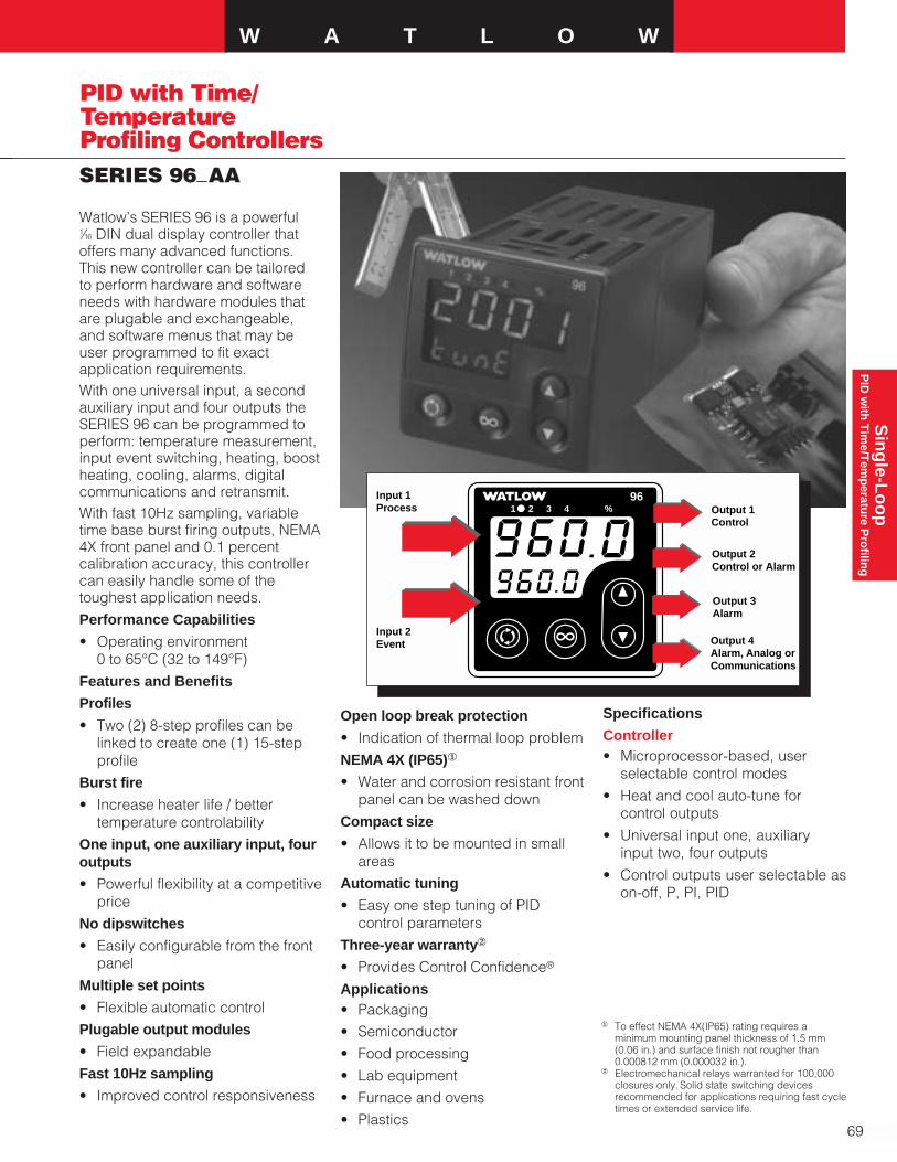
W A T L O W
69
Sin
gle-L
oo
pP
ID w
ith T
ime/T
emp
erature P
rofilin
g
SERIES 96_AA
Watlow’s SERIES 96 is a powerful 1⁄16 DIN dual display controller thatoffers many advanced functions.This new controller can be tailored to perform hardware and softwareneeds with hardware modules thatare plugable and exchangeable,and software menus that may beuser programmed to fit exactapplication requirements.With one universal input, a secondauxiliary input and four outputs theSERIES 96 can be programmed toperform: temperature measurement,input event switching, heating, boostheating, cooling, alarms, digitalcommunications and retransmit.With fast 10Hz sampling, variabletime base burst firing outputs, NEMA4X front panel and 0.1 percentcalibration accuracy, this controllercan easily handle some of thetoughest application needs.
Performance Capabilities
• Operating environment 0 to 65°C (32 to 149°F)
Features and Benefits
Profiles
• Two (2) 8-step profiles can belinked to create one (1) 15-stepprofile
Burst fire
• Increase heater life / bettertemperature controlability
One input, one auxiliary input, fouroutputs
• Powerful flexibility at a competitiveprice
No dipswitches
• Easily configurable from the frontpanel
Multiple set points
• Flexible automatic control
Plugable output modules
• Field expandable
Fast 10Hz sampling
• Improved control responsiveness
Open loop break protection
• Indication of thermal loop problem
NEMA 4X (IP65)1
• Water and corrosion resistant frontpanel can be washed down
Compact size
• Allows it to be mounted in smallareas
Automatic tuning
• Easy one step tuning of PIDcontrol parameters
Three-year warranty2
• Provides Control Confidence®
Applications• Packaging
• Semiconductor
• Food processing
• Lab equipment
• Furnace and ovens
• Plastics
1 To effect NEMA 4X(IP65) rating requires aminimum mounting panel thickness of 1.5 mm(0.06 in.) and surface finish not rougher than0.000812 mm (0.000032 in.).
2 Electromechanical relays warranted for 100,000closures only. Solid state switching devicesrecommended for applications requiring fast cycletimes or extended service life.
2 3 4 %96
1Input 1Process
Input 2Event
Output 1Control
Output 2Control or Alarm
Output 3Alarm
Output 4Alarm, Analog or Communications
Specifications
Controller• Microprocessor-based, user
selectable control modes
• Heat and cool auto-tune for control outputs
• Universal input one, auxiliaryinput two, four outputs
• Control outputs user selectable ason-off, P, PI, PID
PID with Time/TemperatureProfiling Controllers
70
SERIES 96_AA
• Input sample period; Single input10Hz (100ms), dual input 5Hz(200ms) digital filter adjustable
• Display update; 2Hz (500ms),time filter adjustable
• Output update; burst, 0.1 to 999.9seconds
• Input /Output/Communicationisolation
• Displayed in °C, °F or processunits
Operator Interface• Dual four-digit LED displays:
upper 10.2 mm (0.4 in.), lower 6.2 mm (0.244 in.)
• Advance, Up Arrow, Down Arrow,Infinity tactile keys
Standard Conditions ForSpecifications• Ambient temperature 25°C (77°F)
±3°C, rated line voltage, 50 to60Hz, 0 to 90 percent RH non-condensing, 15 minute warm-up
Universal Input 1Thermocouple• Type J, K, T, N, C (W5), E, Pt 2, D
(W3), B, R, S thermocouple
• >20MΩ input impedance
• Maximum 20Ω source resistance
• 30µA open detection bias
RTD• 2- or 3-wire platinum, 100Ω
• JIS and DIN-curves
• Whole or tenth degree indication
• 150µA nominal RTD excitationcurrent
Process• Range selectable: 0-10VÎ(dc),
0-5VÎ(dc), 1-5VÎ(dc), 0-20mA,4-20mA
• Voltage input impedance 20kΩ
• Current input impedance 100Ω
• Minimum current sourceresistance 1MΩ
• Input resolution 50,000 bits(approx.) at full scale
• mV input impedance 20MΩ
Input 2Event Input• Contact or voltage
• 20KΩ input impedance
• Voltage input: event high state 3 to 36VÎ(dc), event low state 0 to 2VÎ(dc)
• Resistance/contact input: eventhigh state >23kΩ, event low state0 to 2kΩ
Output TypesOpen Collector/Switched DC• Open collector configuration:
Maximum voltage 42VÎ(dc)Maximum current 200mA Maximum on resistance 1.1ΩMaximum off state leakagecurrent 100µA
• Switched dc configuration:Switched dc supply voltage 22 to 28VÎ(dc) dc supply currentlimited to 30mA
Solid State Relay• Optically isolated
• Zero cross switched
• Without contact suppression
• Minimum load current 0.5mA rms
• Maximum current 0.5A rms at 20 to 280VÅ(ac)
• Maximum off state leakagecurrent 10µA rms
• For resistive loads only, must useRC suppression for inductiveloads
Electromechanical Relay• Form C contact configuration
• Minimum load current 10mA @5VÎ(dc)
• Rated resistive and inductiveloads: 2A @ 250VÅ(ac) or30VÎ(dc) maximum
• Electrical life 100,000 cycles atrated current
• For resistive loads only, must useRC suppression for inductiveloads
Process• Range selectable: 0-20mA,
4-20mA, 0-5VÎ(dc), 1-5VÎ(dc),0-10VÎ(dc)
• Reverse or direct acting
• 0 to 10VÎ(dc) voltage output into1000Ω minimum load resistance
• 0 to 20mA current output into800Ω maximum load resistance
• Resolution:VÎ(dc) ranges = 2.5mV nominalmA ranges = 5µA nominal
• Calibration accuracy:VÎ(dc) ranges = ±15mVmA ranges = ±30µA
• Temperature stability 100ppm/°C
Retransmit
• Range selectable: 0-20mA, 4-20mA, 0-5VÎ(dc), 1-5VÎ(dc),0-10VÎ(dc)
• 0 to 10VÎ(dc) voltage output intoa 1,000Ω minimum loadresistance
• 0 to 20mA current output into an800Ω maximum load resistance
• Resolution: VÎ(dc) ranges = 2.5mV nominalmA ranges = 5µA nominal
• Calibration accuracy:VÎ(dc) ranges = ±15mVmA ranges = ±30µA
• Temperature stability 100ppm/°C
Communications
• EIA/TIA-485, EIA/TIA-232
• Opto-isolated
• Modbus™ RTU protocol
• 1200, 2400, 4800, 9600, 19200baud rates
• 32 maximum units can beconnected (With additional 485repeater hardware, up to 247units may be connected)
PID with Time/TemperatureProfiling Controllers
Specifications Cont.

W A T L O W
71
Sin
gle-L
oo
pP
ID w
ith T
ime/T
emp
erature P
rofilin
g
SERIES 96_AA
Accuracy
Input ranges
Type J 0 to 750°C(32 to 1382°F)
Type K -200 to 1250°C(-328 to 2282°F)
Type T -200 to 1250°C(-328 to 2282°F
Type N 0 to 1250°C(32 to 2282°F)
Type E -200 to 900°C(-328 to 1652°F)
Type C(W5) 0 to 2315°C(32 to 4200°F)
Type D(W3) 0 to 2315°C(32 to 4200°F)
Pt 2 0 to 1393°C(32 to 2540°F)
Type R 0 to 1450°C(32 to 2642°F)
Type S 0 to 1450°C(32 to 2642°F)
Type B 870 to 1700°C(1598 to 3092°F)
DIN -200 to 800°C(-328 to 1472°F)
JIS -200 to 630°C(-328 to 1166°F)
Process -1999 to 9999 units
Thermocouple Inputs
• Calibration accuracy ±0.1 percentof span ±1°C at standardconditions
Exceptions: Type T: 0.12 percent of span for -200°C to -50°C (-328°F to -58°F)
Types R and S: 0.15 percent ofspan for 0°C to 100°C (32°F to2120°F)
Type B: 0.24 percent of span for870°C to 1700°C (1598°F to3092°F)
• Accuracy span: 540°C (1000°F)minimum
• Temperature stability: ±0.1degree per degree change inambient
RTD Inputs• Calibration accuracy ±0.1 percent
of span ±1°C at standardconditions
• Accuracy span: 540°C (1000°F)minimum
• Temperature stability: ±0.05degree per degree change inambient
Process Inputs• Voltage input ranges
Accuracy ±15mV ±1 LSD atstandard conditions
Temperature stability±100ppm/°C maximum
• Milli-amp input ranges
Accuracy ±30µA ±1 LSD atstandard conditions
Temperature stability±100ppm/°C maximum
Agency Approvals
• UL® 916, File #E185611, C-UL®,CE, NEMA 4X
Terminals
• Touch safe
• 22 to 12 AWG
Power
• 100-240VÅ(ac) +10 percent, -15 percent; 50/60Hz, ±5 percent
• 24-28VÅ(ac) or VÎ(dc) +10percent, -15 percent; 50/60Hz, ±5 percent
• 7.0VA maximum powerconsumption
• Data retention upon power failurevia nonvolatile memory
Operating Environment
• 0 to 65°C (32 to 149°F)
• 0 to 90 percent RH, non-condensing
• Storage temperature: -40 to 85°C(-40 to 185°F)
Controller Weight (approx.)
• 0.2 kg (0.4 lb)
Allowable Operating Ranges
Type J 1.0 0 to 815°C (32 to 1500°F)
0.1 0 to 815°C(32 to 1499°F)
Type K 1.0 -270 to 1370°C(-454 to 2498°F)
0.1 -199.9 to 999.9°C(-327.8 to 1831.8°F)
Type T 1.0 -270 to 400°C(-454 to 750°F)
0.1 -199.9 to 400°C(-327.8 to 750°F)
Type N 1.0 0 to 1300°C(32 to 2372°F)
0.1 0 to 999.9°C(32 to 1831.8°F)
Type E 1.0 -270 to 800°C(-454 to 1470°F)
0.1 -199.9 to 800°C(-327.8 to 1472°F)
Type C 1.0 0 to 2315°C(32 to 4200°F)
0.1 0 to 999.9°C(32 to 1831.8°F)
Type D 1.0 0 to 2315°C(32 to 4200°F)
0.1 0 to 999.9°C(32 to 1831.8°F)
Pt 2 1.0 0 to 1395°C(32 to 2543°F)
0.1 0 to 999.9°C(32 to 999.9°F)
Type R 1.0 0 to 1760°C(32 to 3200°F)
Type S 1.0 0 to 1760°C(32 to 3200°F)
Type B 1.0 0 to 1816°C(32 to 3300°F)
DIN 1.0 -200 to 800°C(-328 to 1472°F)
0.1 -199.9 to 800°C(-327.8 to 1472°F)
JIS 1.0 -200 to 630°C(-328 to 1166°F)
0.1 -199.9 to 630.0°C(-327.8 to 1166°F)
Process -1999 to 9999 units
PID with Time/TemperatureProfiling Controllers

72
SERIES 96_AA
Input 1
Input 2
Output 1
Output 2
Output 3
Output 4
Dimensions
OverallHeight: 52 mm (2.05 in.)
Width: 52 mm (2.05 in.)
Length: 107 mm (4.2 in.)
Depth behind panel surface98.4 mm (3.875 in.)
Ordering InformationTo order, complete the code number on the right with the information below:
9 6 _ _ - _ _ _ _ - _ _ _ _SERIES 96 = Microprocessor-based 1⁄16 DIN, with universalinput 1. Options include: software, power supply, input 2, outputs and display color.
Power Supply
A = 100-240Vı(ac/dc)B = 24-28Vı(ac/dc)Input 2
0 = None1 = Event input and 0-5VÎ(dc)/4-20mA (Remote set point input)Output 1
C = Switched dc/open collectorD = Electromechanical relay, Form C, 2A, without RC suppression2
F = Universal Process, range selectable: 0-20mA, 4-20mA,0-5VÎ(dc), 1-5VÎ(dc), 0-10VÎ(dc)
K = 0.5A solid state relay without RC suppressionOutput 2
A = NoneC = Switched dc/open collectorD = Electromechanical relay, Form C, 2A, without RC suppression2
F = Universal Process, range selectable: 0-20mA, 4-20mA,0-5VÎ(dc), 1-5VÎ(dc), 0-10VÎ(dc)
K = 0.5A solid state relay without RC suppressionOutput 3
A = NoneD = Electromechanical relay, Form C, 2A, without RC suppression2
Output 4
A = NoneD = Electromechanical relay, Form C, 2A, without RC suppression2
R = 232 CommunicationsU = 485 CommunicationsM = Universal Retransmit, range selectable: 0-20mA, 4-20mA,
0-5VÎ(dc), 1-5VÎ(dc), 0-10VÎ(dc)Software/Preset Parameters
AA = Ramping softwareDisplay/Overlay
Upper/Lower Upper/LowerRR = Red/Red display GR = Green/Red displayRG = Red/Green display GG = Green/Green display
2 3 4 %96
1
52.070 mm(2.050 in.)
52.070 mm(2.050 in.)
Panel Cutout44.958 mm x 44.958 mm
(1.77 in. x 1.77 in.)
107.747 mm(4.242 in.)
9.322 mm(0.367 in.)
98.425 mm(3.875 in.)
59.182 mm(2.330 in.)
Functionality Matrix
Univ
ersa
lIn
put
Even
t &Re
mot
eSe
t Poi
nt
Cont
rol
Alar
m
Retra
nsm
it
232
485
Com
m
PID with Time/TemperatureProfiling Controllers F.O.B.: Winona, Minnesota
2 Electromechanical relays warranted for 100,000closures only. Solid state switching devicesrecommended for applications requiring fast cycletimes or extended service life.

W A T L O W
73
Sin
gle-L
oo
pP
ID w
ith T
ime/T
emp
erature P
rofilin
g
SERIES 981/982
The Watlow SERIES 981 (horizontal)and SERIES 982 (vertical) are 1⁄8 DINtime/temperature profile controllers.Among the most easy-to-usetime/temperature profile controllers,they are designed with most typicalprogramming needs in mind. Bothvertical and horizontal models offerfour-file/24-step program capabilityor easy-to-use fixed set pointoperation.Time/temperature profile operationincludes four files with six steps ineach file. Programming optionsinclude ramp-rate or time-basedprofiles, guaranteed soak deviation,program looping and program statusselection after power outage. Thefiles may be linked to create a single24-step program.The primary analog input accepts 11 different thermocouple types,RTD or scalable process inputs. Asecond analog input can be factoryconfigured for a slidewire feedbackinput, common in gas valve control.With up to two event inputs, theSERIES 981/982 offers remoteprogram start or hold capability andallows the operator to program await-for event.Performance Capabilities• Exceptional accuracy to
±0.1 percent of span• Operating environment
0 to 55°C (32 to 130°F)Features and BenefitsFour files/six steps per file• Meets the need of most time/
temperature profile applications(files may be linked together)
Auto-tuning of both heat and cooloutputs• Provide easy operation with one-
step tuning of system parametersOptional dual auxiliary outputs• Give flexibility to time-based
events or alarm outputs
Optional retransmit of set point orprocess variable• For master programmer or chart
recorder connectionHardware and software parameterlockout options • Provide several levels of operator
securityUL®, CE, NEMA 4X1 (IP65) front panel • Provides corrosion resistance10Hz sampling rate and burst-fire control • Delivers smooth, accurate
process control
Slidewire feedback • Interfaces with most slidewire
input positioning devicesThree-year warranty2
• Provides Control Confidence®
Applications• Any process requiring
time/temperature profile control• Processes requiring slidewire
control of valves or positions
TL WWA
PROCESS
L1 L2 L3 L4
DEV
% OUTDISPLAY
SERIES 982
MODE
HOLDRUN
Input 1Type B, C, D, E, J, K, N, R, S, T or Pt 2Thermocouple, DIN/JIS RTD orProcess
Input 3Digital Event
Input 2Slidewire orDigital Event
Output 1PID, on-off Control
Output 2PID, on-off ControlAlarmTransmitter Power Supply
Output 3AlarmTransmitter Power SupplyAnalog RetransmitEvent
Output 4AlarmTransmitter Power SupplyEventSerial Communications
Auto-tuneHeat/Cool
Process Deviation from Set Point
1 To effect NEMA 4X (IP65) rating requires aminimum mounting panel thickness of 1.5 mm(0.06 in.) and surface finish not rougher than0.000812 mm (0.000032 in.).
2 Electromechanical relays warranted for 100,000closures only. Solid state switching devicesrecommended for applications requiring fast cycle times or extended service life.
PID with Time/TemperatureProfiling Controllers

74
SERIES 981/982
• Complex process furnaces• Environmental chambers• Processes needing data loggingSpecifications
Control Mode• Single input, quad output,
optional retransmit of set point orprocess variable
• Programmable direct and reverse acting control outputs
• 4-file/6 steps per file time/temperature profile or fixed setpoint control
• Ramp-rate or time-basedprogramming
• Selectable control status followingpower loss
Agency Approvals• 89/336/EEC Electromagnetic
Compatibility Directive• EN 50081-2: 1994 Emissions• EN 50082-2: 1994 Immunity• 73/23/EEC Low Voltage Directive• EN 601010-1: 1993 Safety• UL® #873, C-UL® File #43684• NEMA 4X
Operator Interface• Dual, four digit LED displays.
Upper: 10 mm (0.4 in.) Lower: 8 mm (0.3 in.)
• MODE, HOLD/RUN, DISPLAY, UP and DOWN keys
Accuracy• Calibration accuracy and sensor
conformity: ±0.1 percent of span,±1 LSD, 25°C ±3°C (77°F ±5°F)ambient and rated line voltage±10 percent
• Accuracy span: 540°C (1000°F)minimum
• Temperature stability: 0.1°C/°C (± 0.2°F/°F) change in ambient
Sensors/Inputs• Contact input for software function
select (event input)
• Thermocouple Types B, C1, D1,E, J, K, N, R, S, T and Pt 21
• RTD resolution in 1° or 0.1°RTD scales
• Process variables: 0-50mVÎ(dc), 0-20mAÎ(dc), 4-20mAÎ(dc), 0-5VÎ(dc), 1-5VÎ(dc), 0-10VÎ(dc)
• Slidewire or digital event inputoptions
• Sensor break protection de-energizes system for safety.Latching or non-latching
Input RangeSpecified temperature rangesrepresent the controller's operationalspan.
ThermocoupleAvailable with basic or universal signal conditionerType C1 0 to 2316°C
(32 to 4200°F)Type D1 0 to 2316°C
(32 to 4200°F)Type E -200 to 799°C
(-328 to 1470°F)Type J 0 to 816°C
(32 to 1500°F)Type K -200 to 1371°C
(-328 to 2500°F)Type N 0 to 1300°C
(32 to 2372°F)Type T -200 to 399°C
(-328 to 750°F)Pt 21 0 to 1395°C
(32 to 2543°F)Available with universal signalconditionerType B 870 to 1816°C
(1598 to 3300°F)Type R 0 to 1760°C
(32 to 3200°F)Type S 0 to 1760°C
(32 to 3200°F)
RTD Resolution (DIN or JIS)1° (DIN) -200 to 800°C
(-328 to 1472°F)1° (JIS) -200 to 630°C
(-328 to 1166°F)0.1° (DIN and JIS)
-73.3 to 537.7°C(-99.9 to 999.9°F)
Process0-5VÎ(dc) 1-5VÎ(dc)0-10VÎ(dc) 0-20mAÎ(dc)4-20mAÎ(dc) 0-50mVÎ(dc)
-999 to 9999 units#2 input slidewire feedback
100 to 1200ΩOutput Options• Solid state relay, Form A, 0.5A @
24VÅ(ac) min., 253VÅ(ac) max.,opto-isolated, burst fire switching.With or without contactsuppression. Off state outputimpedance is 20kΩ with RCsuppression, 31MΩ withoutcontact suppression
• Open collector or switched dcsignal provides a minimum turn onvoltage of 3VÎ(dc) into aminimum 500Ω load; maximum onvoltage not greater than 32VÎ(dc)into an infinite load, isolated
• Electromechanical relay2, Form C, 5A @ 120/240VÅ(ac), 6A@ 28VÎ(dc), 1⁄8 hp. @ 120VÅ(ac),125VA @ 120VÅ(ac). With orwithout contact suppression. Offstate output impedance with RCsuppression is 20kΩ
• Process, 0-20mAÎ(dc), 4-20mAÎ(dc) into 800Ωmaximum, 0-5VÎ(dc), 1-5VÎ(dc),or 0-10VÎ(dc) into 1kΩ minimumreverse acting, isolated
• Electromechanical relay2, Form A/B, 5A @ 120/240VÅ(ac), 6A @ 28VÎ(dc), 1⁄8 hp. @120VÅ(ac), 125VA @ 120VÅ(ac).Without contact suppression
1 Not an ANSI Symbol.2 Electromechanical relays warranted for 100,000
closures only. Solid state switching devicesrecommended for applications requiring fast cycletimes or extended service life.
Applications Cont.
PID with Time/TemperatureProfiling Controllers

W A T L O W
75
Sin
gle-L
oo
pP
ID w
ith T
ime/T
emp
erature P
rofilin
g
SERIES 981/982
Availability
Four working days for orders lessthan 20 units. For orders over 20units, consult factory for release andshipment schedules.
Slo-Blo® is a registered trademark ofLittelfuse, Inc.Quencharc® is a registered trademark of ITWPaktron.
• External transmitter power supply,5, 12 or 20VÎ(dc) @ 30mA
• EIA/TIA-232 communications orEIA/TIA-485/EIA/TIA-422communications, opto-isolated
• Retransmit: 0-20mAÎ(dc), 4-20mAÎ(dc) with 600Ω max.load impedance, or 0-5VÎ(dc), 1-5VÎ(dc) and 0-10VÎ(dc) with500Ω min. load impedance
Line Voltage/Power• 100-240Vı(ac/dc) +10 percent,
-15 percent; 50/60Hz, ±5 percent• 24 to 28Vı(ac/dc) +10 percent,
-15 percent; 50/60Hz, ±5 percent• Fused internally (factory replace-
able only) Slo-Blo® type (time-lag)2A, 250V for high voltage versions5A, 250V for low voltage versions
• Power consumption 16VA maximum
• Data retention upon power failurevia non-volatile memory
Operating Environment• 0 to 55°C (32 to 130°F)• 0 to 90 percent RH, non-condensing
Ordering Information
To order, complete the code number with the information below:SERIES 981/982 = Ramping controller 9 8 _ C - _ _ _ _ - _ _ _ _1 analog input, 4 outputs, 2 digital inputs
Power Supply & Mounting1 = 100 to 240Vı(ac/dc) nominal, horizontal mounting2 = 100 to 240Vı(ac/dc) nominal, vertical mounting3 = 24 to 28Vı(ac/dc) nominal, horizontal mounting4 = 24 to 28Vı(ac/dc) nominal, vertical mounting
SoftwareC = Standard (4-file/6 step per file program capability)S = Special customer feature
Input 11 = Basic thermocouple signal conditioner
(excluding Type B, R and S)2 = Universal signal conditioner (see Range Information)
Input 20 = None3 = Slidewire feedback (see Range Information)5 = Second digital event (one digital event is standard on all units)
Output 1b
B = Solid state relay, Form A, 0.5A, with RC suppressionC = Switched dc or open collector, isolatedD = Electromechanical relaya, Form C, 5A with RC suppressionE = Electromechanical relaya, Form C, 5A without contact suppressionF = Universal process, 0-5VÎ(dc), 1-5VÎ(dc), 0-10VÎ(dc),
0-20mAÎ(dc), 4-20mAÎ(dc), isolatedK = Solid state relay, Form A, 0.5A, without contact suppression
Output 2b
A = NoneB = Solid state relay, Form A, 0.5A, with RC suppressionC = Switched dc or open collector, isolatedD = Electromechanical relaya, Form C, 5A with RC suppressionE = Electromechanical relaya, Form C, 5A without contact suppressionF = Universal process 0-5VÎ(dc), 1-5VÎ(dc), 0-10VÎ(dc),
0-20mAÎ(dc), 4-20mAÎ(dc), isolatedK = Solid state relay, Form A, 0.5A, without contact suppressionT = External signal conditioner power supply, 5, 12 or 20VÎ(dc) @ 30mA
Output 3c
A = NoneB = Solid state relay, Form A, 0.5A, with RC suppressionC = Switched dc or open collector, isolatedJ = Electromechanical relaya, Form A or B, 5A without contact suppressionK = Solid state relay, Form A, 0.5A without contact suppressionM = Retransmit, 0-20mAÎ(dc), 4-20mAÎ(dc)N = Retransmit, 0-5VÎ(dc), 1-5VÎ(dc), 0-10VÎ(dc)T = External signal conditioner power supply, 5, 12 or 20VÎ(dc) @ 30mA
Output 4c
A = NoneB = Solid state relay, Form A, 0.5A, with RC suppressionC = Switched dc or open collector, isolatedD = Electromechanical relaya, Form C, 5A with RC suppressionE = Electromechanical relaya, Form C, 5A without contact suppressionK = Solid state relay, Form A, 0.5A without contact suppressionR = EIA/TIA-232 communications, opto-isolatedS = EIA/TIA-485/EIA/TIA-422 communications, opto-isolatedU = EIA/TIA-232, EIA/TIA-485 software selectable, communications, opto-isolatedT = External signal conditioner power supply, 5, 12 or 20VÎ(dc) @ 30mA
Display Color (Upper/Lower)GG = Green/GreenGR = Green/RedXX = Custom overlays or default settings
RG = Red/GreenRR = Red/Red
Note: If this output will drive a solenoid, MDR,contactor or other inductive device, order aQuencharc® (0804-0147-0000) for output protection.See user’s manual for wiring.a Electromechanical relays warranted for 100,000
closures only. Solid state switching devicesrecommended for applications requiring fast cycletimes or extended service life.
b Output cannot be configured as an event output.c Event output capable.
PID with Time/TemperatureProfiling Controllers F.O.B.: Winona, Minnesota
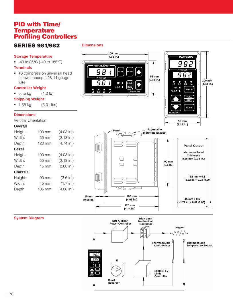
76
SERIES 981/982
Dimensions
Vertical Orientation
Overall
Height: 100 mm (4.03 in.)
Width: 55 mm (2.18 in.)
Depth: 120 mm (4.74 in.)
Bezel
Height: 100 mm (4.03 in.)
Width: 55 mm (2.18 in.)
Depth: 15 mm (0.68 in.)
Chassis
Height: 90 mm (3.6 in.)
Width: 45 mm (1.7 in.)
Depth: 105 mm (4.06 in.)
100 mm(4.03 in.)
55 mm(2.18 in.)
TL WWA
PROCESS
L1 L2 L3 L4
DEV
% OUT
MODE
SERIES 981
DSPY
HOLD
RUN
Panel Cutout
Maximum PanelThickness
9.65 mm (0.38 in.)
92 mm + 0.8(3.62 in. + 0.03 -0.00)
45 mm + 0.6(1.77 in. + 0.02 -0.00)
Panel AdjustableMounting Bracket
105 mm(4.06 in.)
15 mm(0.68 in.)
90 mm(3.6 in.)
120 mm(4.74 in.)
DIN-A-MITE®
Power Controller
High LimitMechanical Contactor
Heater
ThermocoupleLimit Sensor
ThermocoupleTemperature Sensor
SERIES LVLimit Controller
TL WWA
PROCESS
SERIES 982
ChartRecorder
System Diagram
100 mm(4.03 in.)
55 mm(2.18 in.)
TL WWA
PROCESS
L1 L2 L3 L4
DEV
% OUTDISPLAY
SERIES 982
MODE
HOLDRUN
Storage Temperature• -40 to 85°C (-40 to 185°F)Terminals• #6 compression universal head
screws, accepts 28-14 gaugewire
Controller Weight• 0.45 kg (1.0 lb)Shipping Weight• 1.35 kg (3.01 lbs)
Dimensions
PID with Time/TemperatureProfiling Controllers
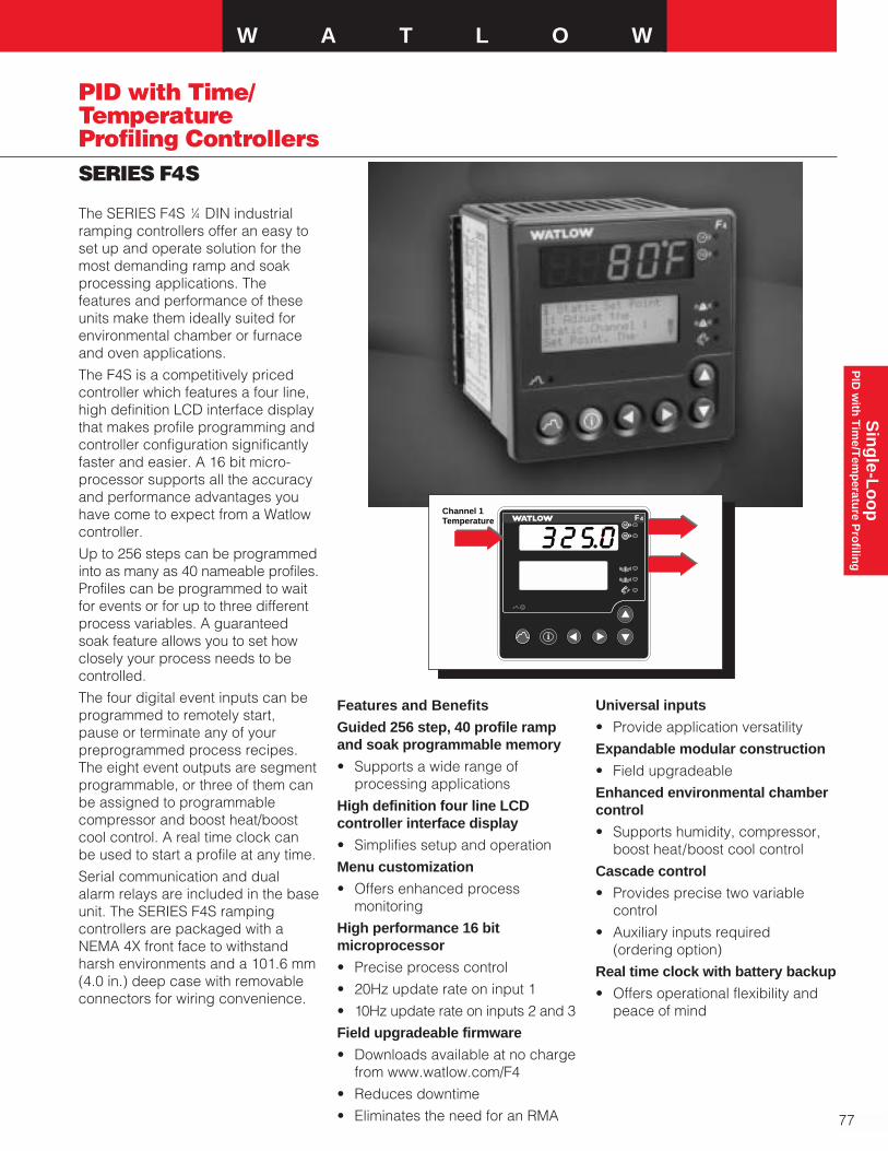
W A T L O W
77
Sin
gle-L
oo
pP
ID w
ith T
ime/T
emp
erature P
rofilin
g
SERIES F4S
PID with Time/TemperatureProfiling Controllers
The SERIES F4S 1⁄4 DIN industrialramping controllers offer an easy toset up and operate solution for themost demanding ramp and soakprocessing applications. Thefeatures and performance of theseunits make them ideally suited forenvironmental chamber or furnaceand oven applications.
The F4S is a competitively pricedcontroller which features a four line,high definition LCD interface displaythat makes profile programming andcontroller configuration significantlyfaster and easier. A 16 bit micro-processor supports all the accuracyand performance advantages youhave come to expect from a Watlowcontroller.
Up to 256 steps can be programmedinto as many as 40 nameable profiles.Profiles can be programmed to waitfor events or for up to three differentprocess variables. A guaranteedsoak feature allows you to set howclosely your process needs to becontrolled.
The four digital event inputs can beprogrammed to remotely start,pause or terminate any of yourpreprogrammed process recipes.The eight event outputs are segmentprogrammable, or three of them canbe assigned to programmablecompressor and boost heat/boostcool control. A real time clock canbe used to start a profile at any time.
Serial communication and dualalarm relays are included in the baseunit. The SERIES F4S rampingcontrollers are packaged with aNEMA 4X front face to withstandharsh environments and a 101.6 mm (4.0 in.) deep case with removableconnectors for wiring convenience.
F 4
1
2
i
1A
1B
Channel 1Temperature
Features and Benefits
Guided 256 step, 40 profile rampand soak programmable memory
• Supports a wide range ofprocessing applications
High definition four line LCDcontroller interface display
• Simplifies setup and operation
Menu customization
• Offers enhanced processmonitoring
High performance 16 bitmicroprocessor
• Precise process control
• 20Hz update rate on input 1
• 10Hz update rate on inputs 2 and 3
Field upgradeable firmware
• Downloads available at no charge from www.watlow.com/F4
• Reduces downtime
• Eliminates the need for an RMA
Universal inputs
• Provide application versatility
Expandable modular construction
• Field upgradeable
Enhanced environmental chambercontrol
• Supports humidity, compressor,boost heat/boost cool control
Cascade control
• Provides precise two variablecontrol
• Auxiliary inputs required (ordering option)
Real time clock with battery backup
• Offers operational flexibility andpeace of mind
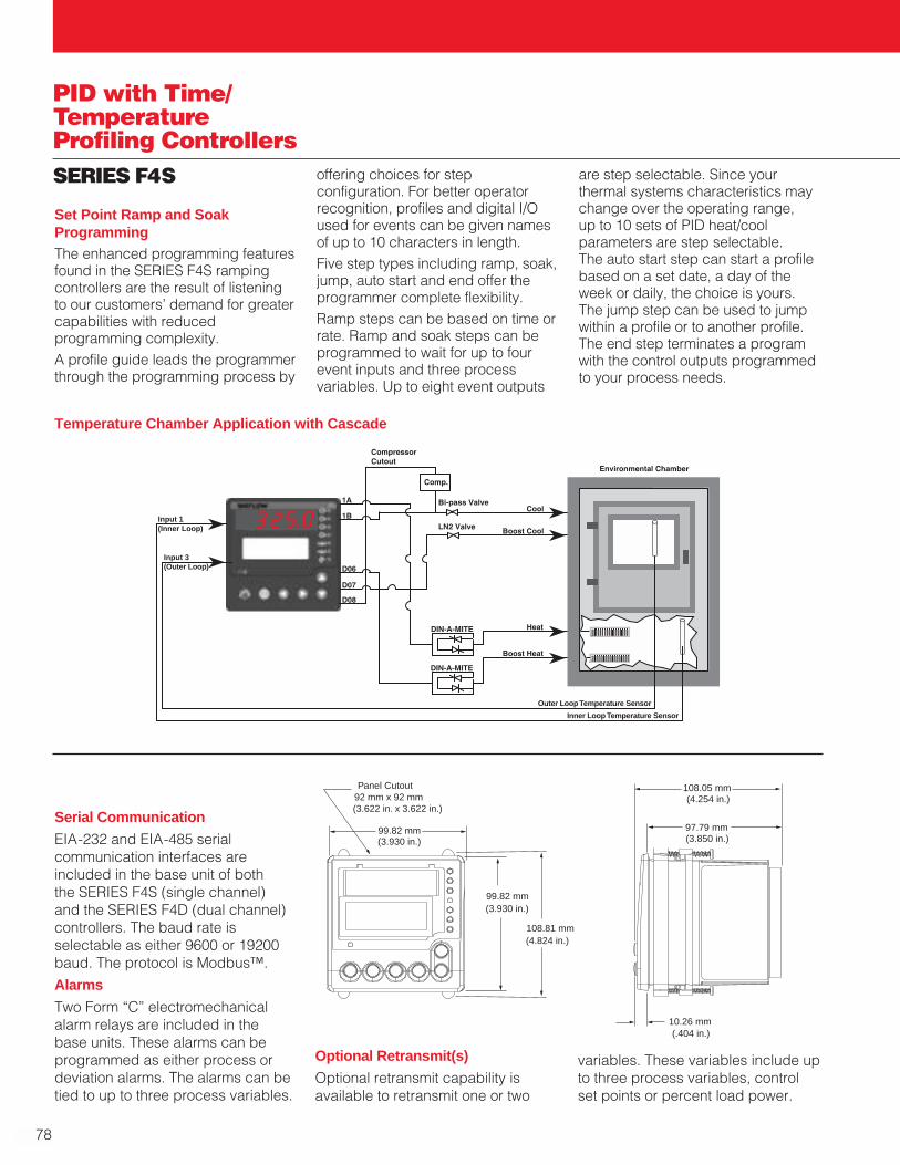
78
PID with Time/TemperatureProfiling ControllersSERIES F4S
Temperature Chamber Application with Cascade
99.82 mm
108.81 mm (4.824 in.)
(3.930 in.)
99.82 mm (3.930 in.)
(3.622 in. x 3.622 in.)
Panel Cutout92 mm x 92 mm
97.79 mm (3.850 in.)
108.05 mm(4.254 in.)
10.26 mm (.404 in.)
Set Point Ramp and SoakProgrammingThe enhanced programming featuresfound in the SERIES F4S rampingcontrollers are the result of listeningto our customers’ demand for greatercapabilities with reducedprogramming complexity.A profile guide leads the programmerthrough the programming process by
offering choices for stepconfiguration. For better operatorrecognition, profiles and digital I/Oused for events can be given namesof up to 10 characters in length.Five step types including ramp, soak,jump, auto start and end offer theprogrammer complete flexibility. Ramp steps can be based on time orrate. Ramp and soak steps can beprogrammed to wait for up to fourevent inputs and three processvariables. Up to eight event outputs
are step selectable. Since yourthermal systems characteristics maychange over the operating range, up to 10 sets of PID heat/coolparameters are step selectable. The auto start step can start a profilebased on a set date, a day of theweek or daily, the choice is yours.The jump step can be used to jumpwithin a profile or to another profile.The end step terminates a programwith the control outputs programmedto your process needs.
Serial Communication
EIA-232 and EIA-485 serialcommunication interfaces areincluded in the base unit of both the SERIES F4S (single channel) and the SERIES F4D (dual channel)controllers. The baud rate isselectable as either 9600 or 19200baud. The protocol is Modbus™.
Alarms
Two Form “C” electromechanicalalarm relays are included in the base units. These alarms can beprogrammed as either process ordeviation alarms. The alarms can betied to up to three process variables.
Input 1(Inner Loop)
Input 3(Outer Loop)
Outer Loop Temperature Sensor
Inner Loop Temperature Sensor
Optional Retransmit(s)
Optional retransmit capability isavailable to retransmit one or two
variables. These variables include upto three process variables, controlset points or percent load power.

W A T L O W
79
Sin
gle-L
oo
pP
ID w
ith T
ime/T
emp
erature P
rofilin
g
SERIES F4S
PID with Time/TemperatureProfiling Controllers
Specifications
Dimensions
• Width x height x depth99 mm x 99 mm x 97 mm panelmount (3.93 in. x 3.93 in. x 3.85 in.)
Universal Analog Inputs 1 (2 and 3 Optional)
• Updates rates, IN1 = 20Hz, IN2and IN3 = 10HZ
Thermocouple
• Type J, K, T, N, E, C (W5), D (W3),PTII, R, S, B
• Input impedance 20MΩ
RTD
• 2- or 3-wire platinum, 100, 500 or1000Ω
• JIS or DIN-curves, 1.0 or 0.1indication
Process
• Input resolution ≈50,000 bits at full scale
• Range selectable: 0-10VÎ(dc), 0-5VÎ(dc), 1-5VÎ(dc), 0-50mV, 0-20mA, 4-20mA
• Voltage input impedance 20KΩ
• Current input impedance 100Ω
Digital Inputs (4)
• Update rate = 10Hz
• Contact or dc voltage (36VÎ(dc)maximum)
• 10KΩ input impedance
Control Outputs (1A, 1B)
• Update rate = 20Hz
Open Collector/Switched dc
• Internal load switching (nominal):
Switched dc, 22 to 28VÎ(dc),limited @ 30mA
• External load switching(maximum):
Open collector 42VÎ(dc) @ 0.5A
Solid State Relay
• Zero switched, optically coupled,0.5A @ 24VÅ(ac) minimum,253VÅ(ac) maximum
Process Outputs (Optional Retransmit)
• Update rate = 1Hz
• User selectable 0-10VÎ(dc), 0-5VÎ(dc), 1-5VÎ(dc) @ 1KΩ min.,0-20mA, 4-20mA @ 800Ω max.
• Resolution:dc ranges = 2.5mV nominalmA ranges = 5µA nominal
• Calibration accuracy:dc ranges = ±15mVmA ranges = ±30µA
• Temperature stability 100ppm/°C
Alarm Outputs
• Output update rate 1Hz
• Electromechanical relay, Form C,2A @ 30VÎ(dc) or 240VÅ(ac)maximum
Digital Outputs (8)
• Update rate = 10Hz
• Open collector output
• Off = 42VÎ(dc) max @ 10µA
• On = 0.2VÎ(dc) max @ 50mA sink
• Internal supply: 5VÎ(dc), @ 80mA
Communications
EIA-232 and EIA-485 serialcommunications with Modbus™RTU protocol
Safety and Agency Approvals
• UL®/C-UL® 916 listed, File # E185611, process controlequipment
• IP65 and NEMA 4X
• CE to EN 61010-1 and 631326
Terminals
• Touch-safe removable terminalblocks, accepts 12 to 22 gauge wire
Power
• 100-240VÅ(ac), -15 percent, +10 percent; 50/60Hz, ±5 percent
• 24-28Vı(ac/dc), -15 percent, +10 percent (order option)
• 39VA maximum powerconsumption
• Data retention upon power failurevia nonvolatile memory (sevenyears for battery backed ram)
• Sensor input isolation from inputto input to output to communi-cation circuitry is 500VÅ(ac)
Operating Environment
• 0 to 55°C (32 to 130°F)
• 0 to 90 percent RH, non-condensing
• Storage temperature: -40 to 70°C(-40 to 158°F)
Accuracy
• Calibration accuracy and sensorconformity: ±0.1 percent of span±1°C @ 25°C ±3°C (77°F ±5°F)ambient and rated line voltage±10 percent with the followingexceptions:
Type T: 0.12 percent of span for-200°C to -50°C (-328°F to -58°F)
Types R and S: 0.15 percent ofspan for 0°C to 100°C (32°F to212°F)
Type B: 0.24 percent of span for870°C to 1700°C (1598°F to3092°F)
• Accuracy span: Less than orequal to operating ranges, 540°C (1000°F) minimum
• Temperature stability: ±0.1°C/°C(±0.1°F/°F) rise in ambient forthermocouples
±0.05°C/°C (±0.05°F/°F) rise inambient for RTD sensors
Displays
• Process: Five, seven segment LED, red
• Control interface display: highdefinition LCD, green

80
PID with Time/TemperatureProfiling ControllersSERIES F4SSensor Operating Ranges:Type J: 0 to 815°C
(32 to 1500°F)Type K: -200 to 1370°C
(-328 to 2500°F)Type T: -200 to 400°C
(-328 to 750°F)Type N: 0 to 1300°C
(32 to 2372°F)Type E: -200 to 800°C
(-328 to 1472°F)Type C: (W5) 0 to 2315°C
(32 to 4200°F)Type D: (W3) 0 to 2400°C
(32 to 4352°F)Type PTII: 0 to 1395°C
(32 to 2543°F)Type R: 0 to 1760°C
(32 to 3200°F)Type S: 0 to 1760°C
(32 to 3200°F)Type B: 0 to 1816°C
(32 to 3300°F)RTD (DIN): -200 to 800°C
(-328 to 1472°F)RTD (JIS): -200 to 800°C
(-328 to 1472°F)Process:-19,999 to 30,000 unitsSensor Accuracy Ranges:Input rangesType J: 0 to 750°C
(32 to 1382°F)Type K: -200 to 1250°C
(-328 to 2282°F)Type T: -200 to 350°C
(-328 to 662°F)Type N: 0 to 1250°C
(32 to 2282°F)Type E: -200 to 800°C
(-328 to 1472°F)Type C(W5): 0 to 2315°C
(32 to 4200°F)Type D(W3): 0 to 2400°C
(32 to 4352°F)Type PTII: 0 to 1393°C
(32 to 2540°F)Type R: 0 to 1450°C
(32 to 2642°F)Type S: 0 to 1450°C
(32 to 2642°F)Type B: 870 to 1700°C
(1598 to 3092°F)RTD (DIN): -200 to 800°C
(-328 to 1472°F)RTD (JIS): -200 to 630°C
(-328 to 1166°F)Process:-19,999 to 30,000 units
Ordering InformationTo order, complete the code number on the right with the information below:
F4 S - A -
SERIES F4S = 1⁄4 DIN, single channel ramping controller
Single Channel Ramping Controller1 universal analog input, 4-digital inputs, 8-digital outputs, 2 alarms, EIA-232/485 comms
Power SupplyH = 100-240Vı(ac/dc)L = 24-28Vı(ac/dc)
Output 1AC = Open collector/switched dc F = Process, 0-5, 1-5, 0-10VÎ(dc), 0-20mA, 4-20mAK = Solid state Form A 0.5 amp relay
Output 1BA = NoneC = Open collector/switched dc F = Process, 0-5, 1-5, 0-10VÎ(dc), 0-20mA, 4-20mAK = Solid state Form A 0.5 amp relay
Auxiliary Input Module 0 = None6 = Dual universal inputs
Auxiliary Retransmit Module0 = None1 = Single retransmit output 0-5, 1-5, 0-10VÎ(dc), 0-20mA, 4-20mA2 = Dual retransmit outputs 0-5, 1-5, 0-10VÎ(dc), 0-20mA, 4-20mA
Language and RTD Options1 = English with 100Ω RTD2 = German with 100Ω RTD3 = French with 100Ω RTD4 = Spanish with 100Ω RTD5 = English with 500 and 1KΩ RTD6 = German with 500 and 1KΩ RTD7 = French with 500 and 1KΩ RTD8 = Spanish with 500 and 1KΩ RTD
Display and Custom OptionsRG = Standard display (Red/Green display only)XX = Custom options: software, setting parameters, overlay
F.O.B.: Winona, Minnesota

W A T L O W
81
Sin
gle-L
oo
pL
imits
/Alarm
s
SERIES LV
Limits /Alarms
Watlow’s family of microprocessor-based limit controllers provides aneconomical solution for applicationsrequiring temperature limit control.These limits are available in a broadrange of packaging options, allowingusers to select the best version fortheir individual application. The limitsare available with an operatorinterface and can be ordered in 1⁄8DIN-square panel mount or DIN-railmount design configurations.The LV limit family incorporates amicroprocessor design platform.This design provides significantimprovements in the performance,repeatability and accuracy offeredby Watlow’s current line of analoglimit controllers.The variable SERIES LV limitincludes an operator interface forviewing and selecting the set point.A red, four-character seven segmentLED displays the set point. The setpoint selection is made with acontinuous turn rotary encoder.Operating range temperature valuesare customer definable in theproduct configuration part number.The limit controllers are FMapproved with special UL® approvalfor the open board potted versions.Watlow’s limit controllers includeindustry leading service and supportand are backed by a three-yearwarranty.Applications• Food preparation• Industrial machinery• Packaging• Plastics processingFeatures and BenefitsAdjustable set points• Offer control flexibility Four character LED display• Improves set point selection
accuracy
Multiple mounting options• Minimize installation timeHigh or low limit with auto ormanual reset• Provides application flexibilityFahrenheit or Celsius operationwith indication• Offers application flexibilitySensor break protection• Provides positive system shutdownAgency approvals• Meet certification
requirements/complianceMicroprocessor based technology• Ensures accurate repeatable controlSpecificationsLimit Controller• Microprocessor based, limit
controller• Nominal switching hysteresis,
typically 1.7°C (3°F)• High or low limit, factory selectable• Latching output requires manual
reset upon over or undertemperature condition
• Manual or automatic reset onpower loss, factory selectable
• Internal front panel or externalcustomer supplied momentary reset switch
• Input filter time: 1 second
Operator Interface• Four digit, seven segment LED
displays, 7 mm (0.28 in.) high• °C or °F indicator LED • Alarm indicator LED • Continuous turn, velocity sensitive
rotary encoder for set pointadjustment
• Front panel SET/RESETStandard Conditions ForSpecifications• Rated line voltage, 50 to 60Hz,
0 to 90 percent RH non-condensing, 15-minute warm-up
• Calibration ambient range: 25°C(77°F) ±3°C
Sensor InputThermocouple• Grounded or ungrounded• Type E, J, K, T thermocouple• >10 MΩ input impedance• 250 nV input referenced error per
1Ω source resistanceRTD• 2-wire platinum, 100Ω• DIN-curve (0.00385 curve) • 125 µA nominal RTD excitation
current
UL® and C-UL® are registered trademarks ofUnderwriter’s Laboratories, Inc.
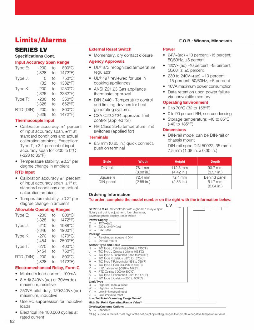
82
Limits /AlarmsSERIES LV
Input Accuracy Span RangeType E: -200 to 800°C
(-328 to 1472°F)Type J: 0 to 750°C
(32 to 1382°F)Type K: -200 to 1250°C
(-328 to 2282°F) Type T: -200 to 350°C
(-328 to 662°F)RTD (DIN) -200 to 800°C
(-328 to 1472°F)Thermocouple Input• Calibration accuracy: ±1 percent
of input accuracy span, ±1° atstandard conditions and actualcalibration ambient. Exception:Type T, ±2.4 percent of inputaccuracy span for -200 to 0°C (-328 to 32°F)
• Temperature stability: ±0.3° perdegree change in ambient
RTD Input• Calibration accuracy ±1 percent
of input accuracy span ±1° atstandard conditions and actualcalibration ambient
• Temperature stability: ±0.2° perdegree change in ambient
Allowable Operating RangesType E: -200 to 800°C
(-328 to 1472°F) Type J: -210 to 1038°C
(-346 to 1900°F)Type K: -270 to 1370°C
(-454 to 2500°F)Type T: -270 to 400°C
(-454 to 750°F)RTD (DIN) -200 to 800°C
(-328 to 1472°F)Electromechanical Relay, Form C• Minimum load current: 100mA• 8 A @ 240VÅ(ac) or 30VÎ(dc)
maximum, resistive• 250VA pilot duty, 120/240VÅ(ac)
maximum, inductive• Use RC suppression for inductive
loads• Electrical life 100,000 cycles at
rated current
Specifications Cont.
External Reset Switch• Momentary, dry contact closureAgency Approvals• UL® 873 recognized temperature
regulator• UL® 197 reviewed for use in
cooking appliances• ANSI Z21.23 Gas appliance
thermostat approval• DIN 3440 - Temperature control
and limiting devices for heatgenerating systems
• CSA C22.2#24 approved limitcontrol (applied for)
• FM Class 3545 temperature limitswitches (applied for)
Terminals• 6.3 mm (0.25 in.) quick connect,
push on terminal
DIN-rail 78.1 mm 112.3 mm 90.7 mm(3.08 in.) (4.42 in.) (3.57 in.)
Square 1⁄8 72.4 mm 72.4 mm Behind panelDIN-panel (2.85 in.) (2.85 in.) 51.7 mm
(2.04 in.)
Style Width Height Depth
Power• 24VÅ(ac) +10 percent; -15 percent;
50/60Hz, ±5 percent• 120VÅ(ac) +10 percent; -15 percent;
50/60Hz, ±5 percent• 230 to 240VÅ(ac) +10 percent;
-15 percent; 50/60Hz, ±5 percent• 10VA maximum power consumption• Data retention upon power failure
via nonvolatile memoryOperating Environment• 0 to 70°C (32 to 158°F)• 0 to 90 percent RH, non-condensing• Storage temperature: -40 to 85°C
(-40 to 185°F)Dimensions• DIN-rail model can be DIN-rail or
chassis mountDIN-rail spec DIN 50022, 35 mm x7.5 mm (1.38 in. x 0.30 in.)
Ordering InformationTo order, complete the model number on the right with the information below.
L V SERIES LV = Limit controller with eight amp relay output. Rotary set point, adjustment, four character, seven segment display, reset switchPower SupplyC = 120VÅ(ac) E = 230 to 240VÅ(ac)G = 24VÅ(ac)Package1 = Panel mount square 1⁄8 DIN2 = DIN-rail mountSensor Type and ScaleH = T/C Type J Fahrenheit (-346 to 1900˚F)J = T/C Type J Celsius (-210 to 1038˚C)K = T/C Type K Fahrenheit (-454 to 2500˚F)L = T/C Type K Celsius (-270 to 1370˚C)M = T/C Type T Fahrenheit (-454 to 750˚F)N = T/C Type T Celsius (-270 to 400˚C)P = RTD Fahrenheit (-328 to 1472˚F)R = RTD Celsius (-200 to 800˚C)S = T/C Type E Fahrenheit (-328 to 1470˚F)T = T/C Type E Celsius (-200 to 800˚C)Limit TypeU = High limit manual resetW = High limit auto resetY = Low limit manual resetZ = Low limit auto reset Low Set Point Operating Range Value1
High Set Point Operating Range Value1
Overlay/Customs OptionsA = Standard1A (-) is used in the left most digit of the set point operating ranges to indicate a negative temperature value
F.O.B.: Winona, Minnesota

W A T L O W
83
Sin
gle-L
oo
pL
imits
/Alarm
s
SERIES LF
Limits /Alarms
Watlow’s family of microprocessor-based limit controllers provide aneconomical solution for applicationsrequiring temperature limit control.These limits are available in a broadrange of packaging options, allowingusers to select the best version fortheir individual application. Thecontrollers are available without anoperator interface and can beordered in square 1⁄8 DIN-panelmount, DIN-rail mount or open boarddesign configurations.The LF limit family incorporates amicroprocessor design platform.This design provides significantimprovements in the performance,repeatability and accuracy offeredby Watlow’s current line of analogbasic temperature controllers.The fixed SERIES LF limit offers fixed set points and is suppliedwithout an operator interface.Operating set point temperaturevalues are customer definable in theproduct configuration part number.The LF limit controllers are FMapproved with special UL® approvalfor the open board potted versions.Watlow’s limit controllers includeindustry leading service and supportand are backed by a three-yearwarranty.Applications• Food preparation• Industrial machinery• Packaging• Plastics processingFeatures and BenefitsFixed set points• Provide tamper-proof operationMultiple mounting options• Minimize installation timeHigh or low limit with auto ormanual reset• Provides application flexibility
Fahrenheit or Celsius operationwith indication• Offers application flexibilitySensor break protection• Provides positive system shutdownAgency approvals• Meet certification
requirements/complianceMicroprocessor based technology• Ensures accurate repeatable controlSpecificationsLimit Controller• Microprocessor based, limit
controller• Nominal switching hysteresis,
typically 1.7°C (3°F)• High or low limit, factory selectable• Latching output requires manual
reset upon over or undertemperature condition
• Manual or automatic reset onpower loss, factory selectable
• External customer supplied momentary reset switch
• Input filter time: 1 secondStandard Conditions ForSpecifications• Rated line voltage, 50 to 60Hz,
0 to 90 percent RH non-condensing,15-minute warm-up
• Calibration ambient range: 25°C(77°F) ±3°C
Sensor InputThermocouple• Grounded or ungrounded• Type E, J, K, T thermocouple• >10 MΩ input impedance• 250 nV input referenced error per
1Ω source resistanceRTD• 2-wire platinum, 100Ω• DIN-curve (0.00385 curve) • 125 µA nominal RTD excitation
currentInput Accuracy Span RangeType E: -200 to 800°C
(-328 to 1472°F)Type J: 0 to 750°C
(32 to 1382°F)Type K: -200 to 1250°C
(-328 to 2282°F)Type T: -200 to 350°C
(-328 to 662°F)RTD (DIN) -200 to 800°C
(-328 to 1472°F)Thermocouple Input• Calibration accuracy: ±1 percent
of input accuracy span, ±1° atstandard conditions and actualcalibration ambient. Exception:Type T, ±2.4 percent of inputaccuracy span for -200 to 0°C (-328 to 32°F)
• Temperature stability: ±0.3° perdegree change in ambient

84
Limits /AlarmsSERIES LF
RTD Input• Calibration accuracy ±1 percent
of input accuracy span ±1° atstandard conditions and actualcalibration ambient
• Temperature stability: ±0.2° perdegree change in ambient
Allowable Operating RangesType E: -200 to 800°C
(-328 to 1472°F) Type J: -210 to 1038°C
(-346 to 1900°F)Type K: -270 to 1370°C
(-454 to 2500°F)Type T: -270 to 400°C
(-454 to 750°F)RTD (DIN) -200 to 800°C
(-328 to 1472°F)Output TypesElectromechanical Relay, Form C• Minimum load current: 100mA• 8 A @ 240VÅ(ac) or 30VÎ(dc)
maximum, resistive• 250VA pilot duty, 120/240VÅ(ac)
maximum, inductive• Use RC suppression for inductive
loads• Electrical life 100,000 cycles at
rated currentExternal Reset Switch• Momentary, dry contact closureAgency ApprovalsSERIES LF (potted version only)• UL® 991 recognized temperature
limit for cooking industry• CSA E60730-1, E60730-2-9
approved temperature regulatorfor cooking industry (applied for)
SERIES LF (including potted version)• UL® 873 recognized temperature
regulator• UL® 197 reviewed for use in
cooking appliances• ANSI Z21.23 Gas appliance
thermostat approval
Open Board 61.7 mm 61.7 mm 45.1 mm(2.43 in.) (2.43 in.) (1.78 in.)
Potted 70.1 mm 102.9 mm 46.6 mm(2.76 in.) (4.05 in.) (1.84 in.)
DIN-rail 78.1 mm 112.3 mm 90.7 mm(3.08 in.) (4.42 in.) (3.57 in.)
Square 1⁄8 72.4 mm 72.4 mm Behind panelDIN-panel (2.85 in.) (2.85 in.) 51.7 mm
(2.04 in.)
Style Width Height Depth
Specifications Cont.
Ordering InformationTo order, complete the model number on the right with the information below.
L F A A A A SERIES LF = Limit controller with eight amp relay output. Fixed set point, no user interfacePower SupplyC = 120VÅ(ac) E = 230 to 240VÅ(ac)G = 24VÅ(ac)Package1 = Panel mount square 1⁄8 DIN2 = DIN-rail mount3 = Open board, non potted4 = Potted caseSensor Type and ScaleH = T/C Type J Fahrenheit (-346 to 1900˚F)J = T/C Type J Celsius (-210 to 1038˚C)K = T/C Type K Fahrenheit (-454 to 2500˚F)L = T/C Type K Celsius (-270 to 1370˚C)M = T/C Type T Fahrenheit (-454 to 750˚F)N = T/C Type T Celsius (-270 to 400˚C)P = RTD Fahrenheit (-328 to 1472˚F)R = RTD Celsius (-200 to 800˚C)S = T/C Type E Fahrenheit (-328 to 1470˚F)T = T/C Type E Celsius (-200 to 800˚C)Limit TypeU = High limit manual resetW = High limit auto resetY = Low limit manual resetZ = Low limit auto reset Fixed Set Point Temperature Value1
Overlay/Customs OptionsA = Standard1A (-) is used in the left most digit of the fixed set point indicates a negative temperature value
• DIN 3440 - Temperature controland limiting devices for heatgenerating systems
• CSA C22.2#24 approved limitcontrol (applied for)
• FM Class 3545 temperature limitswitches (applied for)
Terminals• 6.3 mm (0.25 in.) quick connect,
push on terminalPower• 24VÅ(ac) +10 percent; -15
percent; 50/60Hz, ±5 percent• 120VÅ(ac) +10 percent; -15
percent; 50/60Hz, ±5 percent• 230 to 240VÅ(ac) +10 percent;
-15 percent; 50/60Hz, ±5 percent
• 10VA maximum powerconsumption
• Data retention upon power failurevia nonvolatile memory
Operating Environment• 0 to 70°C (32 to 158°F)• 0 to 90 percent RH, non-condensing• Storage temperature: -40 to 85°C
(-40 to 185°F)Dimensions• DIN-rail model can be DIN-rail or
chassis mountDIN-rail spec DIN 50022, 35 mm x7.5 mm (1.38 in. x 0.30 in.)
F.O.B.: Winona, Minnesota
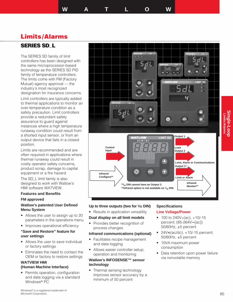
W A T L O W
85
Sin
gle-L
oo
pL
imits
/Alarm
s
SERIES SD_L
Limits /Alarms
The SERIES SD family of limitcontrollers has been designed withthe same microprocessor-basedtechnology as the SERIES SD PIDfamily of temperature controllers.The limits come with FM (FactoryMutual) agency approval — theindustry’s most recognizeddesignation for insurance concerns.
Limit controllers are typically addedto thermal applications to monitor anover-temperature condition as asafety precaution. Limit controllersprovide a redundant safetyassurance to guard againstinstances where a high temperaturerunaway condition could result froma shorted input sensor, or from anoutput device that fails in a closedposition.
Limits are recommended and areoften required in applications wherethermal runaway could result incostly operator safety concerns,product scrap, damage to capitalequipment or a fire hazard.
The SD_L limit family is alsodesigned to work with Watlow’s HMI software WATVIEW.
Features and Benefits
FM approved
Watlow’s patented User DefinedMenu System
• Allows the user to assign up to 20parameters in the operations menu
• Improves operational efficiency
“Save and Restore” feature foruser settings
• Allows the user to save individualor factory settings
• Eliminates the need to contact theOEM or factory to restore settings
WATVIEW HMI (Human Machine Interface)
• Permits operation, configurationand data logging via a standardWindows® PC
Up to three outputs (two for 1⁄32 DIN)
• Results in application versatility
Dual display on all limit models
• Provides better recognition ofprocess changes
Infrared communications (optional)
• Facilitates recipe managementand data logging
• Allows easier controller setup,operation and monitoring
Watlow’s INFOSENSE™ sensortechnology
• Thermal sensing technologyimproves sensor accuracy by aminimum of 50 percent
Specifications
Line Voltage/Power
• 100 to 240VÅ(ac), +10/-15percent; (85-264VÅ[ac]) 50/60Hz, ±5 percent
• 24Vı(ac/dc), +10/-15 percent;50/60Hz, ±5 percent
• 10VA maximum powerconsumption
• Data retention upon power failurevia nonvolatile memory
Windows® is a registered trademark ofMicrosoft Corporation.
RESET
2 31LIMIT SD
2 32 31
*1/32 DIN cannot have an Output 3.**Infrared option is not available on 1/32 DIN.
ControlInput Output 2
InfraredMonitor**
Output 1
Limit
Limit, Alarm or CommunicationsOutput 3
Limit or Alarm
*
InfraredConfigure**

1⁄32 DIN 97.8 mm 52.6 mm 29.7 mm(3.85 in.) (2.07 in.) (1.17 in.)
1⁄16 DIN 97.8 mm 52.1 mm 52.1 mm(3.85 in.) (2.05 in.) (2.05 in.)
1⁄8 DIN 97.8 mm 52.8 mm 99.8 mmVertical (3.85 in.) (2.08 in.) (3.93 in.)
1⁄8 DIN 97.8 mm 99.8 mm 52.8 mmHorizontal (3.85 in.) (3.93 in.) (2.08 in.)
1⁄4 DIN 101.1 mm 99.8 mm 99.8 mm(3.98 in.) (3.93 in.) (3.93 in.)
86
Limits /AlarmsSERIES SD_L
Environment
• -18 to 65°C (0 to 149°F) operatingtemperature
• -40 to 85°C (-40 to 185°F) storagetemperature
• 0 to 90 percent RH, non-condensing
Accuracy
• Calibration accuracy and sensorconformity: ±0.1 percent of span,±1°C @ the calibrated ambienttemperature and rated linevoltage
• Calibration ambient temperature= 25°C ±3°C (77°F ±5°F)
• Accuracy span: 540°C (1000°F)minimum
• Temperature stability: ±0.1°C/°C(±0.2°F/°F) rise in ambient maximum
Agency Approvals
• FM and NEMA 4X/IP65
• UL® 3121, C-UL®‚ CSA, CE foroutputs 2 and 3
• NSF for Type J, K, T and Ethermocouples
Controller
• Microprocessor based user-selectable control modes
• Single universal input, up to threeoutputs
• Control sampling rates: input = 6.5Hz, display = 10Hz,outputs = 6.5Hz
Operator Interface
• Dual 4 digit, 7 segment LEDdisplays
• Advance, infinity and up downkeys
• Optional IrDA infrared port (not available on 1⁄32 DIN)
• Isolated EIA-485 Modbus™ serialcommunications
Wiring Termination -Touch SafeTerminals
• Input power and control outputs12 to 22 AWG
• Sensor inputs and processoutputs 20 to 28 AWG
Universal Input
• Thermocouple, grounded orungrounded sensors
• RTD 2- or 3-wire, platinum, 100Ω@ 0°C calibration to DIN-curve (0.00385 Ω/Ω/°C)
• Process, 0-20mA @ 100Ω, or 0-10VÎ(dc) @ 20kΩ inputimpedance; Scalable
• Inverse scaling
• >20MΩ input impedance
• Maximum of 20Ω sourceresistance
Allowable Operating RangeType J: 0 to 815°C
(32 to 1500°F)Type K: -200 to 1370°C
(-328 to 2500°F)Type T: -200 to 400°C
(-328 to 750°F)Type N: 0 to 1300°C
(32 to 2372°F)Type E: -200 to 800°C
(-328 to 1470°F)Type C: 0 to 2315°C
(32 to 4200°F)
Type D: 0 to 2315°C(32 to 4200°F)
Type PTII: 0 to 1395°C(32 to 2543°F)
Type R: 0 to 1760°C(32 to 3200°F)
Type S: 0 to 1760°C(32 to 3200°F)
Type B: 0 to 1816°C(32 to 3300°F)
RTD (DIN): -200 to 800°C(-328 to 1472°F)
Process:- 1999 to 9999 units
Control Outputs
Output 1
• Electromechanical relay. Form A,rated 2A @ 120VÅ(ac), or240VÅ(ac) or 30VÎ(dc)
Output 2
• Electromechanical relay or E/A485 comms, or switched DC, or SSR
Output 3
• (not available on 1⁄32 DIN) 5 ampForm C EM-relay, or SSR, universal process, or switched DC
Specifications Cont.
DIN Size Behind Panel Width Height(max.)
Modbus™ is a trademark of AEG SchneiderAutomation, Inc.
Dimensions

W A T L O W
87
Sin
gle-L
oo
pL
imits
/Alarm
s
SERIES SD_L
Limits /Alarms
WATVIEW HMIWATVIEW, Watlow’s Windows®
based HMI (Human Machine Inter-face) software, supports the SERIESSD controllers. The software can beused to setup, monitor and edit thevalues of controller parameters, tomonitor and manage alarms and tolog and graph process data.
Oven
LimitSensor
TemperatureSensor
Output 1Input 1
Output 2
HeatersAlarm
Form C Relay
2 3 %2 31 %1 2 3 %
RESET
2 31
SERIES SD PID SERIES SD Limit
SD LIMIT SDLIMIT SD
Infrared Communications
The Infrared Data Communications(IDC) option is available on allSERIES SD controller models exceptthe 1⁄32 DIN and can support completeSERIES SD parameter configurationand operation. The IDC optionsupports wireless communicationswith PDAs (personal digital assistants)or other devices equipped with
infrared communications that supportthe Infrared Data Association (IrDA)1.0 Standard.
The actual user interface orconfiguration is dependent on themaster device application software.A source for this software is InstantHMI from Software Horizons. For more information, visitwww.instanthmi.com/watlow.
Advantages of IDC includeautomated logging of key processvariables, increased accuracyand ease of use for recipe or con-figuration setups. Infrared datacommunications enhances controllerdata exchange in physicallyrestricting environments (such assemiconductor clean rooms,governmental radio-active test labsor those hard to reach areas) andreduces the use of paper to recordinstrument information as well ashuman transposition errors.
Typical Block Diagram
Note: Consult user manual for proper wiring.
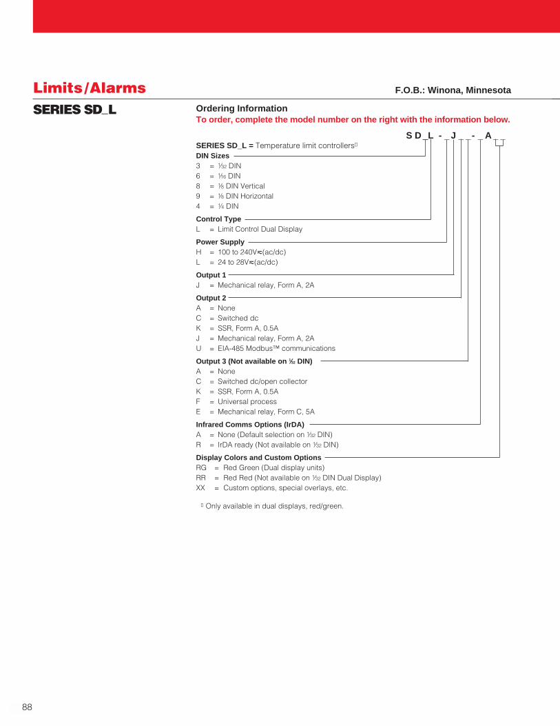
88
Limits /AlarmsSERIES SD_L Ordering Information
To order, complete the model number on the right with the information below.
S D L - _ J _ _- _ A _ _ SERIES SD_L = Temperature limit controllers①
DIN Sizes3 = 1⁄32 DIN6 = 1⁄16 DIN8 = 1⁄8 DIN Vertical9 = 1⁄8 DIN Horizontal4 = 1⁄4 DIN
Control TypeL = Limit Control Dual Display
Power SupplyH = 100 to 240Vı(ac/dc)L = 24 to 28Vı(ac/dc)
Output 1J = Mechanical relay, Form A, 2A
Output 2A = NoneC = Switched dcK = SSR, Form A, 0.5AJ = Mechanical relay, Form A, 2AU = EIA-485 Modbus™ communications
Output 3 (Not available on 1⁄32 DIN)A = NoneC = Switched dc/open collectorK = SSR, Form A, 0.5AF = Universal processE = Mechanical relay, Form C, 5A
Infrared Comms Options (IrDA)A = None (Default selection on 1⁄32 DIN)R = IrDA ready (Not available on 1⁄32 DIN)
Display Colors and Custom OptionsRG = Red Green (Dual display units)RR = Red Red (Not available on 1⁄32 DIN Dual Display)XX = Custom options, special overlays, etc.
① Only available in dual displays, red/green.
F.O.B.: Winona, Minnesota
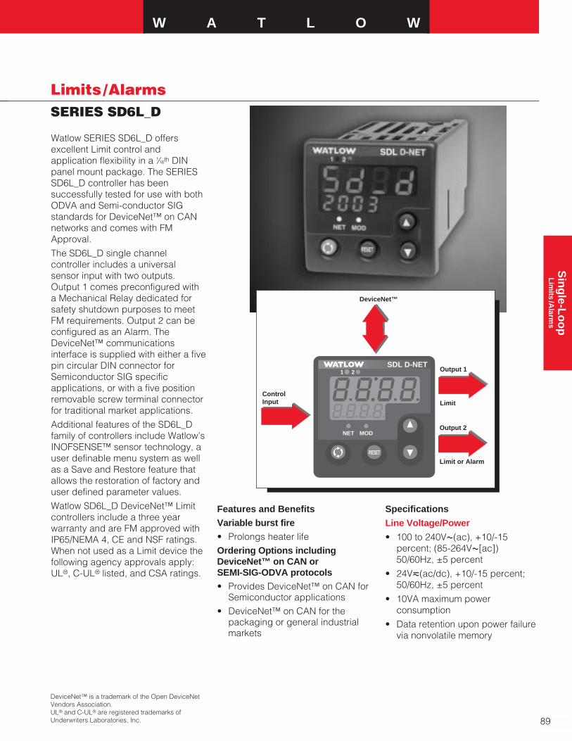
W A T L O W
89
Sin
gle-L
oo
pL
imits
/Alarm
s
SERIES SD6L_D
Limits /Alarms
Watlow SERIES SD6L_D offersexcellent Limit control andapplication flexibility in a 1⁄16th DINpanel mount package. The SERIESSD6L_D controller has beensuccessfully tested for use with bothODVA and Semi-conductor SIGstandards for DeviceNet™ on CANnetworks and comes with FMApproval.
The SD6L_D single channelcontroller includes a universalsensor input with two outputs.Output 1 comes preconfigured witha Mechanical Relay dedicated forsafety shutdown purposes to meetFM requirements. Output 2 can beconfigured as an Alarm. TheDeviceNet™ communicationsinterface is supplied with either a fivepin circular DIN connector forSemiconductor SIG specificapplications, or with a five positionremovable screw terminal connectorfor traditional market applications.
Additional features of the SD6L_Dfamily of controllers include Watlow’sINOFSENSE™ sensor technology, auser definable menu system as wellas a Save and Restore feature thatallows the restoration of factory anduser defined parameter values.
Watlow SD6L_D DeviceNet™ Limitcontrollers include a three yearwarranty and are FM approved withIP65/NEMA 4, CE and NSF ratings.When not used as a Limit device thefollowing agency approvals apply:UL®, C-UL® listed, and CSA ratings.
Features and BenefitsVariable burst fire• Prolongs heater lifeOrdering Options includingDeviceNet™ on CAN or SEMI-SIG-ODVA protocols• Provides DeviceNet™ on CAN for
Semiconductor applications• DeviceNet™ on CAN for the
packaging or general industrialmarkets
Specifications
Line Voltage/Power
• 100 to 240VÅ(ac), +10/-15percent; (85-264VÅ[ac]) 50/60Hz, ±5 percent
• 24Vı(ac/dc), +10/-15 percent;50/60Hz, ±5 percent
• 10VA maximum powerconsumption
• Data retention upon power failurevia nonvolatile memory
DeviceNet™ is a trademark of the Open DeviceNetVendors Association.UL® and C-UL® are registered trademarks ofUnderwriters Laboratories, Inc.
SDSD2 31
SDSD%
ControlInput
Output 1
Limit
Output 2
Limit or Alarm
DeviceNet™
RESET
21
NET MOD
21
NET MOD
SDL D-NET
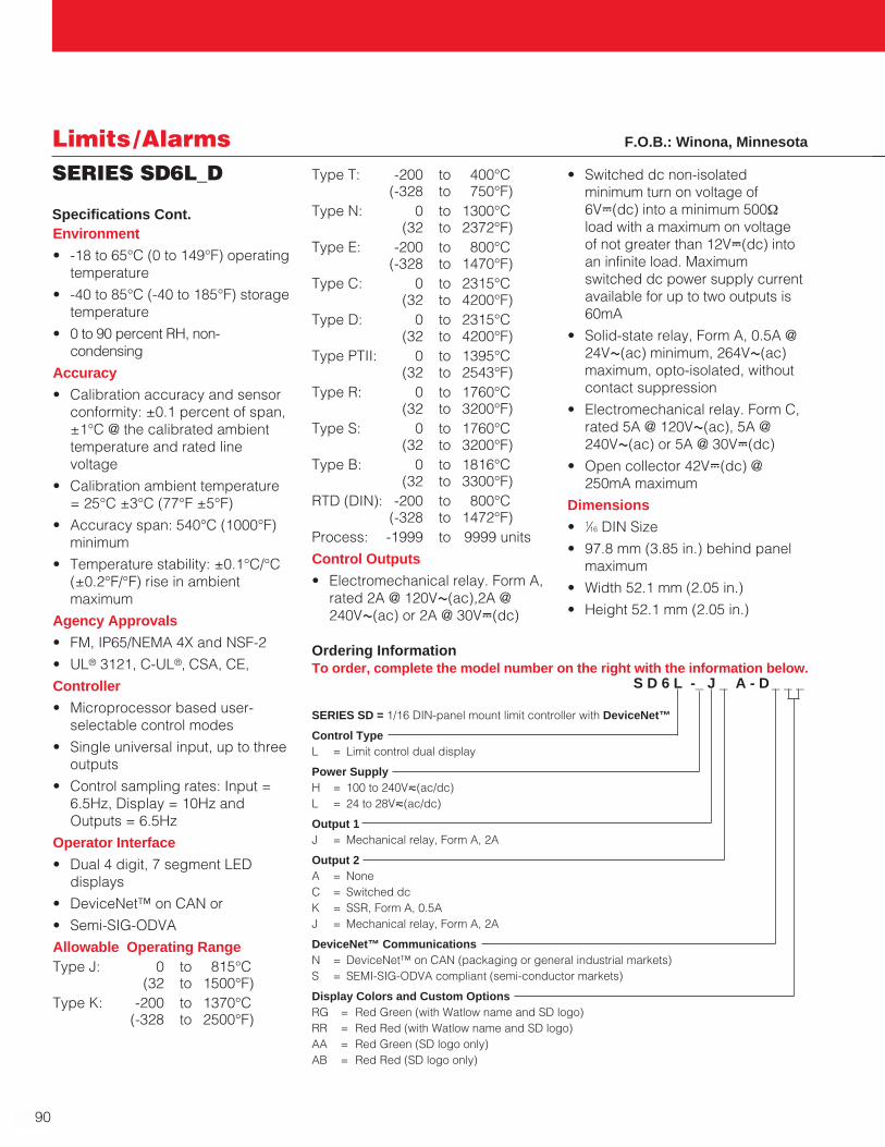
90
Limits /AlarmsSERIES SD6L_D
Environment
• -18 to 65°C (0 to 149°F) operatingtemperature
• -40 to 85°C (-40 to 185°F) storagetemperature
• 0 to 90 percent RH, non-condensing
Accuracy
• Calibration accuracy and sensorconformity: ±0.1 percent of span,±1°C @ the calibrated ambienttemperature and rated linevoltage
• Calibration ambient temperature= 25°C ±3°C (77°F ±5°F)
• Accuracy span: 540°C (1000°F)minimum
• Temperature stability: ±0.1°C/°C(±0.2°F/°F) rise in ambientmaximum
Agency Approvals
• FM, IP65/NEMA 4X and NSF-2
• UL® 3121, C-UL®‚ CSA, CE,
Controller
• Microprocessor based user-selectable control modes
• Single universal input, up to threeoutputs
• Control sampling rates: Input =6.5Hz, Display = 10Hz andOutputs = 6.5Hz
Operator Interface
• Dual 4 digit, 7 segment LEDdisplays
• DeviceNet™ on CAN or
• Semi-SIG-ODVA
Allowable Operating RangeType J: 0 to 815°C
(32 to 1500°F)Type K: -200 to 1370°C
(-328 to 2500°F)
Ordering InformationTo order, complete the model number on the right with the information below.
S D 6 L -_ J _ A - D _ _ _
SERIES SD = 1/16 DIN-panel mount limit controller with DeviceNet™
Control TypeL = Limit control dual display
Power SupplyH = 100 to 240Vı(ac/dc)L = 24 to 28Vı(ac/dc)
Output 1J = Mechanical relay, Form A, 2A
Output 2A = NoneC = Switched dcK = SSR, Form A, 0.5AJ = Mechanical relay, Form A, 2A
DeviceNet™ CommunicationsN = DeviceNet™ on CAN (packaging or general industrial markets)S = SEMI-SIG-ODVA compliant (semi-conductor markets)
Display Colors and Custom OptionsRG = Red Green (with Watlow name and SD logo)RR = Red Red (with Watlow name and SD logo)AA = Red Green (SD logo only)AB = Red Red (SD logo only)
Specifications Cont.
F.O.B.: Winona, Minnesota
Type T: -200 to 400°C(-328 to 750°F)
Type N: 0 to 1300°C(32 to 2372°F)
Type E: -200 to 800°C(-328 to 1470°F)
Type C: 0 to 2315°C(32 to 4200°F)
Type D: 0 to 2315°C(32 to 4200°F)
Type PTII: 0 to 1395°C(32 to 2543°F)
Type R: 0 to 1760°C(32 to 3200°F)
Type S: 0 to 1760°C(32 to 3200°F)
Type B: 0 to 1816°C(32 to 3300°F)
RTD (DIN): -200 to 800°C(-328 to 1472°F)
Process: -1999 to 9999 units
Control Outputs
• Electromechanical relay. Form A,rated 2A @ 120VÅ(ac),2A @240VÅ(ac) or 2A @ 30VÎ(dc)
• Switched dc non-isolatedminimum turn on voltage of6VÎ(dc) into a minimum 500Ωload with a maximum on voltageof not greater than 12VÎ(dc) intoan infinite load. Maximumswitched dc power supply currentavailable for up to two outputs is60mA
• Solid-state relay, Form A, 0.5A @24VÅ(ac) minimum, 264VÅ(ac)maximum, opto-isolated, withoutcontact suppression
• Electromechanical relay. Form C,rated 5A @ 120VÅ(ac), 5A @240VÅ(ac) or 5A @ 30VÎ(dc)
• Open collector 42VÎ(dc) @250mA maximum
Dimensions
• 1⁄16 DIN Size
• 97.8 mm (3.85 in.) behind panelmaximum
• Width 52.1 mm (2.05 in.)
• Height 52.1 mm (2.05 in.)

W A T L O W
91
Sin
gle-L
oo
pL
imits
/Alarm
s
SERIES 97
Limits /Alarms
Watlow’s SERIES 97 is a micro-processor-based controller with asingle input, second auxiliary inputand four outputs. Input 1 is used tomeasure temperature from a sensor.Input 2 can be utilized as a remotereset switch or a hardware lockoutswitch. With up to four outputs, thecontroller is versatile in handlingapplications that require a high/lowlimit, alarms, retransmit andcommunications. The control is souser friendly it can be set up todisplay safety and limit messagescreated by the end user to meet theexact application need.
The SERIES 97 limit controller isadded to thermal applications to limitover-temperature conditions. TheSERIES 97 limit controller providessafety assurance against instanceswhere a high temperature runawaycondition could occur from a shortedinput sensor or an output device thatcould fail in a closed position.
The SERIES 97 is recommended forany application where thermalrunaway could result in large productscrap costs, affect operator safety,cause damage to equipment orcreate a fire hazard.
The SERIES 97 is manufactured byISO 9001 registered Watlow Winonaand reliably backed up by a three-year warranty.
Features and Benefits
Programmable messages(Patented)
• Controller can be set up to displayuser programmed limit message
NEMA 4X (IP65)
• Water and corrosion resistant;front panel can be washed down
Microprocessor-based
• Accurate set point settings andquick output response
Second auxiliary input
• Remote reset capability
Four outputs
• Handles high/low limit, alarms,communication and retransmitrequirements
Software and hardware lockouts
• High security• Three-year warranty provides
Control Confidence®
Applications• Furnace and ovens
• Environmental chambers
• Semiconductor
• Food processing
• Boilers
• Laboratory equipment
Input 1Process
Input 2Remote Reset or Hardware Lockout
Output 1Limit Relay
Output 2Alarm
Output 3Alarm
Output 4Alarm, Analog or Communications
2 3 4LIMIT 97
1
RESET

92
Limits /AlarmsSERIES 97
Specifications
Controller
• Microprocessor-based
• Universal input 1, auxiliary input 2,4 outputs
• Input sample period; Single input10Hz (100 msec), dual input 5Hz(200 msec) digital filter adjustable
• Display update; 2Hz (500 msec),time filter adjustable
• Input/Output/Communicationisolation
• Displayed in °C, °F
Operator Interface
• Dual 4-digit LED displays: upper10.2 mm (0.4 in.), lower 6.2 mm(0.244 in.)
• Advance, Up Arrow, Down Arrow,Reset tactile keys
Standard Conditions ForSpecifications
• Ambient temperature 25°C (77°F)±3°C, rated line voltage, 50 to60Hz, 0 to 90 percent RH non-condensing, 15 minute warm-up
Universal Input 1
Thermocouple
• Type J, K, T, N, C (W5), E, PTII, D(W3), B, R, S thermocouple types
• >20MΩ input impedance
• Maximum 20Ω source resistance
• 30mA open detection bias
RTD
• 2- or 3-wire platinum, 100Ω
• JIS and DIN-curves
• Whole or tenth degree indication
• 150µA nominal RTD excitationcurrent
Input 2
Event Input
• Contact or voltage
• 20KΩ input impedance
• Voltage input: event high state 3to 36VÎ(dc), event low state 0 to2VÎ(dc)
• Resistance/contact input: eventhigh state > 23kΩ, event low state0 to 2kΩ
Output Types
Open Collector/Switched DC
• Open collector configuration:Maximum voltage 42VÎ(dc)Maximum current 200mA Maximum “on” resistance 1.1ΩMaximum off state leakagecurrent 100µA
• Switched dc configuration:Switched dc supply voltage 22 to28VÎ(dc) dc supply currentlimited to 30mA
Solid State Relay
• Optically isolated
• Zero cross switched
• Without contact suppression
• Minimum load current 0.5mA rms
• Maximum current 0.5A rms at 20to 280VÅ(ac)
• Maximum off state leakagecurrent 10µA rms
• For resistive loads only, must useRC suppression for inductiveloads
Electromechanical Relay
• Form C contact configuration
• Minimum load current 10mA @5VÎ(dc)
• Rated resistive and inductiveloads: 2A @ 250VÅ(ac) or30VÎ(dc) maximum
• Electrical life 100,000 cycles atrated current
• For resistive loads only, must useRC suppression for inductiveloads
Retransmit
• Range selectable: 0-20mA, 4-20mA, 0-5VÎ(dc), 1-5VÎ(dc), 0-10VÎ(dc)
• 0 to 10VÎ(dc) voltage output intoa 1,000Ω minimum loadresistance
• 0 to 20mA current output into an800Ω maximum load resistance
• Resolution:
VÎ(dc) ranges = 2.5mV nominal
mA ranges = 5µA nominal
• Calibration accuracy:
VÎ(dc) ranges = ±15mV
mA ranges = ±30µA
• Temperature stability 100ppm/°C
Communications
• EIA/TIA-485, EIA/TIA-232
• Opto-isolated
• Modbus™ RTU protocol
• 1200, 2400, 4800, 9600, 19200baud rates
• 32 maximum units can beconnected (With additional 485repeater hardware, up to 247units may be connected)
Accuracy
• Input rangesType J: 0 to 750°C
(32 to 1382°F)Type K: -200 to 1250°C
(-328 to 2282°F)Type T: -200 to 350°C
(-328 to 662°F)Type N: 0 to 1250°C
(32 to 2282°F)Type E: -200 to 900°C
(-328 to 1470°F)Type C(W5): 0 to 2315°C
(32 to 4200°F)Type D(W3): 0 to 2315°C
(32 to 4200°F)Type PTII: 0 to 1393°C
(32 to 2540°F)Type R: 0 to 1450°C
(32 to 2642°F)Type S: 0 to 1450°C
(32 to 2642°F)Type B: 870 to 1700°C
(1598 to 3092°F)DIN: -200 to 800°C
(-328 to 1472°F)JIS: -200 to 630°C
(-328 to 1166°F)
Modbus™ is a trademark of AEG SchneiderAutomation.

W A T L O W
93
Sin
gle-L
oo
pL
imits
/Alarm
s
SERIES 97
Limits /Alarms
Thermocouple Inputs
• Calibration accuracy ±0.1 percentof span ±1˚C at standardconditions
Exceptions: Type T: 0.12 percent of span for -200°C to -50°C (-328°F to -58°F)
Types R and S: 0.15 percent ofspan for 0°C to 100°C (32°F to212°F)
Types B: 0.24 percent of span for870°C to 1700°C (1598°F to3092°F)
• Accuracy span: 540°C (1000°F)minimum
• Temperature stability: ±0.1° perdegree change in ambient
RTD Inputs
• Calibration accuracy ±0.1 percentof span ±1˚C at standardconditions
• Accuracy span: 540°C (1000°F)minimum
• Temperature stability: ±0.05° perdegree change in ambient
Agency Approvals
• FM Class 3545, File # J.I.1B5A6.AF
• NEMA 4X, IP65
• CE 89/336/EEC, electromagneticcompatibility directiveCE 73/23/EEC, low-voltagedirective
Terminals
• Touch safe
• 22 to 12 AWG
Power
• 100-240VÅ(ac) +10 percent, -15 percent; 50/60Hz, ±5 percent
• 24-28VÅ(ac) or VÎ(dc) +10percent, -15 percent; 50/60Hz, ±5 percent
• 7.0VA maximum powerconsumption
• Data retention upon power failurevia nonvolatile memory
Operating Environment
• 0 to 65°C (32 to 149°F)
• 0 to 90 percent RH, non-condensing
• Storage temperature: -40 to 85°C(-40 to 185°F)
Dimensions
• Width 52 mm (2.05 in.)
• Height 52 mm (2.05 in.)
• Length 107 mm (4.2 in.)
• Depth behind panel surface 98.4 mm (3.875 in.)
• Approximate controller weight 0.2 kg (0.4 lbs)
Allowable Operating RangesType J: 1.0 0 to 815°C
(32 to 1500°F)0.1 0 to 815°C
(32 to 1500°F)Type K: 1.0 -270 to 1370°C
(-454 to 2500°F)0.1 -200 to 1000°C
(-328 to 1832°F)Type T: 1.0 -270 to 400°C
(-454 to 750°F)0.1 -200 to 400°C
(-328 to 750°F)Type N: 1.0 0 to 1300°C
(32 to 2372°F)0.1 0 to 1000°C
(32 to 1832°F)Type E: 1.0 -270 to 1800°C
(-454 to 3272°F)0.1 -110 to 800°C
(-166 to 1472°F)Type C: 1.0 0 to 2315°C
(32 to 4200°F)0.1 0 to 1000°C
(32 to 1832°F)Type D: 1.0 0 to 2315°C
(32 to 4200°F)0.1 0 to 1000°C
(32 to 1832°F)Type PTII: 1.0 0 to 1395°C
(32 to 2543°F)0.1 0 to 1000°C
(32 to 1832°F)Type R: 1.0 0 to 1760°C
(32 to 3200°F)Type S: 1.0 0 to 1760°C
(32 to 3200°F)Type B: 1.0 0 to 1816°C
(32 to 3300°F)DIN 1.0 -200 to 800°C
(-328 to 1472°F)0.1 -200 to 800°C
(-328 to 1472°F)JIS 1.0 -200 to 630°C
(-328 to 1166°F)0.1 -200 to 630°C
(-328 to 1166°F)
Specifications Cont.
Functionality Matrix
Note: These specifications are subject to change without prior notice.
High/ High/ 232Universal Low Low 485
Input Event Limit Alarm Retransmit CommInput 1Input 2Output 1Output 2Output 3Output 4
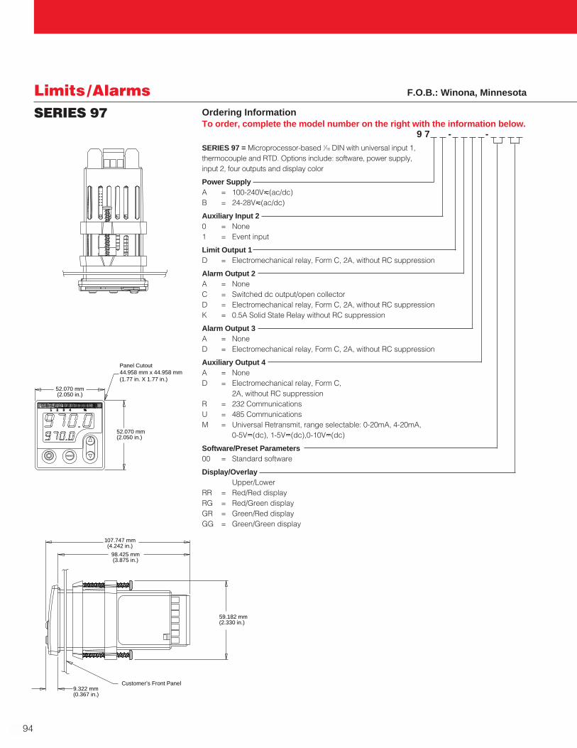
94
Limits /AlarmsSERIES 97 Ordering Information
To order, complete the model number on the right with the information below.9 7 - -
SERIES 97 = Microprocessor-based 1⁄16 DIN with universal input 1, thermocouple and RTD. Options include: software, power supply, input 2, four outputs and display color
Power SupplyA = 100-240Vı(ac/dc)B = 24-28Vı(ac/dc)
Auxiliary Input 20 = None1 = Event input
Limit Output 1D = Electromechanical relay, Form C, 2A, without RC suppression
Alarm Output 2A = NoneC = Switched dc output/open collectorD = Electromechanical relay, Form C, 2A, without RC suppressionK = 0.5A Solid State Relay without RC suppression
Alarm Output 3A = NoneD = Electromechanical relay, Form C, 2A, without RC suppression
Auxiliary Output 4A = NoneD = Electromechanical relay, Form C,
2A, without RC suppressionR = 232 CommunicationsU = 485 CommunicationsM = Universal Retransmit, range selectable: 0-20mA, 4-20mA,
0-5VÎ(dc), 1-5VÎ(dc),0-10VÎ(dc)
Software/Preset Parameters00 = Standard software
Display/OverlayUpper/Lower
RR = Red/Red displayRG = Red/Green displayGR = Green/Red displayGG = Green/Green display
2 3 4 %96
1
52.070 mm(2.050 in.)
52.070 mm(2.050 in.)
Panel Cutout44.958 mm x 44.958 mm(1.77 in. X 1.77 in.)
RESET
107.747 mm(4.242 in.)
59.182 mm(2.330 in.)
98.425 mm(3.875 in.)
9.322 mm(0.367 in.)
Customer’s Front Panel
F.O.B.: Winona, Minnesota
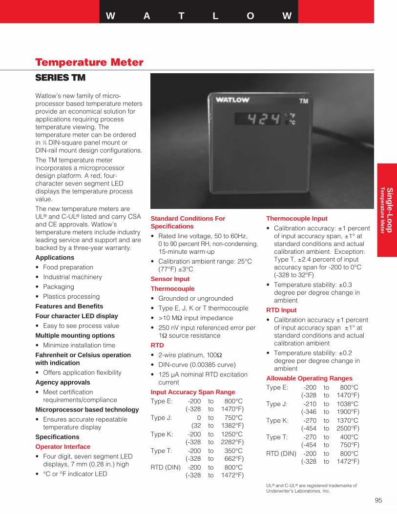
W A T L O W
95
Sin
gle-L
oo
pT
emp
erature M
eter
SERIES TM
Temperature Meter
Watlow’s new family of micro-processor based temperature metersprovide an economical solution forapplications requiring processtemperature viewing. Thetemperature meter can be ordered in 1⁄8 DIN-square panel mount or DIN-rail mount design configurations.
The TM temperature meterincorporates a microprocessordesign platform. A red, four-character seven segment LEDdisplays the temperature processvalue.
The new temperature meters areUL® and C-UL® listed and carry CSAand CE approvals. Watlow’stemperature meters include industryleading service and support and arebacked by a three-year warranty.
Applications
• Food preparation
• Industrial machinery
• Packaging
• Plastics processing
Features and Benefits
Four character LED display
• Easy to see process value
Multiple mounting options
• Minimize installation time
Fahrenheit or Celsius operationwith indication
• Offers application flexibility
Agency approvals
• Meet certificationrequirements/compliance
Microprocessor based technology
• Ensures accurate repeatabletemperature display
Specifications
Operator Interface
• Four digit, seven segment LEDdisplays, 7 mm (0.28 in.) high
• °C or °F indicator LED
Standard Conditions ForSpecifications
• Rated line voltage, 50 to 60Hz, 0 to 90 percent RH, non-condensing,15-minute warm-up
• Calibration ambient range: 25°C(77°F) ±3°C
Sensor Input
Thermocouple
• Grounded or ungrounded
• Type E, J, K or T thermocouple
• >10 MΩ input impedance
• 250 nV input referenced error per1Ω source resistance
RTD
• 2-wire platinum, 100Ω
• DIN-curve (0.00385 curve)
• 125 µA nominal RTD excitationcurrent
Input Accuracy Span RangeType E: -200 to 800°C
(-328 to 1470°F)Type J: 0 to 750°C
(32 to 1382°F)Type K: -200 to 1250°C
(-328 to 2282°F)Type T: -200 to 350°C
(-328 to 662°F)RTD (DIN) -200 to 800°C
(-328 to 1472°F)
Thermocouple Input
• Calibration accuracy: ±1 percentof input accuracy span, ±1° atstandard conditions and actualcalibration ambient. Exception:Type T, ±2.4 percent of inputaccuracy span for -200 to 0°C (-328 to 32°F)
• Temperature stability: ±0.3degree per degree change inambient
RTD Input
• Calibration accuracy ±1 percentof input accuracy span ±1° atstandard conditions and actualcalibration ambient
• Temperature stability: ±0.2degree per degree change inambient
Allowable Operating RangesType E: -200 to 800°C
(-328 to 1470°F) Type J: -210 to 1038°C
(-346 to 1900°F)Type K: -270 to 1370°C
(-454 to 2500°F)Type T: -270 to 400°C
(-454 to 750°F)RTD (DIN) -200 to 800°C
(-328 to 1472°F)
UL® and C-UL® are registered trademarks ofUnderwriter’s Laboratories, Inc.

96
Temperature MeterSERIES TM
Specifications Cont.
Agency Approvals
• UL® 60730-1 RecognizedTemperature Controller andIndicator
• UL® 197 Reviewed for use incooking appliances
• ANSI Z21.23 Gas ApplianceThermostat approval
• Temperature Control andIndicator CSA 22.2 No. 24
Terminals
• 6.3 mm (0.25 in.) quick connect,push on terminal
Power
• 24VÅ(ac) +10 percent; -15 percent; 50/60Hz, ±5 percent
• 120VÅ(ac) +10 percent; -15 percent; 50/60Hz, ±5 percent
• 230 to 240VÅ(ac) +10 percent; -15 percent; 50/60Hz, ±5 percent
• 10VA maximum powerconsumption
• Data retention upon power failurevia nonvolatile memory
Operating Environment
• 0 to 70°C (32 to 158°F)
• 0 to 90 percent RH, non-condensing
• Storage temperature: -40 to 85°C(-40 to 185°F)
Ordering InformationTo order, complete the model number on the right with the information below.
T M A A A A A A A A ASERIES TM = Indicator only, four character, seven segment display
Power SupplyB = 120VÅ(ac) D = 230 to 240VÅ(ac)F = 24VÅ(ac)
Package1 = Panel mount square 1⁄8 DIN 2 = DIN-rail mount
Sensor Type and ScaleH = T/C Type J Fahrenheit
(-346 to 1900˚F)J = T/C Type J Celsius
(-210 to 1038˚C)K = T/C Type K Fahrenheit
(-454 to 2500˚F)L = T/C Type K Celsius
(-270 to 1370˚C)M = T/C Type T Fahrenheit
(-454 to 750˚F)N = T/C Type T Celsius
(-270 to 400˚C)P = RTD Fahrenheit
(-328 to 1472˚F)R = RTD Celsius
(-200 to 800˚C)S = T/C Type E Fahrenheit
(-328 to 1470˚F)T = T/C Type E Celsius
(-200 to 800˚C)
Overlay/Customs OptionsA = Standard
DIN-rail 78.1 mm 112.3 mm 90.7 mm(3.08 in.) (4.42 in.) (3.57 in.)
Square 1⁄8 72.4 mm 72.4 mm Behind panelDIN-panel (2.85 in.) (2.85 in.) 51.7 mm
(2.04 in.)
Style Width Height Depth
F.O.B.: Winona, Minnesota
Dimensions
• DIN-rail model can be DIN-rail orchassis mount
DIN-rail spec DIN 50022, 35 mm x7.5 mm (1.38 in. x 0.30 in.)

W A T L O W
97
Sin
gle
-Lo
op
A
ccessories
Single-LoopControllersAccessories
Current Transformer16-0246a 0 to 50 amps: 0 to 50mA16-0008b 75 amp: 5 amp16-0044 100 amp: 5 amp16-0072 125 amp: 5 amp16-0008 150 amp: 5 amp16-0045 200 amp: 5 amp16-0073 300 amp: 5 amp
Interstage Transformer16-0176 5 amp: 20mA
Code No. Current Ratio
Note: An interstage transformer (code no. 16-0176) is required with anycurrent transformer rated 75 amps or above.1Superceeds code numbers 16-0230, 16-0231, 16-0232, 16-0233.2Use two wire passes through the currenttransformer 16-0008 for 75 amp applications.
Current Transformers
Panel Mount Adapter PlatesPanel mount adapter plates providea convenient, cost saving way tomodify existing controller panels.Available in popular DIN and non-DIN sizes, adapter plates makechanging out old, larger sizetemperature controllers with moresophisticated, compact controllerseasy. Simply complete the build-a-code with the specifications yourequire.
F.O.B.: Winona, Minnesota
The following accessories andreplacement parts are available toenhance the application and serviceof Watlow temperature controllers.
To order, simply identify thespecification of the desired part anduse its code number.
Consult your Watlow representativefor availability.
Ordering Information
To order, complete the code number to the right with the information below:Adapter plates to reduce panel cutout size. 0 2 1 6 - 0 8 _ _ - P 0 0 _Adapter Plate Size and Configuration
65 = 1⁄4 DIN to single/horizontal or vertical 1⁄8 DIN66 = 1⁄4 DIN to single 1⁄16 DIN95 = 1⁄4 DIN to single/horizontal 1⁄32 DIN96 = 1⁄4 DIN to dual/ horizontal 1⁄32 DIN67 = Vertical 1⁄8 DIN to 1⁄16 DIN97 = Vertical 1⁄8 DIN to single horizontal 1⁄32 DIN98 = Vertical 1⁄8 DIN to dual horizontal 1⁄32 DIN99 = Horizontal 1⁄8 DIN to horizontal 1⁄32 DIN85a = 95 x 170 mm (3.75 in. x 6.75 in.) blank plate/no cutout86a = 95 x 170 mm (3.75 in. x 6.75 in.) to dual 1⁄16 DIN87a = 95 x 170 mm (3.75 in. x 6.75 in.) to single 1⁄16 DIN88a = 95 x 170 mm (3.75 in. x 6.75 in.) to single 1⁄8 DINFinish
2 = Black anodize3 = Stainless steel
aAvailable in stainless steel finish only.

98
Single-LoopControllersAccessories
Description Code No.
SERIES 981/2/3/4/6/7/8/9Mounting collar 0822-0438-0000Mounting bracket Z100-0636-0000Protective terminal cover 0822-0444-0000Internal bezel gasket 0830-0425-0000Case gasket 0830-0424-0000Electromechanical relaya 0003-0103-0000Solid state relaya 0842-0164-0000Quencharc® RC suppressor 0804-0147-0000Noise Suppression DevicesMOV, 150VÅ(ac), 20 joule 0802-0273-0000Quencharc® RC suppressor 0804-0147-0000
Replacement Parts
aSolder-in part. Solder-in parts require opening the controller and soldering the component intothe circuit board. Note: opening the controller for installation will void warranty! To retainwarranty protection, Watlow Winona can install component. Consult factory for details.
Quencharc® is a registered trademark of ITW Paktron, Division of Illinois Tool Works.

Mu
lti-Lo
op
A
uto
-Tu
nin
g P
IDW A T L O W
SERIES 998/999
Auto-Tuning PIDControllers
The Watlow SERIES 998 (vertical)and the SERIES 999 (horizontal) are 1⁄8 DIN dual channel processcontrollers offering two channels ofPID control in a single package. Withup to six outputs, this controller iswell suited for most applicationswhere multiple process parametersneed controlling.
The SERIES 998/999 features a NEMA 4Xb (IP65) front panel towithstand wet and corrosiveenvironments. Compact four-inchcase depth and palm-safe wiringterminals make installation easy.
The two universal signal conditionerinputs accept 11 differentthermocouple types, RTD andscaleable process inputs. A singleevent input allows operators to turncontrol outputs off, lock out the frontpanel or reset the alarm remotely.
Output options provide applicationflexibility:
• Dual heat/cool outputs perchannel
• Optional two alarm outputs
• Optional retransmit output
• Optional serial communications
Performance Capabilities
• Accuracy to ±0.1 percent of span
• Operating environment 0 to 65°C (32 to 149°F)
Features and BenefitsTwo analog inputs, four controloutputs and two alarm outputs
• Provide two complete controlloops in a single package
Auto-tuning
• For one step tuning of systemparameters for each channel
Optional dual alarm outputs
• User-selectable to monitor eitherchannel
Optional serial communications
• Provides remote operation using ahost computer
Hardware and software lockoutoptions
• Offer several parameter levels ofoperator security
UL®, CE, NEMA 4X1 (IP65) frontpanel
• Provides corrosion resistance
5Hz sampling rate per channel andvariable time base burst-firecontrol
• Delivers smooth, accurateprocess control
Three-year warranty2
• Provides Control Confidence®
Applications• Any process requiring multiple
control loops
• Complex process furnaces
• Environmental chambers
• Processes needing control/monitoring from a computer
1 To effect NEMA 4X (IP65) rating requires aminimum mounting panel thickness of1.5 mm (0.06 in.) and surface finish not rougherthan 0.000812 mm (0.000032 in.).
2 Electromechanical relays warranted for 100,000closures only. Solid state switching devicesrecommended for applications requiring fastcycle times or extended service life.
TL WWA
PROCESS
1A 2A 1B 2B
CH A
CH BDISPLAY
SERIES 998
MODE
AUTOMAN
Input 1Type B, C, D, E, J, K, N, R, S, T or Pt 2Thermocouple, DIN/JIS RTD orProcess
Input 3Digital Event
Input 2Type B, C, D, E, J, K, N, R, S, T or Pt 2Thermocouple, DIN/JIS RTD orProcess
Output Channel ADual OutputsClosed Loop PID, on-off ControlOpen Loop Percent Power
Output Channel BDual OutputsClosed Loop PID, on-off ControlOpen Loop Percent Power
Output 3AlarmTransmitter Power SupplyAnalog Retransmit
Output 4AlarmTransmitter Power SupplyAnalog RetransmitSerial Communications
Auto-tuneHeat/Cool
Percent Power
UL® is a registered trademark of Underwriter’sLaboratories, Inc.
99
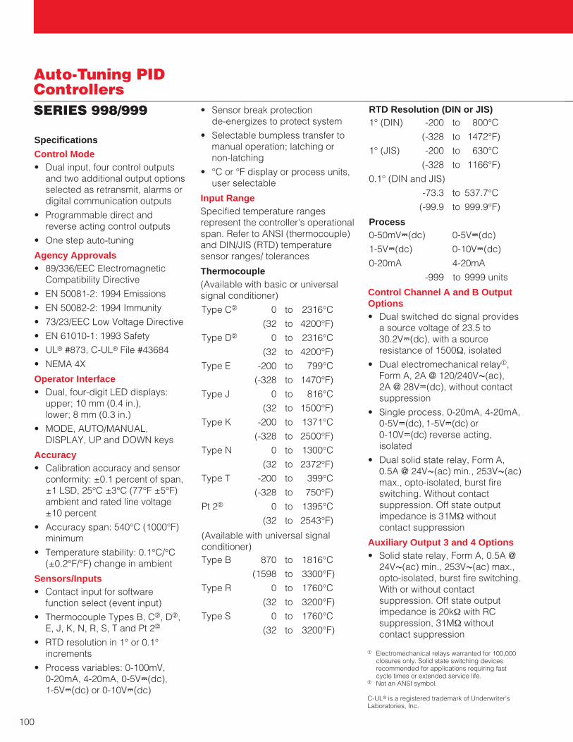
Auto-Tuning PIDControllersSERIES 998/999
Specifications
Control Mode• Dual input, four control outputs
and two additional output optionsselected as retransmit, alarms ordigital communication outputs
• Programmable direct and reverse acting control outputs
• One step auto-tuning
Agency Approvals• 89/336/EEC Electromagnetic
Compatibility Directive
• EN 50081-2: 1994 Emissions
• EN 50082-2: 1994 Immunity
• 73/23/EEC Low Voltage Directive
• EN 61010-1: 1993 Safety
• UL® #873, C-UL® File #43684
• NEMA 4X
Operator Interface• Dual, four-digit LED displays:
upper; 10 mm (0.4 in.), lower; 8 mm (0.3 in.)
• MODE, AUTO/MANUAL,DISPLAY, UP and DOWN keys
Accuracy• Calibration accuracy and sensor
conformity: ±0.1 percent of span, ±1 LSD, 25°C ±3°C (77°F ±5°F)ambient and rated line voltage±10 percent
• Accuracy span: 540°C (1000°F) minimum
• Temperature stability: 0.1°C/°C(±0.2°F/°F) change in ambient
Sensors/Inputs• Contact input for software
function select (event input)
• Thermocouple Types B, Cb, Db,E, J, K, N, R, S, T and Pt 22
• RTD resolution in 1° or 0.1°increments
• Process variables: 0-100mV, 0-20mA, 4-20mA, 0-5VÎ(dc), 1-5VÎ(dc) or 0-10VÎ(dc)
• Sensor break protection de-energizes to protect system
• Selectable bumpless transfer tomanual operation; latching or non-latching
• °C or °F display or process units,user selectable
Input RangeSpecified temperature rangesrepresent the controller's operationalspan. Refer to ANSI (thermocouple)and DIN/JIS (RTD) temperaturesensor ranges/ tolerances
Thermocouple(Available with basic or universalsignal conditioner)
Type Cb 0 to 2316°C
(32 to 4200°F)
Type Db 0 to 2316°C
(32 to 4200°F)
Type E -200 to 799°C
(-328 to 1470°F)
Type J 0 to 816°C
(32 to 1500°F)
Type K -200 to 1371°C
(-328 to 2500°F)
Type N 0 to 1300°C
(32 to 2372°F)
Type T -200 to 399°C
(-328 to 750°F)
Pt 2b 0 to 1395°C
(32 to 2543°F)
(Available with universal signalconditioner)Type B 870 to 1816°C
(1598 to 3300°F)
Type R 0 to 1760°C
(32 to 3200°F)
Type S 0 to 1760°C
(32 to 3200°F)
RTD Resolution (DIN or JIS)1° (DIN) -200 to 800°C
(-328 to 1472°F)
1° (JIS) -200 to 630°C
(-328 to 1166°F)
0.1° (DIN and JIS)
-73.3 to 537.7°C
(-99.9 to 999.9°F)
Process0-50mVÎ(dc) 0-5VÎ(dc)
1-5VÎ(dc) 0-10VÎ(dc)
0-20mA 4-20mA
-999 to 9999 units
Control Channel A and B OutputOptions• Dual switched dc signal provides
a source voltage of 23.5 to30.2VÎ(dc), with a source resistance of 1500Ω, isolated
• Dual electromechanical relaya,Form A, 2A @ 120/240VÅ(ac), 2A @ 28VÎ(dc), without contactsuppression
• Single process, 0-20mA, 4-20mA,0-5VÎ(dc), 1-5VÎ(dc) or0-10VÎ(dc) reverse acting,isolated
• Dual solid state relay, Form A,0.5A @ 24VÅ(ac) min., 253VÅ(ac)max., opto-isolated, burst fireswitching. Without contactsuppression. Off state outputimpedance is 31MΩ withoutcontact suppression
Auxiliary Output 3 and 4 Options• Solid state relay, Form A, 0.5A @
24VÅ(ac) min., 253VÅ(ac) max.,opto-isolated, burst fire switching.With or without contactsuppression. Off state outputimpedance is 20kΩ with RCsuppression, 31MΩ withoutcontact suppression
a Electromechanical relays warranted for 100,000closures only. Solid state switching devicesrecommended for applications requiring fastcycle times or extended service life.
b Not an ANSI symbol.
C-UL® is a registered trademark of Underwriter’sLaboratories, Inc.
100
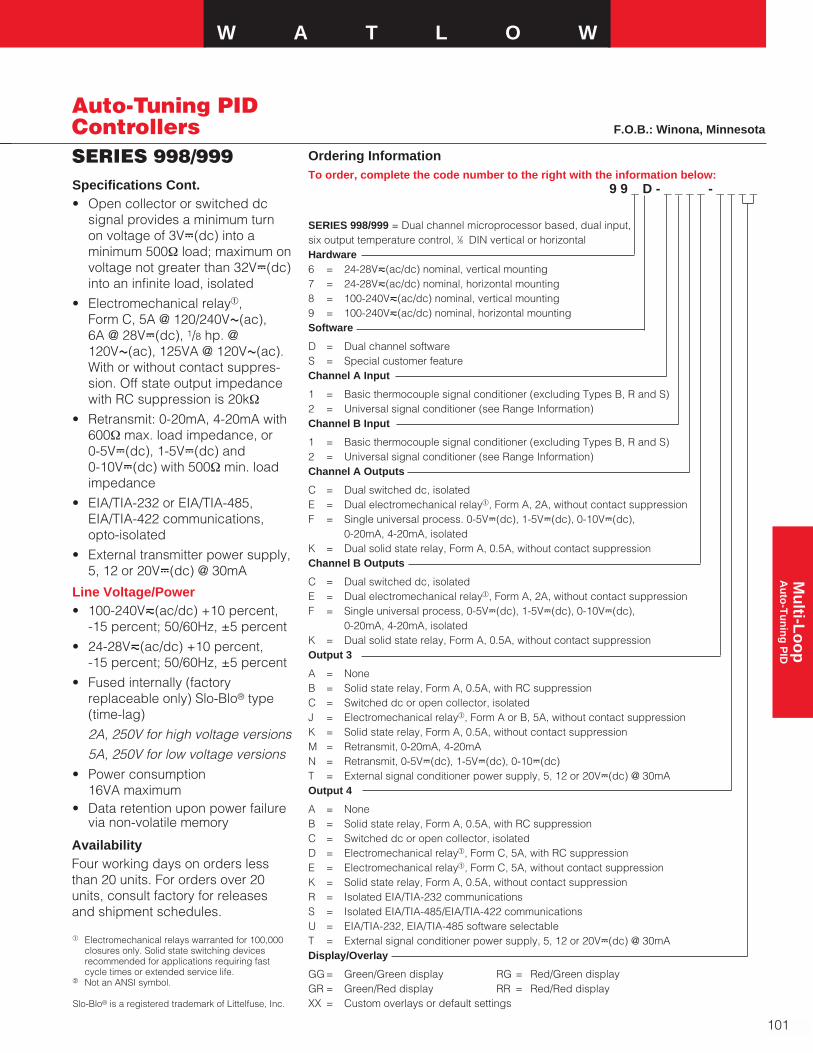
Mu
lti-Lo
op
A
uto
-Tu
nin
g P
IDW A T L O W
101
SERIES 998/999
Auto-Tuning PIDControllers
Ordering InformationTo order, complete the code number to the right with the information below:
9 9 _ D - _ _ _ _ - _ _ _ _
SERIES 998/999 = Dual channel microprocessor based, dual input,six output temperature control, 1⁄8 DIN vertical or horizontalHardware6 = 24-28Vı(ac/dc) nominal, vertical mounting7 = 24-28Vı(ac/dc) nominal, horizontal mounting8 = 100-240Vı(ac/dc) nominal, vertical mounting9 = 100-240Vı(ac/dc) nominal, horizontal mountingSoftware
D = Dual channel softwareS = Special customer featureChannel A Input
1 = Basic thermocouple signal conditioner (excluding Types B, R and S)2 = Universal signal conditioner (see Range Information)Channel B Input
1 = Basic thermocouple signal conditioner (excluding Types B, R and S)2 = Universal signal conditioner (see Range Information)Channel A Outputs
C = Dual switched dc, isolatedE = Dual electromechanical relaya, Form A, 2A, without contact suppressionF = Single universal process. 0-5VÎ(dc), 1-5VÎ(dc), 0-10VÎ(dc),
0-20mA, 4-20mA, isolatedK = Dual solid state relay, Form A, 0.5A, without contact suppressionChannel B Outputs
C = Dual switched dc, isolatedE = Dual electromechanical relaya, Form A, 2A, without contact suppressionF = Single universal process, 0-5VÎ(dc), 1-5VÎ(dc), 0-10VÎ(dc),
0-20mA, 4-20mA, isolatedK = Dual solid state relay, Form A, 0.5A, without contact suppressionOutput 3
A = NoneB = Solid state relay, Form A, 0.5A, with RC suppressionC = Switched dc or open collector, isolatedJ = Electromechanical relaya, Form A or B, 5A, without contact suppressionK = Solid state relay, Form A, 0.5A, without contact suppressionM = Retransmit, 0-20mA, 4-20mAN = Retransmit, 0-5VÎ(dc), 1-5VÎ(dc), 0-10Î(dc)T = External signal conditioner power supply, 5, 12 or 20VÎ(dc) @ 30mAOutput 4
A = NoneB = Solid state relay, Form A, 0.5A, with RC suppressionC = Switched dc or open collector, isolatedD = Electromechanical relaya, Form C, 5A, with RC suppressionE = Electromechanical relaya, Form C, 5A, without contact suppressionK = Solid state relay, Form A, 0.5A, without contact suppressionR = Isolated EIA/TIA-232 communicationsS = Isolated EIA/TIA-485/EIA/TIA-422 communicationsU = EIA/TIA-232, EIA/TIA-485 software selectableT = External signal conditioner power supply, 5, 12 or 20VÎ(dc) @ 30mADisplay/Overlay
GG= Green/Green display RG = Red/Green displayGR = Green/Red display RR = Red/Red displayXX = Custom overlays or default settings
AvailabilityFour working days on orders lessthan 20 units. For orders over 20units, consult factory for releasesand shipment schedules.
Specifications Cont.• Open collector or switched dc
signal provides a minimum turnon voltage of 3VÎ(dc) into aminimum 500Ω load; maximum onvoltage not greater than 32VÎ(dc)into an infinite load, isolated
• Electromechanical relaya, Form C, 5A @ 120/240VÅ(ac), 6A @ 28VÎ(dc), 1/8 hp. @120VÅ(ac), 125VA @ 120VÅ(ac).With or without contact suppres-sion. Off state output impedancewith RC suppression is 20kΩ
• Retransmit: 0-20mA, 4-20mA with600Ω max. load impedance, or 0-5VÎ(dc), 1-5VÎ(dc) and 0-10VÎ(dc) with 500Ω min. loadimpedance
• EIA/TIA-232 or EIA/TIA-485,EIA/TIA-422 communications,opto-isolated
• External transmitter power supply,5, 12 or 20VÎ(dc) @ 30mA
Line Voltage/Power• 100-240Vı(ac/dc) +10 percent,
-15 percent; 50/60Hz, ±5 percent
• 24-28Vı(ac/dc) +10 percent, -15 percent; 50/60Hz, ±5 percent
• Fused internally (factoryreplaceable only) Slo-Blo® type(time-lag)
2A, 250V for high voltage versions
5A, 250V for low voltage versions
• Power consumption 16VA maximum
• Data retention upon power failurevia non-volatile memory
F.O.B.: Winona, Minnesota
a Electromechanical relays warranted for 100,000closures only. Solid state switching devicesrecommended for applications requiring fastcycle times or extended service life.
b Not an ANSI symbol.
Slo-Blo® is a registered trademark of Littelfuse, Inc.
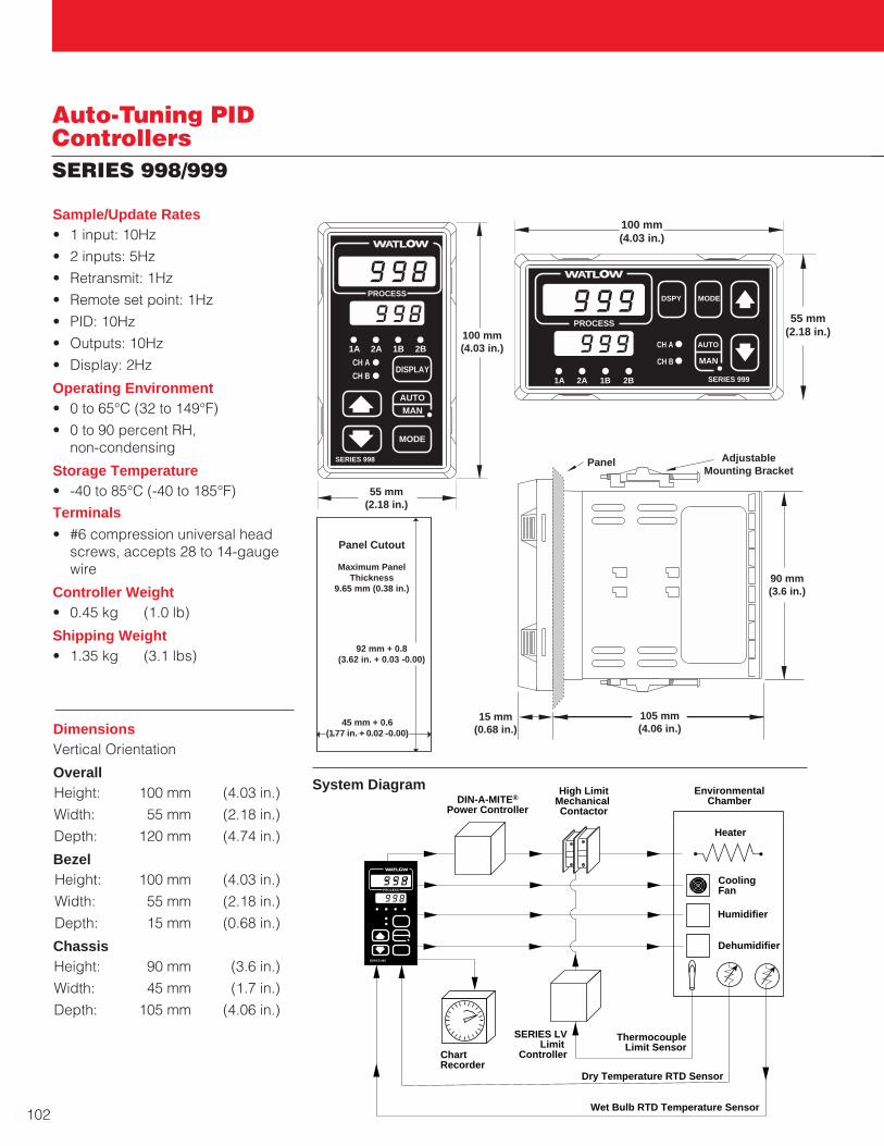
Auto-Tuning PIDControllersSERIES 998/999
DimensionsVertical Orientation
OverallHeight: 100 mm (4.03 in.)
Width: 55 mm (2.18 in.)
Depth: 120 mm (4.74 in.)
BezelHeight: 100 mm (4.03 in.)
Width: 55 mm (2.18 in.)
Depth: 15 mm (0.68 in.)
ChassisHeight: 90 mm (3.6 in.)
Width: 45 mm (1.7 in.)
Depth: 105 mm (4.06 in.)
Panel AdjustableMounting Bracket
105 mm(4.06 in.)
15 mm(0.68 in.)
90 mm(3.6 in.)
100 mm(4.03 in.)
55 mm(2.18 in.)
TLTL WWA
PROCESS
1A 2A 1B 2B
CH A
CH BDISPLAY
SERIES 998
MODE
AUTOMAN
High LimitMechanical Contactor
ThermocoupleLimit Sensor
Wet Bulb RTD Temperature Sensor
SERIES LVLimit
Controller
DIN-A-MITE®
Power Controller
Heater
TL WWA
PROCESS
SERIES 982
ChartRecorder
Cooling Fan
Humidifier
Dehumidifier
EnvironmentalChamber
Dry Temperature RTD Sensor
Panel Cutout
Maximum PanelThickness
9.65 mm (0.38 in.)
92 mm + 0.8(3.62 in. + 0.03 -0.00)
45 mm + 0.6(1.77 in. + 0.02 -0.00)
System Diagram
100 mm(4.03 in.)
55 mm(2.18 in.)
TLTL WWA
PROCESS
1A 2A 1B 2B
CH A
CH B
MODE
SERIES 999
DSPY
AUTO
MAN
Sample/Update Rates• 1 input: 10Hz
• 2 inputs: 5Hz
• Retransmit: 1Hz
• Remote set point: 1Hz
• PID: 10Hz
• Outputs: 10Hz
• Display: 2Hz
Operating Environment• 0 to 65°C (32 to 149°F)
• 0 to 90 percent RH, non-condensing
Storage Temperature• -40 to 85°C (-40 to 185°F)
Terminals
• #6 compression universal headscrews, accepts 28 to 14-gaugewire
Controller Weight• 0.45 kg (1.0 lb)
Shipping Weight• 1.35 kg (3.1 lbs)
102

W A T L O W
103
Mu
lti-Lo
op
A
uto
-Tu
nin
g P
ID
Auto-Tuning PIDControllersSERIES PDDual Loop
Watlow’s SERIES PD controllersutilize embedded Ethernettechnology to provide a convenient,economical means for setting up andviewing key process variables suchas temperature, pressure andhumidity. Available in single or dualchannel versions, the DIN-rail mountSERIES PD controllers offer up to fourcontrol/alarm outputs, as well as adigital/current transformer inputassociated with each channel.
Watlow’s SERIES PD controllers areideally suited for a wide range oftemperature or process controlapplications where the operatorinterface is supported from a remotelocation. The SERIES PD providesinterfacing via embedded firmwarewhich serves dedicated web pages.These pages support key functionsincluding operation, alarmmonitoring, configuration and aredisplayed using standard webbrowser software. The SERIES PD isalso capable of generating e-mailmessages for remote alarmnotification.
Ethernet-based products are rapidlygaining popularity in industrialapplications because they allow aninstantaneous exchange ofinformation between processingequipment and the company’smanagement system.
Advanced features of the SERIES PDcontrollers include internal datalogging of key control parameters,smart sensor technology, heater burnout detection and an enhanced control algorithm.
The SERIES PD controller is backedby a three-year warranty from WatlowWinona and is UL® 508, C-UL®, CSAand CE approved.
Features and Benefits
Ethernet connectivity
• Convenient, easy to use operatorinterface
• Simplified process monitoring
DIN-rail sub panel mounting
• Quick, economic installation
PDPID Controller
Power
Ethernet Link
Ethernet Activity
1
2
3
4
1
2
Input Error
Input Error
Output
Output
Output
OutputAddress
2 UniversalAnalog Inputs(Dual Channel)
4 outputs can beconfigured as control or event(alarm) outputs. Any output can be assignedto either channel 1 or 2.
Ethernet Communications
Event orCurrentTransformer(CT) Inputs
Watlow INFOSENSE™ sensortechnology
• INFOSENSE™ technologyimproves sensor accuracy by aminimum of 50 percent
Advanced control algorithm
• Tighter process control
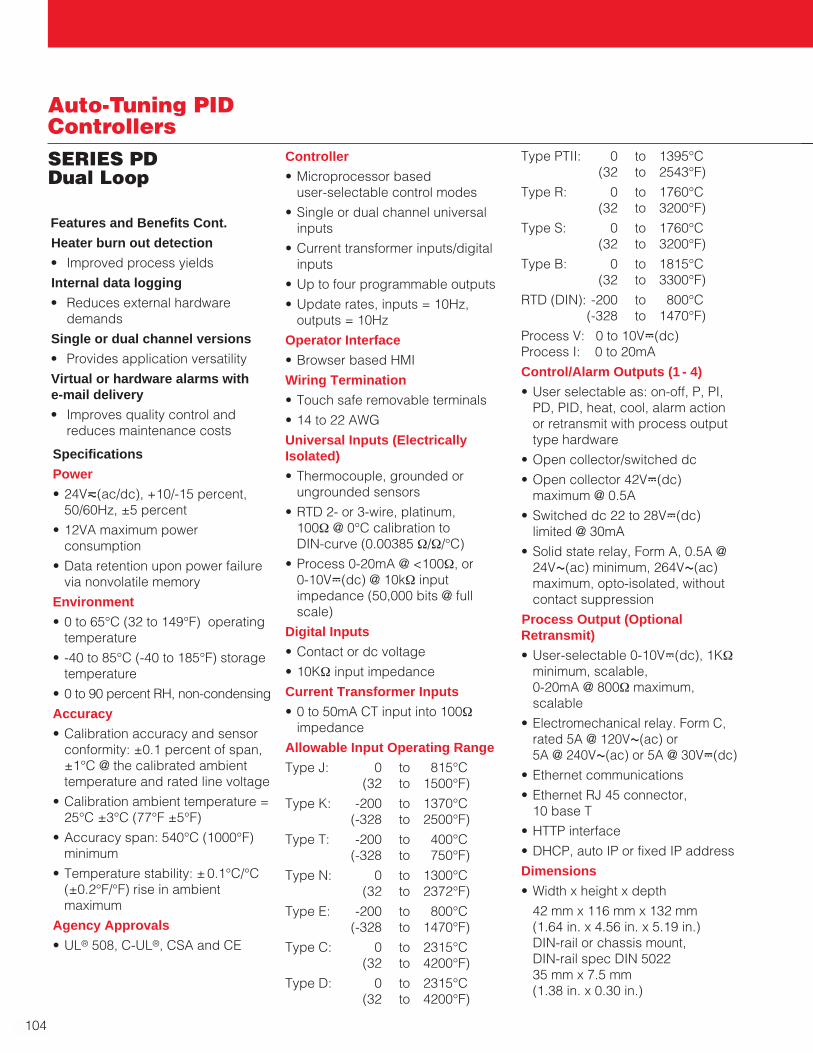
104
Auto-Tuning PIDControllersSERIES PDDual Loop
Type PTII: 0 to 1395°C(32 to 2543°F)
Type R: 0 to 1760°C(32 to 3200°F)
Type S: 0 to 1760°C(32 to 3200°F)
Type B: 0 to 1815°C(32 to 3300°F)
RTD (DIN): -200 to 800°C(-328 to 1470°F)
Process V: 0 to 10VÎ(dc)Process I: 0 to 20mA
Control/Alarm Outputs (1 - 4)
• User selectable as: on-off, P, PI,PD, PID, heat, cool, alarm actionor retransmit with process outputtype hardware
• Open collector/switched dc
• Open collector 42VÎ(dc)maximum @ 0.5A
• Switched dc 22 to 28VÎ(dc)limited @ 30mA
• Solid state relay, Form A, 0.5A @24VÅ(ac) minimum, 264VÅ(ac)maximum, opto-isolated, withoutcontact suppression
Process Output (OptionalRetransmit)
• User-selectable 0-10VÎ(dc), 1KΩminimum, scalable, 0-20mA @ 800Ω maximum,scalable
• Electromechanical relay. Form C,rated 5A @ 120VÅ(ac) or 5A @ 240VÅ(ac) or 5A @ 30VÎ(dc)
• Ethernet communications
• Ethernet RJ 45 connector, 10 base T
• HTTP interface
• DHCP, auto IP or fixed IP address
Dimensions
• Width x height x depth
42 mm x 116 mm x 132 mm (1.64 in. x 4.56 in. x 5.19 in.) DIN-rail or chassis mount, DIN-rail spec DIN 5022 35 mm x 7.5 mm (1.38 in. x 0.30 in.)
Specifications
Power
• 24Vı(ac/dc), +10/-15 percent,50/60Hz, ±5 percent
• 12VA maximum powerconsumption
• Data retention upon power failurevia nonvolatile memory
Environment
• 0 to 65°C (32 to 149°F) operatingtemperature
• -40 to 85°C (-40 to 185°F) storagetemperature
• 0 to 90 percent RH, non-condensing
Accuracy
• Calibration accuracy and sensorconformity: ±0.1 percent of span,±1°C @ the calibrated ambienttemperature and rated line voltage
• Calibration ambient temperature =25°C ±3°C (77°F ±5°F)
• Accuracy span: 540°C (1000°F)minimum
• Temperature stability: ±0.1°C/°C(±0.2°F/°F) rise in ambientmaximum
Agency Approvals
• UL® 508, C-UL®, CSA and CE
Controller
• Microprocessor based user-selectable control modes
• Single or dual channel universalinputs
• Current transformer inputs/digitalinputs
• Up to four programmable outputs
• Update rates, inputs = 10Hz,outputs = 10Hz
Operator Interface
• Browser based HMI
Wiring Termination
• Touch safe removable terminals
• 14 to 22 AWG
Universal Inputs (ElectricallyIsolated)
• Thermocouple, grounded orungrounded sensors
• RTD 2- or 3-wire, platinum, 100Ω @ 0°C calibration to DIN-curve (0.00385 Ω/Ω/°C)
• Process 0-20mA @ <100Ω, or 0-10VÎ(dc) @ 10kΩ inputimpedance (50,000 bits @ fullscale)
Digital Inputs
• Contact or dc voltage
• 10KΩ input impedance
Current Transformer Inputs
• 0 to 50mA CT input into 100Ωimpedance
Allowable Input Operating Range
Type J: 0 to 815°C(32 to 1500°F)
Type K: -200 to 1370°C(-328 to 2500°F)
Type T: -200 to 400°C(-328 to 750°F)
Type N: 0 to 1300°C(32 to 2372°F)
Type E: -200 to 800°C(-328 to 1470°F)
Type C: 0 to 2315°C(32 to 4200°F)
Type D: 0 to 2315°C(32 to 4200°F)
Features and Benefits Cont.
Heater burn out detection
• Improved process yields
Internal data logging
• Reduces external hardwaredemands
Single or dual channel versions
• Provides application versatility
Virtual or hardware alarms with e-mail delivery
• Improves quality control andreduces maintenance costs

W A T L O W
105
SERIES PDDual Loop
Auto-Tuning PIDControllers
DIN-rail
146 mm(3.750 in.)
73 mm(2.875 in.)
129 mm(5.062 in.)
Attachment Angle 10
DIN-rail
Bracket for Panel Mounting
(#6 Screwor m3.5 Required)
8 mm(0.318 in.)
107 mm(4.225 in.)
118 mm(4.650 in.)
Min. Clearance 51 mm(2 in.)
Min. ClearanceBetween RailCenterlines
146 mm(5.750 in.)
42 mm(1.637 in.)
42 mm(1.650 in.)
Top/BottomMountHole Offset
PDPID Controller
Power
Ethernet Link
Ethernet Activity
1
1
2
Input Error
Input Error
Output
Output
Output
OutputAddress
PDPID Controller
Power
Ethernet Link
Ethernet Activity
1
2
3
4
1
2
Input Error
Input Error
Output
Output
Output
OutputAddress
PDPID Controller
Power
Ethernet Link
Ethernet Activity
1
2
3
4
1
2
Input Error
Input Error
Output
Output
Output
OutputAddress
4
3
2
Side View Front View
Mu
lti-Lo
op
A
uto
-Tu
nin
g P
ID

Ordering Information
To order, complete the code number on the right with the information below.
P D D _ - _ _ _ _ - _ A _ _
Auxiliary Inputs
1 = Dual digital inputs2 = One CT input and one digital input3 = Dual CT inputs (dual channel only)Output 1
C = Switched dc, open collectorK = SSR, Form A, 0.5AF = Universal processE = Mechanical relay, Form C, 2Aa
Output 2
A = NoneC = Switched dc, open collectorK = SSR, Form A, 0.5AE = Mechanical relay, Form C, 2Aa
Output 3A = NoneC = Switched dc, open collectorK = SSR, Form A, 0.5AF = Universal processE = Mechanical relay, Form C, 2Aa
Output 4
A = NoneC = Switched dc, open collectorK = SSR, Form A, 0.5AE = Mechanical relay, Form C, 2Aa
On Board Data Logging
0 = NoneK = 16 megabytes of memoryCustom Options
AA = Watlow logo BB = No logo
106
Auto-Tuning PIDControllersSERIES PDDual Loop
F.O.B.: Winona, Minnesota
a Electromechanical relays warranted for 100,000closures only. Solid state switching devicesrecommended for applications requiring fast cycletimes or extended service life.
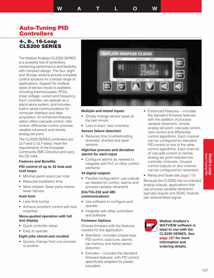
W A T L O W
Auto-Tuning PIDControllers4-, 8-, 16-LoopCLS200 SERIES
The Watlow Anafaze CLS200 SERIESis a powerful line of controllers,combining performance and flexibilitywith compact design. The four, eightand 16-loop versions provide completecontrol solutions for a broad range ofapplications. Support for multipletypes of sensor inputs is available,including thermocouples, RTDs,linear voltage, current and frequency.Each controller can operate as astand-alone system, and includesbuilt-in serial communications for computer interface and dataacquisition. An enhanced featuresoption offers cascade control, ratiocontrol, differential control, processvariable retransmit and remoteanalog set point.
The CLS200 SERIES controllers areUL® and C-UL® listed, meet therequirements of the EuropeanCommunity EMC Directive and carrythe CE mark.
Features and Benefits
PID control of up to 16 heat andcool loops
• Minimal panel space per loop
• Reduced installation time
• More reliable: fewer parts meansfewer failures
Auto-tune
• Less time tuning
• Achieve excellent control with lessexpertise
Menu-guided operation with fulltext display
• Quick controller setup
• Easy to operate
Eight jobs stored and recalled
• Quickly change from one processto another
Multiple and mixed inputs
• Simply change sensor types atthe last minute
• Less to learn, less inventory
Sensor failure detection
• Reduces time troubleshootingreversed, shorted and opensensors
High/low process and deviationalarms for each input
• Configure alarms as needed tointegrate with PLC or other controlelements
34 digital outputs
• Flexible configuration: use outputsas needed for control, alarms andprocess variable retransmit
EIA/TIA-232 and 485communications
• Use software to configure andoperate
• Integrate with other controllersand software
Firmware Options
Choose firmware with the featuresneeded for the application:
• Standard—includes closed-loopPID control, auto-tune, alarms, job memory and failed sensordetection
• Extruder— includes the standardfirmware features, with PID controlspecifically adapted for plasticextruders
Watlow Anafaze’sWATVIEW software isideal to use with theCLS200 SERIES. Seepage 197 for moreinformation andordering details.
• Enhanced Features— includesthe standard firmware featureswith the addition of processvariable retransmit, remoteanalog set point, cascade control,ratio control and differentialcontrol algorithms. Each channelcan be configured for standardPID control or one of the other control algorithms. Each channelof cascade control or remoteanalog set point requires twocontroller channels. Unusedcontrol outputs on any channelcan be configured for retransmit.
• Ramp and Soak see page 119
Because the CLS200 has no onboardanalog outputs, applications thatuse process variable retransmittypically require one SDAC moduleper retransmitted signal.
107
Mu
lti-Lo
op
A
uto
-Tu
nin
g P
ID
108
Auto-Tuning PIDControllers4-, 8-, 16-LoopCLS200 SERIES
Specifications
Operator Interface
• 32-character vacuum fluorescentdisplay
• Eight-key keypad to accessguided menus and prompts, enter passkey sequence, setvalues, switch between single channel and multiplechannel displays
• Controller configuration can beloaded through the standardserial port
Analog Inputs
• CLS204 4 Differential
• CLS208 8 Differential
• CLS216 16 Single-ended
Noise Rejection
• 120db at 60Hz
Temperature Coefficient
• 40 ppm/˚C
Sensors/Inputs
• Thermocouples: User-selectabletype, direct connection,linearization, reference junctioncompensation, reversed andshorted T/C detection andupscale break protection withoutput averaging
• RTD: (CLS204 and CLS208 only)2- or 3-wire, platinum, 100Ω @ 0˚C,DIN 0.003850Ω/˚C curve. Twouser-selectable ranges offerdifferent resolutions. Requiresscaling resistors. See Special/Linear Inputs in OrderingInformation
• Linear: current and voltagesignals from linear transmitters
• Pulse input
Input Range and Accuracy Range Accuracy
Type B 66 to 1760°C ±4.0°C
(150 to 3200°F) (±7.2°F)
Type E -200 to 787°C ±1.0°C
(-328 to 1448°F) (±1.8°F)
Type J -212 to 760°C ±1.2°C
(-350 to 1400°F) (±2.2°F)
Type K -268 to 1371°C ±1.3°C
(-450 to 2500°F) (±2.3°F)
Type R -18 to 1766°C ±2.8°C
(0 to 3210°F) (±5.0°F)
Type S -18 to 1760°C ±2.8°C
(0 to 3200°F) (±5.0°F)
Type T -268 to 399°C ±1.6°C
(-450 to 750°F) (±2.9°F)
RTD’s available on CLS204 andCLS208 only
Range Accuracy
(RTD1) -100 to 275°C 1.1°C(-148 to 527°F) (2.0°F)
(RTD2) -120 to 840°C 1.6°C(-184 to 1544°F) (2.9°F)
Note: Accuracy @ 25˚C (77°F)ambient. Valid for 10 to 100 percentof span except Type B, which isspecified for 427°C to 1760°C (800˚F to 3200˚F.) RTD is for 100percent of span
Linear Voltage and Current Inputs
Requires scaling resistors. See Special Inputs in OrderingInformation
0-10mAÎ(dc)
0-20mAÎ(dc)/4-20mAÎ(dc)
0-100mVÎ(dc)
0-500mVÎ(dc)
0-1VÎ(dc)
0-5VÎ(dc)
0-10VÎ(dc)
0-12VÎ(dc)
Other ranges available. Consultfactory
Pulse Input
• One TTL-level square wave inputup to 2kHz
Input Sampling Rate @ 60Hz
Each channel has the followingscans per second:
• CLS204: 6 samples per second,(update time: 0.167 sec.)
• CLS208: 3 samples per second,(update time: 0.333 sec.)
• CLS216: 1.5 samples per second,(update time: 0.667 sec.)
Internal Measurement Resolution
• 0.006 percent, greater than 14 bits
Calibration
• Automatic zero and full scale
Digital Inputs
• TTL-level used for selectingrecipes or jobs or R/S triggers
• Eight inputs and one pulse inputwith 50-pin terminal board option
• Two inputs and pulse input orthree inputs with 18-pin terminalblock option
Digital Outputs
• 34 digital outputs are availablewith 50-pin terminal board option
• 10 control outputs with 18-pinterminal block option
• One or two control outputs areuser assigned for each loop
• Each control output can beconfigured for on-off time proportioning, or distributed zerocrossing
• Outputs sink up to 60mA each at5VÎ(dc)
• 350mA at 5VÎ(dc) available fromon-board supply
Analog Outputs
• Use DAC and SDAC accessorymodules. For process variableretransmit, use SDAC only. See page 159.

W A T L O W
Auto-Tuning PIDControllers4-, 8-, 16-LoopCLS200 SERIES
Alarm Outputs
• Independent process anddeviation alarms for each channel
• Alarms can operate any output notused for control
• User-programmable deadband,delay and startup suppression
• Global alarm output activateswhen any alarm occurs
• Watchdog output indicatescontroller is functioning correctly
Overall
Height: 50 mm (1.96 in.)
Width: 96 mm (3.78 in.)
Depth 203 mm (8.0 in.)
Bezel
Height: 50 mm (1.96 in.)
Width: 96 mm (3.78 in.)
Depth 25 mm (1.0 in.)
Chassis
Height: 45 mm (1.76 in.)
Width: 90 mm (3.55 in.)
Depth 178 mm (7.0 in.)
Dimensions
Serial Interface
• EIA/TIA-232 or EIA/TIA-485
Baud Rate
• 2400, 9600 or 19200, user-selectable
Communication Protocol
• Modbus™ RTU
Line Voltage/Power
• 15 to 24VÎ(dc) ± 3VÎ(dc) @ 1A(maximum), 300mA (no load)
Agency Approvals
• UL®, C-UL® listed: UL® 916,Standard for Energy Management Equipment
• CE Mark: ElectromagneticCompatibility (EMC) Directive89/336/EEC
YESCHNG
SP
RAMP SOAK
ALARMACK
NOMANAUTO
PROCESSLOOP
ALARM STATUS OUT%SETPOINT
UNITS
BACK ENTER
50 mm (1.96 in.)
96 mm (3.78 in.)
(1.00 in.) (7.00 in.) (1.60 in.)25 mm 178 mm 41 mm*
Bezel Steel Case
Terminals
SCSI Cable(not used with TB-18)
*15 mm (0.6 in.) with Right Angle SCSI Connector
Controller Weight
0.9 kg (1.98 lbs)
Shipping Weight
1.8 kg (4.0 lbs)
Modbus™ is a trademark ofAEG Schneider Automation. 109
Mu
lti-Lo
op
A
uto
-Tu
nin
g P
ID

110
Auto-Tuning PIDControllers4-, 8-, 16-LoopCLS200 SERIES
Ordering InformationTo order, complete the code number to the right with the information below:
2 _ _ - _ _ _ _ _ _ _Number of Channels
04 = 4 channel08 = 8 channel16 = 16 channel Controller Type
1 = Standard EPROM2 = Extruder 3 = Ramp and soak4 = Enhanced featuresTerminal Block
0 = No terminal block accessory1 = 18-pin terminal block (CLS204 and CLS208 only)2 = 50-pin terminal block installed (includes 3 foot SCSI cable)Power Supply
0 = No power supply2 = 120/240VÅ(ac), 50/60Hz power supply adapter
(5VÎ[dc], @ 4A, 15VÎ[dc] @ 1.2A) (CE approved)SCSI Cables
0 = No SCSI cable (3 foot cable included with 50-pin terminal block)1 = 6 foot SCSI cable2 = 3 foot right angle SCSI cable3 = 6 foot right angle SCSI cableSerial Communication Cables
0 = No serial communications cable1 = 10 foot serial communications cable (DB-9 female/bare wire)2 = 25 foot serial communications cable (DB-9 female/bare wire)3 = 50 foot serial communications cable (DB-9 female/bare wire)Serial Communication Jumper Settings
0 = EIA/TIA-2321 = EIA/TIA-4852 = EIA/TIA-485 terminatedSpecial Inputs(Standard unit is configured for thermocouples and -10 to 60 mV linear inputs. For other sensors,order special inputs. See below for ordering instructions. For CLS216 specify two digits, forCLS204 and CLS208 specify one digit.)
0 or 00 = Thermocouples and -10 to 60 mV inputs onlyX or XX = Number of current, voltage or RTD inputs
C L S S I _ _ - _ _ - _ _Special/Linear Input Type
(Not required for thermocouple sensor inputs.)20 = RTD 1: 0.1°, -100.0 to 275.0°C (-148.0 to 527.0°F)
Not available on CLS21621 = RTD 2: 1°, -120 to 840°C (-184 to 1544°F)
Not available on CLS21643 = 0-10mAÎ(dc)44 = 0-20mAÎ(dc)/4-20mAÎ(dc)50 = 0-100mVÎ(dc)52 = 0-500mVÎ(dc)53 = 0-1VÎ(dc)55 = 0-5VÎ(dc)56 = 0-10VÎ(dc)57 = 0-12VÎ(dc)Start Channel
XX = Channel number XXEnd Channel
XX = Channel number XX
AvailabilityUp to four weeks, depending oncomplexity and order releasequantity. Consult factory for details
Note: Controller is configured forthermocouples and -10 to 60mVÎ(dc)linear inputs. For other sensors orderspecial inputs, see below. For analogoutputs order DAC or SDAC modules,see page 159. For easy setup orderWATVIEW software, see page 197.
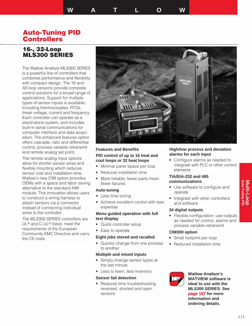
W A T L O W
111
Auto-Tuning PIDControllers16-, 32-Loop MLS300 SERIES
The Watlow Anafaze MLS300 SERIESis a powerful line of controllers thatcombines performance and flexibilitywith compact design. The 16 and 32-loop versions provide completecontrol solutions for a broad range ofapplications. Support for multipletypes of sensor inputs is available;including thermocouples, RTDs,linear voltage, current and frequency.Each controller can operate as astand-alone system, and includesbuilt-in serial communications forcomputer interface and data acqui-sition. The enhanced features optionoffers cascade, ratio and differentialcontrol, process variable retransmitand remote analog set point.
The remote analog input optionsallow for shorter sensor wires andflexible mounting which reducessensor cost and installation time.Watlow’s new CIM option providesOEMs with a space and labor savingalternative to the standard AIMmodule. This innovation allows usersto construct a wiring harness toattach sensors via a connectorinstead of connecting individualwires to the controller.
The MLS300 SERIES controllers areUL® and C-UL® listed, meet therequirements of the EuropeanCommunity EMC Directive and carrythe CE mark.
Features and Benefits
PID control of up to 16 heat andcool loops or 32 heat loops• Minimal panel space per loop
• Reduces installation time
• More reliable: fewer parts meanfewer failures
Auto-tuning• Less time tuning
• Achieve excellent control with lessexpertise
Menu guided operation with fulltext display• Quick controller setup
• Easy to operate
Eight jobs stored and recalled
• Quickly change from one process to another
Multiple and mixed inputs• Simply change sensor types at
the last minute
• Less to learn, less inventory
Sensor fail detection• Reduces time troubleshooting
reversed, shorted and opensensors
Watlow Anafaze’sWATVIEW software isideal to use with the MLS300 SERIES. Seepage 197 for moreinformation andordering details.
High/low process and deviationalarms for each input• Configure alarms as needed to
integrate with PLC or other controlelements
TIA/EIA-232 and 485communications• Use software to configure and
operate
• Integrate with other controllersand software
34 digital outputs• Flexible configuration: use outputs
as needed for control, alarms andprocess variable retransmit
CIM300 option• Small footprint per loop
• Reduced installation time
Mu
lti-Lo
op
A
uto
-Tu
nin
g P
ID

112
Auto-Tuning PIDControllers16-, 32-Loop MLS300 SERIES
Specifications
Operator Interface• 32-character vacuum fluorescent
display
• Eight-key keypad to accessguided menus and prompts, enterpasskey sequence, set values,switch between single channeland multiple channel displays
• Controller’s configuration can beloaded through the standardserial port
Analog Inputs• MLS316 16 Differential
• MLS332 32 Differential
Noise Rejection• 120dB at 60Hz
Temperature Coefficient• 40 ppm/°C
Temperature Sensors• Thermocouples: User selectable
type, direct connection, linearization, reference junctioncompensation, reversed andshorted T/C detection andupscale break protection withoutput averaging
• RTD: 2- or 3-wire, platinum, 100Ω@ 0°C, DIN 0.003850Ω/°C curve. Two user-selectable ranges offerdifferent resolutions. Requiresspecial inputs. See OrderingInformation
Input Range and AccuracyRange Accuracy
Type B 66 to 1760°C ±4.0°C(150 to 3200°F) (±7.2°F)
Type E -200 to 787°C ±1.0°C(-328 to 1448°F) (±1.8°F)
Type J -212 to 760°C ±1.2°C(-350 to 1400°F) (±2.2°F)
Type K -268 to 1371°C ±1.3°C(-450 to 2500°F) (±2.3°F)
Type R -18 to 1766°C ±2.8°C(0 to 3210°F) (±5.0°F)
Type S -18 to 1760°C ±2.8°C(0 to 3200°F) (±5.0°F)
Type T -268 to 399°C ±1.6°C(-450 to 750°F) (±2.9°F)
RTD1 (DIN)-100 to 275°C ±1.1°C(-148 to 527°F) (±2.0°F)
RTD2 (DIN)-120 to 840°C ±1.6°C(-184 to 1544°F) (±2.9°F)
Note: Accuracy @ 25°C (77°F)ambient. Valid for 10 to 100 percentof span except Type B, which isspecified for 427°C (800°F) to1760°C (3200°F). RTD is for 100percent of spanLinear Voltage and Current Inputs
Requires special inputs. See Ordering Information
0-10mAÎ(dc)
0-20mAÎ(dc)/4-20mAÎ(dc)
0-100mVÎ(dc)
0-500mVÎ(dc)
0-1VÎ(dc)
0-5VÎ(dc)
0-10VÎ(dc)
0-12VÎ(dc)
Other ranges available. Consultfactory
Pulse Input
One TTL-level square wave input upto 2kHz
Input Sampling Rate @ 60Hz
Each channel has the followingscans per second:• MLS316: 1.5 samples per
second, (update time: 0.667 sec.)
• MLS332: 0.75 samples persecond, (update time: 1.33 sec.)
Internal Measurement Resolution• 0.006 percent, greater than
14 bits
Calibration• Automatic zero and full scale
Digital Inputs• TTL level used for selecting
recipes or jobs, or R/S triggers
• Eight inputs and one pulse inputwith 50-pin terminal board option
Digital Outputs• 34 outputs available with 50-pin
terminal board option
• One or two control outputs areuser assigned for each loop
• Each control output can beconfigured for on-off, time proportioning, or distributed zerocrossing
• Outputs sink up to 60mA each at5VÎ(dc)
Alarm Outputs• Independent process and
deviation alarms for each channel
• Alarms can operate any outputnot used for control
• Programmable deadband, delayand startup suppression
• Global alarm output activateswhen any alarm occurs
• Watchdog output indicatescontroller is functioning correctly
Analog Outputs• Use DAC and SDAC accessory
modules. For process variableretransmit, use SDAC only, seepage 159.

W A T L O W
113
Auto-Tuning PIDControllers16-, 32-Loop MLS300 SERIES
Specifications Cont.
Serial Interface• EIA/TIA-232 or EIA/TIA-485
Baud Rate• 2400, 9600 or 19200,
user-selectable
Communication Protocol• Modbus™ RTU
Line Voltage/Power• 15 to 24VÎ(dc) ± 3VÎ(dc) @ 1A
Agency Approvals• UL®, C-UL® Listed: UL® 916,
Standard for Energy ManagementEquipment
• CE Mark: ElectromagneticCompatibility (EMC) Directive89/336/EEC
Firmware Options
Choose firmware with the featuresneeded for the application:• Standard—includes closed-loop
PID control, auto-tune, alarms, jobmemory and failed sensordetection
• Extruder— includes the standardfirmware features, with PID controlspecifically adapted for plasticextruders
• Enhanced Features— includesthe standard firmware featureswith the addition of processvariable retransmit, remote analogset point, cascade control, ratiocontrol and differential controlalgorithms. Each channel can beconfigured for standard PIDcontrol or one of the other controlalgorithms. Each channel ofcascade control or remote analogset point requires two controllerchannels. Unused control outputson any channel can beconfigured for retransmit
• Ramp and soak see page 123
Input Module Options
Choose the input moduleappropriate for the application:
• AIM316 and AIM332 provides screw terminations for 16 or 32sensors
• CIM316 and CIM332 provides DB-50 connector terminations for16 or 32 sensors in a compact size
YESCHNG
SP
RAMPSOAK
ALARMACK
NOMANAUTO
PROCESSLOOP
ALARM STATUS
UNITS
BACK ENTER
SETPOINT OUT%
25 mm(1.00 in.)
188 mm(7.40 in.)
41 mm*(1.60 in.)
50 mm(1.96 in.)
Processor Module (Side)
*15 mm (0.60 in.) with Right Angle SCSI Connector
Processor Module (Front)
50 mm(1.96 in.)
96 mm(3.78 in.)
Mu
lti-Lo
op
A
uto
-Tu
nin
g P
ID

114
Auto-Tuning PIDControllers16-, 32-Loop MLS300 SERIES
Ordering Information
To order, complete the code number to the right with the information below:3 _ _ - _ _ _ _ _ _ _ _ _
Input Module16 = 16 channel analog input module (AIM316)32 = 32 channel analog input module (AIM332)C1 = 16 channel compact input module (CIM316)C2 = 32 channel compact input module (CIM332)Processor Module (MLS300-PM)0 = Input module only (No MLS300-PM)1 = MLS300-PM with standard firmware2 = MLS300-PM with extruder firmware3 = MLS300-PM with enhanced features firmware4 = MLS300-PM with ramp and soak firmwareTerminal Block0 = No terminal block accessory1 = 50-pin terminal block, includes 3 foot SCSI cablePower Supply0 = None2 = 120/240VÅ(ac) 50/60Hz power supply adapter
[5VÎ(dc) @ 4A, 15VÎ(dc) @ 1.2A] CE approved SCSI Cables (For use with 50-pin terminal board)0 = No special SCSI cable (3 foot cable is included with 50-pin terminal board)1 = 6 foot SCSI cable2 = 3 foot right angle SCSI cable3 = 6 foot right angle SCSI cable Serial Communication Cables (For communications with computer)0 = No serial communications cable1 = 10 foot EIA/TIA-232 comm. cable, DB-9 female/RJ12 phone plug 2 = 25 foot EIA/TIA-232 comm. cable, DB-9 female/RJ12 phone plug 3 = 50 foot EIA/TIA-232 comm. cable, DB-9 female/RJ12 phone plug 7 = EIA/TIA-485 terminal block with 2 foot cable8 = EIA/TIA-485 terminal block with 4 foot cableModule Interconnect Cables0 = No special cable (4 foot cable comes with input module)1 = 10 foot cable, RJ45 connector/RJ45 connector2 = 25 foot cable, RJ45 connector/RJ45 connectorSerial Communication Jumper0 = EIA/TIA-2321 = EIA/TIA-4852 = EIA/TIA-485 terminated Special Inputs(Standard unit is configured for thermocouples and -10 to 60 mV linear inputs. For other sensors, order special inputs.)00 = Thermocouples and -10 to 60 mV inputs onlyXX = Number of current, voltage, or RTD inputs. Include leading zero as needed
M L S 3 0 0 S I _ _ - _ _ - _ _Special Input Type20 = RTD 1: 0.1° Platinum, -100 to 275°C (-148 to 527°F)21 = RTD 2: 1° Platinum, -120 to 840°C (-184 to 1544°F)43 = 0-10mAÎ(dc)44 = 0-20mAÎ(dc)/4-20mAÎ(dc)50 = 0-100mVÎ(dc)52 = 0-500mVÎ(dc)53 = 0-1VÎ(dc)55 = 0-5VÎ(dc)56 = 0-10VÎ(dc)57 = 0-12VÎ(dc)Start ChannelXX = Channel number XXEnd ChannelXX = Channel number XX
AvailabilityUp to four weeks depending oncomplexity and order releasequantity. Consult factory for details
F.O.B.: Winona, Minnesota
Analog Input Module(AIM332 shown)
146 mm H(5.75 in.)
165 mm L(6.5 in.) W
127 mm (5.0 in.)
Compact Input Module(CIM332 shown)
191 mm(7.50 in.)
70 mm(2.75 in.)
95 mm(3.75 in.)

W A T L O W
115
SERIES D8
Auto-Tuning PIDControllers
The Watlow Anafaze SERIES D8 is a powerful line of controllers thatcombines performance and flexibilitywith compact design. Compliancewith the ODVA and SemiconductorSIG standards means this controlleris easy to integrate into systems withDeviceNet™ networks on CAN(Controller Area Network).
The four and eight loop versions ofSERIES D8 controllers providecomplete control solutions for abroad range of applications.Support for multiple types of sensorinputs including thermocouples,RTDs, linear voltage and current is also available.
Each loop can be individuallyconfigured for on-off control or PIDcontrol. Loops can be combined toachieve cascade, ratio or differentialcontrol. Process variable retransmitand remote analog set point areincluded.
The SERIES D8 controllers are UL®
and C-UL® listed, meet therequirements of the EuropeanCommunity EMC Directive and carrythe CE mark.
Features and Benefits
PID control of up to eight loops• Minimal panel space per loop
• Reduced installation time
• More reliable: fewer parts meanfewer failures
Complies with ODVA (OpenDeviceNet™ Vendors Association)and Semiconductor SIG (SpecialInterest Group) specifications forDeviceNet™ on CAN (ControllerArea Network)• Integrates with other DeviceNet™
nodes and software
• Sealed micro connector minimizesinstallation time and footprint whilemaximizing reliability
• Rotary baud rate and nodeaddress switches simplify setup
• Network and module status LEDssimplify commissioning andtroubleshooting a network
Flexible, easy-to-use interface• Easy set up with menu guided,
full-text prompts
• Context-sensitive, on-screen helpsaves time
Advanced control utilities• Auto-tune optimizes control with
minimal effort and expertise
• Cascade minimizes overshootand improves control in systemswith excessive thermal lag
• Ratio and differential enhancecontrol in areas where therelationship between two or moreloops is paramount
Specifications
Operator Interface• 32-character vacuum fluorescent
display
• Eight-key keypad to accessguided menus and prompts, setvalues and view channel displays
• Built-in context sensitive help
Noise Rejection• 120dB at 60Hz
Temperature Coefficient• 40ppm/˚C
Analog Inputs• Thermocouples: User selectable
type, direct connection,linearization, reference junctioncompensation, reversed andshorted T/C detection andupscale break protection withoutput averaging.
• RTD: 2- or 3-wire, platinum, 100Ω @ 0˚C, DIN-curve. Requiresscaling resistors. See specialinputs in ordering information
• Linear: current and voltagesignals from linear transmitter
DeviceNet™ is a trademark of the Open DeviceNetVendors Association.
Mu
lti-Lo
op
A
uto
-Tu
nin
g P
ID

Auto-Tuning PIDControllers
Specifications Cont.Input Range and Accuracy
Range Accuracy
Type B 66 to 1760°C ±4.0°C(150 to 3200°F) (±7.2°F)
Type E -200 to 787°C ±1.0°C(-328 to 1448°F) (±1.8°F)
Type J -212 to 760°C ±1.2°C(-350 to 1400°F) (±2.2°F)
Type K -268 to 1371°C ±1.3°C(-450 to 2500°F) (±2.4°F)
Type R -18 to 1766°C ±2.8°C(0 to 3210°F) (±5.0°F)
Type S -18 to 1760°C ±2.8°C(0 to 3200°F) (±5.0°F)
Type T -268 to 399°C ±1.6°C(-450 to 750°F) (±2.9°F)
RTD (DIN)-200.0 to 621.0°C ±0.5°C(-328.0 to1150.0°F) (±0.9°F)
Note: Accuracy @ 25°C (77°F)ambient. Valid for 10 to 100 percentof span except Type B, which isspecified for 427°C (800°F) to1760°C (3200°F). RTD is for 100percent of spanLinear Voltage and Current Inputs
Requires scaling resistors. See special inputs in OrderingInformation
0-10mAÎ(dc)
0-20mAÎ(dc)/4-20mAÎ(dc)
0-100mVÎ(dc)
0-500mVÎ(dc)
0-1VÎ(dc)
0-5VÎ(dc)
0-10VÎ(dc)
0-12VÎ(dc)
Other ranges available. Consultfactory
Input Sampling Rate @ 60Hz
Each channel has the followingscans per second:• D84: Six samples per second,
(update time: 0.167 sec.)
• D88: Three samples per second,(update time: 0.333 sec.)
Internal Measurement Resolution• 0.006 percent, greater than
14 bits
Calibration• Automatic zero and full scale
Digital Inputs• TTL level used for logic, remote
alarm acknowledge, selectingrecipes or jobs
• Eight inputs with 50-pin terminalboard option
• Three inputs with 18-pin terminalblock option
Digital Outputs• 18 digital outputs available with a
50-pin terminal board option
• 11 outputs available with 18-pinterminal block option
• One or two control outputs areuser assigned for each loop
• Each control output can beconfigured for on-off, time proportioning, or distributed zerocrossing
• Outputs sink up to 60mA each at5VÎ(dc)
Alarm Outputs• Independent process and
deviation alarms for each channel
• Alarms can operate any outputnot used for control
• User programmable deadband,delay and startup suppression
• Global alarm output activateswhen any alarm occurs
• Watchdog output indicatescontroller is functioning correctly
Analog Outputs• Use DAC and SDAC accessory
modules. See page 159.
SERIES D8 DeviceNet™ Interface• Fully compliant with the interface
guidelines for DeviceNet™ onsemiconductor manufacturing tools
• Supports predefined master/slaveconnection set
• Group two only slave device
• Module status and network statusLEDs
• Rotary baud rate and nodeaddress switches
• Hardware and software selectablebaud rates: 125K, 250K and 500K
• Hardware and software selectablenode address: 0 to 63
• Supports polled I/O and explicitmessaging connections
• Polled I/O response: less than 1millisecond
• Explicit message response: lessthan 50 milliseconds
• EDS (Electronic Data Sheet)
• Connector: 5-pin, micro style,sealed, male
• Optically isolated CANBUSinterface
• Bus plugable while hot
• Bus miswire protection
Line Voltage/Power• 15 to 24VÎ(dc) ± 3VÎ(dc) @ 1A
(loaded) or 300mA (no load)
Agency Approvals• UL®, C-UL® Listed: UL® 916,
standard for energy managementequipment
• CE Mark: ElectromagneticCompatibility (EMC) Directive89/336/EEC
• ODVA conformance testedDeviceNet™
116

W A T L O W
Auto-Tuning PIDControllers
AddressData Rate
MSD LSD
2
6
4
0
P
2
6
40
8
PGM500 Kb250 Kb125 Kb
25 mm (1.0 in.)
41 mm to 53 mm(1.6 in. to 2.1 in.) For Cablesand Clearance
188 mm (7.4 in.)
Front View
Side View
96 mm (3.8 in.)
50 mm (2.0 in.)
D8 with TB18 Option for Digital I/O D8 with SCSI/TB50 Option for Digital I/O
Connect Digital I/O Here With TB18 Option SCSI Cable
TB50 Terminal Board Option: Digital I/O Connects Here
SERIES D8
117
Mu
lti-Lo
op
A
uto
-Tu
nin
g P
ID

Ordering Information
To order, complete the code number on the right with the information below.
D 8 _ 0 - 0 0 0 0 - _ _ 0 _
Number of Loops
4 = 4 loop controller8 = 8 loop controllerDigital I/O Terminations
0 = TB18 (Screw terminals on the controller)1 = SCSI connector, no terminal board or cable2 = SCSI connector, TB50 terminal board and 3-foot cable3 = SCSI connector, TB50 and 6-foot cable4 = SCSI connector, TB50 and 3-foot right angle cable5 = SCSI connector, TB50 and 6-foot right angle cablePower Supply
0 = No power supply1 = CE power supplySpecial Inputs0 = Thermocouples and -10 to 60 mV inputs onlyX = Number of current, voltage and RTD inputs
Special Inputs
Specify an input type for each channel or block of channels that needs factory installedresistors. Include a descriptor in the controller part description in the form specified below foreach special input type. Make sure the number of special inputs specified is equal to thenumber of special inputs in the controller part number
D 8 S I _ _ - _ _ - _ _Special Input Type(Not required for thermocouple sensor inputs)23 = RTD43 = 0-10mAÎ(dc)44 = 0-20mAÎ(dc)/4-20mAÎ(dc)50 = 0-100mVÎ(dc)52 = 0-500mVÎ(dc)53 = 0-1VÎ(dc)55 = 0-5VÎ(dc)56 = 0-10VÎ(dc)57 = 0-12VÎ(dc)Start ChannelXX = Channel Number XXEnd ChannelXX = Channel Number XX
Auto-Tuning PIDControllersSERIES D8
118
AvailabilityUp to four weeks, depending oncomplexity and order releasequantity. Consult factory for details
F.O.B.: Winona, Minnesota

Mu
lti-Lo
op
P
ID w
ith T
ime/T
emp
erature P
rofilin
gW A T L O W
PID with Time/TemperatureProfiling Controllers4-, 8-, 16-LoopCLS200 SERIES
The Watlow Anafaze CLS200 SERIESis a powerful line of controllers,combining performance and flexibilitywith compact design. The four, eight and 16 loop versions providecomplete control solutions for abroad range of applications. Supportfor multiple types of sensor inputs isavailable, including thermocouples,RTDs, linear voltage, current andfrequency. Each controller canoperate as a stand-alone system andincludes built-in serial communi-cations for computer interface anddata acquisition. Ramp and soakfeatures allow complex batchprocessing and sequencing. Up to17 ramp and soak profiles can beprogrammed with up to 20 stepseach. Individual loops can beconfigured for standard control orramp soak. Unused control outputscan be configured for events, alarmsand process variable retransmit.
The CLS200 SERIES controllers areUL® and C-UL® listed and meet therequirements of the EuropeanCommunity EMC Directive and carrythe CE mark.
Features and Benefits
Ramp and soak control of up to 16 heat and cool loops
• Minimal panel space per loop
• Reduces installation time
• More reliable: fewer parts meansfewer failures
Auto-tuning
• Less time tuning
• Achieve excellent control with lessexpertise
Menu-guided operation with fulltext display
• Setup controller quickly
• Easy to operate
Eight jobs stored and recalled
• Quick to change from oneprocess to another
Multiple and mixed inputs
• Easy to change sensor types atthe last minute
• Less to learn, less inventory
Sensor failure detection
• Reduces time troubleshootingreversed, shorted and open sensors
UL® and C-UL® are registered trademarks ofUnderwriter’s Laboratories, Inc.
Watlow Anafaze’sWATVIEW software isideal to use with theCLS200 SERIES. Seepage 197 for moreinformation andordering details.
119
High/low process and deviationalarms for each input
• Configure alarms as needed tointegrate with PLC or other controlelements
34 digital outputs
• Flexible configuration: use outputsas needed for control, alarms,process variable retransmit andramp soak events
EIA/TIA-232 and 485communications
• Use software to configure andoperate
• Integrate with other controllersand software

120
PID with Time/TemperatureProfiling Controllers4-, 8-, 16-LoopCLS200 SERIES
Specifications
Ramp and Soak• Up to 17 profiles
• Up to 20 steps per profile
• Up to two trigger inputs per step
• Up to four event outputs per step
• Up to 99 repeat cycles
• One external reset digital input
• Time base: minutes/seconds orhours/minutes
Operator Interface
• 32-character vacuum fluorescentdisplay
• Eight-key keypad to accessguided menus and prompts, enter passkey sequence, setvalues, switch between single channel and multiplechannel displays
• Controller configuration can beloaded through the standardserial port
Analog Inputs
• CLS204 4 Differential
• CLS208 8 Differential
• CLS216 16 Single-ended
Noise Rejection
• 120db at 60Hz
Temperature Coefficient
• 40 ppm/˚C
Sensors/Inputs
• Thermocouples: User-selectabletype, direct connection,linearization, reference junctioncompensation, reversed andshorted T/C detection andupscale break protection withoutput averaging
• RTD: (CLS204 and CLS208 only)2- or 3-wire, platinum, 100Ω @ 0˚C,DIN 0.003850Ω/˚C curve. Twouser-selectable ranges offerdifferent resolutions. Requiresscaling resistors. See Special/Linear Inputs in OrderingInformation
• Linear: current and voltagesignals from linear transmitters
• Pulse input
Input Range and Accuracy Range Accuracy
Type B 66 to 1760°C ±4.0°C
(150 to 3200°F) (±7.2°F)
Type E -200 to 787°C ±1.0°C
(-328 to 1448°F) (±1.8°F)
Type J -212 to 760°C ±1.2°C
(-350 to 1400°F) (±2.2°F)
Type K -268 to 1371°C ±1.3°C
(-450 to 2500°F) (±2.3°F)
Type R -18 to 1766°C ±2.8°C
(0 to 3210°F) (±5.0°F)
Type S -18 to 1760°C ±2.8°C
(0 to 3200°F) (±5.0°F)
Type T -268 to 399°C ±1.6°C
(-450 to 750°F) (±2.9°F)
RTD’s available on CLS204 andCLS208 only
(RTD1) -100 to 275°C 1.1°C(-148 to 527°F) (2.0°F)
(RTD2) -120 to 840°C 1.6°C(-184 to 1544°F) (2.9°F)
Note: Accuracy @ 25˚C ambient.Valid for 10 to 100 percent of spanexcept Type B, which is specified for427°C to 1760°C (800˚F to 3200˚F.)RTD is for 100 percent of span
Linear Voltage and Current Inputs
Requires scaling resistors. See Special Inputs in OrderingInformation
0-10mAÎ(dc)
0-20mAÎ(dc)/4-20mAÎ(dc)
0-100mVÎ(dc)
0-500mVÎ(dc)
0-1VÎ(dc)
0-5VÎ(dc)
0-10VÎ(dc)
0-12VÎ(dc)
Other ranges available. Consultfactory
Pulse Input
• One TTL-level square wave inputup to 2kHz
Input Sampling Rate @ 60Hz
Each channel has the followingscans per second:
• CLS204: 6 samples per second(update time: 0.167 sec.)
• CLS208: 3 samples per second,(update time: 0.333 sec.)
• CLS216: 1.5 samples per second,(update time: 0.667 sec.)
Internal Measurement Resolution
• 0.006 percent, greater than 14 bits
Calibration
• Automatic zero and full scale
Digital Inputs
• TTL-level used for selectingrecipes or jobs, or R/S triggers
• Eight inputs and one pulse inputwith 50-pin terminal board option
• Two inputs and pulse input orthree inputs with 18-pin terminalblock option
Digital Outputs
• 34 digital outputs are availablewith 50-pin terminal board option
• 10 control outputs with 18-pinterminal block option
• One or two control outputs areuser assigned for each loop
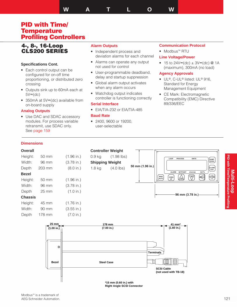
Mu
lti-Lo
op
P
ID w
ith T
ime/T
emp
erature P
rofilin
gW A T L O W
PID with Time/TemperatureProfiling Controllers4-, 8-, 16-LoopCLS200 SERIES
Specifications Cont.
• Each control output can beconfigured for on-off time proportioning, or distributed zerocrossing
• Outputs sink up to 60mA each at5VÎ(dc)
• 350mA at 5VÎ(dc) available fromon-board supply
Analog Outputs
• Use DAC and SDAC accessorymodules. For process variableretransmit, use SDAC only. See page 159
Overall
Height: 50 mm (1.96 in.)
Width: 96 mm (3.78 in.)
Depth 203 mm (8.0 in.)
Bezel
Height: 50 mm (1.96 in.)
Width: 96 mm (3.78 in.)
Depth 25 mm (1.0 in.)
Chassis
Height: 45 mm (1.76 in.)
Width: 90 mm (3.55 in.)
Depth 178 mm (7.0 in.)
Dimensions
Alarm Outputs
• Independent process anddeviation alarms for each channel
• Alarms can operate any outputnot used for control
• User-programmable deadband,delay and startup suppression
• Global alarm output activateswhen any alarm occurs
• Watchdog output indicatescontroller is functioning correctly
Serial Interface
• EIA/TIA-232 or EIA/TIA-485
Baud Rate
• 2400, 9600 or 19200, user-selectable
Communication Protocol
• Modbus™ RTU
Line Voltage/Power
• 15 to 24VÎ(dc) ± 3VÎ(dc) @ 1A(maximum), 300mA (no load)
Agency Approvals
• UL®, C-UL® listed: UL® 916,Standard for Energy Management Equipment
• CE Mark: ElectromagneticCompatibility (EMC) Directive 89/336/EEC
YESCHNG
SP
RAMP SOAK
ALARMACK
NOMANAUTO
PROCESSLOOP
ALARM STATUS OUT%SETPOINT
UNITS
BACK ENTER
50 mm (1.96 in.)
96 mm (3.78 in.)
(1.00 in.) (7.00 in.) (1.60 in.)25 mm 178 mm 41 mm*
Bezel Steel Case
Terminals
SCSI Cable(not used with TB-18)
*15 mm (0.60 in.) with Right Angle SCSI Connector
Controller Weight
0.9 kg (1.98 lbs)
Shipping Weight
1.8 kg (4.0 lbs)
Modbus™ is a trademark ofAEG Schneider Automation. 121
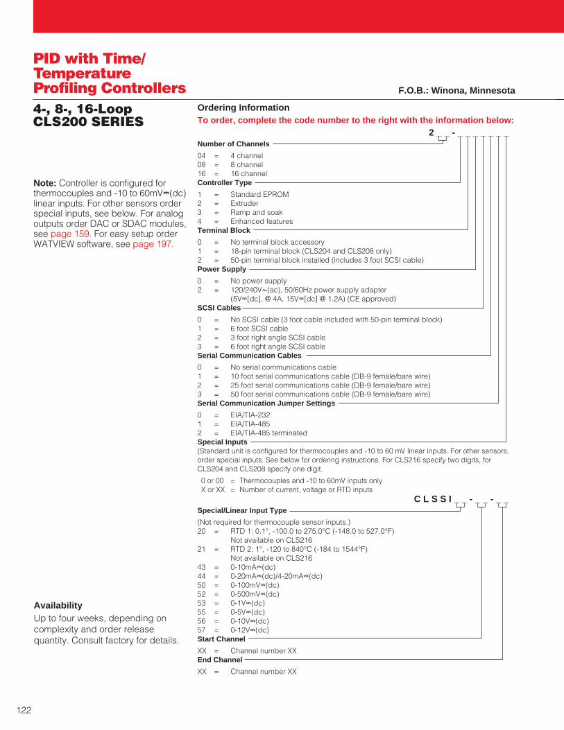
122
PID with Time/TemperatureProfiling Controllers4-, 8-, 16-LoopCLS200 SERIES
Ordering InformationTo order, complete the code number to the right with the information below:
2 _ _ - _ _ _ _ _ _ _Number of Channels
04 = 4 channel08 = 8 channel16 = 16 channel Controller Type
1 = Standard EPROM2 = Extruder 3 = Ramp and soak4 = Enhanced featuresTerminal Block
0 = No terminal block accessory1 = 18-pin terminal block (CLS204 and CLS208 only)2 = 50-pin terminal block installed (includes 3 foot SCSI cable)Power Supply
0 = No power supply2 = 120/240VÅ(ac), 50/60Hz power supply adapter
(5VÎ[dc], @ 4A, 15VÎ[dc] @ 1.2A) (CE approved)SCSI Cables
0 = No SCSI cable (3 foot cable included with 50-pin terminal block)1 = 6 foot SCSI cable2 = 3 foot right angle SCSI cable3 = 6 foot right angle SCSI cableSerial Communication Cables
0 = No serial communications cable1 = 10 foot serial communications cable (DB-9 female/bare wire)2 = 25 foot serial communications cable (DB-9 female/bare wire)3 = 50 foot serial communications cable (DB-9 female/bare wire)Serial Communication Jumper Settings
0 = EIA/TIA-2321 = EIA/TIA-4852 = EIA/TIA-485 terminatedSpecial Inputs(Standard unit is configured for thermocouples and -10 to 60 mV linear inputs. For other sensors,order special inputs. See below for ordering instructions. For CLS216 specify two digits, forCLS204 and CLS208 specify one digit.
0 or 00 = Thermocouples and -10 to 60mV inputs onlyX or XX = Number of current, voltage or RTD inputs
C L S S I _ _ - _ _ - _ _Special/Linear Input Type
(Not required for thermocouple sensor inputs.)20 = RTD 1: 0.1°, -100.0 to 275.0°C (-148.0 to 527.0°F)
Not available on CLS21621 = RTD 2: 1°, -120 to 840°C (-184 to 1544°F)
Not available on CLS21643 = 0-10mAÎ(dc)44 = 0-20mAÎ(dc)/4-20mAÎ(dc)50 = 0-100mVÎ(dc)52 = 0-500mVÎ(dc)53 = 0-1VÎ(dc)55 = 0-5VÎ(dc)56 = 0-10VÎ(dc)57 = 0-12VÎ(dc)Start Channel
XX = Channel number XXEnd Channel
XX = Channel number XX
AvailabilityUp to four weeks, depending oncomplexity and order releasequantity. Consult factory for details.
Note: Controller is configured forthermocouples and -10 to 60mVÎ(dc)linear inputs. For other sensors orderspecial inputs, see below. For analogoutputs order DAC or SDAC modules,see page 159. For easy setup orderWATVIEW software, see page 197.
F.O.B.: Winona, Minnesota

W A T L O W
123
PID with Time/TemperatureProfiling Controllers16-, 32-Loop MLS300 SERIES
Mu
lti-Lo
op
P
ID w
ith T
ime/T
emp
erature P
rofilin
g
The Watlow Anafaze MLS300 SERIESis a powerful line of controllers thatcombines performance and flexibilitywith compact design. The 16 and 32 loop versions provide completecontrol solutions for a broad range ofapplications. Support for multipletypes of sensor inputs is available;including thermocouples, RTDs,linear voltage, current and frequency.Each controller can operate as astand-alone system and includesbuilt-in serial communications forcomputer interface and dataacquisition. Ramp and soak featuresallow complex batch processing andsequencing. Up to 17 ramp and soakprofiles can be programmed with upto 20 steps each. Individual loopscan be configured for standardcontrol or ramp and soak. Unusedcontrol outputs can be configured forevents, alarms and process variableretransmit.
The remote analog input optionsallow for shorter sensor wires andflexible mounting which reducessensor cost and installation time.Watlow’s new CIM option providesOEMs with a space and labor savingalternative to the standard AIMmodule. This innovation allows usersto construct a wiring harness toattach sensors via a connectorinstead of connecting individualwires to the controller.
The MLS300 SERIES controllers areUL® and C-UL® listed, meet therequirements of the EuropeanCommunity EMC Directive and carrythe CE mark.
Features and Benefits
Ramp and soak control of up to 16 heat and cool loops or 32 heat loops• Minimal panel space per loop
• Reduces installation time
• More reliable: fewer parts meanfewer failures
Auto-tuning• Less time tuning
• Achieve excellent control with lessexpertise
Menu guided operation with fulltext display• Set up controller quickly
• Easy to operate
Store and recall eight jobs• Change quickly from one process
to another
Multiple and mixed inputs• Easy to change sensor types at
the last minute
• Less to learn, less inventory
Sensor fail detection• Reduces time troubleshooting
reversed, shorted and opensensors
Watlow Anafaze’sWATVIEW software isideal to use with the MLS300 SERIES. Seepage 197 for moreinformation andordering details.
High/low process and deviationalarms for each input• Configure alarms as needed to
integrate with PLC or other controlelements
TIA/EIA-232 and 485communications• Use software to configure and
operate
• Integrate with other controllersand software
34 digital outputs• Flexible configuration: use outputs
as needed for control, alarms,process variable retransmit andramp soak events
CIM300 option• Small footprint per loop
• Reduced installation time
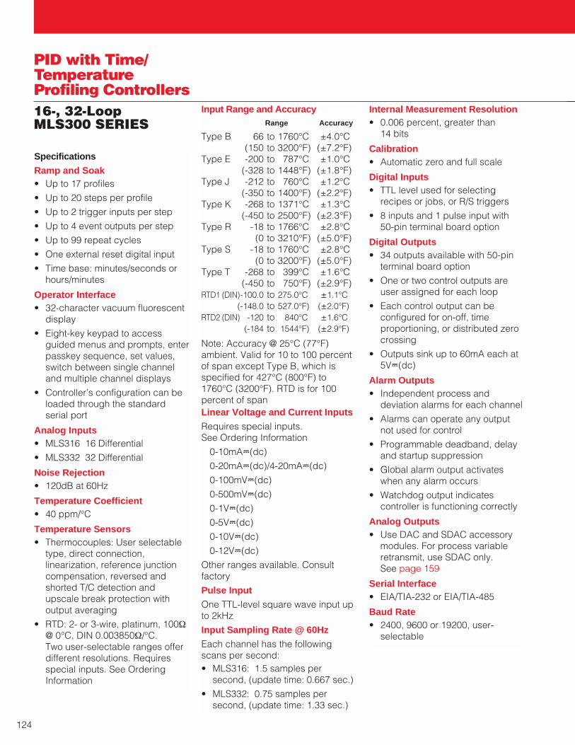
124
PID with Time/TemperatureProfiling Controllers16-, 32-Loop MLS300 SERIES
Specifications
Ramp and Soak• Up to 17 profiles
• Up to 20 steps per profile
• Up to 2 trigger inputs per step
• Up to 4 event outputs per step
• Up to 99 repeat cycles
• One external reset digital input
• Time base: minutes/seconds orhours/minutes
Operator Interface• 32-character vacuum fluorescent
display
• Eight-key keypad to accessguided menus and prompts, enterpasskey sequence, set values,switch between single channeland multiple channel displays
• Controller’s configuration can beloaded through the standardserial port
Analog Inputs• MLS316 16 Differential
• MLS332 32 Differential
Noise Rejection• 120dB at 60Hz
Temperature Coefficient• 40 ppm/°C
Temperature Sensors• Thermocouples: User selectable
type, direct connection, linearization, reference junctioncompensation, reversed andshorted T/C detection andupscale break protection withoutput averaging
• RTD: 2- or 3-wire, platinum, 100Ω@ 0°C, DIN 0.003850Ω/°C. Two user-selectable ranges offerdifferent resolutions. Requiresspecial inputs. See OrderingInformation
Input Range and AccuracyRange Accuracy
Type B 66 to 1760°C ±4.0°C(150 to 3200°F) (±7.2°F)
Type E -200 to 787°C ±1.0°C(-328 to 1448°F) (±1.8°F)
Type J -212 to 760°C ±1.2°C(-350 to 1400°F) (±2.2°F)
Type K -268 to 1371°C ±1.3°C(-450 to 2500°F) (±2.3°F)
Type R -18 to 1766°C ±2.8°C(0 to 3210°F) (±5.0°F)
Type S -18 to 1760°C ±2.8°C(0 to 3200°F) (±5.0°F)
Type T -268 to 399°C ±1.6°C(-450 to 750°F) (±2.9°F)
RTD1 (DIN)-100.0 to 275.0°C ±1.1°C(-148.0 to 527.0°F) (±2.0°F)
RTD2 (DIN) -120 to 840°C ±1.6°C(-184 to 1544°F) (±2.9°F)
Note: Accuracy @ 25°C (77°F)ambient. Valid for 10 to 100 percentof span except Type B, which isspecified for 427°C (800°F) to1760°C (3200°F). RTD is for 100percent of spanLinear Voltage and Current Inputs
Requires special inputs. See Ordering Information
0-10mAÎ(dc)
0-20mAÎ(dc)/4-20mAÎ(dc)
0-100mVÎ(dc)
0-500mVÎ(dc)
0-1VÎ(dc)
0-5VÎ(dc)
0-10VÎ(dc)
0-12VÎ(dc)
Other ranges available. Consultfactory
Pulse Input
One TTL-level square wave input upto 2kHz
Input Sampling Rate @ 60Hz
Each channel has the followingscans per second:• MLS316: 1.5 samples per
second, (update time: 0.667 sec.)
• MLS332: 0.75 samples persecond, (update time: 1.33 sec.)
Internal Measurement Resolution• 0.006 percent, greater than
14 bits
Calibration• Automatic zero and full scale
Digital Inputs• TTL level used for selecting
recipes or jobs, or R/S triggers
• 8 inputs and 1 pulse input with 50-pin terminal board option
Digital Outputs• 34 outputs available with 50-pin
terminal board option
• One or two control outputs areuser assigned for each loop
• Each control output can beconfigured for on-off, time proportioning, or distributed zerocrossing
• Outputs sink up to 60mA each at5VÎ(dc)
Alarm Outputs• Independent process and
deviation alarms for each channel
• Alarms can operate any outputnot used for control
• Programmable deadband, delayand startup suppression
• Global alarm output activateswhen any alarm occurs
• Watchdog output indicatescontroller is functioning correctly
Analog Outputs• Use DAC and SDAC accessory
modules. For process variableretransmit, use SDAC only. See page 159
Serial Interface• EIA/TIA-232 or EIA/TIA-485
Baud Rate• 2400, 9600 or 19200, user-
selectable

W A T L O W
125
PID with Time/TemperatureProfiling Controllers16-, 32-Loop MLS300 SERIES
Mu
lti-Lo
op
P
ID w
ith T
ime/T
emp
erature P
rofilin
g
Specifications Cont.
Communication Protocol• Modbus™ RTU
Line Voltage/Power• 15 to 24VÎ(dc) ± 3VÎ(dc) @ 1A
Agency Approvals• UL®, C-UL® Listed: UL® 916,
Standard for Energy ManagementEquipment
• CE Mark: ElectromagneticCompatibility (EMC) Directive89/336/EEC
Input Module Options
Choose the input moduleappropriate for the application:
• AIM316 and AIM332 provides screw terminations for 16 or 32sensors
• CIM316 and CIM332 provides DB-50 connector terminations for16 or 32 sensors in a compactsize
YESCHNG
SP
RAMPSOAK
ALARMACK
NOMANAUTO
PROCESSLOOP
ALARM STATUS
UNITS
BACK ENTER
SETPOINT OUT%
25 mm(1.00 in.)
188 mm(7.40 in.)
41 mm*(1.60 in.)
50 mm(1.96 in.)
Processor Module (Side)
*15 mm (0.60 in.) with Right Angle SCSI Connector
Processor Module (Front)
50 mm(1.96 in.)
96 mm(3.78 in.)

126
PID with Time/TemperatureProfiling Controllers16-, 32-Loop MLS300 SERIES
Ordering Information
To order, complete the code number to the right with the information below:3 _ _ - _ _ _ _ _ _ _ _ _
Input Module16 = 16 channel analog input module (AIM316)32 = 32 channel analog input module (AIM332)C1 = 16 channel compact input module (CIM316)C2 = 32 channel compact input module (CIM332)Processor Module (MLS300-PM)0 = Input module only (No MLS300-PM)1 = MLS300-PM with standard firmware2 = MLS300-PM with extruder firmware3 = MLS300-PM with enhanced features firmware4 = MLS300-PM with ramp and soak firmwareTerminal Block0 = No terminal block accessory1 = 50-pin terminal block, includes 3 foot SCSI cablePower Supply0 = None2 = 120/240VÅ(ac) 50/60Hz power supply adapter
[5VÎ(dc) @ 4A, 15VÎ(dc) @ 1.2A] CE approved SCSI Cables (For use with 50-pin terminal board)0 = No special SCSI cable (3 foot cable is included with 50-pin terminal board)1 = 6 foot SCSI cable2 = 3 foot right angle SCSI cable3 = 6 foot right angle SCSI cable Serial Communication Cables (For communications with computer)0 = No serial communications cable1 = 10 foot EIA/TIA-232 comm. cable, DB-9 female/RJ12 phone plug 2 = 25 foot EIA/TIA-232 comm. cable, DB-9 female/RJ12 phone plug 3 = 50 foot EIA/TIA-232 comm. cable, DB-9 female/RJ12 phone plug 7 = EIA/TIA-485 terminal block with 2 foot cable8 = EIA/TIA-485 terminal block with 4 foot cableModule Interconnect Cables0 = No special cable (4 foot cable comes with input module)1 = 10 foot cable, RJ45 connector/RJ45 connector2 = 25 foot cable, RJ45 connector/RJ45 connectorSerial Communication Jumper0 = EIA-TIA-2321 = EIA-TIA-4852 = EIA-TIA-485 Terminated Special Inputs(Standard unit is configured for thermocouples and -10 to 60mV linear inputs. For other sensors, order special inputs.)00 = Thermocouples and -10 to 60mV inputs onlyXX = Number of current, voltage, or RTD inputs. Include leading zero as needed
M L S 3 0 0 S I _ _ - _ _ - _ _Special Input Type20 = RTD 1: 0.1° Platinum, -100 to 275°C (-148 to 527°F)21 = RTD 2: 1° Platinum, -120 to 840°C (-184 to 1544°F)43 = 0-10mAÎ(dc)44 = 0-20mAÎ(dc)/4-20mAÎ(dc)50 = 0-100mVÎ(dc)52 = 0-500mVÎ(dc)53 = 0-1VÎ(dc)55 = 0-5VÎ(dc)56 = 0-10VÎ(dc)57 = 0-12VÎ(dc)Start ChannelXX = Channel number XXEnd ChannelXX = Channel number XX
AvailabilityUp to four weeks depending oncomplexity and order releasequantity. Consult factory for details.
F.O.B.: Winona, Minnesota
Analog Input Module(AIM332 shown)
146 mm H(5.75 in.)
165 mm L(6.5 in.) W
127 mm (5.0 in.)
Compact Input Module(CIM332 shown)
191 mm(7.50 in.)
70 mm(2.75 in.)
95 mm(3.75 in.)

Mu
lti-Lo
op
P
ID w
ith T
ime/T
emp
erature P
rofilin
gW A T L O W
127
SERIES F4D
PID with Time/TemperatureProfiling Controllers
Watlow’s SERIES F4D 1⁄4 DINindustrial controllers offer an easy to set up and operate solution forthe most demanding ramp and soak processing applications. Thefeatures and performance of theseunits make them ideally suited forenvironmental chamber or furnaceand oven applications. Single anddual channel versions are available.
These competitively pricedcontrollers feature a four line, highdefinition LCD interface display thatmakes profile programming andcontroller configuration significantlyfaster and easier. A 16 bitmicroprocessor supports all theaccuracy and performanceadvantages you have come toexpect from a Watlow controller.
Up to 256 steps can be program-med into as many as 40 nameableprofiles. Profiles can be program-med to wait for events or for up tothree different process variables. Aguaranteed soak feature allows youto set how closely your processneeds to be controlled.
Serial communication and dualalarm relays are included in thebase unit. The SERIES F4D rampingcontrollers are packaged with aNEMA 4X front face to withstandharsh environments and a four inchdeep case with removableconnectors for wiring convenience.
Performance Capabilities
• Accuracy to ±0.1 percent of span
• Operating environment:0 to 54°C (32 to 130°F)
Features and Benefits
Guided 256 step, 40 profile rampand soak programmable memory
• Supports a wide range ofprocessing applications
High definition four line LCDcontroller interface display
• Simplifies setup and operation
Menu customization
• Enhances process monitoring
High performance 16 bitmicroprocessor
• Precise process control
• 20Hz update rate on input 1
• 10Hz update rate on inputs 2 and 3
Universal inputs
• Allows application versatility
Expandable modular construction
• Field upgradable
F 4
1
2
i
1A1A
1B1B
2A2A
2B2B
Channel 1Temperature
Channel 2Humidity
Enhanced environmental chambercontrol
• Supports humidity, compressor,boost heat/boost cool control
Cascade control
• Allows precise two variable control
Real time clock with batterybackup
• Allows operational flexibility andpeace of mind
Field upgradeable firmware• Downloads available @ no charge
from www.watlow.com/F4
• Reduces downtime
• Eliminates the need for an RMA
Applications• Environmental chambers• Heat treating• Ovens and furnaces• Analytical equipment

PID with Time/TemperatureProfiling ControllersSERIES F4D
128
Specifications
Dimensions• Width x height x depth
(42 mm x 118 mm x 132 mm)3.96 in. x 3.96 in. x 3.85 in. panelmount
Universal Analog Inputs 1 (2-3 Optional)
Thermocouple• Type J, K, T, N, C (W5), E, Pt 2,
D (W3), B, R, S
RTD• 2- or 3-wire platinum, 100, 500 or
1000Ω
• JIS or DIN-curves, 1.0 or 0.1indication
Process• Range selectable: 0-10VÎ(dc),
0-5VÎ(dc), 1-5VÎ(dc), 0-50mV, 0-20mA, 4-20mA
• Voltage input impedance 20KΩ
• Current input impedance 100Ω
Digital Inputs (4)• Contact or dc voltage
• 10KΩ input impedance
• Update rate = 10Hz
Control Outputs (1A, 1B, 2A, 2B)
Open Collector/Switched dc• Internal load switching (nominal):
Switched dc, 22 to 28VÎ(dc),limited @ 30mA
• External load switching(maximum): Open collector42VÎ(dc) @ 0.5A
Solid State Relay• Zero switched, optically coupled,
0.5A @ 24VÅ(ac) minimum,253VÅ(ac) maximum
Process Outputs (OptionalRetransmit)• User selectable 0-10VÎ(dc),
0-5VÎ(dc), 1-5VÎ(dc), 0-20mA, 4-20mA
• Update rate = 1Hz
Alarm Outputs• Output update rate = 1Hz
• Electromechanical relay, Form C,2A @ 30VÎ(dc) or 240VÅ(ac)maximum
Digital Outputs (8)• Update rate = 10Hz
• Open collector output
• Off = 42VÎ(dc) max @ 10µA
• On = 0.2VÎ(dc) max @ 50mA sink
• Internal supply: 5VÎ(dc), 80mA
Communications
EIA-232 and EIA-485 serialcommunications with Modbus™ RTU protocol, 9600 or 19.2K baud
Safety and Agency Approvals• UL®/C-UL® 916 listed,
File # E185611 Process ControlEquipment
• IP65 and NEMA 4X
• CE to EN 61010-1 and EN 61326
Terminals• Touch-safe removable terminal
blocks, accepts 12 to 22 gaugewire
Power• 100-240VÅ(ac), -15 percent,
+10 percent; 50/60Hz, ±5 percent
• 24-28Vı(ac/dc), -15 percent, +10 percent (order option)
• 39VA max power consumption
• Data retention upon power failurevia nonvolatile memory (7 years for battery backed RAM).Sensor input isolation from inputto input to output to communi-cation circuitry is 500VÅ(ac)
Operating Environment• 0 to 55°C (32 to 130°F)
• 0 to 90 percent RH, non-condensing
• Storage temperature: -40 to 70°C (-40 to 158°F)
Accuracy• Calibration accuracy and sensor
conformity: ±0.1 percent of span±1°C @ 25°C ±3°C (77°F ±5°F)ambient, and rated line voltage±10 percent with the followingexceptions:Type T: 0.12 percent of span for -200°C to -50°C (-328°F to -58°F)Types R and S: 0.15 percent of spanfor 0°C to 100°C (32°F to 212°F)Type B: 0.24 percent of span for870°C to 1700°C (1598°F to 3092°F)
• Accuracy span: Less than or equalto operating ranges, 540°C(1000°F) minimum
• Temperature stability: ±0.1°C/°C(±0.1°F/°F) rise in ambient forthermocouples
±0.05°C/°C (±0.05°F/°F) rise inambient for RTD sensors
Displays• Process: five seven segment
LED, red
• Control interface display: highdefinition LCD, green
Sensor Operating Ranges:
Type J 0 to 815°C(32 to 1500°F)
Type K -200 to 1370°C(-328 to 2500°F)
Type T -200 to 400°C(-328 to 750°F)
Type N 0 to 1300°C(32 to 2372°F)
Type E -200 to 800°C(-328 to 1470°F)
Type C 0 to 2315°C(32 to 4200°F)
Type D 0 to 2400°C(32 to 4352°F)
Pt 2 0 to 1395°C(32 to 2543°F)
Type R 0 to 1760°C(32 to 3200°F)
Type S 0 to 1760°C(32 to 3200°F)

Mu
lti-Lo
op
P
ID w
ith T
ime/T
emp
erature P
rofilin
gW A T L O W
PID with Time/TemperatureProfiling ControllersSERIES F4D
129
Type B 0 to 1816°C(32 to 3300°F)
RTD (DIN) -200 to 800°C(-328 to 1472°F)
RTD (JIS) -200 to 800°C(-328 to 1166°F)
Process: -19999 to 30,000 units
Sensor Accuracy Ranges:
Input ranges
Type J 0 to 750°C(32 to 1382°F)
Type K -200 to 1250°C(-328 to 2282°F)
Type T -200 to 350°C(-328 to 662°F)
Type N 0 to 1250°C(32 to 2282°F)
Type E -200 to 800°C(-328 to 1470°F)
Type C (W5) 0 to 2315°C(32 to 4200°F)
Type D (W3) 0 to 2400°C(32 to 4352°F)
Pt 2 0 to 1393°C(32 to 2540°F)
Type R 0 to 1450°C(32 to 2642°F)
Type S 0 to 1450°C(32 to 2642°F)
Type B 870 to 1700°C(1598 to 3092°F)
RTD (DIN) -200 to 800°C(-328 to 1472°F)
RTD (JIS) -200 to 630°C(-328 to 1166°F)
Process: -19999 to 30,000 units
108.81 mm(4.284 in.)
99.82 mm(3.930 in.)
99.82 mm(3.930 in.)
92 mm x 92 mm(3.622 in. x 3.622 in.)
Panel Cutout97.79 mm(3.850 in.)
108.05 mm(4.254 in.)
10.26 mm(0.404 in.)
Serial CommunicationEIA-232 and EIA-485 serialcommunication interfaces areincluded in the base unit of both theSERIES F4S (single channel) andthe SERIES F4D (dual channel)controllers. The baud rate isselectable as either 9600 or 19200baud. The protocol is Modbus™.
Optional RetransmitOptional retransmit capability isavailable to retransmit one or twovariables. These variables includeup to three process variables,control set points or percent loadpower. Update rate is 1Hz.
Temperature Sensor
Environmental Chamber
Humidity Sensor
Cool
Boost Cool
Humidify
De-Humidify
Heat
Boost Heat
1A
D08
D07
D06
2B
2A
1BChannel 1Temperature
Channel 2Humidity
CompressorCutout
Comp.
Bi-pass Valve
DIN-A-MITE
DIN-A-MITE
DIN-A-MITE
DIN-A-MITE
LN2 Valve
®
Temperature and Humidity Chamber Application
AlarmsTwo Form “C” electromechanicalalarm relays are included in thebase units. These alarms can beprogrammed as either process ordeviation alarms. The alarms can betied to up to three process variables.
Specifications Cont.

PID with Time/TemperatureProfiling ControllersSERIES F4D
130
AvailabilityUp to four weeks, depending oncomplexity and order releasequantity. Consult factory for details.
Ordering Information
To order, complete the code number on the right with the information below:F 4 D _ - _ _ _ _ - _ _ _ _
SERIES F4D = 1⁄4 DIN dual channel ramping controller
Dual Channel Ramping Controller
3 universal analog inputs, 4-digital inputs, 8-digital outputs, 2 alarms, EIA-232/485 commsPower Supply
H = 100-240Vı(ac/dc)L = 24-28Vı(ac/dc)Output 1A
C = Open collector/switched dcF = Process, 0-5, 1-5, 0-10VÎ(dc), 0-20mA, 4-20mAK = Solid state Form A, 0.5A amp relayOutput 1B
A = NoneC = Open collector/switched dcF = Process, 0-5, 1-5, 0-10VÎ(dc), 0-20mA, 4-20mAK = Solid state Form A, 0.5A amp relayOutput 2A
C = Open collector/switched dcF = Process, 0-5, 1-5, 0-10VÎ(dc), 0-20mA, 4-20mAK = Solid state Form A, 0.5A amp relayOutput 2B
A = NoneC = Open collector/switched dcF = Process, 0-5, 1-5, 0-10VÎ(dc), 0-20mA, 4-20mAK = Solid state Form A, 0.5A amp relayAuxiliary Retransmit Module
0 = None1 = Single retransmit output 0-5, 1-5, 0-10VÎ(dc), 0-20mA, 4-20mA2 = Dual retransmit outputs 0-5, 1-5, 0-10VÎ(dc), 0-20mA, 4-20mALanguage and RTD Options
1 = English w/100Ω RTD2 = German w/100Ω RTD3 = French w/100Ω RTD4 = Spanish w/100Ω RTD5 = English w/500 & IKΩ RTD6 = German w/500 & IKΩ RTD7 = French w/500 & IKΩ RTD8 = Spanish w/500 & IKΩ RTDDisplay and Custom OptionsRG = DisplayXX = Custom options
Set Point Ramp and SoakProgrammingThe enhanced programmingfeatures found in the SERIES F4Dramping controllers are the result oflistening to our customers’ demandfor greater capabilities with reducedprogramming complexity.
A profile guide leads the pro-grammer through the programmingprocess by offering choices for stepconfiguration. For better operatorrecognition profiles and digital I/Oused for events can be given namesof up to 10 characters in length.
Five step types including ramp,soak, jump, auto start and end offerthe programmer complete flexibility.Ramp steps can be based on timeor rate. Ramp and soak steps canbe programmed to wait for up tofour event inputs and three processvariables. Up to eight event outputsare step selectable. Since yourthermal systems characteristics maychange over its operating range, upto 10 sets of PID heat/coolparameters are step selectable. The auto start step can start aprofile based on a set date, a day of the week, or daily, the choice isyours. The jump step can be usedto jump within a profile or to anotherprofile. The end step terminates aprogram with the control outputsprogrammed to your processneeds.
F.O.B.: Winona, Minnesota
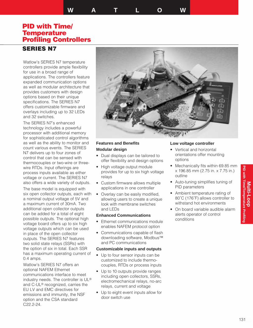
Mu
lti-Lo
op
P
ID w
ith T
ime/T
emp
erature P
rofilin
gW A T L O W
131
SERIES N7
PID with Time/TemperatureProfiling Controllers
Watlow’s SERIES N7 temperaturecontrollers provide ample flexibilityfor use in a broad range ofapplications. The controllers featureexpanded communication optionsas well as modular architecture thatprovides customers with designoptions based on their uniquespecifications. The SERIES N7 offers customizable firmware andoverlays including up to 32 LEDsand 32 switches.
The SERIES N7’s enhancedtechnology includes a powerfulprocessor with additional memoryfor sophisticated control algorithmsas well as the ability to monitor andcount various events. The SERIESN7 delivers up to four zones ofcontrol that can be sensed withthermocouples or two-wire or three-wire RTDs. Input offerings areprocess inputs available as eithervoltage or current. The SERIES N7also offers a wide variety of outputs.
The base model is equipped withsix open collector outputs, each witha nominal output voltage of 5V anda maximum current of 30mA. Twoadditional open collector outputscan be added for a total of eightpossible outputs. The optional highvoltage board offers up to six highvoltage outputs which can be usedin place of the open collectoroutputs. The SERIES N7 featurestwo solid state relays (SSRs) withthe option of six in total. Each SSRhas a maximum operating current of0.4 amps.
Watlow’s SERIES N7 offers anoptional NAFEM Ethernetcommunications interface to meetindustry needs. The controller is UL®
and C-UL® recognized, carries theEU LV and EMC directives foremissions and immunity, the NSFoption and the CSA standard C22.2-24.
Features and Benefits
Modular design
• Dual displays can be tailored tooffer flexibility and design options
• High voltage output moduleprovides for up to six high voltagerelays
• Custom firmware allows multipleapplications in one controller
• Overlay can be easily modified,allowing users to create a uniquelook with membrane switches and LEDs
Enhanced Communications
• Ethernet communications moduleenables NAFEM protocol option
• Communications capable of flashdownloading software, Modbus™and PC communications
Customizable inputs and outputs
• Up to four sensor inputs can becustomized to include thermo-couples, RTDs or process inputs
• Up to 10 outputs provide rangesincluding open collectors, SSRs,electromechanical relays, no-arc relays, current and voltage
• Up to eight event inputs allow fordoor switch use
Low voltage controller
• Vertical and horizontalorientations offer mounting options
• Mechanically fits within 69.85 mmx 196.85 mm (2.75 in. x 7.75 in.)outline
• Auto-tuning simplifies tuning ofPID parameters
• Ambient temperature rating of80˚C (176˚F) allows controller towithstand hot environments
• On board variable audible alarmalerts operator of controlconditions
132
PID with Time/TemperatureProfiling ControllersSERIES N7
Specifications
Control Mode
• Up to four zones of control, PID oron-off control
• Microprocessor based,programmable, direct-acting control outputs, flash download
• One step auto-tuning,WATCURVE temperature compensation
• Displayed in ˚C, ˚F or processvariable units
• Battery backed, real-time clock
• One non-isolated passive serialcommunications channel
• One non-isolated master serialcommunications channel
• Optional Ethernetcommunications module
• Optional high-voltage outputmodule
Agency Approvals
• UL® 60730, C-UL®
• EU LV Directive 72/23/EEC
• EU EMC Directive 89/336/EEC
• Emissions
• Immunity
• NSF option
• NAFEM NDP communications
• CSA standard E60730-209
Operator Interface
• Embedded membrane switch(LEDs and key switchesembedded in overlay)
• Up to 32 embedded LEDs and 32 embedded switches
• Contamination and water resistant(Supplied by Watlow or customer)
• Displays: Four character 14.22 mm (0.56 in.) high, sevensegment LED display and aneight character 5.08 mm (0.2 in.)dot matrix display
• Displays times, temperatures,user prompts and diagnosticcodes
• User selectable time andtemperature display formats.Time formats will include HH:MM,MM:SS, MMM:SS. Temperatureformats will be ˚C or ˚F
• Menu driven operation andmanual modes available
• Real time clock option displaystime of day
Accuracy
• Calibration accuracy and sensorconformity: ±1˚F for Type Jthermocouple and RTD
• Voltage ± 25mV
• Current ± 40µA
• Accuracy span: Normally 540˚C(1000˚F) minimum span
• Temperature stability
Configured Sensor Inputs
• Update rate: 5Hz
Thermocouple
• Requires ungroundedthermocouples
• Accuracy: ±1.1˚C (2˚F)
• Drift: ± 0.10˚C/˚C (±0.10˚F/˚F)
• Input ranges:
• Type J: -46˚C to 316˚C (-50˚F to 600˚F)
• Type K: -46˚C to 316˚C (-50˚F to 600˚F)
RTD
• 2- or 3-wire platinum
• DIN-curve (0.00385 curve)
• Accuracy: ±1.1˚C (2˚F)
• Drift: ± 0.10˚C/˚C (± 0.10˚F/˚F)
• Range: -46˚C to 316˚C (-50˚F to 600˚F)
Voltage
• Input impedance: 60kW
• Input range: 0 to 12V
• Accuracy: ± 25 mV
• Drift: ± 5mV/F
Current
• Input impedance: 100 W
• Input range: 0 to 22mA
• Accuracy: ± 40 mA
• Drift: ± 5 mA/F
Output Options
Switched DC Outputs
• 5V at 30mA maximum
Voltage Outputs
• Range: 0 to 12V at 50mAmaximum
• Minimum: load impedance 500 W
• Accuracy: ± 100mV
• Drift: ± 2.1mV/F
Current Output
• Range: 0 to 22mA at 20Vmaximum
• Maximum load impedance: 1000 W
• Accuracy: ± 100mA
• Drift: ± 4.3mA/F
DC Input
• Input high: 3 to 30V or >10kW
• Input low: -0.5 to 0.5V or <250W
Optional High Voltage Board
• Optional high voltage board hassix high-voltage outputs includingtwo standard SSR outputs. Theremaining four outputs can beSSRs, electromechanical or no arcrelays
• Relay specification:
• Operating temperature: 0˚ to 80˚C (0˚ to 176˚F)
• Contact type: normally open
• Maximum operating current: 8 Amps
• Maximum operating voltage:250VÅ(ac)
• 120/240VÅ(ac)
• 250VA pilot duty
• SSR specification
• Operating temperature: 0˚ to 80˚C (0˚ to 176˚F)
• Contact type: normally open

Mu
lti-Lo
op
P
ID w
ith T
ime/T
emp
erature P
rofilin
gW A T L O W
133
SERIES N7
PID with Time/TemperatureProfiling Controllers
Specifications Cont.
• Maximum operating current: 0.4 Amps
• Maximum operating voltage: 250VÅ(ac)
• 120/240VÅ(ac)
• 0.4A pilot duty
• No arc specification
• Operating temperature: 0˚ to 80˚C (0˚ to 176˚F)
• Contact type: normally open
• Maximum operating current: 8 amps
• Maximum operating voltage: 250VÅ(ac)
Power/Line Voltage
• 24VÅ(ac) power input (20.4 to26.4VÅ(ac))
• Class 2 power source required
• 47 to 63Hz
• 15VA maximum
• Program retention upon powerfailure via non-volatile memory
• Battery/real time clock option: 6 year lithium battery, provides power upon backuppower failure, operationresumption after power recovery,ability to display time of day
Audible Alarm
• Internal audible alarm, 85dB @10cm @ 2KHz. Output frequenciessupported: 250, 500, 1000, 2000,4000Hz
Operating Environment
• 0˚C to 80˚C (32˚F to 176˚F), 0 to90 percent relative humidity, non-condensing
Storage Temperature
• -40˚C to 80˚C (-40˚F to 176˚F)
Dimensions
• Vertical – 196.85 mm x 76.2 mm x50.8 mm (7.75 in. x 3 in. x 2 in.)
• Horizontal – 76.2 mm x 196.85 mmx 50.8 mm (3 in. x 7.75 in. x 2 in.)
Communications
• Communications parallelconnector:
• Supports addition of Ethernetcommunications board
• Support development ofadditional memory
• DB 9 communications connector:
• EIA-232 and EIA-485connections for:
• Flash download
• PC communications
• Modbus™ communications
• Expansion bus connector
For connection to expansiondevices such as:
• Motor speed control
• Encoder
• Multiple or custom displays
• Other custom remote I/O
Connectors
Connectors are customer supplied - Molex
• Standard I/O 16-pin connectorhousing – 43025-1600
• Optional I/O 14-pin connectorhousing – 43025-1400
• Pins – 43030-0007
High Voltage Module Adder BoardOrdering Information
• A007-2660-0000 – Two SSRs
• A007-2660-0001 – Two SSRs andfour mechanical relays
• A007-2660-0002 – Six SSRs
• A007-2660-0003 – Four SSRs and2 mechanical relays
• A007-2660-0004 – Two SSRs andfour no-arc relays
5-pin Master Communications Port
Input 2
14 Pins
9-pin Slave Communications Port
Input 3
16 Pins
123456
654321Input 4
Power Control Outputs 1 & 2
Event Inputs 1 to 4Event Outputs 1 to 4
Input 1
Control Outputs 3 & 4Process Outputs 1 & 2Event Inputs 5 to 8
High Voltage ModuleHigh-voltageControl Outputs 1 to 3
High Voltage ModuleHigh-voltage Control Outputs 4High-voltage Event Outputs 5 & 6
Location of Pins and Ports for Inputs and Outputs

134
PID with Time/TemperatureProfiling ControllersSERIES N7 Ordering Information
To order, complete the code number on the right with the information below.
N 7 _ _ - _ _ _ _ - _ _ _ _SERIES N7 = Up to four channels of microprocessor-basedtime and temperature control: 24VÅ(ac) power input
Abbreviation for Customer NameInput 1 and Input 2
1 = Dual thermocouple2 = Input 1 thermocouple / input 2 process input3 = Input 1 thermocouple / input 2 RTD4 = Dual process inputs5 = Input 1 RTD / input 2 process input6 = Dual RTD inputsInput 3 and Input 4
0 = None1 = Input 3 and 4 thermocouples2 = Input 3 process / input 4 thermocouple input3 = Input 3 RTD / input 4 thermocouple4 = Input 3 process input / input 4 process input5 = Input 3 RTD / input 4 process input6 = Input 3 RTD / input 4 RTDProcess Outputs, Event Inputs and Control Outputs0 = No events or process outputs
1 = 4 event inputs (rated @ 0 to 30V or contact closure) and 2 control outputs (rated for 5V @ 30mA)
2 = Current output 1 (0 to 20mA) with 4 event inputs and 2 control outputs
3 = Current outputs 1 and 2 (both are rated 0 to 20mA) with 4 event inputs and 2 control outputs
4 = Current output 1 and dc output 2 (rated 0 to 10V) with 4 event inputs and 2 control outputs
5 = DC output (rated 0 to 10V) with 4 event inputs and 2 control outputs
6 = DC outputs 1 and 2 with 4 event inputs and 2 control outputs
7 = DC output 1 and current output 2 with 4 event inputs and 2 control outputs
Add on Ethernet Module0 = None1 = Ethernet module boardAdd on High Voltage Module0 = None1 = 2 SSRs (rated at 0.4A, normally open)2 = 2 SSRs and 4 mechanical relays (rated at 8A, normally open)3 = 6 SSRs4 = 4 SSRs and 2 mechanical relays Display Options (Horizontal or Vertical)1 = Vertical2 = Horizontal left3 = Horizontal rightCustom Software and Options DesignatorXX = Made to order controller, code number assigned by factory
Notes:• If customer wants to use inputs 3 or 4 as
thermocouple, input 1 must also bethermocouple. Requires at least oneungrounded thermocouple.
• There is no option for suppression on anyof the high voltage outputs.
F.O.B.: Winona, Minnesota

Mu
lti-Lo
op
P
ID w
ith T
ime/T
emp
erature P
rofilin
gW A T L O W
135
PID with Time/TemperatureProfiling ControllersMINICHEF® 2000
MINICHEF® 2000 is an industry firstin an on-off or PID configurabletemperature/time and machine-function controller offering dozens ofpre-programmed applications. Thefoodservice equipment industry cannow rely on one product to providecontrol of many cooking applicationsincluding cook and hold ovens,convection ovens, deep-fat fryers,griddles and rotisseries. You caneasily switch the controller from oneapplication to another or customizeother applications by simplypressing a combination of keys.MINICHEF 2000 also adapts tochanging needs, evolving as theproduct or process changes.
Because MINICHEF 2000 canoperate different types of equipment,you can replace other controllers,simplifying inventory, manufacturingand reducing your supplier base.With a compact electrical case of 82.55 mm (3.25 in.) square x 50.8 mm(2 in.) deep, MINICHEF 2000enables new opportunities forspace-efficient equipment designs.
MINICHEF 2000 withstands therigorous conditions of a kitchenenvironment with an 80°C (176°F)ambient rating and superiorimmunity to electrical interference.
Performance Capabilities
• Thermometer accuracy to ±2°F
• Operating environment 0 to 80°C (32 to 176°F)
Features and Benefits
Configurable cooking controller
• Allows you to standardize on onecontroller simplifying inventory,manufacturing and reducingmultiple suppliers
Multiple inputs/outputs
• Control temperatures, times andmachine functions
Programmable menus
• Simplify repetitive tasks
Compact design
• Provides options for designingspace-efficient equipment
Economical
• Costs less than units with fewercapabilities
WATHELP diagnostics
• Simplifies operation andtroubleshooting
WATCURVE
• Compensates for temperaturedisturbances
“Smart Control”
• Optimizes system performance by calculating PID parametersautomatically
Mid-point alarms
• Enables even cooking by alertingthe user to an action such as stiror turn
Preheat option
• Prevents menu start untilequipment is pre-heated
Meets CE, UL®, CSA, NSF, AGAstandards
• Helps obtaining international andlocal code compliance
Three-year warranty
• Provides Control Confidence®
Applications
• Foodservice equipment
• Custom applications, consultfactory
Input 1Thermocoupleor RTD
Event Input 2
4 Inputs
A B
D
C
F
G H
E
Input 2Thermocoupleor RTD
Event Input 1
5 Outputs
Output 1Switched dc or solid-state relay
Output 2Switched dc or solid-state relay
Output 3Event Output 1
Output 4Event Output 2
Output 5Audible Alarm Output
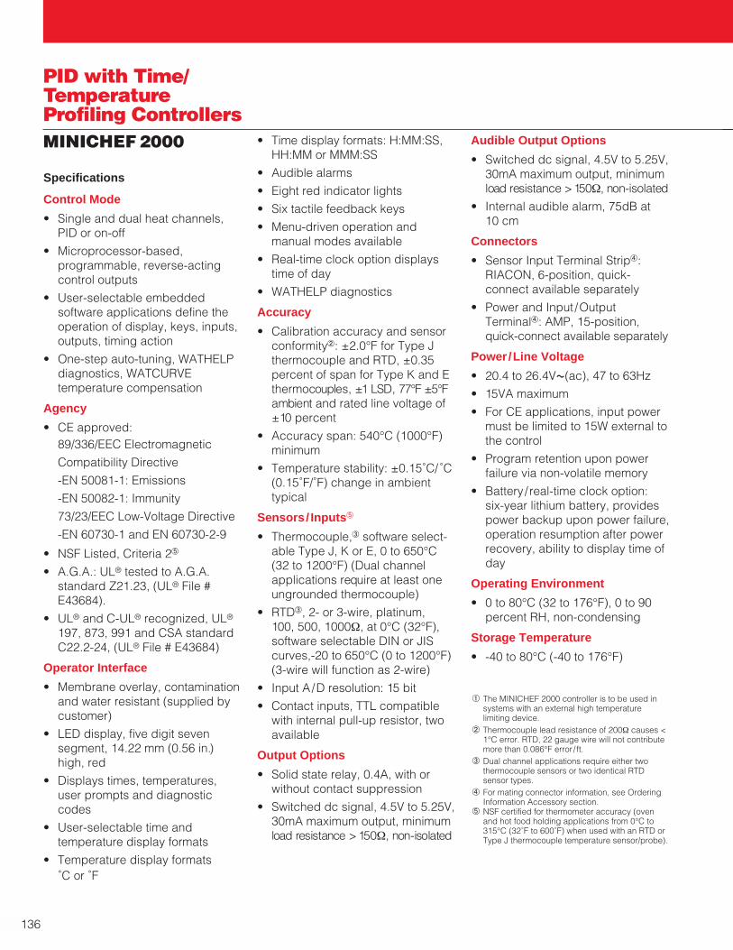
a The MINICHEF 2000 controller is to be used insystems with an external high temperaturelimiting device.
b Thermocouple lead resistance of 200Ω causes <1°C error. RTD, 22 gauge wire will not contributemore than 0.086°F error / ft.
c Dual channel applications require either twothermocouple sensors or two identical RTDsensor types.
d For mating connector information, see OrderingInformation Accessory section.
e NSF certified for thermometer accuracy (ovenand hot food holding applications from 0°C to315°C (32˚F to 600˚F) when used with an RTD orType J thermocouple temperature sensor/probe).
136
PID with Time/TemperatureProfiling ControllersMINICHEF 2000
Specifications
Control Mode
• Single and dual heat channels,PID or on-off
• Microprocessor-based,programmable, reverse-acting control outputs
• User-selectable embeddedsoftware applications define theoperation of display, keys, inputs,outputs, timing action
• One-step auto-tuning, WATHELPdiagnostics, WATCURVEtemperature compensation
Agency
• CE approved:89/336/EEC Electromagnetic
Compatibility Directive
-EN 50081-1: Emissions
-EN 50082-1: Immunity
73/23/EEC Low-Voltage Directive
-EN 60730-1 and EN 60730-2-9
• NSF Listed, Criteria 2e
• A.G.A.: UL® tested to A.G.A.standard Z21.23, (UL® File #E43684).
• UL® and C-UL® recognized, UL®
197, 873, 991 and CSA standardC22.2-24, (UL® File # E43684)
Operator Interface
• Membrane overlay, contaminationand water resistant (supplied bycustomer)
• LED display, five digit sevensegment, 14.22 mm (0.56 in.)high, red
• Displays times, temperatures,user prompts and diagnosticcodes
• User-selectable time andtemperature display formats
• Temperature display formats˚C or ˚F
• Time display formats: H:MM:SS,HH:MM or MMM:SS
• Audible alarms
• Eight red indicator lights
• Six tactile feedback keys
• Menu-driven operation andmanual modes available
• Real-time clock option displaystime of day
• WATHELP diagnostics
Accuracy
• Calibration accuracy and sensorconformityb: ±2.0°F for Type Jthermocouple and RTD, ±0.35percent of span for Type K and Ethermocouples, ±1 LSD, 77°F ±5°Fambient and rated line voltage of±10 percent
• Accuracy span: 540°C (1000°F)minimum
• Temperature stability: ±0.15˚C/˚C(0.15˚F/˚F) change in ambienttypical
Sensors/ Inputse
• Thermocouple,c software select-able Type J, K or E, 0 to 650°C(32 to 1200°F) (Dual channelapplications require at least oneungrounded thermocouple)
• RTDc, 2- or 3-wire, platinum, 100, 500, 1000Ω, at 0°C (32°F),software selectable DIN or JIScurves,-20 to 650°C (0 to 1200°F)(3-wire will function as 2-wire)
• Input A/D resolution: 15 bit
• Contact inputs, TTL compatiblewith internal pull-up resistor, twoavailable
Output Options
• Solid state relay, 0.4A, with orwithout contact suppression
• Switched dc signal, 4.5V to 5.25V,30mA maximum output, minimumload resistance > 150Ω, non-isolated
Audible Output Options
• Switched dc signal, 4.5V to 5.25V,30mA maximum output, minimumload resistance >150Ω, non-isolated
• Internal audible alarm, 75dB at 10 cm
Connectors
• Sensor Input Terminal Stripd:RIACON, 6-position, quick-connect available separately
• Power and Input /OutputTerminald: AMP, 15-position,quick-connect available separately
Power/Line Voltage
• 20.4 to 26.4VÅ(ac), 47 to 63Hz
• 15VA maximum
• For CE applications, input powermust be limited to 15W external tothe control
• Program retention upon powerfailure via non-volatile memory
• Battery / real-time clock option: six-year lithium battery, providespower backup upon power failure,operation resumption after powerrecovery, ability to display time ofday
Operating Environment
• 0 to 80°C (32 to 176°F), 0 to 90percent RH, non-condensing
Storage Temperature
• -40 to 80°C (-40 to 176°F)

Mu
lti-Lo
op
P
ID w
ith T
ime/T
emp
erature P
rofilin
gW A T L O W
137
PID with Time/TemperatureProfiling ControllersMINICHEF 2000 Ordering Information
To order, complete the code number on the right with the information below:
F 2 H A - _ _ _ 1 - _ _ A AMINICHEF 2000 = Cooking controller with numerous foodservice equipment application software sets, single and dual channel on-off or PID temperature regulation, timer and machine-function control, micro-processor-based, programmable, auto-tuning, WATCURVE, WATHELP diagnostics, 24VÅ(ac) power input, agency approved, flush mounted (mem-brane faceplate supplied by customer). Two switch contact event inputs
Inputs
1 = Dual thermocouple, Type J, K or E2 = Dual RTD, platinum, 100Ω, curve selectable3 = Dual RTD, platinum, 500Ω, curve selectable4 = Dual RTD, platinum, 1000Ω, curve selectableOutput 1
1 = Switched dc, 5V nominal, 30mA, non-isolated2 = Solid state relay, Form A, 0.4A, without RC suppression3 = Solid state relay, Form A, 0.4A, with RC suppressionOutput 2
1 = Switched dc, 5V nominal, 30mA, non-isolated2 = Solid state relay, Form A, 0.4A, without RC suppression3 = Solid state relay, Form A, 0.4A, with RC suppressionOutput 3 and 4
1 = Two event outputs, switched dc, 5V nominal, 30mA, non-isolatedBattery and Real-time Clock
0 = None1 = Includes battery and real-time clockAudible Alarm
0 = Alarm signal available at connector, switched dc, 5V nominal, 30mA, non-isolated
1 = Internal alarm includedSoftware
AA = Standard Food Equipment Application Software SetXX = Custom set-up parameters or Made-to-Order custom software.
Consult your local Watlow sales engineer. Code number assigned by factory
Specifications Cont.
Mechanical
• Case: polycarbonate Lexan® withadjustable mounting collar(vertical or horizontal orientation),designed for mounting on 16, 18,20 and 22 gauge panels
• Internal panel mounting requires aspecified panel cutout and four #6-32 studs or equivalent
• Vibration: 2g, 10 to 150Hz,applied in any one of three axes
Dimensions
• Overall width x height x depth:Horizontal105 mm x 83 mm x 51 mm (4.13 in. x 3.25 in. x 2.00 in.); Vertical83 mm x 105 mm x 51 mm (3.25 in. x 4.13 in. x 2.00 in.)(Assumes mating connectors areattached. Does not include wirebundle space requirements.)
Weight
• 6.50 oz maximum
Program Storage
• All non-embedded user andfactory programs are stored innon-volatile memory. Can bechanged by reprogramming
Sample/Update Rates
• 1 input: 4Hz
• 2 inputs: 4Hz
• PID: 1Hz
• Control outputs: 100Hz
• Display: 10Hz
F.O.B.: Winona, Minnesota
Lexan® is a registered trademark of General ElectricCorporation.
138
PID with Time/TemperatureProfiling ControllersMINICHEF 2000
MINICHEF 2000 Documentation Kit
0600-0006-0008 Rev A The Complete MINICHEF 2000 User Manual0600-0006-0010 Rev A MINICHEF 2000 Tutorial Diskette (31⁄2 inch)0600-0006-0000 Rev A MINICHEF 2000 General Setup Guide0600-0006-0001 Rev A MINICHEF 2000 Cook & Hold Application Guide0600-0006-0002 Rev A MINICHEF 2000 Convection Oven Application Guide0600-0006-0003 Rev A MINICHEF 2000 Deep-Fat Fryer Application Guide0600-0006-0004 Rev A MINICHEF 2000 Griddle Application Guide0600-0006-0005 Rev A MINICHEF 2000 Timer Application Guide0600-0006-0006 Rev A MINICHEF 2000 Shelf-Timer Application Guide0600-0006-0007 Rev A MINICHEF 2000 Rotisserie Application Guide
Code Number Description
Accessories0238-0679-0000
Prototyping and Training MembraneOverlay, adhesive-backed, 120.65 mm x120.65 mm (4.75 in. x 4.75 in.)
A001-0249-0001
120VÅ(ac) – 24VÅ(ac), stepdowntransformer, class 2, quick-connectterminals included
A001-0249-0002208/240VÅ(ac) – 24VÅ(ac), stepdowntransformer, class 2, quick-connectterminals included
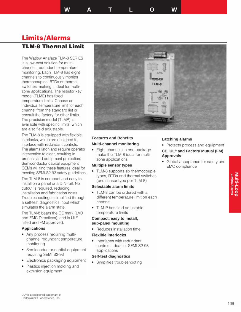
Mu
lti-Lo
op
L
imits
/Alarm
sW A T L O W
Limits /AlarmsTLM-8 Thermal Limit
The Watlow Anafaze TLM-8 SERIESis a low-cost solution for multi-channel, redundant temperaturemonitoring. Each TLM-8 has eightchannels to continuously monitorthermocouples, RTDs or thermalswitches, making it ideal for multi-zone applications. The resistor keymodel (TLME) has fixed temperature limits. Choose anindividual temperature limit for eachchannel from the standard list orconsult the factory for other limits. The precision model (TLMP) isavailable with specific limits, which are also field adjustable.
The TLM-8 is equipped with flexibleinterlocks, which are designed tointerface with redundant controls. The alarms latch and require operatorintervention to clear, resulting inprocess and equipment protection.Semiconductor capital equipmentOEMs will find these features ideal formeeting SEMI S2-93 safety guidelines.
The TLM-8 is compact and easy toinstall on a panel or a DIN-rail. Nocutout is required, reducinginstallation and fabrication costs.Troubleshooting is simplified througha self-test diagnostics input whichsimulates the alarm state.
The TLM-8 bears the CE mark (LVDand EMC Directives), and is UL®
listed and FM approved.
Applications
• Any process requiring multi-channel redundant temperaturemonitoring
• Semiconductor capital equipmentrequiring SEMI S2-93
• Electronics packaging equipment
• Plastics injection molding andextrusion equipment
Features and Benefits
Multi-channel monitoring
• Eight channels in one packagemake the TLM-8 ideal for multi-zone applications
Multiple sensor types
• TLM-8 supports six thermocoupletypes, RTDs and thermal switches(one sensor type per TLM-8)
Selectable alarm limits
• TLM-8 can be ordered with adifferent temperature limit on eachchannel
• TLM-P has field adjustabletemperature limits
Compact, easy to install, sub-panel mounting
• Reduces installation time
Flexible interlocks
• Interfaces with redundantcontrols; ideal for SEMI S2-93 applications
Self-test diagnostics
• Simplifies troubleshooting
UL® is a registered trademark ofUnderwriter’s Laboratories, Inc.
139
Latching alarms
• Protects process and equipment
CE, UL® and Factory Mutual (FM)Approvals
• Global acceptance for safety andEMC compliance

140
Limits /AlarmsTLM-8 Thermal Limit
Specifications
Analog Inputs• Eight sensor input channels
Sensor Inputs (Trip Point Ranges)• RTD 100Ω, platinum, 2-wire
(DIN-curve: -100 to 850°C (-148 to 1562°F)
• Thermal switch
• Type E T/C (TLME: 100 to 801°C (212 to 1474°F); TLMP: 100 to 660°C (212 to 1220°F))
• Type J T/C (100 to 754°C)(212 to 1389°F)
• Type K T/C (100 to 1205°C)(212 to 2201°F)
• Type R T/C (500 to 1720°C)(932 to 3128°F)
• Type S T/C (500 to 1711°C)(932 to 3112°F)
• Type T T/C (100 to 384°C)(212 to 723°F)
Accuracy• TLME: ±5 percent of trip point
• TLMP: ±1 percent of trip point
Repeatability• <5°C (41°F)
Digital Inputs• Alarm acknowledge digital input:
5-30VÎ(dc), optically isolated
• Alarm simulation digital input: 5-30VÎ(dc), optically isolated
Temperature Coefficient
• 40 ppm / °C accuracy
Alarm Outputs
For “fail safe” operation, relaycontacts are open in alarm andpower off condition• Global: 2 Form A (normally open)
electromechanical relays, latching
• Channel: 8 Form A (normally open)electromechanical relays, latching
• Maximum contact rating: 1A @125VÅ(ac) or 60VÎ(dc)
• UL® contact rating: 1A @30VÎ(dc)
Dimensions• 235 mm x 93 mm x 47 mm
(9.25 in. x 3.65 in. x 1.85 in.) (L x W x H), H = 66 mm (2.60 in.)with DIN mount option
Power Requirements• 10-26VÎ(dc) ±5 percent, 3.2
watts, class 2 power supply
Environmental• Temperature: 0 to 60°C (32 to
140°F) (operating); -20 to 100°C (-4 to 212°F) (storage)
• Relative humidity: 0-95 percent,non-condensing
Agency Approvals/Compliance• CE Directives:
Low Voltage Directive (LVD)73/23/EEC, Electromagnetic Compatibility(EMC) Directive 89/336/EEC
• UL® listed: UL® 916 and UL® 508
• C-UL® listed: CSA 22.2-205-M19
• Factory Mutual approval:temperature limit switches 3545
Miscellaneous• 8 individual alarm status LEDs
(Red)
• 1 supply power LED (Green)
C-UL® is a registered trademark ofUnderwriter’s Laboratories, Inc.

Mu
lti-Lo
op
L
imits
/Alarm
sW A T L O W
Limits /Alarms
141
TLME Trip Point Chart - (see Ordering Information, Option 4)
TLM-8 Thermal Limit
Temperature Trip Point
RTD
Unused Input A103˚C (217˚F) B121˚C (250˚F) C151˚C (304˚F) D215˚C (419˚F) E324˚C (615˚F) F404˚C (759˚F) G478˚C (892˚F) H584˚C (1083˚F) I708˚C (1306˚F) J824˚C (1515˚F) K
Type E T/C
Unused Input A101˚C (214˚F) B202˚C (396˚F) C302˚C (576˚F) D403˚C (756˚F) E502˚C (936˚F) F600˚C (1112˚F) G702˚C (1296˚F) H801˚C (1474˚F) I
Type J T/C
Unused Input A100˚C (212˚F) B152˚C (307˚F) C202˚C (396˚F) D251˚C (484˚F) E302˚C (576˚F) F350˚C (662˚F) G402˚C (756˚F) H450˚C (842˚F) I502˚C (936˚F) J554˚C (1027˚F) K600˚C (1112˚F) L653˚C (1207˚F) M704˚C (1299˚F) N754˚C (1389˚F) O
Type K T/C
Unused Input A100˚C (212˚F) B150˚C (302˚F) C200˚C (392˚F) D252˚C (486˚F) E303˚C (577˚F) F353˚C (667˚F) G401˚C (754˚F) H455˚C (851˚F) I504˚C (939˚F) J556˚C (1033˚F) K
Temperature Trip Point
Type K T/C (con’t)
603˚C (1117˚F) L651˚C (1204˚F) M701˚C (1294˚F) N753˚C (1387˚F) O807˚C (1485˚F) P851˚C (1564˚F) Q907˚C (1665˚F) R952˚C (1746˚F) S998˚C (1828˚F) T
1057˚C (1935˚F) U1101˚C (2014˚F) V1157˚C (2115˚F) W1205˚C (2201˚F) X
Type R T/C
Unused Input A501˚C (934˚F) B602˚C (1116˚F) C708˚C (1306˚F) D800˚C (1472˚F) E903˚C (1657˚F) F999˚C (1830˚F) G
1100˚C (2012˚F) H1206˚C (2203˚F) I1306˚C (2383˚F) J1410˚C (2570˚F) K1497˚C (2727˚F) L1593˚C (2899˚F) M1720˚C (3128˚F) N
Type S T/C
Unused Input A506˚C (943˚F) B601˚C (1114˚F) C700˚C (1292˚F) D810˚C (1490˚F) E902˚C (1656˚F) F
1005˚C (1841˚F) G1110˚C (2030˚F) H1210˚C (2210˚F) I1313˚C (2395˚F) J1404˚C (2559˚F) K1500˚C (2732˚F) L1600˚C (2912˚F) M1711˚C (3112˚F) N
Type T T/C
Unused Input A100˚C (212˚F) B202˚C (396˚F) C291˚C (556˚F) D384˚C (723˚F) E

If user specified trip points are ordered in the T L M P C H _ - _ _ _ _ TLMP part number, specify the followinginformation for each channel in the part description:
Channel NumberX = Channel number X (1-8)
Trip PointXXXX = Trip point in Celsius. Include leading zeros to make four digits.See table on page 141 for ranges for each sensor type. Unspecified channelswill be set to the default limit for the sensor.
TLMP = Precision model with adjustable limits T L M P - _ _ _ _ Sensor Type
0 = RTD1 = Type E T/C 2 = Type J T/C3 = Type K T/C4 = Type R T/C5 = Type S T/C6 = Type T T/C
Alarm Relays0 = Global relays only1 = Global alarm relays and 8 channel alarm relays
Mounting0 = Panel1 = DIN-rail
Trip PointU = User specified (specify trip points in description)D = Default trip points
142
Limits /AlarmsTLM-8 Thermal Limit
TLMP Trip Point Descriptions
Ordering InformationTo order, complete the code number to the right with the information below:
TLME = Fixed temperature limits model T L M E _ _ _ _ _ _ _ _ _ _ _Sensor Type
0 = RTD, 100Ω platinum/thermal switch1 = Type E T/C 2 = Type J T/C3 = Type K T/C4 = Type R T/C5 = Type S T/C6 = Type T T/C
Alarm Relays0 = Global alarm relays only1 = Global alarm relays and 8 channel alarm relays
Mounting0 = Panel1 = DIN-rail
Trip Point (see Trip Point chart on page 141)Channel 1Channel 2Channel 3Channel 4Channel 5Channel 6Channel 7Channel 8
F.O.B.: Winona, Minnesota
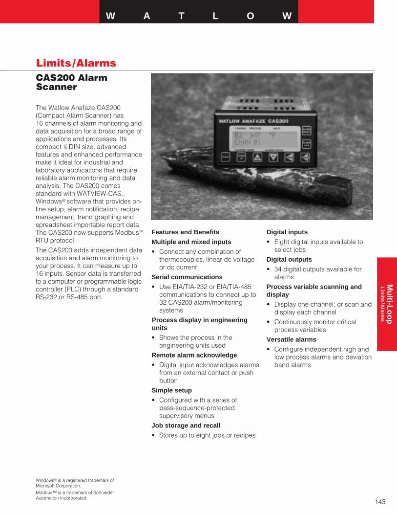
W A T L O W
143
Limits /AlarmsCAS200 AlarmScanner
Mu
lti-Lo
op
L
imits
/Alarm
s
Windows® is a registered trademark ofMicrosoft Corporation.Modbus™ is a trademark of SchneiderAutomation Incorporated.
The Watlow Anafaze CAS200(Compact Alarm Scanner) has 16 channels of alarm monitoring anddata acquisition for a broad range ofapplications and processes. Itscompact 1⁄8 DIN size, advancedfeatures and enhanced performancemake it ideal for industrial andlaboratory applications that requirereliable alarm monitoring and dataanalysis. The CAS200 comesstandard with WATVIEW-CAS,Windows® software that provides on-line setup, alarm notification, recipemanagement, trend graphing andspreadsheet importable report data.The CAS200 now supports Modbus™
RTU protocol.
The CAS200 adds independent dataacquisition and alarm monitoring toyour process. It can measure up to16 inputs. Sensor data is transferredto a computer or programmable logiccontroller (PLC) through a standardRS-232 or RS-485 port.
Features and Benefits
Multiple and mixed inputs
• Connect any combination ofthermocouples, linear dc voltageor dc current
Serial communications
• Use EIA/TIA-232 or EIA/TIA-485communications to connect up to32 CAS200 alarm/monitoringsystems
Process display in engineeringunits
• Shows the process in theengineering units used
Remote alarm acknowledge
• Digital input acknowledges alarmsfrom an external contact or pushbutton
Simple setup
• Configured with a series of pass-sequence-protectedsupervisory menus
Job storage and recall
• Stores up to eight jobs or recipes
Digital inputs
• Eight digital inputs available toselect jobs
Digital outputs
• 34 digital outputs available foralarms
Process variable scanning anddisplay
• Display one channel; or scan anddisplay each channel
• Continuously monitor criticalprocess variables
Versatile alarms
• Configure independent high andlow process alarms and deviationband alarms
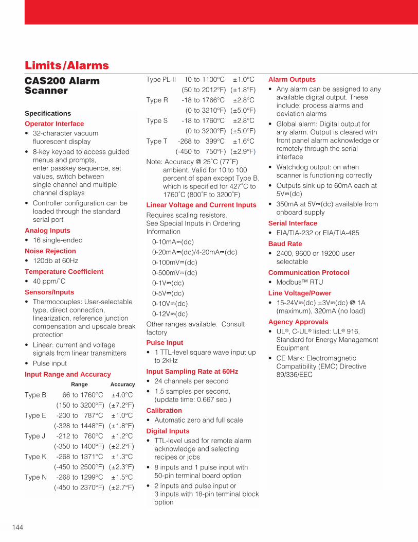
144
Limits /AlarmsCAS200 AlarmScanner
Specifications
Operator Interface • 32-character vacuum
fluorescent display
• 8-key keypad to access guidedmenus and prompts, enter passkey sequence, setvalues, switch between single channel and multiplechannel displays
• Controller configuration can beloaded through the standardserial port
Analog Inputs • 16 single-ended
Noise Rejection • 120db at 60Hz
Temperature Coefficient • 40 ppm/˚C
Sensors/Inputs • Thermocouples: User-selectable
type, direct connection,linearization, reference junctioncompensation and upscale breakprotection
• Linear: current and voltagesignals from linear transmitters
• Pulse input
Input Range and Accuracy Range Accuracy
Type B 66 to 1760°C ±4.0°C
(150 to 3200°F) (±7.2°F)
Type E -200 to 787°C ±1.0°C
(-328 to 1448°F) (±1.8°F)
Type J -212 to 760°C ±1.2°C
(-350 to 1400°F) (±2.2°F)
Type K -268 to 1371°C ±1.3°C
(-450 to 2500°F) (±2.3°F)
Type N -268 to 1299°C ±1.5°C
(-450 to 2370°F) (±2.7°F)
Type PL-II 10 to 1100°C ±1.0°C
(50 to 2012°F) (±1.8°F)
Type R -18 to 1766°C ±2.8°C
(0 to 3210°F) (±5.0°F)
Type S -18 to 1760°C ±2.8°C
(0 to 3200°F) (±5.0°F)
Type T -268 to 399°C ±1.6°C
(-450 to 750°F) (±2.9°F)
Note: Accuracy @ 25˚C (77˚F)ambient. Valid for 10 to 100percent of span except Type B,which is specified for 427˚C to1760˚C (800˚F to 3200˚F)
Linear Voltage and Current Inputs
Requires scaling resistors. See Special Inputs in OrderingInformation
0-10mAÎ(dc)
0-20mAÎ(dc)/4-20mAÎ(dc)
0-100mVÎ(dc)
0-500mVÎ(dc)
0-1VÎ(dc)
0-5VÎ(dc)
0-10VÎ(dc)
0-12VÎ(dc)
Other ranges available. Consultfactory
Pulse Input • 1 TTL-level square wave input up
to 2kHz
Input Sampling Rate at 60Hz• 24 channels per second
• 1.5 samples per second, (update time: 0.667 sec.)
Calibration• Automatic zero and full scale
Digital Inputs • TTL-level used for remote alarm
acknowledge and selectingrecipes or jobs
• 8 inputs and 1 pulse input with 50-pin terminal board option
• 2 inputs and pulse input or 3 inputs with 18-pin terminal blockoption
Alarm Outputs• Any alarm can be assigned to any
available digital output. Theseinclude: process alarms anddeviation alarms
• Global alarm: Digital output forany alarm. Output is cleared withfront panel alarm acknowledge orremotely through the serialinterface
• Watchdog output: on whenscanner is functioning correctly
• Outputs sink up to 60mA each at5VÎ(dc)
• 350mA at 5VÎ(dc) available fromonboard supply
Serial Interface • EIA/TIA-232 or EIA/TIA-485
Baud Rate• 2400, 9600 or 19200 user
selectable
Communication Protocol• Modbus™ RTU
Line Voltage/Power• 15-24VÎ(dc) ±3VÎ(dc) @ 1A
(maximum), 320mA (no load)
Agency Approvals• UL®, C-UL® listed: UL® 916,
Standard for Energy ManagementEquipment
• CE Mark: ElectromagneticCompatibility (EMC) Directive 89/336/EEC

W A T L O W
145
Limits /AlarmsCAS200 AlarmScanner
Mu
lti-Lo
op
L
imits
/Alarm
s
(1.00 in.) (7.00 in.) (2.00 in.)25 mm 178 mm 31 mm*
Bezel Steel Case
Terminals
SCSI Cable
*25 mm (1.00 in.) with Right Angle SCSI Connector
50 mm (1.96 in.)
96 mm (3.78 in.)
Dimensions

146
Limits /AlarmsCAS200 AlarmScanner
Ordering Information
To order, complete the code number to the right with the information below:
2 0 0 - _ _ _ _ _ _ _ _
Terminal Board0 = No terminal board accessory1 = 18-pin terminal block mounted on unit, no SCSI cable required2 = 50-pin terminal board (3 foot SCSI cable included)Power Supply0 = None2 = 120/240VÅ(ac) 50/60Hz power supply adapter
[5VÎ(dc) @ 4A, 15VÎ(dc) @ 1.2A] CE approved SCSI Cables 0 = No cable accessory (3 foot SCSI cable is included with
50-pin terminal board)1 = 6 foot SCSI cable2 = 3 foot right angle SCSI cable3 = 6 foot right angle SCSI cable Serial Communication Cables (For communications with computer)0 = 4 foot serial communication cable (DB-9 female/bare wire)1 = 10 foot serial communications cable (DB-9 female/bare wire) 2 = 25 foot serial communications cable (DB-9 female/bare wire) 3 = 50 foot serial communications cable (DB-9 female/bare wire) Scanner Software1 = WATVIEW-CAS Windows®-based softwareSerial Communication Jumper Settings0 = EIA/TIA-2321 = EIA/TIA-4852 = EIA/TIA-485 terminated Special Inputs(Standard unit is configured for thermocouples and -10 to 60 mV linear inputs. For other sensors, order special inputs)00 = Thermocouples and -10 to 60 mV inputs onlyXX = Number of current or voltage inputs. Include leading zero as needed
C A S S I _ _ - _ _ - _ _
Special Input Type43 = 0-10mAÎ(dc)44 = 0-20mAÎ(dc)/4-20mAÎ(dc)50 = 0-100mVÎ(dc)52 = 0-500mVÎ(dc)53 = 0-1VÎ(dc)55 = 0-5VÎ(dc)56 = 0-10VÎ(dc)57 = 0-12VÎ(dc)Start ChannelXX = Channel number XXEnd ChannelXX = Channel number XX
AvailabilityUp to four weeks depending oncomplexity and order releasequantity. Consult factory for details.
F.O.B.: Winona, Minnesota

W A T L O W
147
Mu
lti-Lo
op
PID
with
Pro
gram
mab
le Lo
gic
CPC400 SERIES
PID withProgrammable LogicControllers
The Watlow Anafaze CPC400controllers provide performance andflexibility in a compact design andintegrate full-featured closed-loopcontrol with user-written logic.Programmable logic can interactwith closed-loop control and operateI/O independently.
Four and eight loop versions offercomplete control solutions for abroad range of applications. TheCPC400 supports thermocouples,RTDs, linear voltage, current andfrequency. Built-in diagnosticsautomatically detect sensor failuresincluding open, shorted andreversed conditions. I/O can also beutilized for closed-loop control,alarms and user programs.
Using the built-in communicationsport, system designers can interfaceone or more controllers to a hostcomputer for operator controls anddata acquisition. The CPC400 offersPID, cascade, ratio and differentialcontrol strategies. Process variableretransmit and remote analog setpoint can be used to integrate theCPC400 with other devices such aschart recorders.
The CPC400 carries the CE markand is UL® listed.
Features and Benefits
Combines control loops withprogrammable logic
• Easy integration of PID controland logic
• Less time reinventing PID control
• Augment closed-loop control withuser-written logic
• Add custom functions to controller
• Reduces installation and setuptime
• Requires less panel space
• Fewer parts reduces failures andincreases reliability
Flexible, easy-to-use interfaces
• Easy setup with menu guided, full-text prompts
• Context-sensitive, on-screen helpsaves time
• WATVIEW software minimizessetup time
• Integrate with other serial devicesusing Modbus™
• Connect to system components viaanalog I/O to retransmit processvariables and read set points
Advanced control utilities
• Auto-tune optimizes control withminimal effort and expertise
• Cascade minimizes overshootand improves control in systemswith excessive thermal lag
• Ratio and differential enhancescontrol where the relationshipbetween two or more loops isparamount
Specifications
Operator Interface
• 32-character vacuum florescentdisplay
• Eight-key keypad to accessguided menus and prompts, setvalues and view channel displays
• Controller’s configuration can beloaded through the standardserial port
• Built-in context sensitive help
Noise Rejection
• 120dB at 60Hz
Temperature Coefficient
• 40ppm/°C
Programmable Logic
• Programming languages: LadderLogic, Sequential Function Chart,Function Block Diagram
• Memory: 64k flash (nonvolatile)
• Logic programs run concurrentlywith closed loop control
• Read/write access: controller I/Oand closed loop controlparameters
Watlow Anafaze’sWATVIEW andLOGICPRO softwareapplications are ideal touse with the CPC400SERIES. See page 197for more informationand ordering details.
UL® is a registered trademark of Underwriter’sLaboratories, Inc.Modbus™ is a registered trademark of SchneiderAutomation, Inc.
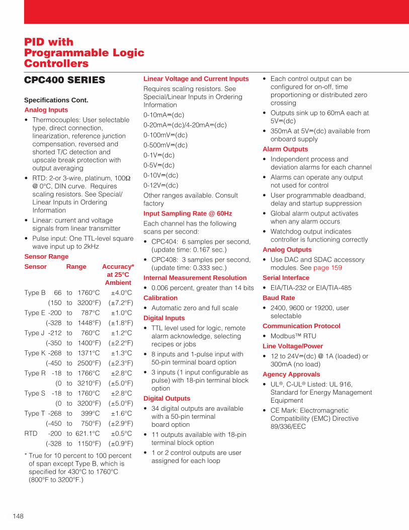
148
PID withProgrammable LogicControllersCPC400 SERIES
Analog Inputs
• Thermocouples: User selectabletype, direct connection,linearization, reference junctioncompensation, reversed andshorted T/C detection andupscale break protection withoutput averaging
• RTD: 2-or 3-wire, platinum, 100Ω@ 0°C, DIN curve. Requiresscaling resistors. See Special/Linear Inputs in OrderingInformation
• Linear: current and voltagesignals from linear transmitter
• Pulse input: One TTL-level squarewave input up to 2kHz
Sensor Range
Sensor Range Accuracy*at 25°C
Ambient
Type B 66 to 1760°C ±4.0°C
(150 to 3200°F) (±7.2°F)
Type E -200 to 787°C ±1.0°C
(-328 to 1448°F) (±1.8°F)
Type J -212 to 760°C ±1.2°C
(-350 to 1400°F) (±2.2°F)
Type K -268 to 1371°C ±1.3°C
(-450 to 2500°F) (±2.3°F)
Type R -18 to 1766°C ±2.8°C
(0 to 3210°F) (±5.0°F)
Type S -18 to 1760°C ±2.8°C
(0 to 3200°F) (±5.0°F)
Type T -268 to 399°C ±1.6°C
(-450 to 750°F) (±2.9°F)
RTD -200 to 621.1°C ±0.5°C
(-328 to 1150°F) (±0.9°F)
* True for 10 percent to 100 percentof span except Type B, which isspecified for 430°C to 1760°C(800°F to 3200°F.)
Linear Voltage and Current Inputs
Requires scaling resistors. SeeSpecial/Linear Inputs in OrderingInformation
0-10mAÎ(dc)
0-20mAÎ(dc)/4-20mAÎ(dc)
0-100mVÎ(dc)
0-500mVÎ(dc)
0-1VÎ(dc)
0-5VÎ(dc)
0-10VÎ(dc)
0-12VÎ(dc)
Other ranges available. Consultfactory
Input Sampling Rate @ 60Hz
Each channel has the followingscans per second:
• CPC404: 6 samples per second,(update time: 0.167 sec.)
• CPC408: 3 samples per second,(update time: 0.333 sec.)
Internal Measurement Resolution
• 0.006 percent, greater than 14 bits
Calibration
• Automatic zero and full scale
Digital Inputs
• TTL level used for logic, remotealarm acknowledge, selectingrecipes or jobs
• 8 inputs and 1-pulse input with50-pin terminal board option
• 3 inputs (1 input configurable aspulse) with 18-pin terminal blockoption
Digital Outputs
• 34 digital outputs are availablewith a 50-pin terminal board option
• 11 outputs available with 18-pinterminal block option
• 1 or 2 control outputs are userassigned for each loop
• Each control output can beconfigured for on-off, timeproportioning or distributed zerocrossing
• Outputs sink up to 60mA each at5VÎ(dc)
• 350mA at 5VÎ(dc) available fromonboard supply
Alarm Outputs
• Independent process anddeviation alarms for each channel
• Alarms can operate any outputnot used for control
• User programmable deadband,delay and startup suppression
• Global alarm output activateswhen any alarm occurs
• Watchdog output indicatescontroller is functioning correctly
Analog Outputs
• Use DAC and SDAC accessorymodules. See page 159
Serial Interface
• EIA/TIA-232 or EIA/TIA-485
Baud Rate
• 2400, 9600 or 19200, userselectable
Communication Protocol
• Modbus™ RTU
Line Voltage/Power
• 12 to 24VÎ(dc) @ 1A (loaded) or300mA (no load)
Agency Approvals
• UL®, C-UL® Listed: UL 916,Standard for Energy ManagementEquipment
• CE Mark: ElectromagneticCompatibility (EMC) Directive89/336/EEC
Specifications Cont.
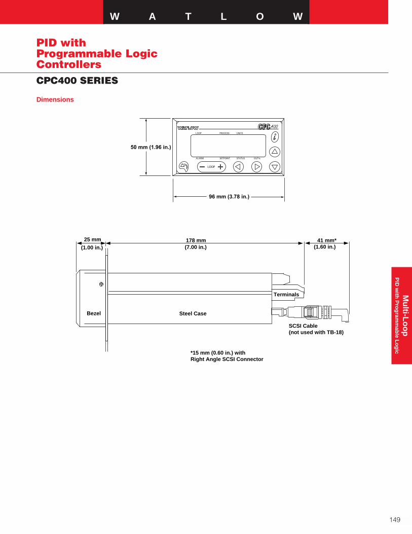
Dimensions
W A T L O W
149
Mu
lti-Lo
op
PID
with
Pro
gram
mab
le Lo
gic
CPC400 SERIES
PID withProgrammable LogicControllers
50 mm (1.96 in.)
96 mm (3.78 in.)
(1.00 in.) (7.00 in.) (1.60 in.)25 mm 178 mm 41 mm*
Bezel Steel Case
Terminals
SCSI Cable(not used with TB-18)
*15 mm (0.60 in.) with Right Angle SCSI Connector

Ordering InformationTo order, complete the model number on the right with the information below.
4 0 - 1
Number of Loops4 = 4 loops 8 = 8 loops Controller Type1 = Standard EPROM Terminal Board0 = No terminal board accessory1 = 18-pin terminal block mounted on unit (no SCSI cable required)2 = 50-pin terminal board (includes 3 foot SCSI cable)Power Supply0 = No power supply2 = 120/240VÅ(ac), 50/60Hz power supply adapter
(5VÎ[dc] @ 4A, 15VÎ[dc] @ 1.2A) (CE approved)SCSI Cables (For use with 50-pin terminal board)0 = No special SCSI cable (3 foot cable included with 50-pin terminal block)1 = 6 foot SCSI cable2 = 3 foot right angle SCSI cable3 = 6 foot right angle SCSI cableSerial Communication Cables (For communications with computer)0 = No serial communication cable1 = 10 foot serial communication cable (DB-9 female/bare wire)2 = 25 foot serial communication cable (DB-9 female/bare wire)3 = 50 foot serial communication cable (DB-9 female/bare wire)Serial Communication Jumper Settings 0 = EIA/TIA-2321 = EIA/TIA-4852 = EIA/TIA-485 terminatedSpecial Inputs(Standard unit is configured for thermocouples and -10 to 60mV linear inputs. For other sensors, order special inputs.) 0 = Thermocouples and -10 to 60mV inputs onlyX = Number of current, voltage or RTD inputs
Special InputsSpecify an input type for each channel or block of channels that needs factory installed resistors.Include a descriptor in the controller part description in the form specified below for each specialinput type. Make sure the number of special inputs specified is equal to the number of specialinputs in the controller part number.
C P C S I - -
Special Input Type (Not required for thermocouple sensor inputs)23 = RTD43 = 0-10mAÎ(dc)44 = 0-20mAÎ(dc)/4-20mAÎ(dc)50 = 0-100mVÎ(dc) 52 = 0-500mVÎ(dc)53 = 0-1VÎ(dc)55 = 0-5VÎ(dc)56 = 0-10VÎ(dc)57 = 0-12VÎ(dc)Start ChannelXX = Channel Number XXEnd ChannelXX = Channel Number XXAvailabilityUp to 4 weeks, depending on complexity and order release quantity. Consult factory for details.
150
PID withProgrammable LogicControllersCPC400 SERIES
F.O.B.: Winona, Minnesota
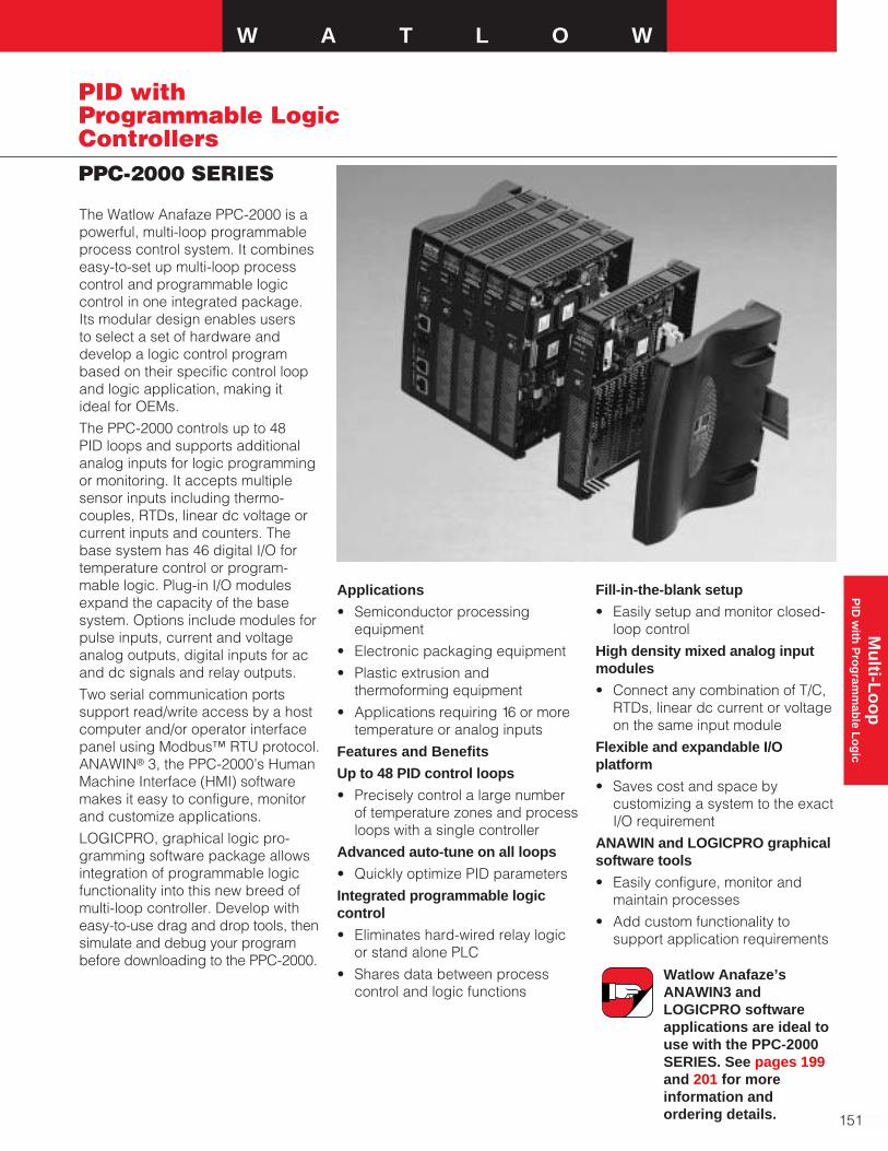
W A T L O W
151
Mu
lti-Lo
op
PID
with
Pro
gram
mab
le Lo
gic
PPC-2000 SERIES
PID withProgrammable LogicControllers
The Watlow Anafaze PPC-2000 is apowerful, multi-loop programmableprocess control system. It combines easy-to-set up multi-loop processcontrol and programmable logiccontrol in one integrated package.Its modular design enables usersto select a set of hardware anddevelop a logic control programbased on their specific control loopand logic application, making it ideal for OEMs.
The PPC-2000 controls up to 48 PID loops and supports additionalanalog inputs for logic programmingor monitoring. It accepts multiplesensor inputs including thermo-couples, RTDs, linear dc voltage orcurrent inputs and counters. Thebase system has 46 digital I/O fortemperature control or program-mable logic. Plug-in I/O modulesexpand the capacity of the basesystem. Options include modules forpulse inputs, current and voltageanalog outputs, digital inputs for acand dc signals and relay outputs.
Two serial communication portssupport read/write access by a hostcomputer and/or operator interfacepanel using Modbus™ RTU protocol.ANAWIN® 3, the PPC-2000’s HumanMachine Interface (HMI) softwaremakes it easy to configure, monitorand customize applications.
LOGICPRO, graphical logic pro-gramming software package allowsintegration of programmable logicfunctionality into this new breed ofmulti-loop controller. Develop witheasy-to-use drag and drop tools, thensimulate and debug your programbefore downloading to the PPC-2000.
Applications
• Semiconductor processingequipment
• Electronic packaging equipment
• Plastic extrusion andthermoforming equipment
• Applications requiring 16 or moretemperature or analog inputs
Features and Benefits
Up to 48 PID control loops
• Precisely control a large numberof temperature zones and processloops with a single controller
Advanced auto-tune on all loops
• Quickly optimize PID parameters
Integrated programmable logiccontrol
• Eliminates hard-wired relay logicor stand alone PLC
• Shares data between processcontrol and logic functions
Fill-in-the-blank setup
• Easily setup and monitor closed-loop control
High density mixed analog inputmodules
• Connect any combination of T/C,RTDs, linear dc current or voltageon the same input module
Flexible and expandable I/Oplatform
• Saves cost and space bycustomizing a system to the exactI/O requirement
ANAWIN and LOGICPRO graphicalsoftware tools
• Easily configure, monitor andmaintain processes
• Add custom functionality tosupport application requirements
Watlow Anafaze’sANAWIN3 andLOGICPRO softwareapplications are ideal touse with the PPC-2000SERIES. See pages 199and 201 for moreinformation andordering details.
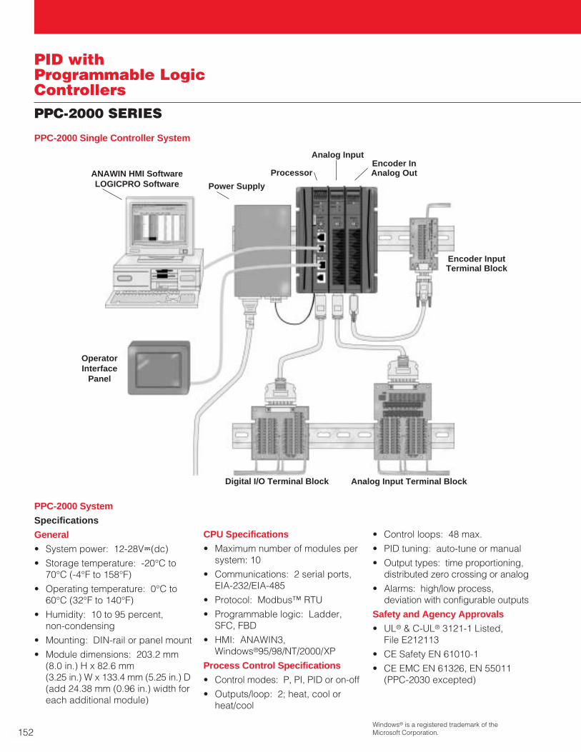
152
PID withProgrammable LogicControllersPPC-2000 SERIES
OperatorInterface
Panel
Processor
Analog InputEncoder InAnalog Out
Digital I/O Terminal Block Analog Input Terminal Block
Encoder Input Terminal Block
Power SupplyANAWIN HMI Software LOGICPRO Software
PPC-2000 System
Specifications
General
• System power: 12-28VÎ(dc)
• Storage temperature: -20°C to70°C (-4°F to 158°F)
• Operating temperature: 0°C to60°C (32°F to 140°F)
• Humidity: 10 to 95 percent, non-condensing
• Mounting: DIN-rail or panel mount
• Module dimensions: 203.2 mm(8.0 in.) H x 82.6 mm (3.25 in.) W x 133.4 mm (5.25 in.) D(add 24.38 mm (0.96 in.) width foreach additional module)
CPU Specifications
• Maximum number of modules persystem: 10
• Communications: 2 serial ports,EIA-232/EIA-485
• Protocol: Modbus™ RTU
• Programmable logic: Ladder,SFC, FBD
• HMI: ANAWIN3,Windows®95/98/NT/2000/XP
Process Control Specifications
• Control modes: P, PI, PID or on-off
• Outputs/loop: 2; heat, cool orheat/cool
• Control loops: 48 max.
• PID tuning: auto-tune or manual
• Output types: time proportioning,distributed zero crossing or analog
• Alarms: high/low process,deviation with configurable outputs
Safety and Agency Approvals
• UL® & C-UL® 3121-1 Listed, File E212113
• CE Safety EN 61010-1
• CE EMC EN 61326, EN 55011(PPC-2030 excepted)
PPC-2000 Single Controller System
Windows® is a registered trademark of theMicrosoft Corporation.
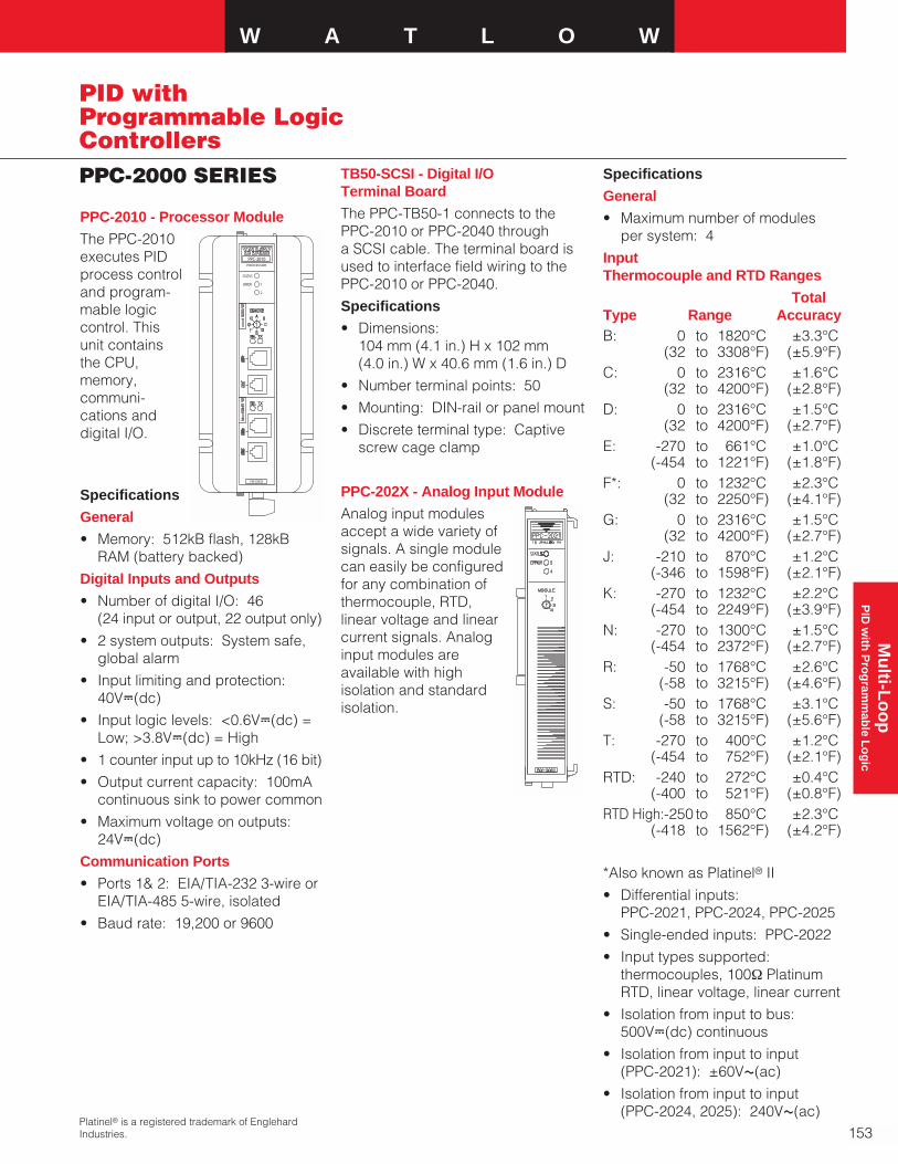
W A T L O W
153
Mu
lti-Lo
op
PID
with
Pro
gram
mab
le Lo
gic
PPC-2000 SERIES
PID withProgrammable LogicControllers
PPC-2010 - Processor Module
The PPC-2010executes PIDprocess controland program-mable logiccontrol. Thisunit containsthe CPU,memory,communi-cations anddigital I/O.
Specifications
General
• Memory: 512kB flash, 128kBRAM (battery backed)
Digital Inputs and Outputs
• Number of digital I/O: 46 (24 input or output, 22 output only)
• 2 system outputs: System safe,global alarm
• Input limiting and protection:40VÎ(dc)
• Input logic levels: <0.6VÎ(dc) =Low; >3.8VÎ(dc) = High
• 1 counter input up to 10kHz (16 bit)
• Output current capacity: 100mAcontinuous sink to power common
• Maximum voltage on outputs:24VÎ(dc)
Communication Ports
• Ports 1& 2: EIA/TIA-232 3-wire or EIA/TIA-485 5-wire, isolated
• Baud rate: 19,200 or 9600
TB50-SCSI - Digital I/O Terminal Board
The PPC-TB50-1 connects to thePPC-2010 or PPC-2040 througha SCSI cable. The terminal board isused to interface field wiring to thePPC-2010 or PPC-2040.
Specifications
• Dimensions: 104 mm (4.1 in.) H x 102 mm (4.0 in.) W x 40.6 mm (1.6 in.) D
• Number terminal points: 50
• Mounting: DIN-rail or panel mount
• Discrete terminal type: Captivescrew cage clamp
PPC-202X - Analog Input Module
Analog input modulesaccept a wide variety ofsignals. A single modulecan easily be configuredfor any combination ofthermocouple, RTD,linear voltage and linearcurrent signals. Analoginput modules areavailable with highisolation and standardisolation.
Specifications
General
• Maximum number of modules per system: 4
InputThermocouple and RTD Ranges
Total Type Range AccuracyB: 0 to 1820°C ±3.3°C
(32 to 3308°F) (±5.9°F)C: 0 to 2316°C ±1.6°C
(32 to 4200°F) (±2.8°F)D: 0 to 2316°C ±1.5°C
(32 to 4200°F) (±2.7°F)E: -270 to 661°C ±1.0°C
(-454 to 1221°F) (±1.8°F)F*: 0 to 1232°C ±2.3°C
(32 to 2250°F) (±4.1°F)G: 0 to 2316°C ±1.5°C
(32 to 4200°F) (±2.7°F)J: -210 to 870°C ±1.2°C
(-346 to 1598°F) (±2.1°F)K: -270 to 1232°C ±2.2°C
(-454 to 2249°F) (±3.9°F)N: -270 to 1300°C ±1.5°C
(-454 to 2372°F) (±2.7°F)R: -50 to 1768°C ±2.6°C
(-58 to 3215°F) (±4.6°F)S: -50 to 1768°C ±3.1°C
(-58 to 3215°F) (±5.6°F)T: -270 to 400°C ±1.2°C
(-454 to 752°F) (±2.1°F)RTD: -240 to 272°C ±0.4°C
(-400 to 521°F) (±0.8°F)RTD High:-250 to 850°C ±2.3°C
(-418 to 1562°F) (±4.2°F)
*Also known as Platinel® II
• Differential inputs:PPC-2021, PPC-2024, PPC-2025
• Single-ended inputs: PPC-2022
• Input types supported:thermocouples, 100Ω PlatinumRTD, linear voltage, linear current
• Isolation from input to bus:500VÎ(dc) continuous
• Isolation from input to input (PPC-2021): ±60VÅ(ac)
• Isolation from input to input (PPC-2024, 2025): 240VÅ(ac)
STATUS
ERROR
PROCESSOR
1
2
PXX-XXXXX
PPC-2010
Platinel® is a registered trademark of EnglehardIndustries.
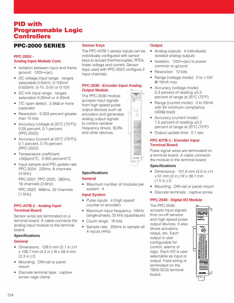
154
PID withProgrammable LogicControllersPPC-2000 SERIES
• Isolation between input and frameground: 120VÅ(ac)
• DC voltage input range: rangesselectable 0-50mV, 0-100mV, 0-500mV, 0-1V, 0-5V or 0-10V
• DC mA input range: rangesselectable 0-20mA or 4-20mA
• T/C open detect: 2.5kΩ or more(upscale)
• Resolution: 0.003 percent greaterthan 15 bits
• Accuracy (voltage at 25°C (75°F)):0.05 percent, 0.1 percent (PPC-2022)
• Accuracy (current at 25°C (75°F)):0.1 percent, 0.75 percent (PPC-2022)
• Temperature coefficient:<50ppm/°C, 0.005 percent/°C
• Input sample and PID update ratePPC-2024: 220ms, 8 channels(4.5Hz)
PPC-2021, PPC-2025: 380ms, 16 channels (2.6Hz)
PPC-2022: 666ms, 32 channels(1.5Hz)
PPC-AITB-1 - Analog InputTerminal Board
Sensor wires are terminated on aterminal board. A cable connects theanalog input module to the terminalboard.
Specifications
General
• Dimensions: 129.5 mm (5.1 in.) Hx 106.7 mm (4.2 in.) W x 58.4 mm(2.3 in.) D
• Mounting: DIN-rail or panelmount
• Discrete terminal type: captivescrew cage clamp
PPC-202X - Analog Input Module Cont.
Sensor Keys
The PPC-AITB-1 sensor inputs can beindividually configured with sensorkeys to accept thermocouples, RTDs,linear voltage and current. Sensorkeys used with PPC-2022 configure 2input channels.
PPC-2030 - Encoder Input AnalogOutput Module
The PPC-2030 moduleaccepts input signalsfrom high speed pulseoutput devices such asencoders and generatesanalog output signalsto control variablefrequency drives, SCRsand other devices.
Specifications
General
• Maximum number of modules persystem: 4
Input System
• Pulse inputs: 4 (high speedcounter or encoder)
• Maximum input frequency: 10kHz(single-phase), 32 kHz (quadrature)
• Count range: 16 bits
• Sample rate: 250ms to sample all4 inputs (4Hz)
Output
• Analog outputs: 4 individuallyisolated analog outputs
• Isolation: 120VÅ(ac) to powercommon or ground
• Resolution: 12 bits
• Range (voltage mode): 0 to +10V@ 10mA max
• Accuracy (voltage mode): 0.3 percent of reading ±0.5percent of range at 25°C (75°F)
• Range (current mode): 0 to 20mAwith 8V minimum compliance(400Ω load)
• Accuracy (current mode): 1.5 percent of reading ±0.2percent of range at 25°C (75°F)
• Output update time: 0.1 sec
PPC-EITB-1 - Encoder InputTerminal Board
Pulse signal wires are terminated ona terminal board. A cable connectsthe module to the terminal board.
Specifications
• Dimensions: 101.6 mm (4.0 in.) Hx 51 mm (2 in.) W x 38.1 mm (1.5 in.) D
• Mounting: DIN-rail or panel mount
• Discrete terminals: captive screw
PPC-2040 - Digital I/O Module
The PPC-2040accepts input signalsfrom on-off sensorsand high speed pulseoutput devices. It alsodrives actuators,relays, etc. Eachoutput is userconfigurable forcontrol, alarms orlogic. Each I/O is userselectable as input oroutput. Field wiring isterminated on theTB50-SCSI terminalboard.

W A T L O W
155
Mu
lti-Lo
op
PID
with
Pro
gram
mab
le Lo
gic
PPC-2000 SERIES
PID withProgrammable LogicControllers
Specifications
General
• Each point selectable as input or output
• 2 points selectable as input,output or counter/frequency
• Maximum number of modules per system: 6
Counter/Frequency
• Number: 2
• Maximum frequency: 10kHz(single-phase)
32kHz (quadrature)
• Sample rate: 250 ms (4Hz)
• Count range: 16 bits
Digital Input
• Number: 32
• Voltage limiting and protection:40VÎ(dc)
• Logic levels: <0.6VÎ(dc) = Low;>3.8VÎ(dc) = High
Digital Output
• Number: 32
• Maximum voltage: 24VÎ(dc)
• Maximum current: 150mA sink tocommon
PPC-2040 - Digital I/O Module Cont.
PPC-205X - Analog Output Module
The PPC-205X modulegenerates analog outputsignals to control powercontrollers, variablefrequency drives andother devices. Theanalog output module isavailable with 4 or 8outputs.
Specifications
General
• Maximum number of modules per system: 4
Output
• Number: 4 (isolated) or 8 (pairisolated)
• Current or voltage selectable
• Isolation from power common andearth ground: 120VÅ(ac)
• Isolation from output to output(PPC-2051): 120VÅ(ac)
• Isolation between output pairs(PPC-2050): 120VÅ(ac)
• Voltage range: 0-10VÎ(dc) @10mA maximum
• Current range: 0-20mA with 8Vmaximum compliance (400Ω load)
• Accuracy: ±0.5 percent voltage,± 0.8 percent current of range at25°C (75°F)
• Output update time: 0.1 second
• Resolution: 12 bit
PPC-206X - Digital Output Module
The PPC-206X relayoutput drives actuators,pilot lights and otherdevices. Each output isuser configurable foralarms or logic. Thedigital output module isavailable with 8 or 16relays.
Specifications
General
• Output status LEDs
• Maximum number of modules persystem: 6
Output
• Number: 8 or 16
• Contact voltage rating:240VÅ(ac), 30VÎ(dc)
• Relay type: Form A (SPST, NO onfault or inactive)
• Isolation: 240VÅ(ac) to powercommon or ground
• Maximum load current: 2A perrelay (PPC-2062), 1A per relay, 5A per common (PPC-2061)
• Commons: 8 (PPC-2062), 2 (PPC-2061)

156
PID withProgrammable LogicControllersPPC-2000 SERIES
PPC-207X - Digital Input Module
The PPC-207X accepts input signals from on-off sensors. The digital inputmodule is available with8 or 16 inputs.
Specifications
General
• Input status LEDs
• Maximum number of modules per system: 4
Input
• Number: 8 or 16
• Input range: 70-120VÅ(ac) ± 10 percent (PPC-2070/1), 12-24Vı(ac/dc) ± 10 percent(PPC-2072/3)
• Input response time: 32ms, 64 ms 12-20VÅ(ac)
• Logic levels: < 20VÅ(ac) = Low,>70VÅ(ac) = High (PPC-2070/1);< 3VÎ(dc) = Low, >10VÎ(dc) = High (PPC-2072/3)
PPC-IPS-2 - Power Supply
The PPC-IPS-2 supplies power to aPPC-2000 system which requires a12 to 28VÎ(dc) power source. Thepower supply also provides 5VÎ(dc)to drive digital outputs on theprocessor module.
Specifications
General
• Dimensions: 114.3 mm (4.5 in.) Hx 48.3 mm (1.9 in.) W x 215.9 mm(8.5 in.) D
• Mounting: DIN-rail or panel mount
• Input voltage: 120/240VÅ(ac),50/60Hz
• Output voltage: V1 +5VÎ(dc) at 6 amps
V2 +24VÎ(dc) at 4 amps
• Peak current output: 9A @5VÎ(dc); 6A @ 24VÎ(dc)
• Agency approvals: CE, UL® andC-UL® recognized
PPC-2010 - Processor ModuleOrdering InformationTo order, complete the model number on the right with the information below.
The PPC-2010 Processor Module includes ANAWIN3-CNF software for PPC-2000 configuration only and a TB50-SCSI digital I/O terminal board. A PPC-2000 system can have up to 10 modules.
Processor Module (with TB50)
Digital I/O Cable(Cable from module to terminal board)1 = 3 foot cable (CA-SCSI-3)2 = 6 foot cable (CA-SCSI-6)
Communication Cable(Cable between processor and host computer)1 = 10 foot EIA/TIA-232 cable,
Handset plug to DB9F (CA-232-DB910)2 = 25 foot EIA/TIA-232 cable,
Handset plug to DB9F (CA-232-DB925)3 = 50 foot EIA/TIA-232 cable,
Handset plug to DB9F (CA-232-DB950)4 = 10 foot EIA/TIA-232 cable,
Handset plug to DB25F (CA-232-DB2510)5 = 25 foot EIA/TIA-232 cable,
Handset plug to DB25F (CA-232-DB2525)6 = 50 foot EIA/TIA-232 cable,
Handset plug to DB25F (CA-232-DB2550)A= EIA/TIA-485 terminal block with 2 foot cableB= EIA/TIA-485 terminal block with 4 foot cable
Power Supply(DC power for the PPC-2000)0 = No power supply (customer provides own supply)2 = PPC-IPS-2 supply; 24VÎ(dc) @ 4 A and 5VÎ(dc) @ 6A
P P C - 2 0 1 0 -
F.O.B.: Winona, Minnesota

W A T L O W
157
Mu
lti-Lo
op
PID
with
Pro
gram
mab
le Lo
gic
PPC-2000 SERIES
PID withProgrammable LogicControllers
Ordering InformationTo order, complete the model number on the right with the information below.
Order up to four modules per system to accommodate sensor inputs. Do not exceed 128 inputs total. Only 48 inputs may be used for control. All modules accept T/Cs, current and voltage inputs. Only differential input modules accept RTDs. The high isolation modules provide 240VÅ(ac) protection between inputs and 120VÅ(ac) protection between input and ground. Each module includes an analog input terminal board with T/C/linear voltage keys (PPC-AITB-1). For other sensor input keys, see the special inputs section below.
Analog Input Modules (with AITB)1 = 16 channel module, differential inputs (PPC-2021)2 = 32 channel module, single-ended inputs (PPC-2022)3 = 4 channel high isolation module,
differential inputs (PPC-2023)4 = 8 channel high isolation module,
differential inputs (PPC-2024)5 = 16 channel high isolation module,
differential inputs (PPC-2025)
Analog Input Cable(Cable from module to terminal board)1 = 3 foot cable (CA-SCSI-3) 2 = 6 foot cable (CA-SCSI-6)
P P C - 2 0 2 -
PPC-202X - Analog Input Module
Ordering Information
To order, complete the model number on the right with the information below.
Each analog input terminal board ships configured with T/C sensor keys (this key can be also used for linear voltage). For other sensor types, choose from the special inputs below.
Input Type1 = Single ended current (two inputs per key)2 = Differential current 0-20mA (one input per key)3 = 3-wire RTD (one input per key)
Note:Contact the factory for fixed-configuration, analog input terminal boards in quantity.
P P C - S I K
PPC-SIKX - PPC Special Input Keys
F.O.B.: Winona, Minnesota
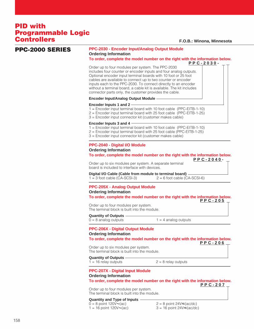
158
PID withProgrammable LogicControllersPPC-2000 SERIES PPC-2030 - Encoder Input/Analog Output Module
Ordering InformationTo order, complete the model number on the right with the information below.
Order up to four modules per system. The PPC-2030 includes four counter or encoder inputs and four analog outputs. Optional encoder input terminal boards with 10 foot or 25 foot cables are available to connect up to two counter or encoder inputs each to the PPC-2030. To connect directly to an encoder without a terminal board, a cable kit is available. The kit includes connector parts only, the customer provides the cable.
Encoder Input/Analog Output Module
Encoder Inputs 1 and 21 = Encoder input terminal board with 10 foot cable (PPC-EITB-1-10)2 = Encoder input terminal board with 25 foot cable (PPC-EITB-1-25)3 = Encoder input connector kit (customer makes cable)
Encoder Inputs 3 and 41 = Encoder input terminal board with 10 foot cable (PPC-EITB-1-10)2 = Encoder input terminal board with 25 foot cable (PPC-EITB-1-25)3 = Encoder input connector kit (customer makes cable)
P P C - 2 0 3 0 -
PPC-2040 - Digital I/O ModuleOrdering InformationTo order, complete the model number on the right with the information below.
Order up to six modules per system. A separate terminal board is included to interface with devices.
Digital I/O Cable (Cable from module to terminal board)1 = 3 foot cable (CA-SCSI-3) 2 = 6 foot cable (CA-SCSI-6)
P P C - 2 0 4 0 -
PPC-205X - Analog Output ModuleOrdering InformationTo order, complete the model number on the right with the information below.
Order up to four modules per system. The terminal block is built into the module.
Quantity of Outputs0 = 8 analog outputs 1 = 4 analog outputs
P P C - 2 0 5
PPC-206X - Digital Output ModuleOrdering InformationTo order, complete the model number on the right with the information below.
Order up to six modules per system. The terminal block is built into the module.
Quantity of Outputs1 = 16 relay outputs 2 = 8 relay outputs
P P C - 2 0 6
PPC-207X - Digital Input ModuleOrdering InformationTo order, complete the model number on the right with the information below.
Order up to four modules per system. The terminal block is built into the module.
Quantity and Type of Inputs0 = 8 point 120VÅ(ac) 2 = 8 point 24Vı(ac/dc)1 = 16 point 120VÅ(ac) 3 = 16 point 24Vı(ac/dc)
P P C - 2 0 7
F.O.B.: Winona, Minnesota
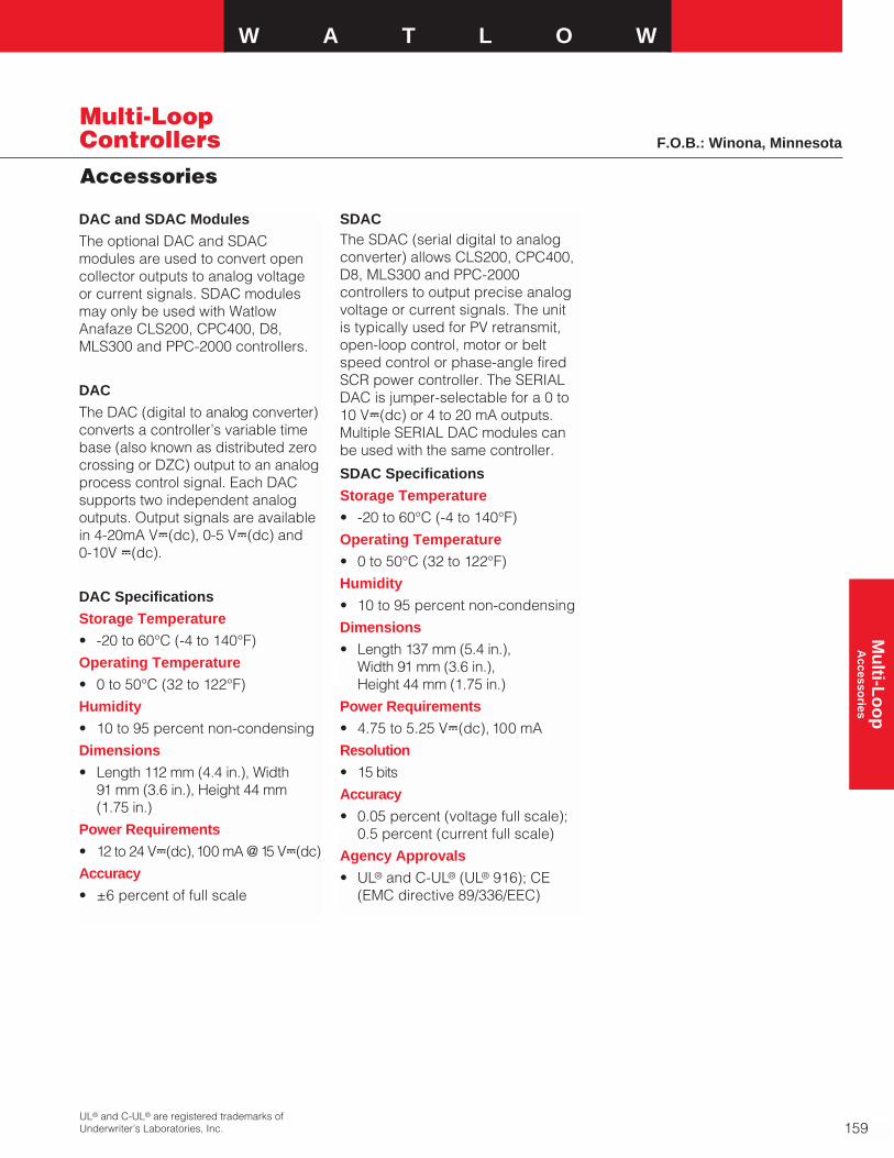
W A T L O W
159
Mu
lti-Lo
op
A
ccessories
Multi-LoopControllers F.O.B.: Winona, Minnesota
DAC and SDAC Modules
The optional DAC and SDACmodules are used to convert opencollector outputs to analog voltageor current signals. SDAC modulesmay only be used with WatlowAnafaze CLS200, CPC400, D8,MLS300 and PPC-2000 controllers.
DAC
The DAC (digital to analog converter)converts a controller’s variable timebase (also known as distributed zerocrossing or DZC) output to an analogprocess control signal. Each DACsupports two independent analogoutputs. Output signals are availablein 4-20mA VÎ(dc), 0-5 VÎ(dc) and 0-10V Î(dc).
DAC Specifications
Storage Temperature
• -20 to 60°C (-4 to 140°F)
Operating Temperature
• 0 to 50°C (32 to 122°F)
Humidity
• 10 to 95 percent non-condensing
Dimensions
• Length 112 mm (4.4 in.), Width 91 mm (3.6 in.), Height 44 mm(1.75 in.)
Power Requirements
• 12 to 24 VÎ(dc),100 mA @ 15 VÎ(dc)
Accuracy
• ±6 percent of full scale
SDACThe SDAC (serial digital to analogconverter) allows CLS200, CPC400,D8, MLS300 and PPC-2000controllers to output precise analogvoltage or current signals. The unit is typically used for PV retransmit,open-loop control, motor or beltspeed control or phase-angle firedSCR power controller. The SERIALDAC is jumper-selectable for a 0 to10 VÎ(dc) or 4 to 20 mA outputs.Multiple SERIAL DAC modules canbe used with the same controller.
SDAC Specifications
Storage Temperature
• -20 to 60°C (-4 to 140°F)
Operating Temperature
• 0 to 50°C (32 to 122°F)
Humidity
• 10 to 95 percent non-condensing
Dimensions
• Length 137 mm (5.4 in.), Width 91 mm (3.6 in.), Height 44 mm (1.75 in.)
Power Requirements
• 4.75 to 5.25 VÎ(dc), 100 mA
Resolution
• 15 bits
Accuracy
• 0.05 percent (voltage full scale);0.5 percent (current full scale)
Agency Approvals
• UL® and C-UL® (UL® 916); CE(EMC directive 89/336/EEC)
UL® and C-UL® are registered trademarks ofUnderwriter’s Laboratories, Inc.
Accessories

160
Multi-LoopControllers
Ordering Information
To order, complete the code number to the right with the information below:
DAC Type
1 = Dual digital to analog converter module (converts two DZC control outputs to two 0-5VÎ(dc) analog outputs). Separate power supply required
2 = Dual digital to analog converter module, (converts two DZC control outputs to two 0 - 10VÎ(dc) analog outputs). Power supply is separate
3 = Dual digital to analog converter module, (converts two DZC control outputs to two 4 - 20mAÎ(dc) analog outputs). Power supply is separate
4 = Serial digital to analog converter module (SDAC); provides one high precision isolated voltage or current analog output (range is setfrom the controller). Separate power supply required if more than 1 SDAC used
Additional Products
A = None
B = 120VÅ(ac) 60Hz wall mount power supply adapter (15VÎ[dc] @ 800mA, powers up to 8 dual DAC modules)
C = 120/240VÅ(ac) 50/60Hz panel mount power supply adapter (5VÎ[dc] @ 4A, 15VÎ[dc] @ 1.2A, powers up to 13 SDAC modules or 12 dual DAC modules)
D A C -
Accessories

W A T L O W
161
Po
wer C
on
trollers
DIN
-A-M
ITE
®
Power ControllersDIN-A-MITE® Family
Made in the United States ofAmerica, Watlow's DIN-A-MITE®
family of solid state power controllersprovides SCR control, heatsink, wiring and touch-safe exterior in one package. By designing the DIN-A-MITE® as a total powercontroller unit, the need to prepwires for terminals, find the right heat sink and determine adequateterminations is eliminated. It's acomplete package you can installwith Control Confidence®.
Performance Capabilities
Four DIN-A-MITE styles meet mostpower controller needs with ratingsfrom 18 to 100 amps with voltagesfrom 120 to 600VÅ(ac).
Features and Benefits
DIN-rail or sub-panel mounting
• Simple, fast installation
No mercury
• Environmentally safe product
Compact size
• Reduced panel space; less cost
Touch-safe exterior
Increased safety for installer/user
Easy Installation
Installation is simple and fast; savingtime and money. All you have to dois strip wires and make connections.
• Sub-panel or DIN-rail mounting
• No drilling and tapping necessary
• Same footprint as comparably rated MDRs
Agency Approvals• UL®508 listed and C-UL®
• UL®50, UL®1604, and CE
Achieve Optimum TemperatureControl With Variable Time BaseControlVariable time base control meets therapid switching demands of PIDtemperature control to deliver moreaccurate process control. It alsoincreases heater life by reducingtemperature over- and undershoot.
Low Electrical NoiseBurst firing switches ac current atzero cross (zero potential) toproduce minimal RFI and EMIelectric noise (radio frequencyinterference/electromagneticinterference). This low electricalnoise quality helps prevent
interference with sensor circuits andparticularly sensitive equipment inyour system.
Rugged, Back-to-Back SCRDesign Insures Long TermReliabilityWith solid state components, there'sno limit on the number of switchingcycles the DIN-A-MITE can perform.The four DIN-A-MITE styles meetmost application requirements bytolerating harsh industrialenvironments, electrical spikes anddissipating less power. Whenproperly applied, the DIN-A-MITEwill outlast all other types of non-electronic power controllers.
Single Contactor ac or dc, Proportional Voltage or Current
CurrentMonitor
Burst Fired to 100 Amps
DIN-A-MITE
Alarm
Phase-Angle Fired up to 80 Amps
COMPLIES WITH EUROPEAN
COMPLIES WITH EUROPEAN
EMC DIRECTIVE
EMC DIRECTIVE
EN 61326 (1997-98) and
EN 50178
Available on Request…
Consult Your Watlow Representative
UL® and C-UL® are registered trademarks ofthe Underwriter’s Laboratories, Inc.

162
Power ControllersDIN-A-MITE Family
Reduce Wear On Thermal SystemWith optional variable time baseswitching, the DIN-A-MITEautomatically adjusts output cycletime to meet system demands. The benefits of this option are:
• Heater output equal to loaddemand
• Minimized temperature over- andundershoot
Terminal System Helps PreventWiring FailuresA proven high-current copperterminal design ensures optimumelectrical connection to reduce heatbuild-up. This helps avoidconnection failures and ensuresoverall wiring reliability. To furtherreduce “hot spots,” we've eliminatedall unnecessary wires and fastenerswhich could possibly loosen, heat upand break down.
Compact Solid State PowerController Delivers BigPerformance in a Small PackageWatlow's DIN-A-MITE Style A, B, Cand D power controllers provide alow-cost, highly compact andversatile solid state power control.What's more, no need to worry aboutmercury; all DIN-A-MITEs aremercury free and fit the samefootprint as a comparably ratedMDR. Each feature sub-panelmounting, while Styles A, B and Calso have DIN-rail mountingcapability.
Style A CapabilitiesStyle A capabilities include single-phase burst fire switching up to 25amps at 600VÅ(ac) (see rating curve).
Variable time base, 4-20mAÎ(dc)process control or VÅ(ac)/ VÎ(dc)input contactor versions areavailable. All configurations are codenumber dependent and factoryselectable, 50/60Hz independent.
The standard sub-panel mountingfootprint is equal to that of an industrystandard mercury displacement relay.
DIN-A-MITE Style A, B, C and DFeatures• Faster switching with solid state
components. Better control savesenergy and extends heater life.
• Back-to-back SCR design forincreased durability.
• Three-year warranty assuresControl Confidence®.
Style B and C Features• 1- and 3-phase power permits
use in a variety of applications.
• Shorted output detector(optional) notifies a shorted SCRcondition.
Style C Features• Open heater detector (optional)
notifies when a partial or totallyopen heater occurs.
Style D Features• On-board semiconductor fusing
provides quick access with noextra mounting necessary.
• Optional load current monitordetects changes in load current.
Applications• Petroleum/chemical
• Ovens/furnaces
• Wave solder and reflow
• Packaging
• Foodservice equipment
• Semiconductor processing
Agency Approvals• UL® 508 Listed, File #E73741
• C-UL® approved
• CE approved with proper line filter
• DIN-A-MITE Style C thru-wallmount is also UL®50 and UL®1604approved.
• CE and EN 61326 IndustrialImmunity Class A emissions withfilter. EN 50178 safety directive
Style B CapabilitiesStyle B capabilities include 1-phaseand 3-phase burst fire up to 40 and33 amps, respectively, at 600VÅ(ac)(see rating curve).
Variable time base, 4-20mAÎ(dc)process control or VÅ(ac)/VÎ(dc)input contactor versions areavailable. All configurations are codenumber dependent and factoryselectable, 50/60Hz independent.
Style C CapabilitiesStyle C capabilities include 1-phaseand 3-phase, 2-leg, and 3-phase, 3-leg burst fire, as well as 1-phase,phase-angle fire. Burst fire operationfrom 120 to 600VÅ(ac), phase angleoperation from 120 to 600VÅ(ac).Current switching capabilities rangefrom 30 to 80 amps depending onthe model ordered (see output ratingcurve).
Input options include variable timebase, 4-20mAÎ(dc) process control,linear voltage control, manual controlor VÅ(ac)/VÎ(dc) contactor input.All configurations are code numberdependent and factory selectable.All models are 50/60Hz independent.
Style D CapabilitiesStyle D capabilities include 1-phaseswitching up to 100 amps at600VÅ(ac) and 30°C (86°F) (seerating curve). Limited 3-phaseoperation is possible by ganging twoand/or three Style D DIN-A-MITEcontactor inputs together.
Style D features on-boardsemiconductor fuses (accessiblefrom the front). Application is furtherenhanced with optional currenttransformer option for external loadcurrent monitoring and “shorted SCRdetector” on some models.
Variable time base, 4-20mAÎ(dc)process control or VÅ(ac)/ VÎ(dc)input contactor options are available.All configurations are code numberdependent and factory selectable,50/60Hz independent.
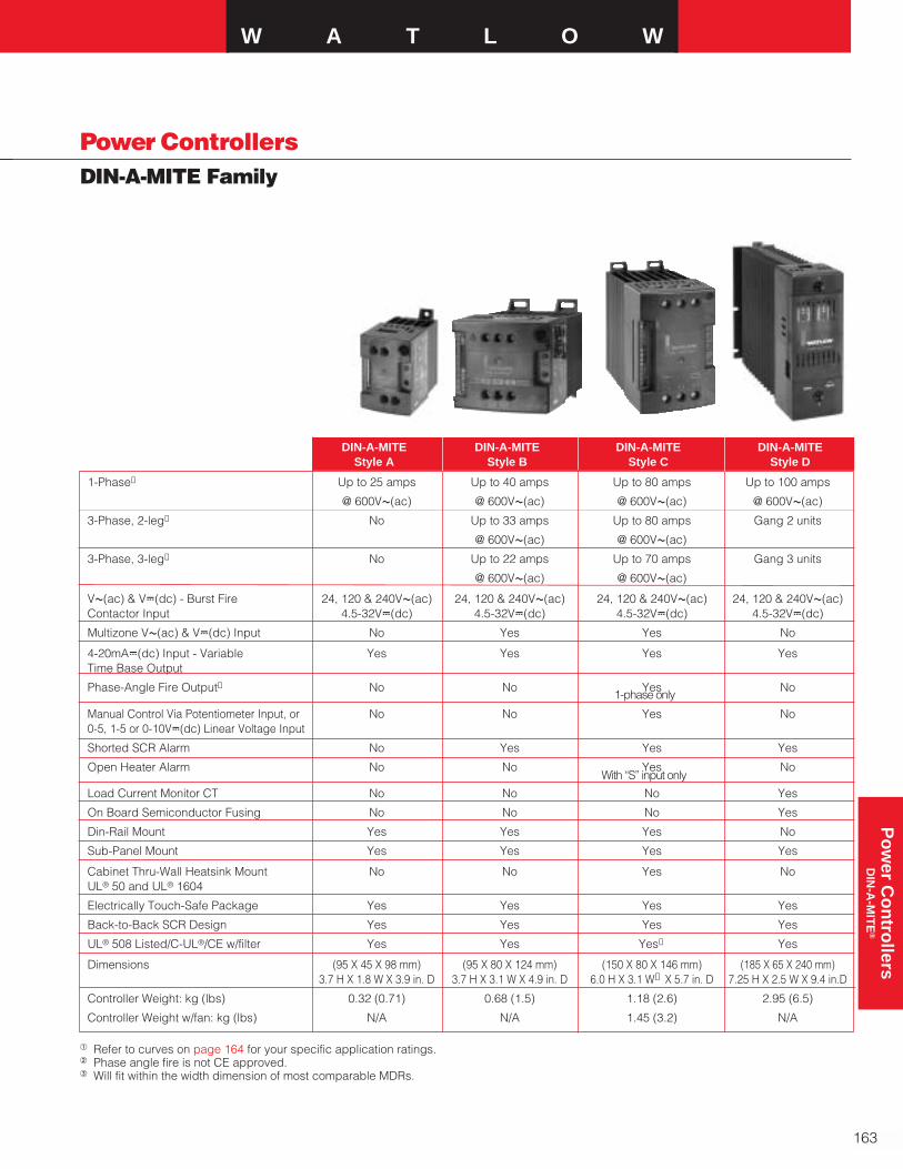
1-Phase① Up to 25 amps Up to 40 amps Up to 80 amps Up to 100 amps
@ 600VÅ(ac) @ 600VÅ(ac) @ 600VÅ(ac) @ 600VÅ(ac)
3-Phase, 2-leg① No Up to 33 amps Up to 80 amps Gang 2 units
@ 600VÅ(ac) @ 600VÅ(ac)
3-Phase, 3-leg① No Up to 22 amps Up to 70 amps Gang 3 units
@ 600VÅ(ac) @ 600VÅ(ac)
VÅ(ac) & VÎ(dc) - Burst Fire 24, 120 & 240VÅ(ac) 24, 120 & 240VÅ(ac) 24, 120 & 240VÅ(ac) 24, 120 & 240VÅ(ac)Contactor Input 4.5-32VÎ(dc) 4.5-32VÎ(dc) 4.5-32VÎ(dc) 4.5-32VÎ(dc)
Multizone VÅ(ac) & VÎ(dc) Input No Yes Yes No
4-20mAÎ(dc) Input - Variable Yes Yes Yes YesTime Base Output
Phase-Angle Fire Output➁ No No Yes No
Manual Control Via Potentiometer Input, or No No Yes No0-5, 1-5 or 0-10VÎ(dc) Linear Voltage Input
Shorted SCR Alarm No Yes Yes Yes
Open Heater Alarm No No Yes No
Load Current Monitor CT No No No Yes
On Board Semiconductor Fusing No No No Yes
Din-Rail Mount Yes Yes Yes No
Sub-Panel Mount Yes Yes Yes Yes
Cabinet Thru-Wall Heatsink Mount No No Yes NoUL® 50 and UL® 1604
Electrically Touch-Safe Package Yes Yes Yes Yes
Back-to-Back SCR Design Yes Yes Yes Yes
UL® 508 Listed/C-UL®/CE w/filter Yes Yes Yes➁ Yes
Dimensions (95 X 45 X 98 mm) (95 X 80 X 124 mm) (150 X 80 X 146 mm) (185 X 65 X 240 mm)3.7 H X 1.8 W X 3.9 in. D 3.7 H X 3.1 W X 4.9 in. D 6.0 H X 3.1 W➂ X 5.7 in. D 7.25 H X 2.5 W X 9.4 in.D
Controller Weight: kg (lbs) 0.32 (0.71) 0.68 (1.5) 1.18 (2.6) 2.95 (6.5)
Controller Weight w/fan: kg (lbs) N/A N/A 1.45 (3.2) N/A
W A T L O W
163
Po
wer C
on
trollers
DIN
-A-M
ITE
®
Power ControllersDIN-A-MITE Family
a Refer to curves on page 164 for your specific application ratings.b Phase angle fire is not CE approved.c Will fit within the width dimension of most comparable MDRs.
DIN-A-MITE DIN-A-MITE DIN-A-MITE DIN-A-MITEStyle A Style B Style C Style D
With “S” input only
1-phase only

164
Power ControllersDIN-A-MITE Family
Output Current Rating Curves
Style A Style B
Style C—Thru-Wall
Style C
30
25
20
15
10
5
0
25 30 35 40 45 50 55 60 65 70 75 80 85
Cu
rren
t (A
mp
s) in
to
a R
esis
tive
Lo
ad
Maximum Internal Enclosure Ambient Temperature (°C)
DIN-A-MITE Style A Ratings at 100% On
0 5 10 15 20 25 30 35 40 45 50 55 60
25
30
35
40
45
50
55
60
65
70
75
80
90
85
Current (Amps) into a Resistive Load
Max
imum
Inte
rnal
Enc
losu
re A
mbi
ent T
empe
ratu
re (°
C)
DIN-A-MITE Style B Ratings at 100% On
Natural Convection
3-ph
ase, 3 leg3-phase, 2 legS
ingle phase
0 5 10 15 20 25 30 35 40 45 50 55 60 65 70
25
30
35
40
45
50
55
60
65
70
Current (Amps) into a Resistive LoadMax
imum
Inte
rnal
Enc
losu
re A
mbi
ent T
empe
ratu
re (°
C)
DIN-A-MITE Style C Ratings at 100% On
75 80 85 90
Fan-Cooled
75
80
3-phase, 3 leg 3-phase, 2 leg
Single phase
0 5 10 15 20 25 30 35 40 45 50 55 60 65 70
Current (Amps) into a Resistive Load
25
30
35
40
45
50
55
60
65
70
75
80
Ambi
ent A
ir Ar
ound
Hea
tsin
k Fi
ns (
˚C)
DIN-A-MITE Style C Ratings at 100% On
Thru-Wall Heatsink
75 80
Recommended maximum enclosure temperature is 80˚ C (176˚ F)
3-phase, 2leg
3-phase, 3leg
Singlephase
0 5 10 15 20 25 30 35 40 45 50 55 60 65 70 75 80
25
30
35
40
45
50
55
60
65
70
75
80
90
85
Current (Amps) into a Resistive LoadMax
imu
m In
tern
al E
ncl
osu
re A
mb
ien
t T
emp
erat
ure
(°C
)
DIN-A-MITE Style C Ratings at 100% On
Natural Convection
3-phase, 3 leg3-phase, 2 leg
Single phase
0 5 10 15 20 25 30 35 40 45 50 55 60 65 70
25
30
35
40
45
50
55
60
65
70
75
80
85
Current (Amps) Into a Resistive Load
Max
imum
Int
erna
l Enc
losu
re A
mbi
ent T
empe
ratu
re (
˚C )
DIN-A-MITE Style D Natural Convection Ratings at 100% On
75 80 85 90 95 100 105
Style C - Fan Cooled
Style D
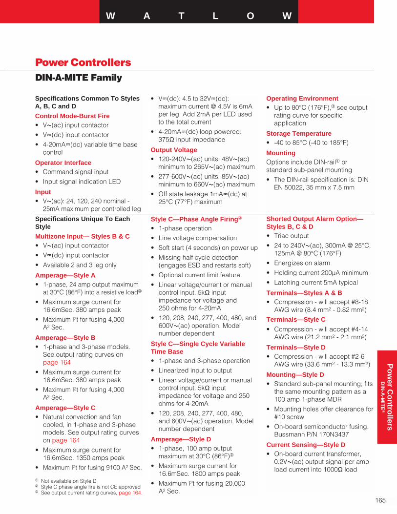
W A T L O W
165
Po
wer C
on
trollers
DIN
-A-M
ITE
®
Power ControllersDIN-A-MITE Family
Specifications Common To StylesA, B, C and D
Control Mode-Burst Fire• VÅ(ac) input contactor
• VÎ(dc) input contactor
• 4-20mAÎ(dc) variable time basecontrol
Operator Interface• Command signal input
• Input signal indication LED
Input• VÅ(ac): 24, 120, 240 nominal -
25mA maximum per controlled leg
a Not available on Style Db Style C phase angle fire is not CE approvedc See output current rating curves, page 164.
Specifications Unique To EachStyle
Multizone Input— Styles B & C• VÅ(ac) input contactor
• VÎ(dc) input contactor
• Available 2 and 3 leg only
Amperage—Style A• 1-phase, 24 amp output maximum
at 30°C (86°F) into a resistive loadc
• Maximum surge current for16.6mSec. 380 amps peak
• Maximum I2t for fusing 4,000 A2 Sec.
Amperage—Style B• 1-phase and 3-phase models.
See output rating curves on page 164
• Maximum surge current for16.6mSec. 380 amps peak
• Maximum I2t for fusing 4,000 A2 Sec.
Amperage—Style C• Natural convection and fan
cooled, in 1-phase and 3-phasemodels. See output rating curveson page 164
• Maximum surge current for16.6mSec. 1350 amps peak
• Maximum I2t for fusing 9100 A2 Sec.
• VÎ(dc): 4.5 to 32VÎ(dc):maximum current @ 4.5V is 6mAper leg. Add 2mA per LED usedto the total current
• 4-20mAÎ(dc) loop powered: 375Ω input impedance
Output Voltage• 120-240VÅ(ac) units: 48VÅ(ac)
minimum to 265VÅ(ac) maximum
• 277-600VÅ(ac) units: 85VÅ(ac)minimum to 660VÅ(ac) maximum
• Off state leakage 1mAÎ(dc) at25°C (77°F) maximum
Style C—Phase Angle Firing2
• 1-phase operation
• Line voltage compensation
• Soft start (4 seconds) on power up
• Missing half cycle detection(engages ESD and restarts soft)
• Optional current limit feature
• Linear voltage/current or manualcontrol input. 5kΩ inputimpedance for voltage and 250 ohms for 4-20mA
• 120, 208, 240, 277, 400, 480, and600VÅ(ac) operation. Modelnumber dependent
Style C—Single Cycle VariableTime Base• 1-phase and 3-phase operation
• Linearized input to output
• Linear voltage/current or manualcontrol input. 5kΩ inputimpedance for voltage and 250ohms for 4-20mA
• 120, 208, 240, 277, 400, 480, and 600VÅ(ac) operation. Modelnumber dependent
Amperage—Style D• 1-phase, 100 amp output
maximum at 30°C (86°F)c
• Maximum surge current for16.6mSec. 1800 amps peak
• Maximum I2t for fusing 20,000 A2 Sec.
Shorted Output Alarm Option—Styles B, C & D• Triac output
• 24 to 240VÅ(ac), 300mA @ 25°C,125mA @ 80°C (176°F)
• Energizes on alarm
• Holding current 200µA minimum
• Latching current 5mA typical
Terminals—Styles A & B• Compression - will accept #8-18
AWG wire (8.4 mm2 - 0.82 mm2)
Terminals—Style C
• Compression - will accept #4-14AWG wire (21.2 mm2 - 2.1 mm2)
Terminals—Style D• Compression - will accept #2-6
AWG wire (33.6 mm2 - 13.3 mm2)
Mounting—Style D• Standard sub-panel mounting; fits
the same mounting pattern as a100 amp 1-phase MDR
• Mounting holes offer clearance for#10 screw
• On-board semiconductor fusing,Bussmann P/N 170N3437
Current Sensing—Style D• On-board current transformer,
0.2VÅ(ac) output signal per ampload current into 1000Ω load
Operating Environment• Up to 80°C (176°F),c see output
rating curve for specificapplication
Storage Temperature• -40 to 85°C (-40 to 185°F)
MountingOptions include DIN-raila orstandard sub-panel mounting
• The DIN-rail specification is: DINEN 50022, 35 mm x 7.5 mm

166
Power ControllersStyle A Ordering Information
To order, complete the code number on the right with the information below.
DIN-A-MITE D A 1 0 - _ _ _ _ - 0 _ _ _
Style A = Solid state power controller
Phase1 = 1-phase, 1 controlled leg
Cooling and Current Rating0 = Natural convection current rating 18A @ 50˚C (122˚F)
(See derating curve for current rating at other temperatures)
Line and Load Voltage02 = 24 to 48VÅ(ac)24 = 100 to 240VÅ(ac)60 = 277 to 600VÅ(ac)
Input TypeC0 = 4.5 to 32VÎ(dc) contactorF0 = 4 to 20mAÎ(dc) proportionalK1 = 22 to 26VÅ(ac) contactorK2 = 100 to 120VÅ(ac) contactorK3 = 200 to 240VÅ(ac) contactor
Manual Language0 = English1 = German2 = Spanish3 = French
Custom parts Designation00 = Standard parts
Recommended Semiconductor Fuses and Fuse KitsSee page 191 for listings and part numbers.
AvailabilityAll combinations available in threeworking days or less.
Style A Dimensions
TopSideFront
F.O.B. Winona, Minnesota
DIN-EN 50022 35 mm by 7.5 mm RailClipping Distance 34.7 mm (1.37 in.) to
Allowance for FastenerMetric = M4
Allowance for #8 Fastener
Grounding Ha(#6)
34 mm(1.34 in.)
11 mm(0.44 in.)
49 mm(1.92 in.)
8(3.
35.3 mm (1.39 in.)
Rail Release Tab(Pull Down)
Zero Electrical Clearance Required
Clearance for Air Flow and Bending Radius
Clearance for Air Flow and Bending Radius
26 mm(1.03 in.)
102 mm(4.00 in.)
40 mm(1.56 in.)
41 mm(1.60 in.)
71 mm(2.80 in.)
94 mm(3.69 in.)
102 mm(4.00 in.)
98 mm(3.87 in.)
50 mm(1.97 in.)
CE approved product. Must useCE filter listed on page 190 forconducted emission.

Power ControllersStyle B
W A T L O W
167
Po
wer C
on
trollers
DIN
-A-M
ITE
®
Ordering Information
To order, complete the code number on the right with the information below.
DIN-A-MITE D B _ _ - _ _ _ _ - _ _ _ _Style B = Solid state power controller
Phase1 = 1-phase, 1 controlled leg2 = 3-phase, 2 controlled legs3 = 3-phase, 3 controlled legs8 = 2 independent zones (Input Type C or K)9 = 3 independent zones (Input Type C or K)
Cooling and Current Rating Per Pole0 = Natural convection standard DIN-rail or panel mount heatsink
Line and Load Voltage02 = 24 to 48VÅ(ac)24 = 120 to 240VÅ(ac)60 = 277 to 600VÅ(ac)
Input Control SignalC0 = 4.5 to 32VÎ(dc) contactorF0 = 4 to 20mAÎ(dc) proportionalK1 = 22 to 26VÅ(ac) contactorK2 = 100 to 120VÅ(ac) contactorK3 = 200 to 240VÅ(ac) contactor
Alarm0 = No alarmS = Shorted SCR alarm (not available with options 8, and 9 above)
User Manual0 = English1 = German2 = Spanish3 = French
Custom Part Numbers00 = Standard partXX = Any letter or number, custom options, labeling, etc.
Recommended Semiconductor Fuses and Fuse KitsSee page 191 for listings and part numbers.
Style B Dimensions
Front Side Top
F.O.B.: Winona, Minnesota
Allowance for #8 Fastener, Metric = M4
Grounding Screw (#6)
Allowance for #8 Fastener, Metric = M4
DIN-EN 50022 35 mm by 7.5 mm RailClipping distance 34.7 mm (1.366 in.)
to 35.3 mm (1.390 in.)
49 mm(1.91 in.)
49 mm(1.92 in.)
83 mm(3.25 in.)
54 mm(2.11 in.)
46 mm(1.81 in.)
38 mm(1.51 in.)
102 mm (4.00 in.) Clearance for Air Flowand Wire Bending Radius
Zero Electrical Clearance Required
102 mm (4.00 in.) Clearance for Air Flow and Wire Bending Radius
Rail Release Tab (Pull Down)
94 mm(3.69 in) 75 mm
(2.97 in.)
26 mm(1.03 in.) 102 mm
(4.00 in.)
40 mm(1.56 in.)
71 mm(2.80 in.)
102 mm(4.00 in.)41 mm
(1.60 in.) 83 mm(3.25 in.)
124 mm(4.88 in.)
AvailabilityAll combinations available in threeworking days or less.
CE approved product. Must useCE filter listed on page 190 forconducted emission.

168
Power ControllersStyle C Ordering Information
To order, complete the code number on the right with the information below:
D C _ _ - _ _ _ _ - _ _ _ _Style C = Zero cross solid state power controller in natural and
forced air cooled versions
Phase
1 = 1-phase, 1 controlled leg2 = 3-phase, 2 controlled legs3 = 3-phase, 3 controlled legs (use with four wire wye)8 = 2 independent zones (Input Type C, K)9 = 3 independent zones (Input Type C, K)Cooling and Current rating Per Leg (see table on left)
0 = Natural convection standard Din-rail or panel heatsink1 = Fan cooled 120VÅ(ac) standard Din-rail or panel heatsink2 = Fan cooled 240VÅ(ac) standard Din-rail or panel heatsink3 = Fan cooled 24VÎ(dc) standard Din-rail or panel heatsinkT = Natural convection through wall or cabinet heatsink (NEMA 4X)Line and Load Voltage
02 = 24 to 48VÅ(ac) (Control C, F, K)24 = 100 to 240VÅ(ac) (Control C, F, K)60 = 277 to 600VÅ(ac) (Control C, F, K)Input Control Signal
C0 = 4.5 to 32VÎ(dc) contactorF0 = 4 to 20mAÎ(dc) proportionalK1 = 22 to 26VÅ(ac) contactorK2 = 100 to 120VÅ(ac) contactorK3 = 200 to 240VÅ(ac) contactorAlarm
0 = No alarmS = Shorted SCR alarm (not available with options 8, and 9 above)Language
0 = English1 = German2 = Spanish3 = FrenchCustom Part Numbers
00 = Standard partXX = Any letter or number, custom options, labeling, etc.Recommended Semiconductor Fuses and Fuse KitsSee pages 191 for listings and part numbers.
F.O.B. Winona, Minnesota
1 0 55A1 T 60A1 (1,2,3) 75A2, 8 0 40A2, 8 T 45A2, 8 (1,2,3) 65A3, 9 0 30A3, 9 T 35A3, 9 (1,2,3) 55A
Phase Cooling Current at 50˚C(122˚F)
Current Rating Table
Note: Allow one fuse and one holder per leg fused. Example, a 3-phase, 2-leg DIN-A-MITE requires two fuses and two holders.
AvailabilityAll combinations available in threeworking days or less.
CE approved product. Must useCE filter listed on page 190 forconducted emission.

W A T L O WP
ow
er Co
ntro
llersD
IN-A
-MIT
E®
Power ControllersStyle C
169
Ordering InformationTo order, complete the code number on the right with the information below:
D C _ _- _ _ _ _ - _ _ _ _Style C = Zero cross and phase-angle fired solid state power
controller in natural and forced air cooled versions.
Phase
1 = 1-phase, 1 controlled leg2 = 3-phase, 2 controlled legs3 = 3-phase, 3 controlled legs (use with four wire wye)Cooling and Current Rating Per Leg (see table on left)
0 = Natural convection standard Din-rail or panel heatsink1 = Fan cooled 120VÅ(ac) standard Din-rail or panel heatsink2 = Fan cooled 240VÅ(ac) standard Din-rail or panel heatsink3 = Fan cooled 24VÎ(dc) standard Din-rail or panel heatsinkT = Natural convection through wall or cabinet heatsink (NEMA 4X)Line and Load Voltage
12 = 100 to 120VÅ(ac) (Control L, P, S)20 = 200 to 208VÅ(ac) (Control L, P, S)24 = 230 to 240VÅ(ac) (Control L, P, S)27 = 277VÅ(ac) (Control L, P, S)40 = 400VÅ(ac) (Control L, P, S)48 = 480VÅ(ac) (Control L, P, S)60 = 600VÅ(ac) (Control L, P, S)Input Control Signal
L (0 to 5) = Phase-angle with current limiting1 (DC1 only, Alarm 0 only, includesone current transformer - Single-phase only)
P (0 to 5) = Phase-angle1 (DC1 only, Alarm 0 only - Single-phase only)S (0 to 5) = Single cycle variable time base(Select one of the following input options for L, P, S (0 to 5))
0 = 4 to 20mA1 = 12 to 20mA (single cycle variable time base only - option ‘S’)2 = 0 to 20mA3 = 0 to 5VÎ(dc) proportional4 = 1 to 5VÎ(dc) proportional5 = 0 to 10VÎ(dc) proportional
Alarm
0 = No alarmS = Shorted SCR alarm (for zero cross models only)H = Open-heater and shorted-SCR alarm (for input control signal options S only)
1-phase, 1 controlled leg3-phase, 2 controlled legs3-phase, 3 controlled legs
Language
0 = English1 = German2 = Spanish3 = FrenchCustom Part Numbers
00 = Standard part10 = 1-second soft start (Control option P, L)XX = Any letter or number, custom options, labeling, etc.
1 Phase angle models are not CE approved for conducted emissions.
CE approved product. Must useCE filter listed on page 190 forconducted emission.
Style C Enhancements
F.O.B.: Winona, Minnesota
Option
• Manual Control Kit for processinput cards (1kΩ potentiometer)order #08-5362 separately.
1 0 55A1 T 60A1 (1,2,3) 75A2 0 40A2 T 45A2 (1,2,3) 65A3 0 30A3 T 35A3 (1,2,3) 55A
Phase Cooling Current at 50˚C(122˚F)
Current Rating Table

170
Power ControllersStyle C
Front
Front Top Panel Cutout
Side Top
Thru-Wall DIN-A-MITE Style Ca
Style C DimensionsWithout Cooling Fan
With Cooling Fan
a With the potential for high thru-wall heatsinktemperatures, application may require atouch-safe shield. See amperage curves onpage 164 for details.
138 mm(5.45 in.)
54 mm (2.11 in.)46 mm (1.81 in.)38 mm (1.51 in.)
1 2 3
4 5 6
48 mm(1.89 in.) Allowance for M4
(#8 Fastener)
Allowance for M4(#8 Fastener)
DIN-EN 5002235 by 7.5 mm rail(clipping distance = 34.7 to 35.3 mm [1.366 to 1.390 in.])
87 mm(3.42 in.)
142 mm (5.59 in.)
131 mm(5.17 in.)
146 mm (5.74 in.) 102 mm (4.0 in.)
Front panel is touch-safe, no clearance is required
102 mm (4.0 in.) clearance for air flow and wire bending radius
102 mm (4.0 in.) clearance for air flow and wire bending radius
150 mm(5.89 in.)
Rail Release Tab(pull down)
44 mm(1.73 in.)
57 mm(2.26 in.)
127 mm(5.00 in.)79 mm
(3.10 in.)
102 mm (4.0 in.) minimum
GroundWireEntry
146 mm(5.74 in.)
83 mm(3.25 in.)
Ground lug
M5 (0.8 by 10 mm) (8)M5 Internal Tooth Lock Washer (8)included
178 mm (7.00 in.)
122 mm (4.81 in.)
PanelOpeningOutline
102 mm (4.0 in.) minimumclearance for air flow (top and bottom)
10 mm (0.4 in.) minimumclearance for air flow (both sides)
1 2 3
4 5 6
(2-8 gauge)
Typical Panel Opening
Heatsink Outline
7.0 mm (0.275 in.)
26.3 mm (1.034 in.)78.8 mm
(3.103 in.)98.1 mm
(3.862 in.)105.1 mm(4.137 in.)
10.8 mm (0.425 in.)
41.3 mm(1.625 in.)
117.5 mm(4.625 in.)
148.6 mm(5.850 in.)
161.9 mm(6.375 in.)
Drill 5.8 mm (0.228 in.) (8)
8.6 mm (0.338 in.) Reference
9.5 mm (0.375 in.) Reference
114 mm(4.50 in.)
57 mm (2.25 in.)outside
(any gauge)
55 mm (2.17 in.)inside
(12 gauge)
Front panel is touch-safe,no clearance is required
Sheet Metal (12 GA)
142 mm (5.59 in.)
131 mm(5.17 in.)
146 mm (5.74 in.) 102 mm (4.0 in.)
Front panel is touch-safe, no clearance is required.
102 mm (4.0 in.) clearance for air flow and wire bending radius
102 mm (4.0 in.) clearance for air flow and wire bending radius
150 mm(5.89 in.)
44 mm(1.73 in.)
57 mm(2.26 in.)
127 mm(5.00 in.)79 mm
(3.10 in.)
102 mm (4.0 in.) minimum
Rail Release Tab(pull down)
182 mm(7.16 in.)

Power ControllersStyle D Ordering Information
To order, complete the code number on the right with the information below:
D D 1 0 - _ _ _ _ - _ _ _ _Style D = Solid state power controller
Phase
1 = 1-phase, 1 controlled legCooling and Current Rating
0 = Natural convection current rating 80A @ 50˚C (122˚F) Line and Load Voltage
02 = 24 to 48VÅ(ac)24 = 100 to 240VÅ(ac)48 = 277 to 480VÅ(ac)60 = 277 to 600VÅ(ac)Input Control Signal
C0 = 4.5 to 32VÎ(dc) contactorF0 = 4 to 20mAÎ(dc) proportionalK1 = 22 to 26VÅ(ac) contactorK2 = 100 to 120VÅ(ac) contactorK3 = 200 to 240VÅ(ac) contactorCurrent Sensing or Alarm
0 = No alarm1 = Load current transformerS = Shorted SCR alarmUser Manual Language
0 = English1 = German2 = Spanish3 = FrenchCustom Options
00 = Standard partsRecommended Semiconductor Fuses
Bussmann part number 170N3437 65 amp® 660VÅ(ac), Watlow part number 0808-0096-0000requires two fuses per Style “D” DIN-A-MITE. These should be replaced in pairs.
W A T L O W
171
Po
wer C
on
trollers
DIN
-A-M
ITE
®
AvailabilityAll combinations available in threeworking days or less.
Style D Dimensions
203 mm(8.0 in.)
203 mm (8.0 in.) Clearance For AirFlow and Bending Radius
203 mm (8.0 in.)203 mm (8.0 in.) Clearance For Air
Flow and Bending Radius
178 mm (7.0 in.)
185 mm(7.28 in.)
13 mm (0.50 in.)
13 m
m (
0.5
in.)
Cle
aran
ceF
or
Air
Flo
w
54 mm(2.13 in.)
13 mm(0.50 in.)
67 mm(2.63 in.)
67 mm(2.63 in.)
61 mm(2.38 in.)
Allowance For #10 Fastener Metric = M5
(9.41 in.)
Grounding Screw9.5 mm (.375 in.) -406 mm (16 in.)
(239 mm)
(66 mm)(2.58 in.)
(64 mm)(250 in.)
SideFootprint Top
F.O.B.: Winona, Minnesota
Same mounting footprint as industry standardmercury displacement relays.
CE approved product. Must useCE filter listed on page 190 forconducted emission.
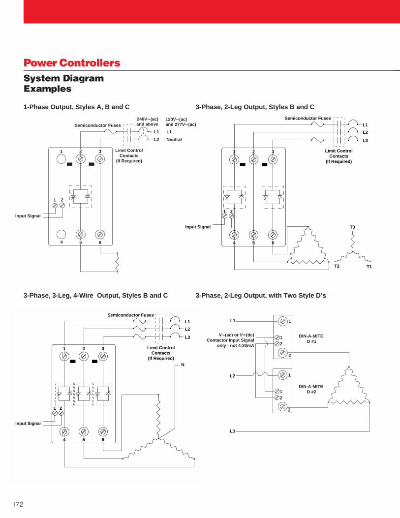
172
Power ControllersSystem DiagramExamples
L1
L2
5
2 Limit ControlContacts
(If Required)
Semiconductor Fuses
6
3
L1
Neutral
Input Signal
1
4
240VÅ(ac)and above
120VÅ(ac)and 277VÅ(ac)
1 2
L2
L1
L3
T1T2
T3
1 2 3
4 5 6
Limit ControlContacts
(If Required)
Semiconductor Fuses
Input Signal
1 2
N
1 2 3
4 5 6
Limit ControlContacts
(If Required)
Semiconductor Fuses
L2
L1
L3
1 2
Input Signal
L1
L2
L3
DIN-A-MITE D #1
DIN-A-MITE D #2
12
12
1
1
2
2
VÅ(ac) or VÎ(dc)Contactor Input Signal
only - not 4-20mA
1-Phase Output, Styles A, B and C 3-Phase, 2-Leg Output, Styles B and C
3-Phase, 3-Leg, 4-Wire Output, Styles B and C 3-Phase, 2-Leg Output, with Two Style D’s

Power ControllersSERIES CZR
W A T L O W
173
Output Voltage
• 24 volt; 24VÅ(ac) min. to 280VÅ(ac) max.
• 480 volt; 48VÅ(ac) min. to530VÅ(ac) max.
• 600 volt; 48VÅ(ac) min. to660VÅ(ac) max. (not available on 18 amp version)
• Off state leakage1mA at 25°C (77°F) max. for600VÅ(ac) models; 10mA at 25°C(77°F) max. for 24 through480VÅ(ac) models
• Holding current: 250mA max.
Output Amperage
• See output rating curve. Ratingsare into a resistive heater load
Output Amperage Rating
The SERIES CZR solid state contactorprovides a low-cost, highly compactand versatile solid state option forcontrolling electric heat. With din-railand back panel mounting standard onevery controller, the CZR allows forsimple and quick installation.
The extensive capabilities of theSERIES CZR include single-phase, 18 to 50 amp zero-cross and randomswitching up to 600VÅ(ac) (seeoutput rating curve). The uniqueintegrated design removes theguesswork associated with selectinga proper heat sink and preciseterminations for the application.
SERIES CZR contactors are availablein Vı(ac/dc) input contactor versions.All configurations are model numberdependent and factory selectable.
The SERIES CZR is reliably backedby a two-year warranty from WatlowWinona.
Performance Capabilities
• Output 18 to 50 amps
• Output voltage up to 660VÅ(ac)
Features and Benefits
DIN-rail or standard panel mount
• Versatile, quick and low-costinstallation
Compact size
• Reduces panel space; less cost
Touch-safe terminals
• Increase safety for installer andoperator
Mercury-free
• Environmentally safe
Faster switching with solid state
• Saves energy and extends heater life
Agency Approvals
• UL® recognized, CSA certified,VDE and CE
• Applications requiring agencyapproval
Back-to-back SCR design
• Rugged design
Specifications
Control Mode
• Zero-cross or random firedcontactor output
Operator Interface
• Command signal input
• Input signal indication LED
Input Command Signal
• Input Type DC1
• Turn on voltage 4VÎ(dc) max.,turn off voltage 1VÎ(dc) min.
• Input current: dc typically 10mA@ 4VÎ(dc),13mA @ 32VÎ(dc)
• Input Type AC1
• 90 to 140Vrms, must turn on at90VÅ(ac), must turn off at10VÅ(ac)
• Input current: 15mA typical @120VÅ(ac)
• Input Type AC2
• 18 to 36VÅ(ac) input, must turnon at 18VÅ(ac), must turn off at10VÅ(ac)
• Input current: 10mA typical @24VÅ(ac)
Model 18 24 34
Maximum Surge Current 625 250 62516.6 mSec
Maximum I2t for fusing 1,620 260 1,620
Model 42 50
Maximum Surge Current 1,000 1,00016.6 mSec
Maximum I2t for fusing 4,150 6,000
Po
wer C
on
trollers
SE
RIE
S C
ZR
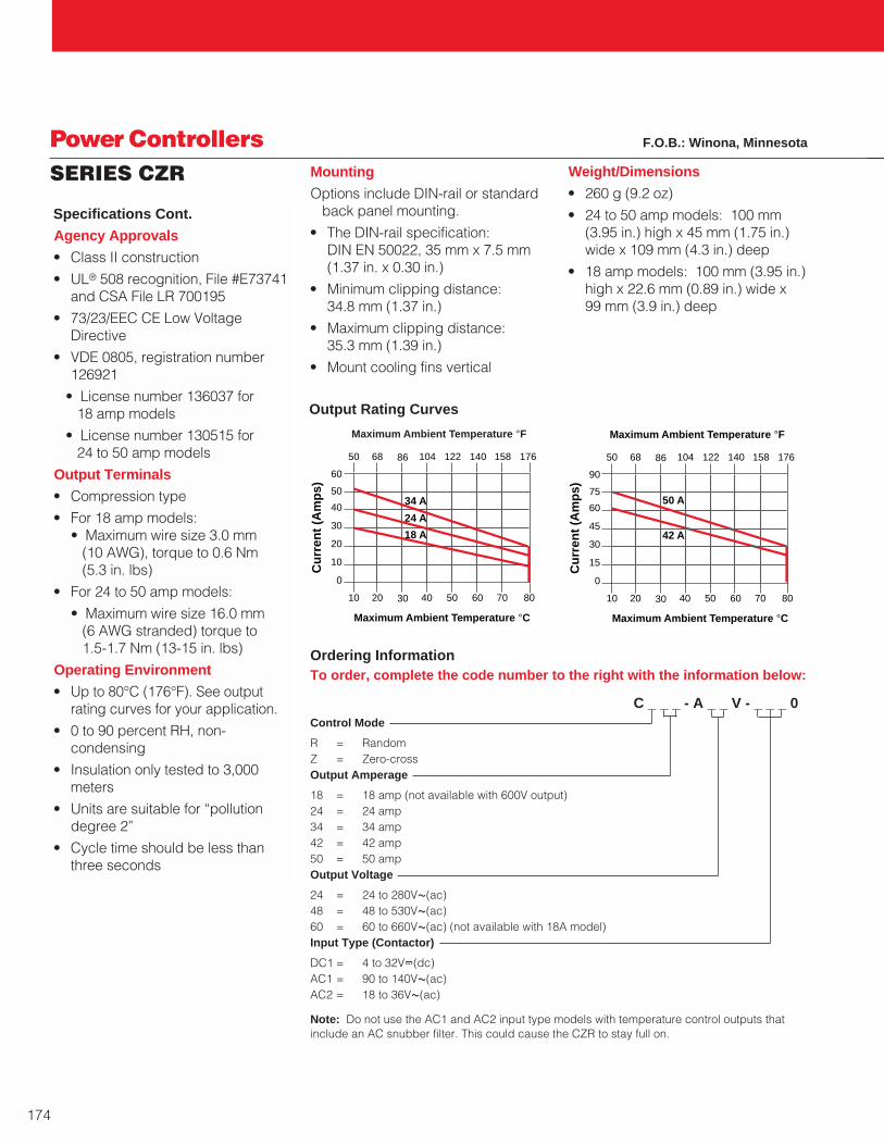
174
Ordering InformationTo order, complete the code number to the right with the information below:
C _ _ _ - A _ _ V - _ _ _ 0Control Mode
R = RandomZ = Zero-crossOutput Amperage
18 = 18 amp (not available with 600V output)24 = 24 amp 34 = 34 amp42 = 42 amp50 = 50 ampOutput Voltage
24 = 24 to 280VÅ(ac)48 = 48 to 530VÅ(ac)60 = 60 to 660VÅ(ac) (not available with 18A model)Input Type (Contactor)
DC1 = 4 to 32VÎ(dc)AC1 = 90 to 140VÅ(ac) AC2 = 18 to 36VÅ(ac)
Power ControllersSERIES CZR
Specifications Cont.
Agency Approvals
• Class II construction
• UL® 508 recognition, File #E73741and CSA File LR 700195
• 73/23/EEC CE Low VoltageDirective
• VDE 0805, registration number126921
• License number 136037 for 18 amp models
• License number 130515 for 24 to 50 amp models
Output Terminals
• Compression type
• For 18 amp models:• Maximum wire size 3.0 mm
(10 AWG), torque to 0.6 Nm (5.3 in. lbs)
• For 24 to 50 amp models:
• Maximum wire size 16.0 mm (6 AWG stranded) torque to 1.5-1.7 Nm (13-15 in. lbs)
Operating Environment
• Up to 80°C (176°F). See outputrating curves for your application.
• 0 to 90 percent RH, non-condensing
• Insulation only tested to 3,000meters
• Units are suitable for “pollutiondegree 2”
• Cycle time should be less thanthree seconds
Mounting
Options include DIN-rail or standardback panel mounting.
• The DIN-rail specification: DIN EN 50022, 35 mm x 7.5 mm(1.37 in. x 0.30 in.)
• Minimum clipping distance: 34.8 mm (1.37 in.)
• Maximum clipping distance: 35.3 mm (1.39 in.)
• Mount cooling fins vertical
60
50
40
30
20
10
0
10 20 30 40 50 60 70 80
Cu
rren
t (A
mp
s)
Maximum Ambient Temperature °C
50 68 86 104 122 140 158 176
Maximum Ambient Temperature °F
24 A
18 A
34 A
90
75
60
45
30
15
0
10 20 30 40 50 60 70 80
Cu
rren
t (A
mp
s)
Maximum Ambient Temperature °C
50 68 86 104 122 140 158 176
Maximum Ambient Temperature °F
42 A
50 A
Weight/Dimensions
• 260 g (9.2 oz)
• 24 to 50 amp models: 100 mm(3.95 in.) high x 45 mm (1.75 in.)wide x 109 mm (4.3 in.) deep
• 18 amp models: 100 mm (3.95 in.)high x 22.6 mm (0.89 in.) wide x 99 mm (3.9 in.) deep
Output Rating Curves
Note: Do not use the AC1 and AC2 input type models with temperature control outputs thatinclude an AC snubber filter. This could cause the CZR to stay full on.
F.O.B.: Winona, Minnesota
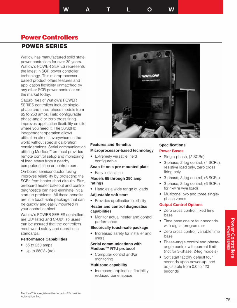
Power Controllers
W A T L O W
175
Po
wer C
on
trollers
PO
WE
R S
ER
IES
POWER SERIES
Watlow has manufactured solid statepower controllers for over 30 years.Watlow’s POWER SERIES representsthe latest in SCR power controllertechnology. This microprocessor-based product offers features andapplication flexibility unmatched byany other SCR power controller onthe market today.
Capabilities of Watlow’s POWERSERIES controllers include single-phase and three-phase models from65 to 250 amps. Field configurablephase-angle or zero cross firingimproves application flexibility on sitewhere you need it. The 50/60Hzindependent operation allowsutilization almost everywhere in theworld without special calibrationconsiderations. Serial communicationutilizing Modbus™ protocol providesremote control setup and monitoringof load status from a nearbycomputer station or control room.
On-board semiconductor fusingimproves reliability by protecting theSCRs from heater short circuits. Plus, on-board heater bakeout and controldiagnostics can help eliminate initialstart up problems. All these benefitsare in a touch-safe package that canbe quickly and easily mounted inyour control cabinet.
Watlow’s POWER SERIES controllersare UL® listed and C-UL®, so userscan be assured that the controllersmeet world safety and operationalstandards.
Performance Capabilities
• 65 to 250 amps
• Up to 660VÅ(ac)
Features and Benefits
Microprocessor-based technology
• Extremely versatile, fieldconfigurable
Snap-fit on a pre-mounted plate
• Easy installation
Models 65 through 250 ampratings
• Handles a wide range of loads
Adjustable soft start
• Provides application flexibility
Heater and control diagnosticscapabilities
• Monitor actual heater and controlperformance
Electrically touch-safe package
• Increased safety for installer andusers
Serial communications withModbus™ RTU protocol
• Computer control and/ormonitoring
Multizone capability
• Increased application flexibility,reduced panel space
Specifications
Power Bases
• Single-phase, (2 SCRs)
• 3-phase, 2-leg control, (4 SCRs),resistive load only, zero crossfiring only
• 3-phase, 3-leg control, (6 SCRs)
• 3-phase, 3-leg control, (6 SCRs)for 4-wire wye loads
• Multizone, two and three single-phase zones
Output Control Options
• Zero cross control, fixed timebase
• Time base one or four secondswith digital programmer
• Zero cross control, variable timebase
• Phase-angle control and phase-angle control with current limit (not for 3-phase, 2-leg models)
• Soft start factory default fourseconds upon power-up, andadjustable from 0.0 to 120seconds
Modbus™ is a registered trademark of SchneiderAutomation, Inc.

176
Power ControllersPOWER SERIES Digital Programmer/Display and
Communications Capabilities
• Programming functions
• Adjust input and output controltype, alarms and soft start, heaterbakeout and current limit prompts
• Monitoring functions
• Display input and output valuesalong with actual output current
• Data retention of digitalprogrammer/display upon powerfailure via nonvolatile memory
Serial Communications
• RS-232 for single drop control
• EIA-485 for single or multidropcontrol
• 32 units maximum can beconnected. With additional 485repeater hardware, up to 247units may be connected
• Isolated
• Modbus™ RTU protocol
• 1200, 2400, 4800, 9600,19200baud rates
Controller Power Supply
• Universal line voltage input range100 to 240VÅ(ac) (+10 percent, -15 percent) at 55VA max
• 50/60Hz ± 5 percent linefrequency independent
• Controller line voltage forelectronic power supply can berun on separate line voltage
Natural Convection and FanCooled Models
• Cabinet venting may be required
• See chart on page 178 for modelsthat include fan cooling
Power Dissipation (Watts)
• Approximately 1.25 watts/ampper controlled leg
Specifications Cont.
• Soft start upon input signalchange, output rate of changeadjustable to limit max rate ofchange from 0.1 to 100 percentper 0.1 second. Factory default10 percent
• Current transformer includedwhen required
• Line voltage compensated(variable time base and phase angle controllers only)
• Standby or non-operational mode
Output Voltage and Current Rating
• 24 to 120VÅ(ac) (+10 percent, -15 percent)
• 200 to 480VÅ(ac) (+10 percent, -15 percent)
• 200 to 600VÅ(ac) (+10 percent, -15 percent)
• 65 through 250 amps per pole,model dependent; see OutputAmperage Chart page 178
• Minimum load 1 amp rms ac
• Maximum leakage current 5mA
Alarms
• Single alarm relay
• Latching or non-latching
• Separate high and low values
• Alarm silencing (inhibit) on powerup for alarm
• Alarm indication LEDs, shortedSCR, open heater
• Electromechanical relay, form Ccontact, software configurable
• Minimum load current 10mA @5VÎ(dc)
• Rated resistive loads: 3 amps @250VÅ(ac) or 30VÎ(dc) max.,inductive load rating 1.5 ampswith a power factor ≥ 0.4 withoutcontact suppression
Heater Bakeout
• For single-phase (phase toneutral) and 3-phase 6 SCR models only (not for 3-phase, 2-leg models)
• Soft start with over current trip,runs until programmed bakeouttime expires, then goes burst orphase-angle firing. Factorydefault of 24 hours
• Adjustable 0 - 9999 minutes withover current trip
• Internal current transformerincluded
Command Signal Input
Analog
• Field selectable linear voltageand current of low and highpoints within 0-20mA and 0-10VÎ(dc)
• Manual control input through frontpanel as a percent power
• Factory default 4-20mA input
• Voltage input impedance 11kΩnominal
• Current input impedance 100Ωnominal
Digital
• On-board digital programmer/display and optional serialcommunications
Retransmit
• Field selectable and scalablewithin 0-20mA, 800Ω maximum or 0-10VÎ(dc), load, 1KΩ minimumload. The default is 4-20mA
• Resolution:
mA ranges = ±5µA nominal
VÎ(dc) = ranges 2.5mV nominal
• Calibration accuracy:
mA ranges = ±20µA
VÎ(dc) ranges = 10mV nominal
• Temperature stability: 100ppm°C

W A T L O W
177
Po
wer C
on
trollers
PO
WE
R S
ER
IES
Power ControllersPOWER SERIES
Specifications Cont.
Isolation
• Command signal to load andline/load to ground 2200VÅ(ac)minimum
• On-board semiconductor fusesprovide SCR protection
Mounting
• Mounts on a removable subplate
• Heat sink fins must be mounted invertical orientation
High Current Terminals
• Touch safe
• 10 mm (0.375 in.) Allen headcompression terminals will accept #6 AWG to 350 MCM wire. Allenwrench adapter (included) for 10 mm (0.375 in.) socket, 6 point only
• Torque to 180 in.-lbs (20.3 Nm)
• Wire strip to 30 mm (1.125 in.)
Controller Terminals
• Touch safe
• 2.5 mm (0.125 in.) blade screw-driver, accepts 12-22 AWG or 2 No. 22-18 AWG wires
• Torque to 8 in.-lbs (0.9 Nm)
• Wire strip to 6 mm (0.24 in.)
Operating Environment
• 50°C (122°F) base rating
• 0 to 60°C (32 to 140°F) fan cooled
• 0 to 65°C (32 to 149°F) naturalconvection cooled
• 0 to 90 percent RH, non-condensing
• Meets EN50178, pollution degreethree
Storage Temperature
• -40 to 85°C (-40 to 185°F)
Shipping Weight
• 10.3 kg (23 lbs)
Agency Approvals
• UL® 508 listed, File #E73741, Vol. three, Sec. two
• C-UL® listed to C22.2 NO. 14
• VDE EN 50178 License 115054
• CE 89/336/EEC (EN61326), ClassA with filter, CE 73/23/EEC (EN50178)
Single-Phase Configuration
This configuration can be purchasedwith any or all the features availableon the POWER SERIES, based on customer preference. It is intendedfor resistive heaters, but can also beused on transformer connectedloads in the phase-angle firing mode.
Three-Phase, Two-LegConfiguration
This configuration is intended forzero cross firing only into a stableresistive heater. Typically, a three-phase delta or ungrounded wyeconnected heater is used and onlytwo of the three VÅ line phases areswitched. The third-phase is a directconnection through a bussbar onboard the POWER SERIES. Heatercurrent monitoring and kVA optionsare available via the heaterdiagnostics option.
Three-Phase, Three LegConfiguration
All POWER SERIES options areavailable with this configuration. It works well with phase-angle firinginto a three-phase, three-wire wye or delta connected heater. In thisconfiguration, the more commonapplications are transformerconnected loads with heatersrequiring a soft start and/or current limiting.
The three-phase, four-wireconfiguration is intended for zerocross firing into a three-phasegrounded wye/star heater (This is aseparate hardware option, modelnumber dependent.)
Single-Phase, MultizoneConfiguration
This configuration is available in twoand three single-phase zones and allthe features of a single-phase unitare available. (Note that there is onlyone alarm relay and all zones in thecontroller must use the same controlmethod.)
Heater Diagnostics
Heater diagnostics may includesome or all of the features thatrequire heater current monitoring,depending on the model selected.Heater current monitoring is only available with heater diagnosticsinstalled on the controller. Thefeatures dependent on heater currentmonitoring are heater bakeout,current limiting, heater kVAmonitoring, retransmit and heatermonitoring alarms such as openheater, heater out of tolerance, loadbalance and shorted SCR detection/error. Heater diagnosticsmust also be installed if you needphase-angle control with current limit.
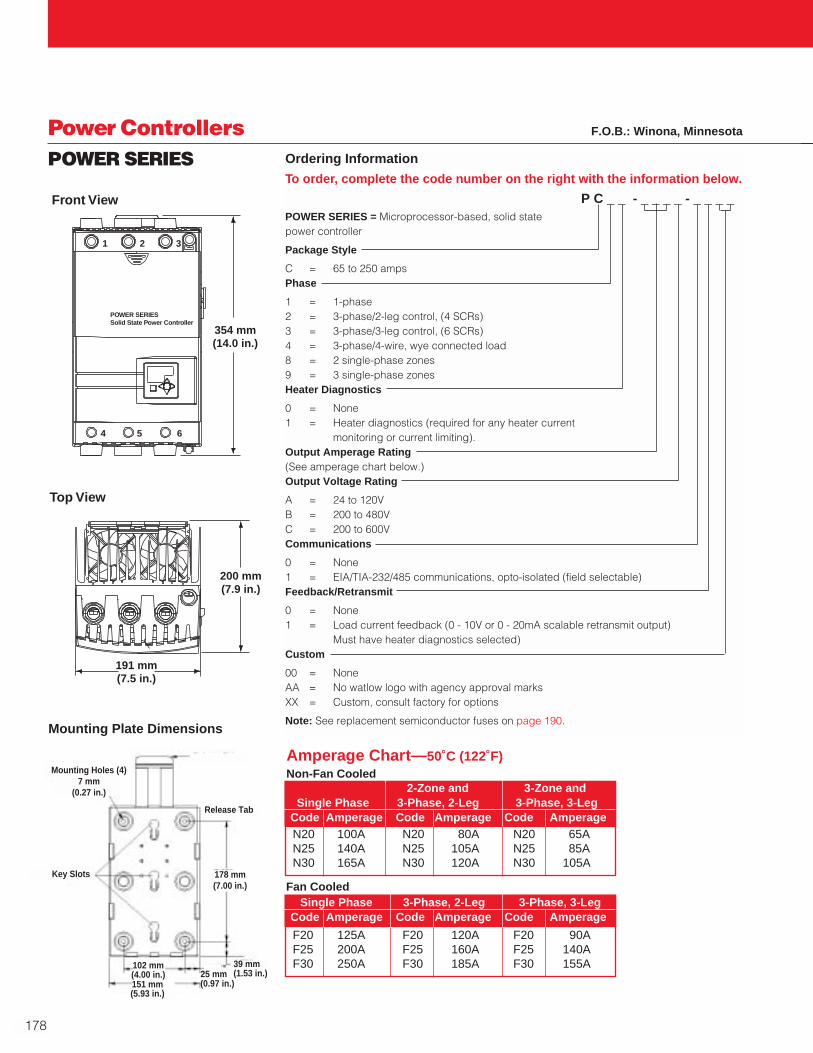
Ordering Information
To order, complete the code number on the right with the information below.
P C _ _ - _ _ _ _ - _ _ _ _POWER SERIES = Microprocessor-based, solid state power controller
Package Style
C = 65 to 250 ampsPhase
1 = 1-phase2 = 3-phase/2-leg control, (4 SCRs)3 = 3-phase/3-leg control, (6 SCRs)4 = 3-phase/4-wire, wye connected load8 = 2 single-phase zones9 = 3 single-phase zonesHeater Diagnostics
0 = None1 = Heater diagnostics (required for any heater current
monitoring or current limiting).Output Amperage Rating(See amperage chart below.)Output Voltage Rating
A = 24 to 120VB = 200 to 480VC = 200 to 600VCommunications
0 = None1 = EIA/TIA-232/485 communications, opto-isolated (field selectable)Feedback/Retransmit
0 = None1 = Load current feedback (0 - 10V or 0 - 20mA scalable retransmit output)
Must have heater diagnostics selected)Custom
00 = NoneAA = No watlow logo with agency approval marksXX = Custom, consult factory for options
Note: See replacement semiconductor fuses on page 190.
178
Power ControllersPOWER SERIES
N20 100A N20 80A N20 65AN25 140A N25 105A N25 85AN30 165A N30 120A N30 105A
2-Zone and 3-Zone andSingle Phase 3-Phase, 2-Leg 3-Phase, 3-Leg
Code Amperage Code Amperage Code Amperage
Amperage Chart—50˚C (122˚F)Non-Fan Cooled
Fan Cooled
F20 125A F20 120A F20 90AF25 200A F25 160A F25 140AF30 250A F30 185A F30 155A
Single Phase 3-Phase, 2-Leg 3-Phase, 3-LegCode Amperage Code Amperage Code Amperage
Release Tab
178 mm(7.00 in.)
39 mm(1.53 in.)25 mm
(0.97 in.)151 mm(5.93 in.)
102 mm(4.00 in.)
Key Slots
Mounting Holes (4)7 mm
(0.27 in.)
Mounting Plate Dimensions
F.O.B.: Winona, Minnesota
200 mm(7.9 in.)
191 mm(7.5 in.)
354 mm(14.0 in.)
Front View
Top View
2 3
4 5 6
POWER SERIESSolid State Power Controller
1
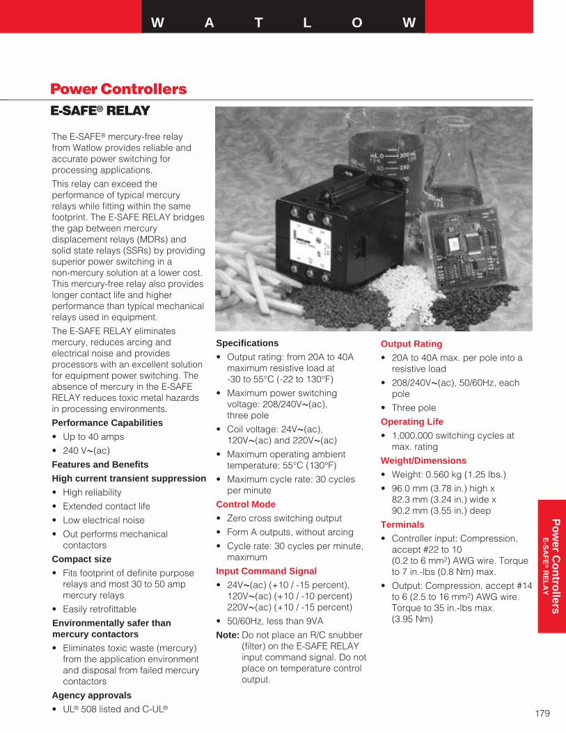
W A T L O W
179
Po
wer C
on
trollers
E-S
AF
E®
RE
LA
Y
Power ControllersE-SAFE® RELAY
The E-SAFE® mercury-free relay from Watlow provides reliable andaccurate power switching for processing applications.
This relay can exceed theperformance of typical mercury relays while fitting within the samefootprint. The E-SAFE RELAY bridgesthe gap between mercurydisplacement relays (MDRs) and solid state relays (SSRs) by providingsuperior power switching in a non-mercury solution at a lower cost.This mercury-free relay also provideslonger contact life and higherperformance than typical mechanicalrelays used in equipment.
The E-SAFE RELAY eliminatesmercury, reduces arcing andelectrical noise and providesprocessors with an excellent solutionfor equipment power switching. Theabsence of mercury in the E-SAFERELAY reduces toxic metal hazardsin processing environments.
Performance Capabilities
• Up to 40 amps
• 240 VÅ(ac)
Features and Benefits
High current transient suppression
• High reliability
• Extended contact life
• Low electrical noise
• Out performs mechanicalcontactors
Compact size
• Fits footprint of definite purposerelays and most 30 to 50 ampmercury relays
• Easily retrofittable
Environmentally safer thanmercury contactors
• Eliminates toxic waste (mercury)from the application environmentand disposal from failed mercurycontactors
Agency approvals
• UL® 508 listed and C-UL®
Specifications
• Output rating: from 20A to 40Amaximum resistive load at -30 to 55°C (-22 to 130°F)
• Maximum power switchingvoltage: 208/240VÅ(ac), three pole
• Coil voltage: 24VÅ(ac),120VÅ(ac) and 220VÅ(ac)
• Maximum operating ambienttemperature: 55°C (130°F)
• Maximum cycle rate: 30 cycles per minute
Control Mode
• Zero cross switching output
• Form A outputs, without arcing
• Cycle rate: 30 cycles per minute,maximum
Input Command Signal
• 24VÅ(ac) (+10 / -15 percent),120VÅ(ac) (+10 / -10 percent)220VÅ(ac) (+10 / -15 percent)
• 50/60Hz, less than 9VA
Note: Do not place an R/C snubber(filter) on the E-SAFE RELAYinput command signal. Do notplace on temperature controloutput.
Output Rating
• 20A to 40A max. per pole into aresistive load
• 208/240VÅ(ac), 50/60Hz, eachpole
• Three pole
Operating Life
• 1,000,000 switching cycles atmax. rating
Weight/Dimensions
• Weight: 0.560 kg (1.25 lbs.)
• 96.0 mm (3.78 in.) high x 82.3 mm (3.24 in.) wide x 90.2 mm (3.55 in.) deep
Terminals
• Controller input: Compression,accept #22 to 10 (0.2 to 6 mm2) AWG wire. Torqueto 7 in.-lbs (0.8 Nm) max.
• Output: Compression, accept #14to 6 (2.5 to 16 mm2) AWG wire.Torque to 35 in.-lbs max. (3.95 Nm)
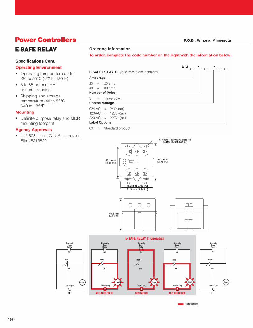
180
Power ControllersE-SAFE RELAY
Specifications Cont.
Operating Environment
• Operating temperature up to -30 to 55°C (-22 to 130°F)
• 5 to 85 percent RH, non-condensing
• Shipping and storagetemperature -40 to 85°C (-40 to 185°F)
Mounting
• Definite purpose relay and MDRmounting footprint
Agency Approvals
• UL® 508 listed, C-UL® approved,File #E213822
Ordering Information
To order, complete the code number on the right with the information below.
E S _ _ - _ _ _ _ - _ _ _ _E-SAFE RELAY = Hybrid zero cross contactor
Amperage
20 = 20 amp40 = 30 ampNumber of Poles
3 = Three poleControl Voltage
024-AC = 24VÅ(ac)120-AC = 120VÅ(ac)220-AC = 220VÅ(ac)Label Options
00 = Standard product
Safety Label
L1 L2 L3
Terminal Label
T1
90.2 mm(3.55 in.)
96.1 mm(3.78 in.)
82.3 mm (3.24 in.)
83.1 mm(3.27 in.)
48.3 mm (1.90 in.)
5.0 mm x 12.0 mm slots 4x(0.197 in. x 0.472 in.)
T3T2
Load
240VÅ(ac)
Off
OFF
240VÅ(ac)
On
ARC ABSORBED
240VÅ(ac)
Off
OPERATING
E-SAFE RELAY In Operation
240VÅ(ac)
On
ARC ABSORBED
Load
240VÅ(ac)
Off
OFF
Off Off On Off Off
Å ÅÅ
Load
Å Å
Load
NormallyOpenRelay
NormallyOpenRelay
NormallyOpenRelay
NormallyOpenRelay
NormallyOpenRelay
LoadLoadLoad
Conduction Path
TriacTriac Triac TriacTriac
F.O.B.: Winona, Minnesota
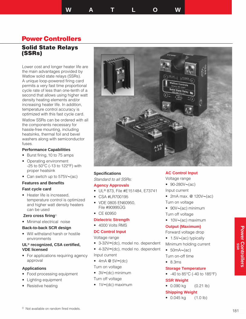
W A T L O W
181
Power ControllersSolid State Relays(SSRs)
Po
wer C
on
trollers
SS
R
Lower cost and longer heater life arethe main advantages provided byWatlow solid state relays (SSRs). A unique loop-powered firing cardpermits a very fast time proportionalcycle rate of less than one-tenth of asecond that allows using higher wattdensity heating elements and/orincreasing heater life. In addition,temperature control accuracy isoptimized with this fast cycle card.Watlow SSRs can be ordered with allthe components necessary forhassle-free mounting, includingheatsinks, thermal foil and bevelwashers along with semiconductorfuses.Performance Capabilities• Burst firing,10 to 75 amps• Operating environment
-25 to 50°C (-13 to 122°F) withproper heatsink
• Can switch up to 575VÅ(ac)
Features and Benefits
Fast cycle card
• Heater life is increased,temperature control is optimizedand higher watt density heaterscan be used
Zero cross firinga
• Minimal electrical noise
Back-to-back SCR design
• Will withstand harsh or hostileenvironments
UL® recognized, CSA certified,VDE licensed
• For applications requiring agencyapproval
Applications• Food processing equipment• Lighting equipment• Resistive heating
SpecificationsStandard to all SSRs:Agency Approvals• UL® 873, File #E151484, E73741• CSA #LR700195• VDE 0805 EN60950,
File #90995ÜG• CE 60950
Dielectric Strength• 4000 Volts RMS
DC Control InputVoltage range• 3-32VÎ(dc), model no. dependent• 4-32VÎ(dc), model no. dependentInput current• 4mA @ 5VÎ(dc)Turn on voltage• 3VÎ(dc) minimumTurn off voltage• 1VÎ(dc) maximum
AC Control InputVoltage range• 90-280VÅ(ac)Input current• 2mA max. @ 120VÅ(ac)Turn on voltage• 90VÅ(ac) minimum
Turn off voltage• 10VÅ(ac) maximum
Output (Maximum)Forward voltage drop• 1.5VÅ(ac) typically
Minimum holding current• 50mAÅ(ac)
Turn on-off time• 8.3ms
Storage Temperature• -40 to 85°C (-40 to 185°F)
SSR Weight• 0.090 kg (0.21 lb)
Shipping Weight• 0.045 kg (1.0 lb)
a Not available on random fired models.
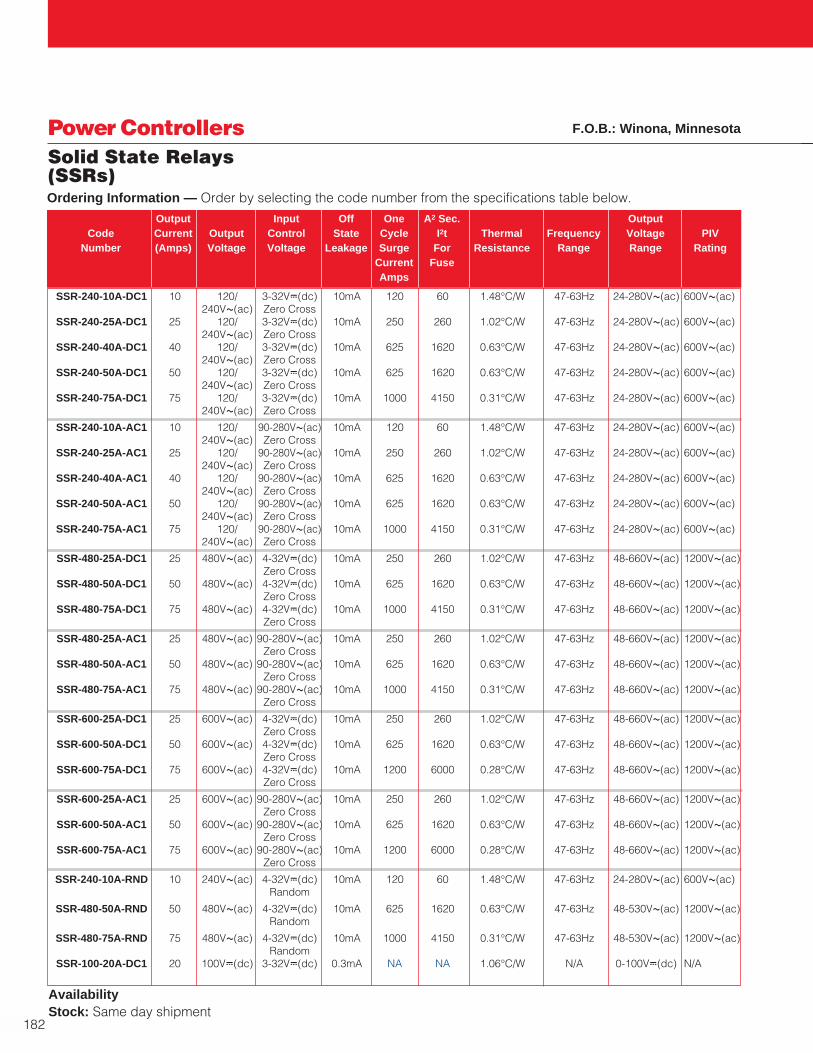
SSR-240-10A-DC1 10 120/ 3-32VÎ(dc) 10mA 120 60 1.48°C/W 47-63Hz 24-280VÅ(ac) 600VÅ(ac)240VÅ(ac) Zero Cross
SSR-240-25A-DC1 25 120/ 3-32VÎ(dc) 10mA 250 260 1.02°C/W 47-63Hz 24-280VÅ(ac) 600VÅ(ac)240VÅ(ac) Zero Cross
SSR-240-40A-DC1 40 120/ 3-32VÎ(dc) 10mA 625 1620 0.63°C/W 47-63Hz 24-280VÅ(ac) 600VÅ(ac)240VÅ(ac) Zero Cross
SSR-240-50A-DC1 50 120/ 3-32VÎ(dc) 10mA 625 1620 0.63°C/W 47-63Hz 24-280VÅ(ac) 600VÅ(ac)240VÅ(ac) Zero Cross
SSR-240-75A-DC1 75 120/ 3-32VÎ(dc) 10mA 1000 4150 0.31°C/W 47-63Hz 24-280VÅ(ac) 600VÅ(ac)240VÅ(ac) Zero Cross
SSR-240-10A-AC1 10 120/ 90-280VÅ(ac) 10mA 120 60 1.48°C/W 47-63Hz 24-280VÅ(ac) 600VÅ(ac)240VÅ(ac) Zero Cross
SSR-240-25A-AC1 25 120/ 90-280VÅ(ac) 10mA 250 260 1.02°C/W 47-63Hz 24-280VÅ(ac) 600VÅ(ac)240VÅ(ac) Zero Cross
SSR-240-40A-AC1 40 120/ 90-280VÅ(ac) 10mA 625 1620 0.63°C/W 47-63Hz 24-280VÅ(ac) 600VÅ(ac)240VÅ(ac) Zero Cross
SSR-240-50A-AC1 50 120/ 90-280VÅ(ac) 10mA 625 1620 0.63°C/W 47-63Hz 24-280VÅ(ac) 600VÅ(ac)240VÅ(ac) Zero Cross
SSR-240-75A-AC1 75 120/ 90-280VÅ(ac) 10mA 1000 4150 0.31°C/W 47-63Hz 24-280VÅ(ac) 600VÅ(ac)240VÅ(ac) Zero Cross
SSR-480-25A-DC1 25 480VÅ(ac) 4-32VÎ(dc) 10mA 250 260 1.02°C/W 47-63Hz 48-660VÅ(ac) 1200VÅ(ac)Zero Cross
SSR-480-50A-DC1 50 480VÅ(ac) 4-32VÎ(dc) 10mA 625 1620 0.63°C/W 47-63Hz 48-660VÅ(ac) 1200VÅ(ac)Zero Cross
SSR-480-75A-DC1 75 480VÅ(ac) 4-32VÎ(dc) 10mA 1000 4150 0.31°C/W 47-63Hz 48-660VÅ(ac) 1200VÅ(ac)Zero Cross
SSR-480-25A-AC1 25 480VÅ(ac) 90-280VÅ(ac) 10mA 250 260 1.02°C/W 47-63Hz 48-660VÅ(ac) 1200VÅ(ac)Zero Cross
SSR-480-50A-AC1 50 480VÅ(ac) 90-280VÅ(ac) 10mA 625 1620 0.63°C/W 47-63Hz 48-660VÅ(ac) 1200VÅ(ac)Zero Cross
SSR-480-75A-AC1 75 480VÅ(ac) 90-280VÅ(ac) 10mA 1000 4150 0.31°C/W 47-63Hz 48-660VÅ(ac) 1200VÅ(ac)Zero Cross
SSR-600-25A-DC1 25 600VÅ(ac) 4-32VÎ(dc) 10mA 250 260 1.02°C/W 47-63Hz 48-660VÅ(ac) 1200VÅ(ac)Zero Cross
SSR-600-50A-DC1 50 600VÅ(ac) 4-32VÎ(dc) 10mA 625 1620 0.63°C/W 47-63Hz 48-660VÅ(ac) 1200VÅ(ac)Zero Cross
SSR-600-75A-DC1 75 600VÅ(ac) 4-32VÎ(dc) 10mA 1200 6000 0.28°C/W 47-63Hz 48-660VÅ(ac) 1200VÅ(ac)Zero Cross
SSR-600-25A-AC1 25 600VÅ(ac) 90-280VÅ(ac) 10mA 250 260 1.02°C/W 47-63Hz 48-660VÅ(ac) 1200VÅ(ac)Zero Cross
SSR-600-50A-AC1 50 600VÅ(ac) 90-280VÅ(ac) 10mA 625 1620 0.63°C/W 47-63Hz 48-660VÅ(ac) 1200VÅ(ac)Zero Cross
SSR-600-75A-AC1 75 600VÅ(ac) 90-280VÅ(ac) 10mA 1200 6000 0.28°C/W 47-63Hz 48-660VÅ(ac) 1200VÅ(ac)Zero Cross
SSR-240-10A-RND 10 240VÅ(ac) 4-32VÎ(dc) 10mA 120 60 1.48°C/W 47-63Hz 24-280VÅ(ac) 600VÅ(ac)Random
SSR-480-50A-RND 50 480VÅ(ac) 4-32VÎ(dc) 10mA 625 1620 0.63°C/W 47-63Hz 48-530VÅ(ac) 1200VÅ(ac)Random
SSR-480-75A-RND 75 480VÅ(ac) 4-32VÎ(dc) 10mA 1000 4150 0.31°C/W 47-63Hz 48-530VÅ(ac) 1200VÅ(ac)Random
SSR-100-20A-DC1 20 100VÎ(dc) 3-32VÎ(dc) 0.3mA NA NA 1.06°C/W N/A 0-100VÎ(dc) N/A
182
Power ControllersSolid State Relays(SSRs)
Availability Stock: Same day shipment
F.O.B.: Winona, Minnesota
Output Input Off One A2 Sec. OutputCode Current Output Control State Cycle I2t Thermal Frequency Voltage PIV
Number (Amps) Voltage Voltage Leakage Surge For Resistance Range Range RatingCurrent FuseAmps
Ordering Information — Order by selecting the code number from the specifications table below.

W A T L O W
183
Power ControllersSolid State Relays(SSRs)
Po
wer C
on
trollers
SS
R
Application Hints
Thermal TransferA thermal foil is provided with eachsolid state relay for mounting on thebase of the relay to improve heattransfer. In addition, two bevelwashers are supplied to provide theproper pressure for the transfer of
100
80
60
40
20
0
Per
cen
t o
f R
ated
Cu
rren
t
With Heatsink
In Free Air
75 100 125 150 175 200Ambient Temperature—°F
Ambient Temperature—°C40 50 65 80
Replacing Contactors or MDRsImprovements in heater life andcontrol accuracy can be anticipatedwith solid state relays operated withrapid cycle times as compared toslower operating electromechanicalrelays or even mercury displacementrelays in some applications. Whenreplacing these types of relays withthe SSR, it is important to considertwo aspects:
1. HeatSolid state devices require a smallvoltage to turn on, which isconsumed as heat (1.5 watts/amp).This heat must be removed from thedevice, and is usually accomplishedby mounting the relay on heatsinks.
2. Failure ModeSolid state devices should last formany years when properly protectedwith voltage and RC suppressors
mounted on appropriate heatsinks,and when fused against the highcurrents caused by electrical shorts.
However, if the unit fails, the mostprobable condition will be a short.Both mechanical relays mentionedabove also have a good probabilityof failing short. In all cases whereuncontrolled full power can causedamage, it is recommended that ahigh limit temperature controller andcontactor be used for protection.
heat. Use two #8-32 screws,15.8 mm(0.625 in.) long to secure the relay tothe heatsink. See the derating curve,Temperature Operating Curve, foroperation without heatsinks.
Thermocouple
Heater
Mounted Current
Transformer
0 and 5VÎ(dc)on-off
RelayContactor
SolidStateRelayD.C.Temp
ControlOpenCollector
L2
L1
- +
SDAShorted SSRDetector
Single Phase—SDASystem Diagrams
Shorted SSR Alarm—SDAThe most prevalent concern whenusing solid state relays is thepossibility of a relay failing in ashorted condition. With this in mind,Watlow has designed a costeffective “Shorted SSR Alarm” SDA.
The device monitors the output(current through the heater) andactivates a triac (alarm) if there is no
Temp Control
With Loop Powered Board
4-20 mAÎ(dc)Output
SBL
DCSSR
+ -
FuseL1
L2
Heater
Single-Phase—SBL4-20mA loop powered firing card fordirect mounting on a dc solid staterelay. Can be used in three-phasemode with two dc input and zerocross solid state relays (SSR).
Single-Phase—AT and BTRequires external power switchingtransformer. Consult factory for partnumber and voltage required. ATrequires a VÎ(dc) input, randomfired output SSR. BT requires VÎ(dc)input, zero cross output SSR.
command signal from thetemperature controller. The triac can be wired to a bell, orto a normally closed latching relayto remove power to the heater.
SBL Burst firing 4-20mA only 08-5399loop powered card for dc input relays only
SDA Shorted SSR alarm 08-5386for dc input relays only
AT Single-phase, phase- 08-5422angle firing
BT Single-phase variable 08-5406time base, single cycle,burst firing, 4-20mA input
SSR CodeCard Description No.
Note: This rating curve applies only to 10 and25 amp SSRs. 40 through 75 amp SSRsshould not exceed a seven amp load withoutusing a heatsink.
Temperature Operating Curve
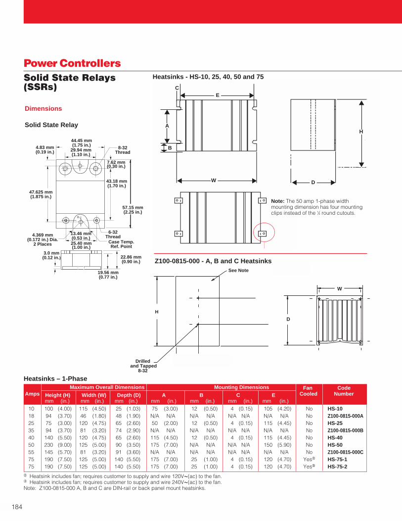
184
Power ControllersSolid State Relays(SSRs)
Heatsinks - HS-10, 25, 40, 50 and 75
D
B
A
EC
W D
AH
Heatsinks – 1-Phase
b Heatsink includes fan; requires customer to supply and wire 120VÅ(ac) to the fan.c Heatsink includes fan; requires customer to supply and wire 240VÅ(ac) to the fan.Note: Z100-0815-000 A, B and C are DIN-rail or back panel mount heatsinks.
4.83 mm(0.19 in.)
44.45 mm(1.75 in.)
29.94 mm(1.10 in.)
8-32Thread
57.15 mm(2.25 in.)
7.62 mm(0.30 in.)
6-32Thread
Case Temp.Ref. Point
19.56 mm(0.77 in.)
22.86 mm(0.90 in.)
3.0 mm(0.12 in.)
4.369 mm(0.172 in.) Dia.
2 Places
47.625 mm(1.875 in.)
13.46 mm(0.53 in.)25.40 mm(1.00 in.)
43.18 mm(1.70 in.)
Solid State Relay
Dimensions
10 100 (4.00) 115 (4.50) 25 (1.03) 75 (3.00) 12 (0.50) 4 (0.15) 105 (4.20) No HS-1018 94 (3.70) 46 (1.80) 48 (1.90) N/A N/A N/A N/A N/A N/A N/A N/A No Z100-0815-000A25 75 (3.00) 120 (4.75) 65 (2.60) 50 (2.00) 12 (0.50) 4 (0.15) 115 (4.45) No HS-2535 94 (3.70) 81 (3.20) 74 (2.90) N/A N/A N/A N/A N/A N/A N/A N/A No Z100-0815-000B40 140 (5.50) 120 (4.75) 65 (2.60) 115 (4.50) 12 (0.50) 4 (0.15) 115 (4.45) No HS-4050 230 (9.00) 125 (5.00) 90 (3.50) 175 (7.00) N/A N/A N/A N/A 150 (5.90) No HS-5055 145 (5.70) 81 (3.20) 91 (3.60) N/A N/A N/A N/A N/A N/A N/A N/A No Z100-0815-000C75 190 (7.50) 125 (5.00) 140 (5.50) 175 (7.00) 25 (1.00) 4 (0.15) 120 (4.70) Yes2 HS-75-175 190 (7.50) 125 (5.00) 140 (5.50) 175 (7.00) 25 (1.00) 4 (0.15) 120 (4.70) Yes3 HS-75-2
Maximum Overall Dimensions Mounting Dimensions Fan CodeAmps Height (H) Width (W) Depth (D) A B C E Cooled Number
mm (in.) mm (in.) mm (in.) mm (in.) mm (in.) mm (in.) mm (in.)
Note: The 50 amp 1-phase width mounting dimension has four mounting clips instead of the 1⁄2 round cutouts.
H
See Note
Drilled and Tapped
8-32
W
D
Z100-0815-000 - A, B and C Heatsinks

W A T L O W
185
Po
wer C
on
trollers
QP
AC
Power ControllersQPAC SCRs
Watlow’s modular QPAC SERIES SCRpower controller features plug-inflexibility with ratings from 150 to1000 amps in 1-phase, 3-phase, 2-leg and 3-phase, 3-leg. A varietyof transformers from 120VÅ(ac) to575VÅ(ac), along with 50/60Hzoperation, enables the QPAC tooperate virtually anywhere in theworld. Firing modes are defined byplug-in cards that set the QPAC for:
• Burst fire variable time base
• Phase-angle operation
• Burst fire firing to act as a solidstate contactor
Models are available with a widevariety of options. High speedsemiconductor fuses are included toprotect the SCR from highercurrents. This modular approach,using a standard base and plug-intransformers and control cards,allows quick shipment of a powercontroller specifically tailored to aparticular application.
Performance Capabilities• Available in ratings from
150 to 1000 amps
• Ambient operating temperatures 0 to 50°C (32 to 122°F)
Features and Benefits
Completely modular powercontroller
• Delivers application flexibility witha variety of plug-in transformersand control cards
Available in 150 to 1000 amp ratings
• Provides appropriate powerswitching for small and large loads
Burst firing, solid state contactorand phase-angle firing modes
• Meets most applicationrequirements
High speed semiconductor fusesand RC snubbers
• Protects the SCR from voltage orcurrent surges or spikes
High capacity heatsinks for 50˚C (122˚F) ambient operation
• Allows using full power rating inindustrial applications
Open heater or shorted SCRdetector option
• On burst fire models, providesdiagnostic capability
Standard models up to 300 ampsUL®508 listed and C-UL®
• For applications requiring agencyapprovals
QPAC
Signal Contactor—ac or dc, ProportionalVoltage or Current
Burst Fired150 to 1000 Amps
Phase-Angle Fired150 to 1000 AmpsWith or W/OCurrent Limit
OR
186
Power ControllersQPAC SCRs
Specifications
Operation
Modular control base with plug-incard and transformer• Plug-in control cards
Solid state contactor, ac or dc input
Burst fire control, fixed or variable time base
Phase-angle fire control with soft start
• Phase-angle control with soft startand current limiting
• Plug-in transformers (50/60Hz)
• 120, 208, 240, 380, 415, 480, 575VÅ(ac) operation
Power bases• Single-phase (Q01),
1 pair of SCRs
• Three-phase (Q32), 2-leg control,2 pair SCRs. Resistive load only,burst firing only.
• Three-phase (Q33), three pairhybrid SCRs/diodes.Recommended for phase-angleonly with balanced load.
Agency Approvals• UL® 508 and C-UL® Listed, File
#E73741
Control Card Inputs
(CA) Solid state contactor, AC input• 120VÅ(ac) @ 30mA minimum
• Ac signal input sources (i.e.,triacs or mechanical relay outputswith noise suppression) requirecustomer supplied resistorsacross the power controller accommand signal input terminals to prevent false firing.
24VÅ(ac) input, 200Ω/10 wattstypical;
120VÅ(ac) input, 1kΩ/25 wattstypical;
240VÅ(ac) input, two 1kΩ/25watts in series typical
(CD) Solid state contactor, DC input• On, 4-10VÎ(dc); off, 0.5VÎ(dc)
• Built-in noise reduction network
(BF) Burst firing control fixed timebase• Process input factory set
@ 4-20mAÎ(dc)
• Input impedance 250Ω(clip resistor for 5kΩ voltageinput), or manual control input
• Time base four seconds (clip resistor for one sec)
(BV) Burst firing control, variabletime base• Process input factory set
@ 4-20mAÎ(dc)
• Input impedance 250Ω(clip resistor for 5kΩ voltageinput), or manual control input
(AF) Phase-angle control• Process input factory set
@ 4-20mAÎ(dc)
• Input impedance 250Ω (clipresistor for 5kΩ voltage input), ormanual control input
• Soft start approximately sixseconds upon power-up, one second upon set pointchange
(AL) Phase-angle control withcurrent limit• Process input factory set
@ 4-20mAÎ(dc)
• Input impedance 250Ω (clipresistor for 5kΩ voltage input), ormanual control input
• Soft start approximately 10seconds upon power-up, onesecond upon set point change
• Current transformer included
Open Heater/Shorted SCRDetector• Triac output
• 24 to 240VÅ(ac), 300mA @ 25°C,125mA @ 80°C
• Energizes on alarm
• Holding current 200µA minimum
• Latching current 5mA typical
Outputs• 120VÅ(ac) through 575VÅ(ac)
• One, two, or three leg
• 150 through 1000 amps per leg
Line Voltage/Power• 50/60Hz ac line frequency
• Voltage: ±10 percent, 120, 208,240, 277, 380, 415, 480, 575VÅ(ac)
Line Voltage Compensation• 10 percent ∆ in line, 2 percent
∆ in load in the 30 percent to 70 percent power region (AF, ALand BV)
Power Dissipation (Watts)• 1.5 watts/amps per controlled leg
Isolation• Command signal to load
1250VÅ(ac) minimum
Linearity• Within 2 percent, 30 to 70 percent
power region (All units except CA & CD)
Off-State Leakage Current• 20mA @ 480VÅ(ac)
SCR Protection• Semiconductor fuses provided
dv/dt 200V/µsec minimum
• MOV1 and RC snubber networkstandard
• (Q32) 3rd leg fuse kit may beused, but not required, with 3-phase, 2-leg models
Mounting• Heatsink fins must be mounted in
vertical orientation

W A T L O W
187
Po
wer C
on
trollers
QP
AC
Power ControllersQPAC SCRs Ordering Information
To order, complete the code number to the right with the information below:Q _ _ - _ _ _ - _ _ _ - _ _ _
QPAC = Modular power controller; phase-angle, burst or solid state contactor with fuse(s) and holder(s) included.Phase
01 = Single-phase32 = 3-phase,-2 leg (optional 3rd leg fuse kit extra.)33 = 3-phase, 3-legOperating and Output Voltage
12 = 120VÅ(ac)20 = 208VÅ(ac)24 = 240VÅ(ac)27 = 277VÅ(ac)38 = 380VÅ(ac)41 = 415VÅ(ac)48 = 480VÅ(ac)57 = 575VÅ(ac)Cooling Fan Voltage2
Customer to supply wiring and hook-up.1 = 120VÅ(ac)2 = 240VÅ(ac)Output Current (Amps)
150 = 150 amps200 = 200 amps300 = 300 amps400 = 400 amps500 = 500 amps600 = 600 amps800 = 800 amps01K = 1000 ampsNote: See POWER SERIES and DIN-A-MITE® equivalent products on pages 168 and 175 for 30 through 100 amps.Input Control Card
CA = Solid state ac input (08-5285) contactorCD = Solid state dc input (08-5286) contactorBF = Burst fired, fixed time base (08-5289) 4-20mABV = Burst fired, variable time base (08-5342) 4-20mAAF = Phase-angle fired, not available on Q32 (08-5288) 4-20mAAL = Phase-angle fired w/current limit, not available on Q32 (08-5411) 4-20mA;
includes one current transformer. Add second CT for 3-phase, 3-leg. AL models 75 amps and above require one interstage transformer.
Open Heater/Shorted SCR Detector34
0 = None1 = Single-phase operation2 = Three-phase operation
AvailabilityShipment within five working days on models up through 300 amps.Beyond 300 amps consult the factory.
a MOV comes only on Q33 (3-phase, 3-leg).2 All cooling fans rated @ 20 watts each,
must be wired by customer.
4 Included one current transformer for 1-phase and two current transformers for 3-phase. Models 150 amps and aboverequire one interstage transformer.
Controller Weights
Specifications Cont.
Operating Environment• 0 to 50°C (32 to 122°F)
• 0 to 90 percent RH, non-condensing
Storage Temperature• -40 to 85°C (-40 to 185°F)
Options
• Manual Control Kit for processinput cards (1kΩ potentiometer)order #08-5362 separately
F.O.B.: Winona, Minnesota
150 6.8 (15) 16.3 (36) 22.7 (50)200 6.8 (15) 16.3 (36) 22.7 (50)300 6.8 (15) 16.3 (36) 22.7 (50)
400-600 19.9 (44) 38.5 (85) 45.4 (100)800-1000 22.2 (49) 54.4 (120) 61.2 (135)
1Ø 3Ø, 2-leg 3Ø, 3-wireQ01 Q32 Q33
Amps kg (lbs) kg (lbs) kg (lbs)
3 The open heater/shorted SCR detector isfor burst fire operation only.
Note
• The Q32 and Q33 models are50/60Hz line frequencydependent. Specify applicationline frequency when ordering forproper calibration.

150 200 Triple 0 100 (4) 4 to 3/0 All models O/B 16-0008200 250 250 MCM 115 (4.5) 6 to 350 MCM All models O/B 16-0045300 400 500 MCM 205 (8) 4 to 500 MCM All models O/B 16-0073400 500 Dual 250 MCM 380 (15) 2 to 600 MCM All models O/B 400A-0004-0286-0400500 600 Dual 350 MCM 380 (15) 2 to 600 MCM All models O/B 500-0004-0286-0500600 800 Dual 500 MCM 380 (15) 2 to 600 MCM All models O/B 600-0004-0286-0600800 1000 Quad 250 MCM 380 (15) 2 to 600 MCM All models O/B 800-0004-0286-0800
1000 1250 Quad 350 MCM 380 (15) 2 to 600 MCM All models O/B 1000-0004-0286-1000
188
Power ControllersQPAC SCRs
Ca 150 330 (13) 175 (6.9) 255 (10) 6.8 (15)Ca 200 330 (13) 175 (6.9) 255 (10) 6.8 (15)Ca 300 330 (13) 175 (6.9) 255 (10) 6.8 (15)Ea 400-600 685 (27) 430 (17) 300 (11.7) 19.9 (44)Ea 800-1000 685 (27) 430 (17) 340 (13.3) 22.2 (49)
Amps Fuse Recommended Bending Lugs Phase Fuse CurrentRating Wire Size Radius Accept Code Mounting Transformer
mm (in.) Wire No.
Note: A circuit breaker (or dis-connect) is required in additionto, and at least of the same ratingas the semiconductor fuses. Fusemounting for those controllerswith external (EXT) fuses willrequire space near the terminalblock. The space for the fuse willdepend upon the current rating.On board fuses (O/B) do notrequire extra fuse space. Wherethird-leg fusing is selected,additional space is required. On575VÅ(ac) models the fuses aremounted external to the QPAC.
Q01 Q32
Q33
Note: Style D eliminated and replaced with Style E.
Case Styles
Style C Style E
a Includes fan cooling
Style Amps Height (H) Width (W) Depth (D) Weightmm (in.) mm (in.) mm (in.) kg (lbs)
Ca 150 330 (13) 355 (14) 260 (10.25) 16.3 (36)Ca 200 330 (13) 355 (14) 260 (10.25) 16.3 (36)Ca 300 330 (13) 355 (14) 260 (10.25) 16.3 (36)Ea 400-600 685 (27) 535 (21) 300 (11.7) 38.5 (85)Ea 800-1000 840 (33) 535 (21) 340 (13.3) 54.4 (120)
Style Amps Height (H) Width (W) Depth (D) Weightmm (in.) mm (in.) mm (in.) kg (lbs)
Style Amps Height (H) Width (W) Depth (D) Weightmm (in.) mm (in.) mm (in.) kg (lbs)
Ca 150 330 (13) 525 (20.7) 260 (10.25) 23 (50)Ca 200 330 (13) 525 (20.7) 260 (10.25) 23 (50)Ca 300 330 (13) 525 (20.7) 260 (10.25) 23 (50)Ea 400-600 840 (33) 685 (27) 300 (11.7) 45.4 (100)Ea 800-1000 840 (33) 685 (27) 340 (13.3) 61.2 (135)
QPAC Replacement SCRs and DiodesSee page 189
Current TransformersSee page 189
Third Leg (Semiconductor) Fuse KitsSee page 192
Semiconductor Replacement FusesSee page 192
Wiring Information
a Includes fan cooling
a Includes fan cooling

W A T L O W
189
Power ControllersAccessories
F.O.B.: Winona, Minnesota
Po
wer C
on
trollers
Accesso
ries
F.O.B.: Winona, Minnesota
The following accessories andreplacement parts are available toenhance the application and serviceof Watlow power controllers.
To order, simply identify thespecification of the desiredcomponent and use its part number.
Consult your Watlow representativefor availability.
Part No. Current Ratio
Note: An interstage transformer (code no. 16-0176) is required with anycurrent transformer rated 75 amps or above.a Supercedes code numbers 16-0230,
16-0231, 16-0232, 16-0233.b Use 2-wire passes through the current
transformer 16-0008 for 75 ampapplications.
Current Transformers
QPAC Part Numbers
Amps Q01 Q32 Q33
QPAC Replacement SCRs and Diodes
d All units (except Q33) require two SCRs (1 pair) per controlled leg.Q33 (150 amp and above) uses one replaceable diode and oneSCR per controlled leg.
Current Transformer16-0230 (See 16-0246)16-0231 (See 16-0246)16-0232 (See 16-0246)16-0233 (See 16-0246)
16-0246aa 20 amp: 20mAto
50 amp: 50mA
16-0008bb 75 amp: 5 amp16-0044 100 amp: 5 amp16-0072 125 amp: 5 amp16-0008 150 amp: 5 amp16-0045 200 amp: 5 amp16-0073 300 amp: 5 amp
0004-0286-0400 400 amp: 5 amp0004-0286-0500 500 amp: 5 amp0004-0286-0600 600 amp: 5 amp0004-0286-0800 800 amp: 5 amp0004-0286-1000 1000 amp: 5 amp
Interstage Transformer16-0176 5 amp: 20mA
150 amp 18-5052 18-5052 18-5052dd
200 amp 18-5052 18-5052 18-5052dd
300 amp 18-5052 18-5052 18-5052dd
400-600 amp 18-5214 18-5214 18-5214dd
800 amp 18-5215 18-5215 18-5215dd
1000 amp 18-5216 18-5216 18-5215dd
Diodes150 amp 18-1044dd
200 amp 18-1044dd
300 amp 18-1044dd
400-600 amp 18-1064dd
800 amp 18-1068dd
1000 amp 18-1068dd
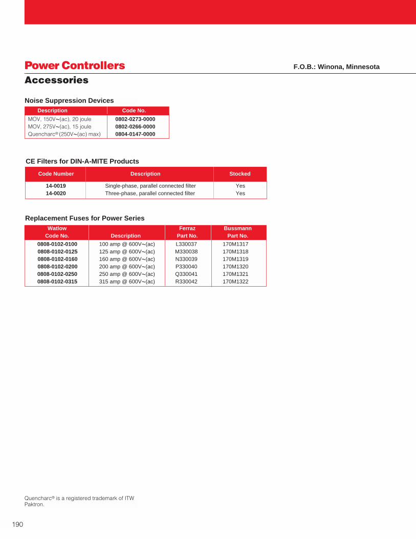
190
Power ControllersAccessories
F.O.B.: Winona, Minnesota
0808-0102-0100 100 amp @ 600VÅ(ac) L330037 170M13170808-0102-0125 125 amp @ 600VÅ(ac) M330038 170M13180808-0102-0160 160 amp @ 600VÅ(ac) N330039 170M13190808-0102-0200 200 amp @ 600VÅ(ac) P330040 170M13200808-0102-0250 250 amp @ 600VÅ(ac) Q330041 170M13210808-0102-0315 315 amp @ 600VÅ(ac) R330042 170M1322
Watlow Ferraz BussmannCode No. Description Part No. Part No.
Replacement Fuses for Power Series
MOV, 150VÅ(ac), 20 joule 0802-0273-0000MOV, 275VÅ(ac), 15 joule 0802-0266-0000Quencharc® (250VÅ(ac) max) 0804-0147-0000
Description Code No.
Noise Suppression Devices
Quencharc® is a registered trademark of ITWPaktron.
14-0019 Single-phase, parallel connected filter Yes14-0020 Three-phase, parallel connected filter Yes
Code Number Description Stocked
CE Filters for DIN-A-MITE Products

W A T L O W
191
Power ControllersAccessories
F.O.B.: Winona, Minnesota
12 600 17-8012 H330011 FWC-12A10F 17-5110
20 600 17-8020 K330013 FWC-20A10F 17-5110
25 600 17-8025 L330014 FWC-25A10F 17-5110
32 700 17-8030 M330015 FWP-32A14F 17-5114
40 700 17-8040 A93909 FWP-40A14F 17-5114
50 700 17-8050 B093910 FWP-50A14F 17-5114
63 700 17-8063 T094823 FWP-63A22F 17-5122
65 660 0808-0096-0000 N /A 170N3437 See Note 1
80 700 17-8080 A94829 FWP-80A22F 17-5122
100 700 17-8100 N/A FWP-100A22F 17-5122
Po
wer C
on
trollers
Accesso
ries
F.O.B.: Winona, Minnesota
Semiconductor Fuses for DIN-A-MITE® Power Controllers
Styles A, B, C and D…Can Also BeUsed For VPAC, SSRs and CZR’s
Semiconductor Fuse SelectionGuidelinesThe following steps will help youidentify the proper semiconductorfuse for your application.
1. Semiconductor fuses are requiredfor SCR protection.
2. In North America, semiconductorfuses are considered a specialtyfuse and not yet approved forbranch circuit or cable protection.
3. All fuses should be rated at 125 percent of the connectedload (or the next standard fuserating above 125 percent). Do notexceed 160 percent of the DIN-A-MITE®.
For example:
A 30 amp Style B DIN-A-MITE witha 20 amp connected load shoulduse a 25 amp semiconductorfuse.
4. Due to special applications,cooler ambient temperatures,small loads, etc., the connectedload should be the determiningfactor—although thesemiconductor fuse I2t rating mustnot exceed the SCR I2trequirement.
The following charts may bemodified following the above guidelines.
WD
H
Dimensions
Fuse Amp Fuse Voltage Watlow Ferraz Bussman Equiv. WatlowRating Rating Fuse Part No. Fuse Part No. Fuse Part No. Holder Part No.
DIN-Rail Mount Semiconductor Fuses and Holders
17-5110 81 (3.18) 18 (0.71) 59 (2.32) 10 X 38 17-5114 111 (4.36) 26 (1.02) 77 (3.03) 14 X 51 17-5122 128 (5.04) 35 (1.38) 77 (3.03) 22 X 58
Holder Part No. Height Width Depth Fuse Typemm (in.) mm (in.) mm (in.) (mm)
DIN-Rail Mount Fuse Holders Maximum Dimensions
Note 1: Replacement fuse for DIN-A-MITE Style DNote 2: On part number 17-8030 the fuse is a 32 ampere fuse

20 amp @ 700VÅ(ac) 17-7071 All Q01 30 amp - 2 fuses required
30 amp @ 700VÅ(ac) 17-7072 All Q01 50 amp - 2 fuses required
40 amp @ 700VÅ(ac) 17-7007 All Q32 and Q33 30 amp70 amp @ 700VÅ(ac) 17-7010 All Q32 and Q33 50 amp
100 amp @ 700VÅ(ac) 17-7012 All 75 amp, 600V QPACs
100 amp @ 500VÅ(ac) 17-7050 All 75 amp, 480V or less QPACs
125 amp @ 500VÅ(ac) 17-7051 All 100 amp, 480V or less QPACs
200 amp @ 500VÅ(ac) 17-7053 All 150 amp, 480V or less QPACs
250 amp @ 500VÅ(ac) 17-7054 All 200 amp, 480V or less QPACs
400 amp @ 500VÅ(ac) 17-7056 All 300 amp, 480V or less QPACs
500 amp @ 500VÅ(ac) 17-7057 All 400 amp, 480V or less QPACs
600 amp @ 500VÅ(ac) 17-7058 All 500 amp, 480V or less QPACs
800 amp @ 500VÅ(ac) 17-7059 All 600 amp, 480V or less QPACs
1,000 amp @ 700VÅ(ac) 17-7082 All 800 amp QPACs
1,250 amp @ 700VÅ(ac) 17-7081 All 1,000 amp QPACs
192
Power ControllersAccessories
Fuse Block Dimensions
Description Part No. QPAC Models Used On
QPAC Semiconductor Fuses
A
B
C31.75 mm(1.25 in.)
44.45 mm(1.75 in.)
One 15 amp fuse, one 1-phase holder 3LF-10 85 (3.25) 110 (4.25) 120 (4.75)One 25 amp fuse, one 1-phase holder 3LF-20 85 (3.25) 110 (4.25) 120 (4.75)One 40 amp fuse, one 1-phase holder 3LF-30 110 (4.25) 135 (5.25) 145 (5.75)One 70 amp fuse, one 1-phase holder 3LF-50 110 (4.25) 135 (5.25) 145 (5.75)One 100 amp fuse, one 1-phase holder 3LF-75 90 (3.50) 115 (4.50) 125 (5.00)One 125 amp fuse, one 1-phase holder 3LF-100 90 (3.50) 115 (4.50) 125 (5.00)
One 200 amp fuse, one 1-phase holder 3LF-150 90 (3.50) 115 (4.50) 125 (5.00)One 250 amp fuse, one 1-phase holder 3LF-200 85 (3.28) 20 (0.76) 150 (6.00)One 400 amp fuse, one 1-phase holder 3LF-300 85 (3.28) 20 (0.76) 150 (6.00)One 500 amp fuse, one 1-phase holder 3LF-400 85 (3.28) 20 (0.76) 150 (6.00)One 600 amp fuse, one 1-phase holder 3LF-500 85 (3.28) 20 (0.76) 150 (6.00)
One 800 amp fuse, one 1-phase holder 3LF-600 Consult factoryOne 1000 amp fuse, one 1-phase holder 3LF-800 Consult factoryOne 1250 amp fuse, one 1-phase holder 3LF-1000 Consult factory
DimensionsDescription Part No. A B C
mm (in.) mm (in.) mm (in.)
Third Leg Semiconductor FuseKits for QPAC and VPACs
Note: For safe operation, fuses must be rated 125 percent of power controller rating. Example: 100 amp power controller should use a 125 amp semiconductor fuse. This 125 amp fuse is already included in the above 3LF-100 fuse kit.
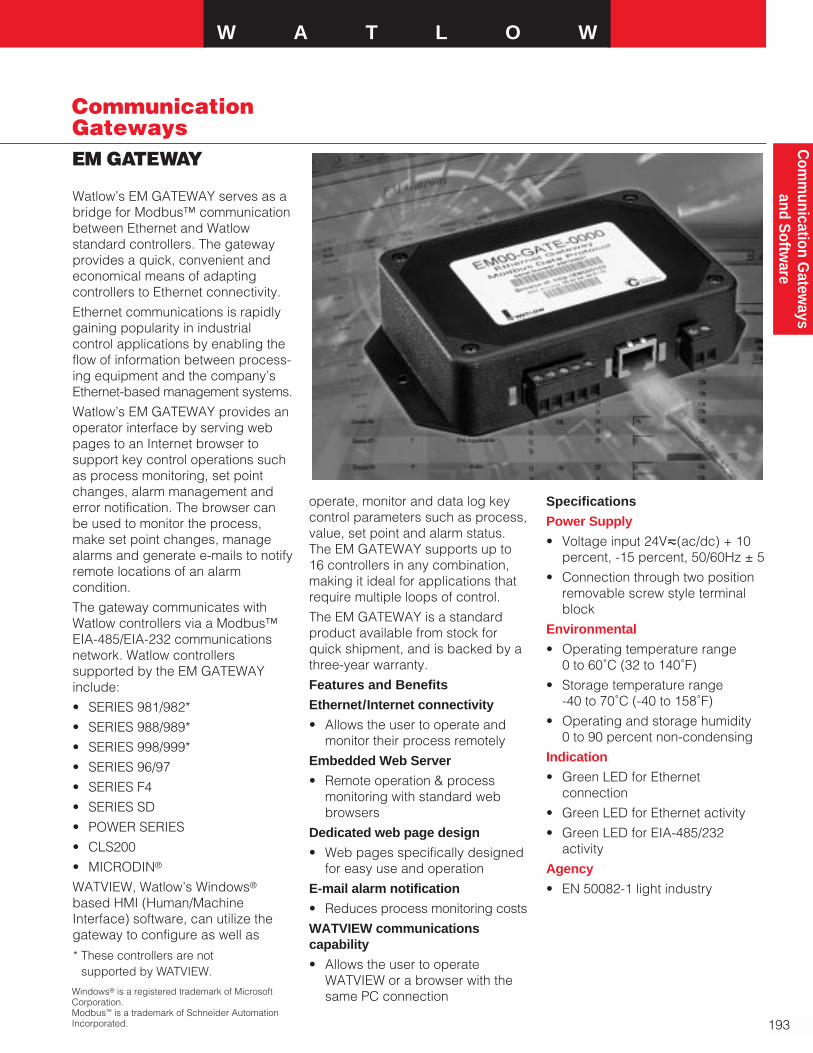
W A T L O W
193
Com
munication G
ateways
and Softw
are
EM GATEWAY
CommunicationGateways
Watlow’s EM GATEWAY serves as abridge for Modbus™ communicationbetween Ethernet and Watlowstandard controllers. The gatewayprovides a quick, convenient andeconomical means of adaptingcontrollers to Ethernet connectivity.
Ethernet communications is rapidlygaining popularity in industrialcontrol applications by enabling theflow of information between process-ing equipment and the company’sEthernet-based management systems.
Watlow’s EM GATEWAY provides anoperator interface by serving webpages to an Internet browser tosupport key control operations suchas process monitoring, set pointchanges, alarm management anderror notification. The browser canbe used to monitor the process,make set point changes, managealarms and generate e-mails to notifyremote locations of an alarmcondition.
The gateway communicates withWatlow controllers via a Modbus™EIA-485/EIA-232 communicationsnetwork. Watlow controllerssupported by the EM GATEWAYinclude:
• SERIES 981/982*
• SERIES 988/989*
• SERIES 998/999*
• SERIES 96/97
• SERIES F4
• SERIES SD
• POWER SERIES
• CLS200
• MICRODIN®
WATVIEW, Watlow’s Windows®
based HMI (Human/MachineInterface) software, can utilize thegateway to configure as well as
operate, monitor and data log keycontrol parameters such as process,value, set point and alarm status.The EM GATEWAY supports up to16 controllers in any combination,making it ideal for applications thatrequire multiple loops of control.
The EM GATEWAY is a standardproduct available from stock forquick shipment, and is backed by athree-year warranty.
Features and Benefits
Ethernet/Internet connectivity
• Allows the user to operate andmonitor their process remotely
Embedded Web Server
• Remote operation & processmonitoring with standard webbrowsers
Dedicated web page design
• Web pages specifically designedfor easy use and operation
E-mail alarm notification
• Reduces process monitoring costs
WATVIEW communicationscapability
• Allows the user to operateWATVIEW or a browser with thesame PC connection
Specifications
Power Supply
• Voltage input 24Vı(ac/dc) + 10percent, -15 percent, 50/60Hz ± 5
• Connection through two positionremovable screw style terminalblock
Environmental
• Operating temperature range 0 to 60˚C (32 to 140˚F)
• Storage temperature range -40 to 70˚C (-40 to 158˚F)
• Operating and storage humidity 0 to 90 percent non-condensing
Indication
• Green LED for Ethernetconnection
• Green LED for Ethernet activity
• Green LED for EIA-485/232activity
Agency
• EN 50082-1 light industry
Windows® is a registered trademark of MicrosoftCorporation.Modbus™ is a trademark of Schneider AutomationIncorporated.
* These controllers are notsupported by WATVIEW.

194
CommunicationGatewaysEM GATEWAY
Communications
• Modbus™ RTU communications
• EIA-485/EIA-232 supported
• Connection through fiveposition removable screw style terminal block
• Ethernet communications
• Ethernet RJ 45 connector
• 10 base T
• HTTP interface
• Modbus™ TCP
• DHCP, Auto IP or fixed IPaddress
• E-mail alarm notification
Dimensions
• 85.09 mm (3.35 in.) width 139.7 mm (5.50 in.) length 34.54 mm (1.36 in.) depth
Specifications Cont.
Ordering Information
Order part number EM00-GATE-0000
Top View
85.09 mm (3.35 in.)
127 mm (5.0 in.)
139.7 mm (5.50 in.)
53.85 mm (2.12 in.)
ø .19
Front View
EM GATEWAY Network Wiring Diagram
F.O.B.: Winona, Minnesota
34.54 mm (1.36 in.)
3.18 mm (0.125 in.)
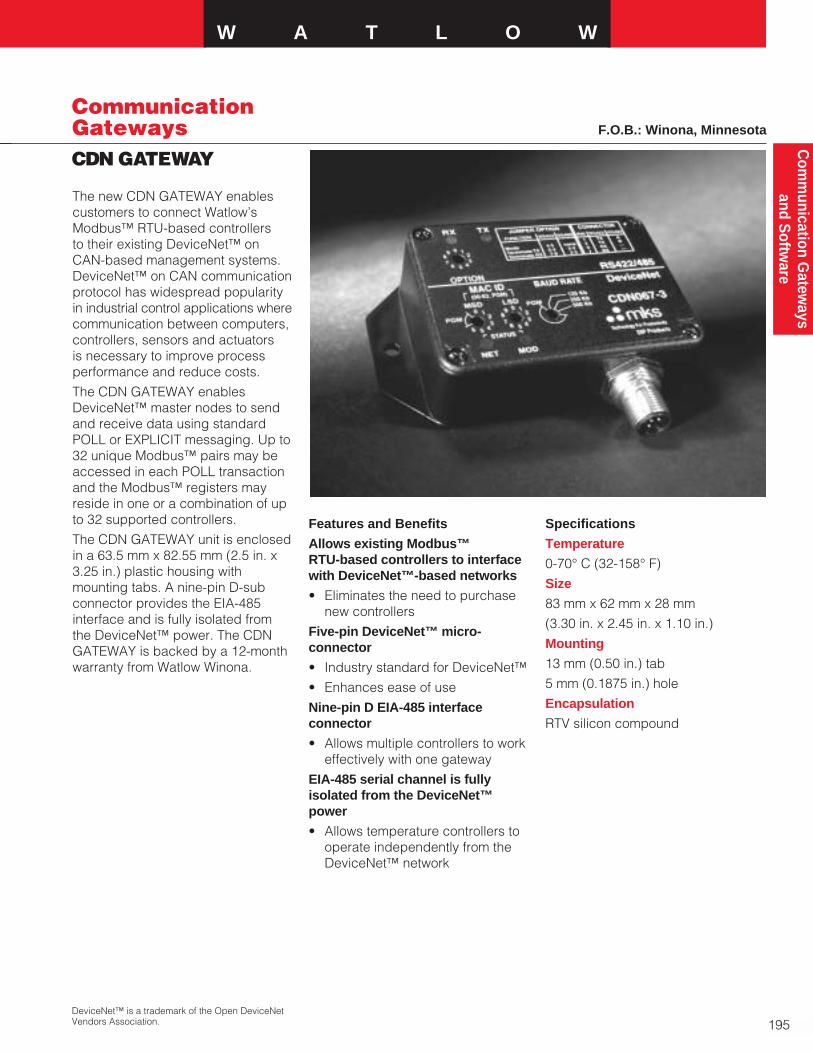
W A T L O W
195
Com
munication G
ateways
and Softw
are
CDN GATEWAY
CommunicationGateways
The new CDN GATEWAY enablescustomers to connect Watlow’sModbus™ RTU-based controllers to their existing DeviceNet™ onCAN-based management systems.DeviceNet™ on CAN communicationprotocol has widespread popularityin industrial control applications wherecommunication between computers,controllers, sensors and actuators is necessary to improve processperformance and reduce costs.
The CDN GATEWAY enablesDeviceNet™ master nodes to sendand receive data using standardPOLL or EXPLICIT messaging. Up to32 unique Modbus™ pairs may beaccessed in each POLL transactionand the Modbus™ registers mayreside in one or a combination of upto 32 supported controllers.
The CDN GATEWAY unit is enclosedin a 63.5 mm x 82.55 mm (2.5 in. x3.25 in.) plastic housing withmounting tabs. A nine-pin D-subconnector provides the EIA-485interface and is fully isolated fromthe DeviceNet™ power. The CDNGATEWAY is backed by a 12-monthwarranty from Watlow Winona.
Features and Benefits
Allows existing Modbus™RTU-based controllers to interfacewith DeviceNet™-based networks
• Eliminates the need to purchasenew controllers
Five-pin DeviceNet™ micro-connector
• Industry standard for DeviceNet™
• Enhances ease of use
Nine-pin D EIA-485 interfaceconnector
• Allows multiple controllers to workeffectively with one gateway
EIA-485 serial channel is fullyisolated from the DeviceNet™power
• Allows temperature controllers tooperate independently from theDeviceNet™ network
Specifications
Temperature
0-70° C (32-158° F)
Size
83 mm x 62 mm x 28 mm
(3.30 in. x 2.45 in. x 1.10 in.)
Mounting
13 mm (0.50 in.) tab
5 mm (0.1875 in.) hole
Encapsulation
RTV silicon compound
DeviceNet™ is a trademark of the Open DeviceNetVendors Association.
F.O.B.: Winona, Minnesota

196

Searching for a quick, efficient wayto set up your controllers? Needrapid data-logging and graphingcapabilities? We have the answer:WATVIEW.
WATVIEW is Watlow Anafaze’s HMI(Human/Machine Interface) softwaredesigned to set up and monitor up to 32 Watlow controllers. With easycontroller setup, a recipe and alarmmanager, data-logging and trendplot graphing capabilities, animatedcustom overview screens and asuperior online help system, you canbe assured that WATVIEW is theideal software for your application.
WATVIEW Editions:
WATVIEW is available in threeeditions making your softwaredecision quick and effortless.
• WATVIEW-R: The Run-Time EditionProvides trend plot graphing,setup screens, data-logging,recipe manager with calendar-start, spreadsheet data editor,system activity log and alarmmanager. The Run-Time Editionwill “play back” custom screenscreated with the DeveloperEdition.
• WATVIEW-D: The Developer EditionIncludes all functions of the Run-Time Edition plus a customscreen designer and user-definedvariables.
• WATVIEW-C: The Configurator EditionIncludes only spreadsheet dataeditor, recipe manager withoutcalendar-start and system activity log.
Features and Benefits
Easy controller setup
• WATVIEW automatically detectswhich controllers are connectedto the computer, then WATVIEWloads the appropriate setupscreens for those controllers. Use built-in setup screens toadjust the controller parameters,or the simple “spreadsheet view”for a quick, intuitive interface. Thespreadsheet categorizes allcontroller parameters accordingto their parameter groupings.
Recipe manager
• All editions of WATVIEW includethe ability to create recipes(arrays of controller settings).Recipes can be created, edited,stored and downloaded to thecontrollers. Use recipes to storecommonly used controllersettings, to speed up repetitivecontroller setups and to create a“snapshot” of your setups.
The Run-Time and DeveloperEditions also include a calendar-start function, allowing users toautomatically download recipeson a one-time or repeatingschedule.
Alarm manager
• WATVIEW Run-Time andDeveloper Editions receive alarmsfrom controllers, maintain a log ofalarms and allow users to clearand acknowledge alarms.
Data-logging and trend plot graphs
• WATVIEW Run-Time andDeveloper Editions includecontinuous data-logging of theparameters you choose. You canexport the collected data to anExcel®-compatible spreadsheetfile, or view up to 20 data items ona WATVIEW trend plot graph. Anunlimited number of graphs maybe named and stored for simplefuture retrieval.
W A T L O W
197
Com
munication G
ateways
and Softw
are
SoftwareWATVIEW HMISoftware
Excel® is a registered trademark of MicrosoftCorporation.
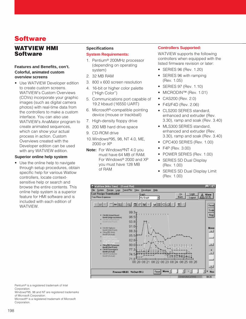
198
SoftwareWATVIEW HMISoftware
Colorful, animated customoverview screens
• Use WATVIEW Developer editionto create custom screens.WATVIEW’s Custom Overviews(COVs) incorporate your graphicimages (such as digital cameraphotos) with real-time data fromthe controllers to make a custominterface. You can also useWATVIEW’s AnaMator program tocreate animated sequences,which can show your actualprocess in action. CustomOverviews created with theDeveloper edition can be usedwith any WATVIEW edition.
Superior online help system
• Use the online help to navigatethrough setup procedures, obtainspecific help for various Watlowcontrollers, locate context-sensitive help or search andbrowse the entire contents. Thisonline help system is a superiorfeature for HMI software and isincluded with each edition ofWATVIEW.
Specifications
System Requirements:
1. Pentium® 200MHz processor(depending on operatingsystem)
2. 32 MB RAM
3. 800 x 600 screen resolution
4. 16-bit or higher color palette(“High Color”)
5. Communications port capable of19.2 kbaud (16550 UART)
6. Microsoft®-compatible pointingdevice (mouse or trackball)
7. High-density floppy drive
8. 200 MB hard drive space
9. CD-ROM drive
10.Windows®95, 98, NT 4.0, ME,2000 or XP
Note: For Windows®NT 4.0 youmust have 64 MB of RAM. For Windows® 2000 and XPyou must have 128 MB of RAM
Controllers Supported:
WATVIEW supports the followingcontrollers when equipped with thelisted firmware revision or later:
• SERIES 96 (Rev. 1.20)
• SERIES 96 with ramping (Rev. 1.05)
• SERIES 97 (Rev. 1.10)
• MICRODIN™ (Rev. 1.01)
• CAS200 (Rev. 2.0)
• F4S/F4D (Rev. 2.06)
• CLS200 SERIES standard,enhanced and extruder (Rev.3.30), ramp and soak (Rev. 3.40)
• MLS300 SERIES standard,enhanced and extruder (Rev.3.30), ramp and soak (Rev. 3.40)
• CPC400 SERIES (Rev. 1.00)
• F4P (Rev. 3.00)
• POWER SERIES (Rev. 1.00)
• SERIES SD Dual Display (Rev. 1.00)
• SERIES SD Dual Display Limit(Rev. 1.00)
Pentium® is a registered trademark of IntelCorporation.Windows®95, 98 and NT are registered trademarksof Microsoft Corporation.Microsoft® is a registered trademark of MicrosoftCorporation.
Features and Benefits, con’t.
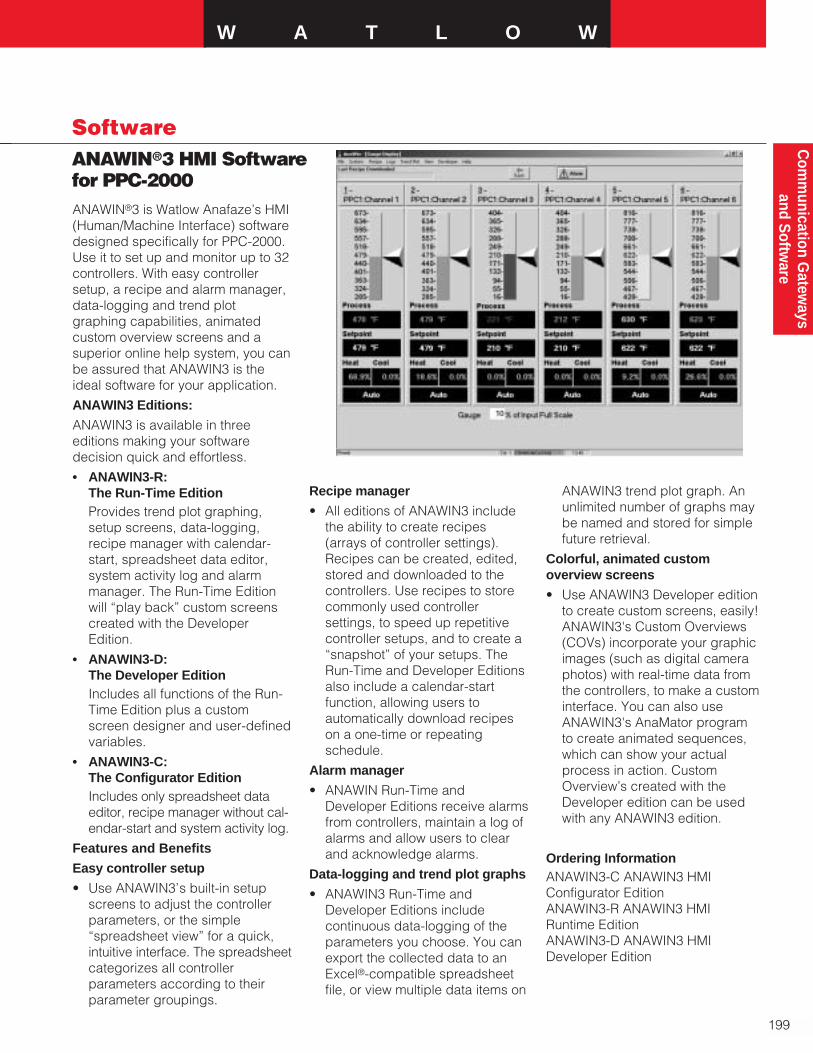
W A T L O W
199
Com
munication G
ateways
and Softw
are
ANAWIN®3 HMI Softwarefor PPC-2000
Software
ANAWIN®3 is Watlow Anafaze’s HMI(Human/Machine Interface) softwaredesigned specifically for PPC-2000.Use it to set up and monitor up to 32controllers. With easy controllersetup, a recipe and alarm manager,data-logging and trend plotgraphing capabilities, animatedcustom overview screens and asuperior online help system, you canbe assured that ANAWIN3 is theideal software for your application.
ANAWIN3 Editions:
ANAWIN3 is available in threeeditions making your softwaredecision quick and effortless.
• ANAWIN3-R: The Run-Time EditionProvides trend plot graphing,setup screens, data-logging,recipe manager with calendar-start, spreadsheet data editor,system activity log and alarmmanager. The Run-Time Editionwill “play back” custom screenscreated with the DeveloperEdition.
• ANAWIN3-D: The Developer EditionIncludes all functions of the Run-Time Edition plus a customscreen designer and user-definedvariables.
• ANAWIN3-C: The Configurator EditionIncludes only spreadsheet dataeditor, recipe manager without cal-endar-start and system activity log.
Features and Benefits
Easy controller setup
• Use ANAWIN3’s built-in setupscreens to adjust the controllerparameters, or the simple“spreadsheet view” for a quick,intuitive interface. The spreadsheetcategorizes all controllerparameters according to theirparameter groupings.
Recipe manager
• All editions of ANAWIN3 includethe ability to create recipes(arrays of controller settings).Recipes can be created, edited,stored and downloaded to thecontrollers. Use recipes to storecommonly used controllersettings, to speed up repetitivecontroller setups, and to create a“snapshot” of your setups. TheRun-Time and Developer Editionsalso include a calendar-startfunction, allowing users toautomatically download recipeson a one-time or repeatingschedule.
Alarm manager
• ANAWIN Run-Time andDeveloper Editions receive alarmsfrom controllers, maintain a log ofalarms and allow users to clearand acknowledge alarms.
Data-logging and trend plot graphs
• ANAWIN3 Run-Time andDeveloper Editions includecontinuous data-logging of theparameters you choose. You canexport the collected data to anExcel®-compatible spreadsheetfile, or view multiple data items on
ANAWIN3 trend plot graph. Anunlimited number of graphs maybe named and stored for simplefuture retrieval.
Colorful, animated customoverview screens
• Use ANAWIN3 Developer editionto create custom screens, easily!ANAWIN3's Custom Overviews(COVs) incorporate your graphicimages (such as digital cameraphotos) with real-time data fromthe controllers, to make a custominterface. You can also useANAWIN3's AnaMator program to create animated sequences,which can show your actualprocess in action. CustomOverview’s created with theDeveloper edition can be usedwith any ANAWIN3 edition.
Ordering InformationANAWIN3-C ANAWIN3 HMIConfigurator EditionANAWIN3-R ANAWIN3 HMI Runtime EditionANAWIN3-D ANAWIN3 HMIDeveloper Edition

200
SoftwareWATCONNECT™CommunicationsLibrary
WATCONNECT™ is Watlow’s newWindows®-based software library forModbus™-RTU communications. Thissoftware tool kit makes it easy forprogrammers working in Visual Basic,C, C++ and Visual C++ to developWindows® applications that commun-icate with Watlow controllers usingthe Modbus™ RTU protocol. Thesimplicity of the interface insures ashort learning curve and shorteneddevelopment times for HumanMachine Interface or other appli-cations that communicate withcontrollers.
The main benefit of the tool kit is thatthe programmer does not need tolearn the details of the Modbus™protocol or the operation of aWindows® serial port to successfullydevelop programs that read and setparameter values in controllers. Thelibrary provides four, easy-to-usefunctions: open port, close port, readdata and write data. To use thesefunctions, the programmer justneeds to know the communicationsport settings and address of thedesired data.
For more information, please contactyour local Watlow representative.
Features and Benefits
Allows communication with one to247 controllers
• Scalable
Safe for multithreaded applications
• Several parts of a program canuse the same communicationsport
Single source solution
• Eliminates multiple vendors
• Assures compatibility
• Saves time and money
License agreement allows userwritten applications to bedistributed royalty free
• Adds no recurring cost toapplications
Sample code provided for VisualC++ and Visual Basicenvironments
• Easy to follow examples shortenthe learning curve
Reads and writes all standardModbus™ data table locations:coils, inputs and registers
• Allows access to all controllerparameters
Can handle custom-named portssuch as serial port expanders
• Assures flexibility
Windows® is a registered trademark of MicrosoftCorporation.
Modbus™ is trademark of AEG SchneiderCorporation.

W A T L O W
201
Com
munication G
ateways
and Softw
are
LOGICPRO™:Logic ProgrammingSoftware for PPC-2000and CPC400
Software
LOGICPRO™
LOGICPRO™ is a Windows®-basedgraphical logic programmingsoftware package. LOGICPRO is theperfect counterpart to the powerfulmulti-loop PID control features in thePPC-2000 and CPC400. Developprograms in a choice of three logicprogramming languages: ladderdiagram, sequential function chart orfunction block diagram.
Features and Benefits
Develops custom logic programswith easy-to-use, drag-and-droptools, then simulates and debugson the development PC beforedownloading to the PPC-2000
• Reduces time and cost duringsystem start-up, trouble-shootingand fine tuning
Real-time monitoring
• Reduces time to verify systemlogic operation
Integrates programmable logic andPID control in a single controller
• Eliminates cumbersome andinflexible communicationsschemes between separateprocess and logic controllers,saving development time andcosts
Full set of logic functions andprogramming tools
• Adds value by easily customizingyour process
LOGICPRO Editions
LOGICPRO-S supports up to 150 I/Odriver points. I/O driver points arephysical I/O and any data tableaccessed parameters.
LOGICPRO-P supports an unlimitednumber of I/O points. Both utilize keys,which are attached to the devel-opment computer's parallel port.
System requirements:
• IBM compatible PC
• EIA-232 serial port
• Pentium® processor, 166 MHzminimum
• Windows® 95/98 or Windows® NT
• 32 MB RAM
• 40 MB minimum hard disk space
• Parallel port
Ordering Information
LOGICPRO-S LOGICPRO StandardEdition
LOGICPRO-P LOGICPROProfessional Edition

202
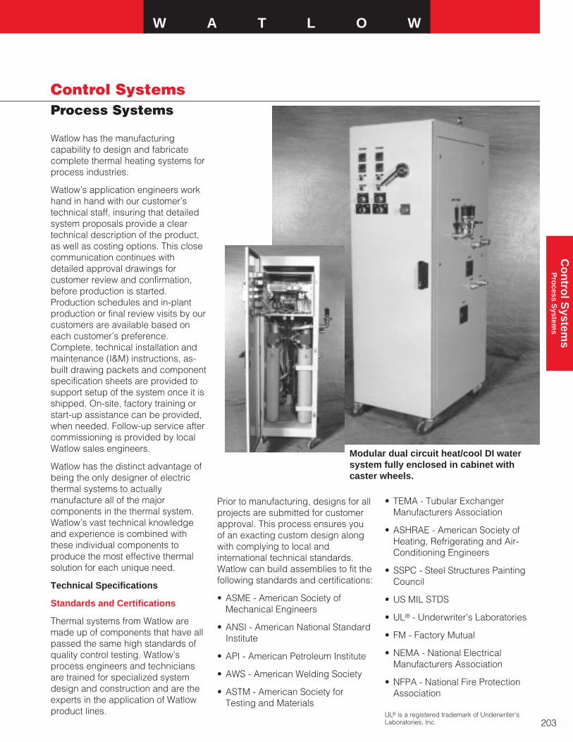
W A T L O W
203
Co
ntro
l System
s P
rocess S
ystems
Control SystemsProcess Systems
Watlow has the manufacturingcapability to design and fabricatecomplete thermal heating systems forprocess industries.
Watlow’s application engineers workhand in hand with our customer’stechnical staff, insuring that detailedsystem proposals provide a cleartechnical description of the product,as well as costing options. This closecommunication continues withdetailed approval drawings forcustomer review and confirmation,before production is started.Production schedules and in-plantproduction or final review visits by ourcustomers are available based oneach customer’s preference.Complete, technical installation andmaintenance (I&M) instructions, as-built drawing packets and componentspecification sheets are provided tosupport setup of the system once it isshipped. On-site, factory training orstart-up assistance can be provided,when needed. Follow-up service aftercommissioning is provided by localWatlow sales engineers.
Watlow has the distinct advantage ofbeing the only designer of electricthermal systems to actuallymanufacture all of the majorcomponents in the thermal system.Watlow’s vast technical knowledgeand experience is combined withthese individual components toproduce the most effective thermalsolution for each unique need.
Technical Specifications
Standards and Certifications
Thermal systems from Watlow aremade up of components that have allpassed the same high standards ofquality control testing. Watlow’sprocess engineers and techniciansare trained for specialized systemdesign and construction and are theexperts in the application of Watlowproduct lines.
Prior to manufacturing, designs for allprojects are submitted for customerapproval. This process ensures youof an exacting custom design alongwith complying to local andinternational technical standards.Watlow can build assemblies to fit thefollowing standards and certifications:
• ASME - American Society ofMechanical Engineers
• ANSI - American National StandardInstitute
• API - American Petroleum Institute
• AWS - American Welding Society
• ASTM - American Society forTesting and Materials
• TEMA - Tubular ExchangerManufacturers Association
• ASHRAE - American Society ofHeating, Refrigerating and Air-Conditioning Engineers
• SSPC - Steel Structures PaintingCouncil
• US MIL STDS
• UL® - Underwriter’s Laboratories
• FM - Factory Mutual
• NEMA - National ElectricalManufacturers Association
• NFPA - National Fire ProtectionAssociation
Modular dual circuit heat/cool DI watersystem fully enclosed in cabinet withcaster wheels.
UL® is a registered trademark of Underwriter’sLaboratories, Inc.

204
Control SystemsProcess Systems
• NEC - National Electric Code
• CSA - Canadian StandardsAssociation
• CE - European Union Mark ofConformance
• CENELEC - European Committeefor Electrotechnical Standardization
• PED - European Union PressureEquipment Directive
• BASEEFA - British ApprovalService for Electrical Equipment inFlammable Atmospheres
• IEC - International ElectrotechnicalCommission
• JIC - Joint Industrial Council
• SEMI-S2 - SemiconductorEquipment and Materials Institute
Testing and Services
Watlow can provide special testingand services for a variety of needs.These include:
• Radiography
• Charpy impact testing
• Die penetrant testing
• Hydrostatic pressure testing
• Ultrasonic thickness testing
• Magnetic particle testing
• MTRs (Material Test Reports)
• ASME calculations
• Earthquake, stress or vibrationcalculations
• PE stamp documents (ProfessionalEngineer)
• Helium leak testing
• Tensile testing
• PMI (Positive Material Identification)testing
• Post-weld heat treating
• Chemical passivation
• Electropolishing
• Microscopic analysis
• Brinell hardness testing
• Special metal coatings fromthermal spray to galvanizing
Summary of Product Capabilitiesand Services
Watlow builds any system to suit yourneeds. We design and fabricatespecialty systems to simulate uniqueindustry needs. Some of thecapabilities available to build aWatlow process system include:
• Complete fabrication of low alloycarbon steel through alloy 800, alloy600, alloy 20 and all exotic metals
• Fabrication of special parts of withCNC machining, lathes, mills,plasma cutting and laser cutting
• ASME Section IX welder and weldprocedure qualifications, ASME“U,” “S” and “R” stamps
• Electrical control panel design andassembly. UL® listed and CEcertified panels available
• Full interconnection of varioussystem components prior toshipment to minimize fieldinstallation difficulties
• Design and fabrication of largersystems - heater sizes from singleelement, 20 watt assemblies to 600plus elements, 1016 mm (40 in.)flanges, to multi-vessel stackedsystems to 2.5 megawatt
• Standard vessel fabrication up to1524 mm (60 in.) diameter and wallthickness from schedule five tospecialty plate rolled vessels over25.4 mm (1 in.) thick with lengthsup to 20 feet, larger sizes can alsobe provided
• Ability to integrate valves, pumps,flow switches, strainers, expansionjoints, expansion tanks, level glass,level switches, blowers,compressors, differential pressureswitches and all fluid flowcomponents as required
• Specialize in high pressure andhigh temperature design includingpressures to 4500 psi and gasheating from cryogenic -226°C to982°C (-375°F to 1800°F)
• Heater systems designed with bestheater for application. Low endtemperatures using silicone rubberheaters to ultra-high temperatureusing ceramic fiber heaters
• Skid-mounting designing andfabrication
• Piping design and fabrication
• Fabrication of heating and controlsystems for all hazardous and non-hazardous locations. CSA andCENELEC certified enclosures to1270 mm (50 in.) flange
• Special cleaning proceduresincluding passivation andelectropolishing
• Special finishing, blasting andpainting of complete thermalsystems
• Special packaging and crating fordomestic and export systems
• Able to ship F.O.B. factory, F.O.B.U.S. port, ex-factory, C&Fdestination, CIF destination
• Can coordinate all FreightForwarder shipping issues to insuresmooth and timely export
• Complete I&M packages, drawings,nameplates in English or otherinternational languages as required
• On-site technical reviews, training,commissioning, service by factoryengineers and local representatives

W A T L O W
205
Co
ntro
l System
s P
rocess S
ystems
Control SystemsProcess Systems
Multi-Zone Control Panel
• Four Watlow Anafaze 32MLS controllers
• 128 total control loops
• Four loops per zone
• Two process and two alarm outputs
• Emergency stop pushbutton
• Interior lighting
• NEMA 12 fan cooled cabinet
Each zone contains
• On-off selector switch with pilot light
• Watlow DIN-A-MITE® for power switching
• Capacitors and resistors for Torodial heater coil
22-Zone Control System
• 75 kVA, 480V x 240V step-down transformer
• Four C-Style DIN-A-MITE SCR power switching devices
• Three Watlow Anafaze MLS332 multi-loop controllers
• Four Watlow SERIES 988 temperature controllers withremote set point
• NEMA 12 skid-mounted cabinet
• Main disconnect switch
• 22 safety contactors
• 22 sets of load fusing
• Watt transducer
Water Heating System
• Two 50kW heaters piped in parallel
• 60 gpm pump
• Solenoid valve
• Isolation valve
• Flow switches
• High limit thermocouples
Completely interconnected to control system consisting of:
• Watlow process temperature and limit temperaturecontrollers
• Main disconnect
• Mechanical contactors for power switching
F.O.B.: Wright City, Missouri
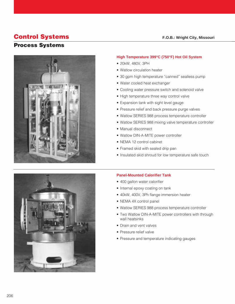
206
Control SystemsProcess Systems
High Temperature 399°C (750°F) Hot Oil System
• 20kW, 480V, 3PH
• Watlow circulation heater
• 30 gpm high temperature “canned” sealless pump
• Water cooled heat exchanger
• Cooling water pressure switch and solenoid valve
• High temperature three way control valve
• Expansion tank with sight level gauge
• Pressure relief and back pressure purge valves
• Watlow SERIES 988 process temperature controller
• Watlow SERIES 988 mixing valve temperature controller
• Manual disconnect
• Watlow DIN-A-MITE power controller
• NEMA 12 control cabinet
• Framed skid with sealed drip pan
• Insulated skid shroud for low temperature safe touch
Panel-Mounted Calorifier Tank
• 400 gallon water calorifier
• Internal epoxy coating on tank
• 40kW, 400V, 3Ph flange immersion heater
• NEMA 4X control panel
• Watlow SERIES 988 process temperature controller
• Two Watlow DIN-A-MITE power controllers with throughwall heatsinks
• Drain and vent valves
• Pressure relief valve
• Pressure and temperature indicating gauges
F.O.B.: Wright City, Missouri
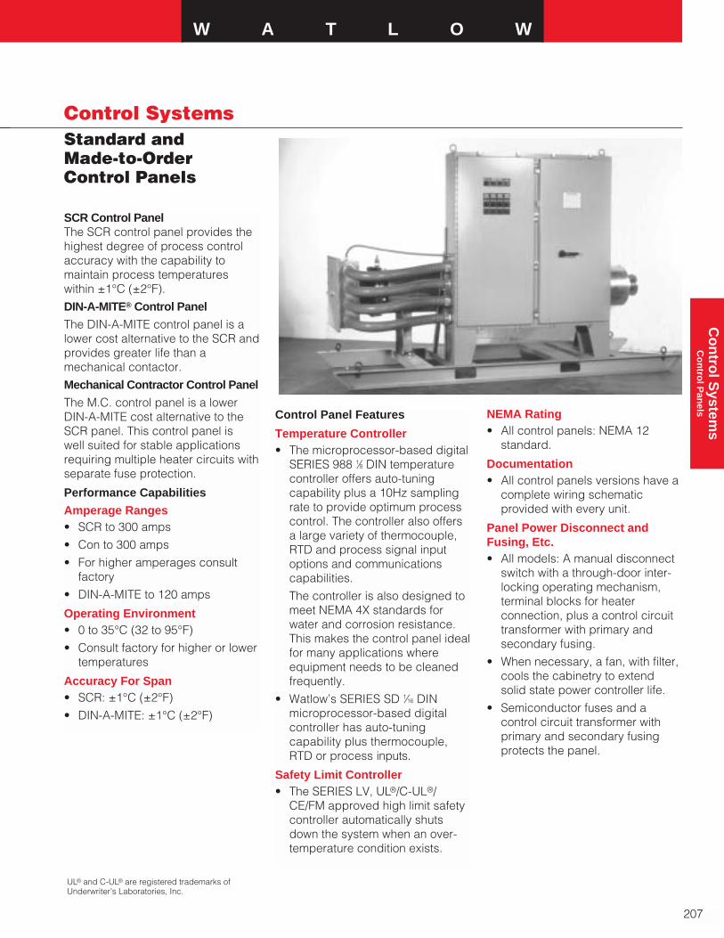
Standard and Made-to-OrderControl Panels
W A T L O W
207
Co
ntro
l System
s C
on
trol P
anels
Control Systems
SCR Control PanelThe SCR control panel provides thehighest degree of process controlaccuracy with the capability tomaintain process temperatureswithin ±1°C (±2°F).
DIN-A-MITE® Control Panel
The DIN-A-MITE control panel is alower cost alternative to the SCR andprovides greater life than amechanical contactor.
Mechanical Contractor Control Panel
The M.C. control panel is a lowerDIN-A-MITE cost alternative to theSCR panel. This control panel iswell suited for stable applicationsrequiring multiple heater circuits withseparate fuse protection.
Performance Capabilities
Amperage Ranges• SCR to 300 amps
• Con to 300 amps
• For higher amperages consultfactory
• DIN-A-MITE to 120 amps
Operating Environment• 0 to 35°C (32 to 95°F)
• Consult factory for higher or lowertemperatures
Accuracy For Span• SCR: ±1°C (±2°F)
• DIN-A-MITE: ±1°C (±2°F)
Control Panel Features
Temperature Controller• The microprocessor-based digital
SERIES 988 1⁄8 DIN temperaturecontroller offers auto-tuningcapability plus a 10Hz samplingrate to provide optimum processcontrol. The controller also offersa large variety of thermocouple,RTD and process signal inputoptions and communicationscapabilities.
The controller is also designed tomeet NEMA 4X standards forwater and corrosion resistance.This makes the control panel idealfor many applications whereequipment needs to be cleanedfrequently.
• Watlow’s SERIES SD 1⁄16 DINmicroprocessor-based digitalcontroller has auto-tuningcapability plus thermocouple,RTD or process inputs.
Safety Limit Controller• The SERIES LV, UL®/C-UL®/
CE/FM approved high limit safetycontroller automatically shutsdown the system when an over-temperature condition exists.
NEMA Rating• All control panels: NEMA 12
standard.
Documentation• All control panels versions have a
complete wiring schematicprovided with every unit.
Panel Power Disconnect andFusing, Etc.• All models: A manual disconnect
switch with a through-door inter-locking operating mechanism,terminal blocks for heaterconnection, plus a control circuittransformer with primary andsecondary fusing.
• When necessary, a fan, with filter,cools the cabinetry to extendsolid state power controller life.
• Semiconductor fuses and acontrol circuit transformer withprimary and secondary fusingprotects the panel.
UL® and C-UL® are registered trademarks ofUnderwriter’s Laboratories, Inc.
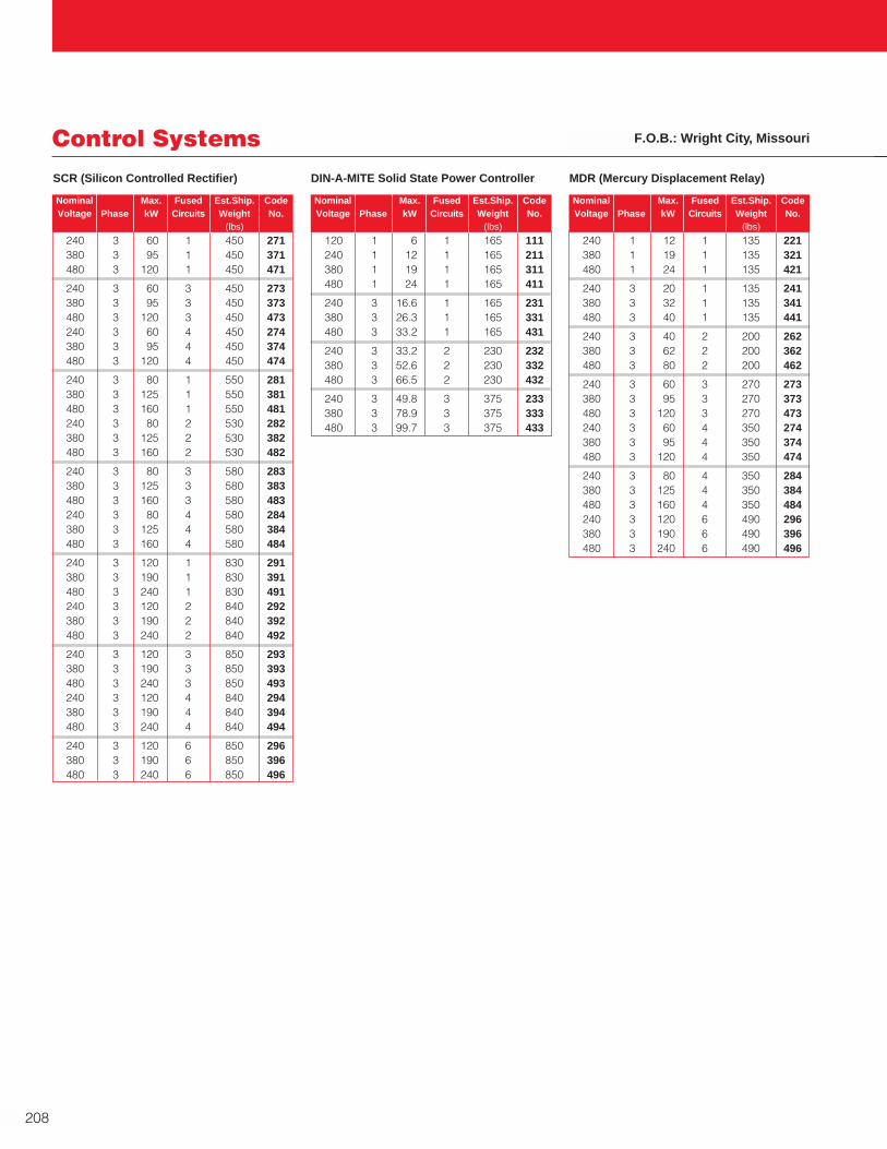
120 1 6 1 165 111240 1 12 1 165 211380 1 19 1 165 311480 1 24 1 165 411
240 3 16.6 1 165 231380 3 26.3 1 165 331480 3 33.2 1 165 431
240 3 33.2 2 230 232380 3 52.6 2 230 332480 3 66.5 2 230 432
240 3 49.8 3 375 233380 3 78.9 3 375 333480 3 99.7 3 375 433
240 3 60 1 450 271380 3 95 1 450 371480 3 120 1 450 471
240 3 60 3 450 273380 3 95 3 450 373480 3 120 3 450 473240 3 60 4 450 274380 3 95 4 450 374480 3 120 4 450 474
240 3 80 1 550 281380 3 125 1 550 381480 3 160 1 550 481240 3 80 2 530 282380 3 125 2 530 382480 3 160 2 530 482
240 3 80 3 580 283380 3 125 3 580 383480 3 160 3 580 483240 3 80 4 580 284380 3 125 4 580 384480 3 160 4 580 484
240 3 120 1 830 291380 3 190 1 830 391480 3 240 1 830 491240 3 120 2 840 292380 3 190 2 840 392480 3 240 2 840 492
240 3 120 3 850 293380 3 190 3 850 393480 3 240 3 850 493240 3 120 4 840 294380 3 190 4 840 394480 3 240 4 840 494
240 3 120 6 850 296380 3 190 6 850 396480 3 240 6 850 496
208
Control Systems F.O.B.: Wright City, Missouri
SCR (Silicon Controlled Rectifier) DIN-A-MITE Solid State Power Controller
Nominal Max. Fused Est.Ship. Code Voltage Phase kW Circuits Weight No.
(lbs)
Nominal Max. Fused Est.Ship. Code Voltage Phase kW Circuits Weight No.
(lbs)
Nominal Max. Fused Est.Ship. Code Voltage Phase kW Circuits Weight No.
(lbs)
MDR (Mercury Displacement Relay)
240 1 12 1 135 221380 1 19 1 135 321480 1 24 1 135 421
240 3 20 1 135 241380 3 32 1 135 341480 3 40 1 135 441
240 3 40 2 200 262380 3 62 2 200 362480 3 80 2 200 462
240 3 60 3 270 273380 3 95 3 270 373480 3 120 3 270 473240 3 60 4 350 274380 3 95 4 350 374480 3 120 4 350 474
240 3 80 4 350 284380 3 125 4 350 384480 3 160 4 350 484240 3 120 6 490 296380 3 190 6 490 396480 3 240 6 490 496
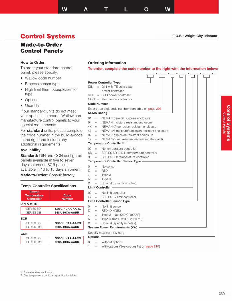
Made-to-OrderControl Panels
W A T L O W
209
Co
ntro
l System
s C
on
trol P
anels
Control Systems
Ordering Information
To order, complete the code number to the right with the information below:_ _ _ - _ _ _ - _ _ - _ _ _ - _ _ _ - _ _ _ - _
Power Controller TypeDIN = DIN-A-MITE solid state
power controllerSCR = SCR power controllerCON = Mechanical contractor
Code Number
Enter three digit code number from table on page 208NEMA Rating
01 = NEMA 1 general purpose enclosure04 = NEMA 4 moisture resistant enclosure4X = NEMA 4Xa corrosion resistant enclosure47 = NEMA 4/7 moisture/explosion resistant enclosure07 = NEMA 7 explosion resistant enclosure12 = NEMA 12 dust resistant enclosure (standard)Temperature Controllerb
00 = No temperature controllerSD = SERIES SD 1⁄16 DIN temperature controller98 = SERIES 988 temperature controllerTemperature Controller Sensor Type
0 = No sensorD = RTDJ = Type JK = Type KX = Special (Specify in notes)Limit Controller
00 = No limit controllerLV = SERIES LV limit controller Limit Controller Sensor Type
0 = No limit sensorD = RTD (DIN/JIS)J = Type J (max. 540°C/1000°F)K = Type K (max. 1205°C/2200°F)X = Special (specify in notes)System Power Requirements (kW)
Specify maximum kW hereOptions
0 = Without options1 = With options (See options list on page 210)
a Stainless steel enclosure.b See temperature controller specification table.
How to OrderTo order your standard controlpanel, please specify:
• Watlow code number
• Process sensor type
• High limit thermocouple/sensortype
• Options
• Quantity
If our standard units do not meetyour application needs, Watlow canmanufacture control panels to yourspecial requirements.
For standard units, please completethe code number in the build-a-codeto the right and include anyadditional requirements.
Availability
Standard: DIN and CON configuredpanels available in five to sevendays shipment. SCR panelsavailable in 10 to 15 days shipment.
Made-to-Order: Consult factory.
SERIES SD SD6C-HCAA-AARGSERIES 988 988A-10CA-AARR
Power/Temperature Code
Controller Number
Temp. Controller Specifications
SERIES SD SD6C-HCAA-AARGSERIES 988 988A-10CA-AARR
DIN-A-MITE
SCR
SERIES SD SD6C-HKAA-AARGSERIES 988 988A-10BA-AARR
CON
F.O.B.: Wright City, Missouri

Made-to-OrderControl Panels
210
Control Systems
Accessories• Air conditioning/mechanical
cooling
• Air-flow switch
• Alarm (with alarm silence pushbutton)
• Amperage meter
• Back-up mechanical contactors(per load circuit)
• Circuit breaker
• Conformal coating
• Control panel (UL® listed per UL® 508)
• Control relay
• Enclosure heater
• Expedited shipping date
• Fungicide protection
16 mm(0.625 in.)
5 mm(0.1875 in.)
Width
76 mm(3 in.)
11 mm Dia., Typical(0.4375 in.) 16 mm
(0.625 in.)
31 mm(1.1875 in.)
Height
NEMA 12 PanelDimensions
150 1260 x 915 x 305(48 x 36 x 12)
200 1524 x 915 x 305(60 x 36 x 12)
300 1524 x 1220 x 406(60 x 48 x 16)
50 610 x 510 x 205(24 x 20 x 8)
100 760 x 610 x 205(30 x 24 x 8)
150 & 200 1030 x 915 x 205(42 x 36 x 8)
300 1524 x 915 x 305(60 x 36 x 12)
20, 40, 50 610 x 508 x 254(24 x 20 x 10)
80 914 x 610 x 254(36 x 24 x 10)
120 1065 x 915 x 255(42 x 36 x 10)
Amps Size mm (in.)
SCR
DIN-A-MITE
CON
• Ground fault detection with relay
• Installation operation andmaintenance manual
• Interlocks
• Mechanical cooling
• Motor starters
• NFPA 496 Purge for Class 1,Division 2 areas
• Pilot light (120VÅ[ac])
• Purge systems to meet NFPA 496Type Z Purge for Class 1, Division2, Groups B, C and D
• Push button
• Two position selector switch
• Three position selector switch
• Volt meter
Options• NEMA 4
• NEMA 4X
• NEMA 1
• NEMA 7
• Other Watlow temperature andlimit controllers
• UL® listing per UL® 508
• Other third part certification
• Special paint
• Other custom features availableupon request
Depth

W A T L O W
211
Co
ntro
l System
s C
on
trol C
on
soles
Control SystemsControl Consoles
Watlow combines superior productsand innovative mechanical designsin its new series of control consoles.Watlow designed these units usingmany of its temperature and processcontrollers, making them anexcellent choice for point of useapplications.
The standard Watlow controlconsoles are available in one, two or four control loopconfigurations. Each unit is suppliedwith a heavy-duty fused line cord,fused output receptacle, a solid staterelay and on-off rocker switch. Thepowder-coated metal case has ventopenings on the top and bottom forheat dissipation, keeping internalcase temperatures lower. On somemodels, serial communicationoptions are available throughWatlow’s ANAWIN® Windows® 95-based software or EIA/TIA-232 orEIA/TIA-422.
Custom-made systems are alsoavailable. Please consult a Watlowsales representative for details.
Watlow provides total systemdevelopment from concept todesign... through quality controlledmanufacturing to on-site installationand start-up.
Features and Benefits
Compact size
• Fits easily into confined areas
Control options including on-off,proportional or PID control
• Provides simple, reliable operation
Self-contained units
• Require no external components
Pre-wired
• Fast start-up and installation time
Thermocouple and RTD input
• Allows use of a low cost sensor ofyour choice
Serial communications
• Support for one-on-one, as well asremote networking of controllers
Applications
• Plastics
• Packaging
• Food processing
• Semiconductor
• Laboratory
• Process
Windows® is a registered trademark of MicrosoftCorporation.

Ordering Information
To order, complete the code number on the right with the information below:
MINI - _ _ _ _ - 0 0 0 0Mini Control ConsoleInput
J = Type J thermocoupleK = Type K thermocoupleT = Type T thermocoupleR = RTD (2-wire)Control
5 = SERIES SDDisplay
SERIES SDR = Red/GreenLine Voltage
1 = 120VÅ(ac)2 = 208/240VÅ(ac)
Control ConsolesMini Control Consoles
212
Control Systems
The mini series is the smallest andmost compact control consoleoffered, but features are not limited.The mini utilizes a Watlow SERIESSD controller which can be set to anumber of different control modes.The solid state relay provides longerheater life and a lower cost thanother power switching devices. The heater output is pre-wired for yourconvenience. The AMP Mate-’n’-Lok® heater connector makesinstallation quick and easy.
Features
• Small foot print• Pre-wired output• AMP Mate-’n’-Lok® output
connection (2-pin) • Miniature thermocouple connector• Watlow SERIES SD controller• On-off rocker switch
Specifications
Controller• Watlow SERIES SD (SD3C)Dimensions• 76 mm H x 90 mm W x 180 mm D
(3.0 in. H x 3.5 in. W x 7.1 in. D)Output Power Switching• 8 amp maximum load • Output is powered through the
line cord
Power Requirements• 120VÅ(ac), +10 percent,
-15 percent (NEMA 5-15 Plug)• 208/240VÅ(ac), ±10 percent
(NEMA 6-15 Plug)• Fused 10 ampSensor Input• Factory selectable thermocouple• Miniature thermocouple jack and
plugOutput Configuration• AMP Mate-’n’-Lok® connector• Mating connector providedOperating Environment• 0 to 45˚C (32 to 113˚F)• 0 to 90 percent RH, non-condensingWeight• 2 lbs (0.9 kg)
Mate-’n’-Lok® is a registered trademark ofAMP Company.
F.O.B.: Winona, Minnesota
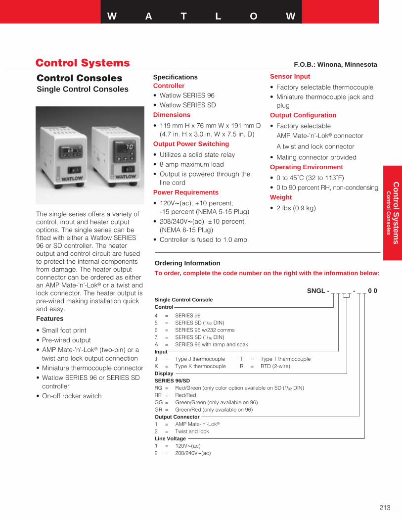
W A T L O W
213
Co
ntro
l System
s C
on
trol C
on
soles
Control SystemsControl ConsolesSingle Control Consoles
F.O.B.: Winona, Minnesota
Ordering Information
To order, complete the code number on the right with the information below:
SNGL - _ _ _ _ - _ _ 0 0Single Control ConsoleControl
4 = SERIES 965 = SERIES SD (1/32 DIN)6 = SERIES 96 w/232 comms7 = SERIES SD (1/16 DIN)A = SERIES 96 with ramp and soakInputJ = Type J thermocouple T = Type T thermocoupleK = Type K thermocouple R = RTD (2-wire)DisplaySERIES 96/SDRG = Red/Green (only color option available on SD (1/32 DIN)RR = Red/RedGG = Green/Green (only available on 96)GR = Green/Red (only available on 96)Output Connector1 = AMP Mate-’n’-Lok®
2 = Twist and lockLine Voltage1 = 120VÅ(ac)2 = 208/240VÅ(ac)
The single series offers a variety ofcontrol, input and heater outputoptions. The single series can befitted with either a Watlow SERIES96 or SD controller. The heateroutput and control circuit are fusedto protect the internal componentsfrom damage. The heater outputconnector can be ordered as eitheran AMP Mate-’n’-Lok® or a twist andlock connector. The heater output ispre-wired making installation quickand easy.Features
• Small foot print• Pre-wired output• AMP Mate-’n’-Lok® (two-pin) or a
twist and lock output connection• Miniature thermocouple connector• Watlow SERIES 96 or SERIES SD
controller• On-off rocker switch
SpecificationsController • Watlow SERIES 96• Watlow SERIES SDDimensions
• 119 mm H x 76 mm W x 191 mm D(4.7 in. H x 3.0 in. W x 7.5 in. D)
Output Power Switching
• Utilizes a solid state relay• 8 amp maximum load• Output is powered through the
line cordPower Requirements
• 120VÅ(ac), +10 percent, -15 percent (NEMA 5-15 Plug)
• 208/240VÅ(ac), ±10 percent,(NEMA 6-15 Plug)
• Controller is fused to 1.0 amp
Sensor Input
• Factory selectable thermocouple• Miniature thermocouple jack and
plugOutput Configuration
• Factory selectableAMP Mate-’n’-Lok® connector
A twist and lock connector
• Mating connector providedOperating Environment
• 0 to 45˚C (32 to 113˚F)• 0 to 90 percent RH, non-condensingWeight
• 2 lbs (0.9 kg)
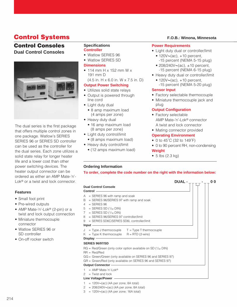
Control ConsolesDual Control Consoles
214
Control Systems
Ordering Information
To order, complete the code number on the right with the information below:
DUAL - _ _ _ _ - _ _ 0 0Dual Control ConsoleControl
A = SERIES 96 with ramp and soakB = SERIES 96/SERIES 97 with ramp and soak4 = SERIES 965 = SERIES SD (1/32 DIN)7 = SERIES SD (1/16 DIN)8 = SERIES 96/SERIES 97 controller/limit9 = SERIES SD6C/SERIES SD6L controller/limitInput
J = Type J thermocouple T = Type T thermocoupleK = Type K thermocouple R = RTD (2-wire)Display
SERIES 96/97/SD
RG = Red/Green (only color option available on SD (1/32 DIN)RR = Red/RedGG= Green/Green (only available on SERIES 96 and SERIES 97)GR = Green/Red (only available on SERIES 96 and SERIES 97)Output Connector
1 = AMP Mate-’n’-Lok®
2 = Twist and lockLine Voltage/Power
1 = 120VÅ(ac) (4A per zone; 8A total)2 = 208/240VÅ(ac) (4A per zone; 8A total)3 = 120VÅ(ac) (4A per zone; 16A total)
The dual series is the first packagethat offers multiple control zones inone package. Watlow’s SERIESSERIES 96 or SERIES SD controllercan be used as the controller forthe dual series. Each zone utilizes asolid state relay for longer heaterlife and a lower cost than otherpower switching devices. Theheater output connector can beordered as either an AMP Mate-’n’-Lok® or a twist and lock connector.
Features
• Small foot print• Pre-wired outputs• AMP Mate-’n’-Lok® (2-pin) or a
twist and lock output connection• Miniature thermocouple
connector• Watlow SERIES 96 or
SD controller• On-off rocker switch
SpecificationsController • Watlow SERIES 96• Watlow SERIES SDDimensions• 114 mm H x 152 mm W x
191 mm D(4.5 in. H x 6.0 in. W x 7.5 in. D)
Output Power Switching • Utilizes solid state relays• Output is powered through
line cord• Light duty dual
• 8 amp maximum load (4 amps per zone)
• Heavy duty dual• 16 amp maximum load
(8 amps per zone)• Light duty control/limit
• (8 amps maximum load)• Heavy duty control/limit
• (12 amps maximum load)
Power Requirements • Light duty dual or controller/limit
• 120VÅ(ac), +10 percent, -15 percent (NEMA 5-15 plug)
• 208/240VÅ(ac), ±10 percent, -15 percent (NEMA 6-15 plug)
• Heavy duty dual or controller/limit• 120VÅ(ac), +10 percent,
-15 percent (NEMA 5-20 plug)Sensor Input• Factory selectable thermocouple• Miniature thermocouple jack and
plugOutput Configuration• Factory selectable
AMP Mate-’n’-Lok® connectorA twist and lock connector
• Mating connector providedOperating Environment• 0 to 45˚C (32 to 149˚F)• 0 to 90 percent RH, non-condensingWeight• 5 lbs (2.3 kg)
F.O.B.: Winona, Minnesota
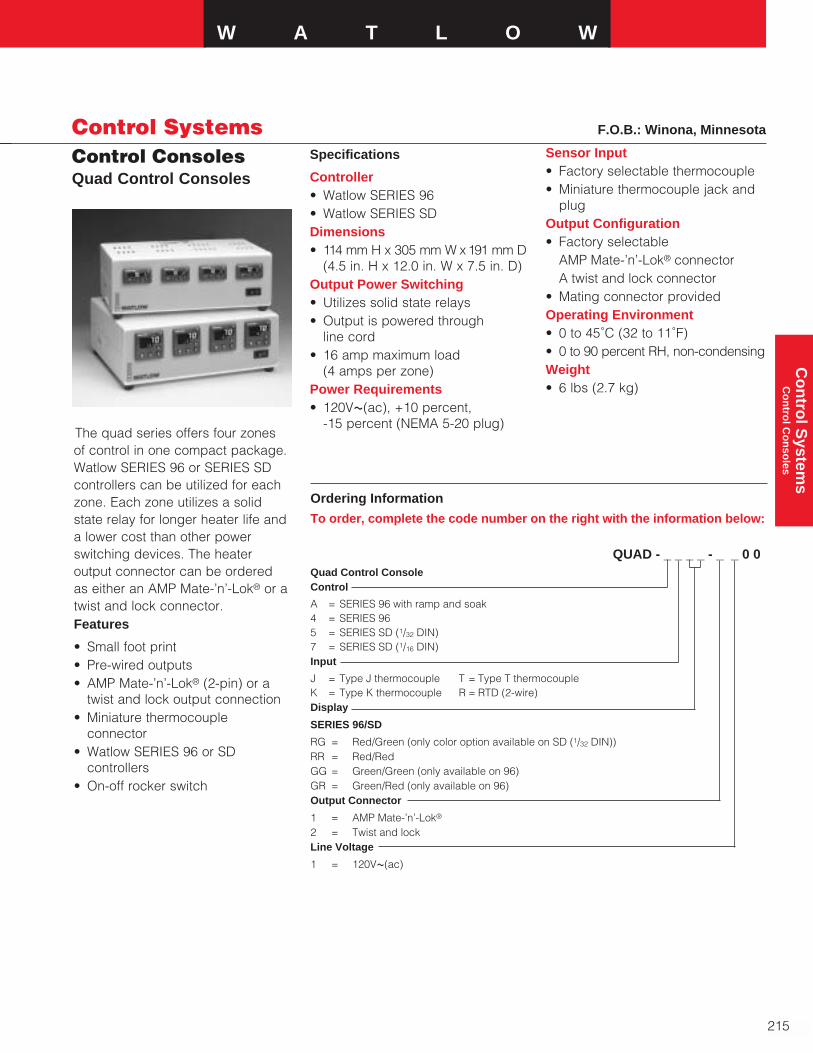
Control ConsolesQuad Control Consoles
W A T L O W
215
Co
ntro
l System
s C
on
trol C
on
soles
Control Systems
Ordering Information
To order, complete the code number on the right with the information below:
QUAD - _ _ _ _ - _ _ 0 0Quad Control ConsoleControl
A = SERIES 96 with ramp and soak4 = SERIES 965 = SERIES SD (1/32 DIN)7 = SERIES SD (1/16 DIN)Input
J = Type J thermocouple T = Type T thermocoupleK = Type K thermocouple R = RTD (2-wire)Display
SERIES 96/SD
RG = Red/Green (only color option available on SD (1/32 DIN))RR = Red/RedGG = Green/Green (only available on 96)GR = Green/Red (only available on 96)Output Connector
1 = AMP Mate-’n’-Lok®
2 = Twist and lockLine Voltage
1 = 120VÅ(ac)
Specifications
Controller• Watlow SERIES 96• Watlow SERIES SDDimensions• 114 mm H x 305 mm W x 191 mm D
(4.5 in. H x 12.0 in. W x 7.5 in. D)Output Power Switching• Utilizes solid state relays• Output is powered through
line cord• 16 amp maximum load
(4 amps per zone)Power Requirements • 120VÅ(ac), +10 percent,
-15 percent (NEMA 5-20 plug)The quad series offers four zonesof control in one compact package.Watlow SERIES 96 or SERIES SDcontrollers can be utilized for eachzone. Each zone utilizes a solidstate relay for longer heater life anda lower cost than other powerswitching devices. The heateroutput connector can be orderedas either an AMP Mate-’n’-Lok® or atwist and lock connector.Features
• Small foot print• Pre-wired outputs• AMP Mate-’n’-Lok® (2-pin) or a
twist and lock output connection• Miniature thermocouple
connector• Watlow SERIES 96 or SD
controllers• On-off rocker switch
Sensor Input• Factory selectable thermocouple• Miniature thermocouple jack and
plugOutput Configuration• Factory selectable
AMP Mate-’n’-Lok® connectorA twist and lock connector
• Mating connector providedOperating Environment• 0 to 45˚C (32 to 11˚F)• 0 to 90 percent RH, non-condensingWeight• 6 lbs (2.7 kg)
F.O.B.: Winona, Minnesota
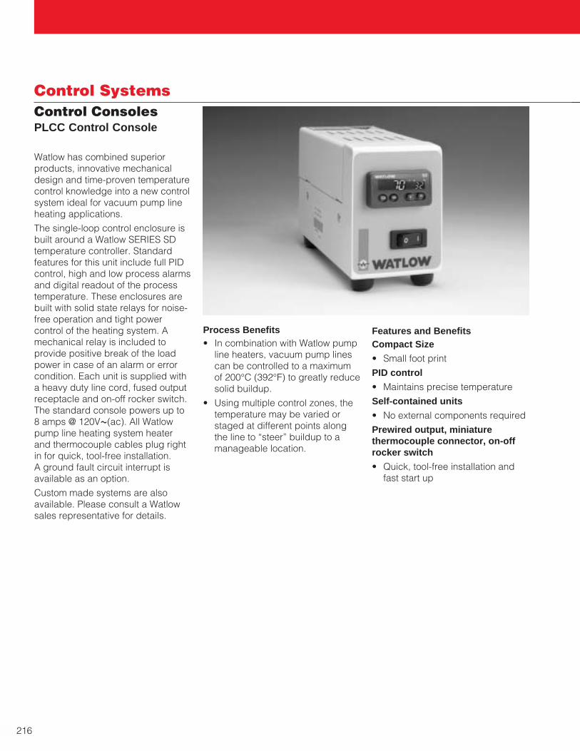
216
Control SystemsControl ConsolesPLCC Control Console
Watlow has combined superiorproducts, innovative mechanicaldesign and time-proven temperaturecontrol knowledge into a new controlsystem ideal for vacuum pump lineheating applications.
The single-loop control enclosure isbuilt around a Watlow SERIES SDtemperature controller. Standardfeatures for this unit include full PIDcontrol, high and low process alarmsand digital readout of the processtemperature. These enclosures arebuilt with solid state relays for noise-free operation and tight powercontrol of the heating system. Amechanical relay is included toprovide positive break of the loadpower in case of an alarm or errorcondition. Each unit is supplied witha heavy duty line cord, fused outputreceptacle and on-off rocker switch.The standard console powers up to8 amps @ 120VÅ(ac). All Watlowpump line heating system heaterand thermocouple cables plug rightin for quick, tool-free installation. A ground fault circuit interrupt isavailable as an option.
Custom made systems are alsoavailable. Please consult a Watlowsales representative for details.
Process Benefits• In combination with Watlow pump
line heaters, vacuum pump linescan be controlled to a maximumof 200°C (392°F) to greatly reducesolid buildup.
• Using multiple control zones, thetemperature may be varied orstaged at different points alongthe line to “steer” buildup to amanageable location.
Features and BenefitsCompact Size
• Small foot print
PID control
• Maintains precise temperature
Self-contained units
• No external components required
Prewired output, miniaturethermocouple connector, on-offrocker switch
• Quick, tool-free installation andfast start up

W A T L O W
217
Co
ntro
l System
s C
on
trol C
on
soles
Control SystemsControl ConsolesPLCC Control Console
Specifications
Controller• Watlow SERIES SD 1⁄32 DIN
Sensor Input• Type K or Type J thermocouple,
factory selectable
• Miniature type thermocouple jack
• Mates with Watlow pump linethermocouples
Heater Output• Solid state relay power control
• Maximum 8 amps @ 120VÅ(ac),fused at 10A
• Amp Universal Mate-N-Lok®
connector, 3-position
• Mates with Watlow pump lineheaters
Alarm Output • Disconnects power to heaters
when tripped
• Alarm signal via 5 amp contactclosure
• Amp Universal Mate-N-Lok®
connector, 2-position
• Alarm set points adjustable
Power Requirements• 120VÅ(ac) (+10 percent -15
percent, 50/60Hz)
• IDE style fused input powerreceptacle with six foot longpower cord
• On-off rocker switch
• Optional GFCI line cord available
• Data retention upon power failurevia non-volatile memory
Extension Cables• Heater Power Extension Cable:
Type SJ, 16-3 stranded.Enclosure connection: AmpUniversal Mate-N-Lok® connector,3-position. Heater connection:Amp Universal Mate-N-Lok®
connector, 2-position, withseparate ring terminal ground.
Ordering Information
To order, complete the code number on the right with the information below:
P L C C - — — — — - 0 0 — —SERIES PLCC = Control console with single thermocouple control input, 8A heater control output, contact alarm output
Input Type
J = Type J thermocouple
K = Type K thermocouple
Extension Cable Length* (ft)
00 = None
05 = 5 ft
10 = 10 ft (standard length)
15 = 15 ft
25 = 25 ft
Power Options
0 = Standard line cord
G = GFCI line cord
Custom Options
00 = None
AA - ZZ = Consult factory for options
* Includes both heater and thermocouple cables
• Thermocouple Extension Cable:FEP Teflon® insulated, 24 Gastranded. Enclosure connection:miniature type thermocouple plug.Sensor connection: miniature typethermocouple jack. Calibration asspecified
Mechanical• Overall Dimensions: 76.2 mm W x
114.3 mm H x 178 mm D (3 in. W x 4.5 in. H x 7 in. D)
• Weight: Approx. 1.7 lbs
• Table-top style rubber mountingfeet
Operating Environment• Ambient temperature: 0 - 45°C
(32 - 113°F)
• 0 - 90 percent RH, non-condensing
Teflon® is a registered trademark of E.I.du Pont de Nemours & Company

218
Control SystemsControl Boxes
Model 1 4 Metal 12 12 6 12.75 104X Fiberglass 12 10 6 12.9375 8
Model 2 4 Metal 12 14.375 6 12.75 104X Fiberglass 10 8 6 10.9375 6
To complete or upgrade a heaterinstallation, Watlow offers complete,ready-to-install control boxes. Threebasic models save time and hassleby allowing customers to specifycontroller and power switchingdevices to meet application objectives.
Control Box ConfigurationsModel 1—Process and high-limitcontrollersModel 2—Process or high-limitcontrollersCapable of switching up to 50 ampsand 480VÅ(ac), each control boxcomes pre-wired with customerspecified options.
Fast ShipmentAll configurable control boxes shipwithin five to 10 working days.
Enclosure Options➀
• Moisture resistant steel (NEMA 4)• Corrosion resistant fiberglass
(NEMA 4X)
Controller Options➀
• PID auto-tuning SERIES SD and96 with ramp-to-set point
• On-off SERIES CV controllers• High-limit protection SERIES LV
and 97
Power Switching Options➀
• Electromechanical relay (contactor)➁
• E-SAFE® RELAYS• SCR DIN-A-MITEs®
AvailabilityAssembly Stock: Five to 10 workingdays
Modified Stock➃ : Five to 10 workingdays
Made-to-Order: 15 working days
Options, complexity and quantitymay affect availability and lead-times. Consult factory.
➀ Consult specific model option information for availability.➁ Electromechanical relays are not recommended for PID control. They are warranted for only
100,000 contact closures.➂ Application at stated ampacity is sensitive to ambient temperature.➃ Assembly Stock units with catalog options.
Control NEMABox Enclosure Enclosure Dimensions (in.)
Rating Material A B C G H
Control Box Dimensions
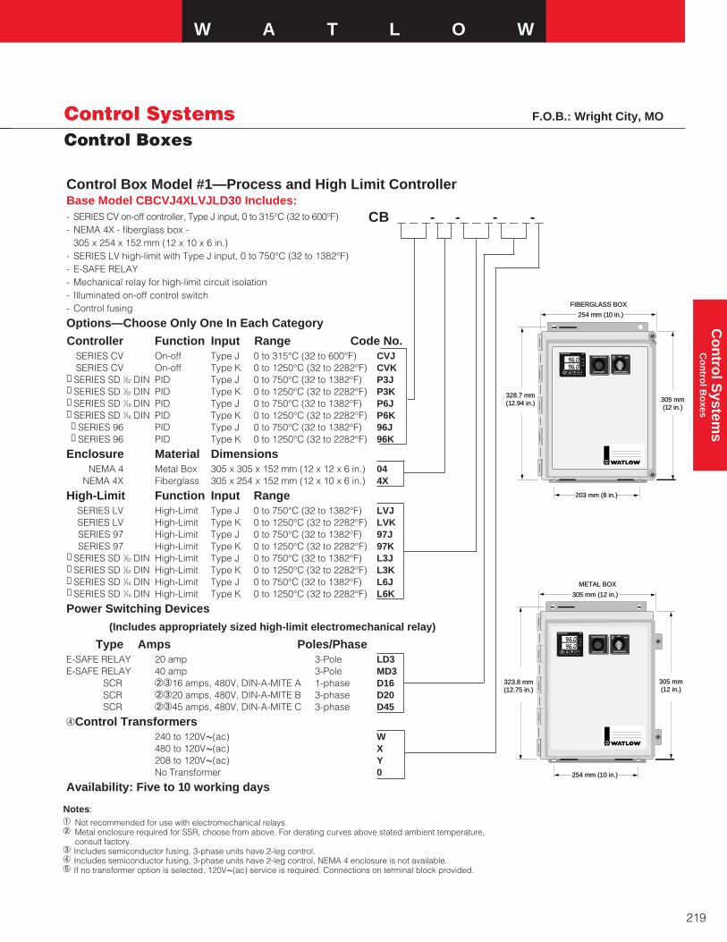
Control Box Model #1—Process and High Limit ControllerBase Model CBCVJ4XLVJLD30 Includes:- SERIES CV on-off controller, Type J input, 0 to 315°C (32 to 600°F)- NEMA 4X - fiberglass box -
305 x 254 x 152 mm (12 x 10 x 6 in.)- SERIES LV high-limit with Type J input, 0 to 750°C (32 to 1382°F)- E-SAFE RELAY- Mechanical relay for high-limit circuit isolation- Illuminated on-off control switch- Control fusing
Options—Choose Only One In Each Category
Controller Function Input Range Code No.SERIES CV On-off Type J 0 to 315°C (32 to 600°F) CVJSERIES CV On-off Type K 0 to 1250°C (32 to 2282°F) CVK
➀ SERIES SD 1⁄32 DIN PID Type J 0 to 750°C (32 to 1382°F) P3J➀ SERIES SD 1⁄32 DIN PID Type K 0 to 1250°C (32 to 2282°F) P3K➀ SERIES SD 1⁄16 DIN PID Type J 0 to 750°C (32 to 1382°F) P6J➀ SERIES SD 1⁄16 DIN PID Type K 0 to 1250°C (32 to 2282°F) P6K➀ SERIES 96 PID Type J 0 to 750°C (32 to 1382°F) 96J➀ SERIES 96 PID Type K 0 to 1250°C (32 to 2282°F) 96K
Enclosure Material DimensionsNEMA 4 Metal Box 305 x 305 x 152 mm (12 x 12 x 6 in.) 04
NEMA 4X Fiberglass 305 x 254 x 152 mm (12 x 10 x 6 in.) 4X
High-Limit Function Input RangeSERIES LV High-Limit Type J 0 to 750°C (32 to 1382°F) LVJSERIES LV High-Limit Type K 0 to 1250°C (32 to 2282°F) LVKSERIES 97 High-Limit Type J 0 to 750°C (32 to 1382°F) 97JSERIES 97 High-Limit Type K 0 to 1250°C (32 to 2282°F) 97K
➀ SERIES SD 1⁄32 DIN High-Limit Type J 0 to 750°C (32 to 1382°F) L3J➀ SERIES SD 1⁄32 DIN High-Limit Type K 0 to 1250°C (32 to 2282°F) L3K➀ SERIES SD 1⁄16 DIN High-Limit Type J 0 to 750°C (32 to 1382°F) L6J➀ SERIES SD 1⁄16 DIN High-Limit Type K 0 to 1250°C (32 to 2282°F) L6K
Power Switching Devices
(Includes appropriately sized high-limit electromechanical relay)
Type Amps Poles/PhaseE-SAFE RELAY 20 amp 3-Pole LD3E-SAFE RELAY 40 amp 3-Pole MD3
SCR bc16 amps, 480V, DIN-A-MITE A 1-phase D16SCR bc20 amps, 480V, DIN-A-MITE B 3-phase D20SCR bc45 amps, 480V, DIN-A-MITE C 3-phase D45
dControl Transformers240 to 120VÅ(ac) W480 to 120VÅ(ac) X208 to 120VÅ(ac) YNo Transformer 0
Availability: Five to 10 working days
W A T L O W
219
Co
ntro
l System
s C
on
trol B
oxes
Control SystemsControl Boxes
CB _ _ _-_ _-_ _ _-_ _ _-_
METAL BOXMETAL BOX
305 mm (12 in.)305 mm (12 in.)
254 mm (10 in.)254 mm (10 in.)
323.8 mm323.8 mm(12.75 in.)(12.75 in.)
305 mm305 mm(12 in.)(12 in.)
OFFOFFSETSETUPUP
RUNRUN
CONTROL CIRCUITCONTROL CIRCUIT
HI-LIMIT CONDITIONHI-LIMIT CONDITION
PUSH TO ALERTPUSH TO ALERT
93
FIBERGLASS BOXFIBERGLASS BOX
254 mm (1254 mm (10 in.)0 in.)
203 mm (8 in.)203 mm (8 in.)
328.7 mm328.7 mm(12.94 in.)2.94 in.) 305 mm305 mm
(12 in.)2 in.)
OFFOFFSETSETUPUP
RUNRUN
CONTROL CIRCUITCONTROL CIRCUIT
HI-LIMIT CONDITIONHI-LIMIT CONDITION
PUSH TO ALERTPUSH TO ALERT
93
Notes:a Not recommended for use with electromechanical relays.b Metal enclosure required for SSR, choose from above. For derating curves above stated ambient temperature,
consult factory.c Includes semiconductor fusing, 3-phase units have 2-leg control.d Includes semiconductor fusing, 3-phase units have 2-leg control, NEMA 4 enclosure is not available.e If no transformer option is selected, 120VÅ(ac) service is required. Connections on terminal block provided.
F.O.B.: Wright City, MO
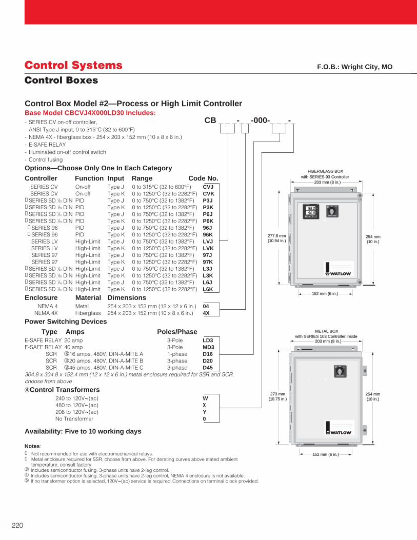
220
Control SystemsControl Boxes
Control Box Model #2—Process or High Limit ControllerBase Model CBCVJ4X000LD30 Includes:- SERIES CV on-off controller,
ANSI Type J input, 0 to 315°C (32 to 600°F)- NEMA 4X - fiberglass box - 254 x 203 x 152 mm (10 x 8 x 6 in.)- E-SAFE RELAY- Illuminated on-off control switch- Control fusing
Options—Choose Only One In Each Category
Controller Function Input Range Code No.SERIES CV On-off Type J 0 to 315°C (32 to 600°F) CVJSERIES CV On-off Type K 0 to 1250°C (32 to 2282°F) CVK
➀ SERIES SD 1⁄32 DIN PID Type J 0 to 750°C (32 to 1382°F) P3J➀ SERIES SD 1⁄32 DIN PID Type K 0 to 1250°C (32 to 2282°F) P3K➀ SERIES SD 1⁄16 DIN PID Type J 0 to 750°C (32 to 1382°F) P6J➀ SERIES SD 1⁄16 DIN PID Type K 0 to 1250°C (32 to 2282°F) P6K➀ SERIES 96 PID Type J 0 to 750°C (32 to 1382°F) 96J➀ SERIES 96 PID Type K 0 to 1250°C (32 to 2282°F) 96K
SERIES LV High-Limit Type J 0 to 750°C (32 to 1382°F) LVJSERIES LV High-Limit Type K 0 to 1250°C (32 to 2282°F) LVKSERIES 97 High-Limit Type J 0 to 750°C (32 to 1382°F) 97JSERIES 97 High-Limit Type K 0 to 1250°C (32 to 2282°F) 97K
➀ SERIES SD 1⁄32 DIN High-Limit Type J 0 to 750°C (32 to 1382°F) L3J➀ SERIES SD 1⁄32 DIN High-Limit Type K 0 to 1250°C (32 to 2282°F) L3K➀ SERIES SD 1⁄16 DIN High-Limit Type J 0 to 750°C (32 to 1382°F) L6J➀ SERIES SD 1⁄16 DIN High-Limit Type K 0 to 1250°C (32 to 2282°F) L6K
Enclosure Material DimensionsNEMA 4 Metal 254 x 203 x 152 mm (12 x 12 x 6 in.) 04
NEMA 4X Fiberglass 254 x 203 x 152 mm (10 x 8 x 6 in.) 4X
Power Switching Devices
Type Amps Poles/PhaseE-SAFE RELAY 20 amp 3-Pole LD3E-SAFE RELAY 40 amp 3-Pole MD3
SCR c16 amps, 480V, DIN-A-MITE A 1-phase D16SCR c20 amps, 480V, DIN-A-MITE B 3-phase D20SCR c45 amps, 480V, DIN-A-MITE C 3-phase D45
304.8 x 304.8 x 152.4 mm (12 x 12 x 6 in.) metal enclosure required for SSR and SCR, choose from above
dControl Transformers240 to 120VÅ(ac) W480 to 120VÅ(ac) X208 to 120VÅ(ac) YNo Transformer 0
Availability: Five to 10 working days
CB _ _ _-_ _-000-_ _ _-_
FIBERGLASS BOXFIBERGLASS BOXwith SERIES 93 Controllerwith SERIES 93 Controller
203 mm (8 in.)203 mm (8 in.)
152 mm (6 in.)52 mm (6 in.)
277.8 mm277.8 mm(1(10.94 in.)0.94 in.)
254 mm254 mm(1(10 in.)0 in.)
MODEL #2 FIBERGLASS 965
OFFOFFSETSETUPUP
RUNRUN
CONTROL CIRCUITCONTROL CIRCUIT
93
METMETAL BOXAL BOXwith SERIES 103 Controller insidewith SERIES 103 Controller inside
203 mm (8 in.)203 mm (8 in.)
273 mm273 mm(1(10.75 in.)0.75 in.)
152 mm (6 in.)52 mm (6 in.)
254 mm254 mm(1(10 in.)0 in.)
OFFOFFSETSETUPUP
RUNRUN
CONTROL CIRCUITCONTROL CIRCUIT
Notes:➀ Not recommended for use with electromechanical relays.➁ Metal enclosure required for SSR, choose from above. For derating curves above stated ambient
temperature, consult factory.c Includes semiconductor fusing, 3-phase units have 2-leg control.d Includes semiconductor fusing, 3-phase units have 2-leg control, NEMA 4 enclosure is not available.e If no transformer option is selected, 120VÅ(ac) service is required.Connections on terminal block provided.
F.O.B.: Wright City, MO

W A T L O W
221
Co
ntro
l Accesso
ries T
herm
ostats an
d A
ccessories
Control AccessoriesThermostats andAccessoriesThermostats regulate temperature innon-critical applications. They sensetemperature, within a preset rangeand cycle heaters on and off tomaintain the set point.
Thermostats may be mounted insidea terminal enclosure or remotemounted (separate from the heaterassembly). If using a remotemounted thermostat, be sure toorder sufficient capillary tube lengthto permit installation.
All Watlow thermostats are normallyclosed circuit and either single-pole,single throw (SPST) or double-pole,single throw (DPST). They can beused with or without an enclosure.
Thermostat selection should bebased on temperature range, capillary tube length and sensorbulb size (diameter/length).
Remote Mount ThermostatAssembliesRemote mounted thermostat assemblies can be supplied with thefollowing enclosures:
• General purpose (NEMA 1)
• Moisture resistant (NEMA 4)
• Explosion resistant (NEMA 7)
• Explosion/moisture resistant(NEMA 7/4)
• Dust resistant (NEMA 12)
Pilot LightAn optional pilot light gives visualindication whether the power supplied to the heating element(s) ison or off. To order, please specifysuffix code PL11.
Thermostat Conversion KitsKits are available to convert aheater’s general purpose (NEMA 1)terminal enclosure to accept either asingle or double pole thermostat.The kit contains all the necessaryparts to change out the existing terminal enclosure cover and mountthe thermostat inside. These arehardware and wiring kits only.
Single pole conversion kit covers25.4, 31.75, 50.8 and 63.5 mm(1.125, 2 and 2.5 in.) NPT screwplugs. To order, specify code. K492-000-35-(thermostat type).See Watlow’s Heater catalog, page425 for type.
Double pole conversion kit covers50.8 and 63.5 mm (2 and 2.5 in.)inch NPT screw plugs. To order,specify code K492-000-34-(thermostat type). See Watlow’sHeater catalog, page 425 for type.
Celsius Dial ScaleThermostats are shipped withFahrenheit (°F) dial scales. If yourapplication requires a Celsius (°C)scale, order the optional dial face.
To order, specify code CD. Scalewill match thermostat temperaturerange.
Incoloy® is a registered trademark of the SpecialMetals Corporation.
Thermostats with Enclosures
83 mm(3.25 in.)
55 mm(2.156 in.)
148 mm(5.812 in.)
84 mm(3.312 in.)
167 mm(6.562 in.)
167 mm(6.562 in.)
152 mm(6 in.)
108 mm(4.25 in.)
NEMA 1 Single and Double-Pole NEMA 4 and 12 Single-Pole
NEMA 7 Single-Pole
NEMA 4 and 12 Double-Pole NEMA 7 Double-Pole197 mm(7.75 in.)
165 mm(6.5 in.)
152 mm(6 in.)
164 mm(6.25 in.)
11 mm(0.437 in.)
220 mm(8.75 in.)
13 mm (0.5 in.)
178 mm(7 in.)
117 mm(4.625 in.)
135 mm(5.937 in.)162 mm
(6.375 in.)
56 mm(2.5 in.)
56 mm(2.812 in.)
76 mm(32 in.)
83 mm(3.25 in.)
88 mm(0.437 in.)
View Above Shown Without Cover
75 mm(2.937 in.)
(2) 6 mm (0.218 in.) Dia. Holes
112 mm(4.375 in.)
70 mm (2.75 in.)
91 mm(3.187 in.)
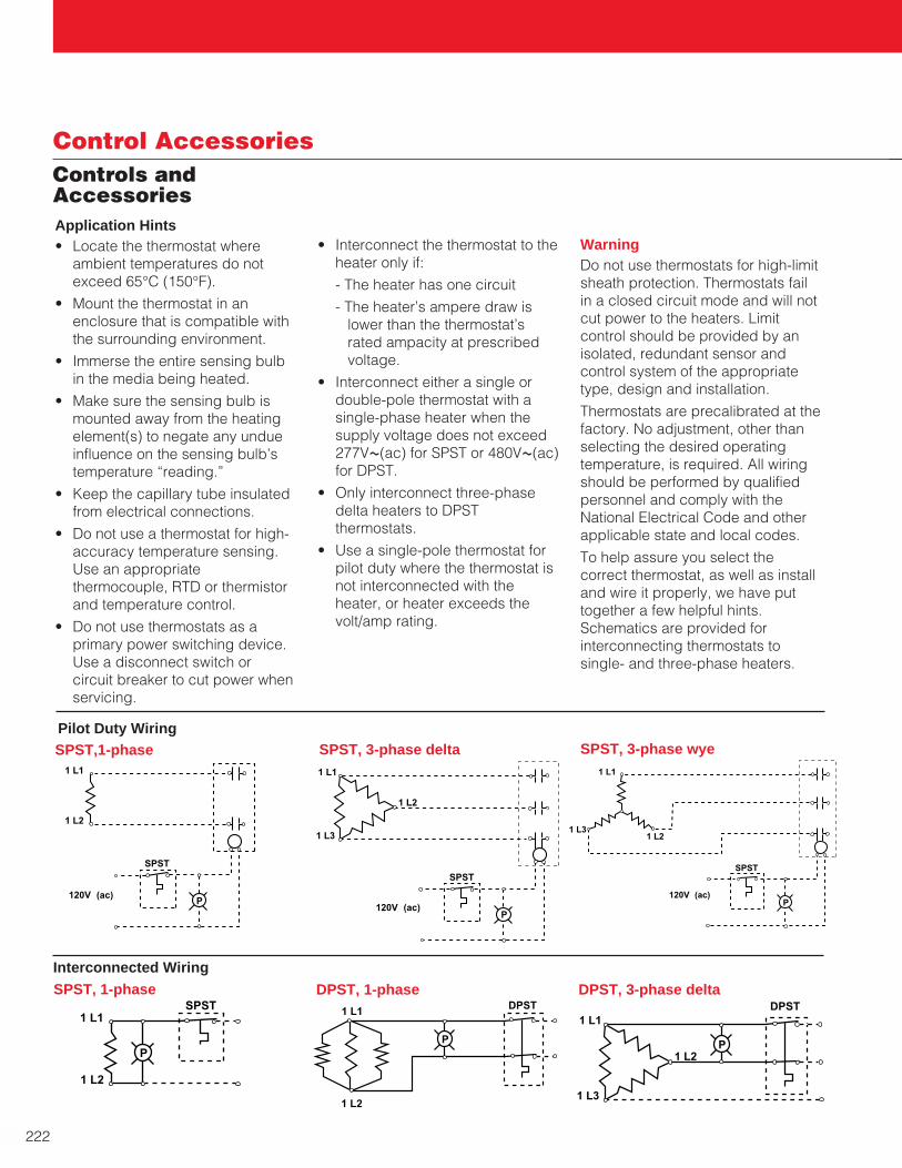
222
Control AccessoriesControls andAccessoriesApplication Hints• Locate the thermostat where
ambient temperatures do notexceed 65°C (150°F).
• Mount the thermostat in an enclosure that is compatible withthe surrounding environment.
• Immerse the entire sensing bulbin the media being heated.
• Make sure the sensing bulb ismounted away from the heatingelement(s) to negate any undueinfluence on the sensing bulb’stemperature “reading.”
• Keep the capillary tube insulatedfrom electrical connections.
• Do not use a thermostat for high-accuracy temperature sensing.Use an appropriatethermocouple, RTD or thermistorand temperature control.
• Do not use thermostats as a primary power switching device.Use a disconnect switch or circuit breaker to cut power whenservicing.
• Interconnect the thermostat to theheater only if:
- The heater has one circuit
- The heater’s ampere draw islower than the thermostat’srated ampacity at prescribedvoltage.
• Interconnect either a single ordouble-pole thermostat with asingle-phase heater when thesupply voltage does not exceed277VÅ(ac) for SPST or 480VÅ(ac)for DPST.
• Only interconnect three-phasedelta heaters to DPST thermostats.
• Use a single-pole thermostat forpilot duty where the thermostat isnot interconnected with theheater, or heater exceeds thevolt/amp rating.
WarningDo not use thermostats for high-limitsheath protection. Thermostats failin a closed circuit mode and will notcut power to the heaters. Limitcontrol should be provided by anisolated, redundant sensor andcontrol system of the appropriatetype, design and installation.
Thermostats are precalibrated at thefactory. No adjustment, other thanselecting the desired operating temperature, is required. All wiringshould be performed by qualifiedpersonnel and comply with theNational Electrical Code and otherapplicable state and local codes.
To help assure you select the correct thermostat, as well as installand wire it properly, we have puttogether a few helpful hints.Schematics are provided for interconnecting thermostats to single- and three-phase heaters.
1 L1
1 L2
P
SPST
120V(ac)
1 L1
1 L3
1 L2
P
SPST
120V(ac)
1 L1
1 L31 L2
P
SPST
120V(ac)
1 L1
1 L2
SPST
P
1 L1
1 L2
DPST
P
1 L1
1 L3
1 L2P
DPST
SPST, 3-phase wyeSPST, 3-phase deltaSPST,1-phase
DPST, 3-phase deltaDPST, 1-phaseSPST, 1-phase
Pilot Duty Wiring
Interconnected Wiring
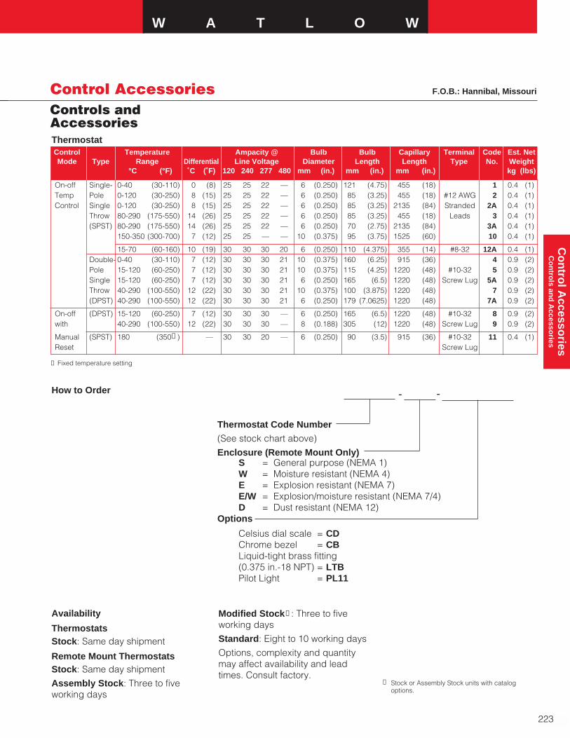
W A T L O W
223
Co
ntro
l Accesso
ries C
on
trols an
d A
ccessories
Control AccessoriesControls andAccessories
On-off Single- 0-40 (30-110) 0 (8) 25 25 22 — 6 (0.250) 121 (4.75) 455 (18) 1 0.4 (1)Temp Pole 0-120 (30-250) 8 (15) 25 25 22 — 6 (0.250) 85 (3.25) 455 (18) #12 AWG 2 0.4 (1)Control Single 0-120 (30-250) 8 (15) 25 25 22 — 6 (0.250) 85 (3.25) 2135 (84) Stranded 2A 0.4 (1)
Throw 80-290 (175-550) 14 (26) 25 25 22 — 6 (0.250) 85 (3.25) 455 (18) Leads 3 0.4 (1)(SPST) 80-290 (175-550) 14 (26) 25 25 22 — 6 (0.250) 70 (2.75) 2135 (84) 3A 0.4 (1)
150-350 (300-700) 7 (12) 25 25 — — 10 (0.375) 95 (3.75) 1525 (60) 10 0.4 (1)
15-70 (60-160) 10 (19) 30 30 30 20 6 (0.250) 110 (4.375) 355 (14) #8-32 12A 0.4 (1)Double- 0-40 (30-110) 7 (12) 30 30 30 21 10 (0.375) 160 (6.25) 915 (36) 4 0.9 (2)Pole 15-120 (60-250) 7 (12) 30 30 30 21 10 (0.375) 115 (4.25) 1220 (48) #10-32 5 0.9 (2)Single 15-120 (60-250) 7 (12) 30 30 30 21 6 (0.250) 165 (6.5) 1220 (48) Screw Lug 5A 0.9 (2)Throw 40-290 (100-550) 12 (22) 30 30 30 21 10 (0.375) 100 (3.875) 1220 (48) 7 0.9 (2)(DPST) 40-290 (100-550) 12 (22) 30 30 30 21 6 (0.250) 179 (7.0625) 1220 (48) 7A 0.9 (2)
On-off (DPST) 15-120 (60-250) 7 (12) 30 30 30 — 6 (0.250) 165 (6.5) 1220 (48) #10-32 8 0.9 (2)with 40-290 (100-550) 12 (22) 30 30 30 — 8 (0.188) 305 (12) 1220 (48) Screw Lug 9 0.9 (2)
Manual (SPST) 180 (350➀ ) — 30 30 20 — 6 (0.250) 90 (3.5) 915 (36) #10-32 11 0.4 (1)Reset Screw Lug
Thermostat Code Number
(See stock chart above)
Enclosure (Remote Mount Only)S = General purpose (NEMA 1)W = Moisture resistant (NEMA 4)E = Explosion resistant (NEMA 7)E/W = Explosion/moisture resistant (NEMA 7/4)D = Dust resistant (NEMA 12)
Options
Celsius dial scale = CDChrome bezel = CBLiquid-tight brass fitting(0.375 in.-18 NPT) = LTBPilot Light = PL11
Control Temperature Ampacity @ Bulb Bulb Capillary Terminal Code Est. NetMode Type Range Differential Line Voltage Diameter Length Length Type No. Weight
°C (°F) ˚C (˚F) 120 240 277 480 mm (in.) mm (in.) mm (in.) kg (lbs)
➀ Fixed temperature setting
Thermostat
Availability
ThermostatsStock: Same day shipment
Remote Mount ThermostatsStock: Same day shipment
Assembly Stock: Three to fiveworking days
Modified Stock➁ : Three to fiveworking days
Standard: Eight to 10 working days
Options, complexity and quantitymay affect availability and leadtimes. Consult factory.
➁ Stock or Assembly Stock units with catalogoptions.
F.O.B.: Hannibal, Missouri
How to Order - -

224
Control AccessoriesSensors andAccessories
305 (12) PWS12 0.5 (1)Steel 610 (24) PWS24 1.0 (2)
915 (36) PWS36 1.0 (2)
Stainless 305 (12) PWSS12 0.5 (1)Steel 610 (24) PWSS24 1.0 (2)
915 (36) PWSS36 1.0 (2)
Plug and Immersed Est. Ship.Thermowell B Dimension Code No. Weight
Material mm (in.) kg (lb)
Low Liquid Level SensorThe Watlow low liquid level sensorcan protect a heating system bysensing when a liquid drops below a predetermined level. This isaccomplished by locating the sensorat the minimum desired liquid levelin the tank or vessel. The sensor’sANSI Type J thermocouple outputcan be connected to a variety ofcontrols, alarms and limit protectiondevices.
To provide an additional margin ofprotection, the Type J thermocouplemakes this low liquid level sensorrespond considerably faster thanconventional capillary bulb thermostats.
To order, specify code numberBCN5J1SJ.
Application Hints• Only use sensor in non-
flammable liquids that are compatible with the Incoloy®
sheath and 304 stainless steelscrew plug.
• Application should tolerate sheathtemperature at limit set point.
• The time delay between the low liquid level condition on-set,and the sensor’s ability to signalthe control device should beadequate to protect the heater(s).See Installation and MaintenanceInstructions for details.
Controller Recommendation• Use Watlow Safety Limit
Temperature Controller SERIES 142 (Code number 142A-3605-1300). This controllerfeatures compact sub-panelmounting and is sealed againstambient environment. UL®
recognized for limit protection(UL® 991, “Tests For Safety-Related Controls Employing SolidState Devices”).
Controller supplied by Watlow inWinona, Minnesota.
Specifications
Screw plug: 26 mm (1 in.) NPT
Plug material: 304 stainless steel
Sheath material: Incoloy®
Watt density: 13 W/in2 (2 W/cm2)
Watts: 100
Volts: 120VÅ(ac)
Immersed length: 140 mm (5.5 in.)
Thermocouple: ANSI Type J
Est. ship. wt.: 1 kg (2 lbs)
AvailabilityStock: Same day shipmentModified Stock➀ : Five to sevenworking daysMade-to-Order: Four to six weeksOptions, complexity and quantitymay affect availability and leadtimes. Consult factory.
Protective WellsProtective wells isolate and protectthermostat bulbs and othertemperature sensors (thermo-couples, RTDs or thermistors). Theyallow inserting the sensing elementsufficiently into the media beingheated without being damaged.
Steel or stainless steel protectivewells are available in three lengths.They are supplied with 13 mm (0.5 in.)NPT mounting and 10 mm (0.375 in.)-18 NPT internal thread for mating toa liquid-tight bushing (LTB).
All units are stock. To order, specifythe appropriate code number fromthe stock table.
➀ Stock units with catalog options.
AvailabilityStock: Same day shipmentModified Stock➁ : Five to sevenworking daysMade-to-Order: Three weeks
Options, complexity and quantitymay affect availability and leadtimes. Consult factory.
Protective Wells
➁ Stock units with catalog options.
Internal 10 mm (0.375 in.) - NPT 13 mm (0.5 in.) O.D.
13 mm (0.5 in.) NPTImmersed LengthB ± 6 mm (0.25 in.)
General Purpose (NEMA 1) Enclosure19 mm (0.75 in.) NPT Conduit Opening
13 mm (0.5 in.)No-Heat
13 mm(0.5 in.)
Dia.
140 mm (5.5 in.)
FIREROD®
Cartridge Heater
F.O.B.: Hannibal, Missouri

W A T L O W
225
• Solenoid coil/valve Solid state relay, Form A, • Mercury displacement relay (MDR) with RC suppression• Electromechanical relay• General purpose contactor
• AC input solid state relay (SSR) Solid state relay, Form A, • AC input solid state contactor without contact suppression• High impedance load, typ.≥ 5kΩ• Piezoelectric buzzer• Indicator lamps
• Various devices in on-off mode Electromechanical relay, Form A, with RC suppression
• Various devices in on-off mode (high Electromechanical relay, Form A, impedance or inductive devices with coils without contact suppressionsuppressed)
• Indicator lamps• Small heaters• AC input solid state contactor
• A safety limit circuit with contactor, Electromechanical relay, Form A or B,electromechanical relay or with RC suppression N/Amercury displacement relay (MDR)
• A safety limit circuit with contactor, Electromechanical relay, Form C,electromechanical relay or without RC suppression N/Amercury displacement relay (MDR)
• Various devices in on-off mode Electromechanical relay, Form A or B, • Indicator lamps without contact suppression• Small heaters• AC input solid state contactor
• Various devices in on-off mode Electromechanical relay, Form C, • Solenoid coil/valve with RC suppression• Mercury displacement relay (MDR)• Electromechanical relay• General purpose contactor• Pilot duty relays
• Various devices in on-off mode (high Electromechanical relay, Form C, impedance or inductive devices with coils without contact suppressionsuppressed)
• Indicator lamps• Small heaters• AC input solid state contactor
• DC input solid state relay (SSR) Switched dc, isolated• PLC-dc input• Low voltage panel lamp
• DC input solid state relay (SSR) Switched dc, non-isolated• PLC-dc input• Low voltage panel lamp
• DC input solid state relay (SSR) Open collector, isolated• PLC-dc input• Low voltage panel lamp
I want to switch… Output I want to control… Controller Output Life
Controller OutputComparison Guide
Co
ntro
ller Ou
tpu
tC
om
pariso
n G
uid
e
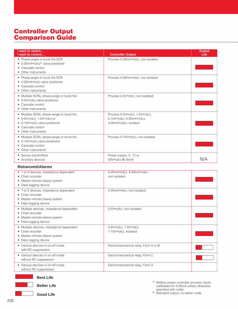
• Phase-angle or burst fire SCR Process 0-20mAÎ(dc), non-isolated• 0-20mAÎ(dc)a valve positioner• Cascade control• Other instruments
• Phase-angle or burst fire SCR Process 4-20mAÎ(dc), non-isolated• 4-20mAÎ(dc) valve positioner• Cascade control• Other instruments
• Multiple SCRs, phase-angle or burst fire Process 0-5VÎ(dc), non-isolated• 0-5VÎ(dc) valve positioner• Cascade control• Other instruments
• Multiple SCRs, phase-angle or burst fire Process 0-5VÎ(dc), 1-5VÎ(dc), • 0-5VÎ(dc), 1-5VÎ(dc) or 0-10VÎ(dc), 0-20mAÎ(dc), • 0-10VÎ(dc) valve positioner 4-20mAÎ(dc), isolated• Cascade control• Other instruments
• Multiple SCRs, phase-angle or burst fire Process 0-10VÎ(dc), non-isolated• 0-10VÎ(dc) valve positioner• Cascade control• Other instruments
• Sensor transmitters Power supply, 5, 12 or • Ancillary devices 20VÎ(dc) @ 30mA N/A
226
• 1 or 2 devices, impedance dependent 0-20mAÎ(dc), 4-20mAÎ(dc), • Chart recorder non-isolated• Master-remote (slave) system• Data logging device
• 1 or 2 devices, impedance dependent 4-20mAÎ(dc), non-isolated• Chart recorder• Master-remote (slave) system• Data logging device
• Multiple devices, impedance dependent 0-5VÎ(dc), non-isolated• Chart recorder• Master-remote (slave) system• Data logging device
• Multiple devices, impedance dependent 0-5VÎ(dc), 1-5VÎ(dc), • Chart recorder 1-10VÎ(dc), Isolated• Master-remote (slave) system• Data logging device
• Various devices in on-off mode Electromechanical relay, Form A or Bwith RC suppression
• Various devices in on-off mode Electromechanical relay, Form Cwithout RC suppression
• Various devices in on-off mode Electromechanical relay, Form Awithout RC suppression
Controller OutputComparison Guide
I want to switch… Output I want to control… Controller Output Life
a Watlow power controller process inputscalibrated for 4-20mA unless otherwisespecified with order.
b Standard output, no option code.
Best Life
Better Life
Good Life
Retransmit/Alarms

W A T L O W
227
18 to 100A DIN-A-MITE® Burst fire, Nichrome™ wire Four models meet power, budget and feature UL® 508 listed,C-UL®
variable time base requirements. Same footprint as popular MDRs. up to 100 amps and CEPhase-angle firingc Otherb Convenient DIN-rail mounting. with proper filter
150 to 1000A QPAC Burst fire, Nichrome™ wire Modular design incorporating plug-in cards UL® 508 listed andvariable time base for contactor, burst fire, variable time base, C-UL® up to 300APhase-angle firing Otherb or phase angle. Quick delivery.
10 to 75A SSR VÅ(ac) or VÎ(dc), Nichrome™ wire Low cost, requires heatsink. Heatsink and UL® 873 Recognized,burst fire contactor over-temperature protection recommended. CSA Certified and input Stocked for same day shipment. VDE 0805
18 to 50A CZR Contactor input Nichrome™ wire Compact electrically. UL® 508 listedTouch safe package. CSA Certified,Convenient DIN-rail mounting. VDE, CE
65 to 250A POWER Burst fire, Nichrome™ wire Microprocessor-based heater diagnostics. UL® 508 listed C-UL®,SERIES Variable time base Otherb RS-232/485 communications. VDE 50178, CE
Phase-angle firingc Heater bakeout feature.
20-40A E-SAFE Contactor Nichrome™ wire Touch safe, long contact life. UL® 508 listedRELAY® 24VÅ(ac), 120VÅ(ac) Mercury free. C-UL®
and 220VÅ(ac) Fast cycling.
Power ControllerComparison GuidePower Controller Characteristics
Electromechanical Relay and ContactorLow for low Highest Limited Shortest Yes, coil Poor Slowest None To extend life the cyclecurrent electrical and and contacts time is normally extended
mechanical to 30 seconds or more.
E-SAFE RELAY®
Low Medium High Good Minimal Good Fast None 240VÅ(ac)maximum
Mercury Displacement Relay (MDR)
Low for Medium High Good Yes, coil Fair to Medium None Mercury is not desirable.low to and contact good to fast Minimum cycle time ismedium two seconds. Positioncurrent sensitive.
Solid State Relay (SSR)Medium Medium Extended Extended Minimal Good Fast None Excellent control with one
with burst second cycle time.fire Requires heatsink.
SCR Solid State ContactorMedium Low Extended Extended Minimal Good Fast None Excellent control with one
second cycle time.
SCR Burst FiringHigh Low Extended Longest Minimal Excellent Fastest None Fastest variable time base
unit.
SCR Phase-Angle FiringHigh Lowest Extended Longest High Excellent Fastest Current Required for tungsten
limit elements, transformers,or for current limiting.
Saturable Core ReactorHighest Low Extended Longest Minimal Very Fast Current Cannot be turned full on
good limit or off, inefficient.
Initial 3 Year Control Heater EMI ResponseCost Costa Life Life Generation Control Rate Options Comments
aIncludes heater replacement and lost production.
Power Controller Quick Selection Chart
bHeating elements that change resistance value over time and temperature, i.e; silicone carbide and tungsten.cPhase angle fire up to 65 amps. Single phase only. Not CE approved.Nichrome™ is a trademark of Driver-Harris Company.
Power Electric Heating AgencyAmps Controller Firing Mode Element Type Features Approvals
Co
ntro
ller Ou
tpu
tC
om
pariso
n G
uid
e

228
Thermocouples
Ranges andTolerances
ANSI TolerancesIn 1969, nomenclature of theAmerican National StandardsInstitute, Inc. (ANSI) supersededpreviously used ISA designations.
-200 18.49 ±0.55 (±0.24) ±1.3 (±0.56)-100 60.25 ±0.35 (±0.14) ±0.8 (±0.32)
0 100.00 ±0.15 (±0.06) ±0.3 (±0.12)100 138.50 ±0.35 (±0.13) ±0.8 (±0.30)200 175.84 ±0.55 (±0.20) ±1.3 (±0.48)
300 212.02 ±0.75 (±0.27) ±1.8 (±0.64)400 247.04 ±0.95 (±0.33) ±2.3 (±0.79)500 280.90 ±1.15 (±0.38) ±2.8 (±0.93)600 313.59 ±1.35 (±0.43) ±3.3 (±1.06)650 329.51 ±1.45 (±0.46) ±3.6 (±1.13)
Resistance Tolerance DIN-IEC-761Temperature Value Class A Class B
(°C) Ω °C (Ω) °C (Ω)
a Where tolerances are given in percent, thepercentage applies to the temperaturebeing measured in degrees Celsius. Forexample, the standard tolerance of Type Jis ± 0.75 percent. If the temperature beingmeasured is 538°C, the tolerance is ± 0.75percent of 538°C, or ± 4.0°C. To determinethe tolerance in degrees Fahrenheit,multiply the tolerance in degrees Celsiustimes 1.8.
2 Thermocouples and thermocouple materialare normally supplied to meet thetolerances specified in the table for thenormal specified range. The samematerials, however, may not fall within thecryogenic tolerances in the second sectionof the table. Tolerances indicated in this
RTD Tolerance Class DefinitionsThe two equations below define tolerances for platinumDIN Class A and B RTDs, where [t] is the actualtemperature of the platinum elements. JIS tolerances arethe same as DIN tolerances.
DIN class A: ±(0.15 + 0.002 [t°C])
DIN class B: ±(0.30 + 0.005 [t°C])
Base resistance: 100Ω @ 0°C
Temperature Coefficient of Resistance (TCR): 0.00385 Ω/Ω/°C (DIN-IEC-761)
0.003916 Ω/Ω/°C (JIS 1604-1981)
B 870 to 1700 1598 to 3092 ± 0.5%E 0 to 900 32 to 1652 ± 1.7 °C or ± 0.5% ± 1.0 °C or ± 0.4%J 0 to 750 32 to 1382 ± 2.2 °C or ± 0.75% ± 1.1 °C or ± 0.4%K 0 to 1250 32 to 2282 ± 2.2 °C or ± 0.75% ± 1.1 °C or ± 0.4%N 0 to 1250 32 to 2282 ± 2.2 °C or ± 0.75% ± 1.1 °C or ± 0.4%
R or S 0 to 1450 32 to 2642 ± 1.5 °C or ± 0.25% ± 0.6 °C or ± 0.1%T 0 to 350 32 to 662 ± 1.0 °C or ± 0.75% ± 0.5 °C or ± 0.4%
Cryogenic RangeEb -200 to 0 -328 to 32 ± 1.7 °C or ± 1% 3
Kb -200 to 0 -328 to 32 ± 2.2 °C or ± 2% 3
Tb -200 to 0 -328 to 32 ± 1.0 °C or ± 1.5% 3
Temperature Tolerancesaa
Thermocouple Range Standard SpecialType °C °F whichever is greater
ANSI T/C Popular GenericLetter Leg and Trade Names
tolerances for Type K thermocouples arenot listed.
d Not an ANSI symbol.
Cupron®, Nial® and Tophel® are registeredtrademarks of Carpenter Technology.Advance®, HAI-KP® and HAI-KN® areregistered trademarks of Harrison Alloys Co.Chromel® and Alumel® are registeredtrademarks of Hoskins ManufacturingCompany.Platinel® is a registered trademark of theEngelhard Corporation.
RTDsTable of Tolerance Valuese
e Tolerance values applicable to JIS Curve 0.003916 (JIS 1604-1981).
For more information on thermocouples andRTDs…plus thermistors and more, order your WatlowSensors catalog using the postcard in the back of thiscatalog.
table are not necessarily an indication ofthe accuracy of temperature measurementsin use after initial heating of the materials.
3 Little information is available to justifyestablishing special tolerances forcryogenic temperatures. Limitedexperience suggests the followingtolerances for Types E and Tthermocouples:
Type E -200 to 0 °C ±1.0 °C or ±0.5%(whichever is greater)
Type T -200 to 0 °C ±0.5 °C or ±0.8%(whichever is greater)
Due to the characteristics of the materials,cryogenic tolerances for Type Jthermocouples and special cryogenic
Letter Designations
Reference Junction 0 °C (32 °F)
The standard and special tolerancesin this table come from ANSI CircularMC96.1-1982.
The standard and special tolerancesstated apply only to the temperatureranges listed for each thermocoupletype.
B BP Platinum 30% RhodiumBN Platinum 6% Rhodium
Cd CP W5Re (Tungsten 5% Rhenium)CN W26Re (Tungsten 26% Rhenium)
Dd DP W3Re (Tungsten 3% Rhenium)DN W25Re (Tungsten 25% Rhenium)
E EP Chromel®, Tophel®, HAI-KP®
EN Constantan, Cupron®, Advance®
J JP IronJN Constantan, Cupron, Advance
K KP Chromel, Tophel, HAI-KPKN Alumel®, Nail®, HAI-KN®
N NP NicrosilNN Nisil
Pt 2d PTP Platinel® 5355PTN Platinel® 7674
R RP Platinum 13% RhodiumRN Pure Platinum
S SP Platinum 10% RhodiumSN Pure Platinum
T TP CopperTN Constantan, Cupron, Advance

W A T L O W
229
Think Safety
Responsible Engineering
All thermal systems inherently posehazards associated withmisapplication, improper applicationand failure to adhere to recognizednational, state and local electricalcodes as well as agency standards.These can result in injury topersonnel, or damage to plant andprocess.
The user is responsible fordetermining controller-to-applicationsuitability. Care should always beexercised in controller selection,installation and use.
Each temperature and powercontroller comes with its own User’sManual.
Controller installation and wiring isthe customer’s responsibility. Taketime to review and understand theUser’s Manual. This usefulinformation will help maximizesafety, thermal system performance,efficiency and life.
All Watlow temperature and powercontrollers should be installed byqualified personnel knowledgeableabout the thermal system’scharacteristics and in accordancewith the National Electrical Codeand any applicable state or localcodes.
The following recommendationsapply to all Watlow temperatureand power controllers as well ascontrol panels and boxes:• Carefully read, understand and
follow the instructions containedin the User’s Manual.
• Always disconnect electricalpower prior to installing, servicingor replacing temperature orpower controllers.
• All temperature and powercontrollers should be used withapproved conductors of thecorrect wire gauge.
• Do not use solid state powercontrollers in safety limit controllercircuits. Solid state componentstend to fail in a closed circuitmode and will not cut power.
• Safety limit control should beprovided by an isolated,redundant sensor and controllersystem of the appropriate type,design and installation.
• Electrical enclosures and/orcontrol panels housingtemperature and powercontrollers should match theapplication’s environment and beable to withstand worst-casefailures—especially in hazardouslocations.
• Do not apply temperature orpower controllers where ambientconditions exceed specifiedoperating environments and/orexceed power draw permitted bythe device or applicable ratingcurve.
• Special attention should be paidto wiring practices. Power, sensorand communications wiringshould be effected in anappropriate way to avoidinductive and capacitivecoupling. These conditions cancreate errant and/or erraticoperation, and pose a safetyhazard. Use noise suppressiondevices where appropriate. Makeground connections for anydevice only to the appropriateelectrical ground for that device(chassis ground, safety ground orcomputer ground).

230
Quantity and Weights:Products purchased and sold hereundershall be those for which Buyer submitsan Order which is accepted by Watlow.Watlow’s quantities shall govern unlessproved to be in error. On Orders forProducts carried in stock, Watlow willdeliver the ordered quantity specified.However, in the manufacture of Productsit is agreed that Watlow will be allowedproduction losses. Watlow shall have theright to manufacture, deliver and invoicefor partial deliveries of Products asstated below:
Quantity DeliveryOrdered Variation
1-4 No variation
5-24 ± 1 unit
25-74 ± 2 units
75-99 ± 3 units
100+ ± 3 percent
SERV-RITE® Insulated
Wire and Cable ± 10 percent
XACTPAK® Sheathed Wire ± 10 percent
Note: Watlow will deliver exact quantitieson Products with a net price of $100.00or more. If Buyer expressly requests novariation in delivered quantity ofProducts with a total net price under$100.00, a ten percent (10%) surchargewill be added to the net billing on theinvoice for such Order.
Delivery:
F.O.B. Watlow’s Plant. Risk of loss shallpass to Buyer on delivery at the F.O.B.point. Watlow shall prepay freight,assure the shipment and select themeans of transportation unless Buyerprovides specific written instructionsotherwise with Buyer’s order. Watlowshall not be bound to tender delivery ofany quantities for which Buyer has notgiven shipping instructions. Watlow shallbe entitled to designate from time to timethe locations from which Buyer mayreceive or pick up Products.
Payment Terms:
Terms are net 30 days upon approvedcredit. Prices and discounts are subjectto change without notice. All quotationsare valid for 30 days unless otherwisestated.
Restocking Charges:
Stock heaters, controls, sensors andaccessories which have not been usedor modified may be returned to therelevant Watlow Plant for a twenty
percent (20%) restocking charge. ForWatlow’s Hannibal Plant Products only,modified-stock Products may bereturned if not permanently modified,for a minimum thirty percent (30%)restocking charge. All stock andmodified-stock Products requireWatlow’s prior authorization to bereturned and must be returned withinone hundred twenty (120) days from thedate of delivery. Controls may not bereturned if the packaging seal is broken.Non-stock (custom) heaters, controls,sensors and accessories are notreturnable.
Price Revision:
Prices are subject to change withoutadvance notice. If Watlow desires torevise the discounts, prices, points ofdelivery, service allowances or terms ofpayment but is restricted to any extentagainst so doing by reason of anygovernmental request, law, regulation,order or action, or if the discounts,prices, points of delivery, serviceallowances or terms of payment then ineffect are altered by reason ofgovernmental request, law, regulation,order or action, Watlow shall have theright (i) to terminate this Order by noticeto Buyer, (ii) to suspend deliveries for theduration of such restriction or alterationor (iii) to have applied to this Order (as ofthe effective date of such restriction oralteration) any discounts, prices, pointsof delivery, service allowances or termsof payment governmentally acceptable.Any delivery suspended under thisSection may be canceled withoutliability.
Return Policy:
Prior approval must be obtained from therelevant Watlow Plant to return anyProduct. Watlow will assign a returnauthorization number and record thereason for the return. Watlow willexamine returned Product to determinethe actual cause, if any, leading toBuyer’s return. If Product has amanufacturing defect, Watlow, in its solediscretion, may issue a credit for thereturned Product or repair or replacewith like Product. If returned Product isnot subject to Watlow’s warranty, Buyerwill be notified of the estimated cost ofrepair, if possible. Thereafter, Buyermust advise Watlow whether or notBuyer chooses to have Product repairedat Buyer’s expense.
Order Changes:
Buyer must notify Watlow in writing ofrequested changes in the quantity,drawings, designs or specifications forProducts which are ordered but not yetin the process of manufacture. Afterreceipt of such notice, Watlow will informBuyer of any adjustments to be made inprice, delivery schedules, etc. resultingfrom Buyer’s requested changes prior toincorporating requested changes intomanufactured Products. ControlProducts require written notice ofrequested changes not less than sixty(60) days prior to last scheduledshipping date.
Freight and Taxes:
Prices do not include prepaid freight,federal, state or local taxes. Anyincrease in freight rates paid by Watlowon deliveries covered by this Order andhereafter becoming effective and anytax or governmental charge or increasein same (excluding any franchise orincome tax or other tax or charge basedon income) (i) increasing the cost toWatlow of producing, selling ordelivering Products or of procuringProducts used therein or, (ii) payable byWatlow because of the production, saleor delivery of Products, such as SalesTax, Use Tax, Retailer’s OccupationalTax, Gross Receipts Tax, Value AddedTax, and Ways Fees may, at Watlow’soption, be added to the prices hereinspecified and be added to invoices.
Engineering Charge:
On complex Products, systems orcontrol software modifications, anengineering charge shall be applied orincluded in the price of Prototypes. Thischarge is not subject to discounts.
Tooling:
All tooling and fixtures are the propertyof Watlow. Watlow will accept Buyer’sspecial tooling if sent freight prepaid.Watlow will maintain this tooling,exercising reasonable care, in order toproduce Buyer’s Products. Permanentmolds for aluminum cast-in and PolymerProducts shall be the property andresponsibility of Buyer.
Cancellation Charges:There will be no cancellation charge fornon-modified stock Products. Non-stockand modified-stock Products may besubject to a cancellation charge to bedetermined by Watlow depending uponthe portion of Product completed at thetime of such cancellation.
Terms andConditions

W A T L O W
231
Excuse of Performance:
(A) Deliveries may be suspended byeither party in the event of: Act of God,war, riot, fire, explosion, accident, flood,sabotage; lack of adequate fuel, power,raw materials, labor, containers ortransportation facilities; compliance withGovernmental Requirements (ashereinafter defined); breakage or failureof machinery or apparatus; nationaldefense requirements or any other event,whether or not of the class or kindenumerated herein, beyond thereasonable control of such party; or inthe event of labor trouble, strike, lockoutor injunction (provided that neither partyshall be required to settle a labor disputeagainst its own best judgment); whichevent makes impracticable themanufacture, transportation, sale,purchase, acceptance, use or resale ofProducts or a material upon which themanufacture of Products is dependent.(B) If Watlow determines that its ability tosupply the total demand for Products, orobtain any or a sufficient quantity of anymaterial used directly or indirectly in themanufacture of Products, is hindered,limited or made impracticable, Watlowmay allocate its available supply ofProducts or such material (withoutobligation to acquire other supplies ofany such Products or material) amongitself and its purchasers on such basisas Watlow determines to be equitablewithout liability for any failure ofperformance which may result therefrom.(C) Deliveries suspended or not made byreason of this Section shall be canceledwithout liability, but this agreementand/or Order shall otherwise remainunaffected.
Prototypes:
If Buyer orders and/or Watlow delivers a Product designated as a “Prototype”,no guarantees, warranties orrepresentations as to fitness for aparticular purpose or merchantability aremade with respect to such Prototype.Buyer shall have the duty and soleresponsibility to test a Prototype prior toacceptance and/or incorporation intoend-use applications. Further, aproduction Product based on aPrototype design may differ in assemblymethods and materials from thePrototype. Buyer, therefore, shall havethe duty and sole responsibility fortesting and acceptance of productionProducts which are based on Prototypedesigns.
Warranty and Limitation of Liability:
Watlow warrants its Products againstdefects in material and workmanship forat least one (1) year (three (3) years onsome controls) from the date of delivery,provided such Product is properlyapplied, used and maintained. Refer tothe express written warranty time periodfor each individual Product or contact therelevant Watlow plant for such warrantytime period information. Watlow does notwarrant any Product against damagefrom corrosion, contamination,misapplication, improper specification orwear and tear and operational conditionsbeyond Watlow’s control. The terms ofthis Warranty are the exclusive termsavailable to Buyer and to any otherperson or entity to whom Products aretransferred during the period of thisWarranty. No person has authority tobind Watlow to a representation orwarranty other than this expressWarranty. Watlow shall not be liable forincidental or consequential damagesresulting from the use of Productswhether a claim for such damages isbased upon warranty, contract,negligence or other cause of action.Should any Product fail while subject tothis Warranty, such Product shall berepaired or a substitute Product shall beprovided, at Watlow’s option, at nocharge to Buyer or to any other person orentity to whom Product is transferredduring the period of this Warranty.Watlow must be notified of the allegedfailure of Product within thirty (30) daysof such event and advancedauthorization for repair or replacementmust be obtained in writing from Watlow.THIS WARRANTY IS MADEEXPRESSLY IN LIEU OF ALL OTHERWARRANTIES, EXPRESS OR IMPLIED,INCLUDING WITHOUT LIMITATION,ANY WARRANTY ARISING FROM ACOURSE OF DEALING OR USAGE OFTRADE, AND ALL OTHER SUCHWARRANTIES ARE SPECIFICALLYEXCLUDED. THE CORRECTION OFANY DEFECT IN OR FAILURE OFPRODUCTS BY REPAIR ORREPLACEMENT TO THE EXTENT SETFORTH ABOVE, SHALL BE WATLOW’SLIMIT OF LIABILITY AND THEEXCLUSIVE REMEDY FOR ANY ANDALL LOSSES, DELAYS OR DAMAGESRESULTING FROM THE PURCHASEOR USE OF THE PRODUCTS. IN NOEVENT SHALL WATLOW BE LIABLEFOR SPECIAL, INDIRECT, INCIDENTALOR CONSEQUENTIAL DAMAGES.WATLOW SHALL NOT BE LIABLE
FOR, AND BUYER AND ANY OTHERPERSON OR ENTITY TO WHOMPRODUCTS ARE TRANSFERREDDURING THE PERIOD OF THISWARRANTY ASSUMES RESPONSI-BILITY FOR, ALL PERSONAL INJURYAND PROPERTY DAMAGE RESULT-ING FROM OR RELATED TO THEHANDLING, POSSESSION OR USE OFPRODUCTS AND PRODUCTSMANUFACTURED AND SOLD BYWATLOW HEREUNDER.
Miscellaneous:
THE VALIDITY, INTERPRETATIONAND PERFORMANCE OF THISAGREEMENT AND/OR ORDER ANDANY DISPUTE CONNECTEDHEREWITH SHALL BE GOVERNEDAND CONSTRUED IN ACCORDANCEWITH THE LAWS OF THE STATE OFMISSOURI. These Terms and Conditionsconstitute the full understanding of theparties, a complete allocation of risksbetween them and a complete andexclusive statement of the terms andconditions of their agreement and/orOrder relating to the subject matterherein. Except as otherwise expresslyprovided herein, no conditions, usage oftrade, course of dealing or performance,understanding or agreement and/orOrder purporting to modify, vary, explainor supplement the terms or conditions ofthis agreement and/or Order shall be binding unless hereafter made in writingand signed by the party to be bound,and no modification shall be effected bythe acknowledgment or acceptance ofany purchase order or shippinginstruction forms containing terms orconditions at variance with or in additionto those set forth herein. No waiver byeither party with respect to any breach ordefault or of any right or remedy and nocourse of dealing or performance shallbe deemed to constitute a continuingwaiver of any other breach or default orof any other right or remedy, unless suchwaiver be expressed in writing signed bythe party to be bound. If any term,condition or provision of this agreementand/or Order or the application thereof isjudicially or otherwise determined to beinvalid or unenforceable, or if the partiesmutually agree in writing to any revisionof this agreement and/or Order, theremainder of this agreement and/orOrder and the application thereof shallnot be affected, and this agreementand/or Order shall otherwise remain infull force and effect.
11/02
Terms andConditions

232