table of contents - kogan.com v1.2.pdf · recording manual, time, motion detection, alarm ......
TRANSCRIPT

Attention
Please handle this product with care and inspect it regularly to ensure it is in good working order.
If the product, power supply cord or plug shows any signs of damage: stop use, unplug and contact Kogan.com support.
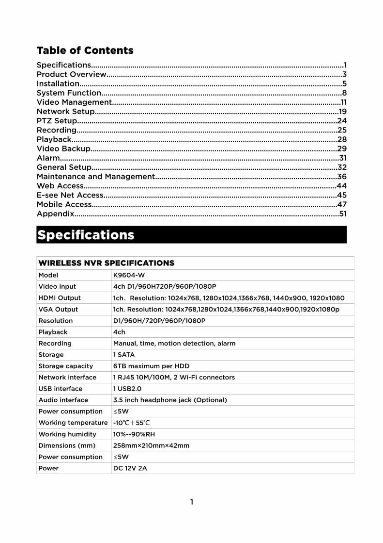
Table of ContentsSpecifications..........................................................................................................................1Product Overview..................................................................................................................3Installation...............................................................................................................................5System Function....................................................................................................................8Video Management...............................................................................................................11Network Setup......................................................................................................................19PTZ Setup..............................................................................................................................24Recording..............................................................................................................................25Playback................................................................................................................................28Video Backup.......................................................................................................................29Alarm.......................................................................................................................................31General Setup.......................................................................................................................32Maintenance and Management........................................................................................36Web Access..........................................................................................................................44E-see Net Access.................................................................................................................45Mobile Access.......................................................................................................................47Appendix................................................................................................................................51
Specifications
WIRELESS NVR SPECIFICATIONSModel K9604-W
Video input 4ch D1/960H720P/960P/1080P
HDMI Output 1ch,Resolution: 1024x768, 1280x1024,1366x768, 1440x900, 1920x1080
VGA Output 1ch. Resolution: 1024x768,1280x1024,1366x768,1440x900,1920x1080p
Resolution D1/960H/720P/960P/1080P
Playback 4ch
Recording Manual, time, motion detection, alarm
Storage 1 SATA
Storage capacity 6TB maximum per HDD
Network interface 1 RJ45 10M/100M, 2 Wi-Fi connectors
USB interface 1 USB2.0
Audio interface 3.5 inch headphone jack (Optional)
Power consumption ≤5W
Working temperature -10℃+55℃
Working humidity 10%--90%RH
Dimensions (mm) 258mm×210mm×42mm
Power consumption ≤5W
Power DC 12V 2A
1

WI-FI CAMERA SPECIFICATIONSTechnical Parameters Model PA3020-W
Sensor 1/3” Progressive Scan Sensor
Resolution 1920 x 1080 16:9 High Definition
Minimum illumination Color: 0.1 Lux; B/W: 0.01 Lux
Shutter 1/25s to 1/25,000s
Lens 4/6mm
OSD Date Time & Title
White Balance Auto
Day&Night IR cut filter with auto switch
3D-DNR Auto
Mirror/Flip On / Of
Smart stream Dual-stream: 1920x1080@15fps, 640x480@15fps
Signal / Noise rate > 39.1 Db
Interface RJ45 / WIFI 802.11b/g/n
General Specification Anti-thunder Level Standard IEC61000-4-5
Working Temperature / Humidity -10°C to + 50° / 30% to 80% RH
Power Input DC12V-1A
Power consumption ≤6W
Size 66*180mm
Weight 500g
Level of Protection IP66
Features・H.264, 4ch real-time D1, 1080P wireless NVR
・Built-in high-performance and high-stability wireless Wi-Fi routing module, supports 802.11bgn protocol, 150Mbps
・Can automatically access Wi-Fi network camera through the network cable
・Video preview / recording / playback / backup
・User-friendly (wireless simple matching, setup wizard, commonly used function menu, E-see net)
・Support ONVIF, N1 and IPC Access protocol
・Supported network service functions: P2P, DHCP, DDNS, PPPoE, E-Mail, FTP, etc.
・Support a variety of alarm triggering (video loss / motion detection, etc.) and alarm output (voice / E-Mail / FTP, etc.)
・Support Android / Apple mobile (or tablet) remote (LAN and Internet) access and control
2
・Support PC (client or browser) remote (LAN and Internet) access and control
・Support IPC configuration (coding control, image adjustment, OSD, etc.)
・Can match with IPC to support video motion detection
・Collaborate with IPC to support video masking
・Support user rights management
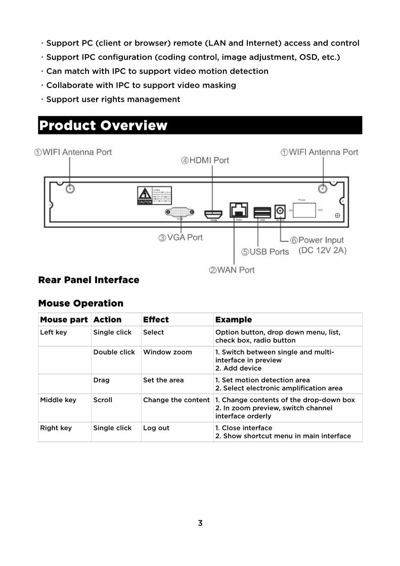
Product Overview
Rear Panel Interface
Mouse OperationMouse part Action Effect ExampleLeft key Single click Select Option button, drop down menu, list,
check box, radio button
Double click Window zoom 1. Switch between single and multi-interface in preview2. Add device
Drag Set the area 1. Set motion detection area2. Select electronic amplification area
Middle key Scroll Change the content 1. Change contents of the drop-down box2. In zoom preview, switch channel interface orderly
Right key Single click Log out 1. Close interface2. Show shortcut menu in main interface
3

Input methodName FunctionNumber 0~9
Character - / . _ * # @
Capital / lower case Toggle on/of caps
Backspace ←
InstallationNote: In order to extend the life of the machine, the device should be away from water, high-temperature and dusty environments and be placed in a well-ventilated area.Before use, ensure that the NVR is grounded correctly and the power supply can not exceed the power supply normal operating voltage range.
Pre-installation preparation・Determine the installation location of the NVRIt is recommended that the NVR be placed in the centre of the monitoring area,and the installation position of the IPC (wireless camera) and NVR should avoidobstacles as much as possible. When 4 multiple cameras are connected at the same time and there is no obstacle between the NVR and the IPC, the IPC should be placed in a spherical coverage area with a radius of 60m with NVR asa centre. The radius is reduced to 30 meters when there are one wall between the NVR and the IPC. When there are two walls, it is reduced to 15 meters radius (coverage is afected by the physical properties of the obstacles and the surrounding environment: as such, this information is for reference only.)
Connection steps・First, connect the NVR with the mouse and the display.
・Turn on the power of the NVR and the IPC, then connect the NVR to the IPC with the cable.
・Right click on the mouse -> click on adding camera-> delete all channels (Note: channels can be selected for deletion individually) -> code matching -> “start code matching?”
・Click Yes -> Show “on the code matching” -> NVR monitor screen shows that the code matching has been successful (Note: More than one camera can make code matching at the same time).
・If the code matching fails, click “Refresh” and try again after ensuring the network cable connections are good.
・Disconnect the network cable to see if the screen is normal: if so,that means the wireless camera has been added successfully -> when all the wireless camera added to the NVR means that the preparatory work is completed. (Figure 1 below)
4

Ensure correct operation・Connect the monitor, all IPCs and the antenna to the NVR and power them onto ensure they are functioning correctly. Once they are, you can install the kit.
Installation・Install the wireless cameras so that efective signal coverage is provided and connect 12V power supply.
・Power the wireless camera for 1 minute or so, you can see the video in the NVR monitor.
・If no image is shown, this indicates that the distance is too far.
The NVR antenna transmits a signal evenly. The IPCs should be parallel and at the same height for best results. The IPC antennae should be tangent with the range of transmission, as pictured above.
5
Correct Incorrect
System Function
StartupNOTE: Make sure that the power supply voltage matches the requirements of the NVR and that the NVR ground is well grounded.
・Malfunction or damage can occur following power interruption or improper voltage.
Before starting up, make sure that the display or monitor is connected to the video output of the device.
1. Connect the power supply: the front panel power indicator will turn red.
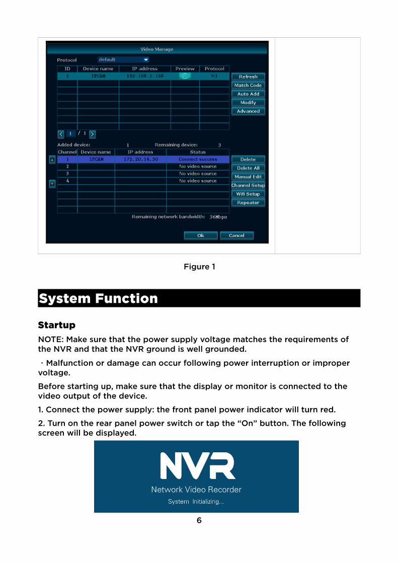
2. Turn on the rear panel power switch or tap the “On” button. The following screen will be displayed.
6
Figure 1
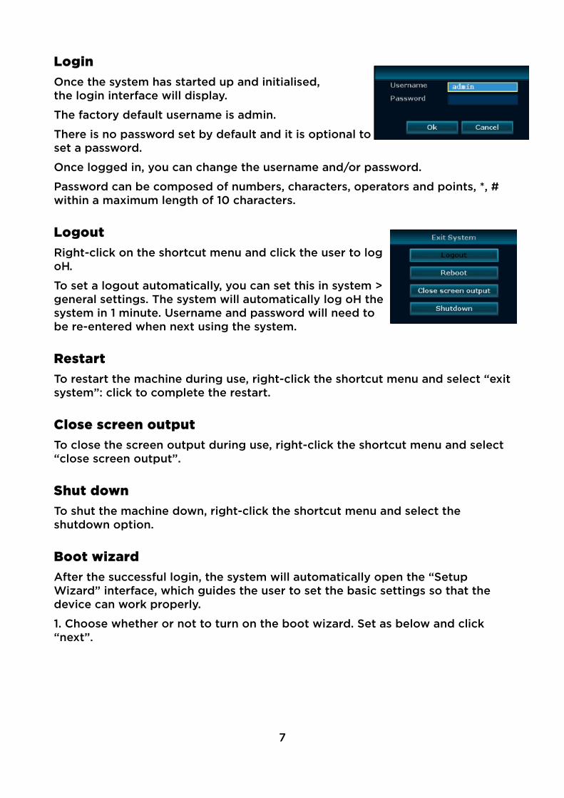
LoginOnce the system has started up and initialised,the login interface will display.
The factory default username is admin.
There is no password set by default and it is optional toset a password.
Once logged in, you can change the username and/or password.
Password can be composed of numbers, characters, operators and points, *, # within a maximum length of 10 characters.
LogoutRight-click on the shortcut menu and click the user to logof.
To set a logout automatically, you can set this in system >general settings. The system will automatically log of thesystem in 1 minute. Username and password will need tobe re-entered when next using the system.
RestartTo restart the machine during use, right-click the shortcut menu and select “exitsystem”: click to complete the restart.
Close screen outputTo close the screen output during use, right-click the shortcut menu and select “close screen output”.
Shut downTo shut the machine down, right-click the shortcut menu and select the shutdown option.
Boot wizard After the successful login, the system will automatically open the “Setup Wizard” interface, which guides the user to set the basic settings so that the device can work properly.
1. Choose whether or not to turn on the boot wizard. Set as below and click “next”.
7
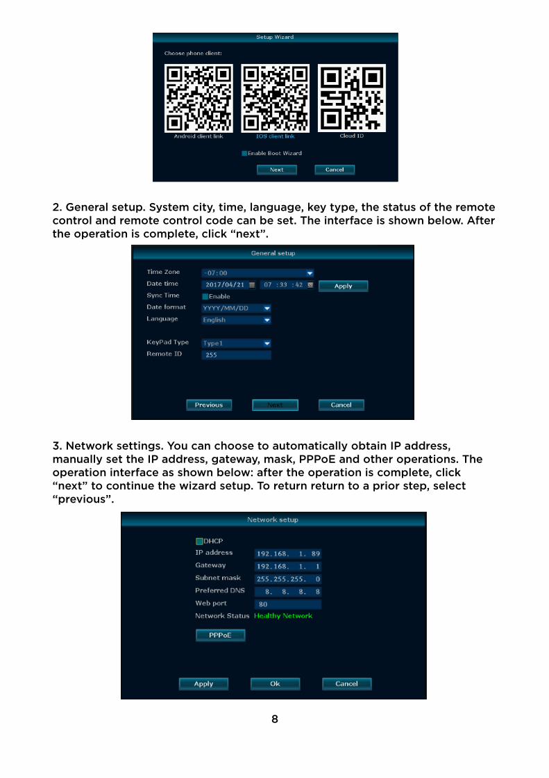
2. General setup. System city, time, language, key type, the status of the remotecontrol and remote control code can be set. The interface is shown below. Afterthe operation is complete, click “next”.
3. Network settings. You can choose to automatically obtain IP address, manually set the IP address, gateway, mask, PPPoE and other operations. The operation interface as shown below: after the operation is complete, click “next” to continue the wizard setup. To return return to a prior step, select “previous”.
8

4. Hard disk setup. Displays current list of hard disks, including the model, capacity, usage, status and format status. To format the hard disk, select the corresponding hard disk, then click the format button. Wait a moment, you can format the selected hard disk and the format status will display as “formatted”. The operation interface is shown below. After the completion of the operation, click Finish to complete setup. If you want to return to the previous step, select “cancel”. The changes will not take efect.
Video Management
Search for deviceUsed to search all IPC devices in the same network segment.
Steps: right-click the system main interface. In the pop-up menu, click the “camera adding” sub-menu > “video management” > video management interface, and click “refresh” button to complete the search IPC device operation The figure looks like this:
9

Add deviceCode matching: this function is mainly for matching the NVR with IPCs and sending NVR WiiFi account name and password to the IPC, so that IPC can automatically connect to the NVR. Ensure any bad channels are removed before carrying our this procedure.
Note: This is not necessary for the IPCs in the kit, only additional ones, should any be added later.
Method: first, connect the wireless camera to any LAN port of the NVR with thenetwork cable in the accessory box. Proceed to the main menu (right click the mouse) -> video management -> code match and select yes. Please wait for theresults. If it fails, the network cable has a poor connection: check and then click“Refresh”.
Fast adding: this function search all devices within the LAN and allocates IP addresses automatically.
Method: with NVR and IPC connected by network cable, right click in the main menu -> video management -> Fast adding.
Click search: the video management interface will show the information that the NVR normally communicated with IPC. Select fast adding: the system will automatically add the IPC which can work properly in idle channel and the monitor will display the IPC video signal. When working, the cable must not be unplugged. If the four channels are idle, the monitor will display IPC video signal when four cables are connected to the four IPCs after fast adding.
Note: After the fast adding, the camera and NVR must be connected through the network cable for the image to be displayed and cable transmission achieved.
Advanced setupsMulti-network segment search, repeated adding and smart adding are supported.
Right-click in the system main interface and select “Video Management” in the pop-up menu. In the open video management interface, click Advanced Setups,as shown below:
10
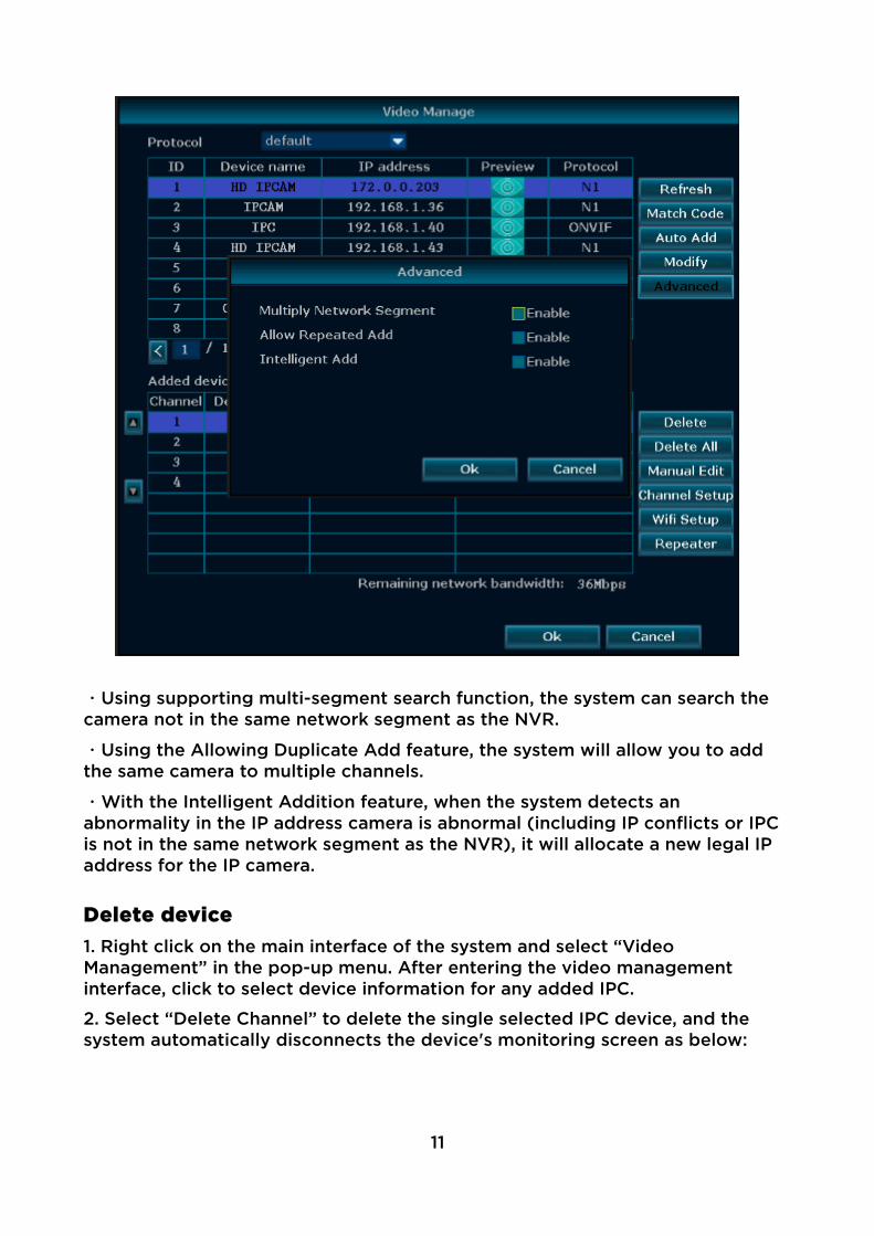
・Using supporting multi-segment search function, the system can search the camera not in the same network segment as the NVR.
・Using the Allowing Duplicate Add feature, the system will allow you to add the same camera to multiple channels.
・With the Intelligent Addition feature, when the system detects an abnormality in the IP address camera is abnormal (including IP conflicts or IPC is not in the same network segment as the NVR), it will allocate a new legal IP address for the IP camera.
Delete device1. Right click on the main interface of the system and select “Video Management” in the pop-up menu. After entering the video management interface, click to select device information for any added IPC.
2. Select “Delete Channel” to delete the single selected IPC device, and the system automatically disconnects the device's monitoring screen as below:
11

Click “delete all” button to delete all added IPC devices quickly.
Repeater setupIn the repeater setup page, first set up and connect any IPC to the NVR. This function increases the wireless transmission distance and extends the total range of wireless kit.
1. Right click on NVR’S GUI, left click “video management” > “repeater”.
12
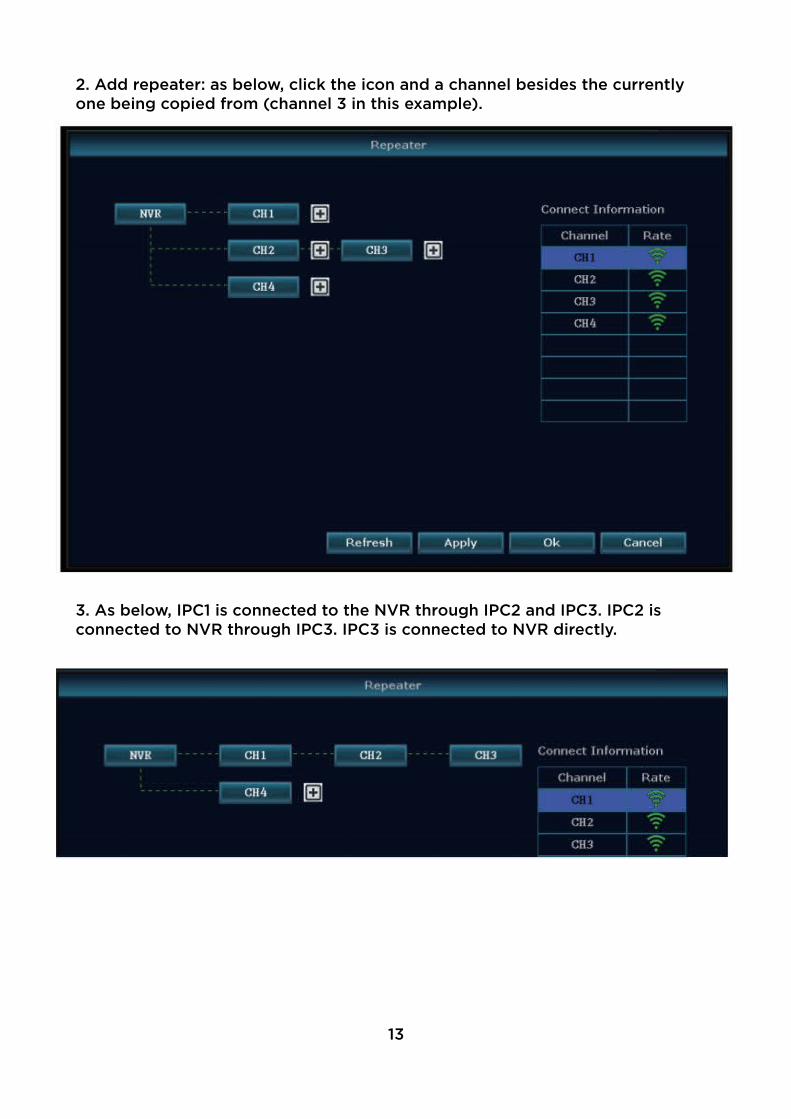
2. Add repeater: as below, click the icon and a channel besides the currently one being copied from (channel 3 in this example).
3. As below, IPC1 is connected to the NVR through IPC2 and IPC3. IPC2 is connected to NVR through IPC3. IPC3 is connected to NVR directly.
13
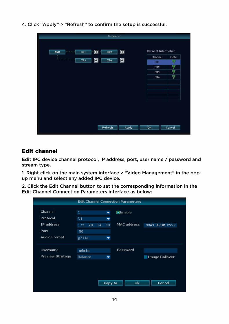
4. Click “Apply” > “Refresh” to confirm the setup is successful.
Edit channelEdit IPC device channel protocol, IP address, port, user name / password and stream type.
1. Right click on the main system interface > “Video Management” in the pop-up menu and select any added IPC device.
2. Click the Edit Channel button to set the corresponding information in the Edit Channel Connection Parameters interface as below:
14
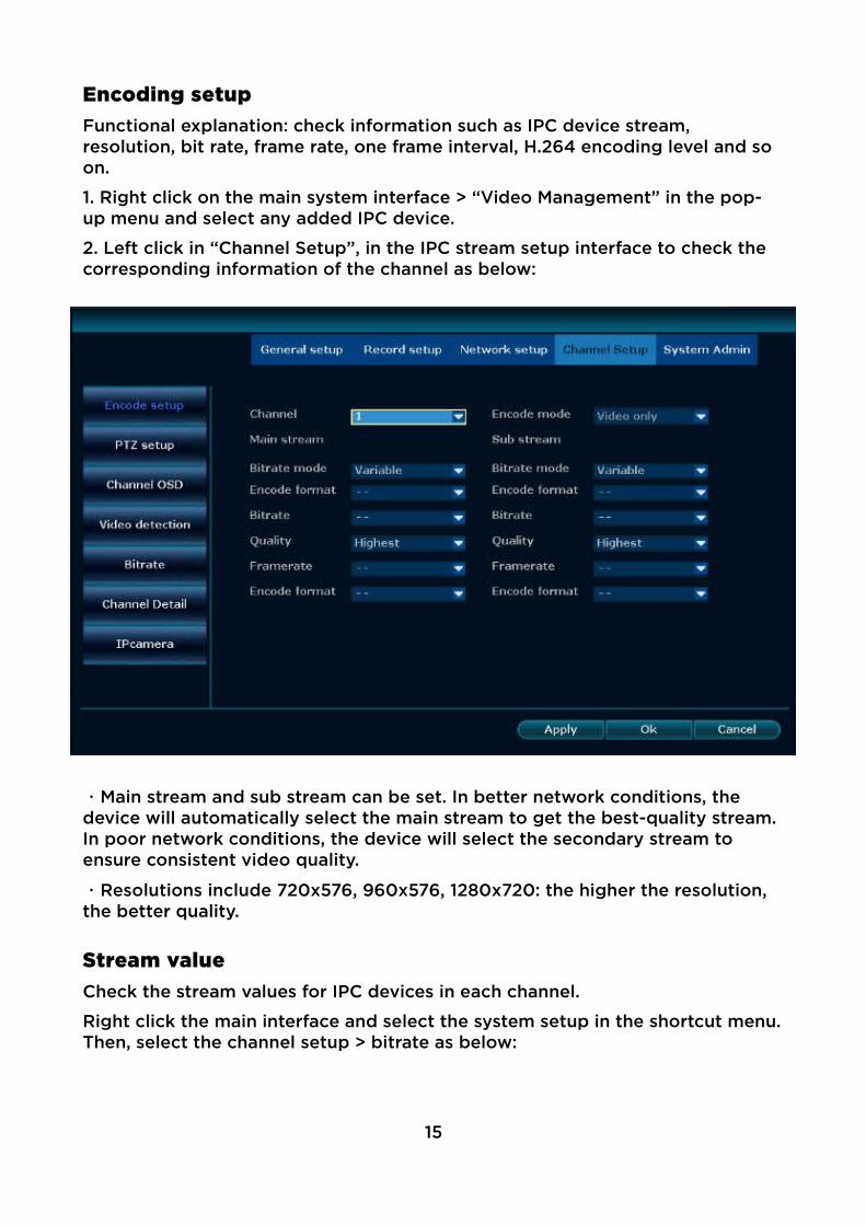
Encoding setupFunctional explanation: check information such as IPC device stream, resolution, bit rate, frame rate, one frame interval, H.264 encoding level and so on.
1. Right click on the main system interface > “Video Management” in the pop-up menu and select any added IPC device.
2. Left click in “Channel Setup”, in the IPC stream setup interface to check the corresponding information of the channel as below:
・Main stream and sub stream can be set. In better network conditions, the device will automatically select the main stream to get the best-quality stream. In poor network conditions, the device will select the secondary stream to ensure consistent video quality.
・Resolutions include 720x576, 960x576, 1280x720: the higher the resolution, the better quality.
Stream valueCheck the stream values for IPC devices in each channel.
Right click the main interface and select the system setup in the shortcut menu.Then, select the channel setup > bitrate as below:
15

Channel detailsView the camera details for each IPC device.
1. Right click the main interface and select the system setup in the shortcut menu. Select the channel setup > channel details as below:
2. Click refresh: you can search the camera in the current channel and check thedevice's channel name, resolution, stream value, video frame rate and software version details.
Channel OSDYou can adjust the colour of the IPC device in each channel, change the currently-displayed channel name, display status and communication quality. Icons displaying the communication situation are shown in the main multi-screen interface. Display setup can adjust the specific location of the icon.
16

1. Right click the main interface and select the system setup in the shortcut menu. Select the channel setup > channel OSD as below:
2. Select colour adjustment to enter the colour adjustment interface. Chroma, brightness, saturation, contrast, and bright / soft picture settings can be adjusted.
3. Select the display setup to enter communication icon adjustment. Position and magnification are adjustable.
Camera setup1. Right click the main interface and select the system setup in the shortcut menu. Select the channel setup > channel OSD as below:
17

2. Select the corresponding channel. In installation mode, wall, hanging and desktop can be selected.
・Installation mode can be selected only when the panorama camera is connected.
・Only panoramic cameras with the N1 protocol are supported.
Network Setup
Network setupNote: if the device is used for network monitoring, the network must be set up for normal use. Factory default IP address: 192.168.1.114.
1. Right click the main interface and select the system setup in the shortcut menu. Select “Network setup”. The basic setup is shown below:
2. Set the network parameters. In the network setup, the device's IP address, subnet mask, gateway and other information can be modified. Automatic access to IP can be checked. E-see net (P2P) and E-see net ID for remote monitoring can be enabled.
3. After setup, click the “Apply” button to save the setup, or click the “OK” button to save the setup and exit the settings interface.
Function name Function description NotesIP address Used to set the IP address of the
device manually.“Automatically get IP” must be unchecked
E-see net (P2P) When this function is checked, the IDnumber used for remote monitoring is displayed.
18

Subnet mask Set the subnet mask for this device.
Gateway Set the gateway address of the device.
Physical address Set the hardware address of the device.
Cannot be the address as the physical LAN address.
Web port Used to send video and other controlsignals, the default is 80.
Web pages, PC clients and mobile phones all use this port.
Automatically get IP When this function is checked, the IPaddress of the device will be acquired automatically. Otherwise, it must be set manually.
When using the DHCP function, you can not manually modify parameters such as IP.
Network diagnostic information
Enables network diagnostics function.
Support for diagnostic types include network card exception, network parameter configuration exception, IPC connection error diagnosis.
Network status Displays the current network status. If the ID number is not online, it can be operated according to thenotifying information.
DDNSIf the device does not have a fixed access address, using DDNS (dynamic domain name resolution) to access the device through the domain name, issuescaused by dynamic IPs can be resolved for simple device access.
1. Right click the main interface and select the system setup in the shortcut menu. Select network setup > dynamic domain name as below:
2. Check to turn on the DDNS Function check box.
3. Fill in the domain name, user name and password information.
4. Click the “Apply” button to save the setup.
19

・Currently-supported providers are 3322, changeip, no-ip, dyndns and oray.
・If the check box is unchecked, the dynamic domain name information will notbe edited.
FTPFor alarm and video test results uploading.
1. Right click the main interface and select the system settings in the shortcut menu. Select the network setup > FTP as below:
2. Check the FTP function to open the check box.
3. Fill in the FTP host, port, user name and password and other information.
4. Set the time period, click the “test” button. After the test is successful, click the “Apply” button to save the setup.
EmailFor user email alert of alarm and video test results
1. Right click the main interface and select the system settings in the shortcut menu. Select the network setup > E-Mail as below:
20

1. Check the E-Mail function to open the check box.
2. Fill in the SMTP server, port, user name, sender, recipient and other information.
3. Click the “test” button. After the test is successful, click “Apply” to save the setup.
Detailed function list:
Function name Function descriptionSMTP server Input format is smtp.[Mailbox server name].com, e.g.: smtp.126.com
User name Mailbox full user name, e.g.: [email protected]
Password Email Password
Encryption type The default can choose to not select, if the test fails, then modify to SSL
Sender The sender's full email address, need to be consistent with the user name,e.g.: [email protected]
Recipient The recipient's full email address can be used to receive mail from the sender's address
Interval The time interval for receiving mail
Health mail interval The time interval for sending messages when the device is running normally
PPPoESupport dial-up Internet access.
1. Right click the main interface and select the system settings in the shortcut menu. Select the network setup > PPPoE as below:
21
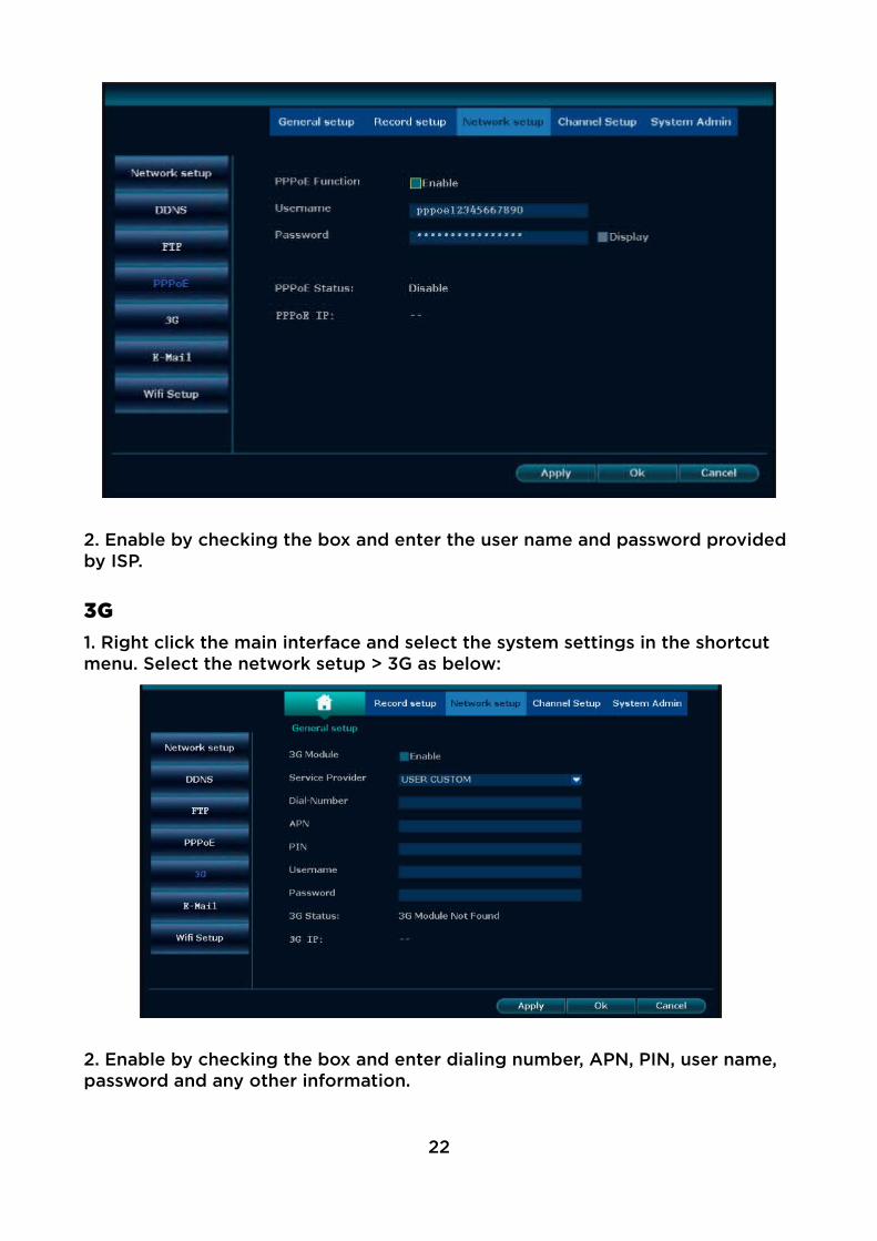
2. Enable by checking the box and enter the user name and password provided by ISP.
3G1. Right click the main interface and select the system settings in the shortcut menu. Select the network setup > 3G as below:
2. Enable by checking the box and enter dialing number, APN, PIN, user name, password and any other information.
22
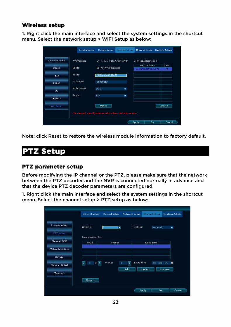
Wireless setup1. Right click the main interface and select the system settings in the shortcut menu. Select the network setup > WiFi Setup as below:
Note: click Reset to restore the wireless module information to factory default.
PTZ Setup
PTZ parameter setupBefore modifying the IP channel or the PTZ, please make sure that the network between the PTZ decoder and the NVR is connected normally in advance and that the device PTZ decoder parameters are configured.
1. Right click the main interface and select the system settings in the shortcut menu. Select the channel setup > PTZ setup as below:
23

Parameter Function descriptionChannel Select the target channel.
Protocol The selection must be consistent with the PTZ protocol.
Device address Enter the address of the specified decoder.
Band rate Select the band rate matching the connected PTZ.
Copy to Enables you to select a target video channel and apply the current channel setup information to this channel.
PTZ control operations1. In the main interface, double-click the interface needing to be set.
2. Right-click in the preview interface andselect PTZ control in the shortcut menu, asshown in the figure to the right:
Operation:
・Arrow keys control the vertical and horizontal movement of the camera.
・The A icon enables automatic circular motion
・+ and – adjust the zoom focal length and aperture.
PTZ automatic cruise setup operationsOperation:
1. Right click the main interface and select the system settings in the shortcut menu. Select the channel setup > PTZ setup.
2, Click on the right side of the preset “?” button to enter the control interface and set the preset point.
3, Select the preset position and set the direction.
4, Right-click to return to the setup interface, set to hold time.
5, Click the New button to complete a preset point of the setup.
6, Repeat the above steps 2-5 by setting the other preset points.
7, After setup, check the cruise and start checking box and change the pan / tiltspeed as needed as below:
8, Right click to return to the setup interface and click the Apply button to savethe setup.
24

・Preset position is the cruise point of the cruise route: the path moves from small to large according to cruise point.・Hold time is the time the dome camera stays at this preset point.・Cruising speed is the rotating speed of the dome camera from one to anotherpoint.
Recording
Manual recordingWith the manual recording function, the user can quickly turn the video on or of.
1. Right click the main interface and select the system settings in the shortcut menu. Select the channel setup > PTZ setup.
2. Select the channel for recording:
3. To enable manual recording for allchannels, click the “All on” button.
4. To turn of manual recording for all channels, click the “All of” button.
5. After selecting, click “OK” to complete the manual recording configuration.
・Recording priority: Alarm recording> Mobile recording> Manual recording> Timed recording
Timed recordingWith the manual recording function, the system will record automatically in the set period.
1. Right click on the main interface, select and click System Setup in the shortcut menu.
2. Click “Record setup” and click to select the recording plan as below:
25
3. Use the drop-down box to select the channel and week for timed recording.
4. To set the time period for the scheduled recording, check the “Time” box.
5. If the other channels are the same as the channel recording schedule setup, you can click click “Copy to” and select any or all of the other channels to apply the setup details quickly.
6. Click the “Apply” button to save the setup.
・Timed recording can be set across up to four time periods. For 24-hour recording, the time period 1 would simply be set from 0:00 to 24:00 o’clock. The time period(s) set by the user will be displayed in the colour bar.
Motion detection recordingThe system will record when detecting the movement.
1. Right click on the main interface, select and click System Setup in the shortcut menu.
2. On the System Setup screen, click Video Setup and select the recording schedule.
3. Select the channel and the week.
4. Check the motion checking box.
5. Set the motion detection area and sensitivity, the specific steps are as follows:
・In the Channel Setup interface, select and click “Video Detection”.
・Select the channel you want to set and sensitivity.
・For detection type, select “Motion”.
・Click the “Apply” button to save the setup.
Note: If you need to set motion detection for other channels, repeat the above steps. The default sensitivity for video detection is “higher”.
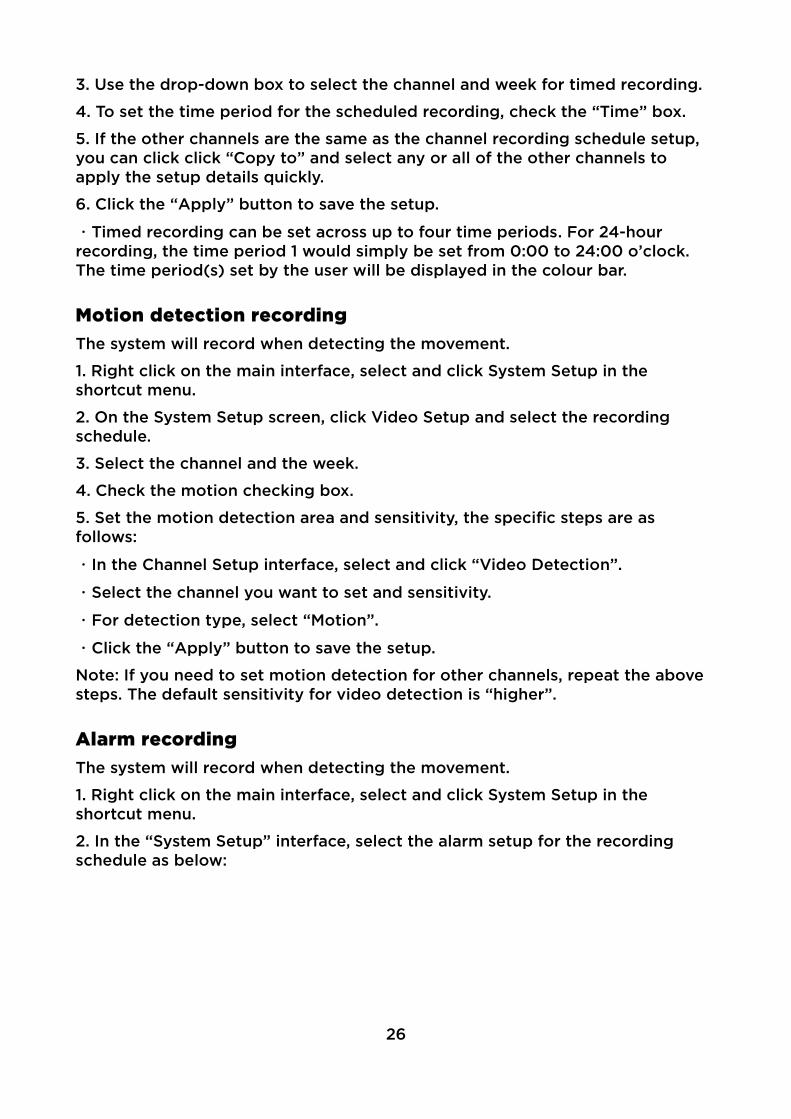
Alarm recordingThe system will record when detecting the movement.
1. Right click on the main interface, select and click System Setup in the shortcut menu.
2. In the “System Setup” interface, select the alarm setup for the recording schedule as below:
26
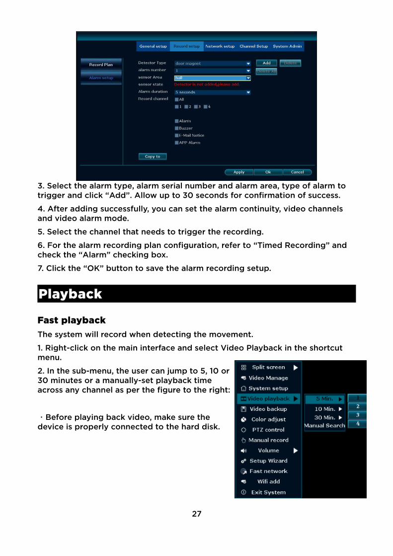
3. Select the alarm type, alarm serial number and alarm area, type of alarm to trigger and click “Add”. Allow up to 30 seconds for confirmation of success.
4. After adding successfully, you can set the alarm continuity, video channels and video alarm mode.
5. Select the channel that needs to trigger the recording.
6. For the alarm recording plan configuration, refer to “Timed Recording” and check the “Alarm” checking box.
7. Click the “OK” button to save the alarm recording setup.
Playback
Fast playbackThe system will record when detecting the movement.
1. Right-click on the main interface and select Video Playback in the shortcut menu.
2. In the sub-menu, the user can jump to 5, 10 or30 minutes or a manually-set playback timeacross any channel as per the figure to the right:
・Before playing back video, make sure thedevice is properly connected to the hard disk.
27
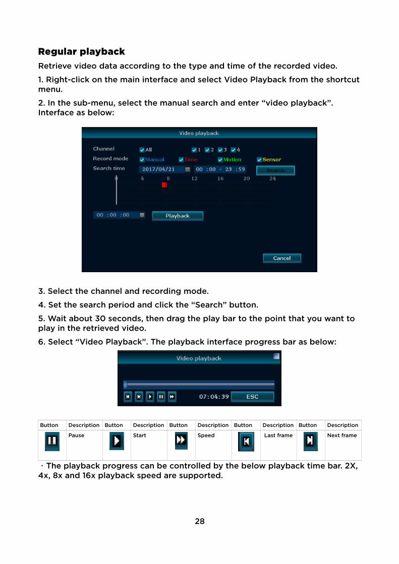
Regular playbackRetrieve video data according to the type and time of the recorded video.
1. Right-click on the main interface and select Video Playback from the shortcutmenu.
2. In the sub-menu, select the manual search and enter “video playback”. Interface as below:
3. Select the channel and recording mode.
4. Set the search period and click the “Search” button.
5. Wait about 30 seconds, then drag the play bar to the point that you want to play in the retrieved video.
6. Select “Video Playback”. The playback interface progress bar as below:
Button Description Button Description Button Description Button Description Button Description
Pause Start Speed Last frame Next frame
・The playback progress can be controlled by the below playback time bar. 2X, 4x, 8x and 16x playback speed are supported.
28
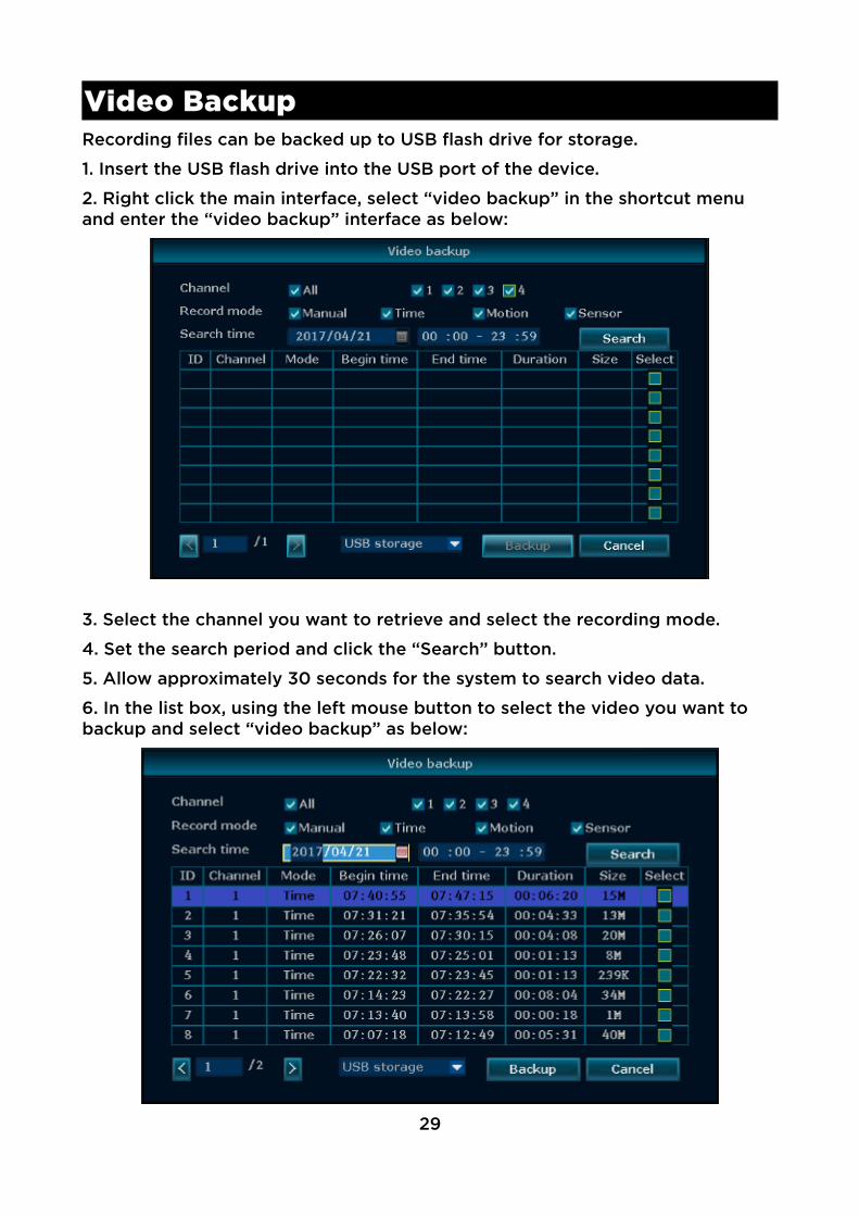
Video BackupRecording files can be backed up to USB flash drive for storage.
1. Insert the USB flash drive into the USB port of the device.
2. Right click the main interface, select “video backup” in the shortcut menu and enter the “video backup” interface as below:
3. Select the channel you want to retrieve and select the recording mode.
4. Set the search period and click the “Search” button.
5. Allow approximately 30 seconds for the system to search video data.
6. In the list box, using the left mouse button to select the video you want to backup and select “video backup” as below:
29
・After the search is complete, the user can see the start time, end time, duration and storage size of the video data.
・To ensure successful video backup, make sure the USB flash disk has enough storage space.
Alarm
Motion detection alarmWhen an object is detected in the selected screen, the device will trigger an alarm and output an alarm.
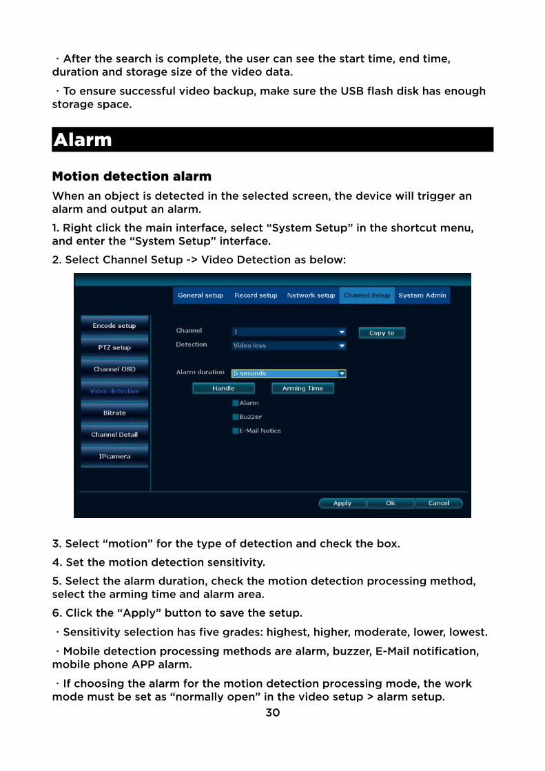
1. Right click the main interface, select “System Setup” in the shortcut menu, and enter the “System Setup” interface.
2. Select Channel Setup -> Video Detection as below:
3. Select “motion” for the type of detection and check the box.
4. Set the motion detection sensitivity.
5. Select the alarm duration, check the motion detection processing method, select the arming time and alarm area.
6. Click the “Apply” button to save the setup.
・Sensitivity selection has five grades: highest, higher, moderate, lower, lowest.
・Mobile detection processing methods are alarm, buzzer, E-Mail notification, mobile phone APP alarm.
・If choosing the alarm for the motion detection processing mode, the work mode must be set as “normally open” in the video setup > alarm setup.
30

・With the mobile phone APP alarm, you can send motion detection alarm information to the phone E-see net cloud client.
Video loss alarmIf a channel's video signal is lost, you will be notified in real time.
1. Right click the main interface, select “System Setup” in the shortcut menu and enter the “System Setup” interface.
2. Select Channel Setup > Video Detection.
3. Select “Video Loss” under Detection as below:
4. Set the alarm duration period, check the motion detection processing methods and arming time.
5. Click the “Apply” button to save the setup.
・If the other channel setup are the same as the channel, select the channel andclick “Copy to”.
General Setup
General setupCreate setups for frequently used functions.
1. Right click the main interface and select “System Setup” in the shortcut menu.
2. Select General Setup > General Setup as below:
31

The operation is explained in the table below:
Function DescriptionAutomatic logout Select whether the system is automatically logged of without operation.
Button sound Select whether to turn on the button sounds on the control panel.
Language selection Select the language.
Remote control switch
Select whether to allow remote control use.
Boot wizard Select whether to enable the wizard when starting up.
Show the e-see net ID when previewing
Select whether to display the E-see net ID and online status in the preview interface.
Time setupSet the system time zone, date, time and daylight saving time.
1. Right click the main interface, select the system setup > General Setup > timesetup as below:
32
Screen setupThe following screen parameters can be set:
Function DescriptionMonitor adjustment Set hue, brightness, saturation, and contrast.
OSD transparency Modify the transparency of the interface.
VGA Resolution Select the screen resolution.
Automatic cruise Whether to open the camera movement and set the time.
1. Right click the main interface, select system setup > General Setup > screen setup.
・Skip Video Loss means that no image will appear on the screen if the screen is not displayed when cruising.
・Screen numbers correspond to the automatic cruising setting.
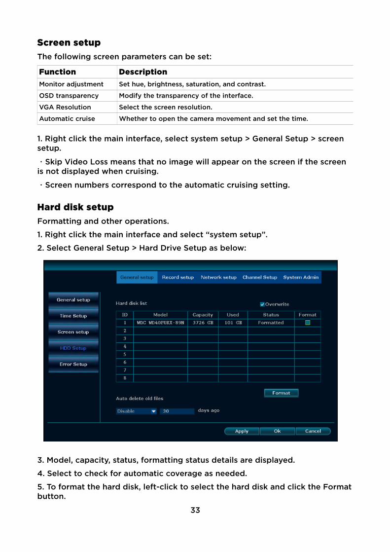
Hard disk setupFormatting and other operations.
1. Right click the main interface and select “system setup”.
2. Select General Setup > Hard Drive Setup as below:
3. Model, capacity, status, formatting status details are displayed.
4. Select to check for automatic coverage as needed.
5. To format the hard disk, left-click to select the hard disk and click the Formatbutton.
33

6. To delete the old file automatically, select “User-defined” in the drop-down box and fill in the number of days.
7. Click the “Apply” button to save the setup.
・Check the automatic coverage means that the hard disk will automatically overwrite the oldest video data when the capactiy is filled.
・Clicking the format button will display a message “all data will lost after formatting the hard disk”. Click “OK” button to start formatting.
・Files can be selected to be automatically deleted, up to a maximum of 255 days, or the option can be disabled.
Exception setupAlarm mode for the system's exception type can be set.
1. Right click the main interface, select and click “system setup”.
2. Select the General Setup > hard disk setup as below:
3. Select the exception type, click “Open” and select the alarm mode.
4. Click “Apply” to save the setup.
34

Maintenance and Management
System messageThe user can check the device name, device model, device serial number, hardware version, software version, build time and other information.
1. Right click the main interface, select the system setup in the shortcut menu, and then select the system management -> version information as below:
・When seeking assistance or troubleshooting, ensure the version information is provided.
Hard disk informationThe user can check all the hard disk models installed and their capacity, usage, status, total capacity, total consumption and other information.
1. Right click the main interface, select the system setup in the shortcut menu, then select the system management > hard disk information as below:
35

Log informationCorresponding log information according to the time type, start time and end time can be seen as below:
36

1. Right click the main interface, select the system setup in the shortcut menu, and then select the system management > log information.
2. Select the time type in the drop-down menu.
3. Set the start time and end time and search: the corresponding log information will be displayed.
・Click on the next page to read the log.
・Logs are stored on the hard disk: information will be lost if the disk is formatted.
・Times for the following events are available: system start-up, system shutdown, system configuration revision, video, alarm, device warning and all.
User management・The default administrator name is admin and the password is empty.
・Administrators can add, remove, and edit user rights.
Adding user
1. Right click the main interface, in the shortcut menu, select the system setup, and then select the system management -> user management.
2. Click “New User” to enter the following interface:
3. Enter the new user name and password.
37
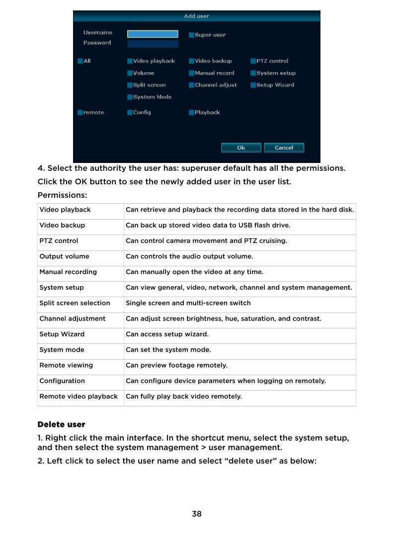
4. Select the authority the user has: superuser default has all the permissions.
Click the OK button to see the newly added user in the user list.
Permissions:
Video playback Can retrieve and playback the recording data stored in the hard disk.
Video backup Can back up stored video data to USB flash drive.
PTZ control Can control camera movement and PTZ cruising.
Output volume Can controls the audio output volume.
Manual recording Can manually open the video at any time.
System setup Can view general, video, network, channel and system management.
Split screen selection Single screen and multi-screen switch
Channel adjustment Can adjust screen brightness, hue, saturation, and contrast.
Setup Wizard Can access setup wizard.
System mode Can set the system mode.
Remote viewing Can preview footage remotely.
Configuration Can configure device parameters when logging on remotely.
Remote video playback Can fully play back video remotely.
Delete user
1. Right click the main interface. In the shortcut menu, select the system setup, and then select the system management > user management.
2. Left click to select the user name and select “delete user” as below:
38

3. Click “OK” at the confirmation prompt: the user will be deleted.
・Superusers cannot be deleted.
Edit user
1. Right click the main interface. In the shortcut menu, select the system setup, and then select the system management > user management.
2. Left click to select the user name and select “Edit user”. You will be taken to the “Edit user” interface as below:
3. Re-edit the user's permissions and click “OK” to save.
・Superusers cannot be edited.39
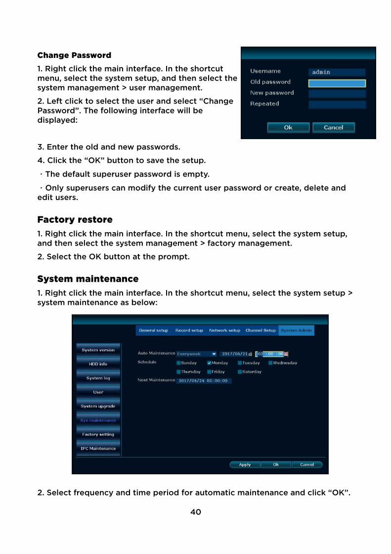
Change Password
1. Right click the main interface. In the shortcutmenu, select the system setup, and then select thesystem management > user management.
2. Left click to select the user and select “ChangePassword”. The following interface will bedisplayed:
3. Enter the old and new passwords.
4. Click the “OK” button to save the setup.
・The default superuser password is empty.
・Only superusers can modify the current user password or create, delete and edit users.
Factory restore1. Right click the main interface. In the shortcut menu, select the system setup, and then select the system management > factory management.
2. Select the OK button at the prompt.
System maintenance1. Right click the main interface. In the shortcut menu, select the system setup >system maintenance as below:
2. Select frequency and time period for automatic maintenance and click “OK”.
40

Software upgradeFor user-end firmware updates.
Method 1
1. Right click the main interface. In the shortcut menu, select the system setup >software upgrade as below:
2. Place the firmware file on the root directory of a USB flash drive and insert itinto the USB port.
3. Select the USB storage device > System > Start.
4. The progress of the update is displayed on the bar. Once complete, the device will restart automatically.
Method 2
Note: This procedure should only be carried out with a good network speed.
1. Right click the main interface, in the shortcut menu, select the system setup, and then select the system management -> software upgrades.
2. Find online upgrade, check the “automatically upgrade after downloading”, and click to begin.
3. The progress of the update is displayed on the bar. Once complete, the device will restart automatically.
・Ensure an upgrade file is placed in the root directory of the USB drive.
・Do not power of when upgrading, otherwise it can permanently damage the unit.
・When upgrading online, please ensure that the device is successfully connected.
・The server address, port and network path can be set for an online update.
41

IPC maintenanceFor firmware updates for the IPCs.
1. Right click the main interface, in the shortcut menu, select the system setup, and then select the system management -> IPC maintenance as below:
Click to refresh, you can search the current camera in the LAN. The searchable camera will show the current channel it in, the IP address port, and the current software version.
2. Place the firmware file on the root directory of a USB flash drive and insert itinto the USB port.
3. The progress of the update is displayed on the bar. Once complete, the device will restart automatically.
・Only IPCs with specific protocol can update firmware. If you can not search for upgrades, it means this camera does not support this feature.
Web Access
This product features an embedded web server, support remote web access. Once the device is connected to the network, the user can access the device remotely through a browser by entering an IP address.
Various browsers are supported, including IE, Chrome and Firefox.42

Login1. Enter the device's IP in a browser address bar, e.g. http://192.1.1.28
2. Enter the username and password.
3. Click “Login” to access the preview interface as below:
4. The first time you will be prompted to download and run WebClient.exe control as below:
5. Log in again to preview the interface normally.
・IP address can be checked in the system setup > network setup.
・Multiple users can log in through multiple PCs simultaneously.
・If the web page port number is modified (default is 80), when input IP address in the browser, you need to enter the port number after the address, such as 192.168.1.28:80.
・If you can not load the software for the first time, you need to set Active X controls and plugins enabled in: Tools > Internet Options > Security > User defined level.
PreviewIn the preview interface (above), controls are available to configure, mute, control PTZ and list all channels.
・The screen can display 1, 4, 9, 16, 25 or 36 video feeds simulteously.
・Main and sub-stream view is also available.
43

Playback
1. Click the playback icon in the preview interface:
Configuration
1. Click the configuration icon in the preview interface:
2. Enter the configuration interface as below:
・A non-superuser must have remote configuration rights. You can view and assign the user to remote configuration rights in System Management -> User Management -> Edit User.
E-see Net Access
E-see net login1. Navigate to http://www.dvr163.com in a browser. The interface will be shown as below:
44

2. Under “Cloud ID login”, enter the username and password.
3. Click “Login” to access the preview interface as below:
・Device ID can be set in system setup > network setup. Check the e-see net(P2P) check box to obtain.
・The E-see net ID must be online to enable remote login.
Username loginUsername login enables management of multiple devices.
1. Navigate to http://www.dvr163.com in a browser.
2. Under “Username login”, enter the username and password.
3. Click “Login” and follow the prompts to register.
・Support English and Chinese language.
Mobile Access1. Software download.
Method 1: Log in to the website www.dvr163.com, click “support and download”> “software download” > “mobile client software” and download to the computer, then copy to the phone to install.
Method 2: Either use your phone to scan the QR code on the above website or navigate to the following website:
Android: http://www.dvr163.com/download/android.php
iOS: https://itunes.apple.com/au/app/eseecloud/id1032277907?mt=8
45

2. Open the app, interface shown right:
Note: After the initial installation, the login pagewill be displayed. You will need to register anaccount first. After the account login, every timeyou open the software, the app will open to deviceinterface. Follow the prompts to fill in the username and password information, enter the mailbox(optional, for password recovery), you can alsoclick “local” to enter the mobile client to addequipment.
By selecting “local”, the login screen will bedisplayed each time the app is opened.
After logging in to the user account, the deviceinformation will be saved on the server. When youlog in to the account in another phone, the devicewill be displayed automatically. You can choose torestrict access to the one mobile device.
3. To add a device, click the + in the top rightcorner, select cloud ID login and fill in the NVRconnection information as below:
・Options available to add device are cloud ID, IP / DDNS and LAN scan.
・Once logged in to Cloud ID, the system will automatically identify the ID number.
・In LAN scan, you will need to choose the correct channel number (the defaultis 4).
4. Click on the added device to preview the feed. The default is 4 channels: youcan choose a particular channel to preview as below:
46

・Up to 16 channels can be previewed at the same time
・4, 6, 8, 9, 13 or 16 channels are viewable simultaneously by split screen.
・If PTZ is supported, the PTZ button can control the IPC.
5. Remote playback is available through the preview interface as below:
47
・Remote playback can specify playback time and channel.
・Only 1-channel playback is supported.
・Sound is supported if the recording includes it.
・Recordings can be saved to the mobile device in HD (main stream) or SD (sub stream) by tapping on the playback.
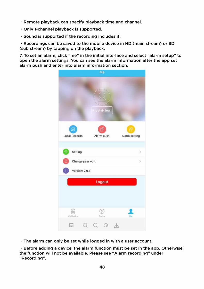
7. To set an alarm, click “me” in the initial interface and select “alarm setup” to open the alarm settings. You can see the alarm information after the app set alarm push and enter into alarm information section.
・The alarm can only be set while logged in with a user account.
・Before adding a device, the alarm function must be set in the app. Otherwise,the function will not be available. Please see “Alarm recording” under “Recording”.
48

Appendix
Hard disk capacity conversionDevice Capacity Operating system available
B 1 B = 8 b B 1 B = 8 b
MB 1 MB = 1000KB
MB 1 MB = 1024 KB
GB 1 GB = 1000MB
GB 1 GB = 1024 MB
TB 1 TB = 1000GB
TB 1 TB = 1024 GB
・This table uses the standard hard drive manufacturer measurement of 1GB as 1000MB.
Video required capacity calculation1. Single channel image per hour video file size: A=B÷8÷1000×3600
2. N-channel images daily (24 hours) video file size: A=B÷8÷1000×3600×24×N
3. N-channel image recording D-day file size: A=B÷8÷1000×3600×24×D×N
・A is the required hard disk capacity, B is the bit rate size, N is the number of video channels, D is the number of recording days.
User manual is subject to change without notice. For the latest version of your user manual, please visit https://www.kogan.com/usermanuals/
49