table of contents e-manuals/ac pro/thumb drive fi… · utility relay company p a g e 1 the...
TRANSCRIPT

URC Utility Relay Company
ac-pro-MP™
i-ac-pro-MP masterpact mp direct replacement trip unit
instruction manualPlug-in Replacement Trip Unit for Masterpact MP
Type STR-18M, 28D, 38S or 58U
C h a g r i n F a l l s , O H 4 4 0 2 3 P h o n e : 8 8 8 . 2 8 9 . 2 8 6 4 w w w . u t i l i t y r e l a y . c o m

AC-PRO-MPTM
Instruction Manual www.utilityrelay.com
Manual Rev 0
Section: Page
1.0 Introduction ........................................................ 1 2.0 Qualification Tests ............................................. 1 3.0 General ............................................................. 2 3.1 Front View ................................................ 2 3.2 Rear View ................................................ 3 3.3 Top View .................................................. 3 4.0 Installing the AC-PRO-MP
TM .............................. 4
4.1 Remove Front Cover ................................ 4 4.2 Disconnect STR Wiring ............................ 4 4.3 Remove STR Trip Unit ............................. 5 4.4 Connect CT Connectors .......................... 5 4.5 Attach AC-PRO-MP
TM to Breaker ............ 5
4.6 Check Alignment of “Push-to-Reset” Rod ................................ 6 4.7 Remove Auxiliary Terminal Blocks ........... 6 4.8 Connect Auxiliary Terminal Blocks to AC-PRO-MP
TM Auxiliary Wiring
Connector ................................................ 6 4.9 Plug Auxiliary Wiring Connector into AC-PRO-MP
TM ......................................... 6
4.10 Modify & Install Terminal Block Cover .... 7 4.11 Replace Breaker Front Cover ................. 7 5.0 Entering or Changing Settings ........................... 7 5.1 Using the Front Panel .............................. 7 5.2 Using the USB Interface .......................... 11 6.0 Quick-Trip
TM Arc Flash Reduction ...................... 12
6.1 Local Quick-TripTM
Switch ........................ 12 6.2 Optional Remote Quick-Trip
TM Switch ...... 13
7.0 Retrieving Last Trip Data ................................... 13 8.0 Replacing the Battery ......................................... 14 9.0 Self-Test Feature ............................................... 15
10.0 Primary & Secondary Injection Testing .............. 15 10.1 Primary Injection Testing ............................ 15 10.2 Secondary Injection Testing ....................... 15
11.0 Warranty ............................................................ 15 12.0 Environmental Ratings ....................................... 15
Time-Current-Curves: Page
13.1 AC-PROTM
STR-18M TCC .............................. 16 13.2 AC-PRO
TM STR-28D TCC .............................. 17
13.3 AC-PROTM
STR-38S TCC .............................. 18 13.4 AC-PRO
TM STR-58U TCC .............................. 19
13.5 AC-PROTM
STR-38S & 58U GF TCC ............. 20 13.6 AC-PRO
TM STR-58U Load Monitoring TCC .... 21
13.7 AC-PROTM
Quick-TripTM
Inst. TCC ................. 22 13.8 AC-PRO
TM Quick-Trip
TM GF TCC ................... 23
Firmware Revision: H1.0F1.0

Utility Relay Company
P a g e 1
The AC-PRO-MP
TM is a plug-in, direct replacement trip
unit for the STR trip units on the Merlin Gerin & Square D Masterpact MP breakers. The AC-PRO-MP
TM offers the following features:
o User programmed to replace any of the versions of
STR-18M, 28D, 38S or 58U trip units on IEC or UL rated Masterpact MP breakers.
o A security code system protects against unauthorized
changes to the settings. o Includes the exact trip unit functions, settings and time-
current-curves as the original STR trip unit.
o Includes the same information and alarm features as the original STR trip unit.
o Includes additional self-test features.
o No physical rating plug is required. The required rating plug value is a programmed setting.
o Includes the Quick-TripTM
arc flash reduction settings with an On/Off switch and LED on the front of the trip unit as a standard feature.
o An optional remote Quick-TripTM
On/Off switch and indicating light can also be connected.
o Easy access to the settings and last trip data is provided
with an OLED graphic display and “smart” push buttons.
o The OLED display is easy to read in either low or high ambient light conditions.
o A USB port on the front of the trip unit provides for connection to a laptop computer for easy access to the settings and last trip data.
o A test port for connection to a secondary injection test set that performs actual Phase and Ground Fault tests not simulated tests.
Zone Select Interlocking (ZSI) and communications are not currently available.
The AC-PRO-MPTM
was tested by an independent laboratory and found in compliance with the following standards: o ANSI/IEEE C37.90.2-2004, RF Susceptibility o ANSI/IEEE C37.90.1-2002, Surge Withstand
o EN61000-4-2 Electro-Static Discharge
1.0 Introduction 2.0 Qualification Tests

AC-PRO-MPTM
Instruction Manual www.utilityrelay.com
P a g e 2
3.1 Front View of AC-PRO-MP
TM
A. Pop-out tripped indicator
This indicator is mechanically interlocked to the breaker mechanism and pops out when the breaker is tripped by the trip unit.
After a trip, the pop-out indicator must be pushed to the flush position before the breaker can be closed.
B. Battery Cover
To replace the battery, remove the four (4) 2-56 screws and battery cover, remove the old battery and insert a new CR-P2, 6 Volt Lithium battery. Replace the battery cover and screws. See Section 8.0.
C. OLED Display
The display is normally off. Pushing the DISPLAY button (E) turns on the display.
D. “Smart” Push Buttons
These push buttons perform the functions indicated on the bottom of the OLED display.
E. DISPLAY Push Button
Pushing the DISPLAY button will turn on the display. If no buttons are pushed for 30 seconds, the display will turn off.
F. Red Pre-Trip LED Depending on the magnitude of the largest Phase current, this LED will be: a. Off if less than 90% of LT Pick-Up b. Solidly on if greater than 90% but less than 105%
of LT Pick-Up c. Flashing if greater than 105% of LT Pick-Up
G. Green Self Test OK LED
When the trip unit is powered up, this LED is on unless a problem is detected.
H. USB Connector USB 2.0, Mini-B connector used by a laptop computer to transfer information.
I. Secondary Injection Test Port Removing the test port cover allows connection of the secondary injection test set.
J. Local Quick-Trip
TM on/off Switch
When this switch is in the on position, the QT-I and QT-GF functions are active for reduction of arc flash hazard.
K. Red Quick-Trip
TM on LED
When this LED is on, the QT-I and QT-GF functions are active because either the local (J) or remote Quick-Trip
TM switch is in the on position.
L. Serial Number
The AC-PRO-MPTM
serial number.
3.0 General
C
D
G
A
B
E F
I
H
K
L
J

Utility Relay Company
P a g e 3
3.2 Rear View of AC-PRO-MP
TM
A. DINF Instantaneous Connector
Not on all breakers. The DINF Instantaneous trip function is lower than the standard Instantaneous settings allowed for a particular CT rating. The DINF Instantaneous trip function is only enabled for a short time while the breaker is closing. After the breaker is fully closed and latched, the DINF micro-switch defeats the DINF Instantaneous function.
B. 24 Vdc ALIM EX Connector
Not on all breakers. This connector brings the auxiliary 24 Vdc control power to the trip unit.
C. MITOP Connector
This is the actuator connector. D. TH Connector
Not on all breakers. This is the thermistor connector. If the breaker temperature as measured by the thermistor exceeds 105°C, an over temperature trip is initiated by the trip unit.
E. N Connector
Neutral CT connector.
F. PH1 Connector Phase “A” CT connector.
G. PH2 Connector
Phase “B” CT connector.
H. PH3 Connector. Phase “C” CT connector.
3.3 Top View of AC-PRO-MPTM
I. Remote Quick-TripTM
See Section 6.2.
J. Auxiliary Wiring Connector
See Section 4.8.
B C
D
H
G F
E
A
I
J
Top of AC-PRO-MPTM
Front

AC-PRO-MPTM
Instruction Manual www.utilityrelay.com
P a g e 4
4.1 Remove Front Cover
Remove the five cover screws and remove the front cover.
4.2 Disconnect STR Wiring
Lay breaker down onto the rear stabs.
Remove the bottom wire cover.
Unplug the three (3) Phase CT connectors. Unplug the Neutral CT connector if applicable. Unplug and tag the other connectors.
4.0 Installing the AC-PRO-MPTM

Utility Relay Company
P a g e 5
4.3 Remove the STR Trip Unit
Remove the four (4) screws attaching the STR trip unit to the rear control unit. Un-clip the two (2) wire-way latches and pull out the wires. Remove the right terminal block cover.
Label all accessory terminal blocks wired to the STR trip unit. Slide out the terminal blocks.
4.4 Connect CT Connectors to AC-PRO-MPTM
Connect the three (3) Phase CT connectors. Connect the Neutral CT connector if applicable. Connect the other connectors being very careful not to mix up the connectors.
4.5 Attach the AC-PRO-MPTM
to Breaker.
Set the AC-PRO-MP
TM in place and attach using four
(4) M3 X 16 Phillips screws.
Un-clip
Remove TB Cover
Label & Slide out TBs

AC-PRO-MPTM
Instruction Manual www.utilityrelay.com
P a g e 6
4.6 Check Alignment of “Push-to-Reset” Rod.
Check for proper alignment of the back of the “Push-to-Reset” rod with the small reset piece in the rear control unit.
4.7 Remove Auxiliary Terminal Blocks from STR trip unit.
Label the wires from the accessory terminal blocks to the old STR trip unit.
4.8 Connect the Auxiliary Terminal Blocks to AC-PRO-MP
TM Auxiliary Wiring
Connector.
Remove the Auxiliary Wiring Connector from the AC-PRO-MP
TM using the orange ejector levers.
Cut the wires from the accessory terminal blocks leaving about 6 inches of wire. Strip about 5/16 from the ends and attach to the Auxiliary Wiring Connector. Follow the diagram below.
V1V2C
LR1R2 LR2
R1
6
RS485 & ZSI
V1V2LR1LR2CR2R1
Auxiliary Wiring
Remote Quick-Trip
Connector
Connector
4.9 Plug the Auxiliary Wiring Connector into
AC-PRO-MPTM
.
Replace the Auxiliary Wiring Connector on the AC-PRO-MP
TM and insert the terminal blocks into
their proper location in the lower control unit.
Check alignment with mechanism
Plug in
Insert TBs

Utility Relay Company
P a g e 7
4.10 Modify and Install Terminal Block Cover.
Cut off the bottom portion of the right terminal block cover previously removed.
Replace the terminal block cover using the existing screw.
4.11 Replace Breaker Front Cover.
Replace the breaker front cover using the existing hardware.
The AC-PRO-MP
TM is shipped un-commissioned
and must be commissioned before placing in service. The push buttons and display on the front panel or the USB Interface with a laptop computer can be used to make the initial settings or change existing settings.
5.1 Using the Front Panel Push the “DISPLAY” button to power up the trip unit. The following is displayed:
Push the “Set” button to display the security window:
The Security Code is the last four (4) digits of the Serial Number. See Section 3.1 for the location of the Serial Number. Push the “Up” or “Down” button to select the value of each digit. Use the “Next” button to advance to the next digit.
5.0 Entering or Changing Settings
** “WARNING” **
Enter Settings Before
Placing In Service
Push “Set”
Set
Security Code
To change settings
enter 4 digit code
0 _ _ _
Up Dwn Next Exit
**** IMPORTANT **** The trip unit will NOT FUNCTION as it is shipped from the factory. The user must first COMMISSION the unit as outlined in this Section to make it functional.
Cut
Replace TB cover

AC-PRO-MPTM
Instruction Manual www.utilityrelay.com
P a g e 8
For the last digit, the following is displayed:
Push the “Enter” button after the last digit of the Security Code is entered. The following is displayed:
Push the “Up” or “Down” buttons until the desired STR trip unit type is flashing. The other STR types are displayed by pushing the “Up” button several times.
After pushing “Enter”, the following is displayed: (Not for 18M or 28D)
The H1/N1 breakers have standard or special interrupting rating and the H2 breakers have high interrupting rating.
After pushing “Enter”, the following is displayed:
Use the “Up” and “Down” buttons to enter the correct CT Rating.
After pushing “Enter”, the following is displayed: (Not for 18M or non-rating plug versions)
Use the “Up” and “Down” buttons to enter the desired Virtual Rating Plug rating. After pushing “Enter”, the following is displayed: (Not for 18M)
Use the “Up” and “Down” buttons to enter the desired Long Time Pick-Up (LTPU) value. After pushing “Enter”, use the “Up” and “Down” buttons to enter the desired Long Time Delay (LTD).
SECURITY CODE
To Change Settings
Enter 4 Digit Code
X X X X
Up Dwn Enter
SELECT STR TYPE:
STR 38S RatingPlug
STR 58U NoRatingPlug
STR 58U RatingPlug
Up Dwn Exit Enter
SElECT STR TYPE:
STR 18M
STR 28D NoRatingPlug
STR 28D RatingPlug
STR 38S NoRatingPlug
Up Dwn Exit Enter
Breaker Type: H2
H1/N1 H2 Back Enter
CT Rating:
XXXX Amp
** IMPORTANT **
Must match actual
Tap on breaker CTs
Up Dwn Back Enter
**** IMPORTANT **** The CT Rating entered MUST match the rating of the CTs in the breaker.
Select
Virtual Rating Plug:
XXXX Amp
Up Dwn Back Enter
Long Time (LT):
Pick-Up: XXXX Amp
Delay: XXX Sec
Up Dwn Back Enter

Utility Relay Company
P a g e 9
After pushing “Enter”, the following is displayed: (Not for 18M or 28D)
Use the “Up” and “Down” buttons to enter the desired Short Time Pick-Up (STPU) value. After pushing “Enter”, use the “On” and “Off” buttons that appear to enter I
2T ramp on or off.
After pushing “Enter”, use the “Up” and “Down” buttons to select the desired Short Time Delay (STD). After pushing “Enter”, the following is displayed: (Not for 18M or 28D)
Use the “T/W” button to switch between the two types of Ground Fault protection. “T” is for the normal 3-Wire or 4-Wire residual
Ground Fault. “W” is for source ground return Ground Fault. After pushing “Enter”, the following is displayed: (Not for 18M or 28D)
Use the “Up” and “Down” buttons to enter the desired Ground Fault (GFPU) Pick-Up value. The maximum GFPU is 1200 Amp. A GFPU setting less than 20% of the sensor rating requires 24Vdc external power. After pushing “Enter”, use the “On” and “Off” buttons that appear to enter I
2T ramp on or off.
After pushing “Enter”, use the “Up” and “Dwn” buttons to select the desired Ground Fault Delay (GFD).
After pushing “Enter”, the following is displayed:
Use the “Up” and “Down” buttons to enter the desired Instantaneous Pick-Up (IPU) value.
After pushing “Enter”, the following is displayed:
Use the “Up” and “Down” buttons to enter the desired Quick-Trip
TM Instantaneous Pick-Up (QT-I) value. An
off setting is not available.
After pushing “Enter”, the following is displayed: (Not for 18M or 28D)
Use the “On/Off” button to toggle between “On” or “Off” for the Quick-Trip
TM Ground Fault function.
Short Time (ST):
Pick-Up: XXXX Amp
I2T Ramp: OFF
Delay: X.XX Sec
Up Dwn Back Enter
Ground Fault (GF)
Type: T
T/W Off Back Enter
Ground Fault (GF):
Pick-Up: XXXX Amp
I2T Ramp: OFF
Delay: X.XX Sec
Up Dwn Back Enter
Instantaneous (I):
Pick-Up: XXXXX Amp
Up Dwn Back Enter
Quick-Trip (QT):
QT-I: XXXXX Amp
Up Dwn Back Enter
QT Ground Fault (GF):
Type: XXX
On/Off Back Enter

AC-PRO-MPTM
Instruction Manual www.utilityrelay.com
P a g e 10
If the normal GF was previously set to “Off”, the following will be displayed instead of the above display. (Not for 18M or 28D)
Use the “On/Off” button to turn the Quick-Trip
TM
Ground Fault function on or off. Use the “T/W” button to select the type of Ground Fault. “T” is for the normal 3-Wire or 4-Wire residual
Ground Fault. “W” is for source ground return Ground Fault. After pushing “Enter”, the following is displayed: (Not for 18M or 28D)
Use the “Up” or “Down” buttons to select the desired Quick-Trip Ground Fault (QT-GF) Pick-Up value. A QT-GF setting less than 20% of the sensor rating requires 24Vdc external power.
After pushing “Enter”, the following is displayed: (Not for 18M, 28D or 38S)
Use the “Up” or “Down” buttons to select the desired Load Monitoring 1 (Ic1) Pick-Up or scroll down to off. Push the “Enter” button to go to Load Monitoring 2 (Ic2). Use the “Up” or “Down” buttons to select the desired Ic2 Pick-Up or scroll down to off.
After pushing “Enter”, the following is displayed:
Use the “Yes” or “No” buttons to select which combinations of protective functions will operate the FV Segregated Trip Relay. The FV Segregated Trip Relay requires 24Vdc external power to operate. Use the “Down” button to move to the next function. When the “Down” button is pushed after the “GF Trip” FV Segregated Trip Relay operation is selected, the following is displayed:
Use the “Yes” or “No” buttons to select which combinations of functions will operate the FV Segregated Trip Relay. Use the “Down” button to move to the next function. After setting the “OverTemp” function, pushing the “Down” button will display the following:
Pushing the “Review” button will review the settings just made and will allow changes to be made.
Quick-Trip (QT):
QT-I: XXXXX Amp
QT-GF: XXXX Amp
Up Dwn Back Enter
Enter
QT Ground Fault (GF):
Type: T/W
T/W On/Off Back Enter
Load Monitoring
Ic1: XXXX Amp
Ic2: XXXX Amp
Up Dwn Back Enter
Enter
FV Segregated Trip
Relay Operation On:
LT Trip: XXX
ST Trip: XXX
I Trip: XXX
GF Trip: XXX
Yes No Up Dwn
Enter
FV Segregated Trip
Relay Operation On:
QT-I Trip: XXX
QT-GF Trip: XXX
OverTemp Trip: XXX
Yes No Up Dwn
Save Settings
Or
Review Settings
Save Review Exit

Utility Relay Company
P a g e 11
Pushing the “Save” button will save the settings into non-volatile memory and the following will be displayed for a short time:
5.2 Using the USB Interface A USB 2.0, Mini-B connector on the front of the AC-PRO-PM
TM trip unit is used to transfer information
between the trip unit and a computer. The USB interface can be used for the following:
Download settings to a computer.
Download last trip data to a computer.
Upload new settings from a computer to the trip unit.
Upload the latest revision of firmware from a computer to the trip unit.
Complete details will be provided at a future date.
New Settings Active
Save Review Exit

AC-PRO-MPTM
Instruction Manual www.utilityrelay.com
P a g e 12
The Quick-Trip
TM system (patents 7,646,575 &
7,889,474) is a manually controlled Zone Selective Interlock (ZSI) system. It can reduce trip times when turned on and allows selective coordination between circuit breakers when turned off. If maintenance personnel must work on energized equipment, they will first turn the Quick-Trip
TM system
on at the breaker feeding the equipment. If a fault now occurs, the upstream breaker will trip quickly based on the Quick-Trip
TM settings reducing the Arc Flash
Hazard to personnel.
When the work is done, the Quick-Trip
TM system is
turned off and the original selective coordination is back in effect. When Quick-Trip
TM is on, the following settings are
enabled:
Quick-Trip Instantaneous (QT-I)
Quick-Trip Ground Fault (QT-GF) All other settings remain in effect. The “QUICK-TRIP
TM ON LED” provides positive
indication that the Quick-TripTM
settings are active if the LED is on.
6.1 Local Quick-TripTM
Switch The Quick-Trip switch on the front of the AC-PRO-MP
TM can be used to turn the Quick-Trip
TM
functions on or off.
J. Local Quick-TripTM
on/off Switch Move this switch to the on position to make the QT-I and QT-GF functions active for reduction of arc flash hazard.
K. Red Quick-TripTM
on LED When this LED is on, the QT-I and QT-GF functions are active because either the local (J) or remote Quick-Trip
TM switch is in the on
position.
If the trip unit is not powered-up because of low breaker current and no 24Vdc auxiliary control power to the breaker, the Quick-Trip
TM on LED will not be
illuminated with the switch in the on position. To verify that the Quick-Trip
TM function will be active
as soon as the trip unit powers up with breaker current, push the “Display” button (E) to power the trip unit using the battery. The Quick-Trip
TM on LED will
illuminate.
6.0 Quick-TripTM
Arc Flash Reduction Changing Settings
**** IMPORTANT **** A qualified engineer must determine the Quick-Trip settings, calculate the incident energy levels and determine the Hazard Risk Categories (HRC)
E
K
L
J

Utility Relay Company
P a g e 13
6.2 Optional Remote Quick-TripTM
Switch The Quick-Trip
TM can also be controlled by an
optional remotely located on/off switch. Either the local Quick-Trip
TM switch on the front of the
AC-PRO-MPTM
or the remote Quick-TripTM
switch can turn on Quick-Trip
TM. Both must be in the off position
to turn Quick-TripTM
off. An indication lamp can also be remotely located. This lamp will be energized whenever Quick-Trip
TM is on,
either by the local on/off switch or the remote on/off switch. The remote indication lamp must use 150 milli-Amp or less current. A 40 to 137 Volt, AC or DC source is required for the remote Quick-Trip
TM switch and the remote indication
lamp. Connections for the remote Quick-Trip
TM switch and
the remote indication lamp are made to the remote Quick-Trip
TM connector on the top of the
AC-PRO-MPTM
.
Remote Quick-Trip Connector
OFF ON
40-125 VoltAC/DC
40-125 VoltAC/DC
150 mA Max
AC-PRO-MPFront
Remote Quick-Trip on/off Switch & Indication Light
Push the “Display” button to power up the trip unit. The following is displayed:
Push the “More” button to display the remaining trip functions:
Pushing the “Clear” button will start the procedure to clear all the last trip data. Pushing the “Review” button to review the details of the latest trip:
Where “hh:mm:ss” is the time of day of this trip in hour, minutes and seconds. Where “MM:dd:yyyy” is the date of this trip in month, day and year. Push the “Previous” button to display the prior trip. Push the “Information” button to display the detailed information of the Phase, neutral & ground fault currents for this trip:
7.0 Retrieving Last Trip Data
Trip Tallies:
LT: XXX
ST: XXX
GF: XXX
QTGF: XXX
Rev Clear More Exit
Inst: XXX
QTI: XXX
OverTemp: XXX
Rev Clear Back Exit
Trip History:
Last Trip: #X
Trip Type: XXXXXX
hh:mm:ss
MM/dd/yyyy
Next Prev Info Exit
ϕA: XXXXX A
ϕB: XXXXX A
ϕC: XXXXX A
N: XXXXX A
GF: XXXXX A
Back

AC-PRO-MPTM
Instruction Manual www.utilityrelay.com
P a g e 14
The battery can be easily placed. Remove the four (4) 2-56 screws attaching the battery cover.
Remove the old battery and install a new CR-P2, 6 Volt Lithium battery. Replace the battery cover.
8.0 Replacing the Battery

Utility Relay Company
P a g e 15
The AC-PRO-MP continually performs self tests in the background. If an internal problem is detected, the “Self Test OK” LED is turned off. The internal self tests include:
Watch dog timer
Memory check sum
Memory access error
Low battery voltage
Actuator connected
10.1 Primary Injection Testing A primary injection test is recommended as the final test of the AC-PRO-MP
TM. This tests the complete
system. If Ground Fault with the “T” option (residual) is used, GF must be temporarily turned off when single phase testing the other trip functions with a primary injection test set.
10.2 Secondary Injection Testing
The AC-PRO-MP
TM secondary injection test set provides a
quick and easy way to test the AC-PRO-MPTM
trip units. The test set can test does a true test of each Phase and can also test the Ground Fault function. The test set plugs into a port on the left side of the test AC-PRO-MP
TM.
Follow the instructions provided with the test set.
The AC-PRO-MP has a conditional 2-year warranty. Please contact Utility Relay Company for full details.
Ambient Temperature: Trip Unit Electronics: -4°F (-20°C) to 158°F (70°C) OLED Display: -22°F (-30°C) to 158°F (70°C) Battery: -4°F (-20°C) to 140°F (60°C) Internal Clock Battery: 32°F (0°C) to 140°F (70°C) Humidity: 95% non-condensing Conformal Coating: Acrylic conformal coating, HumiSeal type 1A33 UL Component File #E105698 Enclosure: 14 Gauge, type 304 stainless steel Battery: Panasonic CR-P2 6 Volt, 1400 mAh Lithium Non-Rechargeable
9.0 Self-Test Feature
10.0 Primary & Secondary Injection Testing
11.0 Warranty
12.0 Environmental Ratings
Secondary injection test port
Secondary injection test set

AC-PRO-MPTM
Instruction Manual www.utilityrelay.com
P a g e 16
Section 13.1 AC-PRO-MPTM
STR-18M Time-Current-Curve

Utility Relay Company
P a g e 17
Section 13.2 AC-PRO-MP
TM STR-28D Time-Current-Curve

AC-PRO-MPTM
Instruction Manual www.utilityrelay.com
P a g e 18
Section 13.3 AC-PRO-MP
TM STR-38S Time-Current-Curve
Utility Relay Company
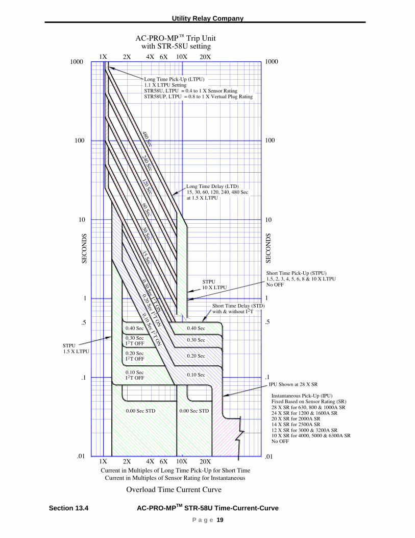
P a g e 19
Section 13.4 AC-PRO-MP
TM STR-58U Time-Current-Curve

AC-PRO-MPTM
Instruction Manual www.utilityrelay.com
P a g e 20
Section 13.5 AC-PRO-MP
TM STR-38S & 58U Ground Fault Time-Current-Curve

Utility Relay Company
P a g e 21
Section 13.6 AC-PRO-MP
TM STR-58U Load Monitoring Time-Current-Curve

AC-PRO-MPTM
Instruction Manual www.utilityrelay.com
P a g e 22
Section 13.7 AC-PRO-MP
TM Quick-Trip
TM Instantaneous Time-Current-Curve

Utility Relay Company
P a g e 23
Section 13.8 AC-PRO-MP
TM Quick-Trip
TM Ground Fault Time-Current-Curve