ac-pro-mp & mp-ii manual - utility relay company · replacement trip units for the str trip...
TRANSCRIPT


AC-PRO-MP® & AC-PRO-MP-II® Instruction Manual www.utilityrelay.com
P a g e 1
WARNING: Low voltage power circuit breakers contain stored energy spring operating mechanisms. For maximum personnel protection when installing and testing this retrofit kit, the following procedures must be followed. Failure to follow these procedures could result in property damage, personal injury, or death. NO work shall be performed on an energized breaker. Only qualified persons, as defined by the National Electric Code, and preferably NETA Certified or Pearl Certified Technicians, who are familiar with the operation and maintenance of low voltage power circuit breakers and their associated switchgear assemblies should perform the installation of this retrofit kit. Completely read and understand all instructions before attempting the installation and testing of this retrofit kit. Personnel are available at Utility Relay Company during normal working hours (Eastern Standard Time) to answer any questions. Turn off and lockout the power source(s) supplying the breaker prior to removing the breaker and attempting any work on the breaker. Follow all lockout and tagging rules of the National Electric Code and all other applicable codes, regulations and work rules. Do not perform any work including charging, closing or tripping or any other function that could cause significant movement of a draw out breaker while it is on the extension rails. For both draw out and bolt-in breakers, trip open and then move the breaker to a well-lighted work area with a sturdy workbench before starting the retrofit. Do not work on a closed breaker or a breaker with the closing springs charged. Trip open the breaker and make sure any stored energy springs are discharged before performing any work. If this is disregarded, the breaker may unexpectedly trip open or the charging springs may discharge, causing severe injuries. Under some circumstances it may be necessary to charge the springs and close the breaker to make/verify certain retrofit adjustments. In those instances, use extreme caution to stay clear of any moving components in case the breaker either purposely or unexpectedly trips open or the charging springs discharge. Refer to the latest edition of the ANSI/NETA Standard for Maintenance Testing Specifications for bolt tightening torque specifications.
01/01/15

Utility Relay Company
P a g e 2
LIMITED WARRANTY
Utility Relay Company warrants that every AC-PRO, ZERO-Hertz, AC-PRO-MP, AC-PRO-MP-II, and AC-PRO-II trip unit and related retrofit kit components (herein collectively referred to as “product”) shall be free from defects in material and workmanship, and will perform as described in Utility Relay Company’s sales literature and Instruction Manuals, under normal use and service for a period of (2) two years from date of invoice. EXCEPT AS SET FORTH HEREIN, IT IS EXPRESSLY AGREED THAT THERE IS NO WARRANTY OF MERCHANTABILITY OR FITNESS FOR A PARTICULAR PURPOSE, AND THERE IS NO OTHER WARRANTY, EXPRESS, IMPLIED OR STATUTORY, BY UTILITY RELAY COMPANY WITH REFERENCE TO THE PRODUCT.
Should any warranty claim arise within the warranty period, contact Utility Relay Company at 888-289-2864 and do the following: 1.) Provide a complete description of the problem with the trip unit or retrofit kit
component. 2.) Provide the Serial Number located on the trip unit from the warranted retrofit kit. 3.) Obtain a Returned Materials Authorization number (RMA) and return shipping
instructions. 4.) Promptly return the defective material to Utility Relay Company.
Warranty Disclaimer and Liability Limitation
As the sole and exclusive remedy, Utility Relay Company will repair or replace the trip unit and/or retrofit component(s) at no cost to the customer during the warranty period. Removal or reinstallation of a warrantied trip unit and/or retrofit component(s) are the responsibility of the customer. The customer is liable and shall pay for shipment of defective products back to Utility Relay Company. In no event shall Utility Relay Company be liable for any special, incidental or consequential damages.
Excluded from this warranty and not warranted by Utility Relay Company in any fashion, either expressed or implied are:
1.) Any product which has been disassembled (except to replace batteries), repaired, tampered with, altered, changed, or modified by persons other than Utility Relay Company’s own authorized service personnel unless repair by others is made with the written consent of Utility Relay Company.
2.) Defects or damage to the Product resulting from wear, tear, misuse, negligence, improper storage, improper testing, impacts, or use with non-approved accessories.
3.) Products used for any other purpose other than originally intended by Utility Relay Company.
Visit www.utilityrelay.com or call 888-289-2864 for latest warranty information.
10/13/15

AC-PRO-MP® & AC-PRO-MP-II® Instruction Manual www.utilityrelay.com
P a g e 3
Table of Contents Manual Rev 7.0
Section: Page 1.0 Introduction ........................................................ 4 2.0 General ............................................................. 5 2.1 Front View ................................................ 5 2.2 Rear View ................................................ 6 2.3 Top View .................................................. 6 3.0 Installation .......................................................... 7 3.1 Remove Front Cover ................................ 7 3.2 Disconnect STR Wiring ............................ 7 3.3 Remove STR Trip Unit ............................. 8 3.4 Installing Voltage Connections (MP-II) ..... 8 3.5 Connect CT Connectors .......................... 9 3.6 Attach AC-PRO-MP or MP-II to Breaker ................................................ 10 3.7 Check Alignment of “Push-to-Reset” Rod ................................ 10 3.8 Auxiliary Wiring Connections ................... 10 3.9 Insert the Auxiliary Terminal Blocks into the Lower Control Unit ............................. 11 3.10 Modify & Install Terminal Block Cover ..... 11 3.11 Installing the Breaker Position Limit Switch .............................................. 12 3.12 Communications connections (MP-II) ...... 14 3.13 Replace Breaker Front Cover .................. 14 4.0 Settings ............................................................. 15 4.1 Change Settings Using the Front Panel ... 15 4.2 Reviewing Settings .................................. 19 4.3 Setting the Time & Date ........................... 19 4.4 USB Interface and InfoPro-MP-II ............. 19 5.0 Normal Operations & Readings ......................... 20 5.1 Current & Voltage Readings .................... 20 5.2 Power & Energy Readings ....................... 20 6.0 QUICK-TRIP® Arc Flash Reduction ................... 21 6.1 Local QUICK-TRIP® Switch ..................... 21 6.2 Remote QUICK-TRIP® (via Communications) .............................. 22 7.0 SAFE-T-TRIP® ................................................. 23 8.0 SLUGGISH BREAKER® Detection .................... 23 9.0 Last Trip Data .................................................... 24
10.0 Replacing the Battery ......................................... 24 11.0 Self-Test Feature ............................................... 25 12.0 Primary & Secondary Injection Testing .............. 25 12.1 Primary Injection Testing ............................ 25 12.2 Secondary Injection Testing ....................... 25
13.0 DINF Instantaneous Trip .................................... 26 14.0 FV Segregated Trip Relay.................................. 27 15.0 ALR Pre-Trip Alarm Relay.................................. 27 16.0 Ic1 & Ic2 Load Monitoring Relays ...................... 27 17.0 Communications (MP-II) .................................... 28 17.1 Communications Components ................. 28 17.2 Communications Wiring ........................... 28 17.3 System Components & Computer Hardware ............................. 28 17.4 Ethernet ................................................... 28 17.5 Modbus Communications Register Map .. 28 17.6 Communications Settings ........................ 28 18.0 InfoPro-MP or MP-II Software ............................ 29 18.1 Firmware Versions & Updates ................. 29 19.0 Warranty ............................................................ 30 20.0 Environmental Ratings ....................................... 30 For latest version, visit: http://www.utilityrelay.com/Side_Bar/Instruction_Manuals.html
Section: Page 21.0 Time Current Curves ....................................... 30 21.1 AC-PRO-MP & MP-II STR-18M TCC .............. 31 21.2 AC-PRO-MP & MP-II STR-28D TCC .............. 32 21.3 AC-PRO-MP & MP-II STR-38S TCC .............. 33 21.4 AC-PRO-MP & MP-II STR-58U TCC .............. 34 21.5 AC-PRO-MP & MP-II STR-38S & 58U GF TCC ................................ 35 21.6 AC-PRO-MP & MP-II STR-58U Load Monitoring TCC ...................... 36 21.7 AC-PRO-MP & MP-II QUICK-TRIP® Instantaneous TCC .................. 37 21.8 AC-PRO-MP & MP-II QUICK-TRIP® GF TCC ................................... 38 21.9 AC-PRO-MP or MP-II Neutral Overload TCC .................................... 39
Utility Relay Company
P a g e 4
1.0 Introduction
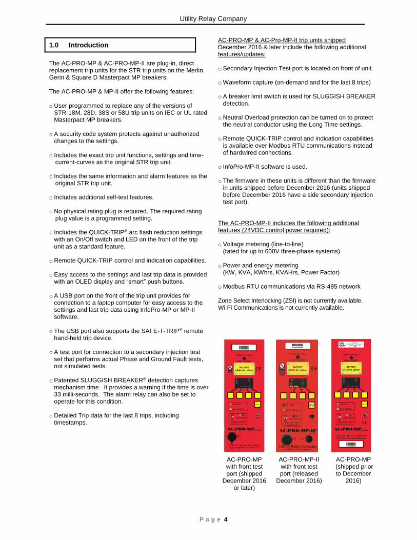
The AC-PRO-MP & AC-PRO-MP-II are plug-in, direct replacement trip units for the STR trip units on the Merlin Gerin & Square D Masterpact MP breakers. The AC-PRO-MP & MP-II offer the following features: o User programmed to replace any of the versions of
STR-18M, 28D, 38S or 58U trip units on IEC or UL rated Masterpact MP breakers.
o A security code system protects against unauthorized
changes to the settings. o Includes the exact trip unit functions, settings and time-
current-curves as the original STR trip unit.
o Includes the same information and alarm features as the original STR trip unit.
o Includes additional self-test features.
o No physical rating plug is required. The required rating plug value is a programmed setting.
o Includes the QUICK-TRIP® arc flash reduction settings with an On/Off switch and LED on the front of the trip unit as a standard feature.
o Remote QUICK-TRIP control and indication capabilities. o Easy access to the settings and last trip data is provided
with an OLED display and “smart” push buttons.
o A USB port on the front of the trip unit provides for connection to a laptop computer for easy access to the settings and last trip data using InfoPro-MP or MP-II software.
o The USB port also supports the SAFE-T-TRIP® remote hand-held trip device.
o A test port for connection to a secondary injection test set that performs actual Phase and Ground Fault tests, not simulated tests.
o Patented SLUGGISH BREAKER® detection captures mechanism time. It provides a warning if the time is over 33 milli-seconds. The alarm relay can also be set to operate for this condition.
o Detailed Trip data for the last 8 trips, including timestamps.
AC-PRO-MP & AC-Pro-MP-II trip units shipped December 2016 & later include the following additional features/updates: o Secondary Injection Test port is located on front of unit.
o Waveform capture (on-demand and for the last 8 trips)
o A breaker limit switch is used for SLUGGISH BREAKER detection.
o Neutral Overload protection can be turned on to protect the neutral conductor using the Long Time settings.
o Remote QUICK-TRIP control and indication capabilities is available over Modbus RTU communications instead of hardwired connections.
o InfoPro-MP-II software is used.
o The firmware in these units is different than the firmware in units shipped before December 2016 (units shipped before December 2016 have a side secondary injection test port).
The AC-PRO-MP-II includes the following additional features (24VDC control power required): o Voltage metering (line-to-line)
(rated for up to 600V three-phase systems)
o Power and energy metering (KW, KVA, KWhrs, KVAHrs, Power Factor)
o Modbus RTU communications via RS-485 network Zone Select Interlocking (ZSI) is not currently available. Wi-Fi Communications is not currently available.
AC-PRO-MP with front test port (shipped
December 2016 or later)
AC-PRO-MP (shipped prior to December
2016)
AC-PRO-MP-II with front test port (released
December 2016)

AC-PRO-MP® & AC-PRO-MP-II® Instruction Manual www.utilityrelay.com
P a g e 5
2.0 General
2.1 Front View
A. Pop-out tripped indicator This indicator is mechanically interlocked to the breaker mechanism and pops out when the breaker is tripped by the trip unit.
After a trip, the pop-out indicator must be pushed to the flush position before the breaker can be closed.
B. Battery Cover
To replace the battery, remove the four (4) 2-56 screws and battery cover, remove the old battery and insert a new CR-P2, 6 Volt Lithium battery. Replace the battery cover and screws. See Section 10.0.
C. OLED Display
The display is normally off. Pushing the DISPLAY button (E) turns on the display.
D. “Smart” Push Buttons
These push buttons perform the functions indicated on the bottom of the OLED display.
E. DISPLAY Push Button
Pushing the DISPLAY button will turn on the display. If no buttons are pushed for 30 seconds, the display will turn off.
F. Red Pre-Trip LED Depending on the magnitude of the largest Phase current, this LED will be: a. Off if less than 90% of LT Pick-Up b. Solidly on if greater than 90% but less than 105%
of LT Pick-Up c. Flashing if greater than 105% of LT Pick-Up
G. Green Self Test OK LED
When the trip unit is powered up, this LED is on unless a problem is detected.
H. USB Connector USB 2.0 Mini-B connector for use with InfoPro-MP or InfoPro-MP-II software and SAFE-T-TRIP® device.
I. QUICK-TRIP® on/off Switch When this switch is in the on position, the QT-I and QT-GF functions are active for reduction of arc flash hazard.
J. Secondary Injection Test Port
Removing the test port cover on the front of the trip unit allows connection of the secondary injection test set
K. Red QUICK-TRIP® on LED
When this LED is on, the QT-I and QT-GF functions are active because either the local (J) or remote QUICK-TRIP function is on.
L. Serial Number
C
D
G
A
B
E
F
I
H
K
J
L
Utility Relay Company
P a g e 6
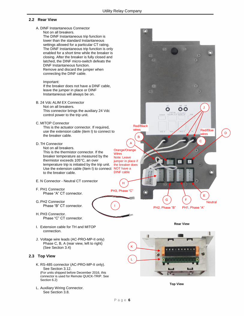
2.2 Rear View
A. DINF Instantaneous Connector Not on all breakers.
The DINF Instantaneous trip function is lower than the standard Instantaneous settings allowed for a particular CT rating. The DINF Instantaneous trip function is only enabled for a short time while the breaker is closing. After the breaker is fully closed and latched, the DINF micro-switch defeats the DINF Instantaneous function. Remove and discard the jumper when connecting the DINF cable. Important: If the breaker does not have a DINF cable, leave the jumper in place or DINF Instantaneous will always be on.
B. 24 Vdc ALIM EX Connector
Not on all breakers. This connector brings the auxiliary 24 Vdc control power to the trip unit.
C. MITOP Connector
This is the actuator connector. If required, use the extension cable (item I) to connect to the breaker cable.
D. TH Connector
Not on all breakers. This is the thermistor connector. If the breaker temperature as measured by the thermistor exceeds 105°C, an over temperature trip is initiated by the trip unit. Use the extension cable (Item I) to connect to the breaker cable.
E. N Connector - Neutral CT connector
F. PH1 Connector
Phase “A” CT connector.
G. PH2 Connector Phase “B” CT connector.
H. PH3 Connector.
Phase “C” CT connector.
I. Extension cable for TH and MITOP connection.
J. Voltage wire leads (AC-PRO-MP-II only) Phase C, B, A (rear view, left to right) (See Section 3.4)
2.3 Top View
K. RS-485 connector (AC-PRO-MP-II only). See Section 3.12.
(For units shipped before December 2016, this connector is used for Remote QUICK-TRIP. See Section 6.2)
L. Auxiliary Wiring Connector.
See Section 3.8.
H
H
K
J
Red/Black wires
Red/Black wires
Orange/Orange Wires Note: Leave jumper in place if the breaker does NOT have a DINF cable
Orange/Orange Wires Note: Leave jumper in place if the breaker does NOT have a DINF cable
PH3, Phase “C”
PH2, Phase “B” PH1, Phase “A” I
I
Top View
Rear View
L
J
G
G
F
F
E
E
B
B
C
C
A
A
J
C
D
C
Red/Blue wires
Neutral
AC-PRO-MP® & AC-PRO-MP-II® Instruction Manual www.utilityrelay.com
P a g e 7
3.0 Installation
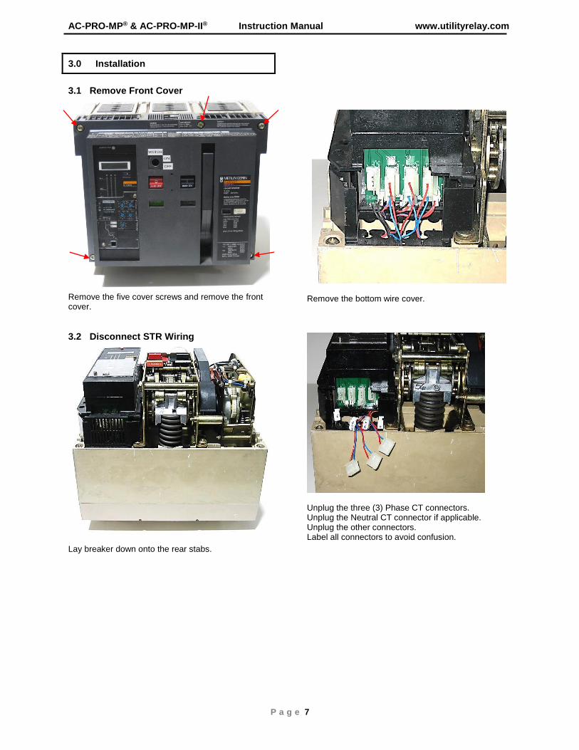
3.1 Remove Front Cover
Remove the five cover screws and remove the front cover.
3.2 Disconnect STR Wiring
Lay breaker down onto the rear stabs.
Remove the bottom wire cover.
Unplug the three (3) Phase CT connectors. Unplug the Neutral CT connector if applicable. Unplug the other connectors. Label all connectors to avoid confusion.

Utility Relay Company
P a g e 8
3.3 Remove the STR Trip Unit
Remove the four (4) screws attaching the STR trip unit to the lower control unit. Un-clip the two (2) wire-way latches and pull out the wires. Remove the right terminal block cover.
Slide out the three terminal blocks from the lower control unit.
3.4 Installing the Voltage Connections (AC-PRO-MP-II) Locate the 3-pole fuse block on the existing trip unit mounting carriage as shown. Using the two (2) round holes in the fuse block as a guide, mark the location of the two (2) round holes on the trip unit carriage.
Drill and tap two (2) 8-32 holes in the trip unit carriage where marked.
Mount the 3-pole fuse block to the trip unit carriage using two (2) 8-32 x 1-1/8 Male/Female standoffs and lock washers as shown.
Fuse Block Installation (AC-PRO-MP-II only)
Run #20 AWG SIS wire from the 3-pole fuse block thru the breaker using the same path as the existing CT wires. Connect to the line side of the breaker existing screws as shown using the ring tongue terminals provided. Connect to the 3-pole fuse block using the ring tongue terminals provided. It is very important to maintain proper phasing.
It is VERY important to maintain the proper
phasing of the voltage wiring
Fuse Block to Breaker Wiring (AC-PRO-MP-II)
Connect the wires from the rear of the trip unit to the 3-pole fuse block using the ring tongue terminals provided.
DINF Switch & Inertial Mass
Un-clip
Remove TB Cover
Slide out TBs
STR Trip Unit
Lower Control Unit
DINF Cable
(2) 8-32 x 1-1/8 Male/ Female Standoffs and lock washers
Breaker Back Plate
Existing Screw on Breaker Line Side
3-Pole Fuse Block
#20 SIS Wire from Fuse Block
PH1(A)
PH2(B)
PH3(C)
PH1(A) PH2(B) PH3(C)

AC-PRO-MP® & AC-PRO-MP-II® Instruction Manual www.utilityrelay.com
P a g e 9
Install the three (3) T-306-4 Fuses (Buss KTK-R-1) into the 3-pole fuse block. After the wiring to the 3-pole fuse block is complete, attach the fuse block cover to the 3-pole fuse block using two (2) 8-32 x 3/8 Phillips HD SEMS screws as shown.
Trip Unit to Fuse Block Wiring (AC-PRO-MP-II)
Voltage Connections Diagram (AC-PRO-MP-II)
3.5 Connect CT Connectors
Connect the three (3) Phase CT connectors. Connect the Neutral CT connector if applicable. Connect the other connectors being very careful not to mix up the connectors. If necessary, use the extension cables for the TH and MTOP connections. See the wire color codes in Section 3.2.
For those breakers that do not have a DINF Switch and inertial mass, leave the jumper in the DINF connector. Without the jumper DINF Instantaneous will always be on. Otherwise, remove and discard the jumper and connect the DINF cable to the DINF connector.
DINF Jumper
Back of AC-PRO-MP
(2) 8-32 x 3/8 Phillips SEMS screws
Trip Unit to Fuse Block Wires
Fuse Block Cover
Fuse Block to Breaker Line Side Wires

Utility Relay Company
P a g e 10
3.6 Attach the AC-PRO-MP® to Breaker.
Set the AC-PRO-MP® in place and attach using four (4) M3 X 16 Phillips screws.
3.7 Check Alignment of “Push-to-Reset” Rod.
Check for proper alignment of the back of the “Push-to-Reset” rod with the small reset piece in the lower control unit.
3.8 Auxiliary Wiring Connections.
Snap the connectors out of the three (3) plastic terminal blocks. The plastic terminal blocks will be reused. Do not remove the Neutral CT terminals T1 & T2 if installed. See Auxiliary Terminal Block Wiring on next page.
Snap the new terminals into the existing slide in plastic terminal blocks. Follow the connection diagram on Page 8. Make sure the terminals are fully seated in the plastic terminal blocks. Insert the assembled auxiliary wiring connector into position on top of the AC-PRO-MP.
Check alignment with mechanism
Snap connectors out of 3 plastic terminal blocks
Snap new connectors into the 3 plastic terminal blocks
Auxiliary Wiring connector shown without wires
Insert Auxiliary Wiring connector in AC-PRO-MP
Auxiliary Wiring Connector with Wires

AC-PRO-MP® & AC-PRO-MP-II® Instruction Manual www.utilityrelay.com
P a g e 11
3.9 Insert the Auxiliary Terminal Blocks into the Lower Control Unit.
Insert the terminal blocks into their proper location in the lower control unit. Follow the diagram below.
3.10 Modify and Install Terminal Block Cover.
Cut off the bottom portion of the right terminal block cover previously removed.
Replace the terminal block cover using the existing screw.
V1V2 C
LR1 R2LR2
R1
6
V1 V2 LR1LR2 C R2 R1
Top Front AuxiliaryWiring Connector
Control Unit
AC-PRO-MP OR MP-IITop View
Lower
Neutral CT LeadsT2 (Red)T1 (White)
(Do Not Remove)
Front of AC-PRO-MP or MP-II
ORIGINALCOMM & ZSI
(not used by
AC-PRO-MP or MP-II) NC NO C
PCB-ST-66.0
CA-2-300-3
Breaker Position
Limit Switch
(shown with breaker
open and switch
lever pushed in)
Cable HarnessLimit Switch terminals
(units shipped
December 2016 or later)
Auxiliary Terminal Block Wiring
Cut
Before
After
Replace TB cover
Insert TBs

Utility Relay Company
P a g e 12
3.11 Installing the Breaker Position
Limit Switch A limit switch is provided as a breaker position input, for AC-PRO-MP or MP-II trip units shipped in December 2016 or later. This limit must be installed for the following: 1) To provide breaker open or closed information to
the communications system. 2) To enable “SLUGGISH BREAKER” detection. The patented “SLUGGISH BREAKER” detection feature measures the breaker mechanism operating speed for every trip operation initiated by the trip unit including the important “First Operation”. If the mechanism operation time is longer than the programmed time, the trip unit will provide a SLUGGISH BREAKER (MAINTENANCE REQUIRED) alarm.
Install the limit switch on the breaker as follows: Make sure the breaker is open. Attach the MP-101 Limit Switch Mounting Bracket to the MP-100 Adapter Bracket using two (2) 4-40 x ¾ Socket HD Cap screws and lock washers. The limit switch mounting bracket assembly mounts on the right side of the breaker mechanism using an existing hole in the breaker mechanism horizontal support plate. Slide the limit switch mounting bracket assembly onto the breaker mechanism horizontal support plate so that the support plate goes thru the gap in the bracket assembly as shown. Attach the bracket assembly to the support plate using one (1) 4-40 x 3/8 Phillips HD screw and lock washer.
Limit Switch Mounting
Bracket Installation
The breaker mechanism may have an existing connecting arm to the auxiliary contacts. Follow the appropriate instructions below for the breaker type being retrofitted. If the breaker does NOT have an auxiliary contact connecting arm: The limit switch flag mounts to an existing hole in the breaker mechanism. Place one (1) 6mm dia. x 6mm lg. Shoulder screw thru the hole and lock the shoulder screw in place using one (1) Nylon spacer, one (1) M6 lock washer and one (1) Black Delrin Rod as shown below. Securely tighten the flag assembly.
Limit Switch Flag Installation (breaker WITHOUT Auxiliary contact arm)
If the breaker DOES have an auxiliary contact connecting arm: Remove the existing auxiliary contact connecting arm by removing the e-rings holding the arm in place. Remove the pin from the end of the connecting arm that connects to the breaker mechanism and use a 6mm diameter drill to enlarge the hole in the end of the connecting arm that the pin was removed. Reattach the connecting arm to the auxiliary contact using the existing e-ring. The limit switch flag mounts in an existing hole in the breaker mechanism. Place one (1) 6mm dia. x 6mm lg. Shoulder screw thru the hole in the breaker mechanism and the connecting arm. Lock the shoulder screw in place using one (1) M6 lock washer and one (1) Black Delrin Rod as shown. Securely tighten the flag assembly.
MP-100 Adapter Plate
Breaker Mechanism Horizontal Support Plate
Black Delrin Rod and Lock washer
Nylon Spacer
6mm dia. x 6mm Lg. Shoulder screw
MP -101 Limit Switch Mounting Bracket Assembly

AC-PRO-MP® & AC-PRO-MP-II® Instruction Manual www.utilityrelay.com
P a g e 13
Limit Switch Flag Installation (breaker WITH Auxiliary contact arm)
Attach the limit switch circuit board to the mounting bracket assembly using two (2) 6-32 x 3/8 Phillips HD Cap screws and lock washers. See the photo. Adjust the location of the circuit board left or right until the limit switch changes state or “clicks” against the limit switch flag. Securely tighten the hardware to hold the circuit board in location.
Limit Switch Circuit Board Installation
Wire the 2-pole terminal block on the limit switch circuit board to terminals 9 and 10 of the TRIP UNIT I/O connector as shown on page 8. Polarity is NOT important. Use the CA-2-300-3 Cable Harness provided with two (2) 22 AWG wires in a PVC tube.
Limit Switch Wiring
CA-2-300-3 Cable Harness
Terminals 9 and 10 of I/O Connector
Limit Switch Mounting Bracket Assembly
4-40 x 3/8 Phillips HD screw and lock washer
Limit Switch Circuit Board
(2) 6-32 x 3/8 Phillips HD Screws and lock washers
Auxiliary Contact Connecting Arm
Black Delrin Rod and Lock Washer
6mm dia x 6mm Lg. Shoulder Screw
Utility Relay Company
P a g e 14
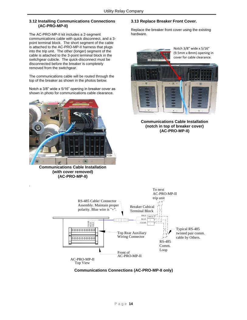
3.12 Installing Communications Connections (AC-PRO-MP-II) The AC-PRO-MP-II kit includes a 2-segment communications cable with quick disconnect, and a 3-point terminal block. The short segment of the cable is attached to the AC-PRO-MP-II harness that plugs into the trip unit. The other (longer) segment of the cable is attached to the 3-point terminal block in the switchgear cubicle. The quick-disconnect must be disconnected before the breaker is completely removed from the switchgear. The communications cable will be routed through the top of the breaker as shown in the photos below. Notch a 3/8” wide x 5/16” opening in breaker cover as shown in photo for communications cable clearance.
Communications Cable Installation
(with cover removed) (AC-PRO-MP-II)
3.13 Replace Breaker Front Cover. Replace the breaker front cover using the existing hardware.
Communications Cable Installation (notch in top of breaker cover)
(AC-PRO-MP-II)
.
Top Rear AuxiliaryWiring Connector
AC-PRO-MP-IITop View
Front of AC-PRO-MP-II
CL
EA
R
BL
UE
SH
LD
To nextAC-PRO-MP-II
trip unit
RS-485Comm.Loop
Typical RS-485
twisted pair comm.
cable by Others.
RS-485 Cable/ Connector
Assembly. Maintain proper
polarity. Blue wire is "+".
-
+
SHLD
CLEAR
BLUE
SHLD
Breaker Cubical
Terminal Block
Communications Connections (AC-PRO-MP-II only)
Notch 3/8” wide x 5/16” (9.5mm x 8mm) opening in cover for cable clearance.

AC-PRO-MP® & AC-PRO-MP-II® Instruction Manual www.utilityrelay.com
P a g e 15
4.0 Settings
The trip unit is shipped un-commissioned and must be commissioned before placing in service. The push buttons and display on the front panel or the USB Interface with a laptop computer can be used to make the initial settings or change existing settings.
4.1 Change Settings Using the Front Panel Push the “DISPLAY” button to power up the trip unit. The following is displayed if the unit has not been commissioned yet:
If the unit was already commissioned, the following screen will be displayed:
Push the “Set” button at the “**WARNING** – Enter settings” screen. Or push the “Chng” button at the “**SETTINGS**” screen to display the security window:
The Security Code is the last four (4) digits of the Serial Number. See Section 2.1 for the location of the Serial Number.
Push the “Up” or “Down” button to select the value of each digit. Use the “Next” button to advance to the next digit. For the last digit, the following is displayed:
Push the “Enter” button after the last digit of the Security Code is entered. The following is displayed:
Push the “Up” or “Down” buttons until the desired STR trip unit type is flashing. The other STR types are displayed by pushing the “Up” button several times.
After pushing “Enter”, the following is displayed:
Select the system frequency (50 or 60 Hz).
**** IMPORTANT **** The trip unit will NOT FUNCTION as it is shipped from the factory. The user must first COMMISSION the unit as outlined in this Section to make it functional.
**** IMPORTANT **** The trip unit will NOT FUNCTION as it is shipped from the factory. The user must first COMMISSION the unit as outlined in this Section to make it functional.
** “WARNING” **
Enter Settings Before
Placing In Service
Push “Set”
Set
** “WARNING” **
Enter Settings Before
Placing In Service
Push “Set”
Set
Security Code
To change settings
enter 4 digit code
0 _ _ _
Up Dwn Next Exit
Security Code
To change settings
enter 4 digit code
0 _ _ _
Up Dwn Next Exit
SECURITY CODE
To Change Settings
Enter 4 Digit Code
X X X X
Up Dwn Enter
SECURITY CODE
To Change Settings
Enter 4 Digit Code
X X X X
Up Dwn Enter
SELECT STR TYPE:
STR 38S RatingPlug
STR 58U NoRatingPlug
STR 58U RatingPlug
Up Dwn Exit Enter
SELECT STR TYPE:
STR 38S RatingPlug
STR 58U NoRatingPlug
STR 58U RatingPlug
Up Dwn Exit Enter
SElECT STR TYPE:
STR 18M
STR 28D NoRatingPlug
STR 28D RatingPlug
STR 38S NoRatingPlug
Up Dwn Exit Enter
SElECT STR TYPE:
STR 18M
STR 28D NoRatingPlug
STR 28D RatingPlug
STR 38S NoRatingPlug
Up Dwn Exit Enter
** SETTINGS **
“Rev” to Review
“Chng” to Change
“Exit” to Cancel
Rev Chng Exit
Set
** Frequency **
Frequency: 60 Hz
60 50 Back Enter
** Frequency **
Frequency: 60 Hz
60 50 Back Enter

Utility Relay Company
P a g e 16
After pushing “Enter”, the following is displayed: (Not for 18M or 28D)
The H1/N1 breakers have standard or special interrupting rating and the H2 breakers have high interrupting rating. After pushing “Enter”, the following is displayed:
Use the “Up” and “Down” buttons to enter the correct CT Rating.
After pushing “Enter”, the following is displayed: (Not for 18M or non-rating plug versions)
Use the “Up” and “Down” buttons to enter the desired Virtual Rating Plug rating. After pushing “Enter”, the following is displayed: (Not for 18M)
Use the “Up” and “Down” buttons to enter the desired Long Time Pick-Up (LTPU) value.
After pushing “Enter”, use the “Up” and “Down” buttons to enter the desired Long Time Delay (LTD). After pushing “Enter”: For trip units shipped in December 2016 or later:
The Neutral Overload Protection On/Off setting will appear: use the “On” and “Off” buttons that appear to turn Neutral Overload on or off. (does not apply to 18M). If Neutral Overload is turned on, “(Requires Neutral CT)” will appear.
For AC-PRO-MP trip units shipped before
December 2016: After setting the Long Time Delay, the next
screen will be Short Time settings. Next, for Short Time Settings, the following is displayed: (Not for 18M or 28D)
Use the “Up” and “Down” buttons to enter the desired Short Time Pick-Up (STPU) value. After pushing “Enter”, use the “On” and “Off” buttons that appear to enter I2T ramp on or off. After pushing “Enter”, use the “Up” and “Down” buttons to select the desired Short Time Delay (STD). After pushing “Enter”, the following is displayed: (Not for 18M or 28D)
Use the “T/W” button to switch between the two types of Ground Fault protection. “T” is for the normal 3-Wire or 4-Wire residual
Ground Fault. “W” is for source ground return Ground Fault.
Note: if type “W” is selected, Neutral Overload will automatically be turned OFF and “(Disables Neutral OL)” will be displayed.
Breaker Type: H2
H1/N1 H2 Back Enter
Breaker Type: H2
H1/N1 H2 Back Enter
CT Rating:
XXXX Amp
** IMPORTANT **
Must match actual
Tap on breaker CTs
Up Dwn Back Enter
CT Rating:
XXXX Amp
** IMPORTANT **
Must match actual
Tap on breaker CTs
Up Dwn Back Enter
**** IMPORTANT **** The CT Rating entered MUST match the rating of the CTs in the breaker.
**** IMPORTANT **** The CT Rating entered MUST match the rating of the CTs in the breaker.
Select
Virtual Rating Plug:
XXXX Amp
Up Dwn Back Enter
Select
Virtual Rating Plug:
XXXX Amp
Up Dwn Back Enter
Long Time (LT):
Pick-Up: XXXX Amp
Delay: XXX Sec
Neutral OL: XXX
Up Dwn Back Enter
Long Time (LT):
Pick-Up: XXXX Amp
Delay: XXX Sec
Neutral OL: XXX
Up Dwn Back Enter
Short Time (ST):
Pick-Up: XXXX Amp
I2T Ramp: OFF
Delay: X.XX Sec
Up Dwn Back Enter
Short Time (ST):
Pick-Up: XXXX Amp
I2T Ramp: OFF
Delay: X.XX Sec
Up Dwn Back Enter
Ground Fault (GF)
Type: T (Residual)
T/W Off Back Enter
Ground Fault (GF)
Type: T
T/W Off Back Enter

AC-PRO-MP® & AC-PRO-MP-II® Instruction Manual www.utilityrelay.com
P a g e 17
After pushing “Enter”, the following is displayed: (Not for 18M or 28D)
Use the “Up” and “Down” buttons to enter the desired Ground Fault (GFPU) Pick-Up value. The maximum GFPU is 1200 Amp. A GFPU setting less than 25% of the CT rating requires 24Vdc external power. After pushing “Enter”, use the “On” and “Off” buttons that appear to enter I2T ramp on or off. After pushing “Enter”, use the “Up” and “Dwn” buttons to select the desired Ground Fault Delay (GFD). After pushing “Enter”, the following is displayed:
Use the “Up” and “Down” buttons to enter the desired Instantaneous Pick-Up (IPU) value.
After pushing “Enter”, the following is displayed:
Use the “Up” and “Down” buttons to enter the desired QUICK-TRIP Instantaneous Pick-Up (QT-I) value. An off setting is not available. After pushing “Enter”, the following is displayed: (Not for 18M or 28D)
Use the “On/Off” button to toggle between “On” or “Off” for the QUICK-TRIP® Ground Fault function. If the normal GF was previously set to “Off”, the following will be displayed instead of the above display. (Not for 18M or 28D)
Use the “On/Off” button to turn the QUICK-TRIP® Ground Fault function on or off. Use the “T/W” button to select the type of Ground Fault. “T” is for the normal 3-Wire or 4-Wire residual
Ground Fault. “W” is for source ground return Ground Fault. After pushing “Enter”, the following is displayed: (Not for 18M or 28D)
Use the “Up” or “Down” buttons to select the desired QUICK-TRIP Ground Fault (QT-GF) Pick-Up value. A QT-GF setting less than 25% of the CT rating requires 24Vdc external power.
After pushing “Enter”, the following is displayed: (Not for 18M, 28D or 38S)
See Section 16.0 for more information on the Load Monitoring relays. Use the “Up” or “Down” buttons to select the desired Load Monitoring 1 (Ic1) Pick-Up or scroll down to off.
Ground Fault (GF):
Pick-Up: XXXX Amp
I2T Ramp: OFF
Delay: X.XX Sec
Up Dwn Back Enter
Ground Fault (GF):
Pick-Up: XXXX Amp
I2T Ramp: OFF
Delay: X.XX Sec
Up Dwn Back Enter
Instantaneous (I):
Pick-Up: XXXXX Amp
Up Dwn Back Enter
Instantaneous (I):
Pick-Up: XXXXX Amp
Up Dwn Back Enter
Quick-Trip (QT):
QT-I: XXXXX Amp
Up Dwn Back Enter
Quick-Trip (QT):
QT-I: XXXXX Amp
Up Dwn Back Enter
QT Ground Fault (GF):
Type: T (Residual)
On/Off Back Enter
QT Ground Fault (GF):
Type: XXX
On/Off Back Enter
Quick-Trip (QT):
QT-I: XXXXX Amp
QT-GF: XXXX Amp
Up Dwn Back Enter
Enter
Quick-Trip (QT):
QT-I: XXXXX Amp
QT-GF: XXXX Amp
Up Dwn Back Enter
Enter
QT Ground Fault (GF):
Type: T (Residual)
T/W On/Off Back Enter
QT Ground Fault (GF):
Type: T/W
T/W On/Off Back Enter
Load Monitoring
Ic1: XXXX Amp
Ic2: XXXX Amp
Up Dwn Back Enter
Enter
Load Monitoring
Ic1: XXXX Amp
Ic2: XXXX Amp
Up Dwn Back Enter
Enter

Utility Relay Company
P a g e 18
Push the “Enter” button to go to Load Monitoring 2 (Ic2). Use the “Up” or “Down” buttons to select the desired Ic2 Pick-Up or scroll down to off. After pushing “Enter”, the following is displayed:
See Section 14.0 for more information on the FV Segregated Trip relay. Use the “Yes” or “No” buttons to select which combinations of protective functions will operate the FV Segregated Trip Relay. The FV Segregated Trip Relay requires 24Vdc external power to operate. Use the “Down” button to move to the next function. When the “Down” button is pushed after the “GF Trip” FV Segregated Trip Relay operation is selected, the following is displayed:
Use the “Yes” or “No” buttons to select which combinations of functions will operate the FV Segregated Trip Relay. Use the “Down” button to move to the next function.
After setting the “Neutral OL” function, pushing the “Down” button will display the following: (this screen only applies to AC-PRO-MP-II)
The AC-PRO-MP-II is capable of communicating over an RS485 network via Modbus RTU protocol. The RS485 communications settings are as follows: Communications Enabled: Set to ON if RS485 communications will be used. Address: Each trip unit that shares the same twisted pair must have a unique address. The address identifies each individual trip unit. Note: two trip units can have the same Address as long as they are not connected to the network via the same twisted pair cable. The address is selectable from 1 to 247, in increments of 1. In most applications, only addresses 1 through 32 will be used due to the limitations of RS485 communications. Baud Rate should be selected to match the baud rate of the master communicating device (i.e. PC, gateway, etc.). Parity should be set to match the parity of the master communicating device (i.e. PC, gateway, etc.). Reply Delay is the minimum delay between the trip unit’s receipt of a Modbus packet and its reply. It can be set to 5 or 10 milliseconds. After setting the Reply Delay, pushing the “Enter” button will display the following: (this screen only applies to AC-PRO-MP-II)
The AC-PRO-MP-II “Controls Over Comm” settings are locally set “permissive settings”, which should normally be set to OFF, unless there is a communications master device in place that is specifically intended and capable of performing these functions. Forced Trip: If enabled, this feature permits tripping of the breaker via a forced trip command over RS485 communications. Settings Change: If enabled, this feature permits the user to make settings changes via the communications network. Otherwise, settings can only be changed at the AC-PRO-MP-II using the smart buttons or using the local USB connection. NOTE: The CT settings can only be changed at the AC-PRO-MP-II.
QT Control: If enabled, this permits turning QUICK-TRIP settings ON over RS485 communications.
FV Segregated Trip
Relay Operation On:
LT Trip: XXX
ST Trip: XXX
I Trip: XXX
GF Trip: XXX
Yes No Up Dwn
Enter
FV Segregated Trip
Relay Operation On:
LT Trip: XXX
ST Trip: XXX
I Trip: XXX
GF Trip: XXX
Yes No Up Dwn
Enter
FV Segregated Trip
QT-I Trip: XXX
QT-GF Trip: XXX
OverTemp Trip: XXX
Sluggish Brkr: XXX
Neutral OL: XXX
Yes No Up Dwn
FV Segregated Trip
QT-I Trip: XXX
QT-GF Trip: XXX
OverTemp Trip: XXX
Sluggish Brkr: XXX
Neutral OL: XXX
Yes No Up Dwn
RS-485 Communications
Enabled: OFF
Address: 1
Baud Rate: 19200
Parity: None
Reply Delay: 5 ms
On Off Back Enter
FV Segregated Trip
QT-I Trip: XXX
QT-GF Trip: XXX
OverTemp Trip: XXX
Sluggish Brkr: XXX
Neutral OL: XXX
Yes No Up Dwn
Controls Over Comm:
Forced Trip: OFF
Settings Change: OFF
QT Control: OFF
On Off Back Enter

AC-PRO-MP® & AC-PRO-MP-II® Instruction Manual www.utilityrelay.com
P a g e 19
After setting QT Control, pushing the “Enter” button will display the following:
Pushing the “Review” button will review the settings just made and will allow changes to be made.
Pushing the “Save” button will save the settings into non-volatile memory and the following will be displayed for a short time:
4.2 Reviewing Settings The trip unit settings and information can be reviewed in a “read only” manner, using the Review Settings button.
Push the “Rev” button at the “**SETTINGS**” screen to start reviewing the trip unit information and settings. After pushing “Rev”, the following will be displayed:
Push the “Next” button to continue reviewing trip unit settings. The subsequent screens will display all
settings, along with the “Next”, “Back”, and “Exit” buttons.
4.3 Setting the Time & Date The AC-PRO-MP & MP-II include an internal clock that is powered by the 6V CR-P2 battery. The time and date setting is important, as trip events and on-demand waveforms are time stamped. The time and date must be set after commissioning the trip unit or after replacing the battery The clock does not automatically update for daylight savings time. To view or change the time, push the “Display” button (and possibly the “Exit” button) to view the main screen:
Push the “Time” button to display the time and date:
Where “hh:mm:ss” is the time of day in hour, minutes and seconds. Where “MM/DD/YYYY” is the date in month, day and year. To change the time, push the “Chng” button and follow the prompts.
4.4 Using the USB Interface A USB 2.0, Mini-B connector on the front of the AC-PRO-MP & MP-II trip units is used to transfer information, including settings, between the trip unit and a computer, using InfoPro software. See Section 18.0. The USB port also supports the SAFE-T-TRIP®
remote hand-held device. See Section 7.0 for additional information.
Save Settings
Or
Review Settings
Exit Review Save
Save Settings
Or
Review Settings
Exit Review Save
USER SETTINGS UPDATE
….Successful
USER SETTINGS UPDATE
….Successful
ϕA XXXX A XXX Vab
ϕB XXXX A XXX Vbc
ϕC XXXX A XXX Vca
N: XXXX A
GF: XXXX A
Pwr Set Hist Time
ϕA XXXX A
ϕB XXXX A
ϕC XXXX A
N: XXXX A
GF: XXXX A
Set Hist Time
Time & Date:
hh:mm:ss AM/PM
MM/DD/YYYY
Chng Exit
Time & Date:
hh:mm:ss AM/PM
MM/DD/YYYY
Chng Exit
** SETTINGS **
“Rev” to Review
“Chng” to Change
“Exit” to Cancel
Rev Chng Exit
Set
Serial No: xxxxxxxxxx
Firmware: Vx.xx.xxx
STR TYPE: STR xxx
Frequency: 60 Hz
Breaker: Hx
Next Exit
FV Segregated Trip
QT-I Trip: XXX
QT-GF Trip: XXX
OverTemp Trip: XXX
Sluggish Brkr: XXX
Neutral OL: XXX
Yes No Up Dwn

Utility Relay Company
P a g e 20
5.0 Normal Operations & Readings
5.1 Current & Voltage Readings During normal operation, the trip unit display screen will be off and in its power saving mode. When the “DISPLAY” button is pressed during normal operation (no trips, errors, alarms, etc), the trip unit will display currents and voltages. The voltages will be displayed if 24VDC control power is present, and if the voltage hardware is present. The neutral and GF currents will only be displayed if neutral or GF protective functions are turned on. See below. The “XXXX” digits will display actual readings.
Main (“Readings”) Screen (voltages appear on AC-PRO-MP-II only)
• The left column displays Currents in Amps for Phases A, B, C, Neutral and Ground Fault.
• The right column displays Line-to-Line Voltages “Vab”, “Vbc”, and “Vca”. These values appear for AC-PRO-MP-II only.
Breaker Current Less than 10% of CT Rating: When the currents are less than about 10% of the CT rating, the display will display “LOW” for currents. Breaker Current Greater than 10% of CT Rating: If the breaker current is greater than about 10% of the CT rating, the current readings will be displayed. Line-to-Line Voltages (if AC-PRO-MP-II and powered with 24VDC): “LOW” will be displayed if the Line-to-Line voltage is 50V or below. “N/A” will be displayed if the Voltage cannot be determined, most likely because system voltage (i.e. 480V) is not present at the AC-PRO-MP-II, or if 24VDC control power is not present. The AC-PRO-MP-II is rated for up to 600V three-phase power systems.
Power & Energy Screen (AC-PRO-MP-II only)
5.2 Power and Energy Values (AC-PRO-MP-II powered by 24VDC):
• KWHr = KiloWatt-Hours (real power usage)
• KVAHr = KiloVolt-Ampere-Hours (apparent power usage)
• KW = KiloWatts (instantaneous real power)
• KVA = KiloVolt-Amperes (instantaneous apparent power)
• PF = total instantaneous Power Factor
• “LOW” is displayed for the per-phase KW and KVA values if an associated phase current or voltage is “LOW”.
• “N/A” will be displayed for KW and KVA values if the Voltage on the associated phase cannot be determined, most likely because system voltage (i.e. 480V) is not present at the trip unit, or 24VDC is not available.
• Energy values increment if the current for a particular phase is above 3% of the CT rating and the phase voltage is above 50V.
• The KWHr value increments (up) and decrements (down) depending on the power flow direction.
• The KVAHr value only increments (up).
• Note: Energy values can increment (up) even when the Instantaneous Power values displayed are “LOW”
ϕA XXXX A XXX Vab
ϕB XXXX A XXX Vbc
ϕC XXXX A XXX Vca
N: XXXX A
GF: XXXX A
Pwr Set Hist Time
ϕA XXXX A
ϕB XXXX A
ϕC XXXX A
N: XXXX A
GF: XXXX A
Set Hist Time
KWHr: XXXXXXXX
KVAHr: XXXXXXXX
KW: XXXX
KVA: XXXX
PF: XX%
Back Reset

AC-PRO-MP® & AC-PRO-MP-II® Instruction Manual www.utilityrelay.com
P a g e 21
6.0 QUICK-TRIP Arc Flash Reduction
The QUICK-TRIP® system (patents 7,646,575 & 7,889,474) is a manually controlled arc flash hazard reduction system. It can reduce trip times when turned on and allows selective coordination between circuit breakers when turned off. If maintenance personnel must work on energized equipment, they will first turn the QUICK-TRIP system on at the breaker feeding the equipment. If a fault now occurs, the upstream breaker will trip quickly based on the QUICK-TRIP settings reducing the Arc Flash Hazard to personnel. When the work is finished, the QUICK-TRIP® system is turned off and the original selective coordination is back in effect. When QUICK-TRIP® is on, the following settings are enabled:
• QUICK-TRIP Instantaneous (QT-I)
• QUICK-TRIP Ground Fault (QT-GF) All other settings remain in effect. The “QUICK-TRIP ON LED” provides positive indication that the QUICK-TRIP settings are active if the LED is on.
6.1 QUICK-TRIP® Switch The QUICK-TRIP switch on the front of the AC-PRO-MP can be used to turn the QUICK-TRIP functions on or off.
J. QUICK-TRIP on/off Switch
Move this switch to the on position to make the QT-I and QT-GF functions active for reduction of arc flash hazard.
K. Red QUICK-TRIP on LED When this LED is on, the QT-I and QT-GF functions are active because either the local (J) or remote QUICK-TRIP switch is in the on position.
If the trip unit is not powered-up because of low breaker current and no 24Vdc auxiliary control power to the breaker, the QUICK-TRIP on LED will not be illuminated with the switch in the on position. To verify that the QUICK-TRIP function will be active as soon as the trip unit powers up with breaker current, push the “Display” button (E) to power the trip unit using the battery. The QUICK-TRIP on LED will illuminate.
**** IMPORTANT ****
A qualified engineer must determine the QUICK-TRIP® settings, calculate the incident energy levels and determine the Hazard Risk Categories (HRC) with QUICK-TRIP® both on and off.
K
J

Utility Relay Company
P a g e 22
6.2 Remote QUICK-TRIP® The QUICK-TRIP system can also be controlled remotely. Either the local QUICK-TRIP switch on the front of the AC-PRO-MP or MP-II or the remote QUICK-TRIP switch/function can turn on QUICK-TRIP. Both must be in the off position to turn QUICK-TRIP off. Remote QUICK-TRIP indication is also possible. This lamp will be energized whenever QUICK-TRIP is on, either by the local on/off switch or the remote QUICK-TRIP switch/function.
For trip units sold in December 2016 or later: Remote QUICK-TRIP control and indication can only be accomplished using Modbus Communications with AC-PRO-MP-II. For details see the AC-PRO-MP-II Modbus Communications Register Map. Note: The “QT Control over Comm” (permissive) setting must be enabled at the trip unit locally before Remote QUICK-TRIP over communications can be utilized. For AC-PRO-MP trip units sold prior to December 2016: Remote QUICK-TRIP is accomplished with wiring, as shown in the diagram below. The remote indication lamp must use 150 milli-Amp or less current. A 40 to 125 Volt, AC or DC source is required for the remote QUICK-TRIP switch and the remote indication lamp. Connections for the remote QUICK-TRIP switch and the remote indication lamp are made to the remote QUICK-TRIP connector on the top of the AC-PRO-MP.
Remote Quick-Trip Connector
40-125 VoltAC/DC
40-125 VoltAC/DC
150 mA Max
AC-PRO-MP Front
Remote Quick-Trip on/off Switch & Indication Light
ON/OFF
Remote QUICK-TRIP wiring
(only applies to units shipped prior to December 2016)
Note: This wiring does not apply to units that have the front test port. Miswiring WILL result in damage.
NOTE: Hardwired remote QUICK-TRIP®
is not available in the AC-PRO-MP & MP-II units with the front test port (shipped December 2016 and later).
AC-PRO-MP® & AC-PRO-MP-II® Instruction Manual www.utilityrelay.com
P a g e 23
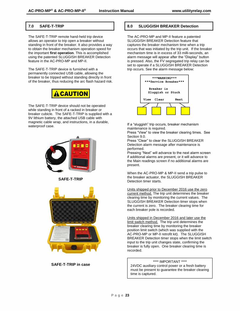
7.0 SAFE-T-TRIP
The SAFE-T-TRIP remote hand-held trip device allows an operator to trip open a breaker without standing in front of the breaker. It also provides a way to obtain the breaker mechanism operation speed for the important first operation. This is accomplished using the patented SLUGGISH BREAKER Detection feature in the AC-PRO-MP and MP-II. The SAFE-T-TRIP device is furnished with a permanently connected USB cable, allowing the breaker to be tripped without standing directly in front of the breaker, thus reducing the arc flash hazard risk.
The SAFE-T-TRIP device should not be operated while standing in front of a racked in breaker or breaker cubicle. The SAFE-T-TRIP is supplied with a 9V lithium battery, the attached USB cable with magnetic cable wrap, and instructions, in a durable, waterproof case.
SAFE-T-TRIP
SAFE-T-TRIP in case
8.0 SLUGGISH BREAKER Detection
The AC-PRO-MP and MP-II feature a patented SLUGGISH BREAKER Detection feature that captures the breaker mechanism time when a trip occurs that was initiated by the trip unit. If the breaker mechanism time is in excess of 33 milli-seconds, an alarm message will appear after the “Display” button is pressed. Also, the FV segregated trip relay can be set to operate if a SLUGGISH BREAKER Detection trip occurs. See the alarm message below:
If a “sluggish” trip occurs, breaker mechanism maintenance is required. Press “View” to view the breaker clearing times. See Section 9.0. Press “Clear” to clear the SLUGGISH BREAKER Detection alarm message after maintenance is performed. Pressing “Next” will advance to the next alarm screen if additional alarms are present, or it will advance to the Main readings screen if no additional alarms are present. When the AC-PRO-MP & MP-II send a trip pulse to the breaker actuator, the SLUGGISH BREAKER Detection timer starts. Units shipped prior to December 2016 use the zero current method. The trip unit determines the breaker clearing time by monitoring the current values. The SLUGGISH BREAKER Detection timer stops when the current is zero. The breaker clearing time for each breaker pole is recorded. Units shipped in December 2016 and later use the limit switch method. The trip unit determines the breaker clearing time by monitoring the breaker position limit switch (which was supplied with the AC-PRO-MP or MP-II retrofit kit). The SLUGGISH BREAKER Detection timer stops when the limit switch input to the trip unit changes state, confirming the breaker is fully open. One breaker clearing time is recorded.
**** IMPORTANT **** 24VDC auxiliary control power or a fresh battery must be present to guarantee the breaker clearing time is captured.
***WARNING***
***Service Breaker***
Breaker is
Sluggish or Stuck
View Clear Next
Enter
Utility Relay Company
P a g e 24
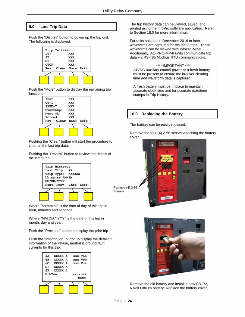
9.0 Last Trip Data
Push the “Display” button to power up the trip unit. The following is displayed:
Push the “More” button to display the remaining trip functions:
Pushing the “Clear” button will start the procedure to clear all the last trip data. Pushing the “Review” button to review the details of the latest trip:
Where “hh:mm:ss” is the time of day of this trip in hour, minutes and seconds. Where “MM:DD:YYYY” is the date of this trip in month, day and year. Push the “Previous” button to display the prior trip. Push the “Information” button to display the detailed information of the Phase, neutral & ground fault currents for this trip:
The trip history data can be viewed, saved, and printed using the InfoPro software application. Refer to Section 18.0 for more information. For units shipped in December 2016 or later, waveforms are captured for the last 8 trips. These waveforms can be viewed with InfoPro-MP-II. Additionally, AC-PRO-MP-II units communicate trip data via RS-485 Modbus RTU communications.
10.0 Replacing the Battery
The battery can be easily replaced. Remove the four (4) 2-56 screws attaching the battery cover.
Remove the old battery and install a new CR-P2, 6 Volt Lithium battery. Replace the battery cover.
**** IMPORTANT **** 24VDC auxiliary control power or a fresh battery must be present to ensure the breaker clearing time and waveform data is captured. A fresh battery must be in place to maintain accurate clock time and for accurate date/time stamps in Trip History.
Trip Tallies:
LT: XXX
ST: XXX
GF: XXX
QTGF: XXX
Rev Clear More Exit
Trip History:
Last Trip: #X
Trip Type: XXXXXX
hh:mm:ss AM/PM
MM/DD/YYYY
Next Prev Info Exit
Remove (4) 2-56 Screws
Inst: XXX
QT-I: XXX
SAFE-T: XXX
OverTemp: XXX
Neut OL: XXX
Forced: XXX
Rev Clear Back Exit
Inst: XXX
QT-I: XXX
SAFE-T: XXX
OverTemp: XXX
Sluggish: XXX
Neut OL: XXX
Rev Clear Back Exit
ϕA: XXXXX A xxx Vab
ϕB: XXXXX A xxx Vbc
ϕC: XXXXX A xxx Vca
N: XXXXX A
GF: XXXXX A
BrkTme xx.x ms
Back
ϕA: XXXXX A
ϕB: XXXXX A
ϕC: XXXXX A
N: XXXXX A
GF: XXXXX A
BrkTme Back

AC-PRO-MP® & AC-PRO-MP-II® Instruction Manual www.utilityrelay.com
P a g e 25
11.0 Self-Test Feature
The AC-PRO-MP and AC-PRO-MP-II continually perform self tests in the background. If an internal problem is detected, the “Self Test OK” LED is turned off. The internal self tests include:
• Watch dog timer
• Memory check sum
• Memory access error
• Low battery voltage
• Actuator connected
• Setting problem
12.0 Primary & Secondary Injection
12.1 Primary Injection Testing A primary injection test is recommended as the final test of the AC-PRO-MP or MP-II. This tests the complete system. If Ground Fault with the “T” option (residual) is used, GF must be temporarily turned off when single phase testing the other trip functions with a primary injection test set.
12.2 Secondary Injection Testing
The AC-PRO-MP secondary injection test set provides a quick and easy way to test the AC-PRO-MP and AC-PRO-MP-II trip units. The test set performs a true test of each Phase and can also test the Ground Fault function. For units shipped prior to December 2016: The test set harness plugs into a port on the left side of the trip unit. For units shipped in December 2016 and later: The test set harness plugs into a port on the front of the trip unit. The same test set can be used for all AC-PRO-MP and MP-II trip units. If you do not have a test set harness for trip units that have a front test port, contact Utility Relay Company. Refer to the MP Test Set Instruction Manual for testing instructions and information. For the latest version, visit: http://www.utilityrelay.com/Side_Bar/Instruction_Manuals.html
Side Secondary injection test port (units shipped prior to December 2016)
Secondary injection test set
Front Secondary injection test port (units shipped December 2016 or later)

Utility Relay Company
P a g e 26
13.0 DINF Instantaneous Trip
Some Masterpact MP breakers have a DINF Instantaneous (DINF-I) feature. The DINF-I trip function is only enabled for a short time while the breaker is closing. After the breaker is fully closed and latched, the DINF-I trip function is disabled by the DINF micro-switch. The DINF-I function is controlled with a micro-switch and inertial mass. They are located in the lower control unit as shown in Section 3.3. The connection to the AC-PRO-MP or MP-II trip unit is via connector “A” as shown in in Section 2.2. Not all Masterpact MP breakers are equipped with the DINF micro-switch and, therefore, the DINF-I trip functison is never active. The DINF-I Pick-Up settings are fixed depend on the CT rating as shown below.
CT Rating (Amp)
DINF-I Pick-Up (Amp)
200 2200
250 2700
320 3400
400 4300
500 5400
600 6500
630 6800
800 8600
1000 10,800
1200 12,900
1250 12,900
1600 16,700
2000 20,800
2500 26,900
3000 32,300
3200 19,200
4000 24,000
5000 30,000
6000 36,000
6300 37,800
The DINF-I Pick-Up setting is not adjustable and is also not shown on the OLED display. If the breaker does NOT have a DINF cable, leave the DINF jumper in place. See Section 3.5. Without the DINF jumper, DINF Instantaneous will always be on.

AC-PRO-MP® & AC-PRO-MP-II® Instruction Manual www.utilityrelay.com
P a g e 27
FV, ALR, Ic1 and Ic2 Wiring
14.0 FV Segregated Trip Relay
The FV Segregated Trip relay is a latching relay that is latched when a trip event occurs that is programmed to operate this relay. None or one or more of the following trip events can be programed to latch this relay: Long Time Short Time Instantaneous Ground Fault QUICK-TRIP Instantaneous QUICK-TRIP Ground Fault Over Temperature SLUGGISH BREAKER If the FV Segregated trip relay is latched by a programmed trip event, it will stay latched until the next time the “Display” button is pushed. The operator then has the option to un-latch the relay as shown below:
The FV Segregated Trip Relay requires 24Vdc external power to operate. The FV Segregated trip relay contact is normally open and is brought out to terminals V1 & V2 as shown in the wiring diagram on Page 8 as well as above.
15.0 ALR Pre-Trip Alarm Relay
The ALR Pre-Trip alarm relay signals the fact that the breaker current is greater than 105% of the Long Time Pick-Up setting. This indicates that a Long Time overload trip is in process. When the breaker current drops below 105% of the Long Time Pick-Up setting or a trip occurs, the relay is de-energized and the contact opens. The ALR Pre-Trip alarm relay contact is normally open and is brought out to terminals LR1 & LR2 as shown in the wiring diagram on Page 8 as well as above.
16.0 Ic1 & Ic2 Load Monitoring Relays
If the STR 58U version is selected, the load monitoring relays Ic1 and Ic2 are active. These are independent relays that can be used for load sheading or alarms. These relays have independent pick-up and time delay settings as shown in the TCC in Section 21.6. Once energized, the relays stay energized until the breaker trips or for 10 seconds after the breaker current drops below the pick-up setting. The Ic1 relay contact is normally open and is brought out to terminal R1. The Ic2 relay contact is also normally open and is brought out to terminal R2. Both relays share the “C” common output as shown in the wiring diagram on Page 8 as well as above.
Unlatch FV Segregated
Trip Relay?
No Yes

Utility Relay Company
P a g e 28
17.0 Communications
Creating a complete power monitoring and communications system for a low voltage power distribution system is easy with AC-PRO-MP-II. The standard AC-PRO-MP-II trip unit communicates using industry standard Modbus RTU protocol through a single shielded twisted pair wire connected to the RS485 port. A number of trip units can be daisy-chained together to simplify installation. AC-PRO-MP-II communications features and information:
• Currents, 3-phase • Review and change all settings (“Changing
settings over Comm” user setting must be enabled at trip unit).
• Voltages, 3-phase • KW, total • KWHr, total • KVA, total • KVAHr, total • Power Factor data • Breaker position status (open or closed) • Trip unit alarms and status information • Sluggish-Breaker indication • QUICK-TRIP ON /OFF status • Trip unit time and date • Trip unit Information: serial number, firmware
revision. • Forced trip (“Forced trip over Comm” user setting
must be enabled at trip unit). • Trip history data for the last 8 trips
o Trip counts o Trip type (reason for trip) o Trip dates & timestamps o Trip currents & voltages o Breaker clearing times
A host PC running HMI software with Modbus device drivers collects information from the trip units. The driver interrogates each trip unit individually and reports that information back to the host PC applications on a continual basis. Additional trip units can be added to the system by simply providing the new trip unit’s ADDRESS to the HMI software. AC-PRO-MP-II trip units are compatible with the Modbus RTU communication protocol supplied with most HMI systems. Note: 24VDC control power is required for communications.
17.1 Communications Components
An AC-PRO-MP-II Modbus Communications system consists of the following hardware components:
1. AC-PRO-MP-II trip unit and breaker retrofit components.
2. Host PC (supplied by others). 3. Cabling topology (supplied by others).
Additional components to consider include:
1. OPC software with Modbus device drivers (supplied by others).
2. Modbus RTU/Ethernet converter (supplied by others).
3. Human-Machine Interface (HMI) System (supplied by others). These systems are used to view trip unit information graphically and often contain their own compatible Modbus Driver.
17.2 Communications Wiring
All AC-PRO-MP-II trip units are furnished with quick-disconnect communications cable assemblies. The cable assembly features a heavy-duty twist-lock connector and a terminal block, which mounts inside the switchgear. The purpose of the terminal block is to provide a connection location for the twisted pair wire as it is daisy-chained from cell to cell in a switchgear lineup. This enables any individual communicating AC-PRO-MP-II (mounted on a circuit breaker) to be removed without disrupting communications between the other communicating AC-PRO-MP-II trip units.
17.3 System Components & Computer Hardware
AC-PRO-MP-II communicates over the RS485 interface at 9600 or 19200 Baud, with 8 data bits, 1 stop bit and no parity using the Modbus RTU communications protocol.
17.4 Ethernet With the addition of an RS485 to Ethernet Converter an existing Local Area Network (LAN) can be used to carry data between trip units and the PC. Converters are widely available from a variety of industrial manufacturers. RS485 to Ethernet Converters are designed to be compatible with a TCP/IP network environment and typically connect to a LAN using standard 10Base-T modular CAT-5 cabling. These converters offer a relatively inexpensive means of connecting to a LAN.
17.5 Modbus Communications Register Map The AC-PRO-MP-II Modbus Communications Register Map is included in a separate document. This document can be found at the web page below: http://www.utilityrelay.com/Side_Bar/Instruction_Manuals.html
17.6 Communications Settings
Refer to Section 4.1 for information about Communications settings.
AC-PRO-MP® & AC-PRO-MP-II® Instruction Manual www.utilityrelay.com
P a g e 29
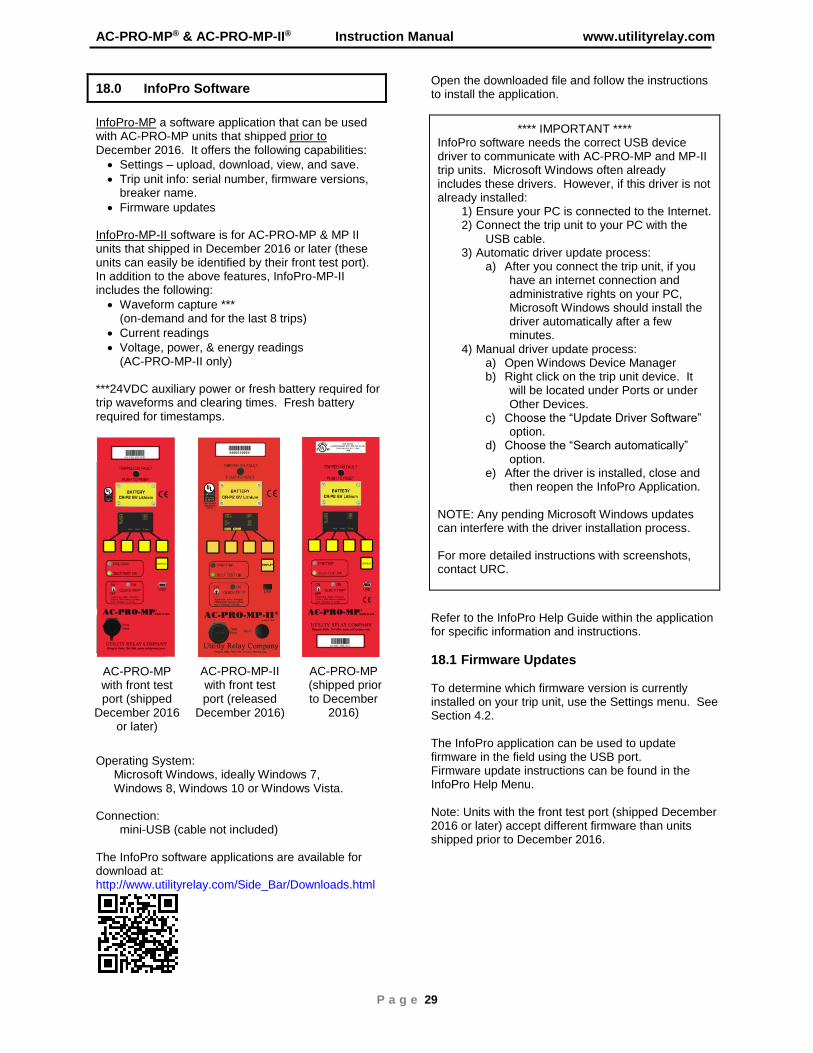
18.0 InfoPro Software
InfoPro-MP a software application that can be used with AC-PRO-MP units that shipped prior to December 2016. It offers the following capabilities:
• Settings – upload, download, view, and save.
• Trip unit info: serial number, firmware versions, breaker name.
• Firmware updates InfoPro-MP-II software is for AC-PRO-MP & MP II units that shipped in December 2016 or later (these units can easily be identified by their front test port). In addition to the above features, InfoPro-MP-II includes the following:
• Waveform capture *** (on-demand and for the last 8 trips)
• Current readings
• Voltage, power, & energy readings (AC-PRO-MP-II only)
***24VDC auxiliary power or fresh battery required for trip waveforms and clearing times. Fresh battery required for timestamps.
Operating System: Microsoft Windows, ideally Windows 7, Windows 8, Windows 10 or Windows Vista. Connection: mini-USB (cable not included) The InfoPro software applications are available for download at: http://www.utilityrelay.com/Side_Bar/Downloads.html
Open the downloaded file and follow the instructions to install the application.
**** IMPORTANT **** InfoPro software needs the correct USB device driver to communicate with AC-PRO-MP and MP-II trip units. Microsoft Windows often already includes these drivers. However, if this driver is not already installed:
1) Ensure your PC is connected to the Internet. 2) Connect the trip unit to your PC with the
USB cable. 3) Automatic driver update process:
a) After you connect the trip unit, if you have an internet connection and administrative rights on your PC, Microsoft Windows should install the driver automatically after a few minutes.
4) Manual driver update process: a) Open Windows Device Manager b) Right click on the trip unit device. It
will be located under Ports or under Other Devices.
c) Choose the “Update Driver Software” option.
d) Choose the “Search automatically” option.
e) After the driver is installed, close and then reopen the InfoPro Application.
NOTE: Any pending Microsoft Windows updates can interfere with the driver installation process. For more detailed instructions with screenshots, contact URC.
Refer to the InfoPro Help Guide within the application for specific information and instructions.
18.1 Firmware Updates To determine which firmware version is currently installed on your trip unit, use the Settings menu. See Section 4.2. The InfoPro application can be used to update firmware in the field using the USB port. Firmware update instructions can be found in the InfoPro Help Menu. Note: Units with the front test port (shipped December 2016 or later) accept different firmware than units shipped prior to December 2016.
AC-PRO-MP with front test port (shipped
December 2016 or later)
AC-PRO-MP (shipped prior to December
2016)
AC-PRO-MP-II with front test port (released
December 2016)

Utility Relay Company
P a g e 30
InfoPro-MP-II Waveform Tab Screenshot
19.0 Warranty
The AC-PRO-MP & AC-PRO-MP-II have a conditional 2-year warranty. Please view the warranty page at the beginning of this manual for the full details. Visit www.UtilityRelay.com or call 888-289-2864 for the latest information.
20.0 Environmental Ratings
Ambient Temperature: Trip Unit Electronics: -4°F (-20°C) to 158°F (70°C) OLED Display: -22°F (-30°C) to 158°F (70°C) Battery: -4°F (-20°C) to 140°F (60°C) Humidity: 95% non-condensing Conformal Coating: Acrylic conformal coating, HumiSeal type 1A33 UL Component File #E105698 Enclosure: 14 Gauge, type 304 stainless steel Battery: Panasonic CR-P2 6 Volt, 1400 mAh Lithium Non-Rechargeable
21.0 Time Current Curves
The pages to follow include the Time Current Curves for the AC-PRO-MP and AC-PRO-MP-II
AC-PRO-MP® & AC-PRO-MP-II® Instruction Manual www.utilityrelay.com
P a g e 31
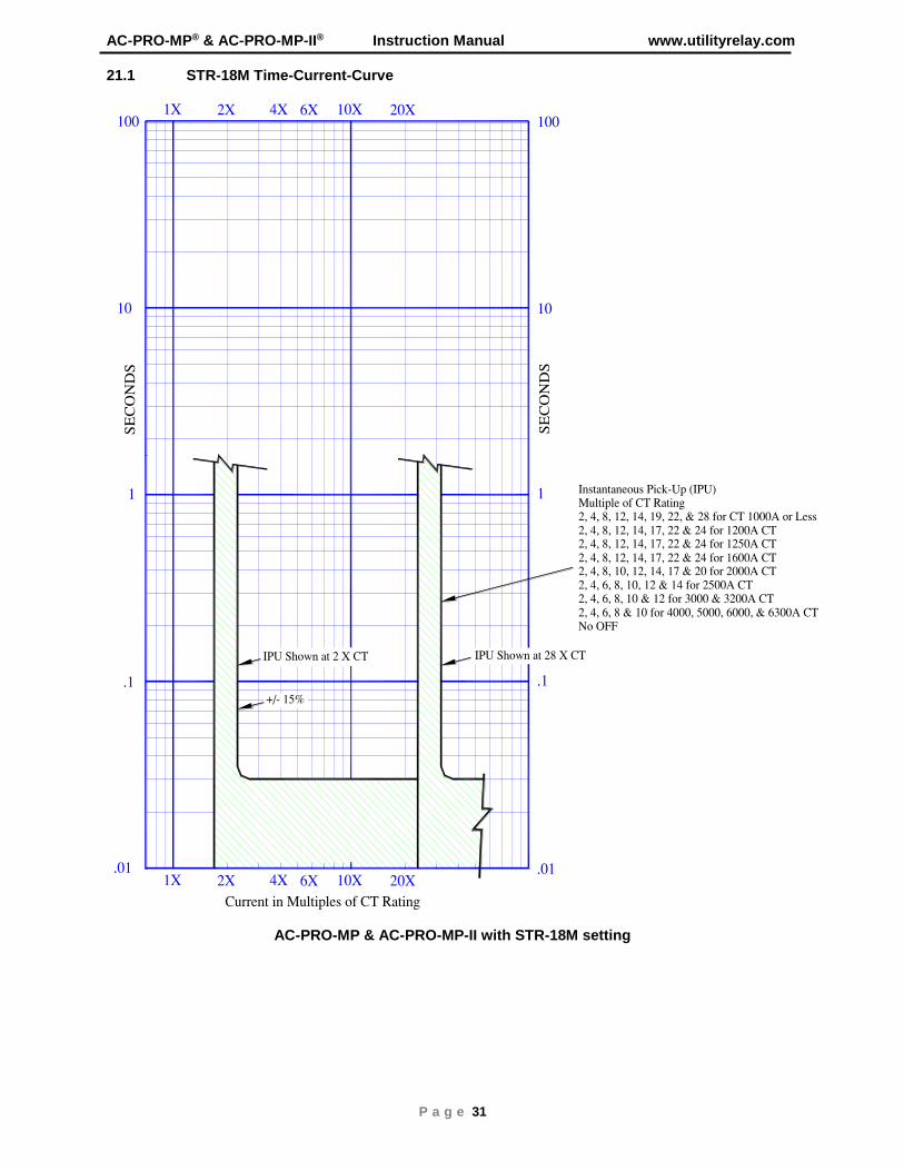
21.1 STR-18M Time-Current-Curve
AC-PRO-MP & AC-PRO-MP-II with STR-18M setting
Utility Relay Company
P a g e 32
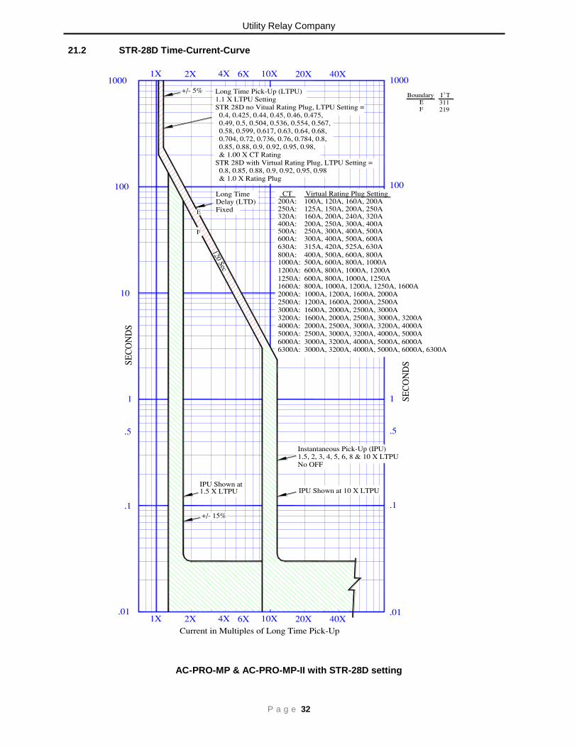
21.2 STR-28D Time-Current-Curve
AC-PRO-MP & AC-PRO-MP-II with STR-28D setting

AC-PRO-MP® & AC-PRO-MP-II® Instruction Manual www.utilityrelay.com
P a g e 33
21.3 STR-38S Time-Current-Curve
AC-PRO-MP & AC-PRO-MP-II with STR-38S setting

Utility Relay Company
P a g e 34
21.4 STR-58U Time-Current-Curve
AC-PRO-MP & AC-PRO-MP-II with STR-58U setting

AC-PRO-MP® & AC-PRO-MP-II® Instruction Manual www.utilityrelay.com
P a g e 35
21.5 STR-38S & 58U Ground Fault Time-Current-Curve
AC-PRO-MP & AC-PRO-MP-II with STR-38S or STR-58U setting

Utility Relay Company
P a g e 36
21.6 STR-58U Load Monitoring Time-Current-Curve
AC-PRO-MP & AC-PRO-MP-II with STR-58U setting

AC-PRO-MP® & AC-PRO-MP-II® Instruction Manual www.utilityrelay.com
P a g e 37
21.7 QUICK-TRIP® Instantaneous Time-Current-Curve
AC-PRO-MP & AC-PRO-MP-II with STR-58U setting

Utility Relay Company
P a g e 38
21.8 QUICK-TRIP® Ground Fault Time-Current-Curve
AC-PRO-MP & AC-PRO-MP-II
AC-PRO-MP® & AC-PRO-MP-II® Instruction Manual www.utilityrelay.com
P a g e 39
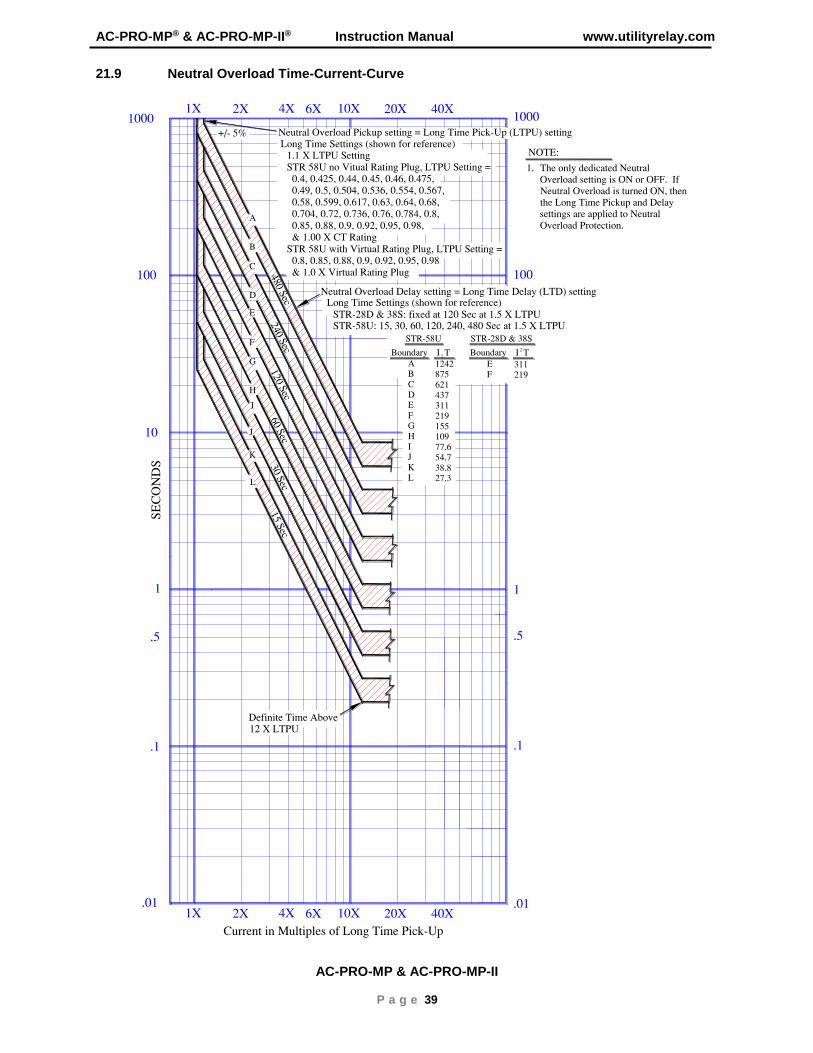
21.9 Neutral Overload Time-Current-Curve
AC-PRO-MP & AC-PRO-MP-II

This page left intentionally blank

This page left intentionally blank
