table of contents basic instrumentation -...
TRANSCRIPT
TABLE OF CONTENTS
Basic Instrumentation
Chapter 01 IntroduCtIon » Instruments Overview » Types of Display » Comparison » Modern Displays » Display / Flight Deck Integration » Line Replaceable Units
Chapter 02 pressure sensIng » Introduction » Pressure » Pressure Units » Measuring Pressure » Pressure Sources for Flight Instruments » Measurement Methods - Overview » Pitot Tubes » Static Ports » Combined Pressure Head » Source by Instrument » Errors » Summary

TABLE OF CONTENTS
Chapter 03 the altImeter » Introduction » The International Standard Atmosphere » Altimeter Calibration » Altimeter Units » Principle of Operation » Construction » Altimeter Errors » Temperature Error » Temperature Correction » Barometric Error » Memory Aids for Temperature and Barometric Errors » Orographic Effect » Time Lag » Blockages » Leaks » Altimeter Types » Altimeter Displays » Altitude Definitions

TABLE OF CONTENTS
Chapter 04 the VertICal speed IndICator (VsI) » Introduction » VSI Units » Principle of Operation » Metering Unit » Errors » Time Lag » The Instantaneous VSI (IVSI) » Blockages and Leaks » Using the VSI and IVSI » VSI Displays » Inertial Rate of Climb
Chapter 05 the aIr speed IndICator (asI) » Units of Distance and Speed » Airspeed » Pressure Sensing » The Simple ASI » Calibration » Compressibility Error » Density Error » Speed Definitions » Blockages » Leaks » Displays » ASI Colour Coding and Important Speeds » Coloured Lines and V Speeds » The TAS Scale
TABLE OF CONTENTS
Chapter 06 the maChmeter » Introduction » The Local Speed of Sound » Mach Number » Measuring Mach Number » The Machmeter » Instrument Errors » Blockages » Pitot Blockage » Static Blockage » Leaks » Machmeter Displays » CAS, TAS and Mach Number Relationship » Effect of Altitude Change in the ISA » Effect of Altitude Change in an Isothermal Layer » Effect of Altitude Change in an Inversion » EAS and CAS Relationship » Effect of Temperature Change at Same Flight Level
Chapter 07 temperature » Introduction » Temperature » Methods of Measurement » Electrical - Thermocouple » Radiation » Probes » Ram Rise and Total Air Temperature » Ram Rise and SAT Calculations » Temperature Measurement Errors » Summary
TABLE OF CONTENTS
Chapter 08 angle of attaCk » Introduction » Vane » Probe » Summary
Chapter 09 the aIr data Computer
» Introduction » Architecture » ADC Inputs » ADC Outputs » Parameters » Systems Which Receive ADC Outputs » System Redundancy » Integration » Advantages of an ADC » Summary

TABLE OF CONTENTS
Chapter 10 terrestrIal magnetIsm » Introduction » Terrestrial Magnetism » Field Components » Long Term Changes » Short Term Changes » Magnetic Direction » Magnetic Variation » The Limits of Direction » Gross Error Checking Direction and Variation Calculations » Variation over Time » Extracting Variation » Isogonals » Summary
Chapter 11 the dIreCt IndICatIng Compass » Introduction » Basic Compass Construction » Interpreting the Compass » Compass Errors » Compass Magnet Assembly » Effect of Manoeuvre - General » Effect of Manoeuvre - Acceleration » Effect of Manoeuvre - Turning » Compass Serviceability » Summary

TABLE OF CONTENTS
Chapter 12 aIrCraft magnetIsm & deVIatIon » Introduction » Compass Deviation » The Cause of Compass Deviation » The Effect of Aircraft Magnetism » Compensating for Compass Deviation » The Requirement for Compass Swing » Converting Between Compass and True » Gross Error Checking » Summary
Chapter 13 gyro BasICs » Introduction » Rigidity » Mounting a Gyroscope » Degrees of Freedom » Applications for 2 Gimbal Gyros » Displacement Gyros » Wander » Real Wander » Gimbal Limitations » Precession » The Consequences of Precession » Instrument Applications for Precession » Gyro Power Sources » Pneumatic Gyro Power » Electric Gyro Power » Typical RPMs » Supply Redundancy » Other Types of Gyros » Summary
TABLE OF CONTENTS
Chapter 14 the dIreCtIonal gyro (dg) » Introduction » Principle of Operation » Display » Erection - Pneumatic » The Erection Process » Behaviour During Flight » Erection - Electric » Errors » The Latitude Nut (LN) » Transport Drift (TD) » Summary
Chapter 15 the remote IndICatIng Compass » Introduction » The Flux Valve » The Stator » The Slaving Circuit » Controls and Annunciation » Errors » Summary » Appendix 1: The Flux Valve

TABLE OF CONTENTS
Chapter 16 the attItude IndICator » Introduction » Principle of Operation » Display » Erection - Pneumatic » Rate of Erection » Instrument Errors » Electrically Driven AI Errors » Summary
Chapter 17 the turn IndICator & turn CoordInator » Introduction » The Turn Indicator » Turn Indicator Principle of Operation » The Turn Indicator Display » Calculating the Radius of Turn » Turn Indicator Errors » Turn Indicator Limits » The Turn Coordinator » Turn Coordinator Principle of Operation » Turn Coordinator Display » Turn Coordinator Errors » The Balance Indicator » Correcting Imbalance » Integration with Turn Indicator or Coordinator » Effect of Imbalance on Turn Radius » Summary

TABLE OF CONTENTS
Advanced Instrumentation and Systems
Chapter 01 InertIal naVIgatIon systems (Ins) » Introduction » Inertial Navigation » Inertial System Technology » Accelerometers » Purpose of the INS Platform » Rate Integrating Gyros » Initial Alignment » The Effect of Latitude During Alignment » Position Input During Alignment » Inertial System Corrections » Coriolis Effect » Schuler Oscillation » Inertial System Power Supplies and Reversion » Summary » Annex 1: Types of Inertial System » Delco Carousel IV

TABLE OF CONTENTS
Chapter 02 InertIal referenCe system (Irs) » Introduction » INS Versus IRS » Ring Laser Gyros » Strap Down Arrangement » Strap Down Alignment » Strap Down Operation » Schuler Oscillations » Summary » Annex 1:B737 (300-400-500) IRS
Chapter 03 the radIo altImeter » Introduction » Principle of Operation » System Calibration and Accuracy » Radio Altimeter Displays » EFIS Radio Altimeter Displays » Summary

TABLE OF CONTENTS
Chapter 04 the flIght management system (fms) » Introduction » FMS Control Display Unit » FMC Databases » FMS Set-up » FMS Programming and Operational Procedures » The IDENT Page » Position Initialisation (POS INIT) Page » The Route (RTE) Page » The Departure and Arrival (DEP/ARR) Page » The Performance Initialisation (PERF INIT) Page » The Take-off Reference (TAKEOFF REF) Page » Using the FMS En-route » Glossary of Terms

TABLE OF CONTENTS
Chapter 05 eleCtronIC flIght InformatIon system (efIs) » Introduction » The EFIS System » The Symbol Generators » The EFIS Control Panel » Ambient Light Sensor Unit » The EADI or PFD » Attitude Indicator » Auto Flight System Mode Annunciation » Flight Director (FD) Display » Glide Slope (G/S) and Localiser Deviation Indicators » Radio Altitude (RA) and Decision Height » Pitch Limit Indicators » The EHSI or Navigation Display (ND) » MAP Mode » Full Rose Display Modes » Full VOR/ILS Mode » Full NAV Mode » Expanded Rose Displays » PLAN Mode » EFIS Failure Annunciation
Chapter 06 Computers In aVIatIon » Introduction » Analogue Computers » Digital Computers » The Binary Number System » Decimal to Binary Number Conversion » Binary System Logic » Hexadecimal (HEX) Number System » The Components of a Digital Computer
TABLE OF CONTENTS
Chapter 07 the head-up dIsplay » Introduction » The HUD Principle of Operation » The Display Guidance Computer (DGC) » The Display Controller » The Display » Warning Displays » Future Development in HUD Systems
Chapter 08 future aIr naVIgatIon systems (fans) » Introduction » ACARS » CPDLC » FANS-1/A » The Logon » Automatic Dependent Surveillance » FANS 2/B
Chapter 09 flIght dIreCtor system » Introduction » The Flight Director » Flight Director System (FDS) Design. » AFDS Mode Control Panel (MCP). » Flight Mode Annunciator (FMA) » Common Lateral Modes

TABLE OF CONTENTS
Chapter 10 the autopIlot » Introduction » Types of Autopilot System » The Inner or Closed Loop Control System. » Outer Loop Systems » Servomotor (Actuator) Control » Autopilot Engagement » Flight Path (Command) Modes » Flight Mode Selection » Lateral (Roll) Flight Modes » Lateral Navigation Mode LNAV » Approach (APP) Mode » Pitch (Vertical) Modes » Vertical Navigation (V NAV) Mode » Altitude Hold (ALT HLD)
Chapter 11 auto-throttle » Introduction » Auto-throttle Control » Auto-throttle Operation » Thrust Mode Annunciator (TMA) Panel
Chapter 12 automatIC landIng system » Introduction » Requirements for an Autoland System » Fail Passive (Fail Soft) Autoland System » Fail Operational (Fail Active) Autoland System » Alert Height » Low Visibility Categories

TABLE OF CONTENTS
Chapter 13 yaw dampers » Introduction » Yaw Damper System
Chapter 14 flIght warnIng system (fws) » Introduction » Level of Alerts » Notification of Alert » Visual Alerts » Aural Alerts » Sensory Alerts
Chapter 15 fws aerodynamIC warnIngs » Introduction » Altitude Alert System » Overspeed Warning » Stall Warning
Chapter 16 traffIC alert and aVoIdanCe system (tCas) » Introduction » TCAS I » TCAS II » TCAS II System Operation » TCAS II Aircraft Equipment » TCAS Advisories and Displays » TCAS Inhibits and Operating Restrictions » TCAS Mode Control » Crew response to a TA or RA » TCAS III » TCAS RA Standard Phraseology

TABLE OF CONTENTS
Chapter 17 ground proxImIty warnIng systems » Introduction » GPWS System » GPWS Modes, Warnings and Alerts » GPWS Modes » Enhanced Ground Proximity Warning System » Terrain Clearance Floor » EU OPS Requirements
Chapter 18 flIght data reCorder » Introduction » The Digital Flight Data Recorder » Aircraft Condition Monitoring System (ACMS) » Aircraft Integrated Data System (AIDS) » Cockpit Voice Recorder (CVR) » The CVR System
Chapter 19 engIne Instruments » Gas Turbine Engines » Performance Indicators » Engine Condition Indicators » Turbo-prop Engines » Measuring Engine RPM » Measuring Pressure » Measuring Temperature » Measuring Fuel Contents » Fuel Flow Meters
TABLE OF CONTENTS
Chapter 20 eleCtronIC CentralIsed aIrCraft monItorIng » Introduction to ECAM » Engine Warning (E/W) Display Unit. » The System /Status (S/S) Display Unit. » ECAM Control Panel (ECP) » Example System Operation
Chapter 21 engIne Instrument and Crew alertIng system » Introduction to EICAS » The EICAS System » EICAS Display » Operational Mode » Status Mode » Maintenance Mode » Crew Alerting Messages » Warnings (Level A) » Cautions (Level B) » Advisories (Level C) » EICAS System Failures

CHAPTER 6: THE MACHMETER
Introduction
The Local Speed of Sound
Mach Number
Measuring Mach Number
The Machmeter
Instrument Errors
Blockages
Pitot Blockage
Static Blockage
Leaks
Machmeter Displays
CAS, TAS and Mach Number Relationship
Effect of Altitude Change in the ISA
Effect of Altitude Change in an Isothermal Layer
Effect of Altitude Change in an Inversion
EAS and CAS Relationship
Effect of Temperature Change at Same Flight Level

Issue 1 6.2
The Machmeter
Introduction
Mach number gives you an indication of the air’s compressibility. This is important because as the aeroplane’s TAS approaches the local speed of sound of the air, the air will experience compression and if speed is further increased, shockwaves will form. These shockwaves occur first just after Mcrit, a Mach number well below that for the local speed of sound and will increase in size and severity as the speed increases further.
Many commercial aeroplanes today are not designed to fly at the speeds where shockwaves will form. Some transport aeroplanes however can fly at speeds just into the transonic region and to do this have been designed to manage the problems of stability and control associated with the formation of shockwaves. However in both cases, the aeroplane will have a limiting maximum Mach number (MMO) which must not be exceeded. A machmeter is therefore essential for all aeroplanes that fly at faster speeds.
The Local Speed of Sound
We will see shortly that Mach number is affected by the local speed of sound (LSS). The speed that sound propagates through air depends on its temperature. The LSS being faster in warmer air and slowing as air temperature reduces.
A formula to calculate the LSS in knots is given below:
LSS = 39 √Temperature (in Kelvin)
06
Issue 1 6.3
Basic Instrumentation The Machmeter
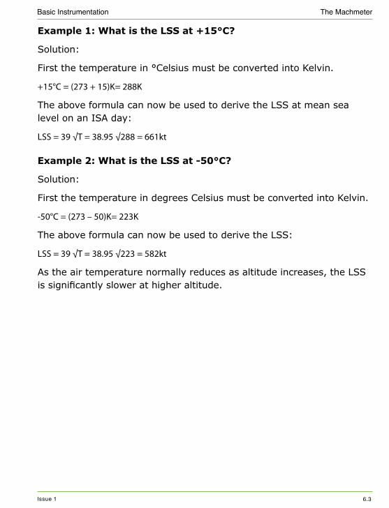
Example 1: What is the LSS at +15°C?
Solution:
First the temperature in °Celsius must be converted into Kelvin.
+15°C = (273 + 15)K= 288K
The above formula can now be used to derive the LSS at mean sea level on an ISA day:
LSS = 39 √T = 38.95 √288 = 661kt
Example 2: What is the LSS at -50°C?
Solution:
First the temperature in degrees Celsius must be converted into Kelvin.
-50°C = (273 – 50)K= 223K
The above formula can now be used to derive the LSS:
LSS = 39 √T = 38.95 √223 = 582kt
As the air temperature normally reduces as altitude increases, the LSS is significantly slower at higher altitude.

Issue 1 6.4
Basic Instrumentation The Machmeter
Mach Number
Mach number (M) is a ratio of the TAS to the LSS and therefore has no units. It is determined by the formula:
M = TAS
LSS
Example 3:What is the Mach number at a TAS of 450kts if the LSS is 580kt?
Solution:
M = TAS/LSS = 450/580 = 0.776 (to 3 significant Figures)
Example 4: What is the LSS given a TAS of 480kts and M0.80?
Solution:
M = TAS/LSS
LSS = TAS/M = 480/0.8 = 600kt

Issue 1 6.5
Basic Instrumentation The Machmeter
Measuring Mach Number
The machmeter is a cleverly designed pressure instrument. This is because it indicates Mach number without directly measuring TAS or temperature (to determine LSS). As the inclusion of the machmeter in pressure instruments infers, it does so by comparing the ratio of pressures, and more specifically the ratio of dynamic to static pressure.
Where M α √ dynamic pressure
static pressure
Mach number (M) is the ratio of TAS to the LSS and is determined by the formula:
M = TAS
LSS
However as the machmeter is a pressure instrument it actually determines Mach number by ratioing dynamic to static pressure.
M α √ dynamic pressure
static pressure
Recall from the gas laws that PV/T is constant and therefore T α PV. Since V α 1/ρ then T α P/ρ. In this context the pressure is static pressure (S) so we can see that T α S/ρ.

Issue 1 6.6
Basic Instrumentation The Machmeter
The Machmeter
The machmeter measures the ratio of the dynamic to static pressure to gain a calibrated indication of Mach number. To ratio the dynamic to static pressure, the machmeter therefore contains an airspeed capsule that expands with dynamic pressure and a sealed altitude capsule that reacts to the static pressure in the case.
figure 6.1 The machmeter
When airspeed increases, the airspeed capsule expands and the airspeed link is pushed out. This rotates the main shaft which moves the ratio arm in direction A, up and out of Figure 6.1 (shown in red). Whenever the ratio arm moves out of the diagram, the ranging arm is pushed out of the diagram which causes the pointer to indicate an increase in Mach number (shown in blue).

Issue 1 6.7
Basic Instrumentation The Machmeter
When altitude increases, the altitude capsule expands. The pin attached to the capsule moves in direction B, pushing the ratio arm down and out of the diagram (shown by green arrows). This again moves the ranging arm out of the diagram and the pointer shows an increase in Mach number (shown in blue).
Conversely, a reduction in airspeed or altitude, results in the ranging arm moving in directions C and D respectively. This means that the ranging arm, which is held against the ratio arm by a spring, moves into the diagram and the pointer shows a reduction in Mach number.
In summary, if either capsule expands the Mach number increases and if they contract the Mach number will decrease.

Issue 1 6.8
Basic Instrumentation The Machmeter
Instrument Errors
The machmeter only suffers from the pressure instrument errors of ;
JJ Instrument error.
JJ Manoeuvre induced error.
JJ Position error.
You may be wondering why the machmeter does not suffer from the combined errors of the airspeed indicator and altimeter, as it includes both an airspeed and altitude capsule. This is because any potential density (and compressibility) errors are cancelled out in the ratioing of the capsule movements which is central to the machmeter’s operation. In addition the machmeter does not suffer from barometric error, as there is no comparative reference pressure; or temperature error, as the static pressure is not calibrated to the ISA to give height.
Blockages
Like the airspeed indicator, the machmeter will also suffer from pitot and static blockages, which will work in the same sense as the airspeed indicator. This means that the memory aid ‘PudSod’ may again help you remember the descent situation, with the climb situation being the opposite.
In summary, PudSod stands for Pitot blocked machmeter under reads in the descent and Static blocked the machmeter will over read in the descent.
We will now look at a pitot and then static blockage.

Issue 1 6.9
Basic Instrumentation The Machmeter
Pitot Blockage
If the pitot line is blocked and the aeroplane descends (assumption at same CAS) then the static component in the capsule will remain the same. However the static pressure in the case will increase and be greater than the static component in the capsule, resulting in the airspeed capsule being over compressed. This will result in the ratio arm moving into the diagram in direction C (in error).
The increasing static pressure in the case will correctly compress the altitude capsule which will move the ratio arm in direction D. In a descent at a constant airspeed with no blockages of the pitot lines, the machmeter would have correctly shown the reduction in Mach number. However the pitot line blockage will result in the reduction in Mach number being too great and the machmeter under reads the correct value. This is shown in the diagram below:
figure 6.2 With a pitot blockage the machmeter under reads in descent

Issue 1 6.10
Basic Instrumentation The Machmeter
Conversely a blockage of the pitot line followed by the aeroplane climbing, would result in the airspeed capsule over expanding, due to the larger static component in the capsule. This would cause the machmeter to over read.
From a practical point of view the target mach number is being held but is incorrect. Therefore;
JJ In the climb, holding the same target mach number could result in the stall because the machmeter is over reading.
JJ In the descent, holding the same target mach number could result in an overspeed because the machmeter is under reading.

Issue 1 6.11
Basic Instrumentation The Machmeter
Static Blockage
If the static line is blocked and the aeroplane then descends, the static component in the case will remain the same. The altitude capsule will therefore not move when it should have been contracting. This should have moved the ratio arm into the diagram and shown a reduction in Mach number. Relatively therefore the Mach number is over reading.
figure 6.3 Static blockage
In addition, the static pressure component in the airspeed capsule will be increasing and no longer cancel out with the smaller static pressure blocked in the case. The airspeed capsule over expands, with the ratio arm moving in direction A in Figure 6.3.
For the reasons in the two paragraphs above the machmeter will over read.
Conversely in the climb, the static pressure trapped in the case would be too great and over compress both the altitude and airspeed capsules, causing it under read.

Issue 1 6.12
Basic Instrumentation The Machmeter
Leaks
The machmeter will suffer from leaks of the pitot and static lines. The errors caused will be the same in sense, as those of the airspeed indicator.
Pitot Line Leak
If there is a leak in the pitot line, some of the high pressure air in the pitot line will escape into the cabin. The pressure in the airspeed capsule will now be too low, resulting in the capsule not expanding enough, moving the ratio arm in direction C and the machmeter will under read.
figure 6.4 Static line leak
A leak in the static line will affect the static pressure in the case. The actual effect will depend on whether the cabin is pressurised or not.

Issue 1 6.13
Basic Instrumentation The Machmeter
In the case of a pressurised aeroplane, the higher cabin pressure will enter the static line, causing the pressure in the case to be too large. As a result the altitude and airspeed capsules will be too compressed, moving the ratio arm into the diagram in directions C and D respectively and the machmeter will under read.
figure 6.5 Static leak
In a unpressurised aeroplane the cabin pressure will be marginally lower, due to aerodynamic suction. This will cause a slight over read.

Issue 1 6.14
Basic Instrumentation The Machmeter
Machmeter Displays
Mach number derived from a machmeter on the flight deck, will either be presented on a combined mach airspeed indicator (MASI) or machmeter. On the MASI the mach number is read off a drum display as shown in below left. The machmeter as shown above, indicates mach number by a needle rotating over a mach number scale.
On more modern aeroplanes with an ADC and digital displays, Mach number will be presented as a digital number, such as shown below right, at the bottom of the airspeed tape.
80
60
MACH
KNOTS
0
100
120140160180
200
250
300
3503508
52 8
7
300
280
260
220
200
2432
250
.595
15
REF
Current Mach
figure 6.6 MASI and digital speed tape
Issue 1 6.15
Basic Instrumentation The Machmeter
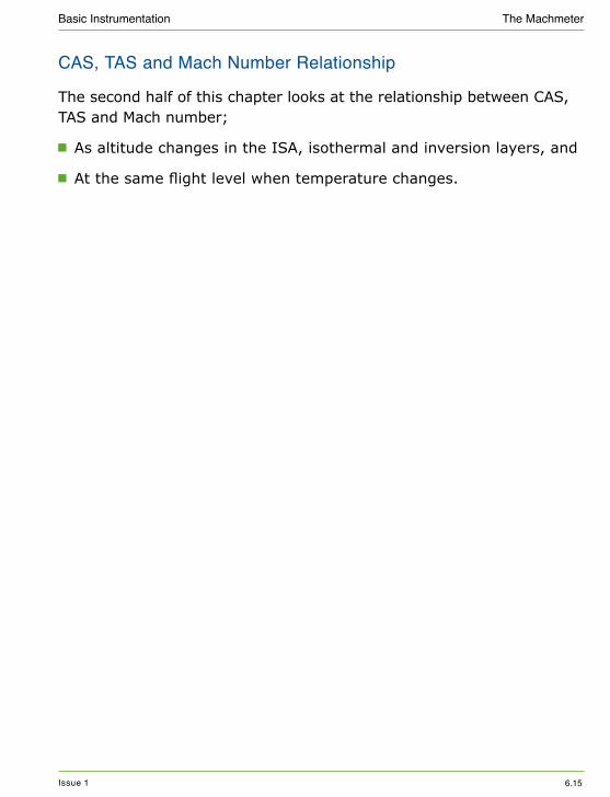
CAS, TAS and Mach Number Relationship
The second half of this chapter looks at the relationship between CAS, TAS and Mach number;
JJ As altitude changes in the ISA, isothermal and inversion layers, and
JJ At the same flight level when temperature changes.

Issue 1 6.16
Basic Instrumentation The Machmeter
Effect of Altitude Change in the ISA
As we climb and descend either at a constant CAS or Mach number, we need to understand the effect this has on the other speeds.
The easiest way of introducing the normal relationship between these speeds and altitude, is to consider what would happen if we did climb at a constant TAS.
Figure 6.7 shows a graph with altitude as the vertical axis, altitude increasing as we move up the diagram. The horizontal axis represents speed (CAS, TAS or M), with speed increasing to the right.
ClimbDescent
(high)
Alti
tude
(low)
(slow) Speed (fast)
C T M
figure 6.7 Altitude effect
A climb or descent at a constant TAS, is therefore represented as a vertical green line because the TAS is not getting faster or slower as altitude changes.

Issue 1 6.17
Basic Instrumentation The Machmeter
We will first consider what will happen to the Mach number as we climb. In ISA, it gets colder as you climb higher and therefore the LSS will decrease. As the aeroplane climbs at the same TAS, the reduction in the LSS will cause the Mach number (M) to increase.
M = TAS (same)
LSS
The red line labelled ‘M’ is therefore moving to the right (increasing M) as the climb progresses. Conversely in a descent at a constant TAS the air gets warmer causing the LSS to increase and the Mach number to decrease. The red ‘M’ line therefore moves to the left (slower) as you move down the diagram.
The relationship between TAS and CAS can be thought of simply in that as an aeroplane climbs at the same real speed (TAS) the air gets less dense and hence the dynamic pressure and CAS reduce (blue line moves left) . You can also see this in the below equation.
CAS2 ∝ 1/2 ρ TAS
In the descent the increasing air density causes the dynamic pressure and CAS to increase and therefore the blue line moves to the right as you move down the diagram.

Issue 1 6.18
Basic Instrumentation The Machmeter
Many pilots think of this normal ISA relationship as ‘Chicken Tikka Masala’. This helps you remember the order of CAS, TAS and M from left to right. Some people hold their hand in front of them as a visual aid.
figure 6.8 Using your hand as a memory aid
Issue 1 6.19
Basic Instrumentation The Machmeter
Climbing and Descending at Constant CAS
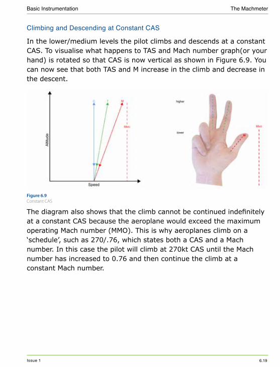
In the lower/medium levels the pilot climbs and descends at a constant CAS. To visualise what happens to TAS and Mach number graph(or your hand) is rotated so that CAS is now vertical as shown in Figure 6.9. You can now see that both TAS and M increase in the climb and decrease in the descent.
figure 6.9 Constant CAS
The diagram also shows that the climb cannot be continued indefinitely at a constant CAS because the aeroplane would exceed the maximum operating Mach number (MMO). This is why aeroplanes climb on a ‘schedule’, such as 270/.76, which states both a CAS and a Mach number. In this case the pilot will climb at 270kt CAS until the Mach number has increased to 0.76 and then continue the climb at a constant Mach number.
Issue 1 6.20
Basic Instrumentation The Machmeter
Climbing and Descending at a Constant Mach Number
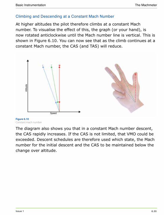
At higher altitudes the pilot therefore climbs at a constant Mach number. To visualise the effect of this, the graph (or your hand), is now rotated anticlockwise until the Mach number line is vertical. This is shown in Figure 6.10. You can now see that as the climb continues at a constant Mach number, the CAS (and TAS) will reduce.
figure 6.10 Constant mach number
The diagram also shows you that in a constant Mach number descent, the CAS rapidly increases. If the CAS is not limited, that VMO could be exceeded. Descent schedules are therefore used which state, the Mach number for the initial descent and the CAS to be maintained below the change over altitude.
Issue 1 6.21
Basic Instrumentation The Machmeter
Effect of Altitude Change in an Isothermal Layer
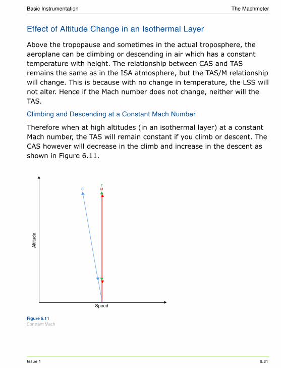
Above the tropopause and sometimes in the actual troposphere, the aeroplane can be climbing or descending in air which has a constant temperature with height. The relationship between CAS and TAS remains the same as in the ISA atmosphere, but the TAS/M relationship will change. This is because with no change in temperature, the LSS will not alter. Hence if the Mach number does not change, neither will the TAS.
Climbing and Descending at a Constant Mach Number
Therefore when at high altitudes (in an isothermal layer) at a constant Mach number, the TAS will remain constant if you climb or descent. The CAS however will decrease in the climb and increase in the descent as shown in Figure 6.11.
Altit
ude
Speed
C MT
figure 6.11 Constant Mach

Issue 1 6.22
Basic Instrumentation The Machmeter
Climbing and Descending at a Constant CAS
In a rarer isothermal layer at lower/medium levels the pilot will be climbing or descending at a constant CAS. Figure 6.12 shows that the TAS and Mach number will both increase in the climb and decrease in the descent.
Altit
ude
Speed
C MT
figure 6.12 Constant CAS

Issue 1 6.23
Basic Instrumentation The Machmeter
Effect of Altitude Change in an Inversion
Occasionally at altitudes used by commercial aeroplanes, inversions occur in the atmosphere and for a narrow layer the air temperature increases as altitude increases.
In the climb the LSS will increase as air temperature increases and therefore for the same TAS the M will reduce.
M = TAS (same)
LSS
However the CAS/TAS relationship remains the same in sense (ie the CAS remains to the left or slower than TAS). This is because air density is always dominated by the pressure rather than the temperature, so the air density always reduces as altitude increases.
The actual magnitude of the variation between CAS and TAS will however alter between the three atmosphere types. The variation will be greatest in an inversion because the density will be reducing because both the pressure is reducing and the temperature increasing. It would be least in the ISA atmosphere when the air density change caused by the pressure decrease is reduced because of the affect of the air temperature is reducing.
Alti
tude
Speed
Alti
tude
Speed
C M T C M T
figure 6.13 Constant CAS and M
Issue 1 6.24
Basic Instrumentation The Machmeter
Figure 6.13 shows that when climbing through an inversion at a constant CAS the M and TAS will increase. However if climbing at a constant M the CAS will reduce and the TAS increase.
Memory Aid
The normal ISA relationship as ‘Chicken Tikka Masala’ now inverts to ‘Chicken Masala Tikka’ for the inversion. This helps you remember the order has now changed to CAS, M and then TAS from left to right.
EAS and CAS Relationship
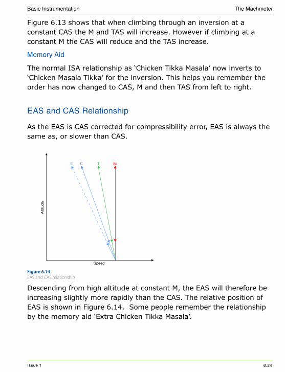
As the EAS is CAS corrected for compressibility error, EAS is always the same as, or slower than CAS.
Alti
tude
Speed
CE T M
figure 6.14 EAS and CAS relationship
Descending from high altitude at constant M, the EAS will therefore be increasing slightly more rapidly than the CAS. The relative position of EAS is shown in Figure 6.14. Some people remember the relationship by the memory aid ‘Extra Chicken Tikka Masala’.

Issue 1 6.25
Basic Instrumentation The Machmeter
Effect of Temperature Change at the Same Flight Level
The final part of this chapter looks at the relationship between CAS, TAS and Mach number when flying at a constant flight level into warmer or colder air.
It is important to realise that although the true altitude will be changing slightly, the pressure altitude is not. This type of problem is therefore not answered using ‘Chicken Tikka Masala’ method earlier in this chapter.
LSSTASSame M=Constant flight level0.78M
TAS 455ktCAS 263kt
TAS 465ktCAS 263kt
CAS2 ∝ ½ TAS2 Same
0.78M
Colder air Warmer air
∂
figure 6.15 Change in temperature at same flight level
Figure 6.15 shows an aeroplane flying at a constant flight level into a warmer air mass. Due to the increase in temperature and therefore faster LSS, to maintain the same M the TAS must have increased. However the CAS (and CAS2 ) as shown will have remained the same. This is because the effect of the increase in air temperature, increases the TAS2 in the same proportion that it reduces the air density.
In summary, if temperature changes when flying at the same flight level at a constant M, the CAS will remain the same. By the same reasoning, if flying at the same CAS, the M will not change.

Issue 1 6.26
Basic Instrumentation The Machmeter
The TAS will change however, in response to the change in air density. The TAS will increase flying into warmer air and reduce flying into colder air. Some students remember this with ‘Temperature up TAS up’, and ‘Temperature down TAS down’.