ta202a – manufacturing processes group …home.iitk.ac.in/~jrkumar/download/sample project...
TRANSCRIPT
Rice Transplanting Machine
TA202A – Manufacturing Processes
Group Number: 44 Group Members:
Anirban Manna -13113 Ayush Poddar - 13186 Harshit Lathi - 13295 Pankaj Kumar Verma - 13461 Rachit Agarwal - 13524 Shashank Bhushan - 13645 Sourabh Vaid - 13765 Sunil Kumar - 13723
Guide Name: Mr. Mahesh Kumar
Table of Content 1. Abstract ................................................................................................................................ 12. Introduction ....................................................................................................................... 23. Design ..................................................................................................................................... 3
3.1. Planting Unit3.2. Designing of Tray3.3. Power Transmission System
4. Appendix ............................................................................................................................. 64.1. MATLAB Simulations4.2. Isometric Drawing of Full Assembly and Sub-Assemblies 4.3. Isometric Drawing of Planting Unit’s Parts4.4. Isometric Drawing of Tray’s Parts4.5. Isometric Drawing of Wheel’s Parts4.6. Isometric Drawing of With-worth Mechanism’s Parts 4.7. Isometric Drawing of Pulling Mechanism’s Parts4.8. Isometric Drawing and Calculations of Gears4.9. Isometric Drawing of Miscellaneous Parts
4.10. Cost Analysis
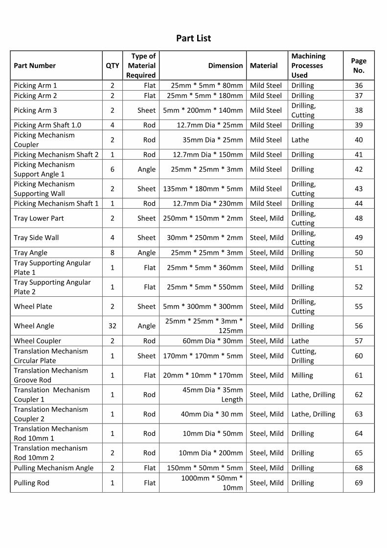
Part List
Part Number QTY Type of
Material Required
Dimension Material Machining Processes Used
Page No.
Picking Arm 1 2 Flat 25mm * 5mm * 80mm Mild Steel Drilling 36 Picking Arm 2 2 Flat 25mm * 5mm * 180mm Mild Steel Drilling 37
Picking Arm 3 2 Sheet 5mm * 200mm * 140mm Mild Steel Drilling, Cutting 38
Picking Arm Shaft 1.0 4 Rod 12.7mm Dia * 25mm Mild Steel Drilling 39 Picking Mechanism Coupler 2 Rod 35mm Dia * 25mm Mild Steel Lathe 40
Picking Mechanism Shaft 2 1 Rod 12.7mm Dia * 150mm Mild Steel Drilling 41 Picking Mechanism Support Angle 1 6 Angle 25mm * 25mm * 3mm Mild Steel Drilling 42
Picking Mechanism Supporting Wall 2 Sheet 135mm * 180mm * 5mm Mild Steel Drilling,
Cutting 43
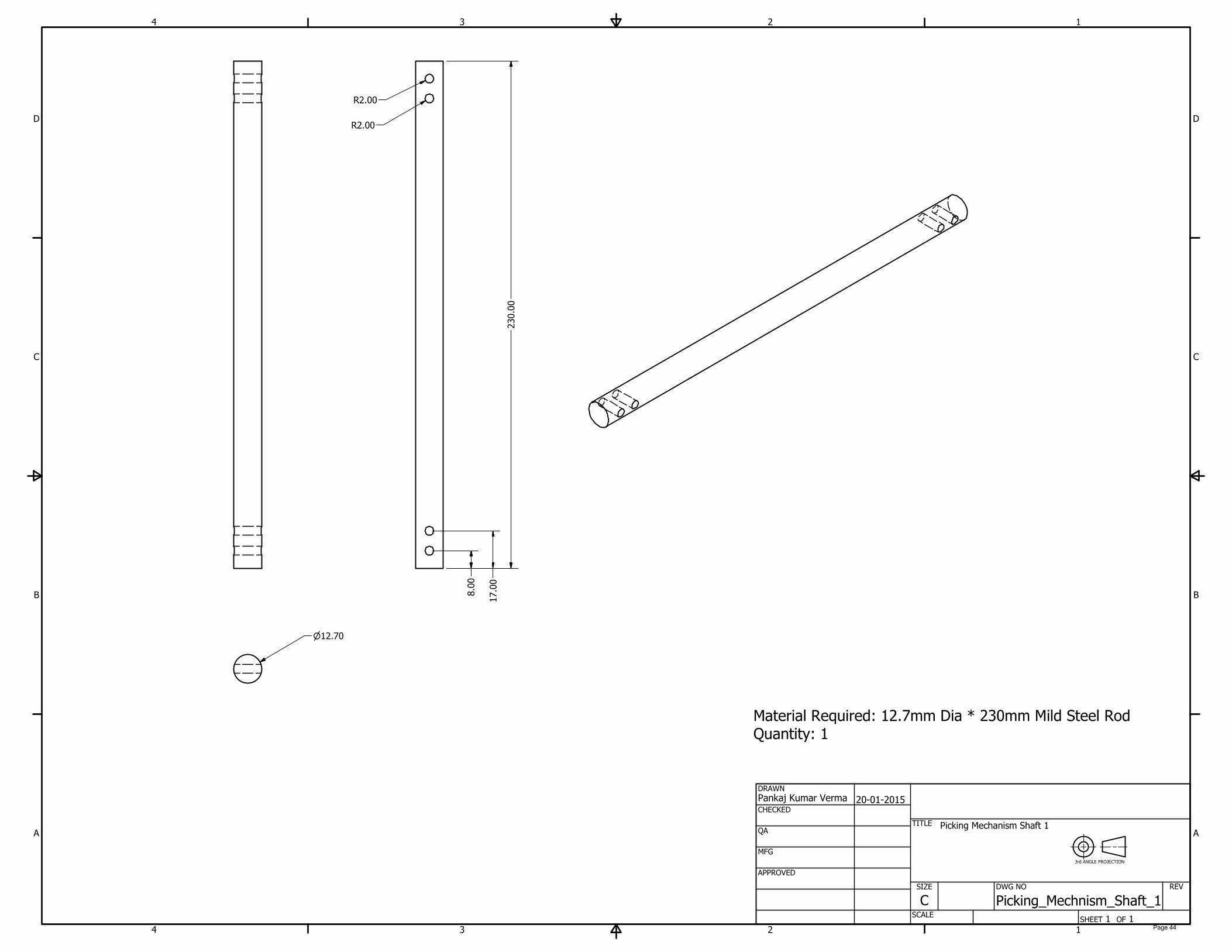
Picking Mechanism Shaft 1 1 Rod 12.7mm Dia * 230mm Mild Steel Drilling 44
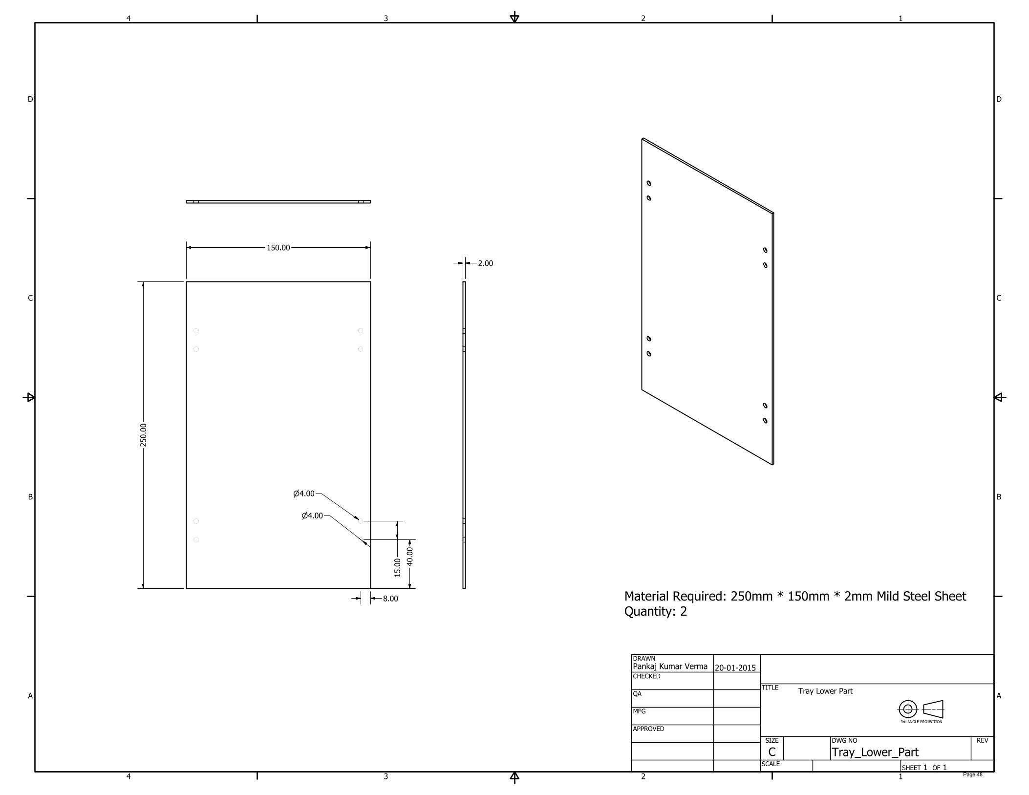
Tray Lower Part 2 Sheet 250mm * 150mm * 2mm Steel, Mild Drilling, Cutting 48
Tray Side Wall 4 Sheet 30mm * 250mm * 2mm Steel, Mild Drilling, Cutting 49
Tray Angle 8 Angle 25mm * 25mm * 3mm Steel, Mild Drilling 50 Tray Supporting Angular Plate 1 1 Flat 25mm * 5mm * 360mm Steel, Mild Drilling 51
Tray Supporting Angular Plate 2 1 Flat 25mm * 5mm * 550mm Steel, Mild Drilling 52
Wheel Plate 2 Sheet 5mm * 300mm * 300mm Steel, Mild Drilling, Cutting 55
Wheel Angle 32 Angle 25mm * 25mm * 3mm * 125mm Steel, Mild Drilling 56
Wheel Coupler 2 Rod 60mm Dia * 30mm Steel, Mild Lathe 57 Translation Mechanism Circular Plate 1 Sheet 170mm * 170mm * 5mm Steel, Mild Cutting,
Drilling 60
Translation Mechanism Groove Rod 1 Flat 20mm * 10mm * 170mm Steel, Mild Milling 61
Translation Mechanism Coupler 1 1 Rod 45mm Dia * 35mm
Length Steel, Mild Lathe, Drilling 62
Translation Mechanism Coupler 2 1 Rod 40mm Dia * 30 mm Steel, Mild Lathe, Drilling 63
Translation Mechanism Rod 10mm 1 1 Rod 10mm Dia * 50mm Steel, Mild Drilling 64
Translation mechanism Rod 10mm 2 2 Rod 10mm Dia * 200mm Steel, Mild Drilling 65
Pulling Mechanism Angle 2 Flat 150mm * 50mm * 5mm Steel, Mild Drilling 68
Pulling Rod 1 Flat 1000mm * 50mm * 10mm Steel, Mild Drilling 69

Pulling Mechanism Shaft 1 Rod 12.7mm Dia * 60 mm Length Steel, Mild Drilling 70
Pulling shaft 2 1 Rod 12.7mm Dia * 200mm Length Steel, Mild Drilling 71
Spur Gear 1 1 Rod 30mm Dia * 35mm Length Steel, Mild Turing, Milling,
Drilling 74
Spur Gear 2 1 Rod 130mm Dia * 35mm Length Steel, Mild Turing, Milling,
Drilling 75
Base Plate 1 Sheet 900mm * 500mm * 5mm Steel, Mild Cutting 81 Bevel Gear Support 2 Flat 140mm * 50mm * 10mm Steel, Mild Drilling 82
Shaft 210 mm 1 Rod 12.7mm Dia * 210mm Length Steel, Mild Drilling 83
Plant Blocking Plate 1 Sheet 470mm * 50mm * 2mm Steel, Mild Drilling 84
Wheel Rod 1 Rod 12.7mm Dia * 420mm Length Steel, Mild Drilling 85
Shaft 200mm 1 Rod 12.7mm Dia * 200mm Length Steel, Mild Drilling 86
Support Angle Standard 10 Angle 50mm * 50mm * 6mm * 50mm Length Steel, Mild Cutting,
Drilling 87
Tray Power Transmission Support Bar 1 Flat 140mm * 25mm * 6mm Steel, Mild Drilling 88
Tray Support 2 Flat 25mm * 250mm * 10mm Steel, Mild Drilling 89
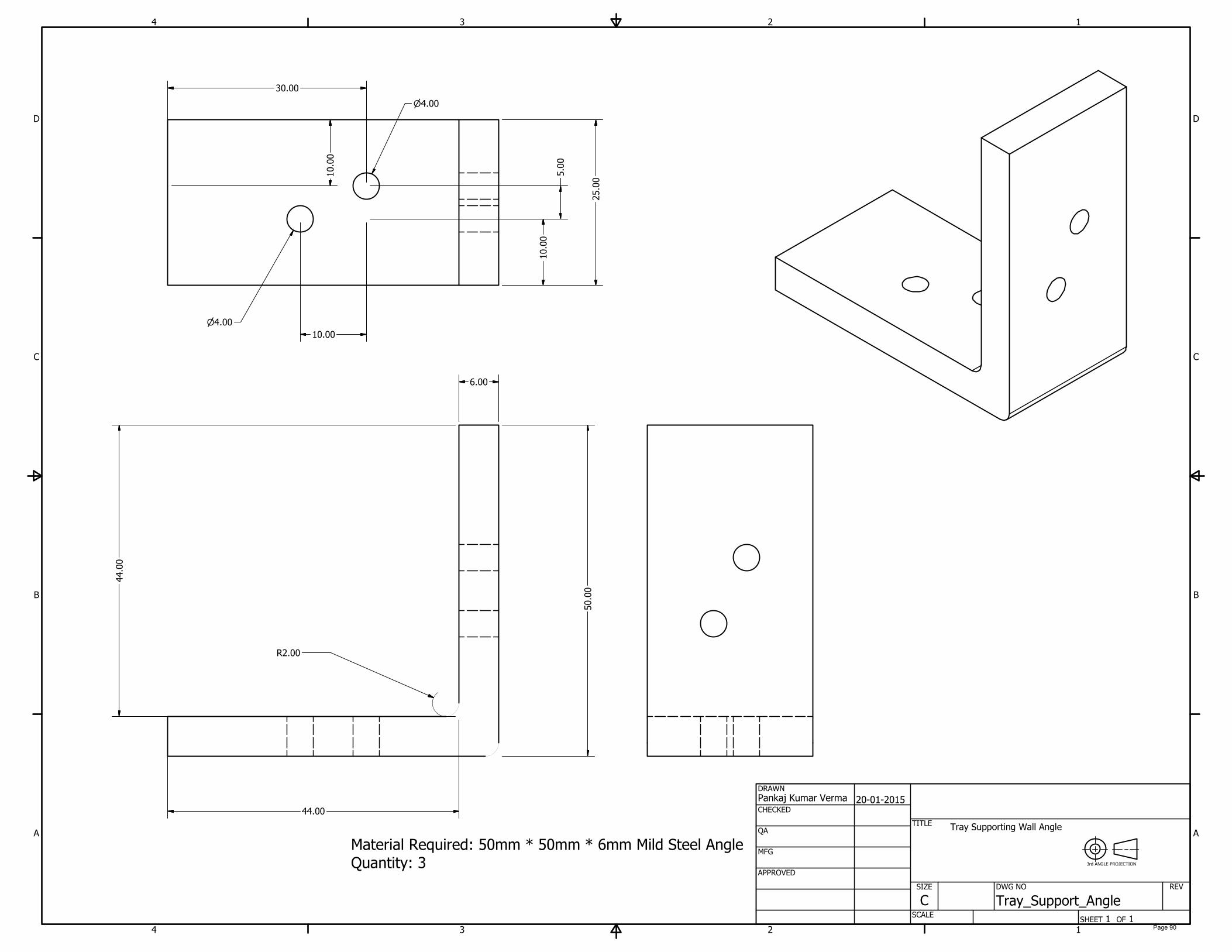
Tray Support Angle 3 Angle 50mm * 50mm * 6mm * 50mm Length Steel, Mild Drilling 90
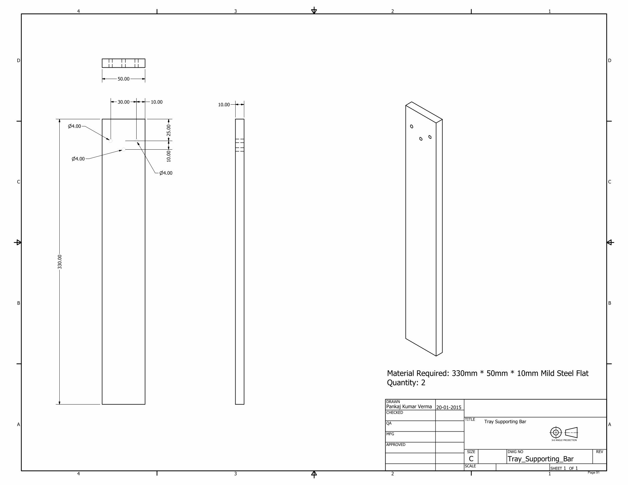
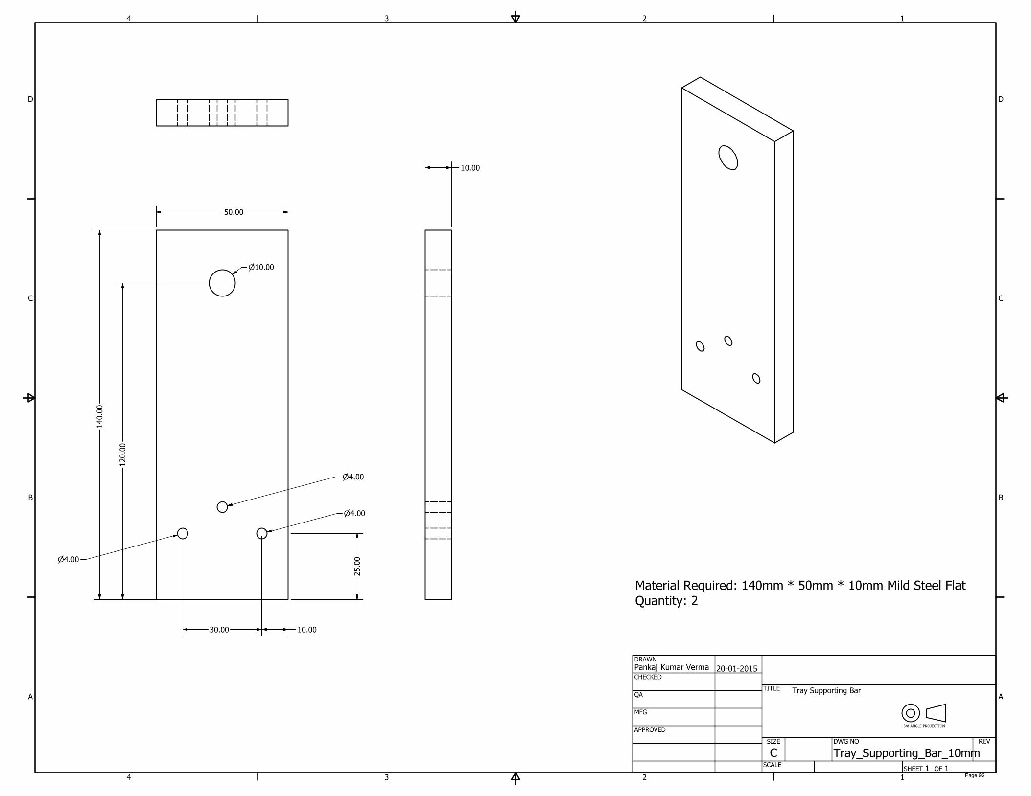
Tray Supporting Bar 2 Flat 50mm * 10mm * 330mm Steel, Mild Drilling 91 Tray Supporting Bar 10mm 2 Flat 140mm * 50mm * 10mm Steel, Mild Drilling 92
Wheel Support 4 Flat 140mm * 50mm * 10mm Steel, Mild Drilling 93

Abstract
Agriculture is the most important sector of the Indian economy. It is the most important source of employment for the majority of the work force in the country. A major population in India is engaged in agriculture. Among that highest percentage was in paddy sector. Rice is the major stable food of the country. Releasing of work force to sectors other than Agriculture is important to develop the country. To release the work force in paddy sector mechanization plays a big role. To feed growing population is a huge challenge. Mechanization of paddy sector will lead to higher productivity with releasing of work force to other sectors. The objective of this project is to design a paddy transplanting mechanism to transplant paddy seedlings by small scale farmers in the country.
Page 1

Introduction
Transplanting is one of the major process for establishment of paddy in India. In this method seed is sown in one place and seedlings after they have grown a little are transplanted to another. This is done in order to get higher yields and less weeding. Transplanting of rice is highly labour intensive and it may require 250-350 man-hours per hectares.
Seedling are prepared in nurseries where they grow for 15-20 days. After these seedling are been prepared, these are been transplanted manually by labour. The orientation of the labour at the time of transplanting is hazardous for their health. With manual transplantation the cost of production of rice also increases.
With the help of a Rice Transplanting Machine, the transplantation cost as well as time will decreases with increase in efficiency.
Page 2

Design
The Rice Transplanting machine’s most important mechanisms are for the planting unit, paddy seedling tray and Power transmission system and attachments.
Planting Unit
When designing the planting Mechanism following aspects were considered:
• Moving pathway • Speed of traveling • Plant catching mechanism • Depth of planting
Moving pathway
A four bar linkage mechanism was used to get the required measurements.
Figure 1: Planting Arm
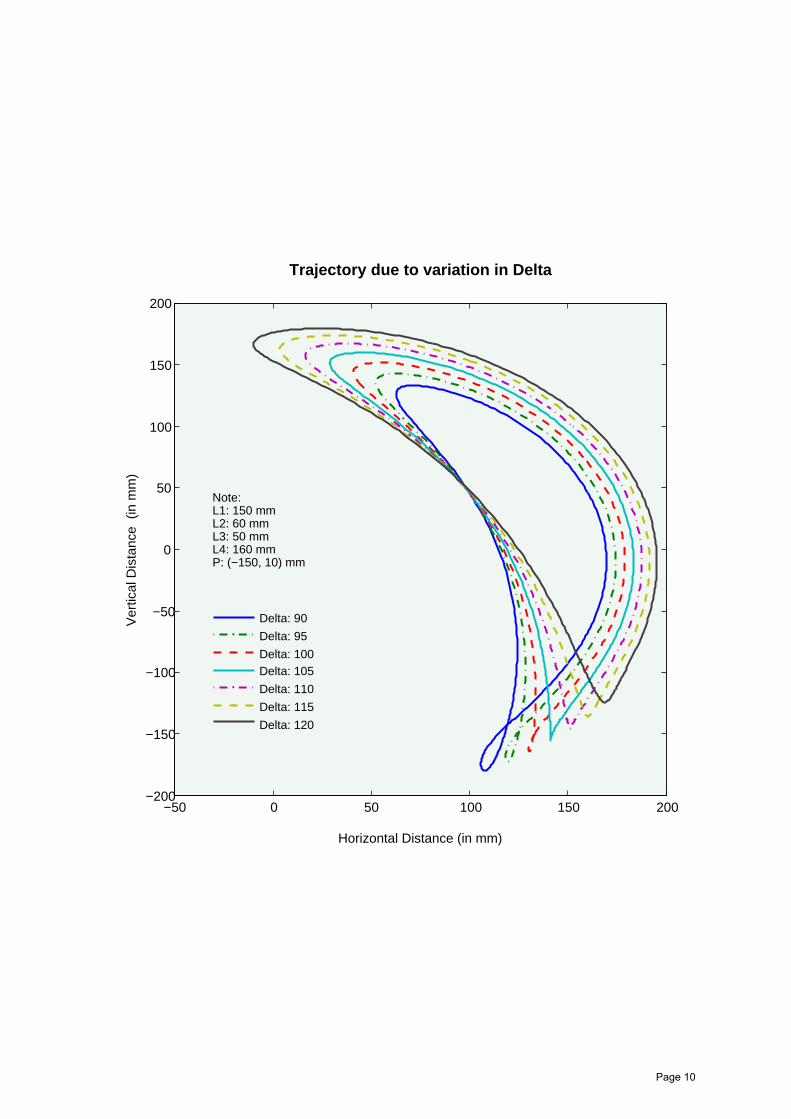
The trajectory of the planting unit depends on:
1. Point P 2. Length L1, L2, L3 and L4 3. Delta
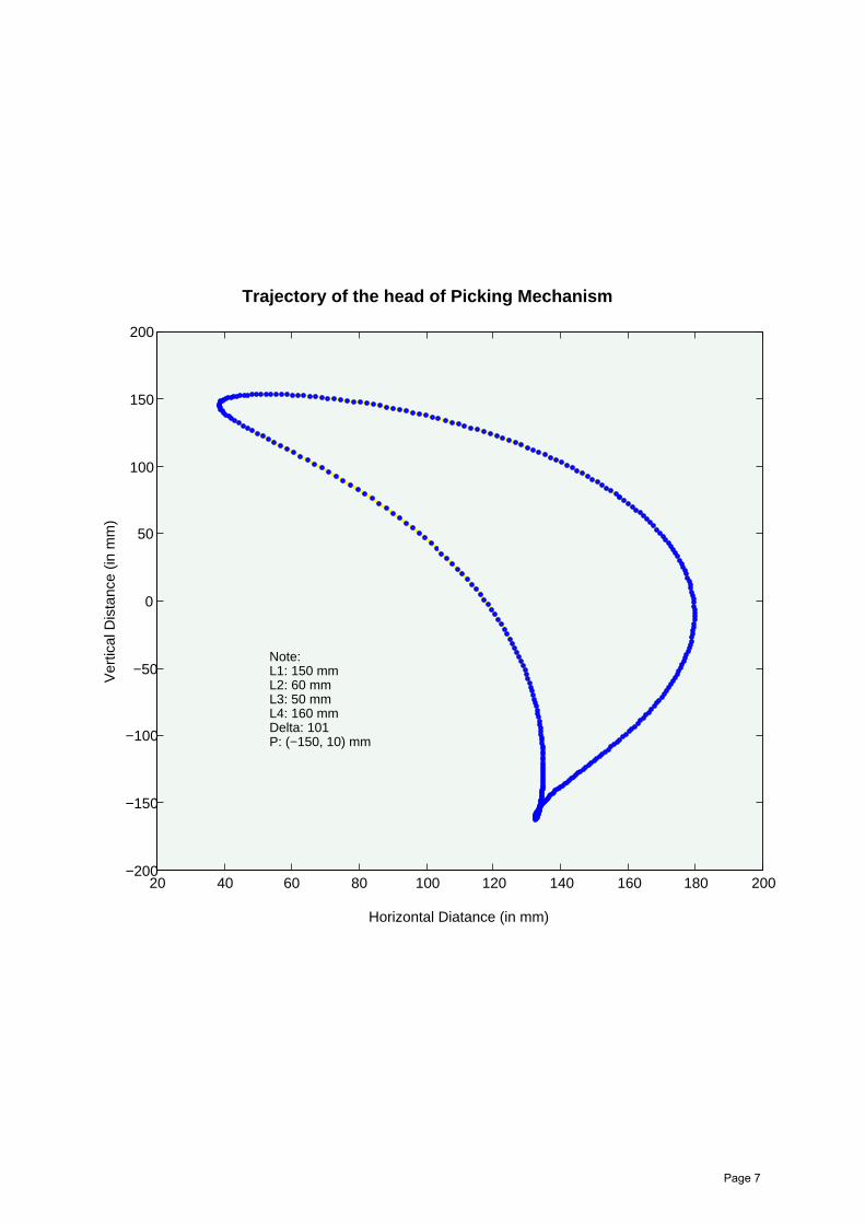
Theta is the variable which varies from 0 to 360 degree. The trajectory is plotted in MATLAB with all the variations of the above discussed variables. The optimised plot was chosen for which the values are:
Page 3
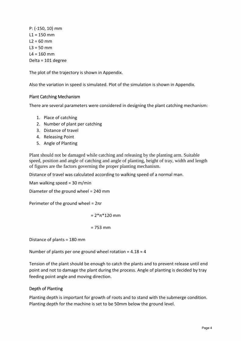
P: (-150, 10) mm L1 = 150 mm L2 = 60 mm L3 = 50 mm L4 = 160 mm Delta = 101 degree
The plot of the trajectory is shown in Appendix.
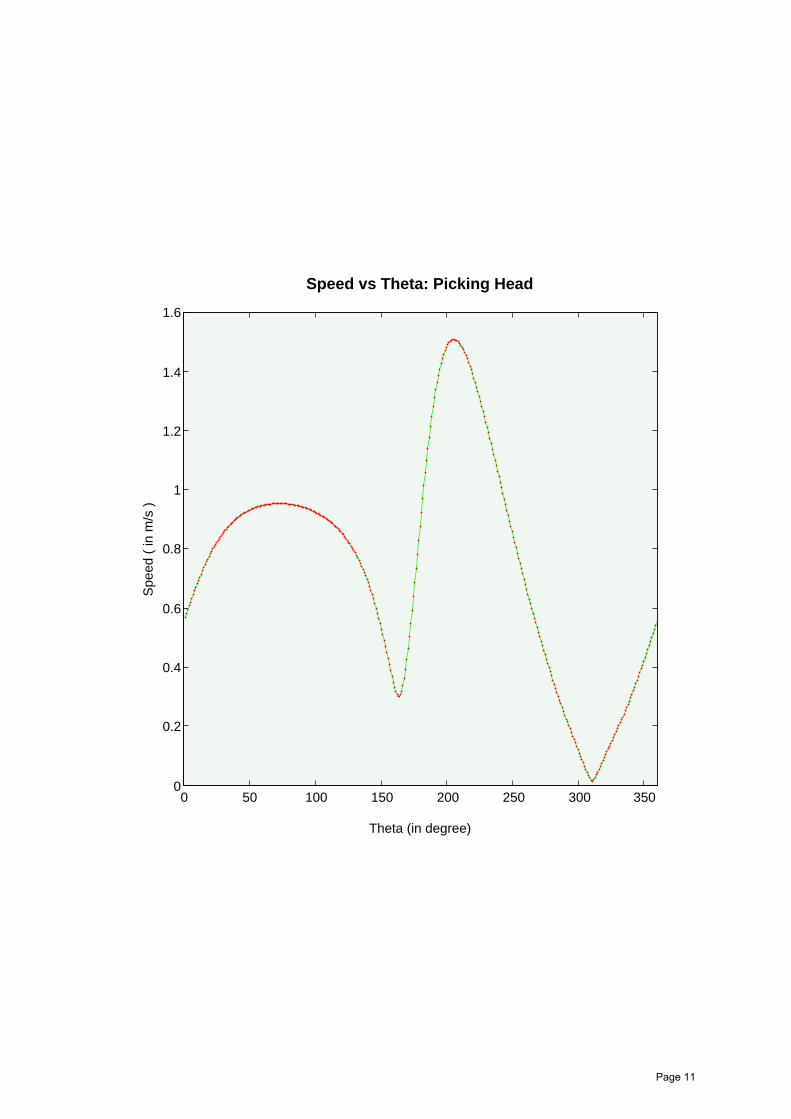
Also the variation in speed is simulated. Plot of the simulation is shown in Appendix.
Plant Catching Mechanism
There are several parameters were considered in designing the plant catching mechanism:
1. Place of catching 2. Number of plant per catching 3. Distance of travel 4. Releasing Point 5. Angle of Planting
Plant should not be damaged while catching and releasing by the planting arm. Suitable speed, position and angle of catching and angle of planting, height of tray, width and length of figures are the factors governing the proper planting mechanism.
Distance of travel was calculated according to walking speed of a normal man.
Man walking speed = 30 m/min
Diameter of the ground wheel = 240 mm
Perimeter of the ground wheel = 2πr
= 2*π*120 mm
= 753 mm
Distance of plants = 180 mm
Number of plants per one ground wheel rotation = 4.18 ≈ 4
Tension of the plant should be enough to catch the plants and to prevent release until end point and not to damage the plant during the process. Angle of planting is decided by tray feeding point angle and moving direction.
Depth of Planting
Planting depth is important for growth of roots and to stand with the submerge condition. Planting depth for the machine is set to be 50mm below the ground level.
Page 4
Designing of Tray
Tray is to carry the seed mat and to direct the plants to planting arm. Basic factors (width, length, angle, speed of movement) is considered in designing the tray mechanism. As two plant rows are planted at once, two trays are placed side by side for each planting hand. Movement of the tray per one planting of arm is decided by the volume taken away from the planting finger at a time. The length of the movement of tray is taken to be 5 mm.
To make constant feeding of the seed mat to the planting arm it should come down to the end of the try by gravity. Higher angle reduces energy requirement to feed the seed mat to transplanting arm while too much angle effect on falling down and compaction of nursery at the end of the tray making difficult to take out the plants from the nursery by transplanting arm. The final angle of the tray is 60°.
The design of the tray is shown in appendix.
Power Transmission system
All the power generation is achieved by wheel. Chain and sprocket mechanism is used to transmit power to the planting unit.
No of teeth of sprocket at wheel = 34
No of teeth of sprocket at planting mechanism = 9
No of plants planted per wheel rotation = 34/9 = 3.8
Tray has to move very slowly relative to the wheel. The gear ratio is 9:1.
Page 5
APPENDIX – 1
Plot of the trajectory of the planting fingers and the speed of the optimised mechanism
1. Optimised length and angle of the Mechanism2. Plot due to variation of length L33. Plot due to variation of length L44. Plot due to variation of angle delta5. Plot of the speed of the planting finger
Page 6
20 40 60 80 100 120 140 160 180 200−200
−150
−100
−50
0
50
100
150
200
Trajectory of the head of Picking Mechanism
Horizontal Diatance (in mm)
Ver
tical
Dis
tanc
e (in
mm
)
Note:L1: 150 mmL2: 60 mmL3: 50 mmL4: 160 mmDelta: 101P: (−150, 10) mm
Page 7

−20 0 20 40 60 80 100 120 140 160 180 200−200
−150
−100
−50
0
50
100
150
200
Trajectory due to variation of L3
Horizontal Distance (in mm)
Ver
tical
Dis
tanc
e (in
mm
)
L3: 45 mm
L3: 50 mm
L3: 55 mm
Note: L1: 150 mmL2: 60 mmL4: 160 mmDelta: 101P: (−150, 10) mm
Page 8
0 50 100 150 200 250
−200
−150
−100
−50
0
50
100
150
200
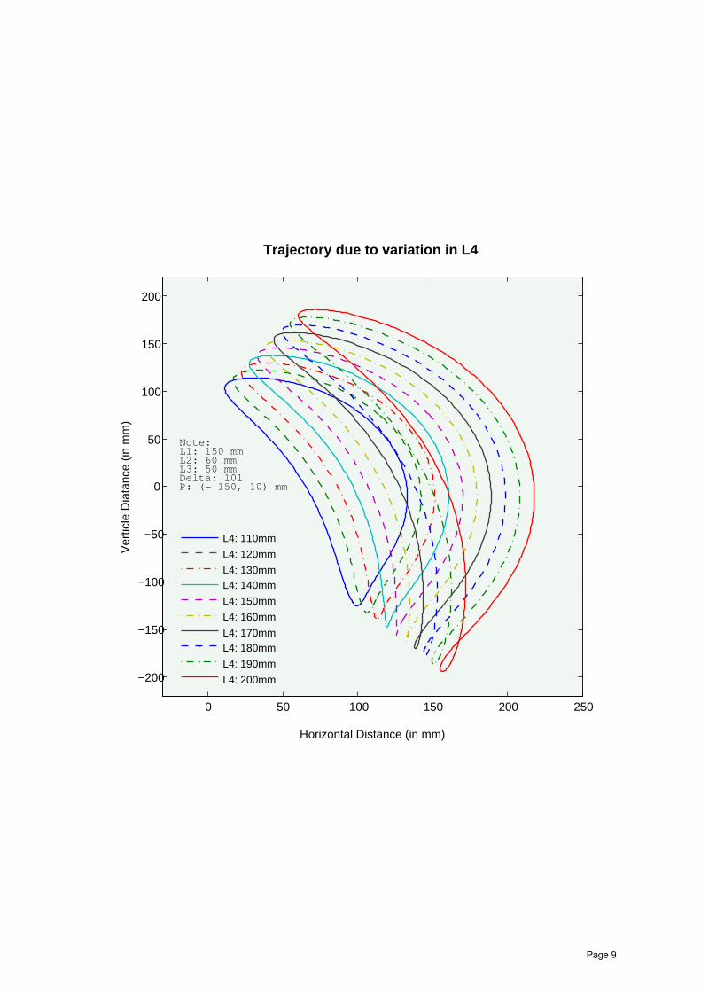
Trajectory due to variation in L4
Horizontal Distance (in mm)
Ver
ticle
Dia
tanc
e (in
mm
)
L4: 110mm
L4: 120mm
L4: 130mmL4: 140mm
L4: 150mm
L4: 160mm
L4: 170mmL4: 180mm
L4: 190mm
L4: 200mm
Note:L1: 150 mmL2: 60 mmL3: 50 mmDelta: 101P: (− 150, 10) mm
Page 9
−50 0 50 100 150 200−200
−150
−100
−50
0
50
100
150
200
Trajectory due to variation in Delta
Horizontal Distance (in mm)
Ver
tical
Dis
tanc
e (
in m
m)
Delta: 90
Delta: 95
Delta: 100Delta: 105
Delta: 110
Delta: 115
Delta: 120
Note:L1: 150 mmL2: 60 mmL3: 50 mmL4: 160 mm P: (−150, 10) mm
Page 10
0 50 100 150 200 250 300 3500
0.2
0.4
0.6
0.8
1
1.2
1.4
1.6
Speed vs Theta: Picking Head
Theta (in degree)
Spe
ed (
in m
/s )
Page 11

APPENDIX – 2 Isomeric drawing of full assembly and all sub-assemblies
Page 12

1
1
2
2
3
3
4
4
A A
B B
C C
D D
SHEET 1 OF 1
DRAWN
CHECKED
QA
MFG
APPROVED
Pankaj Kumar Verma
19-01-2015
DWG NO
TITLE
SIZE
C
SCALE
REV
Page 13
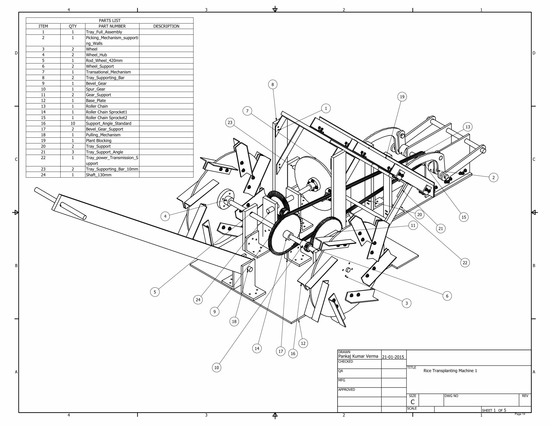
PARTS LIST
DESCRIPTIONPART NUMBERQTYITEM
Tray_Full_Assembly11
Picking_Mechanism_supporti
ng_Walls
12
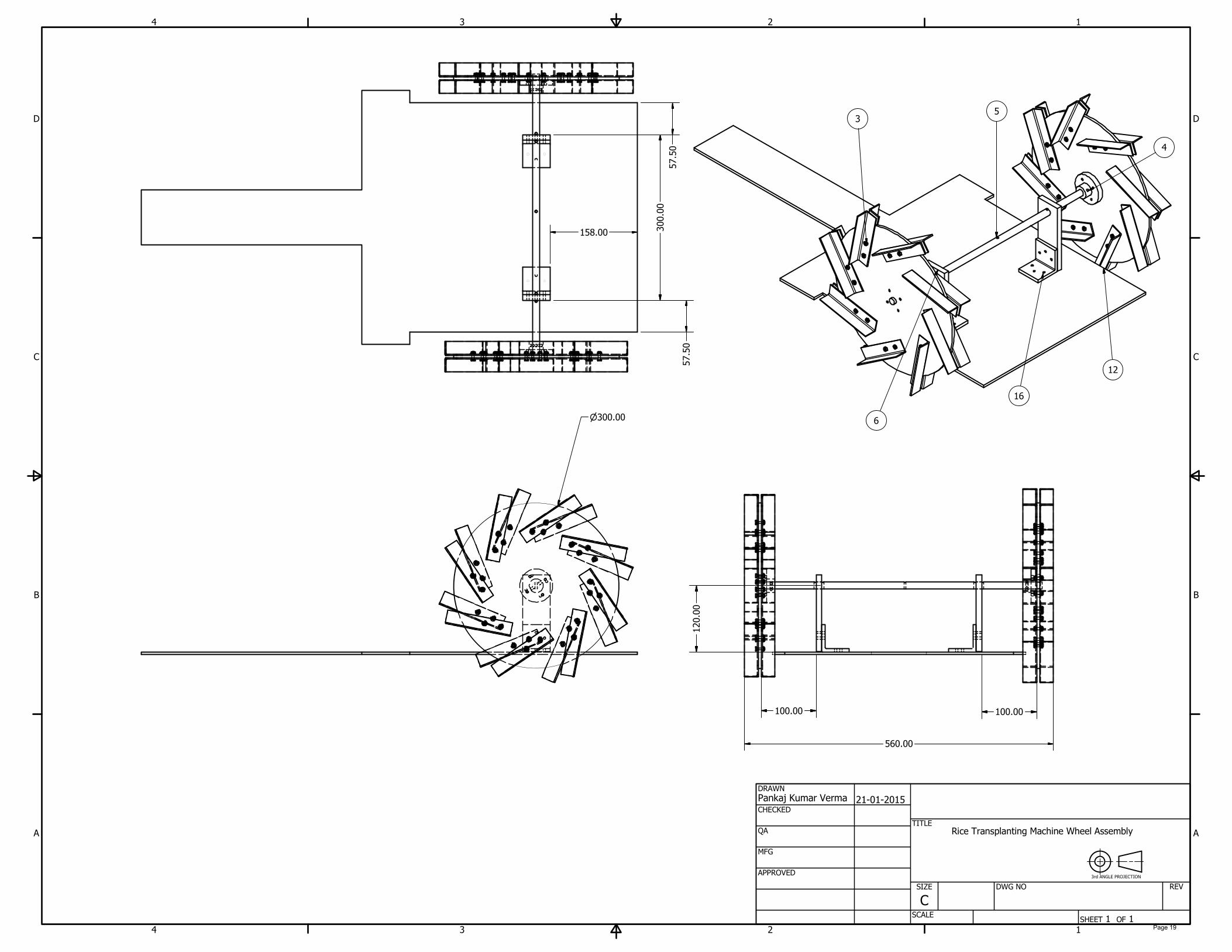
Wheel23
Wheel_Hub24
Rod_Wheel_420mm15
Wheel_Support26
Transational_Mechanism17
Tray_Supporting_Bar28
Bevel_Gear19
Spur_Gear110
Gear_Support211
Base_Plate112
Roller Chain113
Roller Chain Sprocket1114
Roller Chain Sprocket2115
Support_Angle_Standard1016
Bevel_Gear_Support217
Pulling_Mechanism118
Plant Blocking119
Tray_Support220
Tray_Support_Angle321
Tray_power_Transmission_S
upport
122
Tray_Supporting_Bar_10mm223
Shaft_130mm124
1
1
2
2
3
3
4
4
A A
B B
C C
D D
SHEET 1 OF 5
DRAWN
CHECKED
QA
MFG
APPROVED
Pankaj Kumar Verma
21-01-2015
DWG NO
TITLE
SIZE
C
SCALE
REV
9
8
1
10
7
5
3
16
6
12
14
17
11
13
24
19
20
22
21
2
23
15
18
4
Rice Transplanting Machine 1
Page 14

1
1
2
2
3
3
4
4
A A
B B
C C
D D
SHEET 5 OF 5
DRAWN
CHECKED
QA
MFG
APPROVED
Pankaj Kumar Verma
21-01-2015
DWG NO
TITLE
SIZE
C
SCALE
REV
Rice Transplanting Machine
Page 15
1
1
2
2
3
3
4
4
A A
B B
C C
D D
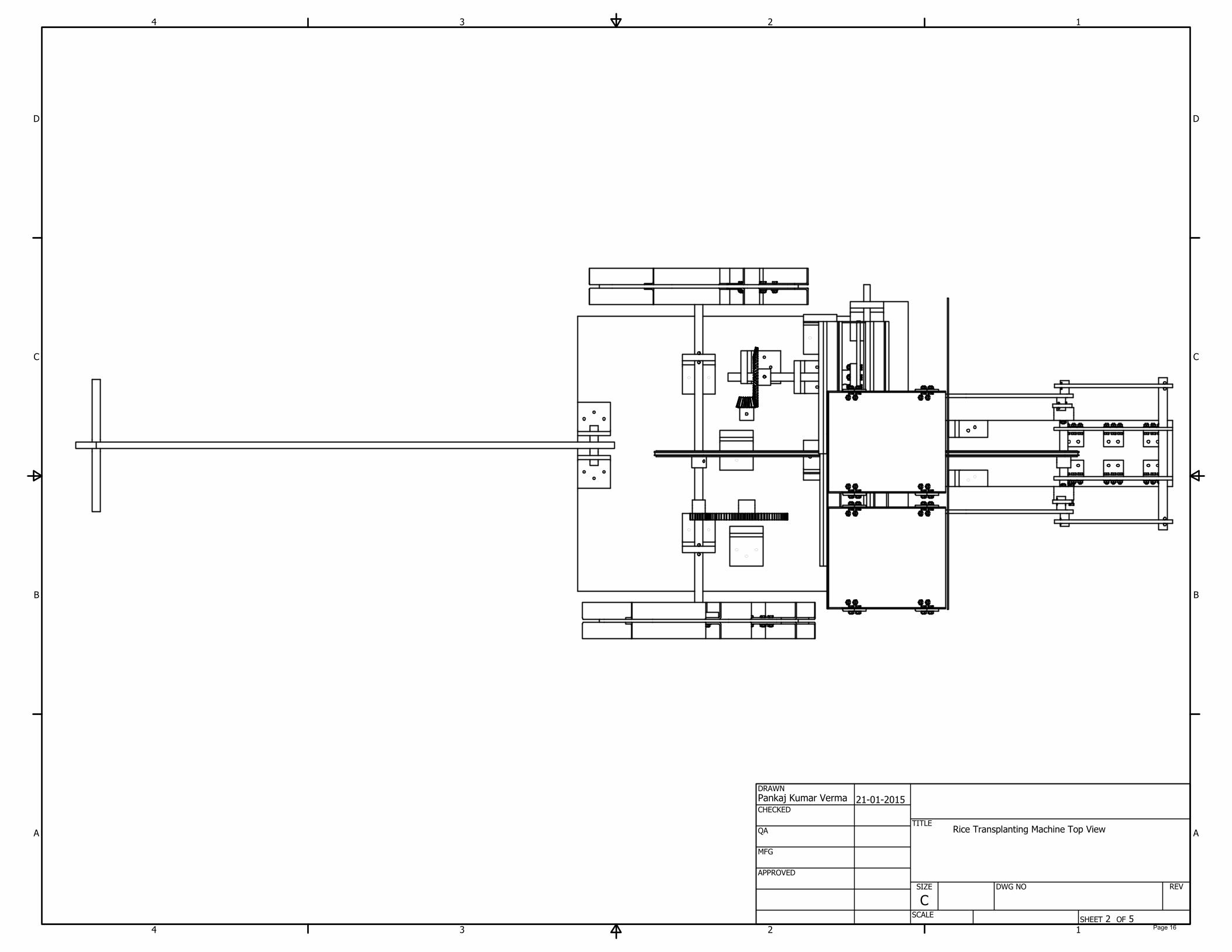
SHEET 2 OF 5
DRAWN
CHECKED
QA
MFG
APPROVED
Pankaj Kumar Verma
21-01-2015
DWG NO
TITLE
SIZE
C
SCALE
REV
Rice Transplanting Machine Top View
Page 16
1
1
2
2
3
3
4
4
A A
B B
C C
D D
SHEET 3 OF 5
DRAWN
CHECKED
QA
MFG
APPROVED
Pankaj Kumar Verma
21-01-2015
DWG NO
TITLE
SIZE
C
SCALE
REV
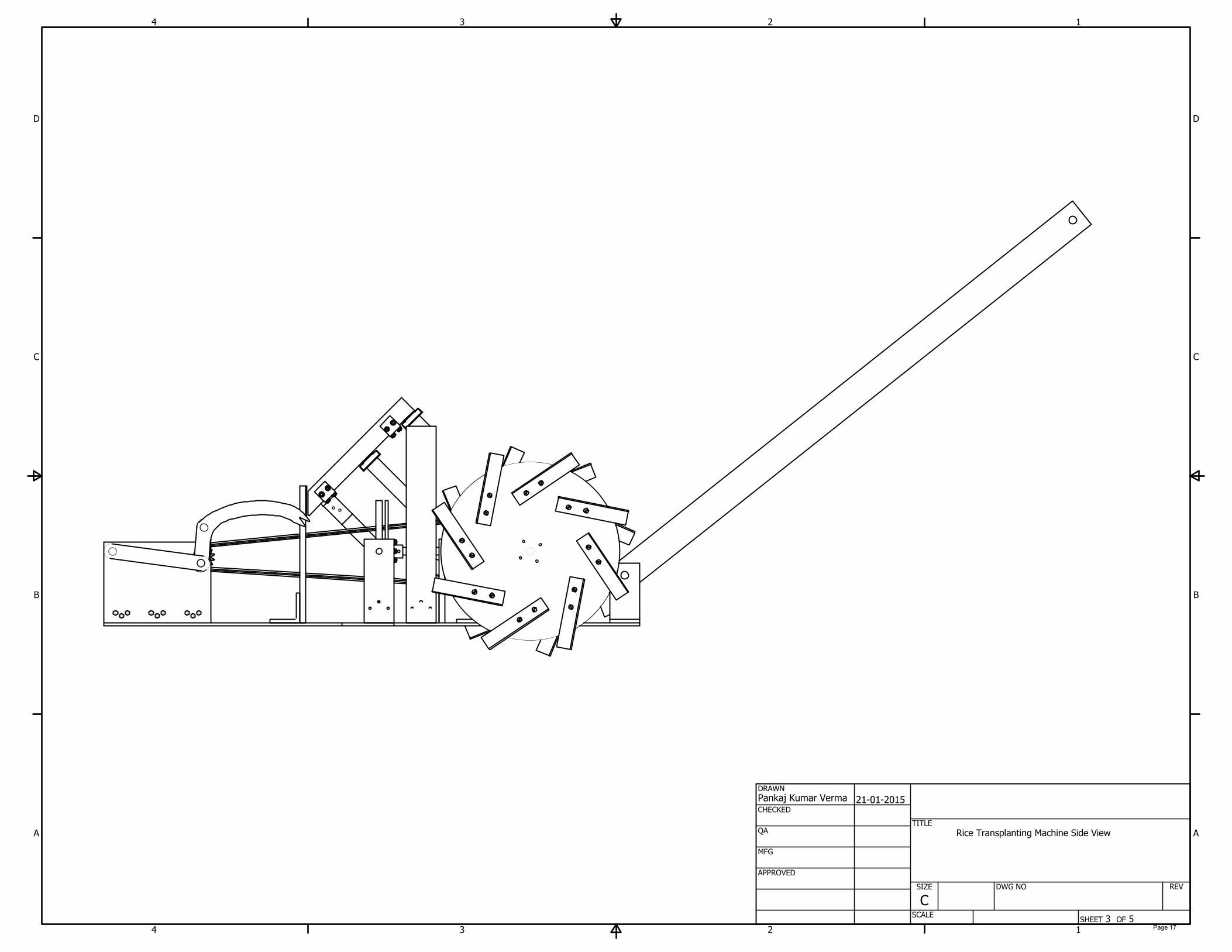
Rice Transplanting Machine Side View
Page 17
1
1
2
2
3
3
4
4
A A
B B
C C
D D
SHEET 4 OF 5
DRAWN
CHECKED
QA
MFG
APPROVED
Pankaj Kumar Verma
21-01-2015
DWG NO
TITLE
SIZE
C
SCALE
REV
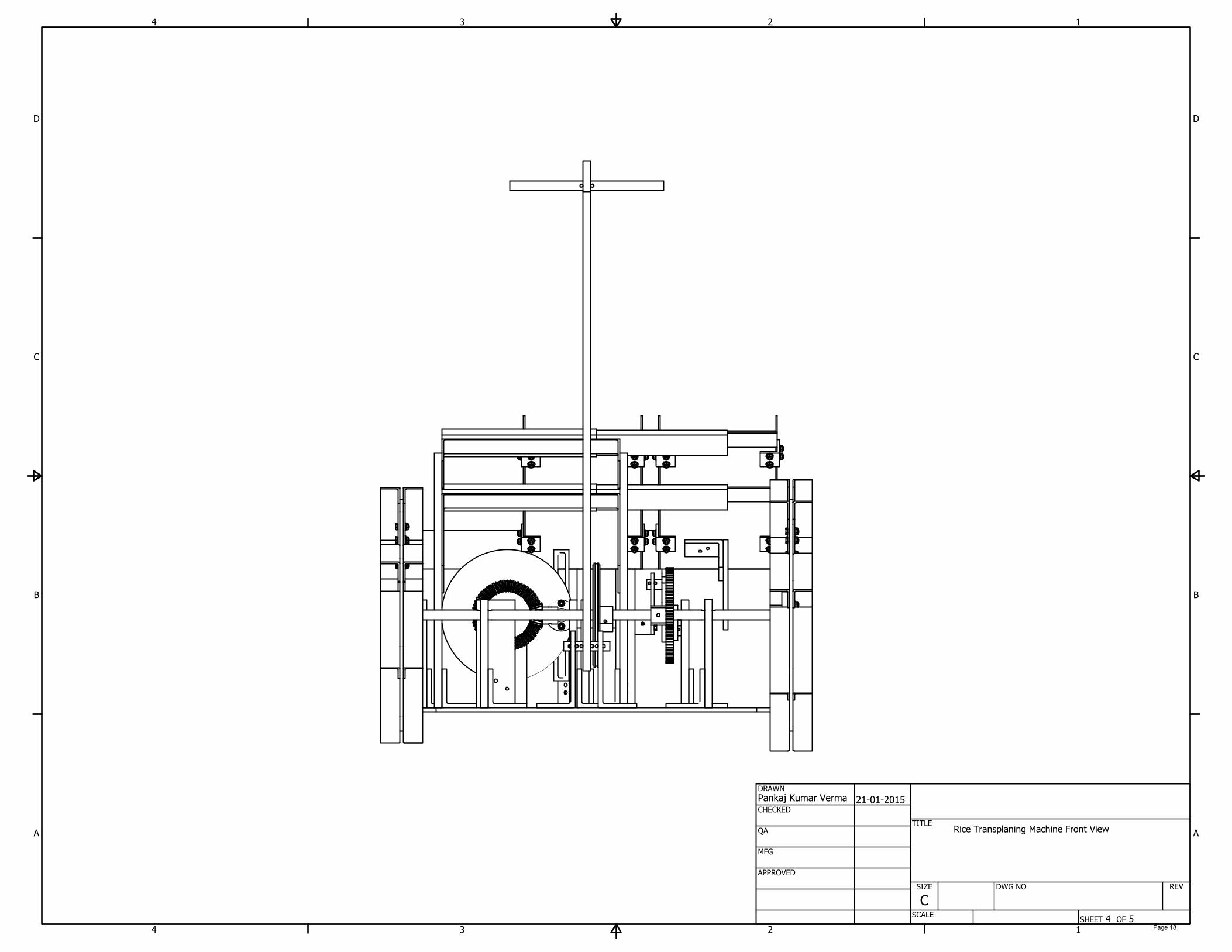
Rice Transplaning Machine Front View
Page 18
1
1
2
2
3
3
4
4
A A
B B
C C
D D
SHEET 1 OF 1
DRAWN
CHECKED
QA
MFG
APPROVED
Pankaj Kumar Verma
21-01-2015
DWG NO
TITLE
SIZE
C
SCALE
REV
57.50
57.50
158.00
300.00
120.00
100.00
100.00
560.00
300.00
3
12
5
6
16
4
Rice Transplanting Machine Wheel Assembly
3rd ANGLE PROJECTION
Page 19
1
1
2
2
3
3
4
4
A A
B B
C C
D D
SHEET 1 OF 1
DRAWN
CHECKED
QA
MFG
APPROVED
Pankaj Kumar Verma
21-01-2015
DWG NO
TITLE
SIZE
C
SCALE
REV
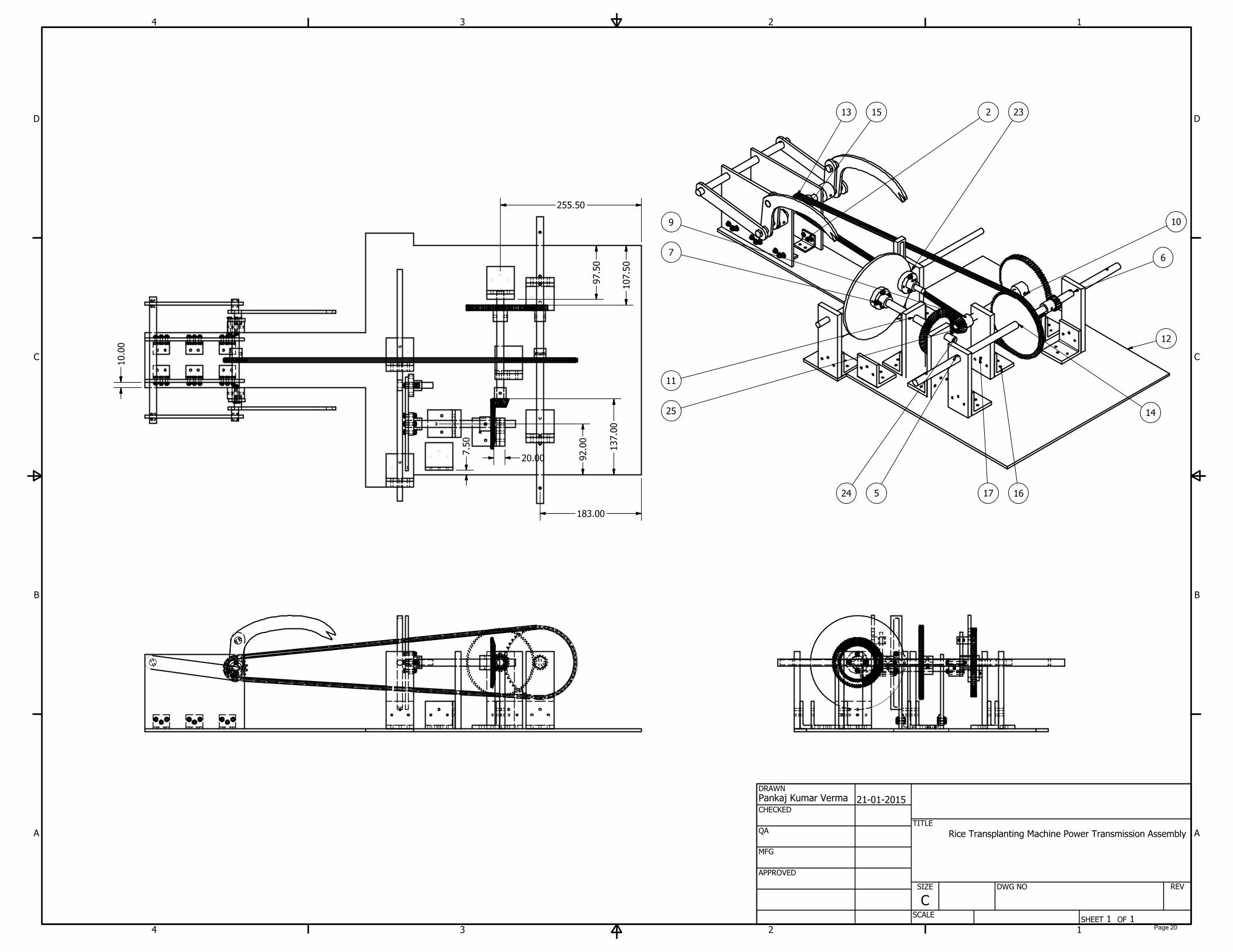
10.00
7.50
183.00
97.50
107.50
255.50
137.00
92.00
20.00
Rice Transplanting Machine Power Transmission Assembly
21513
12
25
14
17
23
11
9
1624
7
6
10
5
Page 20
1
1
2
2
3
3
4
4
A A
B B
C C
D D
SHEET 1 OF 1
DRAWN
CHECKED
QA
MFG
APPROVED
Pankaj Kumar Verma
21-01-2015
DWG NO
TITLE
SIZE
C
SCALE
REV
2.00
180.00
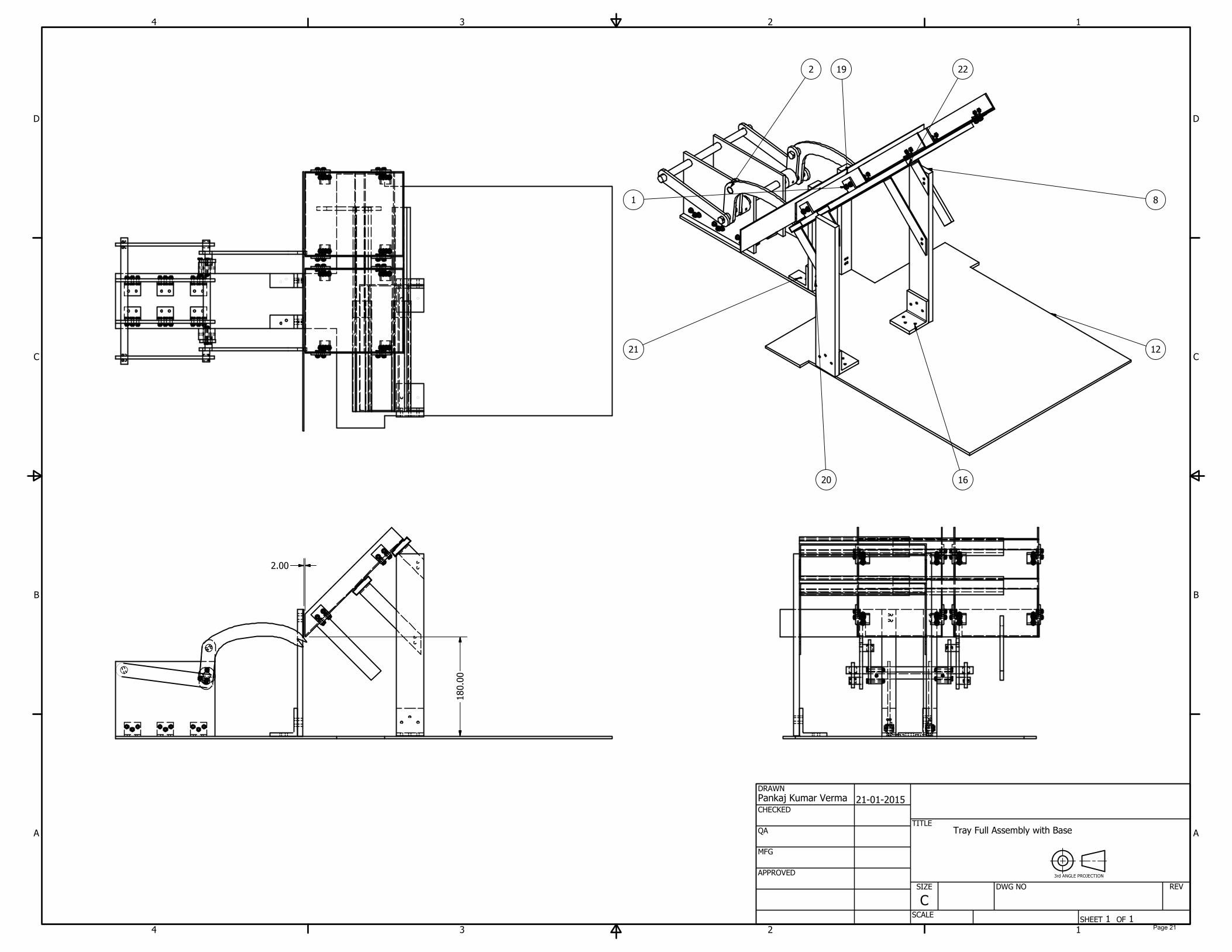
1
22
20
19
8
21
16
12
2
Tray Full Assembly with Base
3rd ANGLE PROJECTION
Page 21

PARTS LIST
DESCRIPTIONPART NUMBERQTYITEM
Picking_Mechanism_Support
ing_Wall
21
Picking_Mechanism_1.012
Picking_mechanism_Support
_Angle_1
63
Hexagon bolts with slot on
head - Product A and B
Bolt GB 29.1 M4 x 14184
Plain washers - Normal
series - Product grade A
ISO 7089 - 4 - 140 HV185
Hexagon nuts, style 1 -
Product grades A and B
ISO 4032 - M4186
1
1
2
2
3
3
4
4
A A
B B
C C
D D
SHEET 1 OF 1
DRAWN
CHECKED
QA
MFG
APPROVED
Pankaj Kumar Verma
19-01-2015
DWG NO
Picking_Mechanism_with_supporting_Walls
TITLE
SIZE
C
SCALE
REV
6 2
1
4
53
3rd ANGLE PROJECTION
Picking and Planting Mechanism with Support wall
All dimensions are in mm
180.00
15.00 30.0030.00
135.00
70.00
Page 22
PARTS LIST
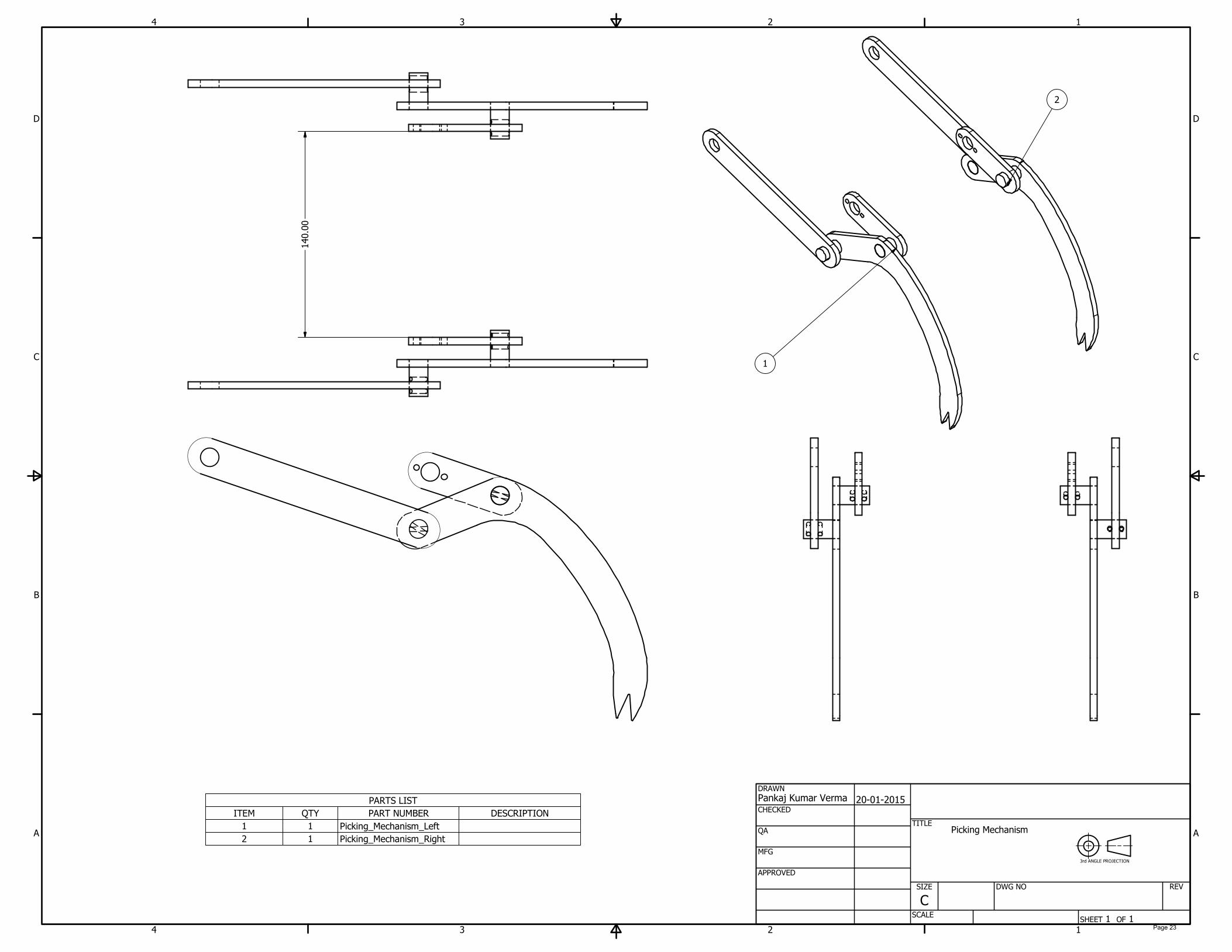
DESCRIPTIONPART NUMBERQTYITEM
Picking_Mechanism_Left11
Picking_Mechanism_Right12
1
1
2
2
3
3
4
4
A A
B B
C C
D D
SHEET 1 OF 1
DRAWN
CHECKED
QA
MFG
APPROVED
Pankaj Kumar Verma
20-01-2015
DWG NO
TITLE
SIZE
C
SCALE
REV
140.00
2
1
Picking Mechanism
3rd ANGLE PROJECTION
Page 23

PARTS LIST
DESCRIPTIONPART NUMBERQTYITEM
Picking_Arm_111
Picking_Arm_212
Picking_Arm_313
Picking_Arm_Shaft_124
1
1
2
2
3
3
4
4
A A
B B
C C
D D
SHEET 1 OF 1
DRAWN
CHECKED
QA
MFG
APPROVED
Pankaj Kumar Verma
20-01-2015
DWG NO
TITLE
SIZE
C
SCALE
REV
150.00
10.00
10.00
10.00
3
1 2
4
Picking Mechanism Left
3rd ANGLE PROJECTION
Page 24
PARTS LIST
DESCRIPTIONPART NUMBERQTYITEM
Picking_Arm_111
Picking_Arm_212
Picking_Arm_313
Picking_Arm_Shaft_124
1
1
2
2
3
3
4
4
A A
B B
C C
D D
SHEET 1 OF 1
DRAWN
CHECKED
QA
MFG
APPROVED
Pankaj Kumar Verma
20-01-2015
DWG NO
TITLE
SIZE
C
SCALE
REV
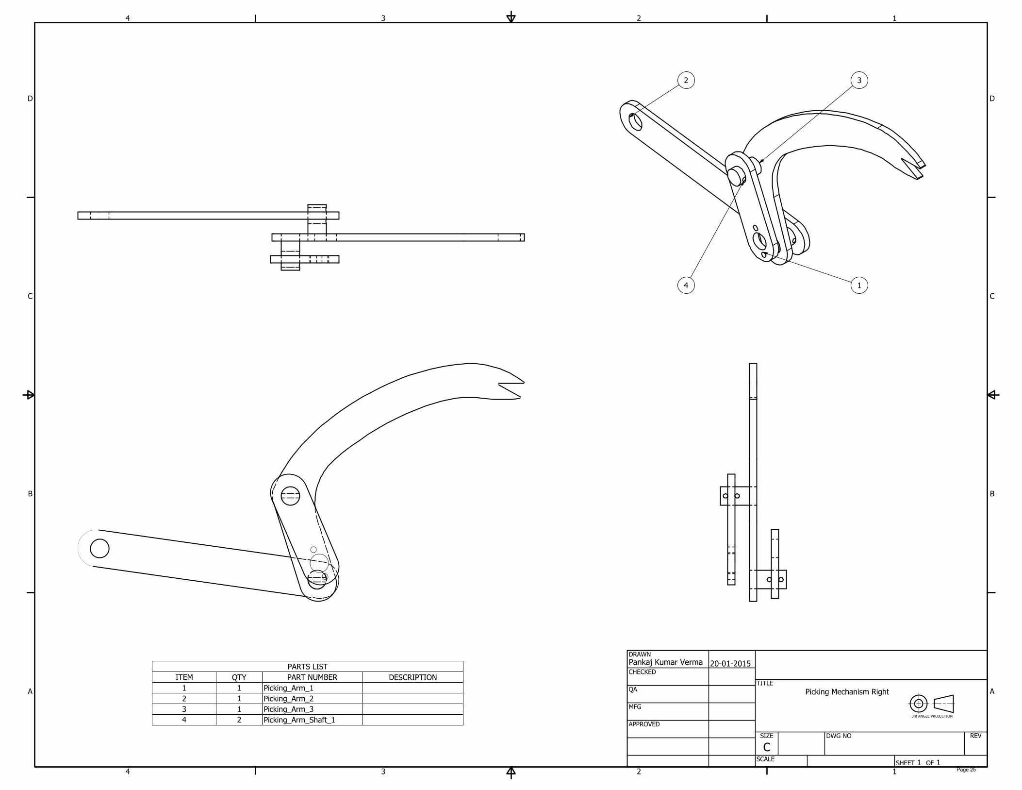
4
32
1
Picking Mechanism Right
3rd ANGLE PROJECTION
Page 25

PARTS LIST
DESCRIPTIONPART NUMBERQTYITEM
Tray21
Tray_Plate_122
slider23
Tray_Supporting_Angular_Pl
ate
14
Tray_Supporting_Angular_Pl
ate_2
15
1
1
2
2
3
3
4
4
A A
B B
C C
D D
SHEET 1 OF 1
DRAWN
CHECKED
QA
MFG
APPROVED
Pankaj Kumar Verma
20-01-2015
DWG NO
TITLE
SIZE
C
SCALE
REV
5
3
2
1
4
Tray Full Assembly
3rd ANGLE PROJECTION
21.00
75.00
5
.
3
0Page 26

PARTS LIST
DESCRIPTIONPART NUMBERQTYITEM
Tray_Lower_Part11
Tray_angle
42
Tray_Side23
Hexagon bolts with slot on
head - Product A and B
Bolt GB 29.1 M4 x 10164
Plain washers - Normal
series - Product grade A
ISO 7089 - 4 - 140 HV165
Hexagon nuts, style 1 -
Product grades A and B
ISO 4032 - M4166
1
1
2
2
3
3
4
4
A A
B B
C C
D D
SHEET 1 OF 1
DRAWN
CHECKED
QA
MFG
APPROVED
Pankaj Kumar Verma
20-01-2015
DWG NO
TITLE
SIZE
C
SCALE
REV
4
1
3
2
6
5
Tray
3rd ANGLE PROJECTION
Page 27
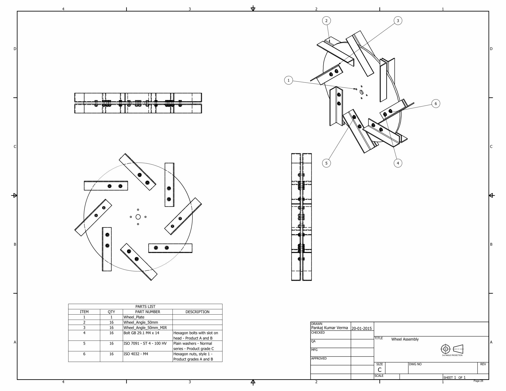
PARTS LIST
DESCRIPTIONPART NUMBERQTYITEM
Wheel_Plate11
Wheel_Angle_50mm162
Wheel_Angle_50mm_MIR163
Hexagon bolts with slot on
head - Product A and B
Bolt GB 29.1 M4 x 14164
Plain washers - Normal
series - Product grade C
ISO 7091 - ST 4 - 100 HV165
Hexagon nuts, style 1 -
Product grades A and B
ISO 4032 - M4166
1
1
2
2
3
3
4
4
A A
B B
C C
D D
SHEET 1 OF 1
DRAWN
CHECKED
QA
MFG
APPROVED
Pankaj Kumar Verma
20-01-2015
DWG NO
TITLE
SIZE
C
SCALE
REV
3
1
2
4
6
5
Wheel Assembly
3rd ANGLE PROJECTION
Page 28

PARTS LIST
DESCRIPTIONPART NUMBERQTYITEM
Translation_mechanism_Circ
ular_Plate
11
Translation_mechanism_Hub
1
12
Translation_mechanism_Hub
2
13
Translation_mechanism_Rod
_6mm
14
Translation_mechanism_Gro
ove_rod
15
Translation_mechanism_Rod
_10mm
26
Hexagon bolts with slot on head - Product A and BBolt GB 29.1 M4 x 2067
Plain washers - Normal series - Product grade AISO 7089 - 4 - 140 HV68
Hexagon nuts, style 1 - Product grades A and BISO 4032 - M469
1
1
2
2
3
3
4
4
A A
B B
C C
D D
SHEET 1 OF 1
DRAWN
CHECKED
QA
MFG
APPROVED
Pankaj Kumar Verma
20-01-2015
DWG NO
TITLE
SIZE
C
SCALE
REV
9
1
5
7
8
4
2
6
3
Translational Mechanism - Whitworth Mechanism
3rd ANGLE PROJECTION
Page 29
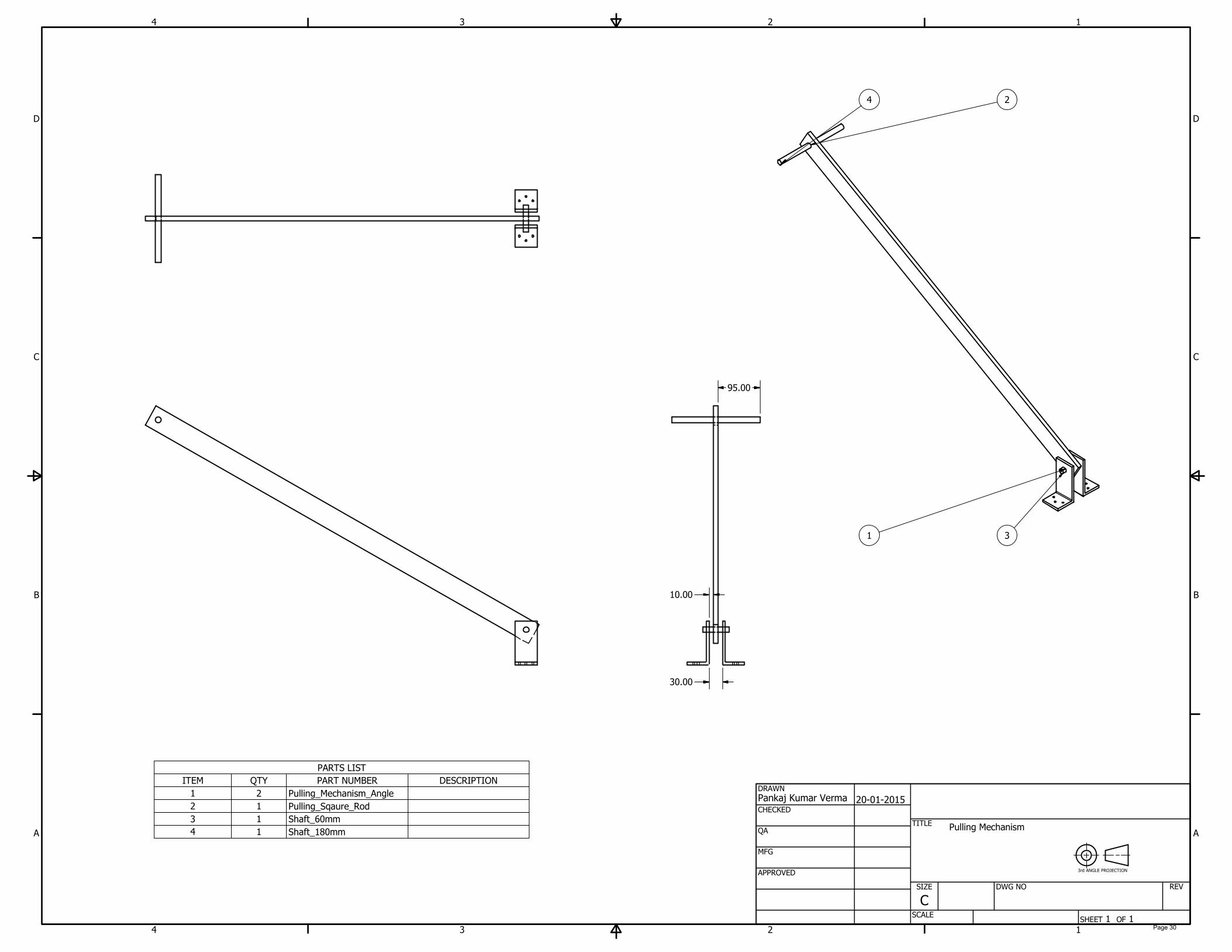
PARTS LIST
DESCRIPTIONPART NUMBERQTYITEM
Pulling_Mechanism_Angle21
Pulling_Sqaure_Rod12
Shaft_60mm13
Shaft_180mm14
1
1
2
2
3
3
4
4
A A
B B
C C
D D
SHEET 1 OF 1
DRAWN
CHECKED
QA
MFG
APPROVED
Pankaj Kumar Verma
20-01-2015
DWG NO
TITLE
SIZE
C
SCALE
REV
4
3
2
1
30.00
10.00
95.00
Pulling Mechanism
3rd ANGLE PROJECTION
Page 30
APPENDIX – 3
Isometric Drawing of Planting Unit Assembly and Parts
Page 31
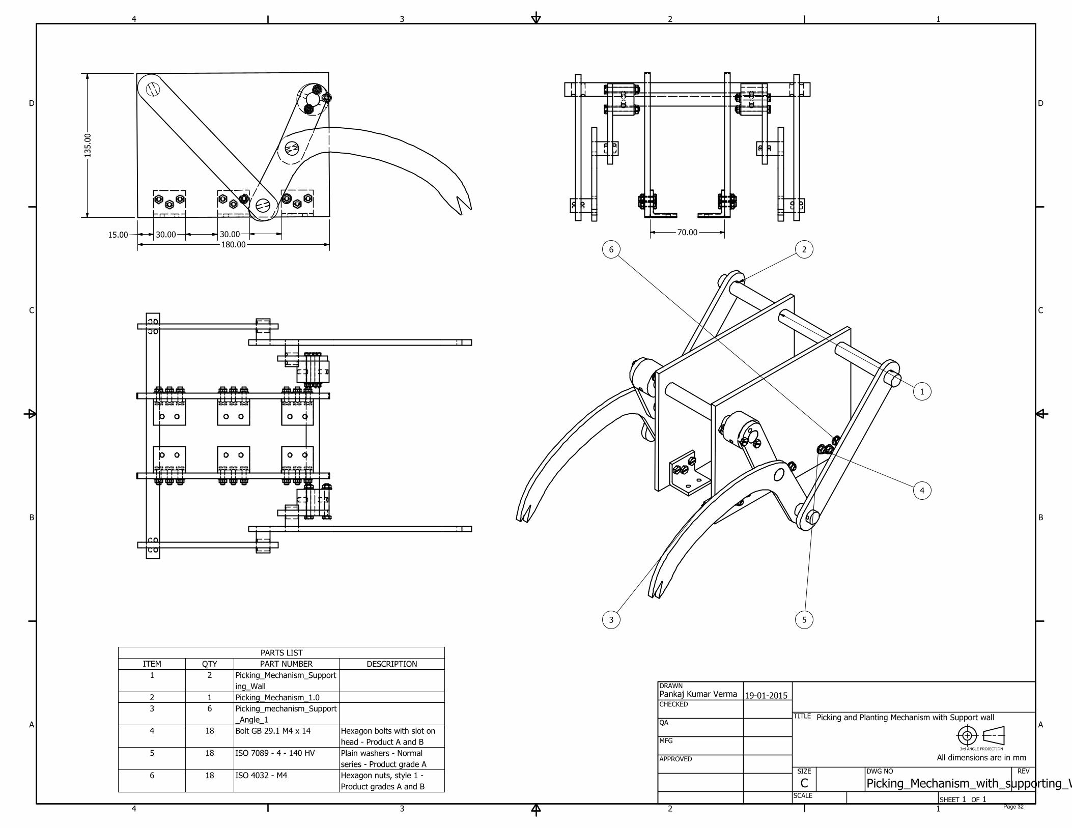
PARTS LIST
DESCRIPTIONPART NUMBERQTYITEM
Picking_Mechanism_Support
ing_Wall
21
Picking_Mechanism_1.012
Picking_mechanism_Support
_Angle_1
63
Hexagon bolts with slot on
head - Product A and B
Bolt GB 29.1 M4 x 14184
Plain washers - Normal
series - Product grade A
ISO 7089 - 4 - 140 HV185
Hexagon nuts, style 1 -
Product grades A and B
ISO 4032 - M4186
1
1
2
2
3
3
4
4
A A
B B
C C
D D
SHEET 1 OF 1
DRAWN
CHECKED
QA
MFG
APPROVED
Pankaj Kumar Verma
19-01-2015
DWG NO
Picking_Mechanism_with_supporting_Walls
TITLE
SIZE
C
SCALE
REV
6 2
1
4
53
3rd ANGLE PROJECTION
Picking and Planting Mechanism with Support wall
All dimensions are in mm
180.00
15.00 30.0030.00
135.00
70.00
Page 32

PARTS LIST
DESCRIPTIONPART NUMBERQTYITEM
Picking_Mechanism_Left11
Picking_Mechanism_Right12
1
1
2
2
3
3
4
4
A A
B B
C C
D D
SHEET 1 OF 1
DRAWN
CHECKED
QA
MFG
APPROVED
Pankaj Kumar Verma
20-01-2015
DWG NO
TITLE
SIZE
C
SCALE
REV
140.00
2
1
Picking Mechanism
3rd ANGLE PROJECTION
Page 33
PARTS LIST
DESCRIPTIONPART NUMBERQTYITEM
Picking_Arm_111
Picking_Arm_212
Picking_Arm_313
Picking_Arm_Shaft_124
1
1
2
2
3
3
4
4
A A
B B
C C
D D
SHEET 1 OF 1
DRAWN
CHECKED
QA
MFG
APPROVED
Pankaj Kumar Verma
20-01-2015
DWG NO
TITLE
SIZE
C
SCALE
REV
150.00
10.00
10.00
10.00
3
1 2
4
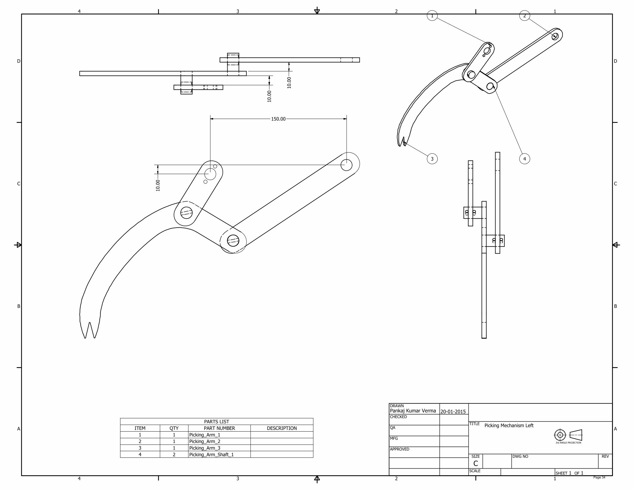
Picking Mechanism Left
3rd ANGLE PROJECTION
Page 34

PARTS LIST
DESCRIPTIONPART NUMBERQTYITEM
Picking_Arm_111
Picking_Arm_212
Picking_Arm_313
Picking_Arm_Shaft_124
1
1
2
2
3
3
4
4
A A
B B
C C
D D
SHEET 1 OF 1
DRAWN
CHECKED
QA
MFG
APPROVED
Pankaj Kumar Verma
20-01-2015
DWG NO
TITLE
SIZE
C
SCALE
REV
4
32
1
Picking Mechanism Right
3rd ANGLE PROJECTION
Page 35

1
1
2
2
3
3
4
4
A A
B B
C C
D D
SHEET 1 OF 1
DRAWN
CHECKED
QA
MFG
APPROVED
Pankaj Kumar Verma
20-01-2015
DWG NO
Picking_Arm_1
TITLE
SIZE
C
SCALE
REV
12.70
50.00
12.70
15.00
12.50
80.00
12.50
12.50
R12.50
10.00
10.00
4.00
4.00
5.00
Picking Arm 1
3rd ANGLE PROJECTION
Material Required: 25mm * 5mm * 80mm Mild Steel Flat Quantity: 2
Page 36
1
1
2
2
3
3
4
4
A A
B B
C C
D D
SHEET 1 OF 1
DRAWN
CHECKED
QA
MFG
APPROVED
Pankaj Kumar Verma
20-01-2015
DWG NO
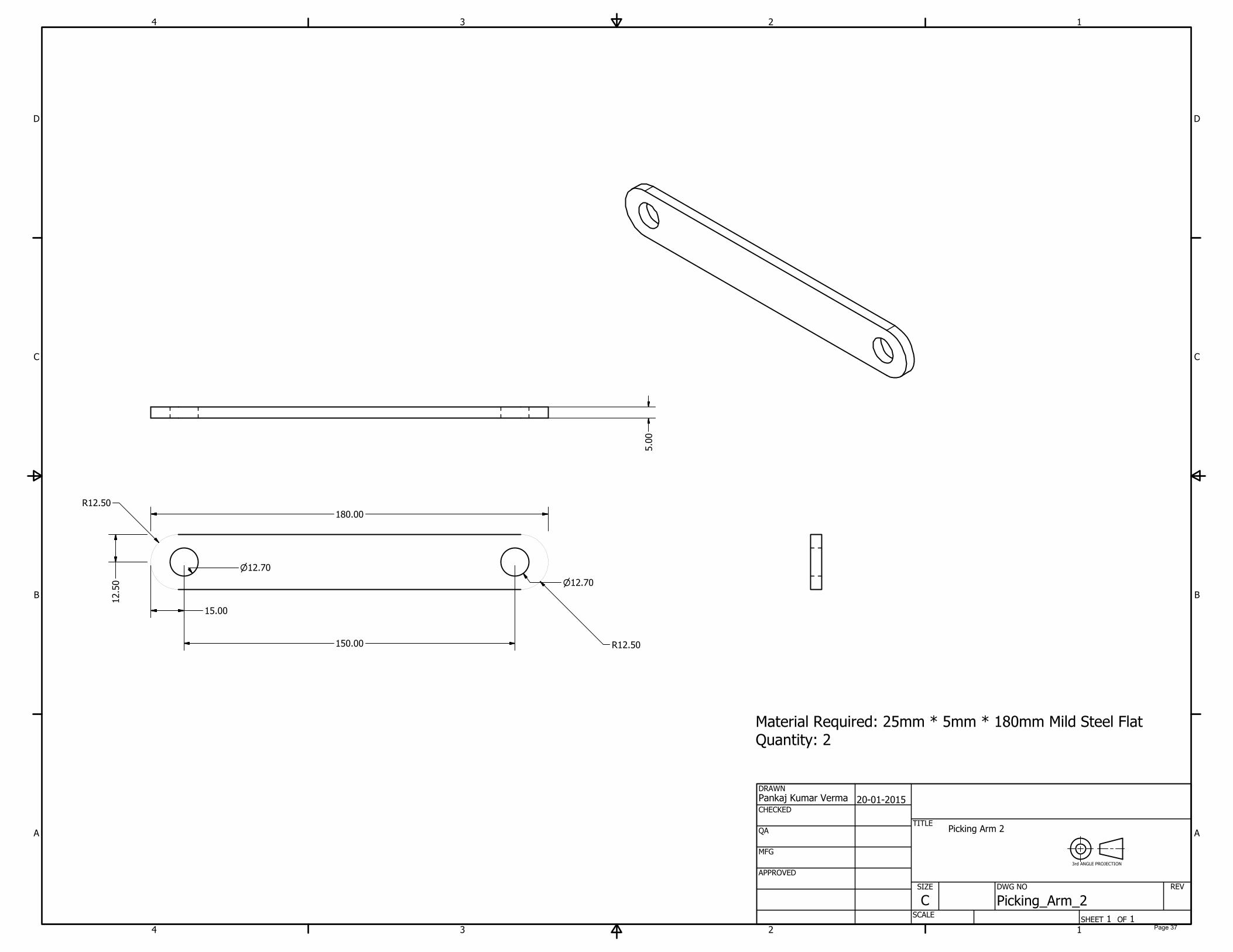
Picking_Arm_2
TITLE
SIZE
C
SCALE
REV
12.70
150.00
12.70
15.00
12.50
180.00
R12.50
R12.50
5.00
Picking Arm 2
3rd ANGLE PROJECTION
Material Required: 25mm * 5mm * 180mm Mild Steel Flat Quantity: 2
Page 37
1
1
2
2
3
3
4
4
A A
B B
C C
D D
SHEET 1 OF 1
DRAWN
CHECKED
QA
MFG
APPROVED
Pankaj Kumar Verma
20-01-2015
DWG NO
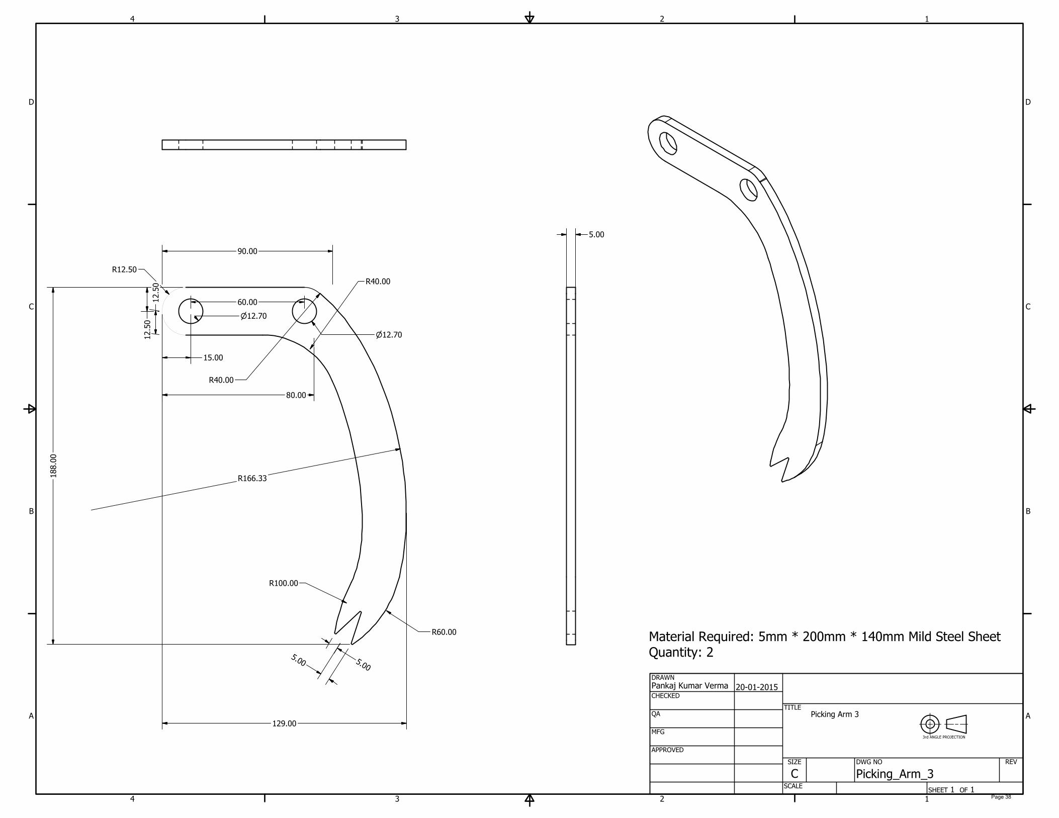
Picking_Arm_3
TITLE
SIZE
C
SCALE
REV
12.70
60.00
15.00
12.50
90.00
12.50
80.00
12.70
5
.
0
0
5
.
0
0
R40.00
R40.00
R100.00
R60.00
R12.50
5.00
Picking Arm 3
3rd ANGLE PROJECTION
R166.33
129.00
188.00
Material Required: 5mm * 200mm * 140mm Mild Steel Sheet
Quantity: 2
Page 38

1
1
2
2
3
3
4
4
A A
B B
C C
D D
SHEET 1 OF 1
DRAWN
CHECKED
QA
MFG
APPROVED
Pankaj Kumar Verma
20-01-2015
DWG NO
Picking_Arm_Shaft_1
TITLE
SIZE
C
SCALE
REV
25.00
3.50
8.00
R1.50
R1.50
12.70
Picking Arm Shaft 1.0
3rd ANGLE PROJECTION
Material Required: 12.7mm Dia * 25mm Mild Steel Rod
Quantity: 4
Page 39
1
1
2
2
3
3
4
4
A A
B B
C C
D D
SHEET 1 OF 1
DRAWN
CHECKED
QA
MFG
APPROVED
Pankaj Kumar Verma
20-01-2015
DWG NO
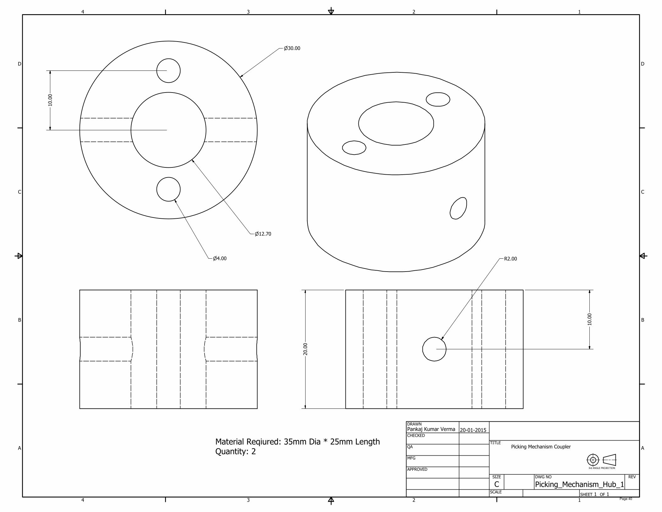
Picking_Mechanism_Hub_1
TITLE
SIZE
C
SCALE
REV
30.00
12.70
4.00
10.00
R2.00
10.00
20.00
Picking Mechanism Coupler
3rd ANGLE PROJECTION
Material Reqiured: 35mm Dia * 25mm Length
Quantity: 2
Page 40
1
1
2
2
3
3
4
4
A A
B B
C C
D D
SHEET 1 OF 1
DRAWN
CHECKED
QA
MFG
APPROVED
Pankaj Kumar Verma
20-01-2015
DWG NO
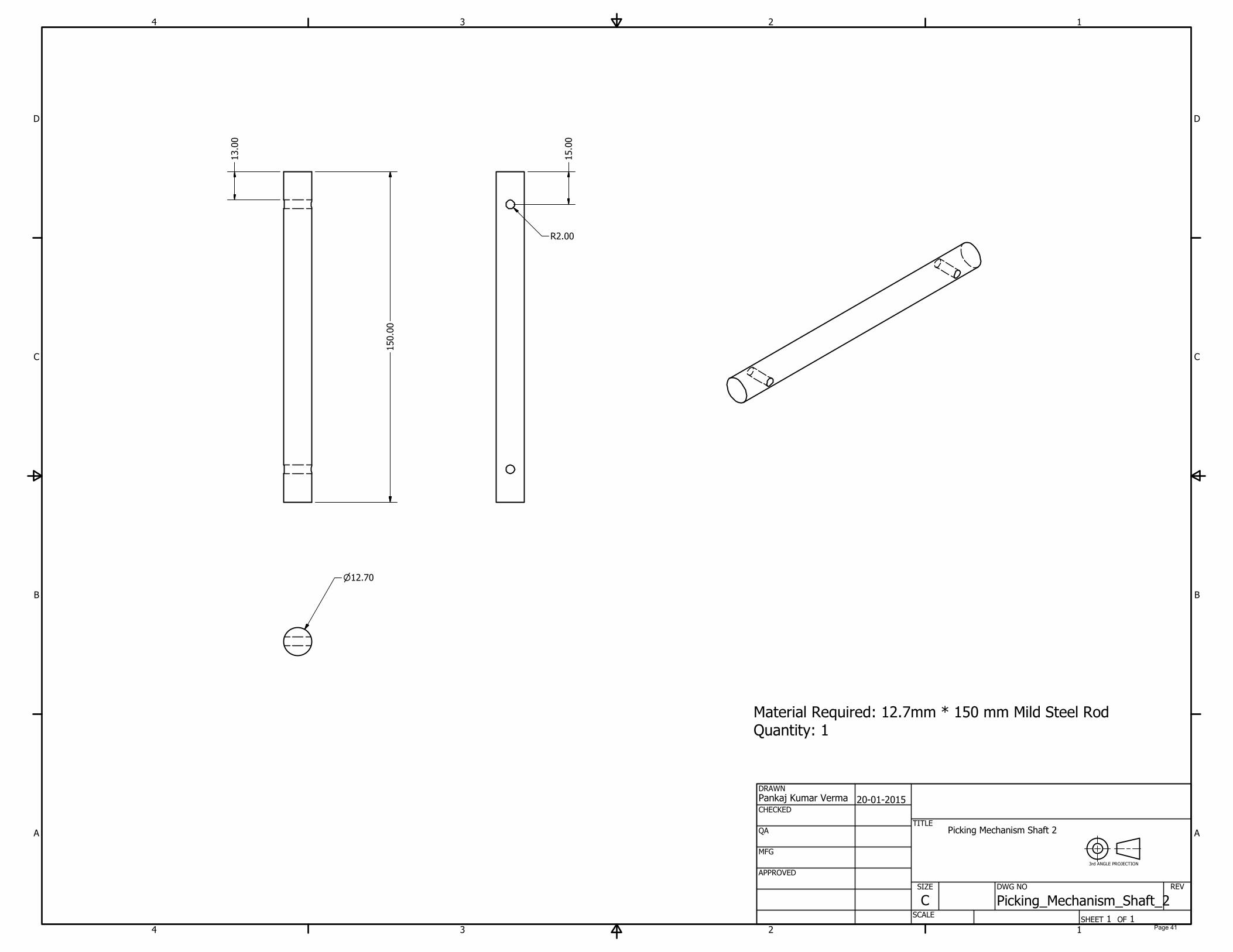
Picking_Mechanism_Shaft_2
TITLE
SIZE
C
SCALE
REV
150.00
13.00
15.00
R2.00
12.70
Picking Mechanism Shaft 2
3rd ANGLE PROJECTION
Material Required: 12.7mm * 150 mm Mild Steel Rod
Quantity: 1
Page 41

1
1
2
2
3
3
4
4
A A
B B
C C
D D
SHEET 1 OF 1
DRAWN
CHECKED
QA
MFG
APPROVED
Pankaj Kumar Verma
19-01-2015
DWG NO
Picking_mechanism_Support_Angle_1
TITLE
SIZE
C
SCALE
REV
25.00
3.00
22.00
22.00
R2.00
8.00
8.00
14.00
8.00 5.00
10.00
5.00
Picking Mechanism Support Angle
3rd ANGLE PROJECTION
Material Required: 25mm * 25mm * 3mm Mild Steel Angle
Quantity: 6
Page 42

1
1
2
2
3
3
4
4
A A
B B
C C
D D
SHEET 1 OF 1
DRAWN
CHECKED
QA
MFG
APPROVED
Pankaj Kumar Verma
19-01-2015
DWG NO
Picking_Mechanism_Supporting_Wall
TITLE
SIZE
C
SCALE
REV
135.00
180.00
75.00
110.00
75.00
12.70
12.70
17.00
20.00
10.00
10.00
5.00
4.00
4.00
60.00
4.00
5.00
Picking Mechanism Supporting Wall
3rd ANGLE PROJECTION
Material Required: 135mm * 180mm * 5mm Mild Steel Sheet
Quantity: 2
Page 43
1
1
2
2
3
3
4
4
A A
B B
C C
D D
SHEET 1 OF 1
DRAWN
CHECKED
QA
MFG
APPROVED
Pankaj Kumar Verma
20-01-2015
DWG NO
Picking_Mechnism_Shaft_1
TITLE
SIZE
C
SCALE
REV
230.00
12.70
R2.00
R2.00
8.00
17.00
Picking Mechanism Shaft 1
3rd ANGLE PROJECTION
Material Required: 12.7mm Dia * 230mm Mild Steel Rod
Quantity: 1
Page 44

APPENDIX – 4
Isometric Drawing of Tray Assembly and Parts
Page 45
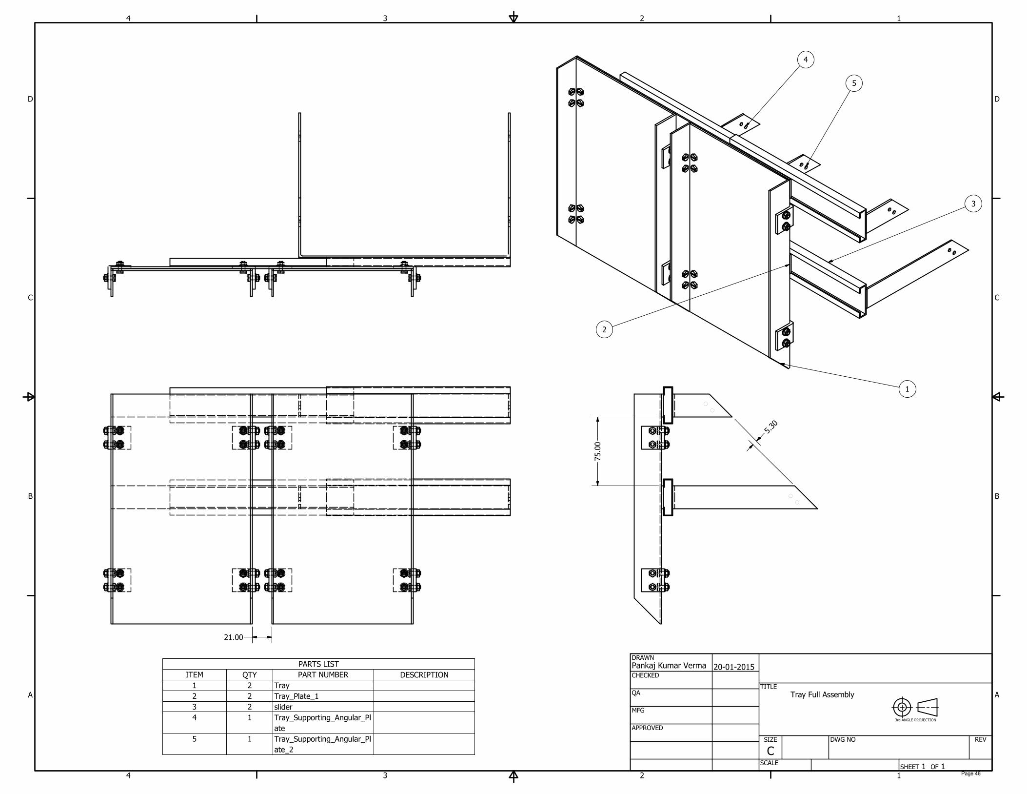
PARTS LIST
DESCRIPTIONPART NUMBERQTYITEM
Tray21
Tray_Plate_122
slider23
Tray_Supporting_Angular_Pl
ate
14
Tray_Supporting_Angular_Pl
ate_2
15
1
1
2
2
3
3
4
4
A A
B B
C C
D D
SHEET 1 OF 1
DRAWN
CHECKED
QA
MFG
APPROVED
Pankaj Kumar Verma
20-01-2015
DWG NO
TITLE
SIZE
C
SCALE
REV
5
3
2
1
4
Tray Full Assembly
3rd ANGLE PROJECTION
21.00
75.00
5
.
3
0Page 46
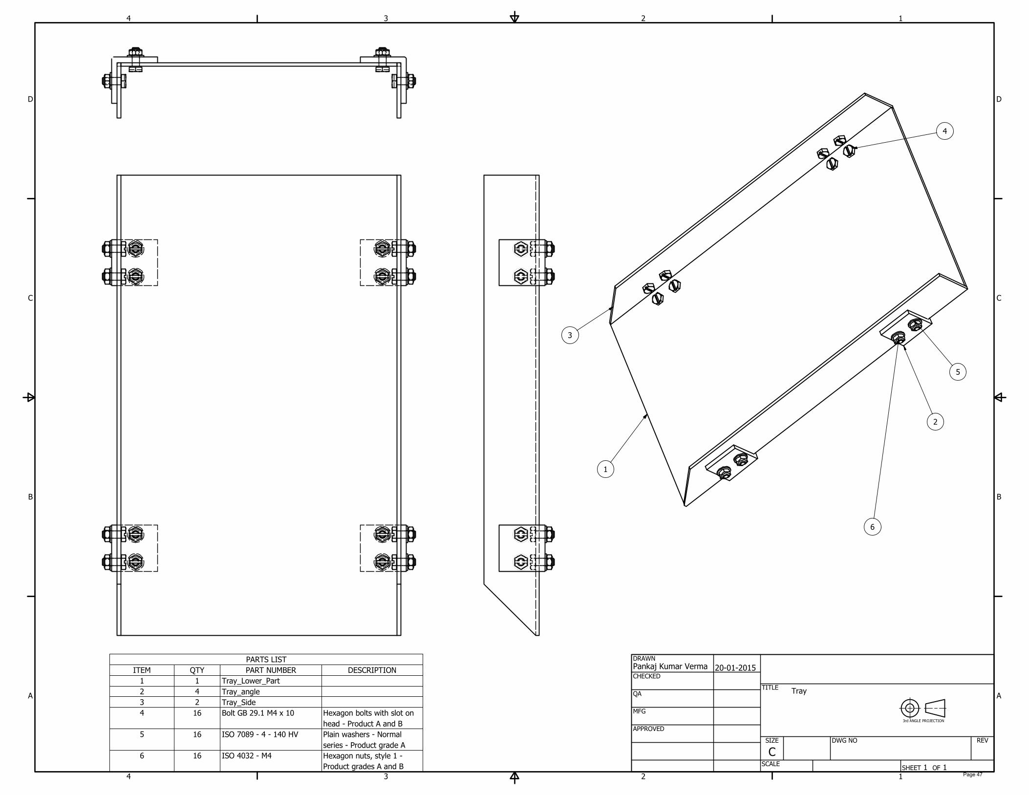
PARTS LIST
DESCRIPTIONPART NUMBERQTYITEM
Tray_Lower_Part11
Tray_angle
42
Tray_Side23
Hexagon bolts with slot on
head - Product A and B
Bolt GB 29.1 M4 x 10164
Plain washers - Normal
series - Product grade A
ISO 7089 - 4 - 140 HV165
Hexagon nuts, style 1 -
Product grades A and B
ISO 4032 - M4166
1
1
2
2
3
3
4
4
A A
B B
C C
D D
SHEET 1 OF 1
DRAWN
CHECKED
QA
MFG
APPROVED
Pankaj Kumar Verma
20-01-2015
DWG NO
TITLE
SIZE
C
SCALE
REV
4
1
3
2
6
5
Tray
3rd ANGLE PROJECTION
Page 47
1
1
2
2
3
3
4
4
A A
B B
C C
D D
SHEET 1 OF 1
DRAWN
CHECKED
QA
MFG
APPROVED
Pankaj Kumar Verma
20-01-2015
DWG NO
Tray_Lower_Part
TITLE
SIZE
C
SCALE
REV
8.00
40.00
15.00
4.00
4.00
150.00
250.00
2.00
Tray Lower Part
3rd ANGLE PROJECTION
Material Required: 250mm * 150mm * 2mm Mild Steel Sheet
Quantity: 2
Page 48
1
1
2
2
3
3
4
4
A A
B B
C C
D D
SHEET 1 OF 1
DRAWN
CHECKED
QA
MFG
APPROVED
Pankaj Kumar Verma
20-01-2015
DWG NO
Tray_Side
TITLE
SIZE
C
SCALE
REV
10.00
40.00
15.00
4.00
4.00
28.00
45.0°
30.00
250.00
2.00
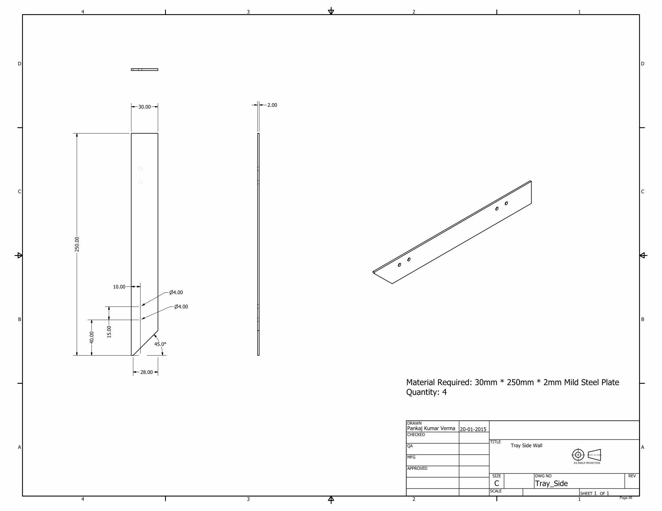
Tray Side Wall
3rd ANGLE PROJECTION
Material Required: 30mm * 250mm * 2mm Mild Steel Plate
Quantity: 4
Page 49
1
1
2
2
3
3
4
4
A A
B B
C C
D D
SHEET 1 OF 1
DRAWN
CHECKED
QA
MFG
APPROVED
Pankaj Kumar Verma
20-01-2015
DWG NO
Tray_angle
TITLE
SIZE
C
SCALE
REV
13.00
5.00
15.00
4.00
4.00
25.00
3.00
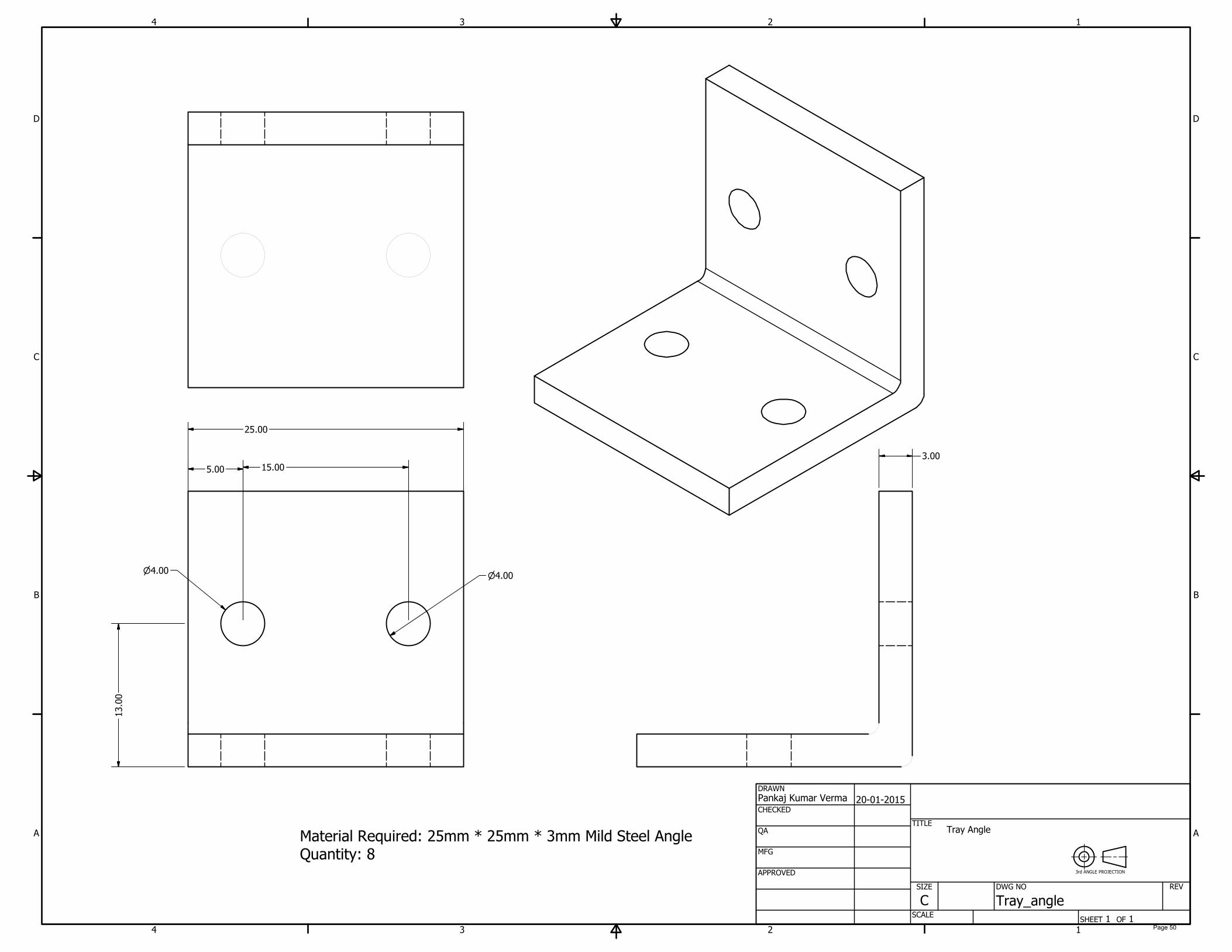
Tray Angle
3rd ANGLE PROJECTION
Material Required: 25mm * 25mm * 3mm Mild Steel Angle
Quantity: 8
Page 50

1
1
2
2
3
3
4
4
A A
B B
C C
D D
SHEET 1 OF 1
DRAWN
CHECKED
QA
MFG
APPROVED
Pankaj Kumar Verma
20-01-2015
DWG NO
Tray_anglular_Plate
TITLE
SIZE
C
SCALE
REV
2.00
230.00
15.00
1
0
.
0
0
1
0
.
0
0
4.00
4.00
2.00
65.00
40.00
25.00
Tray Supporting Angular Plate 1
3rd ANGLE PROJECTION
Material Required: 25mm * 360mm * 2mm Mild Steel Flat Quantity: 1
Page 51

1
1
2
2
3
3
4
4
A A
B B
C C
D D
SHEET 1 OF 1
DRAWN
CHECKED
QA
MFG
APPROVED
Pankaj Kumar Verma
20-01-2015
DWG NO
Tray_Supporting_Angular_Plate_2
TITLE
SIZE
C
SCALE
REV
25.00
230.00
132.50
25.00
45.0°
15.00
1
0
.
0
0
1
0
.
0
0
4.00
4.00
2.00
155.50
2.00
Tray Supporting Angular Plate 2
3rd ANGLE PROJECTION
Material Required: 25mm * 2mm * 550mm Mild Steel Plate
Quantity: 1
Page 52
APPENDIX – 5
Isometric Drawing of Wheel Assembly and Parts
Page 53

PARTS LIST
DESCRIPTIONPART NUMBERQTYITEM
Wheel_Plate11
Wheel_Angle_50mm162
Wheel_Angle_50mm_MIR163
Hexagon bolts with slot on
head - Product A and B
Bolt GB 29.1 M4 x 14164
Plain washers - Normal
series - Product grade C
ISO 7091 - ST 4 - 100 HV165
Hexagon nuts, style 1 -
Product grades A and B
ISO 4032 - M4166
1
1
2
2
3
3
4
4
A A
B B
C C
D D
SHEET 1 OF 1
DRAWN
CHECKED
QA
MFG
APPROVED
Pankaj Kumar Verma
20-01-2015
DWG NO
TITLE
SIZE
C
SCALE
REV
3
1
2
4
6
5
Wheel Assembly
3rd ANGLE PROJECTION
Page 54

1
1
2
2
3
3
4
4
A A
B B
C C
D D
SHEET 1 OF 1
DRAWN
CHECKED
QA
MFG
APPROVED
Pankaj Kumar Verma
20-01-2015
DWG NO
Wheel_Plate
TITLE
SIZE
C
SCALE
REV
300.00
12.70
140.00
135.0°
2
0
.
0
0
14.00
3
0
.
0
0
4.00
4.00
20.00
4.00
5.00
Wheel Plate
3rd ANGLE PROJECTION
Material Required: 300mm * 300mm * 5mm Mild Steel Rod
Quantity: 2
Page 55
1
1
2
2
3
3
4
4
A A
B B
C C
D D
SHEET 1 OF 1
DRAWN
CHECKED
QA
MFG
APPROVED
Pankaj Kumar Verma
20-01-2015
DWG NO
Wheel_Angle_50mm
TITLE
SIZE
C
SCALE
REV
20.00
14.00
14.00
30.00
4.00
4.00
2.00
25.00
120.00
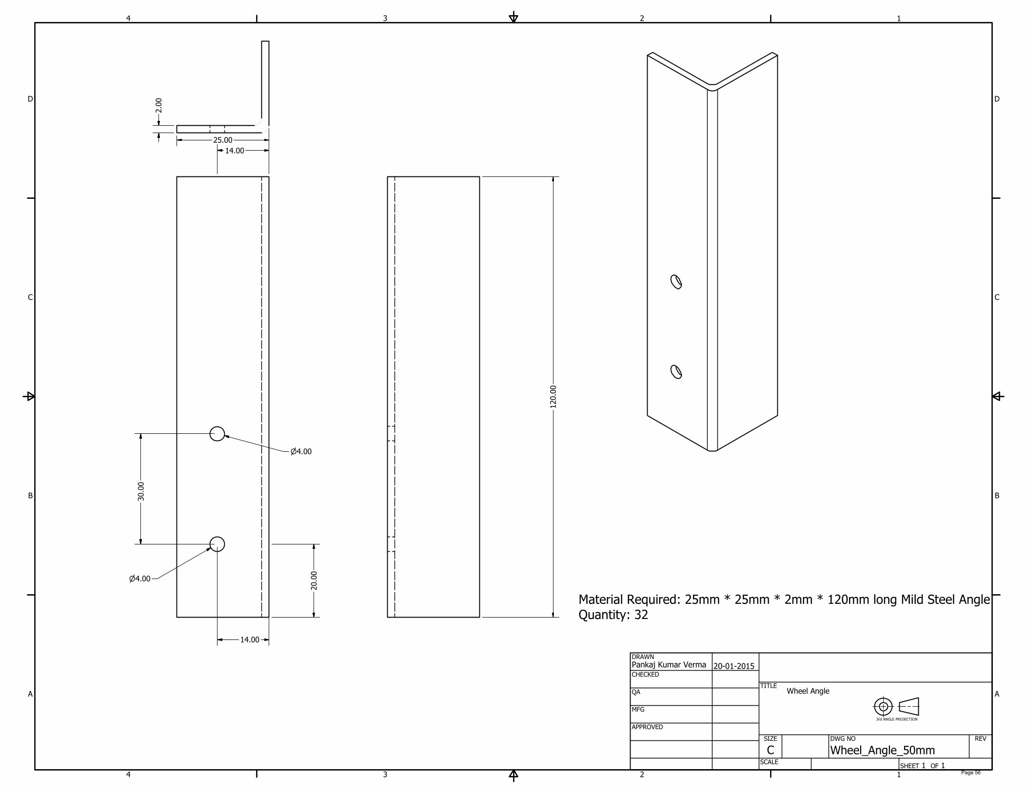
Wheel Angle
3rd ANGLE PROJECTION
Material Required: 25mm * 25mm * 2mm * 120mm long Mild Steel Angle
Quantity: 32
Page 56

1
1
2
2
3
3
4
4
A A
B B
C C
D D
SHEET 1 OF 1
DRAWN
CHECKED
QA
MFG
APPROVED
Pankaj Kumar Verma
20-01-2015
DWG NO
Wheel_Hub
TITLE
SIZE
C
SCALE
REV
60.00
25.00
12.70
20.00
4.00
15.00
10.00
7.00
R2.00
Wheel Coupler/Hub
3rd ANGLE PROJECTION
Material Required: 60mm Dia * 30mm Mild Steel Rod
Quantity: 2
Page 57

APPENDIX – 6
Isometric Drawing of With-Worth Mechanism Assembly and Parts
Page 58

PARTS LIST
DESCRIPTIONPART NUMBERQTYITEM
Translation_mechanism_Circ
ular_Plate
11
Translation_mechanism_Hub
1
12
Translation_mechanism_Hub
2
13
Translation_mechanism_Rod
_6mm
14
Translation_mechanism_Gro
ove_rod
15
Translation_mechanism_Rod
_10mm
26
Hexagon bolts with slot on head - Product A and BBolt GB 29.1 M4 x 2067
Plain washers - Normal series - Product grade AISO 7089 - 4 - 140 HV68
Hexagon nuts, style 1 - Product grades A and BISO 4032 - M469
1
1
2
2
3
3
4
4
A A
B B
C C
D D
SHEET 1 OF 1
DRAWN
CHECKED
QA
MFG
APPROVED
Pankaj Kumar Verma
20-01-2015
DWG NO
TITLE
SIZE
C
SCALE
REV
9
1
5
7
8
4
2
6
3
Translational Mechanism - Whitworth Mechanism
3rd ANGLE PROJECTION
Page 59
1
1
2
2
3
3
4
4
A A
B B
C C
D D
SHEET 1 OF 1
DRAWN
CHECKED
QA
MFG
APPROVED
Pankaj Kumar Verma
20-01-2015
DWG NO
Translation_mechanism_Circular_Plate
TITLE
SIZE
C
SCALE
REV
170.00
70.00
10.00
12.70
15.00
4.00
15.00
4.00
5.00
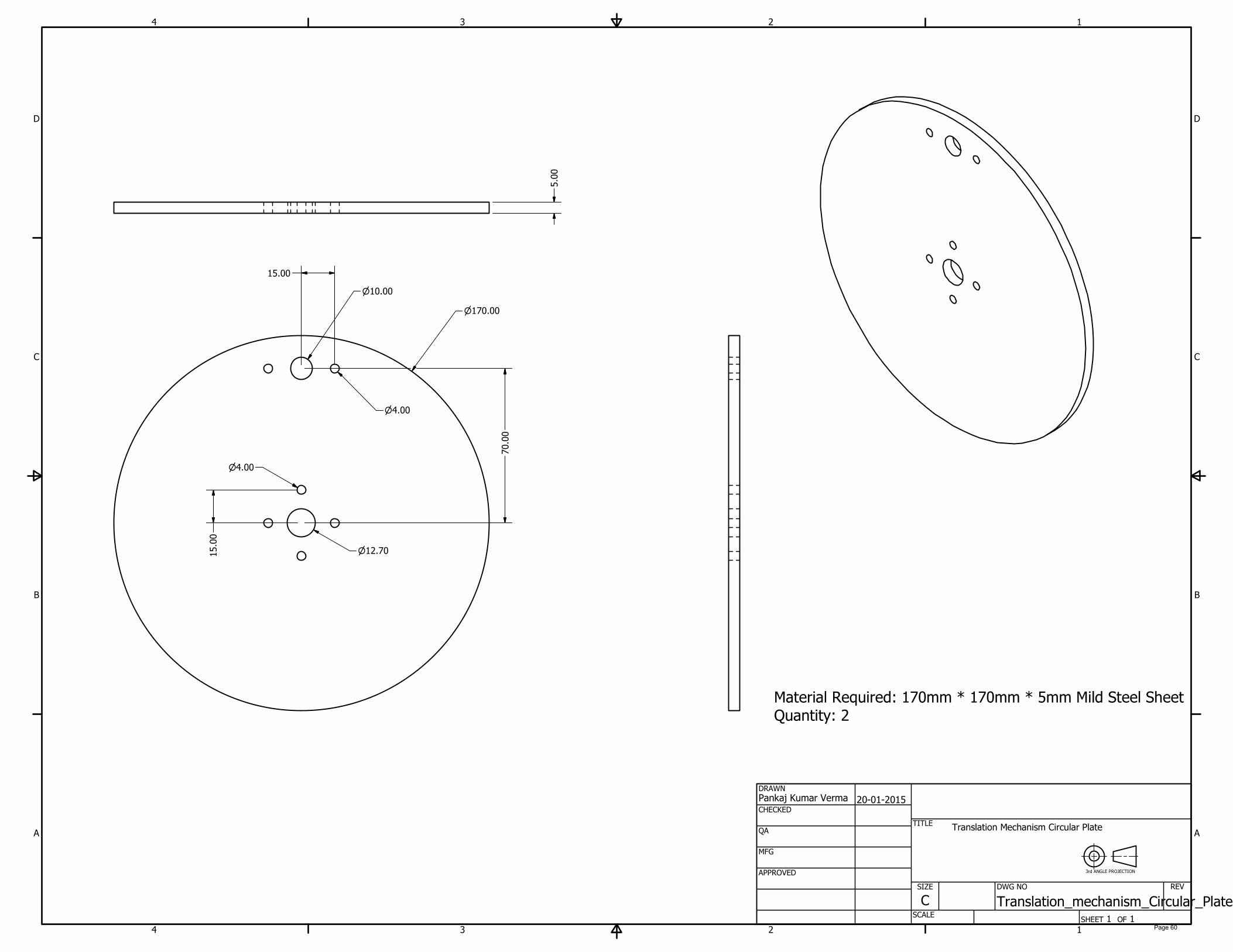
Translation Mechanism Circular Plate
3rd ANGLE PROJECTION
Material Required: 170mm * 170mm * 5mm Mild Steel Sheet
Quantity: 2
Page 60

1
1
2
2
3
3
4
4
A A
B B
C C
D D
SHEET 1 OF 1
DRAWN
CHECKED
QA
MFG
APPROVED
Pankaj Kumar Verma
20-01-2015
DWG NO
Translation_mechanism_Groove_rod
TITLE
SIZE
C
SCALE
REV
10.00
162.00
R3.00
20.00
170.00
Translation Mechanism Groove rod
3rd ANGLE PROJECTION
Material Required: 20mm * 10mm * 170 mm Mild Steel Flat Quantity: 1
Page 61
1
1
2
2
3
3
4
4
A A
B B
C C
D D
SHEET 1 OF 1
DRAWN
CHECKED
QA
MFG
APPROVED
Pankaj Kumar Verma
20-01-2015
DWG NO
Translation_mechanism_Hub1
TITLE
SIZE
C
SCALE
REV
12.70
22.00
40.00
15.00
4.00
15.00
10.00
R2.00
7.00
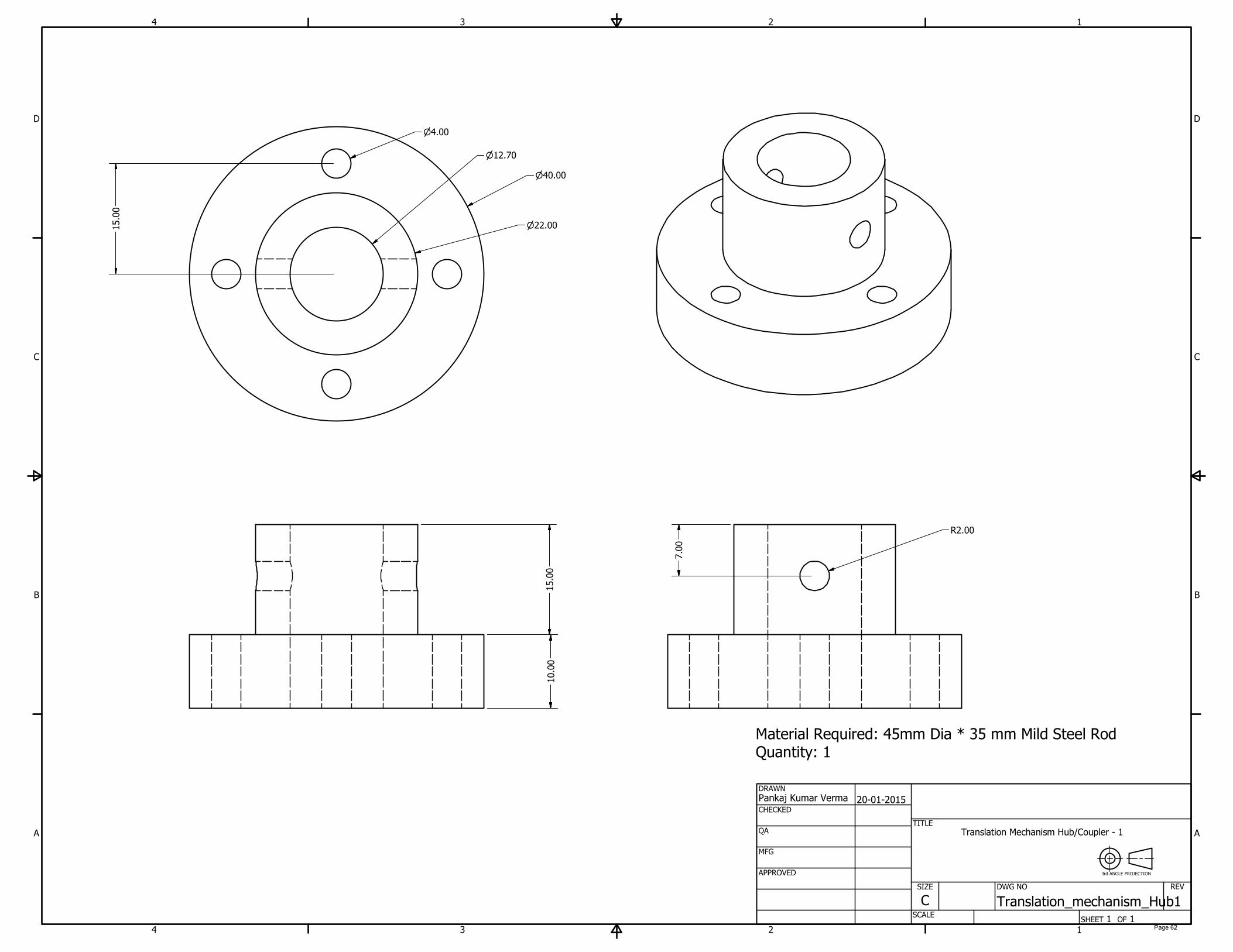
Translation Mechanism Hub/Coupler - 1
3rd ANGLE PROJECTION
Material Required: 45mm Dia * 35 mm Mild Steel Rod
Quantity: 1
Page 62
1
1
2
2
3
3
4
4
A A
B B
C C
D D
SHEET 1 OF 1
DRAWN
CHECKED
QA
MFG
APPROVED
Pankaj Kumar Verma
20-01-2015
DWG NO
Translation_mechanism_Hub2
TITLE
SIZE
C
SCALE
REV
40.00
18.00
10.00
4.00
15.00
R2.00
7.00
15.00
10.00
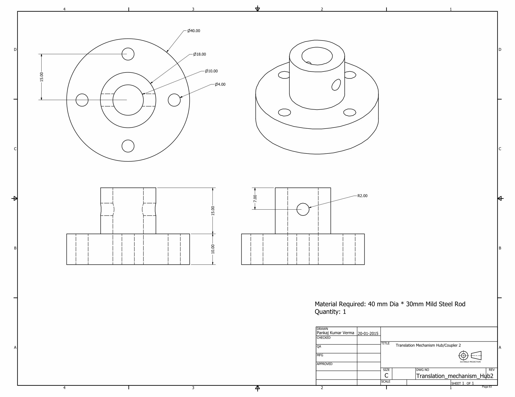
Translation Mechanism Hub/Coupler 2
3rd ANGLE PROJECTION
Material Required: 40 mm Dia * 30mm Mild Steel Rod
Quantity: 1
Page 63

1
1
2
2
3
3
4
4
A A
B B
C C
D D
SHEET 1 OF 1
DRAWN
CHECKED
QA
MFG
APPROVED
Pankaj Kumar Verma
20-01-2015
DWG NO
Translation_mechanism_Rod_6mm
TITLE
SIZE
C
SCALE
REV
10.00
50.00
27.00
R2.00
Translation Mechanism Rod 10 mm dia 50 mm lenght
3rd ANGLE PROJECTION
Material Required: 10mm Dia * 50mm Mild Steel Rod
Quantity: 1
Page 64
1
1
2
2
3
3
4
4
A A
B B
C C
D D
SHEET 1 OF 1
DRAWN
CHECKED
QA
MFG
APPROVED
Pankaj Kumar Verma
20-01-2015
DWG NO
Translation_mechanism_Rod_10mm
TITLE
SIZE
C
SCALE
REV
10.00
200.00
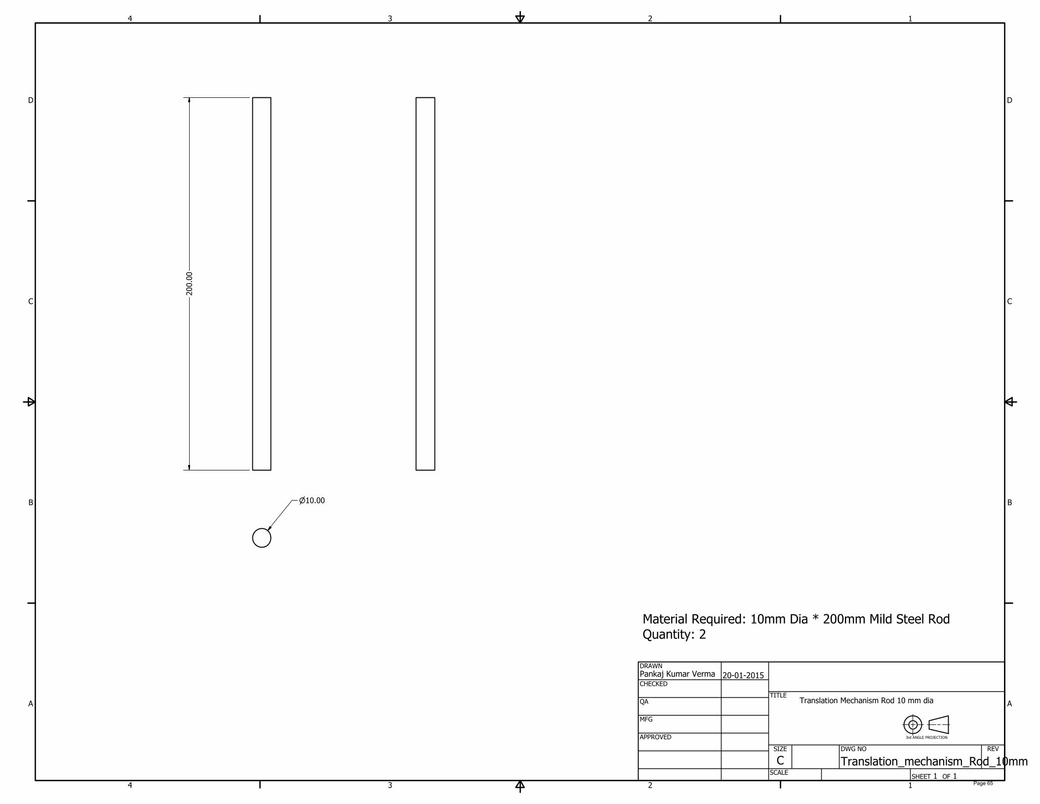
Translation Mechanism Rod 10 mm dia
3rd ANGLE PROJECTION
Material Required: 10mm Dia * 200mm Mild Steel Rod
Quantity: 2
Page 65

APPENDIX – 7
Isometric Drawing of Pulling Mechanism Assembly and Parts
Page 66

PARTS LIST
DESCRIPTIONPART NUMBERQTYITEM
Pulling_Mechanism_Angle21
Pulling_Sqaure_Rod12
Shaft_60mm13
Shaft_180mm14
1
1
2
2
3
3
4
4
A A
B B
C C
D D
SHEET 1 OF 1
DRAWN
CHECKED
QA
MFG
APPROVED
Pankaj Kumar Verma
20-01-2015
DWG NO
TITLE
SIZE
C
SCALE
REV
4
3
2
1
30.00
10.00
95.00
Pulling Mechanism
3rd ANGLE PROJECTION
Page 67
1
1
2
2
3
3
4
4
A A
B B
C C
D D
SHEET 1 OF 1
DRAWN
CHECKED
QA
MFG
APPROVED
Pankaj Kumar Verma
20-01-2015
DWG NO
Pulling_Mechanism_Angle
TITLE
SIZE
C
SCALE
REV
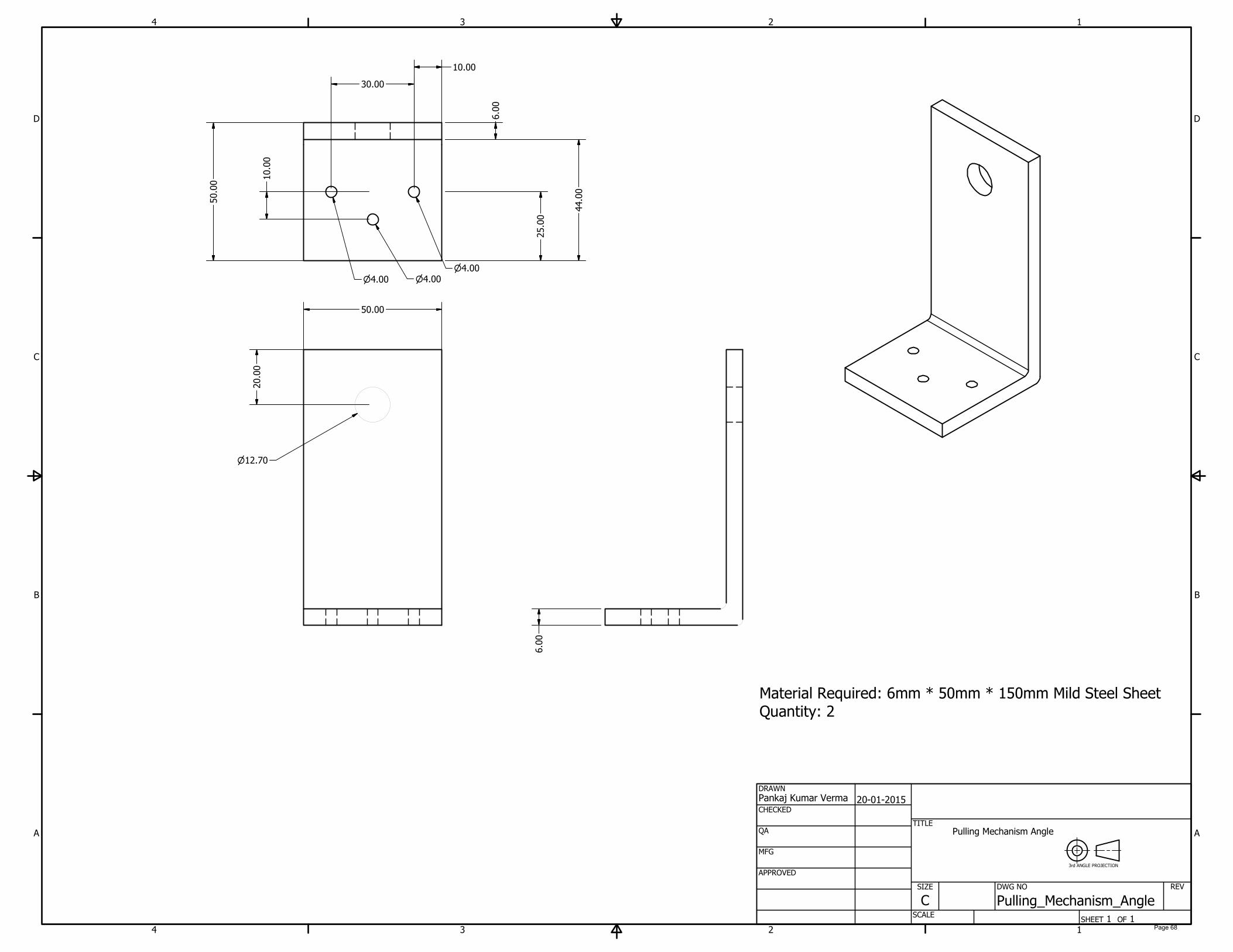
20.00
12.70
50.00
6.00
6.00
44.00
25.00
10.00
30.00
10.00
4.004.00
4.00
50.00
Pulling Mechanism Angle
3rd ANGLE PROJECTION
Material Required: 6mm * 50mm * 150mm Mild Steel Sheet
Quantity: 2
Page 68
1
1
2
2
3
3
4
4
A A
B B
C C
D D
SHEET 1 OF 1
DRAWN
CHECKED
QA
MFG
APPROVED
Pankaj Kumar Verma
20-01-2015
DWG NO
Pulling_Sqaure_Rod
TITLE
SIZE
C
SCALE
REV
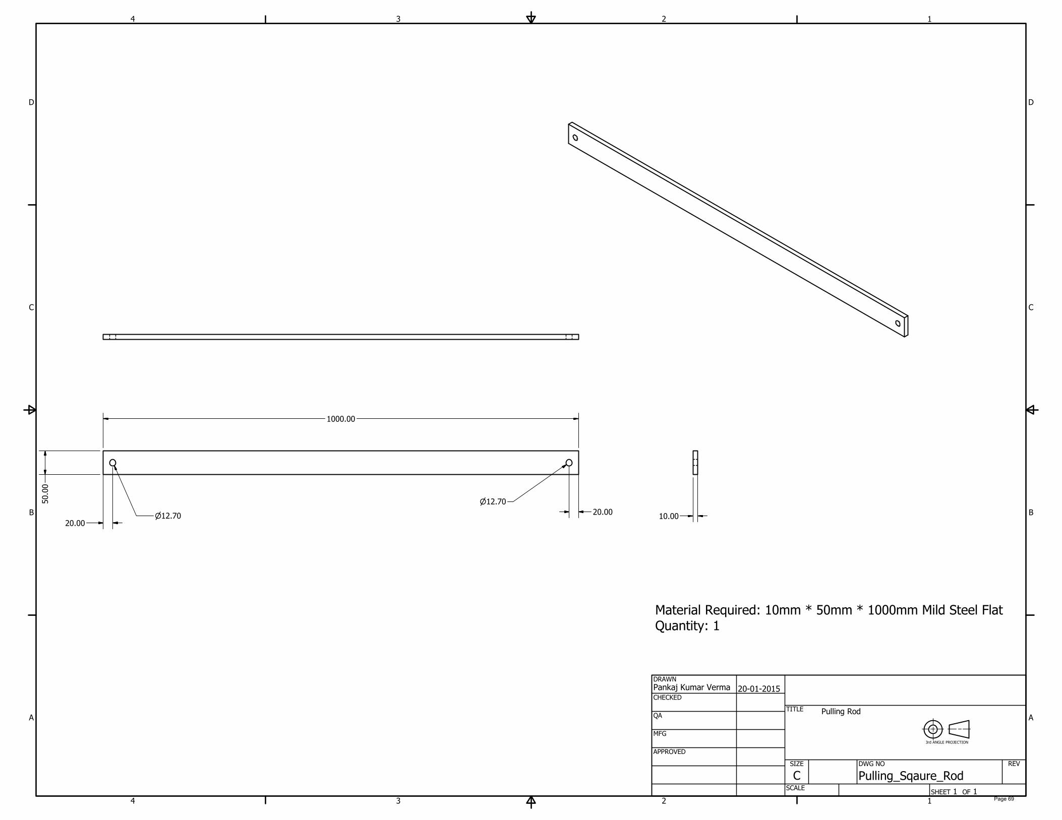
1000.00
50.00
20.00
12.70
20.00
12.7010.00
Pulling Rod
3rd ANGLE PROJECTION
Material Required: 10mm * 50mm * 1000mm Mild Steel Flat Quantity: 1
Page 69
1
1
2
2
3
3
4
4
A A
B B
C C
D D
SHEET 1 OF 1
DRAWN
CHECKED
QA
MFG
APPROVED
Pankaj Kumar Verma
20-01-2015
DWG NO
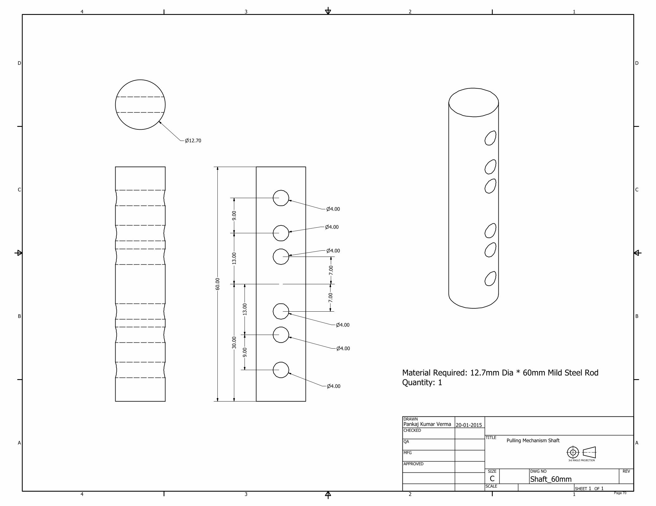
Shaft_60mm
TITLE
SIZE
C
SCALE
REV
30.00
7.00
7.00
13.00
13.00
9.00
9.00
4.00
4.00
4.00
4.00
4.00
4.00
60.00
12.70
Pulling Mechanism Shaft
3rd ANGLE PROJECTION
Material Required: 12.7mm Dia * 60mm Mild Steel Rod
Quantity: 1
Page 70

1
1
2
2
3
3
4
4
A A
B B
C C
D D
SHEET 1 OF 1
DRAWN
CHECKED
QA
MFG
APPROVED
Pankaj Kumar Verma
20-01-2015
DWG NO
Shaft_180mm
TITLE
SIZE
C
SCALE
REV
12.70
100.00
93.00
4.00
12.70
Pulling Shaft -2
3rd ANGLE PROJECTION
200.00
Material Required: 12.7mm Dia * 200mm Mild Steel Rod
Quantity: 1
Page 71
APPENDIX – 8
Isometric Drawing and Calculations of Gears
Page 72

PARTS LIST
DESCRIPTIONPART NUMBERQTYITEM
Spur Gear111
Spur Gear212
1
1
2
2
3
3
4
4
A A
B B
C C
D D
SHEET 1 OF 1
DRAWN
CHECKED
QA
MFG
APPROVED
Pankaj Kumar Verma
20-01-2015
DWG NO
TITLE
SIZE
C
SCALE
REV
72.00
2
1
Spur Gear Assembly
3rd ANGLE PROJECTION
Page 73
1
1
2
2
3
3
4
4
A A
B B
C C
D D
SHEET 1 OF 1
DRAWN
CHECKED
QA
MFG
APPROVED
Pankaj Kumar Verma
20-01-2015
DWG NO
Spur Gear22
TITLE
SIZE
C
SCALE
REV
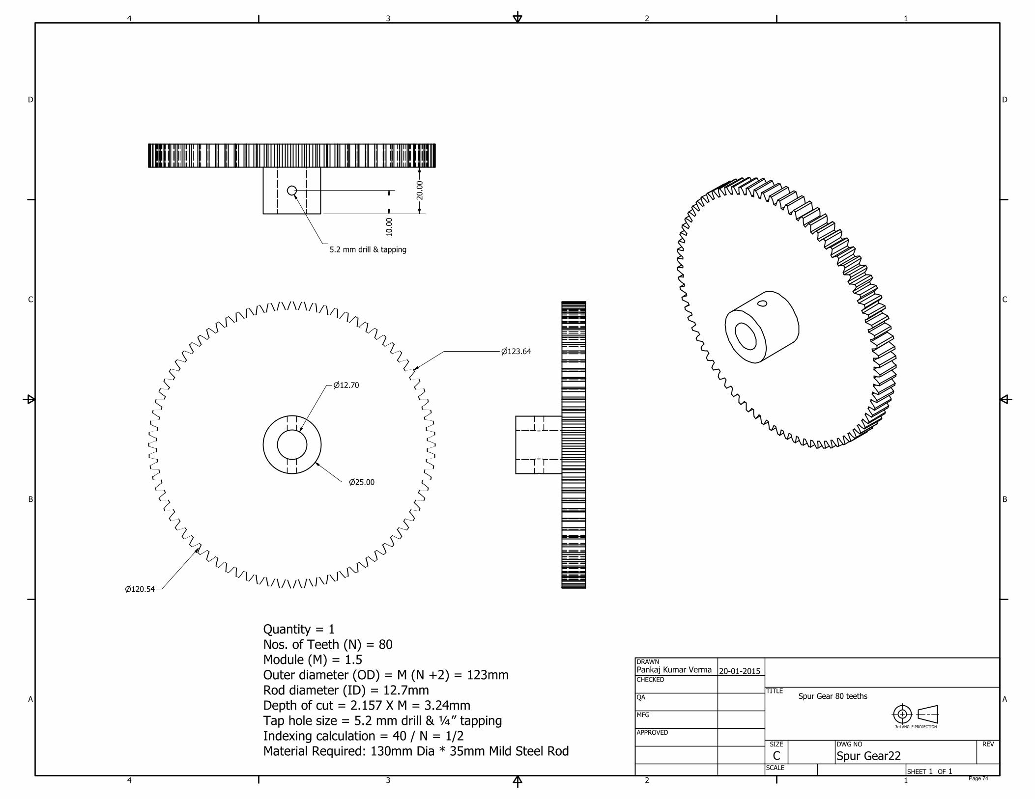
123.64
120.54
25.00
12.70
10.00
5.2 mm drill & tapping
20.00
Quantity = 1
Nos. of Teeth (N) = 80
Module (M) = 1.5
Outer diameter (OD) = M (N +2) = 123mm
Rod diameter (ID) = 12.7mm
Depth of cut = 2.157 X M = 3.24mm
Tap hole size = 5.2 mm drill & ¼” tapping
Indexing calculation = 40 / N = 1/2
Material Required: 130mm Dia * 35mm Mild Steel Rod
Spur Gear 80 teeths
3rd ANGLE PROJECTION
Page 74
1
1
2
2
3
3
4
4
A A
B B
C C
D D
SHEET 1 OF 1
DRAWN
CHECKED
QA
MFG
APPROVED
Pankaj Kumar Verma
20-01-2015
DWG NO
Spur Gear12
TITLE
SIZE
C
SCALE
REV
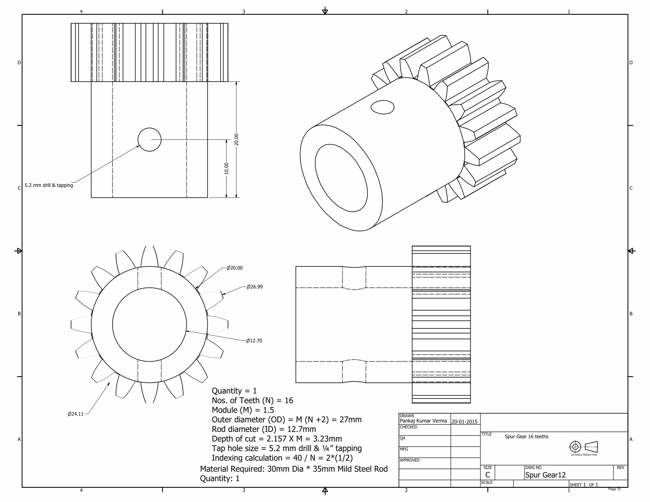
26.99
24.11
20.00
12.70
20.00
10.00
5.2 mm drill & tapping
Spur Gear 16 teeths
3rd ANGLE PROJECTION
Quantity = 1
Nos. of Teeth (N) = 16
Module (M) = 1.5
Outer diameter (OD) = M (N +2) = 27mm
Rod diameter (ID) = 12.7mm
Depth of cut = 2.157 X M = 3.23mm
Tap hole size = 5.2 mm drill & ¼” tapping
Indexing calculation = 40 / N = 2*(1/2)
Material Required: 30mm Dia * 35mm Mild Steel Rod
Quantity: 1
Page 75
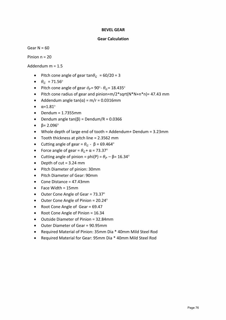
BEVEL GEAR
Gear Calculation
Gear N = 60
Pinion n = 20
Addendum m = 1.5
Pitch cone angle of gear tan𝜃𝐺 = 60/20 = 3
𝜃𝐺 = 71.56
Pitch cone angle of gear 𝑃= 90- 𝜃𝐺= 18.435
Pitch cone radius of gear and pinion=m/2*sqrt(N*N+n*n)= 47.43 mm
Addendum angle tan(α) = m/r = 0.0316mm
α=1.81
Dendum = 1.7355mm
Dendum angle tan(β) = Dendum/R = 0.0366
β= 2.096
Whole depth of large end of tooth = Addendum+ Dendum = 3.23mm
Tooth thickness at pitch line = 2.3562 mm
Cutting angle of gear = 𝜃𝐺 - β = 69.464
Force angle of gear = 𝜃𝐺+ α = 73.37
Cutting angle of pinion = phi(P) = 𝜃𝑃 – β= 16.34
Depth of cut = 3.24 mm
Pitch Diameter of pinion: 30mm
Pitch Diameter of Gear: 90mm
Cone Distance = 47.43mm
Face Width = 15mm
Outer Cone Angle of Gear = 73.37
Outer Cone Angle of Pinion = 20.24
Root Cone Angle of Gear = 69.47
Root Cone Angle of Pinion = 16.34
Outside Diameter of Pinion = 32.84mm
Outer Diameter of Gear = 90.95mm
Required Material of Pinion: 35mm Dia * 40mm Mild Steel Rod
Required Material for Gear: 95mm Dia * 40mm Mild Steel Rod
Page 76

1
1
2
2
3
3
4
4
A A
B B
C C
D D
SHEET 1 OF 1
DRAWN
CHECKED
QA
MFG
APPROVED
Pankaj Kumar Verma
20-01-2015
DWG NO
TITLE
SIZE
C
SCALE
REV
Bevel Gear Assembly
3rd ANGLE PROJECTION
Page 77
PARTS LIST
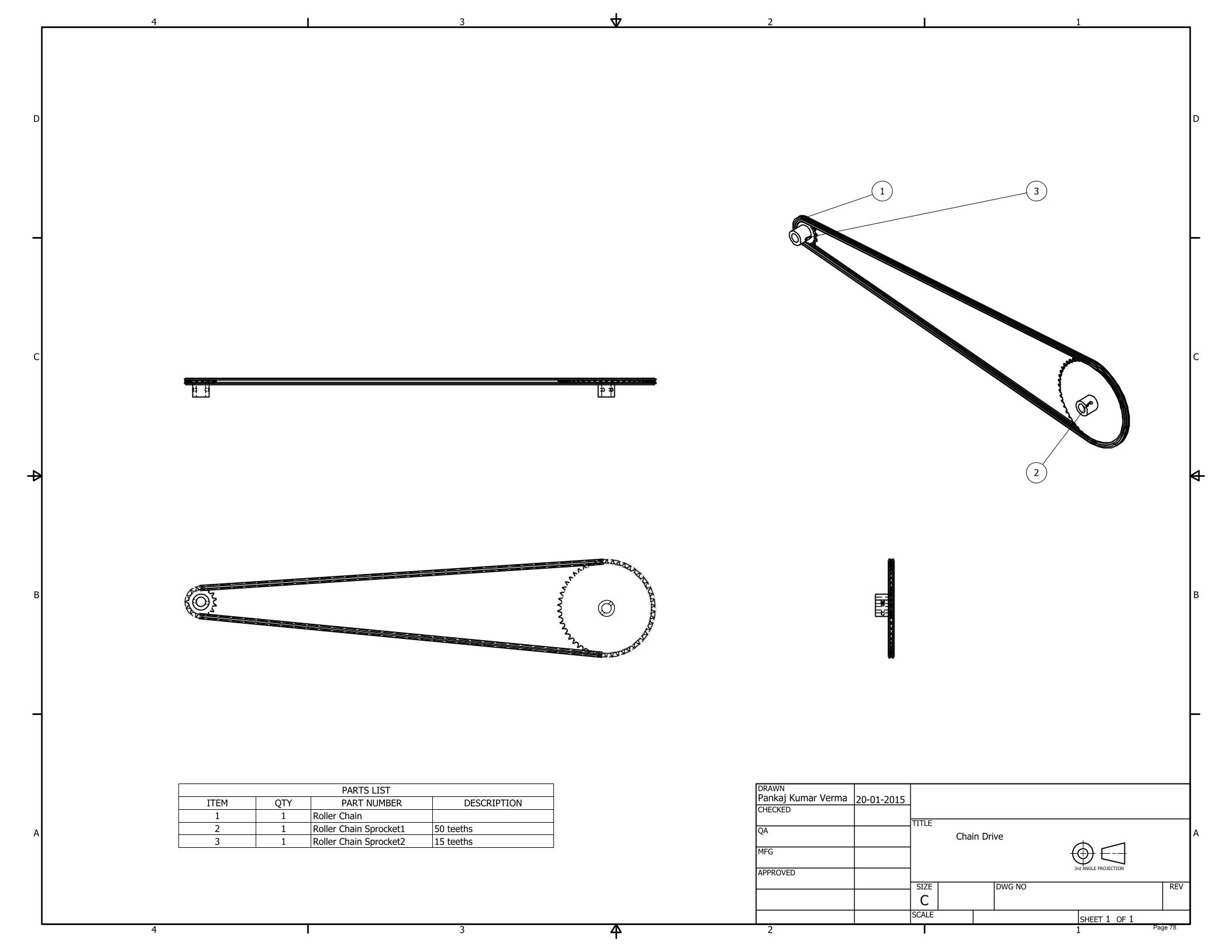
DESCRIPTIONPART NUMBERQTYITEM
Roller Chain11
50 teethsRoller Chain Sprocket112
15 teethsRoller Chain Sprocket213
1
1
2
2
3
3
4
4
A A
B B
C C
D D
SHEET 1 OF 1
DRAWN
CHECKED
QA
MFG
APPROVED
Pankaj Kumar Verma
20-01-2015
DWG NO
TITLE
SIZE
C
SCALE
REV
31
2
Chain Drive
3rd ANGLE PROJECTION
Page 78
1
1
2
2
3
3
4
4
A A
B B
C C
D D
SHEET 1 OF 1
DRAWN
CHECKED
QA
MFG
APPROVED
Pankaj Kumar Verma
21-01-2015
DWG NO
TITLE
SIZE
C
SCALE
REV
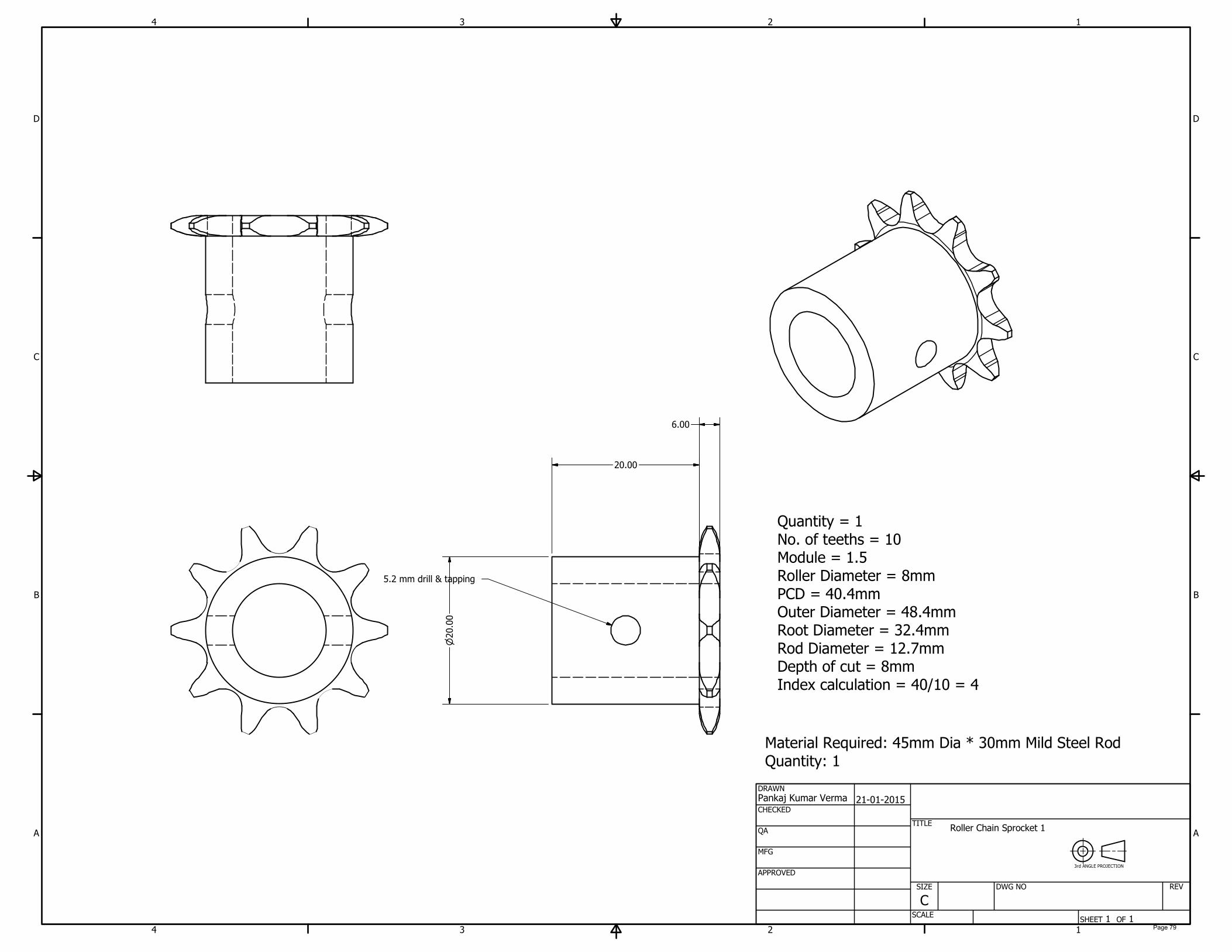
Quantity = 1
No. of teeths = 10
Module = 1.5
Roller Diameter = 8mm
PCD = 40.4mm
Outer Diameter = 48.4mm
Root Diameter = 32.4mm
Rod Diameter = 12.7mm
Depth of cut = 8mm
Index calculation = 40/10 = 4
5.2 mm drill & tapping
20.00
20.00
6.00
Material Required: 45mm Dia * 30mm Mild Steel Rod
Quantity: 1
Roller Chain Sprocket 1
3rd ANGLE PROJECTION
Page 79

APPENDIX – 9
Isometric Drawing of Miscellaneous Parts
Page 80
1
1
2
2
3
3
4
4
A A
B B
C C
D D
SHEET 1 OF 1
DRAWN
CHECKED
QA
MFG
APPROVED
Pankaj Kumar Verma
21-01-2015
DWG NO
TITLE
SIZE
C
SCALE
REV
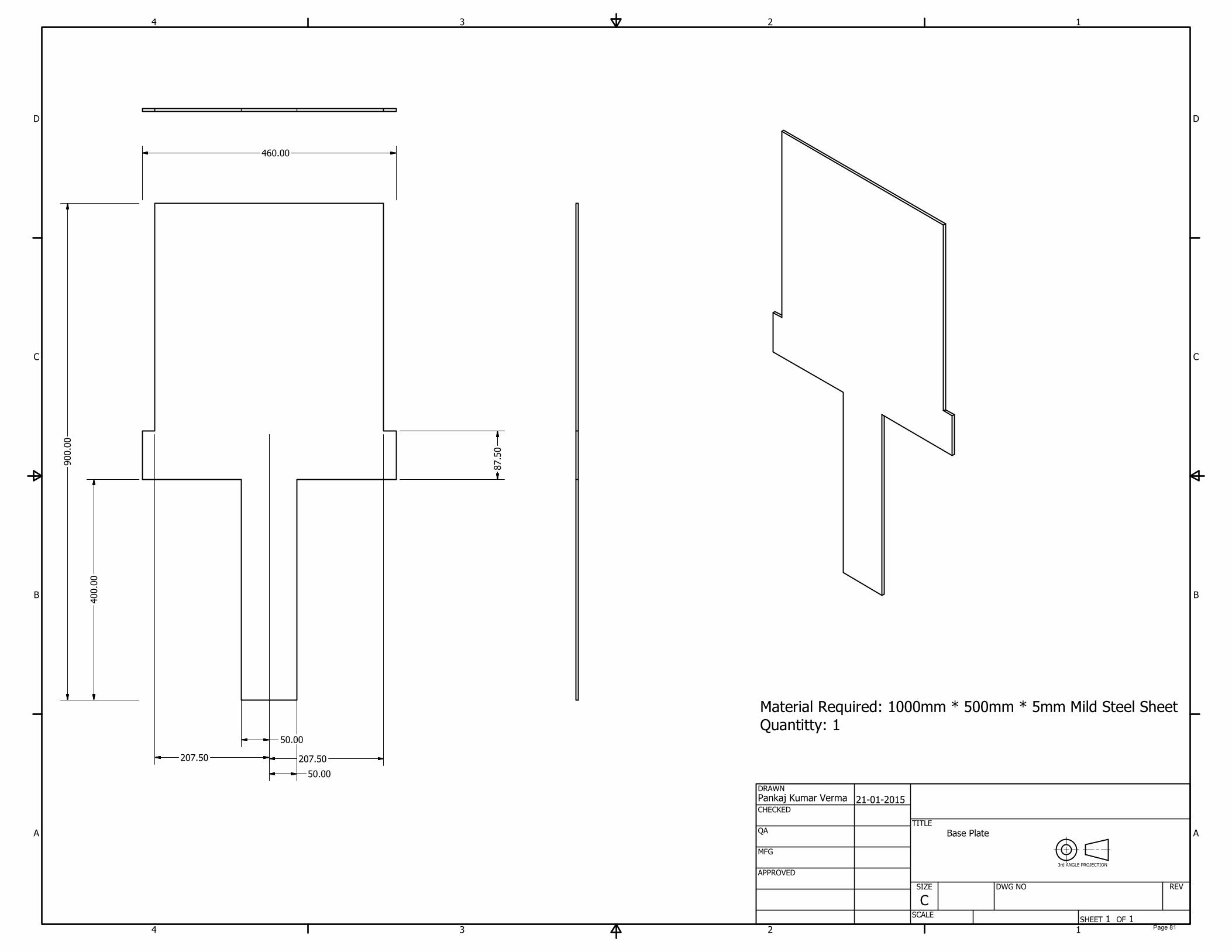
460.00
900.00
400.00
50.00
50.00
87.50
207.50
207.50
Material Required: 1000mm * 500mm * 5mm Mild Steel Sheet
Quantitty: 1
Base Plate
3rd ANGLE PROJECTION
Page 81
1
1
2
2
3
3
4
4
A A
B B
C C
D D
SHEET 1 OF 1
DRAWN
CHECKED
QA
MFG
APPROVED
Pankaj Kumar Verma
20-01-2015
DWG NO
Bevel_Gear_Support
TITLE
SIZE
C
SCALE
REV
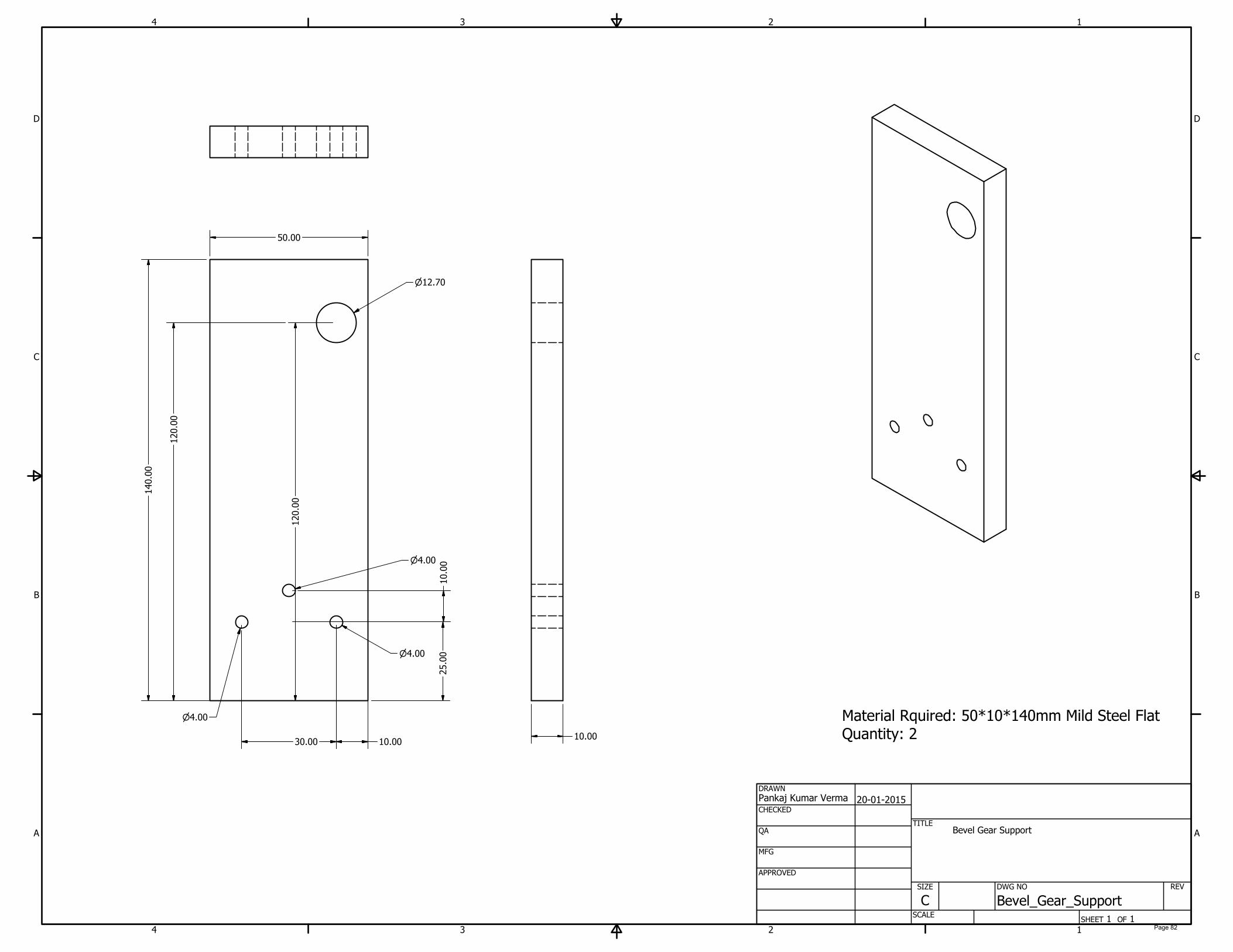
50.00
140.00
120.00
120.00
12.70
25.00
10.0030.00
10.00
4.00
4.00
4.00
10.00
Bevel Gear Support
Material Rquired: 50*10*140mm Mild Steel Flat Quantity: 2
Page 82
1
1
2
2
3
3
4
4
A A
B B
C C
D D
SHEET 1 OF 1
DRAWN
CHECKED
QA
MFG
APPROVED
Pankaj Kumar Verma
21-01-2015
DWG NO
TITLE
SIZE
C
SCALE
REV
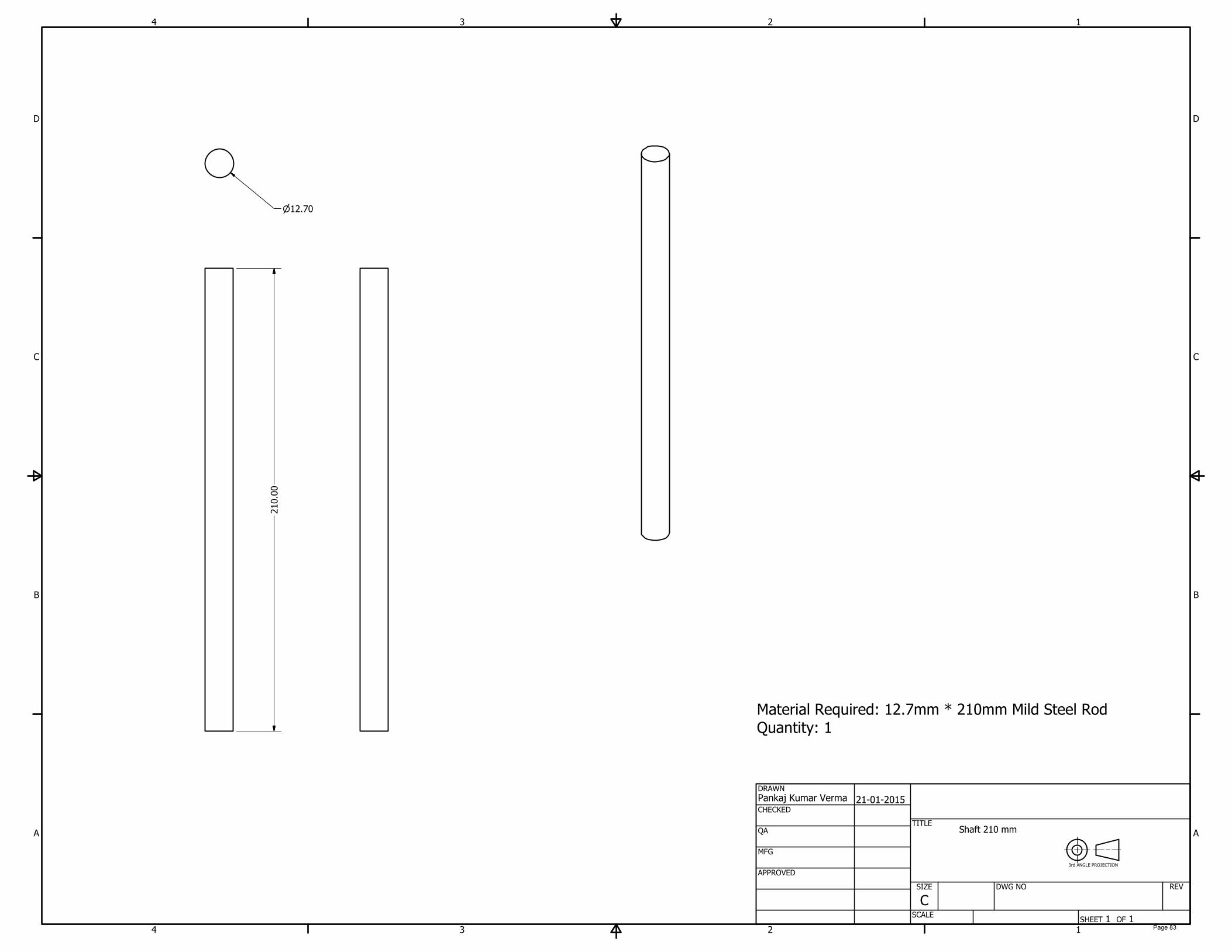
210.00
12.70
Material Required: 12.7mm * 210mm Mild Steel Rod
Quantity: 1
Shaft 210 mm
3rd ANGLE PROJECTION
Page 83
1
1
2
2
3
3
4
4
A A
B B
C C
D D
SHEET 1 OF 1
DRAWN
CHECKED
QA
MFG
APPROVED
Pankaj Kumar Verma
20-01-2015
DWG NO
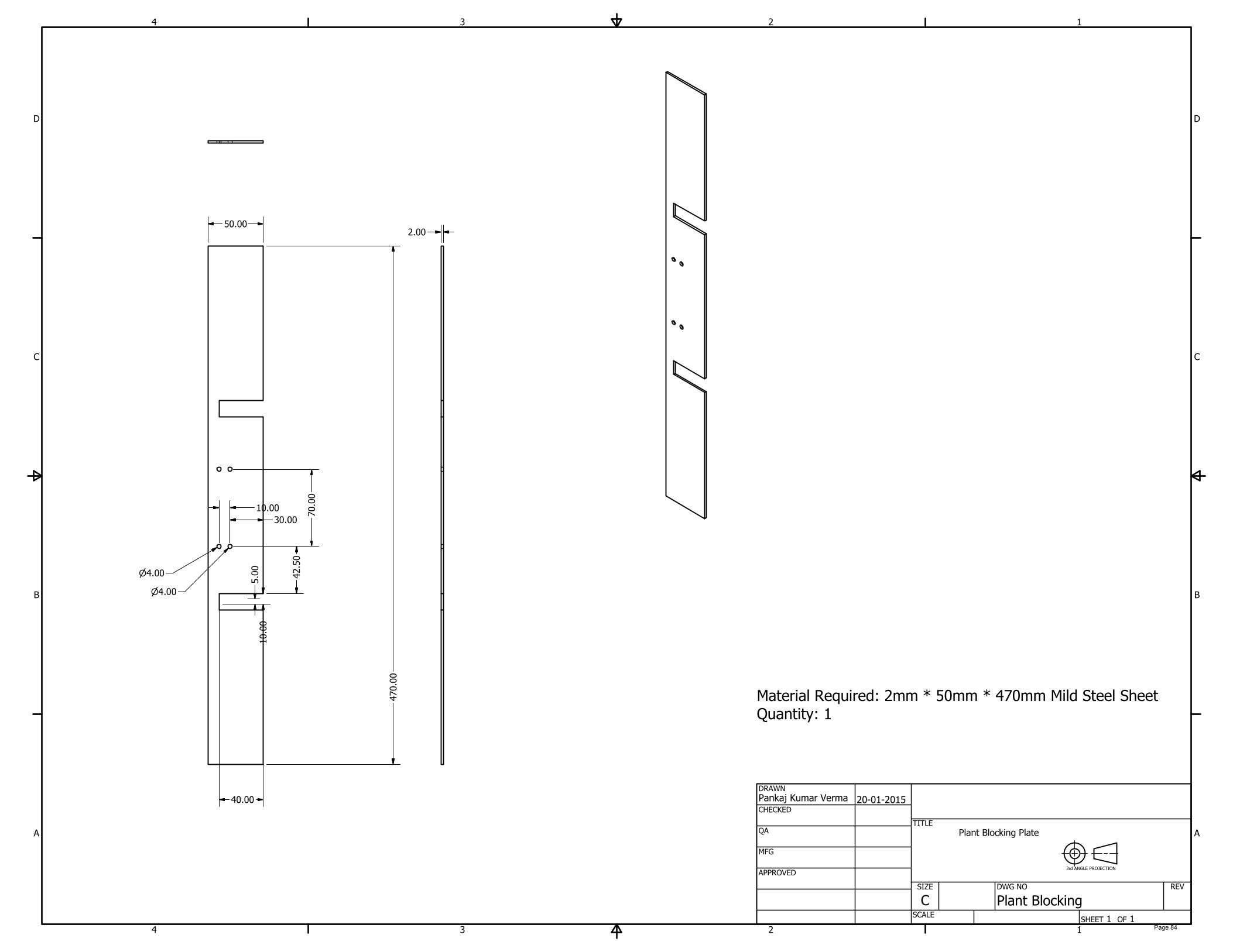
Plant Blocking
TITLE
SIZE
C
SCALE
REV
5.00
40.00
10.00
42.50
30.00
10.00
4.00
4.00
70.00
470.00
50.00
2.00
Plant Blocking Plate
3rd ANGLE PROJECTION
Material Required: 2mm * 50mm * 470mm Mild Steel Sheet
Quantity: 1
Page 84
1
1
2
2
3
3
4
4
A A
B B
C C
D D
SHEET 1 OF 1
DRAWN
CHECKED
QA
MFG
APPROVED
Pankaj Kumar Verma
20-01-2015
DWG NO
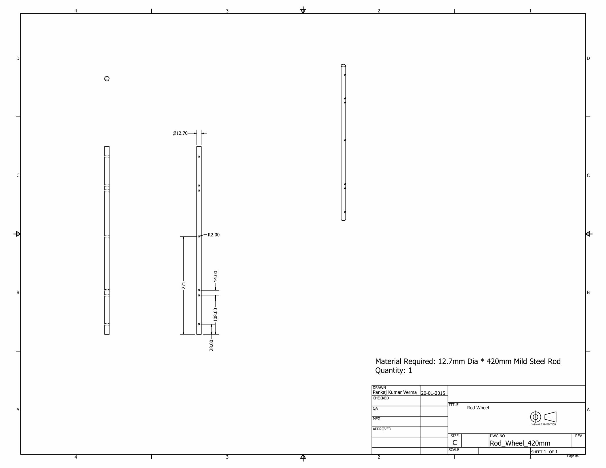
Rod_Wheel_420mm
TITLE
SIZE
C
SCALE
REV
28.00
108.00
14.00
271
12.70
R2.00
Rod Wheel
3rd ANGLE PROJECTION
Material Required: 12.7mm Dia * 420mm Mild Steel Rod
Quantity: 1
Page 85

1
1
2
2
3
3
4
4
A A
B B
C C
D D
SHEET 1 OF 1
DRAWN
CHECKED
QA
MFG
APPROVED
Pankaj Kumar Verma
21-01-2015
DWG NO
TITLE
SIZE
C
SCALE
REV
12.70
200.00
Material Required: 12.7mm Dia * 200mm Mild Steel Rod
Quantity: 1
Shaft 200mm lenght
3rd ANGLE PROJECTION
Page 86
1
1
2
2
3
3
4
4
A A
B B
C C
D D
SHEET 1 OF 1
DRAWN
CHECKED
QA
MFG
APPROVED
Pankaj Kumar Verma
21-01-2015
DWG NO
TITLE
SIZE
C
SCALE
REV
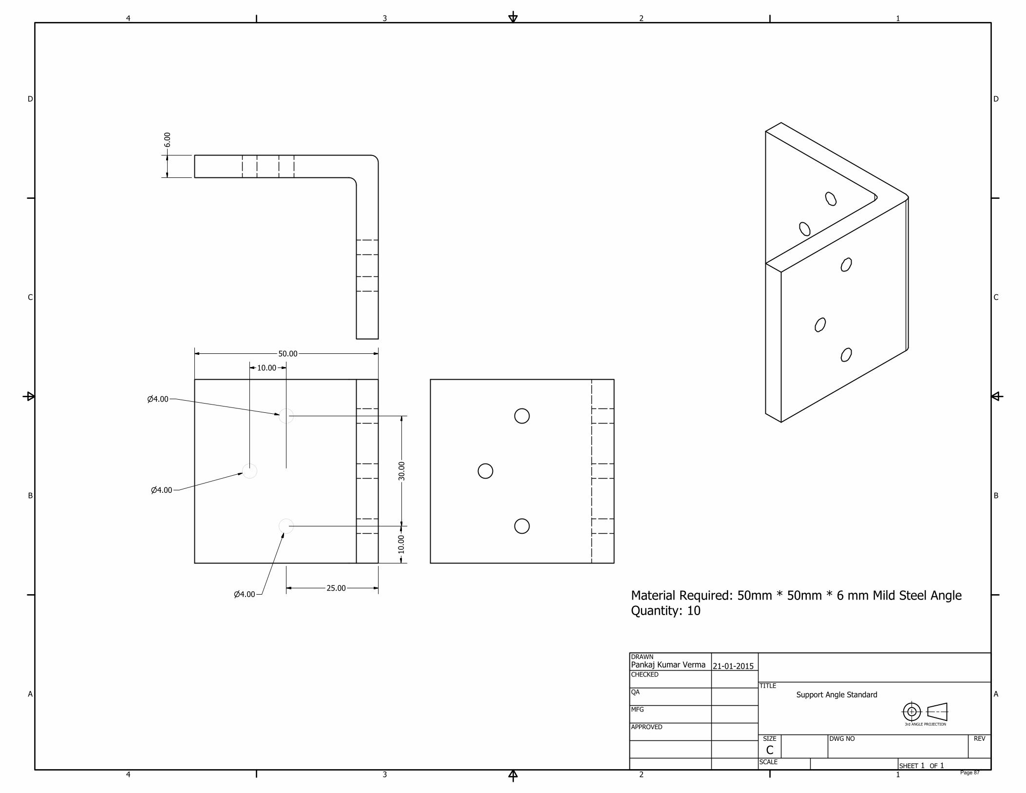
25.00
10.00
30.00
4.00
4.00
10.00
4.00
50.00
6.00
Material Required: 50mm * 50mm * 6 mm Mild Steel Angle
Quantity: 10
Support Angle Standard
3rd ANGLE PROJECTION
Page 87

1
1
2
2
3
3
4
4
A A
B B
C C
D D
SHEET 1 OF 1
DRAWN
CHECKED
QA
MFG
APPROVED
Pankaj Kumar Verma
21-01-2015
DWG NO
TITLE
SIZE
C
SCALE
REV
25.00
140.00
10.00
30.00
5.00
10.00
4.00
4.00
6.00
Material Required: 140mm *25mm * 6mm Mild Steel Flat Quantity: 1
Tray Power Transmission Bar
3rd ANGLE PROJECTION
Page 88
1
1
2
2
3
3
4
4
A A
B B
C C
D D
SHEET 1 OF 1
DRAWN
CHECKED
QA
MFG
APPROVED
Pankaj Kumar Verma
20-01-2015
DWG NO
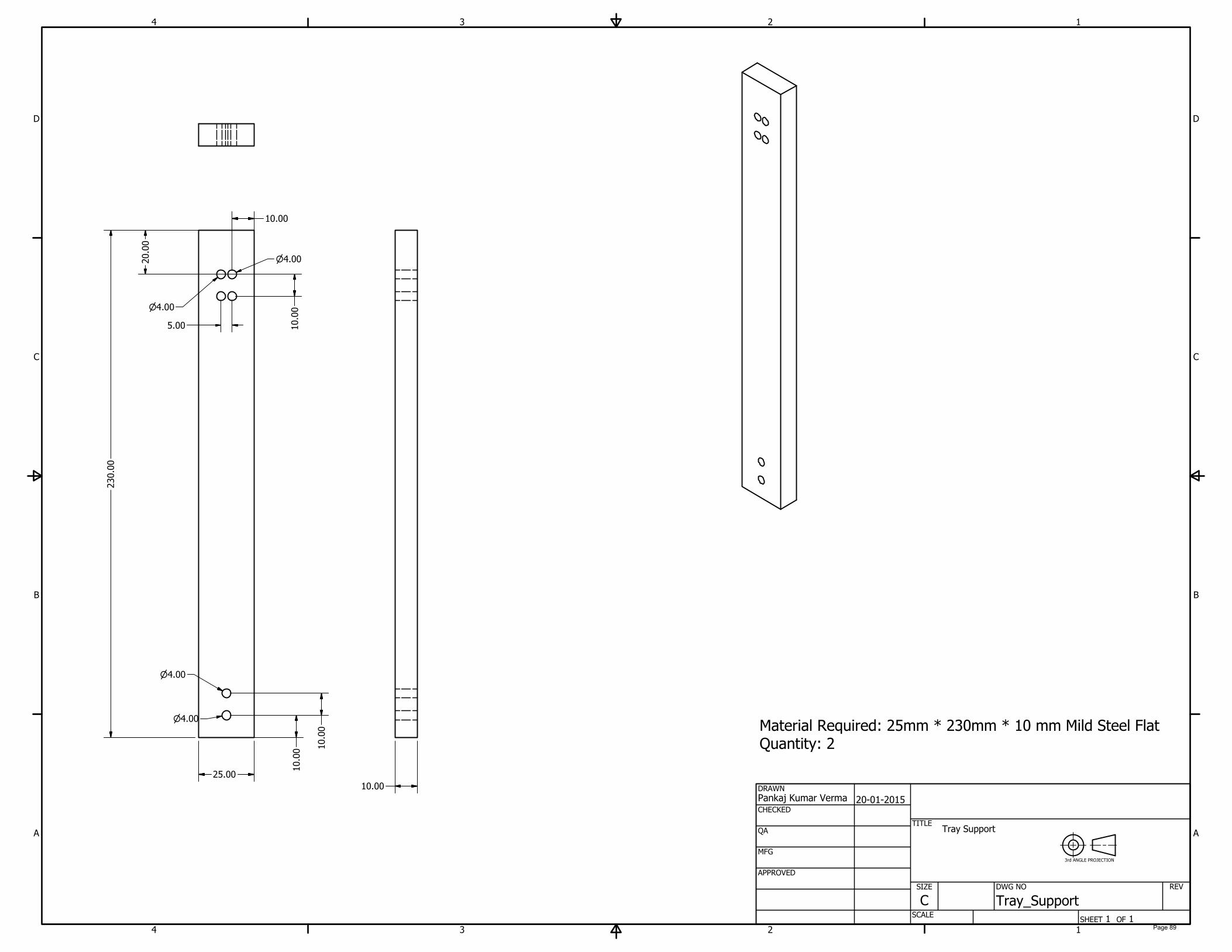
Tray_Support
TITLE
SIZE
C
SCALE
REV
25.00
230.00
20.00
10.00
4.00
4.00
10.00
10.00
4.00
4.00
5.00
10.00
10.00
Tray Support
3rd ANGLE PROJECTION
Material Required: 25mm * 230mm * 10 mm Mild Steel Flat Quantity: 2
Page 89
1
1
2
2
3
3
4
4
A A
B B
C C
D D
SHEET 1 OF 1
DRAWN
CHECKED
QA
MFG
APPROVED
Pankaj Kumar Verma
20-01-2015
DWG NO
Tray_Support_Angle
TITLE
SIZE
C
SCALE
REV
50.00
6.00
44.00
44.00
R2.00
10.00
10.00
30.00
5.00
10.00
4.00
4.00
25.00
Tray Supporting Wall Angle
3rd ANGLE PROJECTION
Material Required: 50mm * 50mm * 6mm Mild Steel Angle
Quantity: 3
Page 90
1
1
2
2
3
3
4
4
A A
B B
C C
D D
SHEET 1 OF 1
DRAWN
CHECKED
QA
MFG
APPROVED
Pankaj Kumar Verma
20-01-2015
DWG NO
Tray_Supporting_Bar
TITLE
SIZE
C
SCALE
REV
25.00
10.0030.00
10.00
4.00
4.00
4.00
330.00
50.00
10.00
Tray Supporting Bar
3rd ANGLE PROJECTION
Material Required: 330mm * 50mm * 10mm Mild Steel Flat Quantity: 2
Page 91
1
1
2
2
3
3
4
4
A A
B B
C C
D D
SHEET 1 OF 1
DRAWN
CHECKED
QA
MFG
APPROVED
Pankaj Kumar Verma
20-01-2015
DWG NO
Tray_Supporting_Bar_10mm
TITLE
SIZE
C
SCALE
REV
50.00
140.00
120.00
10.00
25.00
10.0030.00
4.00
4.00
4.00
10.00
Tray Supporting Bar
3rd ANGLE PROJECTION
Material Required: 140mm * 50mm * 10mm Mild Steel Flat Quantity: 2
Page 92

1
1
2
2
3
3
4
4
A A
B B
C C
D D
SHEET 1 OF 1
DRAWN
CHECKED
QA
MFG
APPROVED
Pankaj Kumar Verma
20-01-2015
DWG NO
Wheel_Support
TITLE
SIZE
C
SCALE
REV
140.00
50.00
120.00
12.70
25.00
10.00 30.00
10.00
4.00
4.00
4.00
10.00
Wheel Support
3rd ANGLE PROJECTION
Material Required: 140mm * 50mm * 10mm Mild Steel Flat Quantity: 4
Page 93
APPENDIX – 10
COST ANALYSIS
Page 94
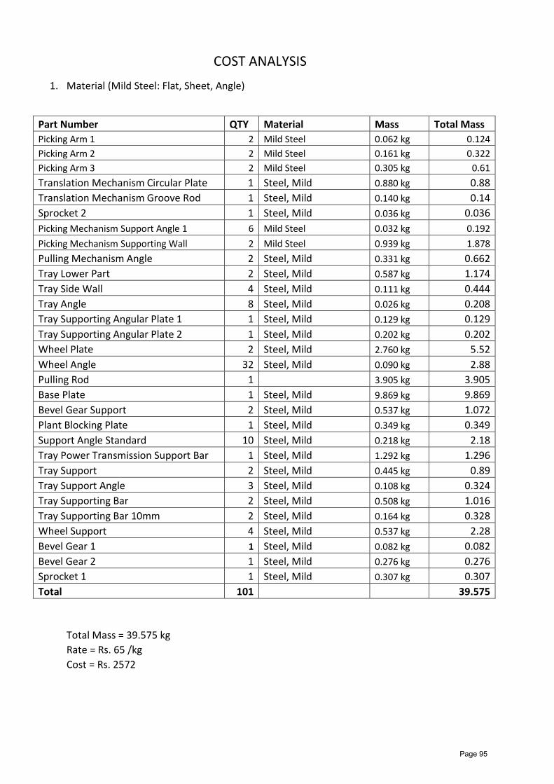
COST ANALYSIS 1. Material (Mild Steel: Flat, Sheet, Angle)
Part Number QTY Material Mass Total Mass Picking Arm 1 2 Mild Steel 0.062 kg 0.124 Picking Arm 2 2 Mild Steel 0.161 kg 0.322 Picking Arm 3 2 Mild Steel 0.305 kg 0.61 Translation Mechanism Circular Plate 1 Steel, Mild 0.880 kg 0.88 Translation Mechanism Groove Rod 1 Steel, Mild 0.140 kg 0.14 Sprocket 2 1 Steel, Mild 0.036 kg 0.036 Picking Mechanism Support Angle 1 6 Mild Steel 0.032 kg 0.192 Picking Mechanism Supporting Wall 2 Mild Steel 0.939 kg 1.878 Pulling Mechanism Angle 2 Steel, Mild 0.331 kg 0.662 Tray Lower Part 2 Steel, Mild 0.587 kg 1.174 Tray Side Wall 4 Steel, Mild 0.111 kg 0.444 Tray Angle 8 Steel, Mild 0.026 kg 0.208 Tray Supporting Angular Plate 1 1 Steel, Mild 0.129 kg 0.129 Tray Supporting Angular Plate 2 1 Steel, Mild 0.202 kg 0.202 Wheel Plate 2 Steel, Mild 2.760 kg 5.52 Wheel Angle 32 Steel, Mild 0.090 kg 2.88 Pulling Rod 1 3.905 kg 3.905 Base Plate 1 Steel, Mild 9.869 kg 9.869 Bevel Gear Support 2 Steel, Mild 0.537 kg 1.072 Plant Blocking Plate 1 Steel, Mild 0.349 kg 0.349 Support Angle Standard 10 Steel, Mild 0.218 kg 2.18 Tray Power Transmission Support Bar 1 Steel, Mild 1.292 kg 1.296 Tray Support 2 Steel, Mild 0.445 kg 0.89 Tray Support Angle 3 Steel, Mild 0.108 kg 0.324 Tray Supporting Bar 2 Steel, Mild 0.508 kg 1.016 Tray Supporting Bar 10mm 2 Steel, Mild 0.164 kg 0.328 Wheel Support 4 Steel, Mild 0.537 kg 2.28 Bevel Gear 1 1 Steel, Mild 0.082 kg 0.082 Bevel Gear 2 1 Steel, Mild 0.276 kg 0.276 Sprocket 1 1 Steel, Mild 0.307 kg 0.307 Total 101 39.575
Total Mass = 39.575 kg Rate = Rs. 65 /kg Cost = Rs. 2572
Page 95
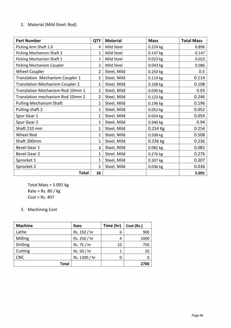
2. Material (Mild Steel: Rod)
Part Number QTY Material Mass Total Mass Picking Arm Shaft 1.0 4 Mild Steel 0.224 kg 0.896 Picking Mechanism Shaft 2 1 Mild Steel 0.147 kg 0.147 Picking Mechanism Shaft 1 1 Mild Steel 0.023 kg 0.023 Picking Mechanism Coupler 2 Mild Steel 0.043 kg 0.086 Wheel Coupler 2 Steel, Mild 0.250 kg 0.5 Translation Mechanism Coupler 1 1 Steel, Mild 0.114 kg 0.114 Translation Mechanism Coupler 2 1 Steel, Mild 0.108 kg 0.108 Translation Mechanism Rod 10mm 1 1 Steel, Mild 0.030 kg 0.03 Translation mechanism Rod 10mm 2 2 Steel, Mild 0.123 kg 0.246 Pulling Mechanism Shaft 1 Steel, Mild 0.196 kg 0.196 Pulling shaft 2 1 Steel, Mild 0.052 kg 0.052 Spur Gear 1 1 Steel, Mild 0.054 kg 0.054 Spur Gear 2 1 Steel, Mild 0.940 kg 0.94 Shaft 210 mm 1 Steel, Mild 0.254 Kg 0.254 Wheel Rod 1 Steel, Mild 0.508 kg 0.508 Shaft 200mm 1 Steel, Mild 0.236 kg 0.236 Bevel Gear 1 1 Steel, Mild 0.082 kg 0.082 Bevel Gear 2 1 Steel, Mild 0.276 kg 0.276 Sprocket 1 1 Steel, Mild 0.307 kg 0.307 Sprocket 2 1 Steel, Mild 0.036 kg 0.036
Total 26 5.091 Total Mass = 5.091 kg Rate = Rs. 80 / kg Cost = Rs. 407
3. Machining Cost
Machine Rate Time (hr) Cost (Rs.) Lathe Rs. 150 / hr 6 900 Milling Rs. 250 / hr 4 1000 Drilling Rs. 75 / hr 10 750 Cutting Rs. 50 / hr 1 50 CNC Rs. 1200 / hr 0 0
Total 2700
Page 96
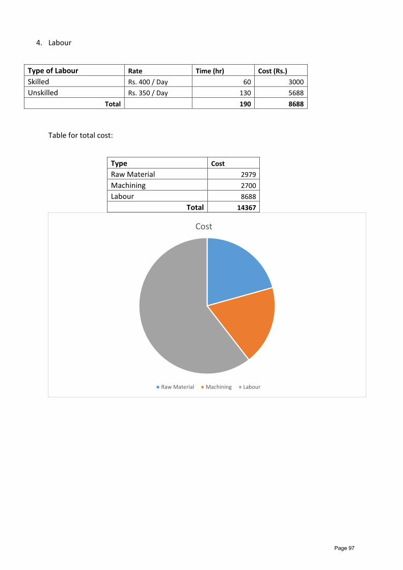
4. Labour
Type of Labour Rate Time (hr) Cost (Rs.) Skilled Rs. 400 / Day 60 3000 Unskilled Rs. 350 / Day 130 5688
Total 190 8688 Table for total cost:
Type Cost Raw Material 2979 Machining 2700 Labour 8688
Total 14367
Cost
Raw Material Machining Labour
Page 97
Weakness of the device 1. The planting unit is not much robust. 2. The angle at which the tray is inclined is very high.
Suggested Improvements 1. A more robust planting unit can be fabricated, with help of iteration of the different
types of heads of the Planting Arm 3. 2. Multiple machines can be used by connecting the in a line to a tractor. This will
increase the no. of rows of transplantation and decrease the labour cost.