basic nc and cnc - home.iitk.ac.inhome.iitk.ac.in/~jrkumar/download/me761a_lecture-4 cnc.pdf ·...
TRANSCRIPT
Dr. J. Ramkumar
Professor, Department of Mechanical Engineering
Micro machining Lab, I.I.T. Kanpur
Micro machining Lab, I.I.T. Kanpur
Basic NC and CNC
Outline
1. Introduction to CNC machine
2. Component and Function of CNC
3. Coordinate System

1.Introduction to CNC machine
CNC = Computerized Numerical Control
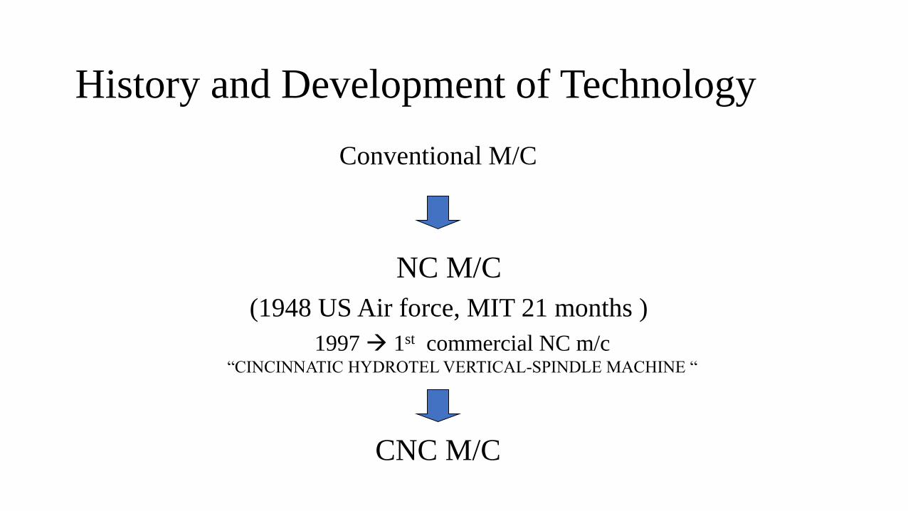
History and Development of Technology
Conventional M/C
NC M/C
(1948 US Air force, MIT 21 months )
CNC M/C
1997 → 1st commercial NC m/c “CINCINNATIC HYDROTEL VERTICAL-SPINDLE MACHINE “
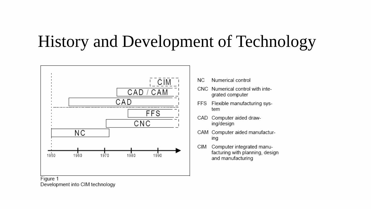
History and Development of Technology
Conventional vs. CNC machine
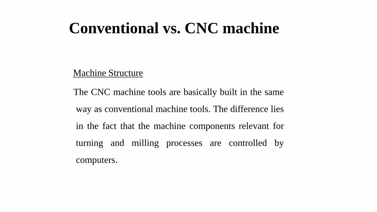
Machine Structure
The CNC machine tools are basically built in the same
way as conventional machine tools. The difference lies
in the fact that the machine components relevant for
turning and milling processes are controlled by
computers.

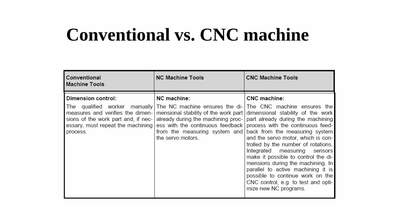
Conventional vs. CNC machine Function
Conventional vs. CNC machine
Conventional vs. CNC machine
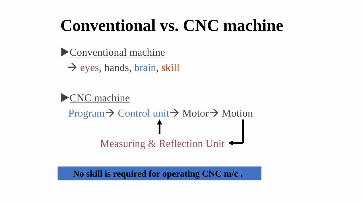
Conventional machine
→ eyes, hands, brain, skill
CNC machine
Program→ Control unit→Motor→Motion
Measuring & Reflection Unit
No skill is required for operating CNC m/c .

Conventional machine
CNC machine
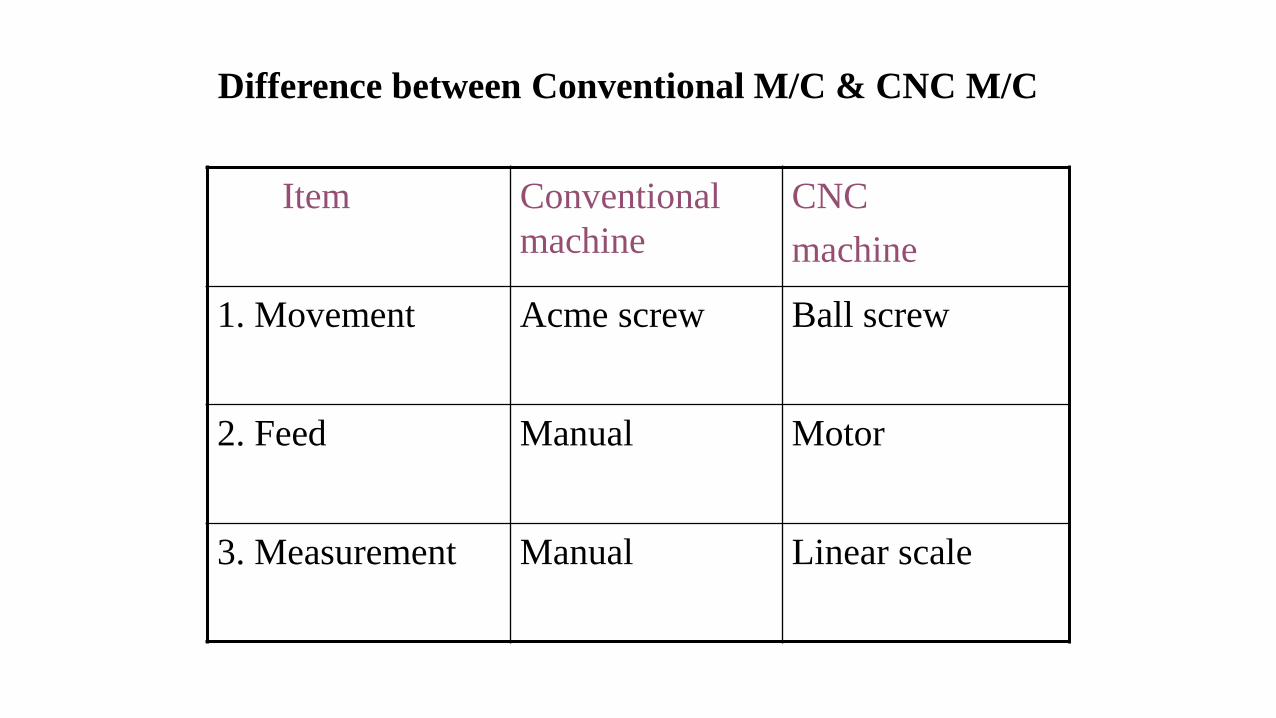
Difference between Conventional M/C & CNC M/C
Item Conventional
machine
CNC
machine
1. Movement Acme screw Ball screw
2. Feed Manual Motor
3. Measurement Manual Linear scale
Advantages of CNC
• Flexible, high accuracy
• Short production time
• Complex shapes
• Short setting time
• No skill requirement
• Short inspection time/ high quality product
• Low cost
Disadvantages of CNC
• High machine cost
• Complicated maintenance
• Skill & training are required for programming and maintenance.
• Parts are imported from aboard.
• High tooling cost
• Temperature, humidity & dust must be controlled.
Why CNC?
HUMAN ➔ LIMITATION
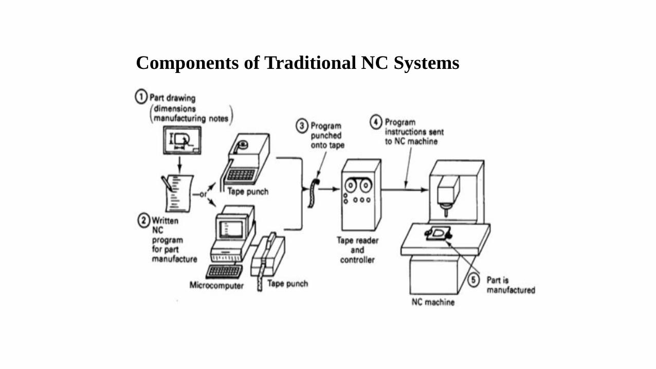
Components of Traditional NC Systems

Direct Numerical Control (DNC)

Direct Numerical Control (DNC)
▪ Feed drive
▪ Measuring system → Direct / Indirect
▪ Work spindle → hydraulic
▪ Cooling system → reduce heat
▪ Tool turret
Component and Function of CNC
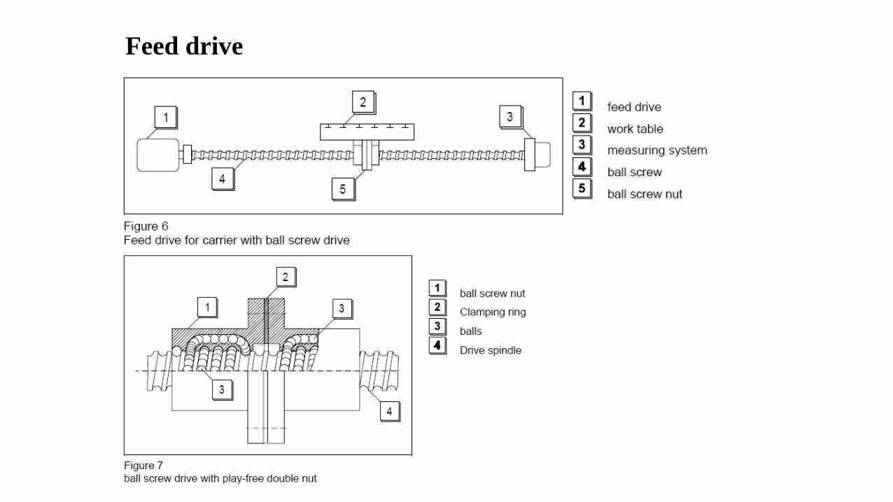
Feed drive
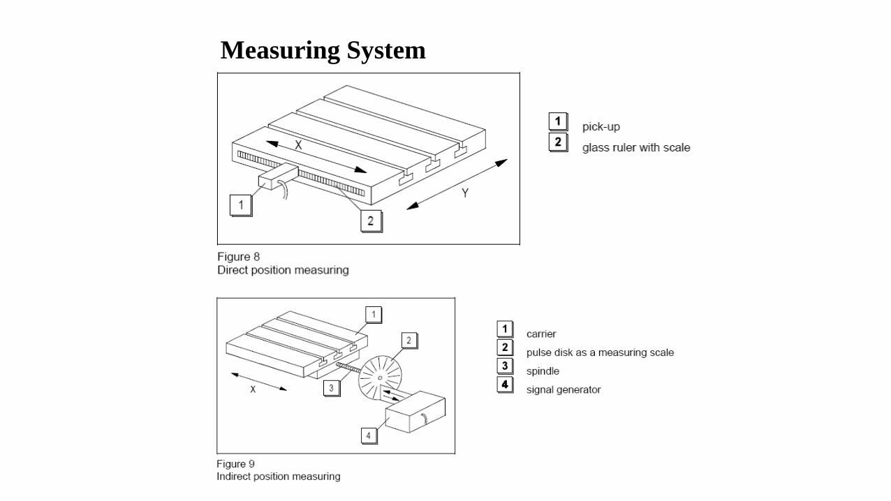
Measuring System
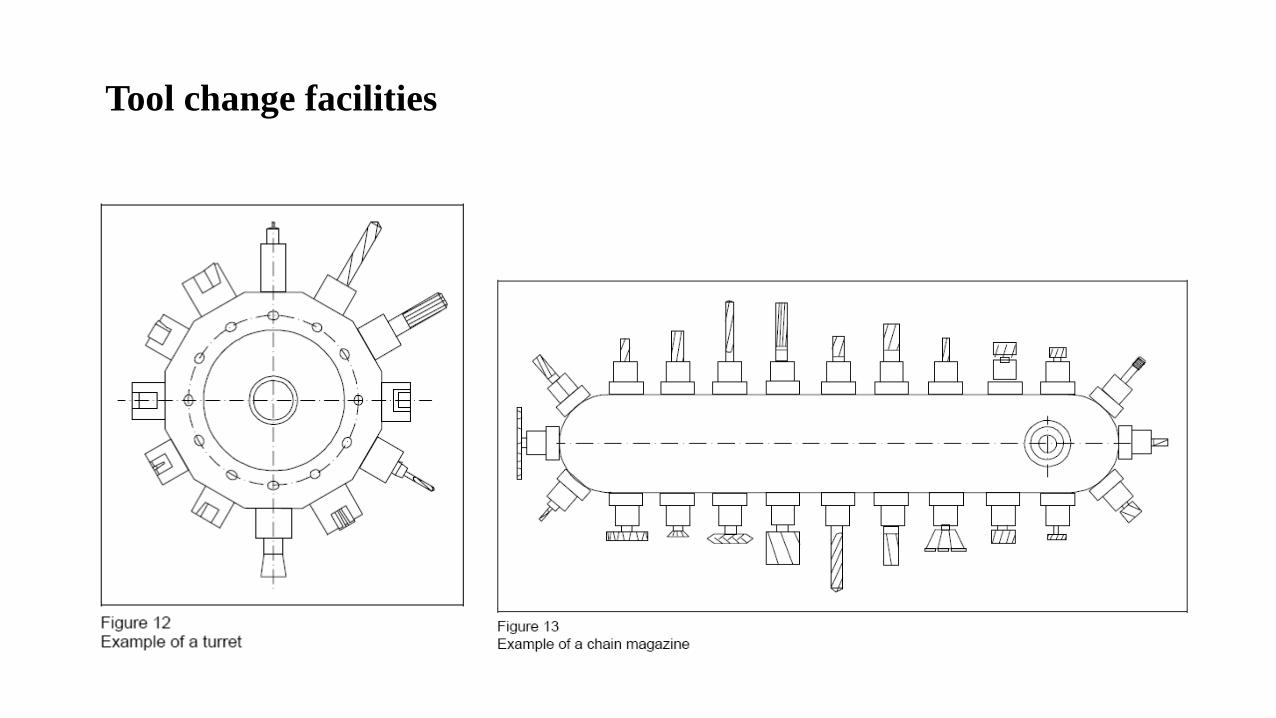
Tool change facilities
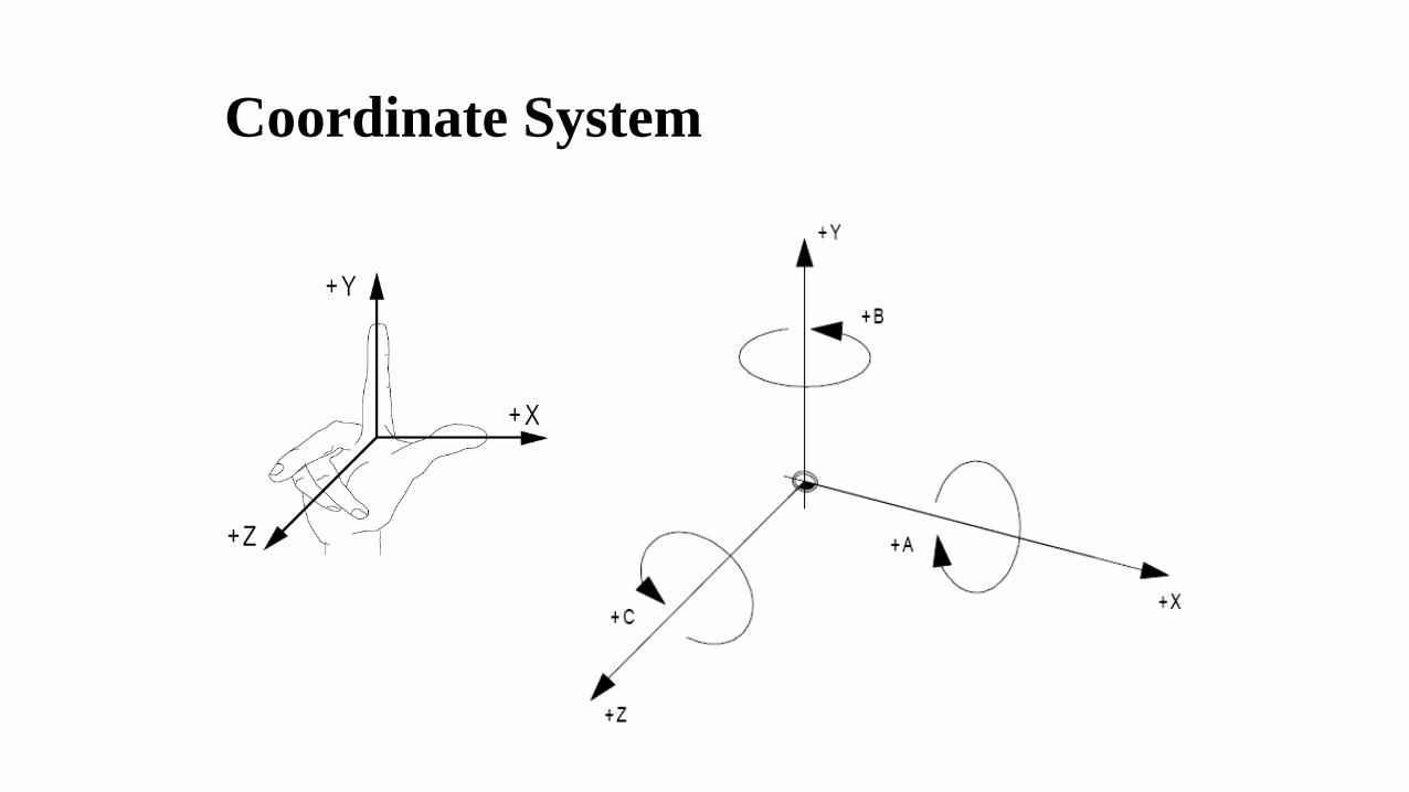
Coordinate System
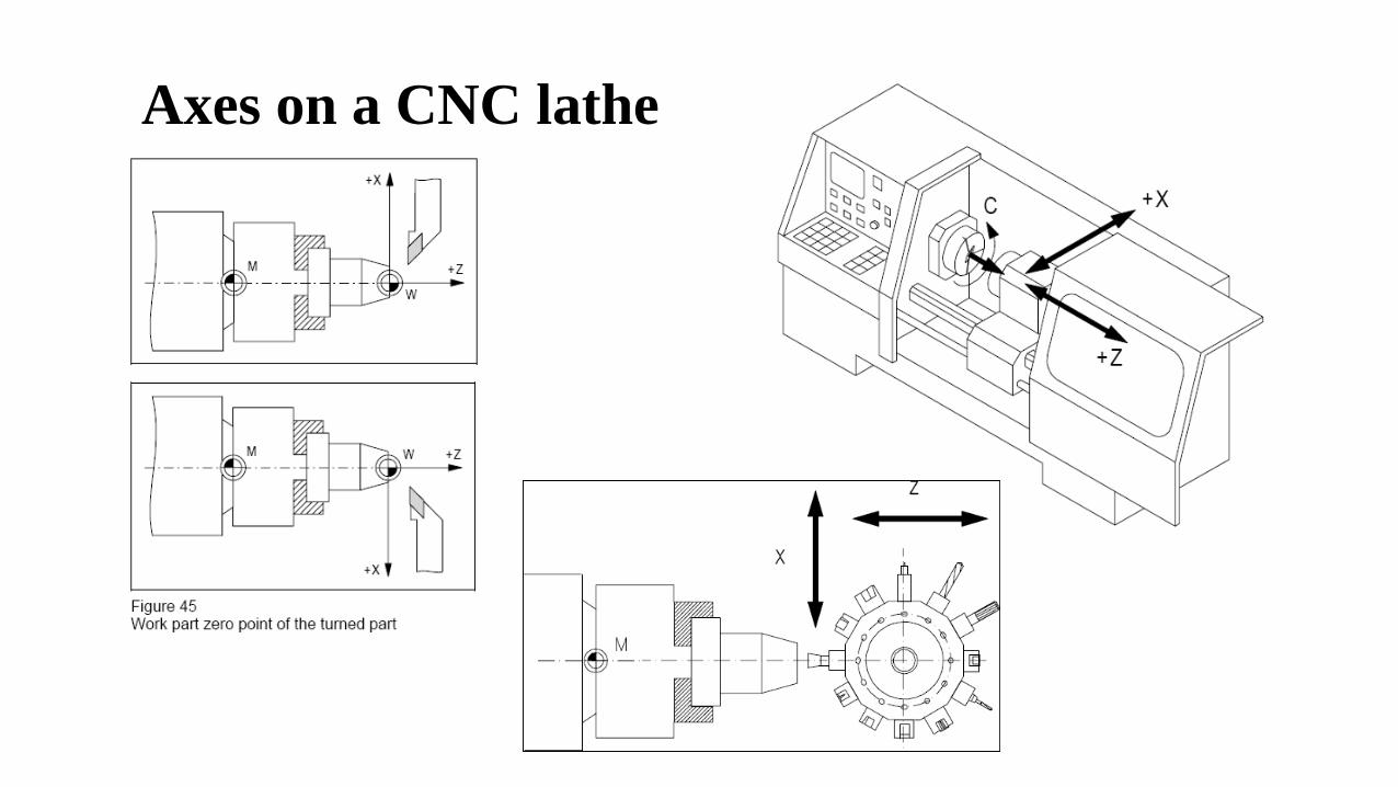
Axes on a CNC lathe

Axes on a CNC milling machine
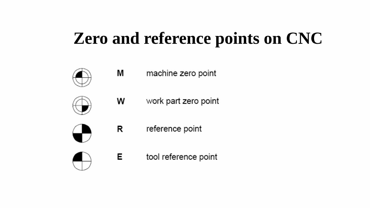
Zero and reference points on CNC
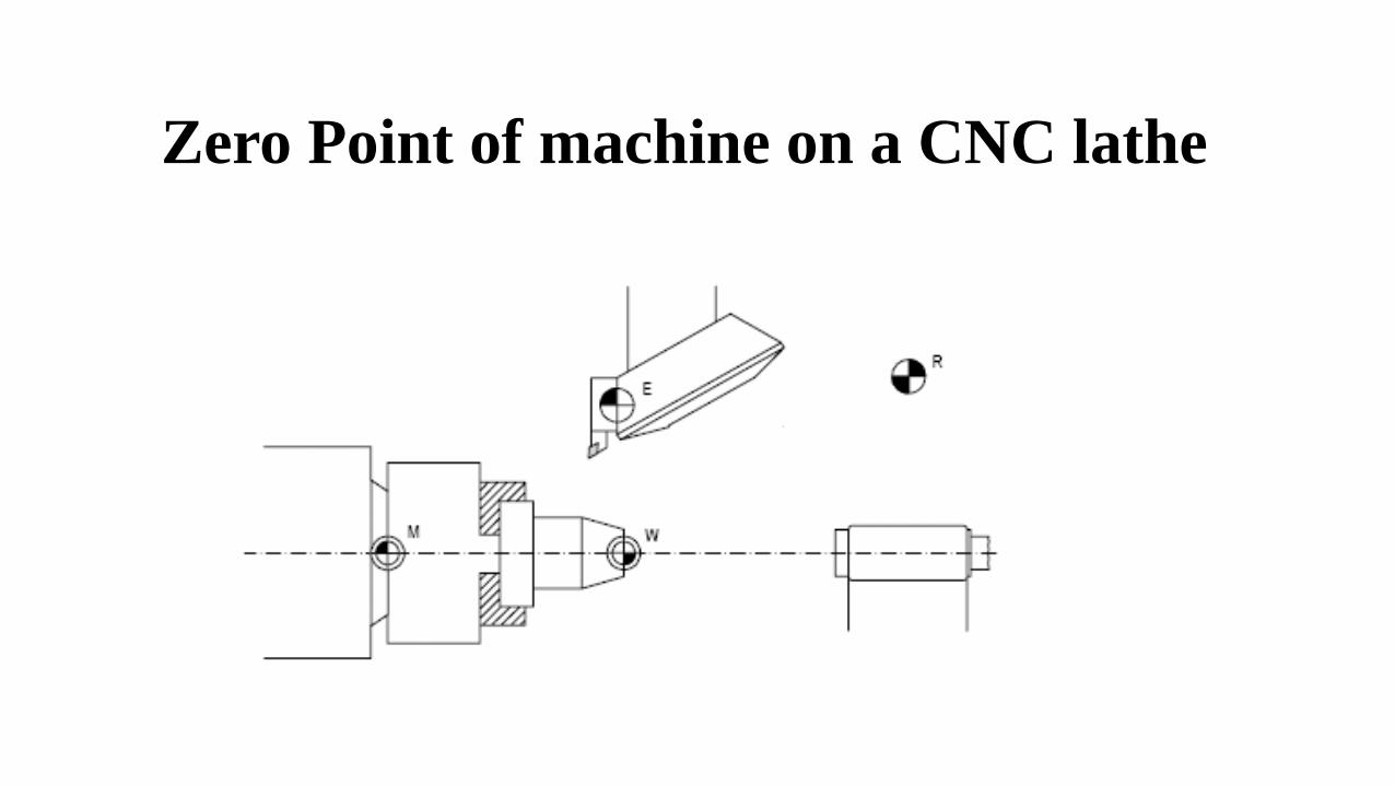
Zero Point of machine on a CNC lathe
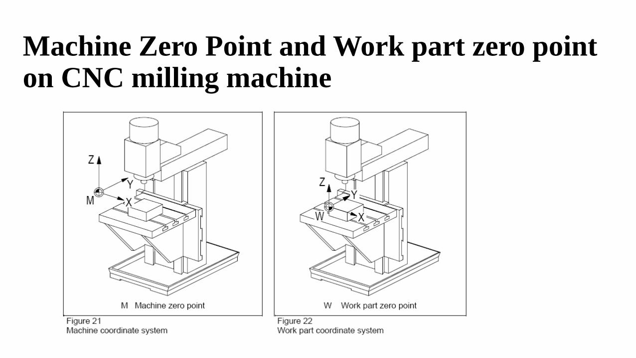
Machine Zero Point and Work part zero point on CNC milling machine
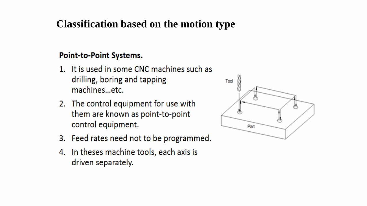
Classification based on the motion type
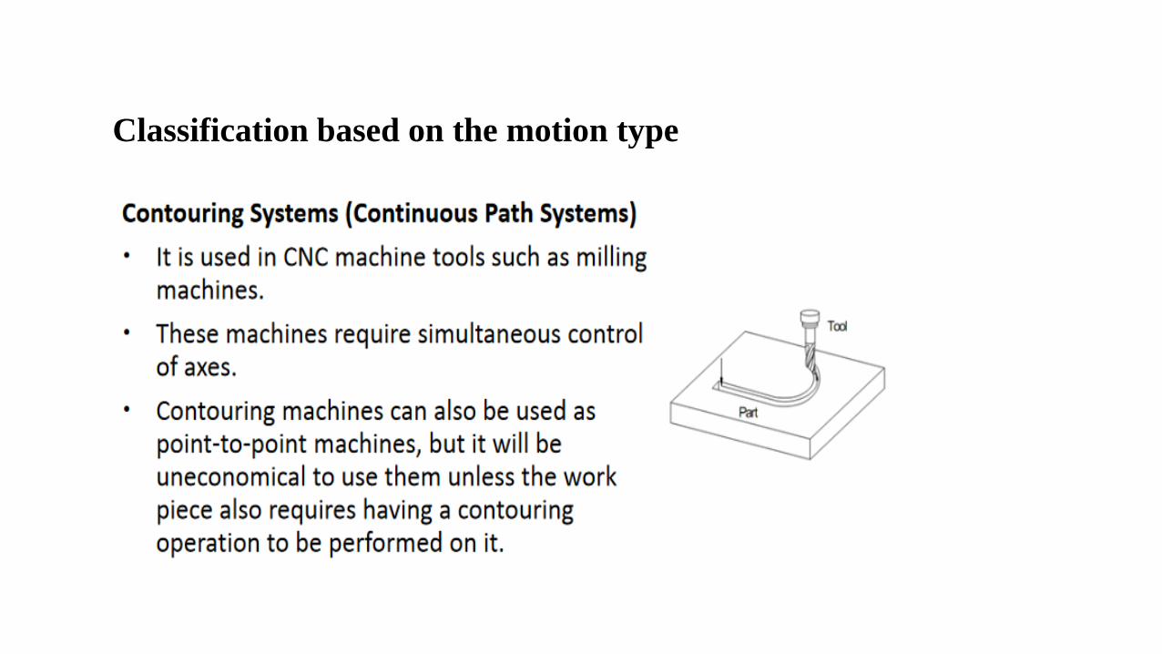
Classification based on the motion type
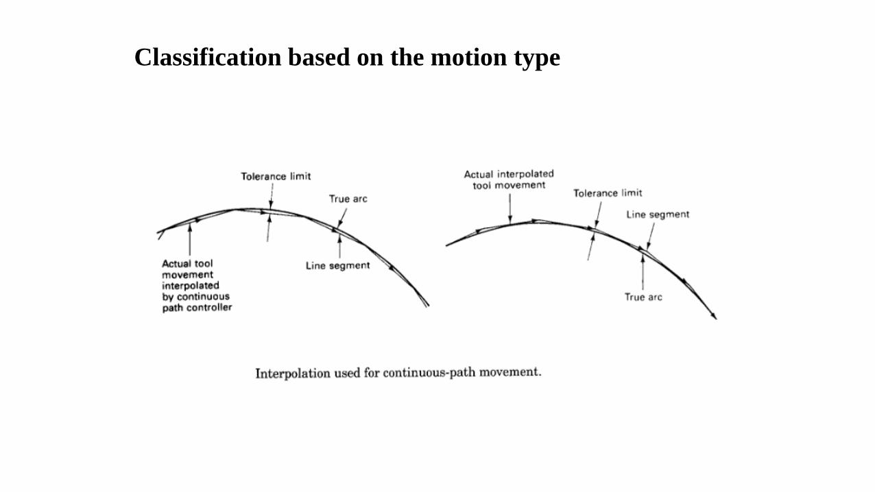
Classification based on the motion type

Classification based on the control loops
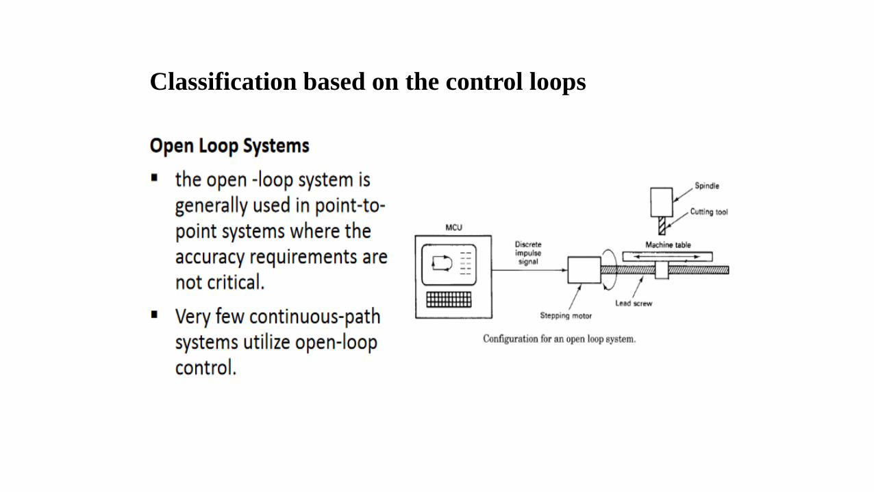
Classification based on the control loops
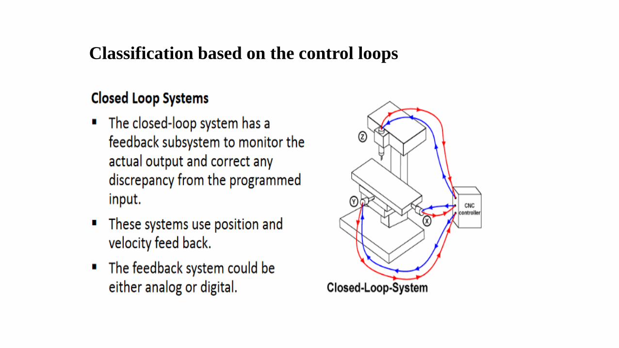
Classification based on the control loops
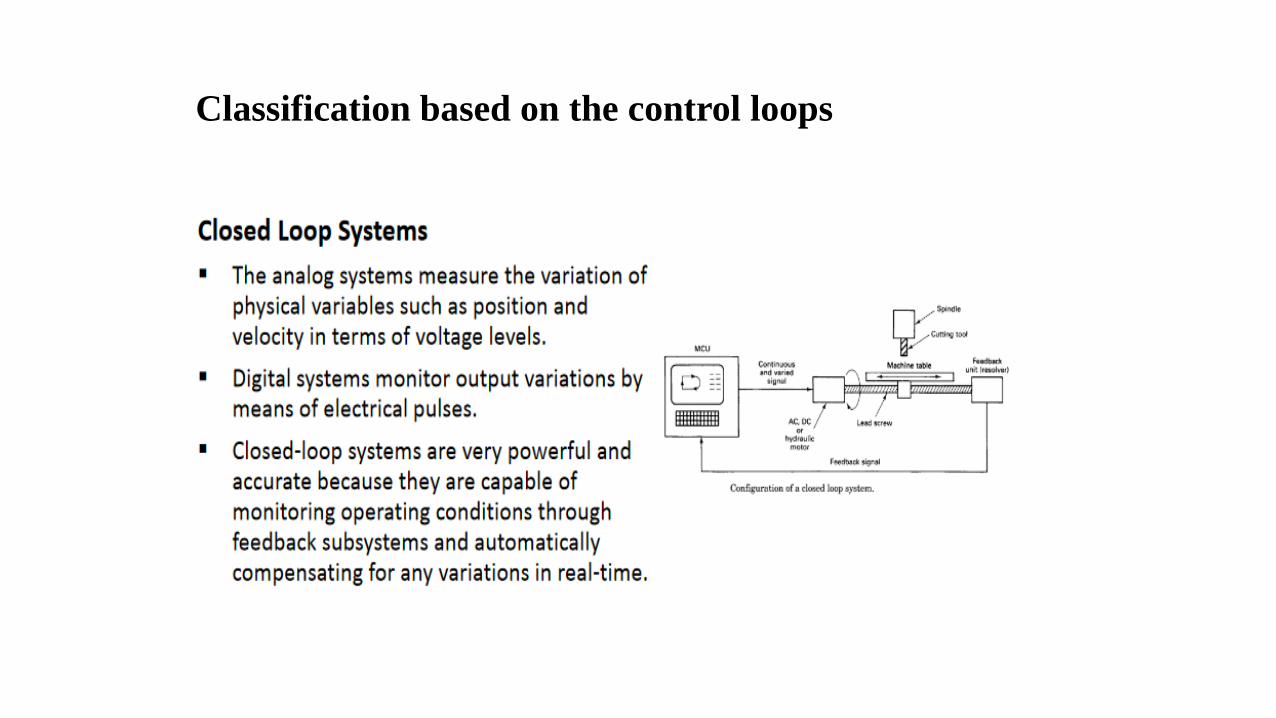
Classification based on the control loops
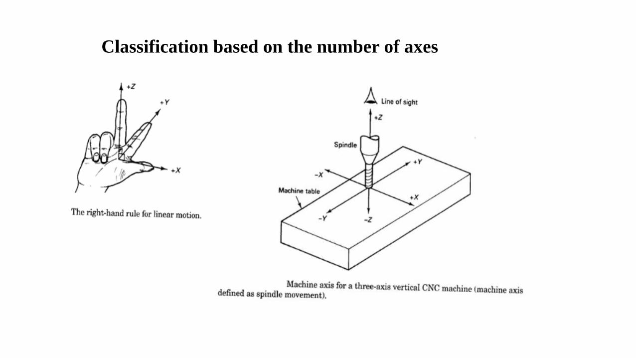
Classification based on the number of axes
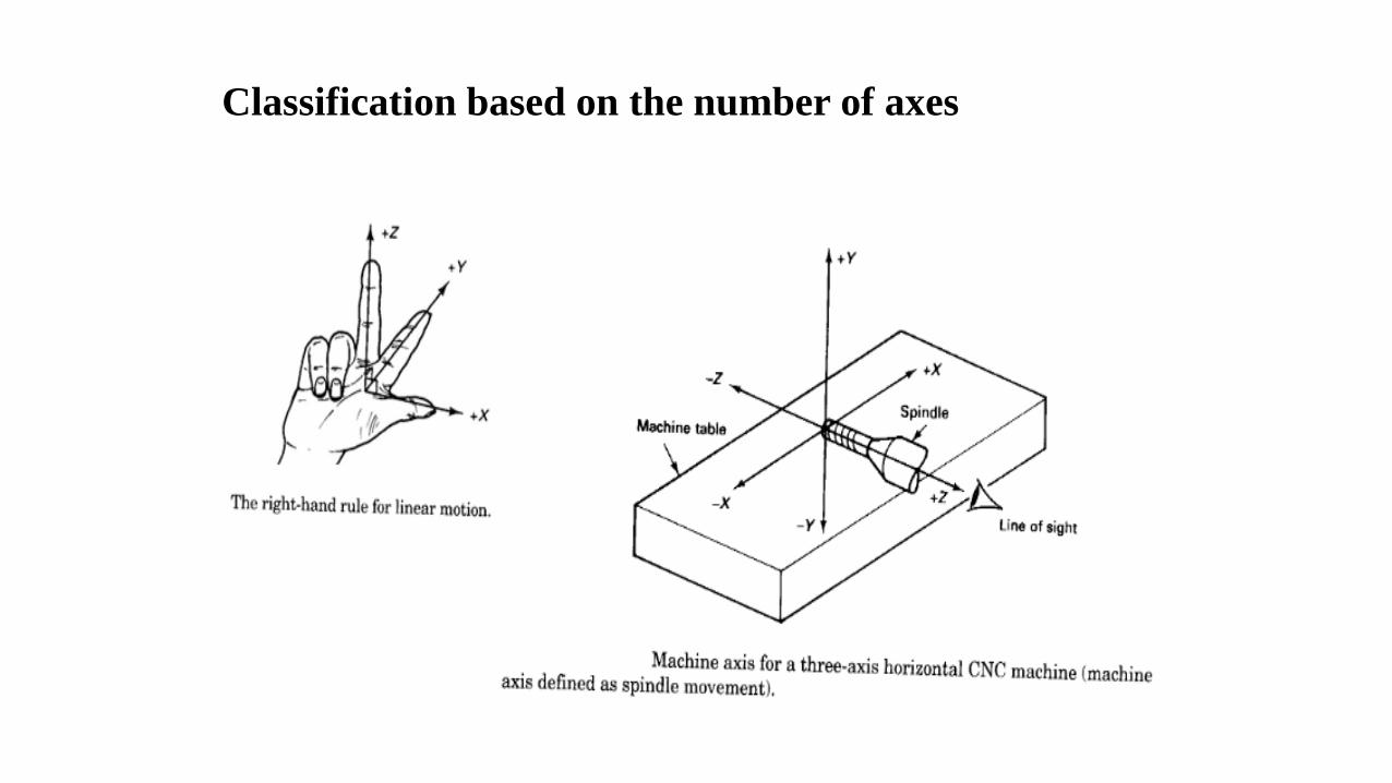
Classification based on the number of axes
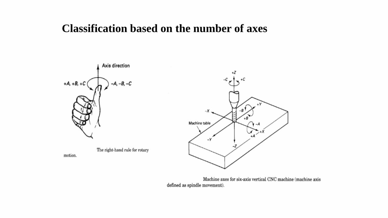
Classification based on the number of axes
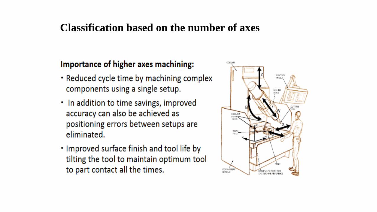
Classification based on the number of axes

Classification based on the power supply
Driving System
➢The requirement is that the driving system has to response accurately according to the programmedinstructions.
➢The motor is coupled either directly or through a gear box to the machine lead screw to moves themachine slide or the spindle.
Three types of electrical motors are commonly used:
1. Stepping motor
2. DC Servo motor
3. AC Servo moto
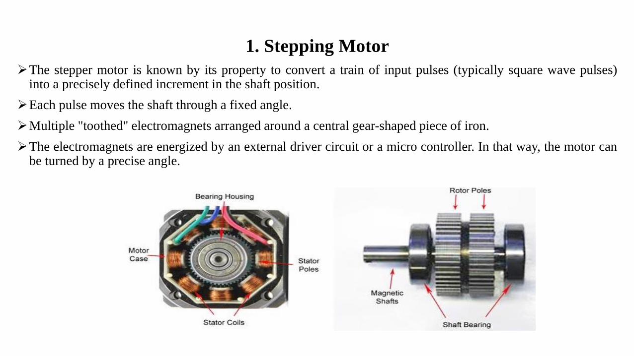
1. Stepping Motor
➢The stepper motor is known by its property to convert a train of input pulses (typically square wave pulses)into a precisely defined increment in the shaft position.
➢Each pulse moves the shaft through a fixed angle.
➢Multiple "toothed" electromagnets arranged around a central gear-shaped piece of iron.
➢The electromagnets are energized by an external driver circuit or a micro controller. In that way, the motor canbe turned by a precise angle.
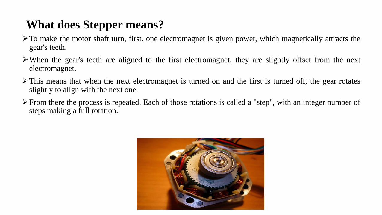
➢To make the motor shaft turn, first, one electromagnet is given power, which magnetically attracts thegear's teeth.
➢When the gear's teeth are aligned to the first electromagnet, they are slightly offset from the nextelectromagnet.
➢This means that when the next electromagnet is turned on and the first is turned off, the gear rotatesslightly to align with the next one.
➢From there the process is repeated. Each of those rotations is called a "step", with an integer number ofsteps making a full rotation.
What does Stepper means?
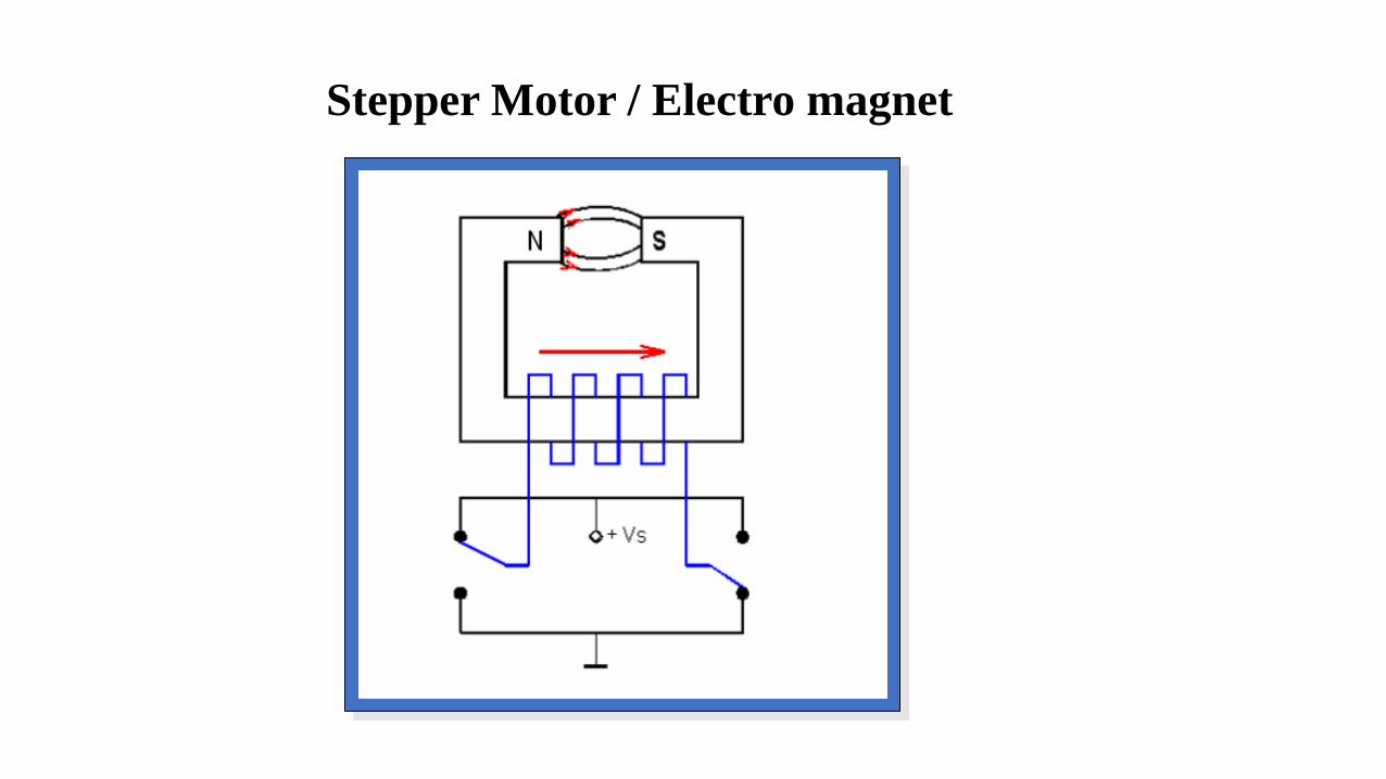
Stepper Motor / Electro magnet
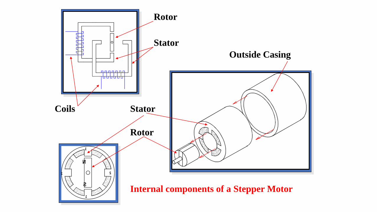
Rotor
Stator
Coils
2
1
S
N
1
2
Outside Casing
Stator
Rotor
Internal components of a Stepper Motor
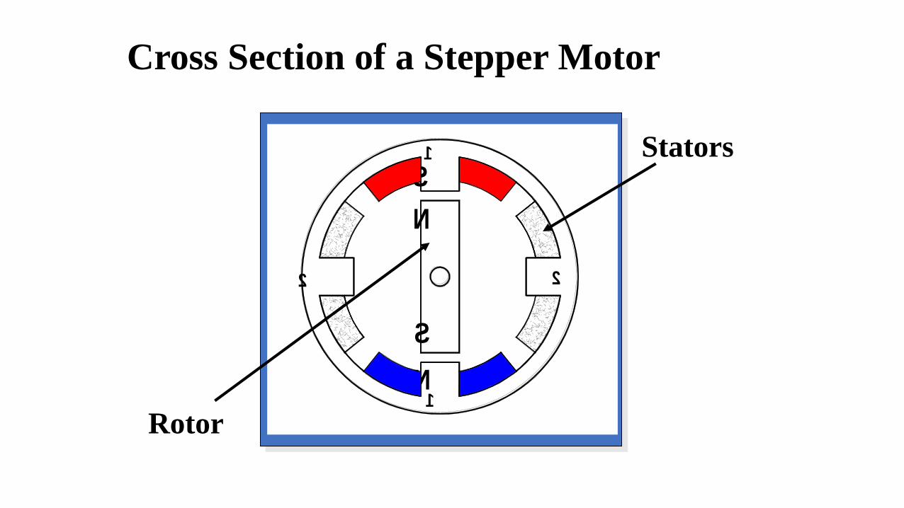
2 2
1
N
S
1
S
N
Stators
Rotor
Cross Section of a Stepper Motor

Four Steps per revolution i.e. 90 deg. steps.
Full Step Operation

Eight steps per. revolution i.e. 45 deg. steps.
Half Step Operation

2 2
1
1
S
N
S
N
NN
S S
1
a b
Winding number 1
2
a b
Winding number 2
One
step6 pole rotor
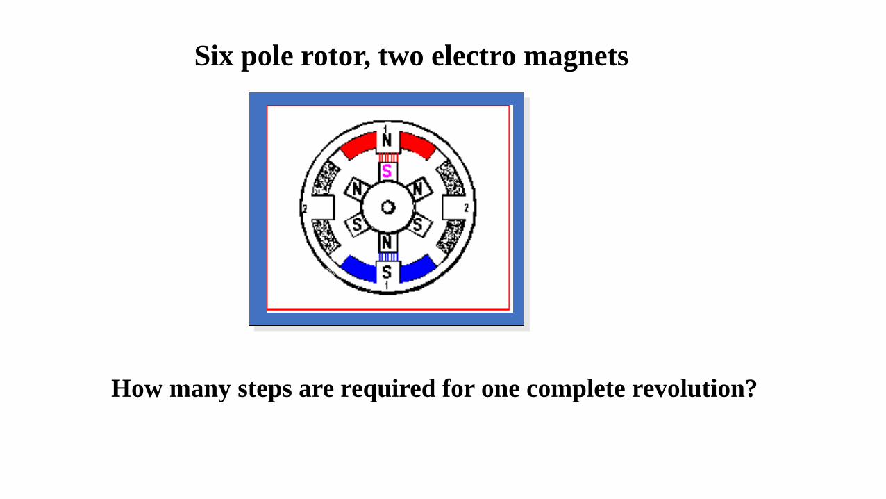
How many steps are required for one complete revolution?
Six pole rotor, two electro magnets

The top electromagnet (1) is turned
on, attracting the nearest teeth of a
gear-shaped iron rotor. With the
teeth aligned to electromagnet 1,
they will be slightly offset from
electromagnet 2
The top electromagnet (1) is
turned off, and the right
electromagnet (2) is energized,
pulling the nearest teeth slightly
to the right. This results in a
rotation of 3.6° in this example.
Practical Stepper motor operation
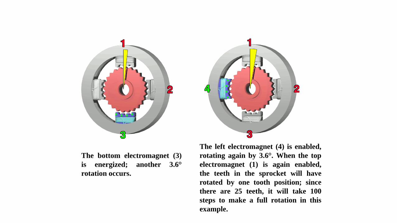
The bottom electromagnet (3)
is energized; another 3.6°
rotation occurs.
The left electromagnet (4) is enabled,
rotating again by 3.6°. When the top
electromagnet (1) is again enabled,
the teeth in the sprocket will have
rotated by one tooth position; since
there are 25 teeth, it will take 100
steps to make a full rotation in this
example.
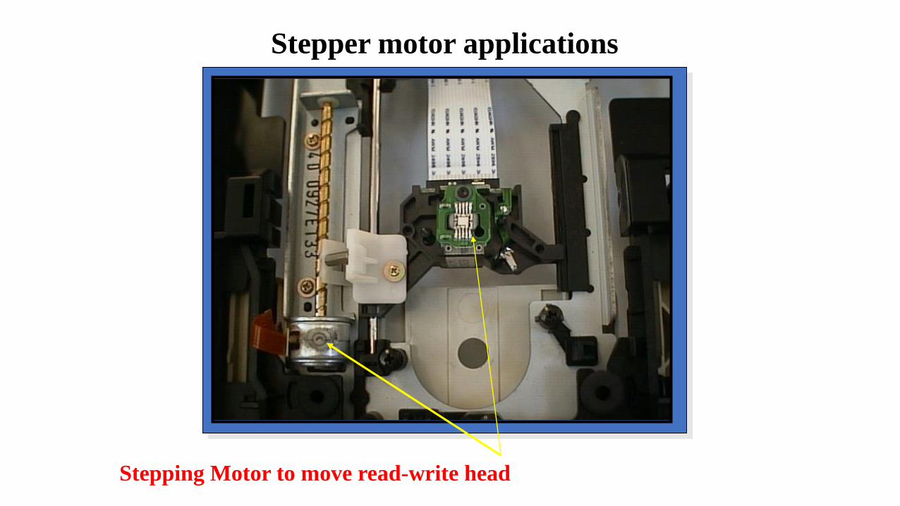
Stepping Motor to move read-write head
Stepper motor applications

Paper feeder on printers
CNC lathes
Stepper motors
Stepper motor applications
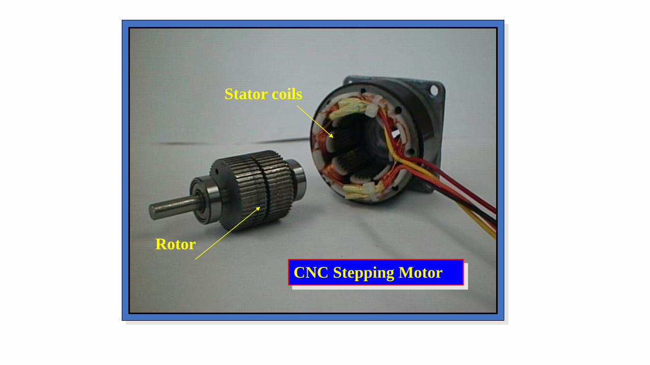
Rotor
Stator coils
CNC Stepping Motor

Step 1 0 0 1 1
Step 2 1 0 1 0
Step 3 1 1 0 0
Step 4 0 1 0 1
+
CW CCW
Control sequence to turn a stepper motor
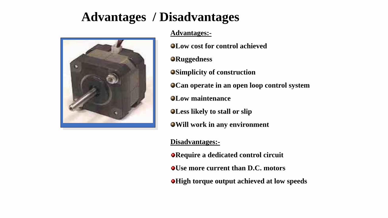
Advantages:-
Low cost for control achieved
Ruggedness
Simplicity of construction
Can operate in an open loop control system
Low maintenance
Less likely to stall or slip
Will work in any environment
Disadvantages:-
Require a dedicated control circuit
Use more current than D.C. motors
High torque output achieved at low speeds
Advantages / Disadvantages
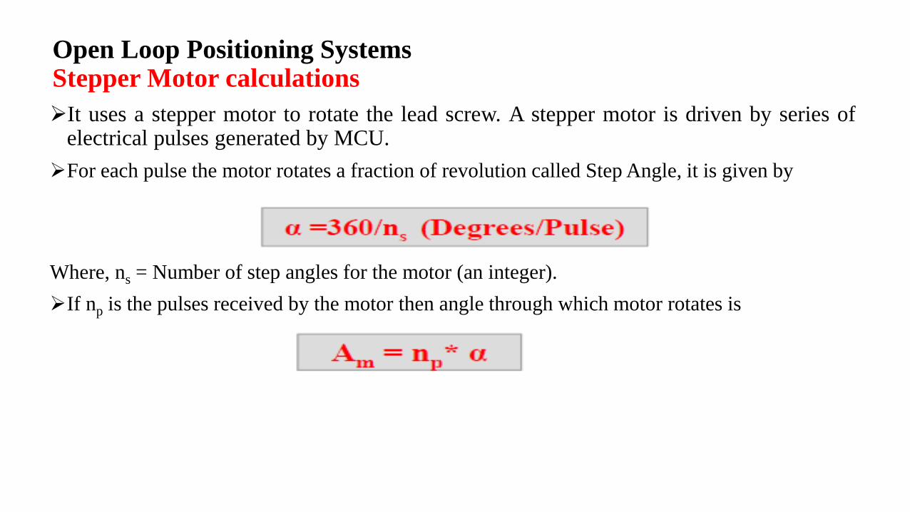
Open Loop Positioning SystemsStepper Motor calculations
➢It uses a stepper motor to rotate the lead screw. A stepper motor is driven by series ofelectrical pulses generated by MCU.
➢For each pulse the motor rotates a fraction of revolution called Step Angle, it is given by
Where, ns = Number of step angles for the motor (an integer).
➢If np is the pulses received by the motor then angle through which motor rotates is
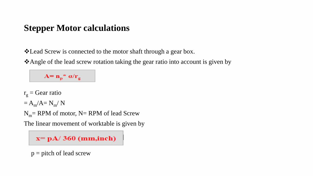
Stepper Motor calculations
❖Lead Screw is connected to the motor shaft through a gear box.
❖Angle of the lead screw rotation taking the gear ratio into account is given by
rg = Gear ratio
= Am/A= Nm/ N
Nm= RPM of motor, N= RPM of lead Screw
The linear movement of worktable is given by
p = pitch of lead screw
Stepper Motor calculations
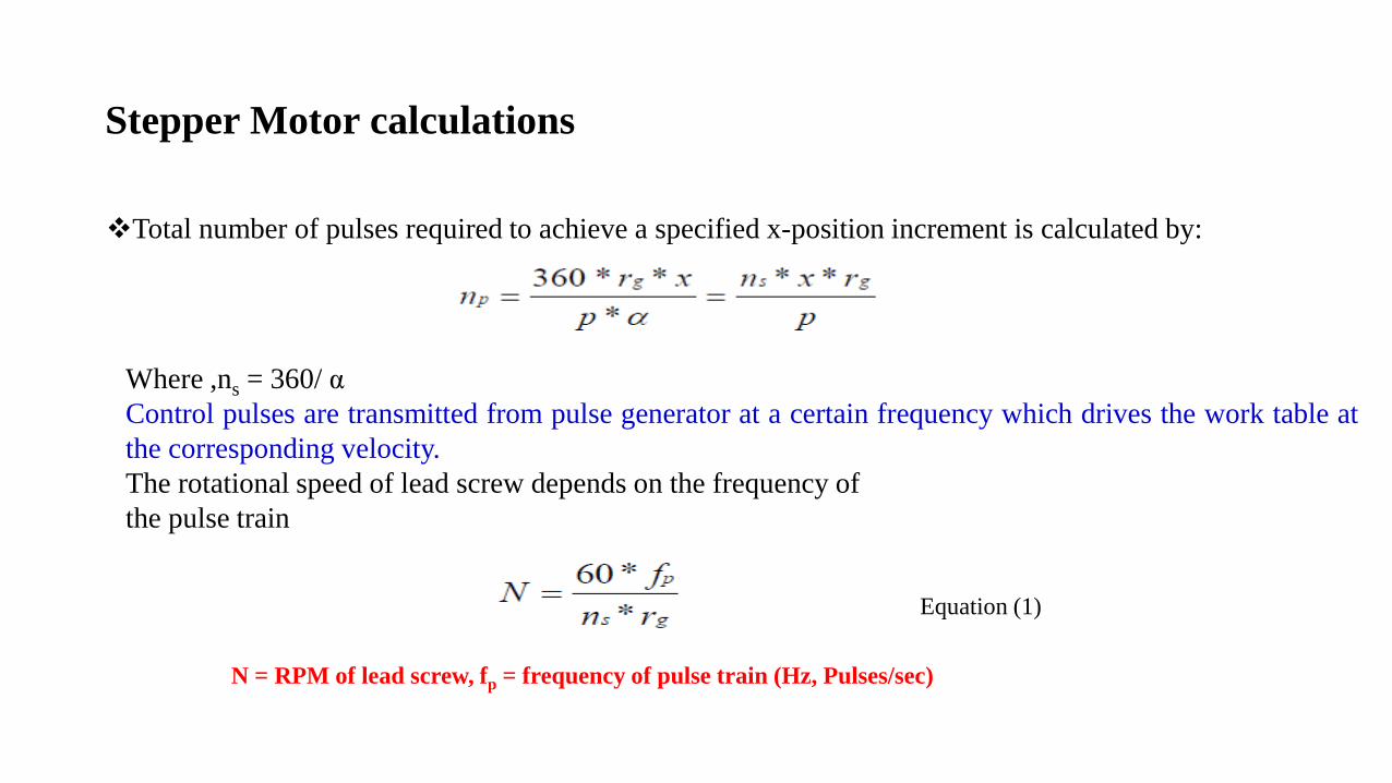
❖Total number of pulses required to achieve a specified x-position increment is calculated by:
Where ,ns = 360/ α
Control pulses are transmitted from pulse generator at a certain frequency which drives the work table at
the corresponding velocity.
The rotational speed of lead screw depends on the frequency of
the pulse train
N = RPM of lead screw, fp = frequency of pulse train (Hz, Pulses/sec)
Equation (1)
Stepper Motor calculations
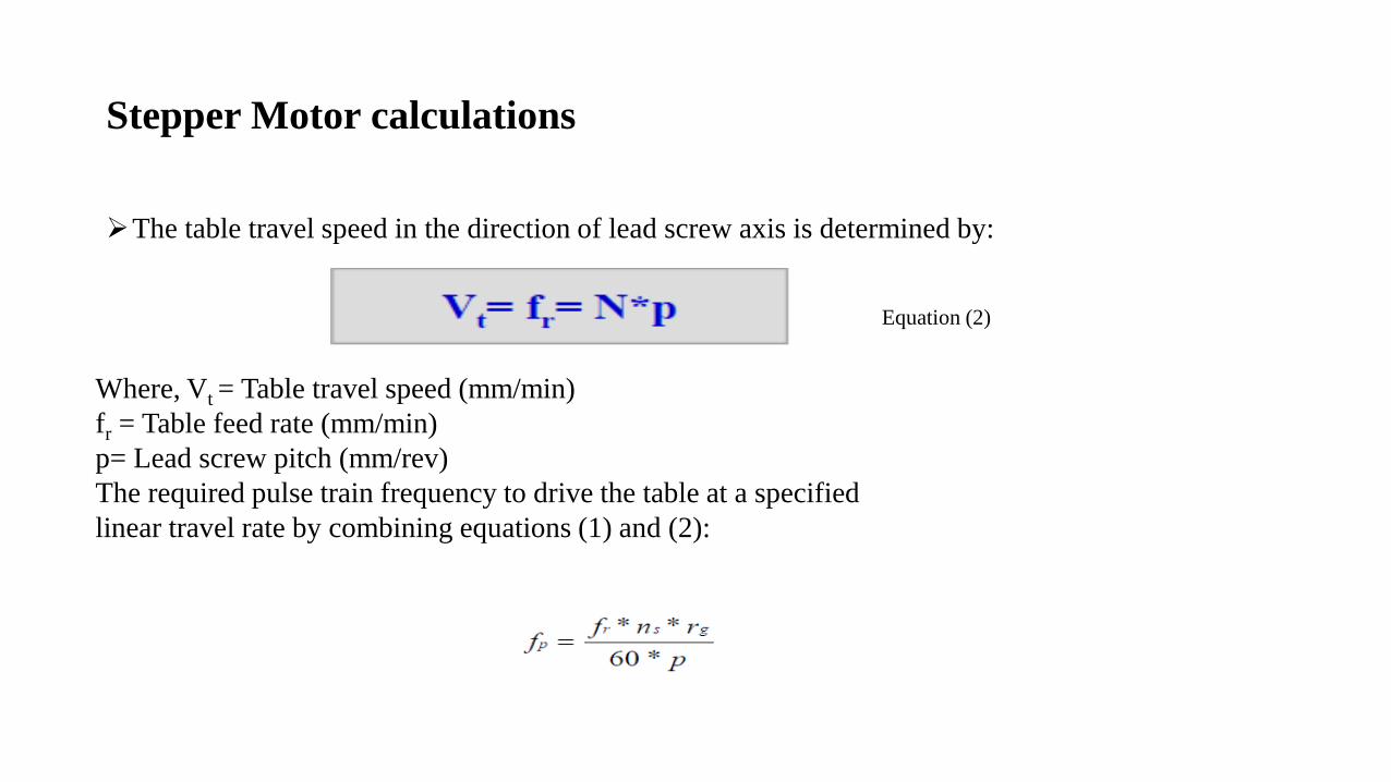
➢The table travel speed in the direction of lead screw axis is determined by:
Where, Vt = Table travel speed (mm/min)
fr = Table feed rate (mm/min)
p= Lead screw pitch (mm/rev)
The required pulse train frequency to drive the table at a specified
linear travel rate by combining equations (1) and (2):
Equation (2)
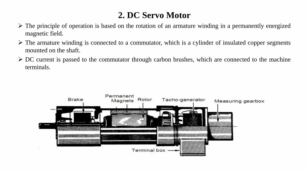
2. DC Servo Motor➢ The principle of operation is based on the rotation of an armature winding in a permanently energized
magnetic field.
➢ The armature winding is connected to a commutator, which is a cylinder of insulated copper segments
mounted on the shaft.
➢ DC current is passed to the commutator through carbon brushes, which are connected to the machine
terminals.

Servo Motor Detail
+ 5V
Actuator
Reduction gear
Position feedback
Potentiometer
(closed loop system)
Small electric DC motor

3. AC Servo Motor➢ In an AC servomotor, the rotor is a permanent magnet while the stator is equipped with 3-phase
windings.
➢ The speed of the rotor is equal to the rotational frequency of the magnetic field of the stator, which
is regulated by the frequency converter.

CNC Programming
➢Programming consists of a series of instructions in form of letter codes
Preparatory Codes:
➢G codes- Initial machining setup and establishing operating conditions
➢N codes- specify program line number to executed by the MCU
➢ Axis Codes: X,Y,Z - Used to specify motion of the slide along X, Y, Z direction
➢ Feed and Speed Codes: F and S- Specify feed and spindle speed
➢ Tool codes: T – specify tool number
Miscellaneous codes – M codes For coolant control and other activities
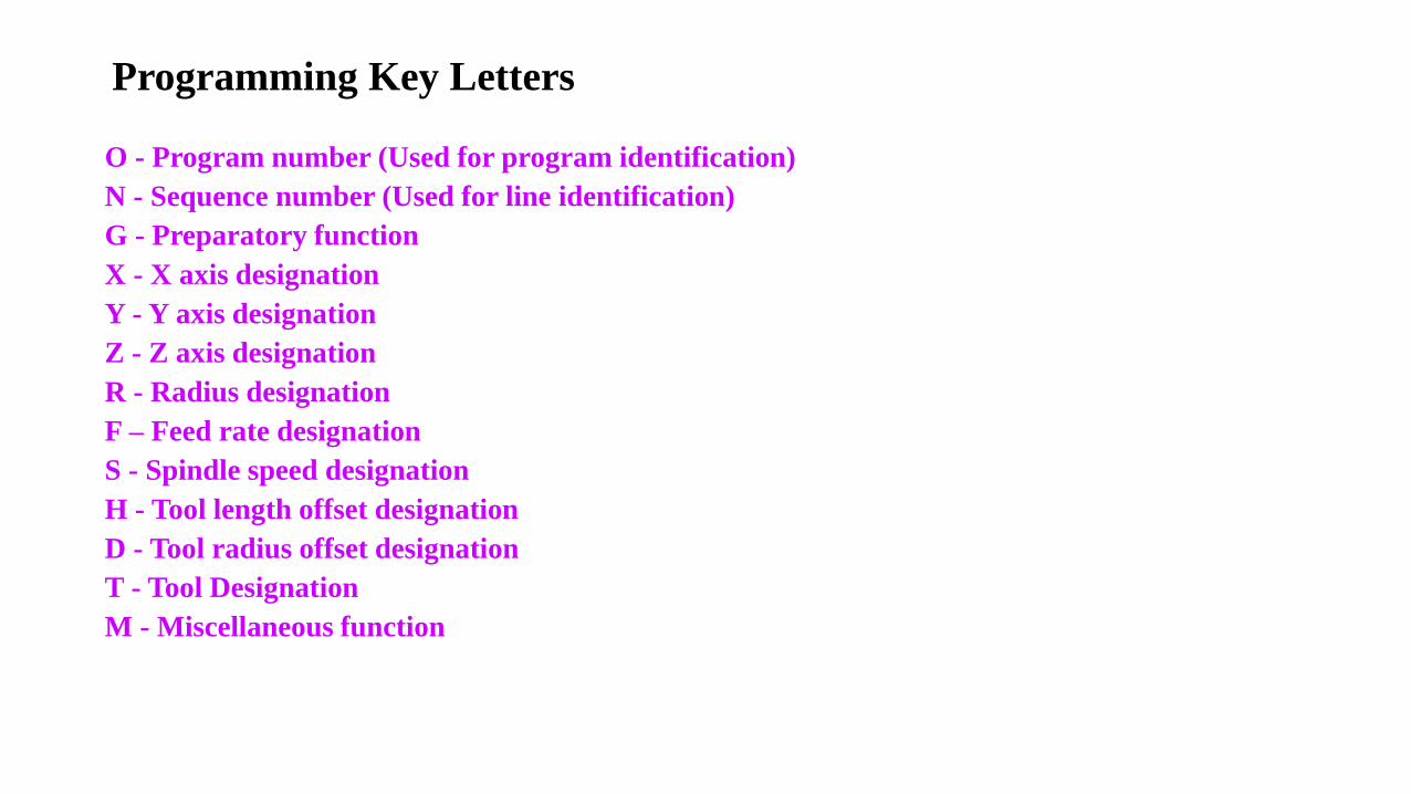
Programming Key Letters
O - Program number (Used for program identification)
N - Sequence number (Used for line identification)
G - Preparatory function
X - X axis designation
Y - Y axis designation
Z - Z axis designation
R - Radius designation
F – Feed rate designation
S - Spindle speed designation
H - Tool length offset designation
D - Tool radius offset designation
T - Tool Designation
M - Miscellaneous function
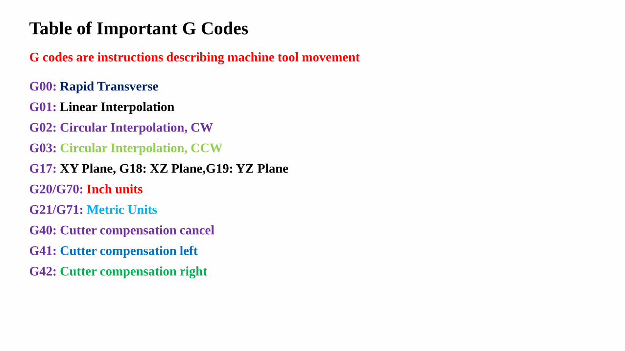
Table of Important G Codes
G00: Rapid Transverse
G01: Linear Interpolation
G02: Circular Interpolation, CW
G03: Circular Interpolation, CCW
G17: XY Plane, G18: XZ Plane,G19: YZ Plane
G20/G70: Inch units
G21/G71: Metric Units
G40: Cutter compensation cancel
G41: Cutter compensation left
G42: Cutter compensation right
G codes are instructions describing machine tool movement
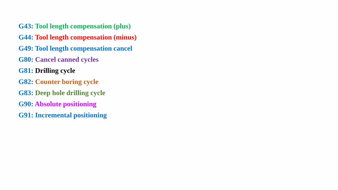
G43: Tool length compensation (plus)
G44: Tool length compensation (minus)
G49: Tool length compensation cancel
G80: Cancel canned cycles
G81: Drilling cycle
G82: Counter boring cycle
G83: Deep hole drilling cycle
G90: Absolute positioning
G91: Incremental positioning
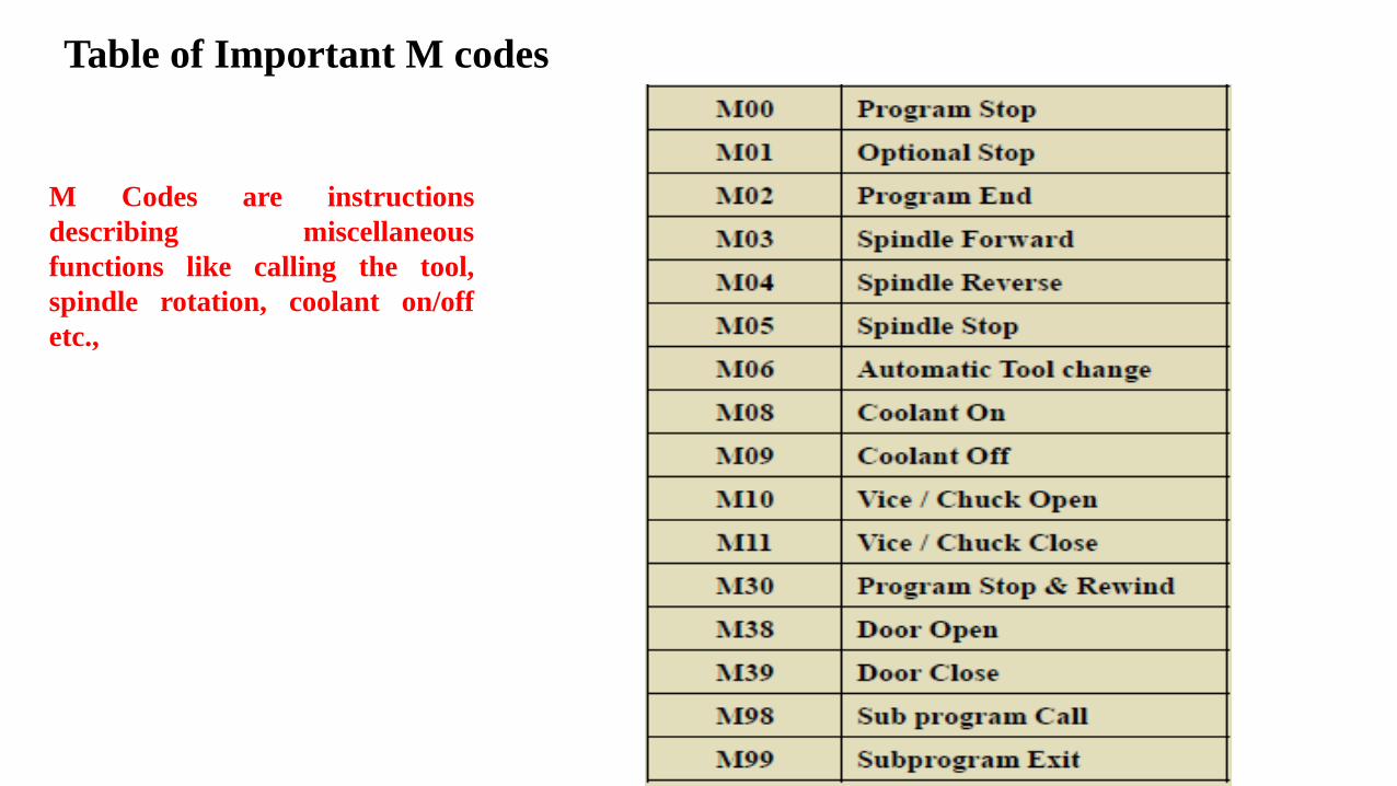
Table of Important M codes
M Codes are instructions
describing miscellaneous
functions like calling the tool,
spindle rotation, coolant on/off
etc.,
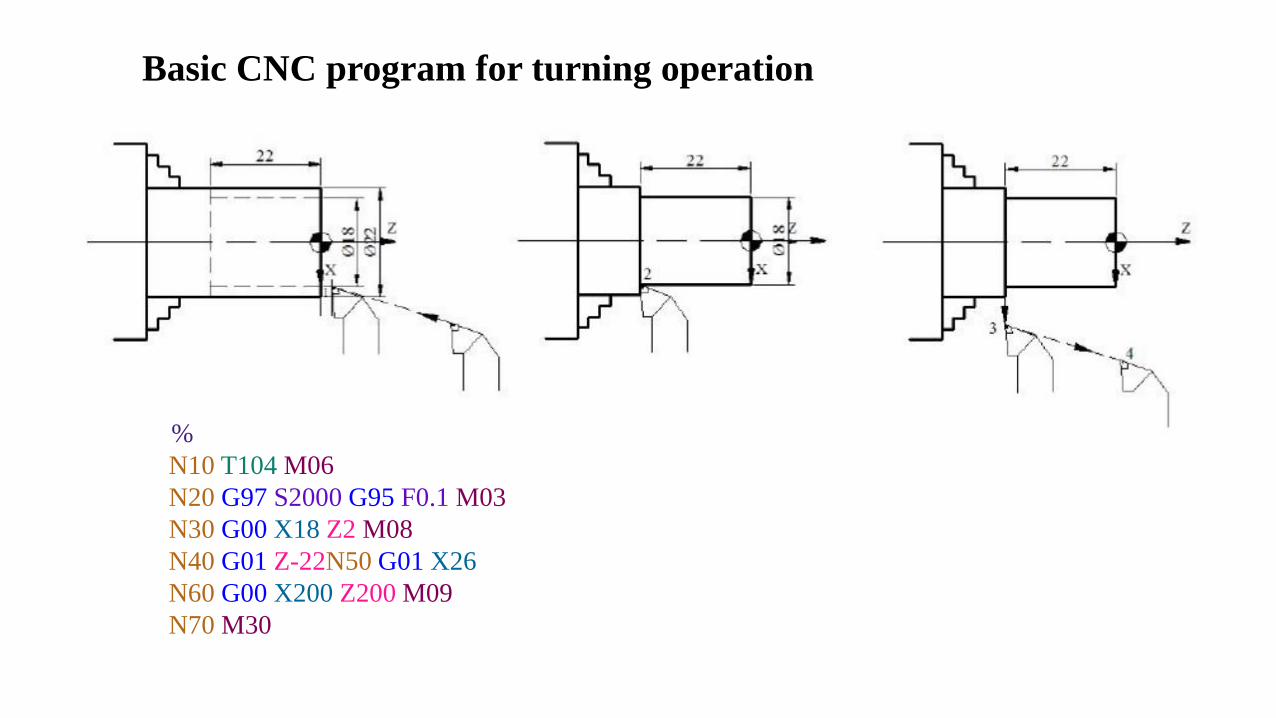
Basic CNC program for turning operation
%
N10 T104 M06
N20 G97 S2000 G95 F0.1 M03
N30 G00 X18 Z2 M08
N40 G01 Z-22N50 G01 X26
N60 G00 X200 Z200 M09
N70 M30
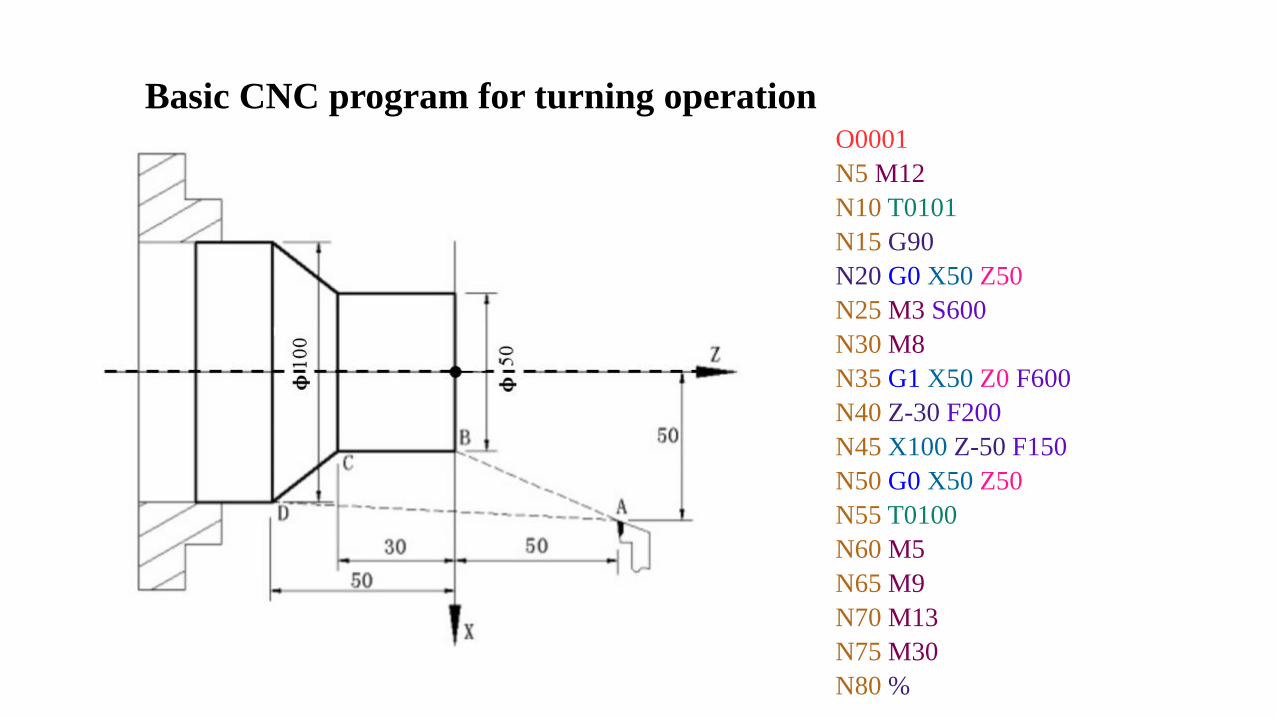
Basic CNC program for turning operationO0001
N5 M12
N10 T0101
N15 G90
N20 G0 X50 Z50
N25 M3 S600
N30 M8
N35 G1 X50 Z0 F600
N40 Z-30 F200
N45 X100 Z-50 F150
N50 G0 X50 Z50
N55 T0100
N60 M5
N65 M9
N70 M13
N75 M30
N80 %
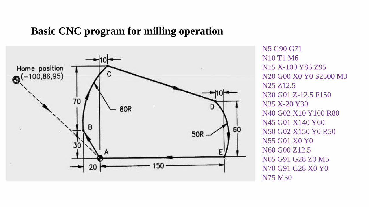
Basic CNC program for milling operation
N5 G90 G71
N10 T1 M6
N15 X-100 Y86 Z95
N20 G00 X0 Y0 S2500 M3
N25 Z12.5
N30 G01 Z-12.5 F150
N35 X-20 Y30
N40 G02 X10 Y100 R80
N45 G01 X140 Y60
N50 G02 X150 Y0 R50
N55 G01 X0 Y0
N60 G00 Z12.5
N65 G91 G28 Z0 M5
N70 G91 G28 X0 Y0
N75 M30

Basic CNC program for milling operation: Circular interpolation
N2 G17 G71 G90 G94 G54
N4 T1 L90
N6 G00 Z5 D5 M3 S500 X20 Y90
N8 G01 Z-2 F50
N10 G02 X60 Y50 I0 J-40
or, N10 G02 X60 Y50 R40
N12 G03 X100 Y50 I20 J0
or, N12 G03 X100 Y50 R20
N14 G00 Z100
N16 M02
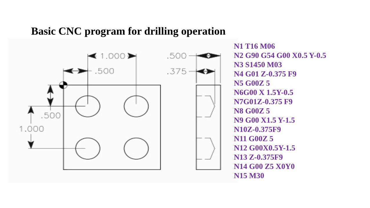
Basic CNC program for drilling operation
N1 T16 M06
N2 G90 G54 G00 X0.5 Y-0.5
N3 S1450 M03
N4 G01 Z-0.375 F9
N5 G00Z 5
N6G00 X 1.5Y-0.5
N7G01Z-0.375 F9
N8 G00Z 5
N9 G00 X1.5 Y-1.5
N10Z-0.375F9
N11 G00Z 5
N12 G00X0.5Y-1.5
N13 Z-0.375F9
N14 G00 Z5 X0Y0
N15 M30
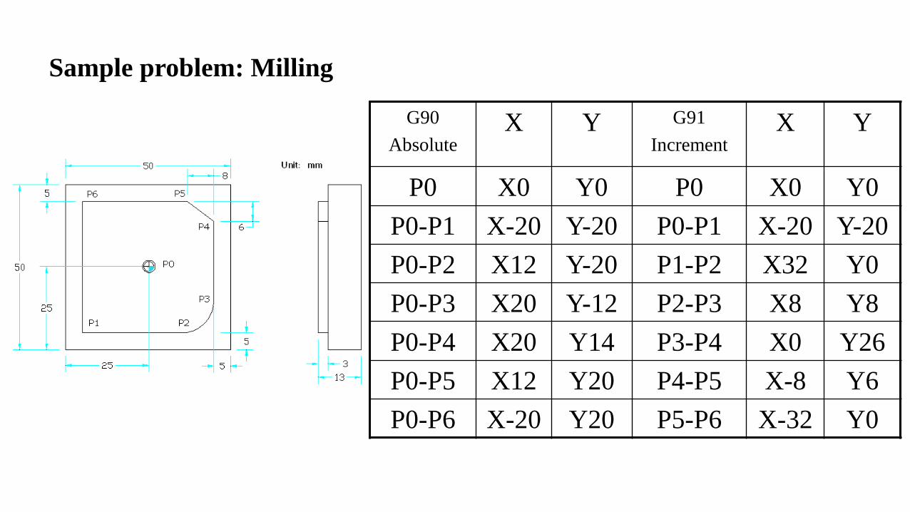
Sample problem: Milling
G90
AbsoluteX Y G91
IncrementX Y
P0 X0 Y0 P0 X0 Y0
P0-P1 X-20 Y-20 P0-P1 X-20 Y-20
P0-P2 X12 Y-20 P1-P2 X32 Y0
P0-P3 X20 Y-12 P2-P3 X8 Y8
P0-P4 X20 Y14 P3-P4 X0 Y26
P0-P5 X12 Y20 P4-P5 X-8 Y6
P0-P6 X-20 Y20 P5-P6 X-32 Y0
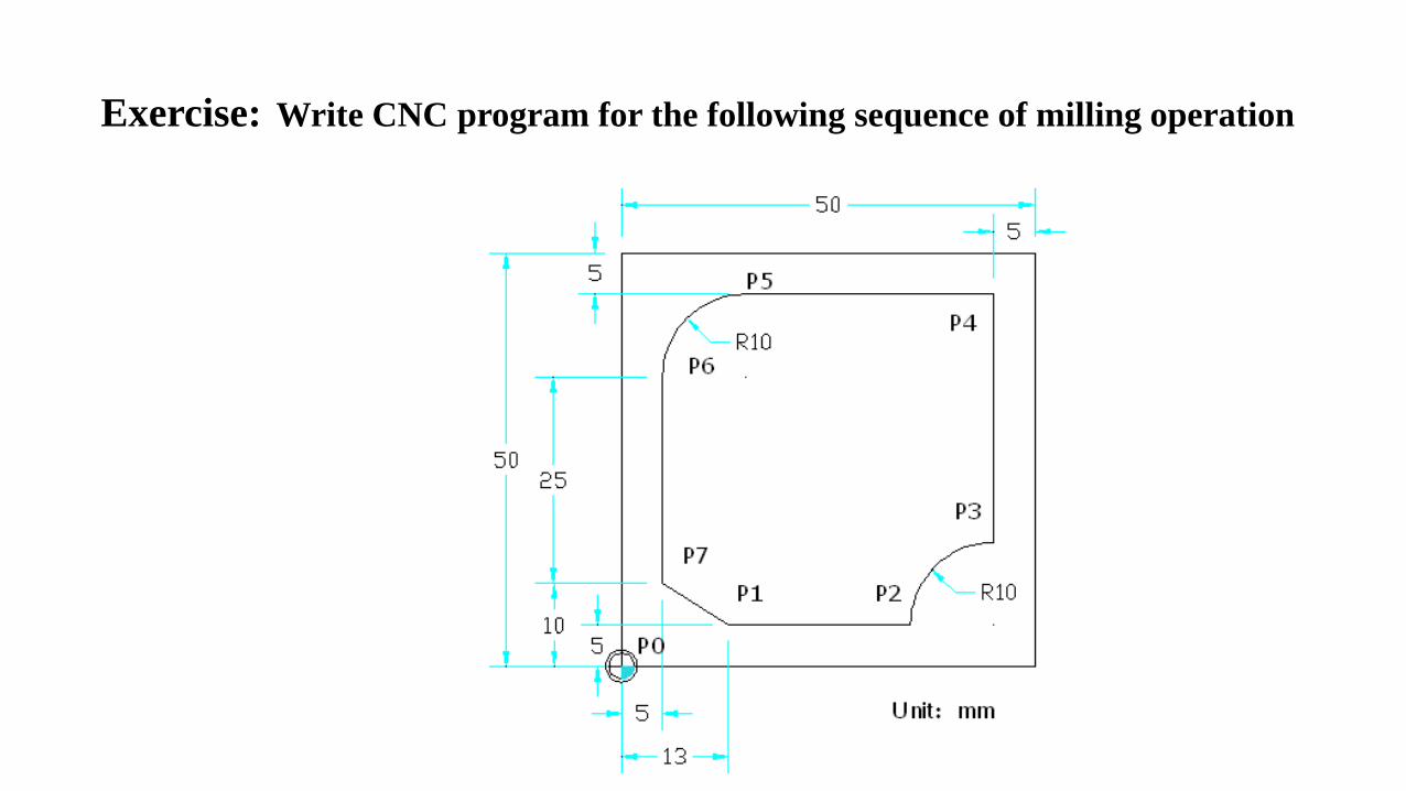
Exercise: Write CNC program for the following sequence of milling operation

Thank You