t617 tdr - go-gddq.com · de piles, deconnecte tous les cables desligar do cabo, as pontas de...
TRANSCRIPT

T617 TDRCable Fault Locator
Operating Manual
Issue 3
Refer to Preface and Safety Instructions before operating
Radiodetection Ltd.Western Drive
BristolBS14 0AF
United Kingdom
Tel: +44 (0) 117 976 7776Fax: +44 (0) 117 976 7775
E-mail: [email protected] 00901286-3A Servomex plc company

© Radiodetection 2007. All rights reserved.
This document is copyright and may not be copied or reproduced or transmitted or modified or used, in whole or in part, in any waywhatsoever, without the specific prior written consent of Radiodetection Ltd.
Radiodetection Ltd. 00901286-3
T617 OPERATING MANUAL 2
For free applications and service advice, please contact Radiodetection on: Tel: +44 (0)1179 767776 Fax: +44 (0)1179 767776

CONTENTS
Page
1. Preface & Safety 42. Introduction 63. Front Panel 104. Power Sources 165. Display 186. Modes 207. Operating Instructions 238. Help 329. Defaults and Power Up Conditions 36
10. Practice use of the T617 3711. Fuse 3812. Cleaning 3813. Specification 3914. Product Safety Data 46
T617 OPERATING MANUAL 3
Radiodetection Ltd. 00901286-3

1. PREFACE & SAFETY
1.1 HEALTH AND SAFETY AT WORK ACT 1974 SECTION 6.1 (C)This product is tested and supplied in accordance with Bicotest’s published specificationsand, when used in normal or prescribed applications and within the parameters specified formechanical and electrical performance, it will not cause danger or hazard to health or safety,provided that normal engineering and safety practices are observed.
All usage of the product must be in accordance with the Operating Manual for this equipmentand any work on the electrical components housed within the machine must be undertakenby qualified personnel .If there is any doubt about any aspect relating to the correct use of thisequipment, contact Bicotest Limited.
1.2 EXPLANATION OF SYMBOLS USED ON THE T617
CAUTION (Refer to operating manual)
Radiodetection Ltd 00901286-3
T617 OPERATING MANUAL 4

1.3 SAFETY PRECAUTIONS
SAFETY:For your own safety, check that there are no hazardous voltagespresent on the cable pair to be tested (greater than 30 V RMS and 42.4 Vpeak or 60 V DC).
For connection to live cables up to 600 V RMS use the Bicotest T600FSor T600FD Blocking Filter.
T617 OPERATING MANUAL 5
Radiodetection Ltd. 00901286-3

2. INTRODUCTION
2.1 T617 OVERVIEWThe T617 is a Time Domain Reflectometer, also known as a Pulse Echo Test set or RadarCable Test Set, that provides visual indication of cable faults. Pulses transmitted into a cableare reflected by cable imperfections. The transmitted pulse and the reflected pulse(s) areshown on the display.The time taken by the pulse to travel to the fault and return is a measureof the distance to the fault. Distance to fault is displayed on the screen after the cursor ispositioned to coincide with the start of the fault pulse. The type of fault can be determined byanalysis of the displayed waveform.
Note: The cable must contain at least two conductors or one conductor and screen.
Radiodetection 00901286-3
T617 OPERATING MANUAL 6

2.2 SAMPLE TRACES
1. Open circuit/high impedance series faults
Note: Positive (upward) reflection.
2. Short circuits/low impedance shunt faults
Note: Negative (downward) reflection
T617 OPERATING MANUAL 7
Radiodetection Ltd. 00901286-3
Transmit Pulse Reflection
Transmit Pulse Reflection

The T617 provides for:
a) examination of a single pair
b) comparison between a good pair and a faulty pair
c) difference between a good pair and a faulty pair, so that reflections from commonfeatures such as joints and change of wire gauge or insulation, cancel out; this permitsobscure faults to be more readily identified
d) location of crosstalk points, i.e. splits and resplits, by transmitting on one pair andreceiving on the other
e) ‘before and after’ comparison using the memory facility.
2.3 POWER SOURCEThe T617 is powered by 8 ‘C’size batteries which are fitted in a compartment at the rear of theinstrument.The unit is supplied with LR14 alkaline batteries.Rechargeable batteries may beused, but the instrument has no built in charging facility.
The T617 will automatically switch off when the batteries are almost discharged.
Radiodetection Ltd. 00901286-3
T617 OPERATING MANUAL 8

2.4 MAIN FEATURESFigure 1 shows the front panel of T617.
T617 OPERATING MANUAL 9
Radiodetection Ltd. 00901286-3
Figure 1

3. FRONT PANEL
3.1 CONTROLS
Switches T617 ON. The T617 has an automatic switch off feature 5 mins afterthe last key operation to conserve battery life.
Switches T617 OFF.
Rotary control to adjust the contrast of the screen display.
Rotary control used to:
Balance out the transmitted pulse at the start of the trace for near end meas-urements in the absence of a reference cable.
Assisting in identifying fault reflections at long distance.
Not operational in some modes.
Radiodetection Ltd. 00901286-3
T617 OPERATING MANUAL 10

Some of the following keys are not operational in some modes (see section 7).
BACKLIGHTSwitches the display backlight ON.The backlight may be turned off by pressingthe key a second time or by waiting for the automatic backlight switch off to occur(5 mins after switch on).
CURSORAdjusts the position of the vertical line cursor. Moves the cursor to the left orright. If held down, the cursor will move slowly at first and then more quickly untilit reaches the edge of the screen.
TRACE EXPANSION (ZOOM)Causes the trace around the cursor to be displayed with greater resolution.Theamount of expansion is dependent on range. Pressing the key a second timecauses the display to return to the full range display. Not operational on the 25m range. Maximum expansion is x4 on ranges of 300 m and above.
T617 OPERATING MANUAL 11
Radiodetection Ltd. 00901286-3

DIELECTRICUsed to set the appropriate velocity factor for the pair under test. Causes the di-electric value to be incremented or decremented. If held down, the displayedvalue will change slowly at first, then more quickly until the limit is reached.Alsoused to enter the numbers ‘3’ and ‘5’ when required.
RANGESelects the displayed range.Causes the display range to increase or decrease.If the key is held down, the T617 will step through the available ranges. Alsoused to enter the numbers ‘1’ and ‘2’ when required.
Radiodetection Ltd. 00901286-3
T617 OPERATING MANUAL 12
5
+3
+2
1

SHIFTAdjusts the vertical position of the trace. Causes the trace to be shifted up ordown. If the key is held down, the trace will shift slowly at first and then morequickly until the internal shift control reaches its limit. When L1 & L2 are dis-played, both waveforms will move. When L1 & M are displayed, only L1 wave-form will move. Also used to enter the numbers ‘4’ or ‘6’ when required.
AMPLITUDEAdjusts the vertical amplitude of the display. Causes the next higher or lowergain range to be selected. If the key is held down, the T617 will step through theavailable gain ranges.
T617 OPERATING MANUAL 13
Radiodetection Ltd. 00901286-3
4
6
+

PULSE WIDTHToggles the pulse width between wide and narrow. Not operational on the 25mrange.
MEMORYIf the display is showing a live trace, pressing this key enables the display andthe T617 settings to be saved.Also acts as number ‘8’ when required.
Enables the memory to be recalled.Also acts as number ‘7’ when required.
Radiodetection Ltd. 00901286-3
T617 OPERATING MANUAL 14
SAVE
8
RECALL
7
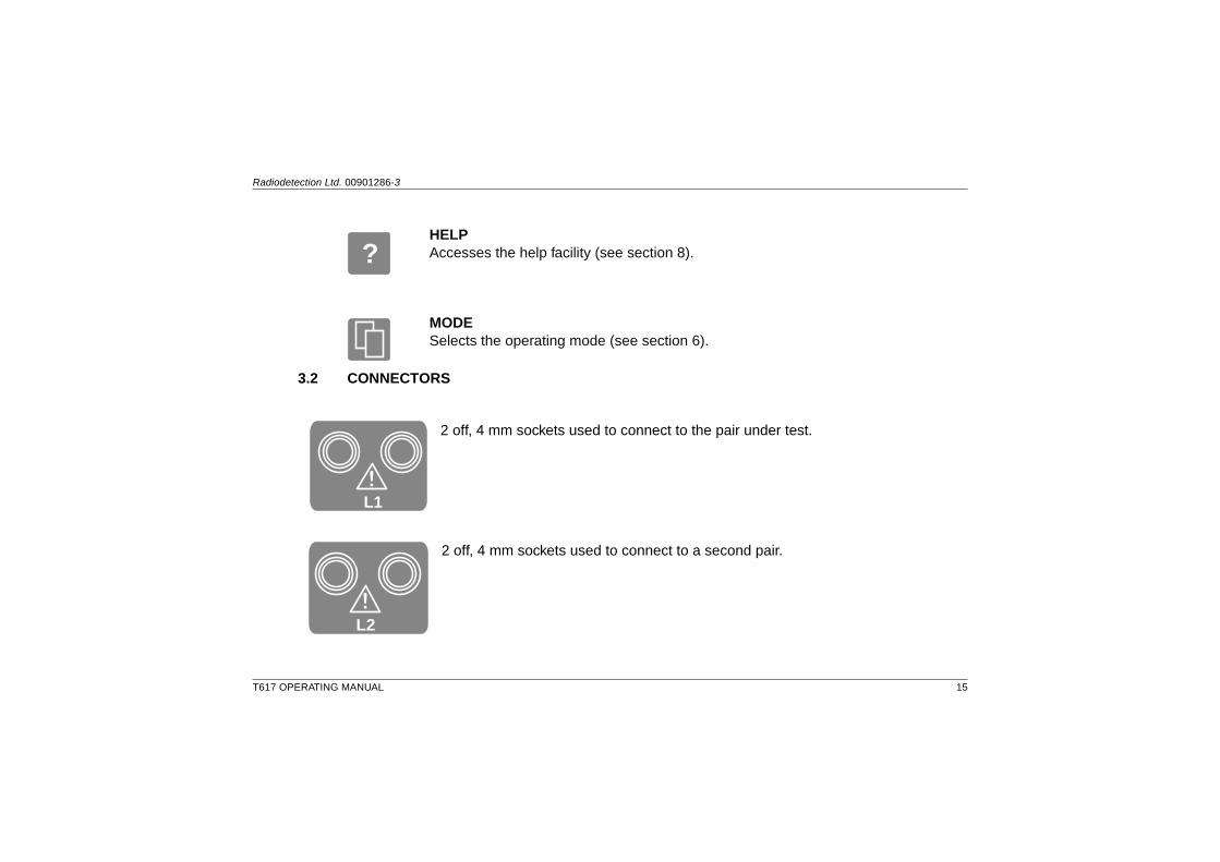
HELPAccesses the help facility (see section 8).
MODESelects the operating mode (see section 6).
3.2 CONNECTORS
2 off, 4 mm sockets used to connect to the pair under test.
2 off, 4 mm sockets used to connect to a second pair.
T617 OPERATING MANUAL 15
Radiodetection Ltd. 00901286-3
!
L1
L2!L2!
L2!
?

4. POWER SOURCES
4.1 BATTERIES
SAFETY:Disconnect test leads from any cables before opening the batterycompartment.
Figure 2 shows the rear view of T617.
8 ‘C’ size batteries are fitted (either LR14 alkaline or NiCad).The battery compartment is revealed by releasing the two fasteners and removing the cover.The indicated polarity must be observed when fitting new batteries.LR14 alkaline batteries cannot be charged and may explode if charging is attempted.ChargeNiCad batteries as recommended by the battery manufacturer.
Battery Replacement:
When fitting batteries ensure that batteries touch the battery holder contacts andeach other.
Radiodetection Ltd. 00901286-3
T617 OPERATING MANUAL 16

4.2 MEMORY BACK UP BATTERYThe memory back up battery is a lithium manganese cellwhich is part of the main PCB assembly.The life expectancy istypically four years and replacement is recommended everytwo years during a routine service to avoid possible loss ofstored traces.
T617 OPERATING MANUAL 17
Radiodetection Ltd.00901286-3
DISCONNECT TEST LEADSFROM CABLES BEFOREOPENING BATTERYCOMPARTMENT
AVANT D’OUVRIR LE COMPARTIMENTDE PILES, DECONNECTE TOUS LESCABLES
DESLIGAR DO CABO, AS PONTAS DEPROVA, ANTES DE ABRIR OCOMPARTIMENTO DA BATERIA
DESCONECTE LAS CARGAS DE PRUEBADE CUALQUIER CABLE ANTES DEQUITAR LA CUBIERTA DE LAS BATERIAS
Figure 2

5. DISPLAYFigure 3 shows the T617 display.
Radiodetection Ltd. 00901286-3
T617 OPERATING MANUAL 18
Figure 3

CURSOR: Shows the cursor position in terms of metres, feet or time (as selected throughthe HELP system). When the marker is on, the distance between the cursorand the marker is displayed.
RANGE/ZOOM: When the display is not in ZOOM, the selected range in metres, feet or time(as selected through the HELP system) is displayed. In Zoom mode, this isreplaced by the word ‘ZOOM’ with the display being expanded about the cursorposition.
LOW BAT: When the battery capacity is low, a flashing battery symbol will be displayed.
FILTER: When the filter is switched in is displayed.
GAIN: Shows the selected gain from A1 (minimum gain) to A9 and then Aa through toAf (maximum gain).
PULSEINDICATOR:
Shows if the transmit pulse is wide or narrow.
DIEL MODE: The units for the dielectric mode (‘P’ - PVF, ‘V’ - velocity, ‘V/2’ - velocity/2).
DIEL VALUE: Shows the velocity in terms of PVF, velocity or velocity/2 (as selected throughthe HELP system.
MODE: Shows the operational mode of the T617 (see section 6).
T617 OPERATING MANUAL 19
Radiodetection Ltd. 00901286-3

6. MODESThe T617 has eight operating modes. The mode is selected by pressing the MODE key andthen pressing the appropriate key as shown on the menu.
6.1 LIVE MODES (L1, L2, L1 & L2, L1 – L2, XTALK)
6.1.1 LINE 1 (L1)The pulse is transmitted on the L1 sockets and the resulting waveform displayed. This is thenormal mode of operation for fault finding on a single cable.
6.1.2 LINE 2 (L2)This mode is identical to the L1 mode except that the L2 sockets are used.
6.1.3 DUAL (L1 & L2)This mode combines the L1 and L2 modes, showing two traces on the screen - one from L1and the other from L2. It is normally used for comparison of two cables.
Radiodetection Ltd. 00901286-3
T617 OPERATING MANUAL 20

6.1.4 DIFF (L1 – L2)Displays the difference between the two waveforms (L1 and L2). It is normally used to identifythe differences between a known good cable and a faulty one. It is also a convenient way tofind close in faults, as two similar cables may balance each other more accurately than onecable and the internal balance control.
6.1.5 XTALK (CROSSTALK)Outputs the transmit pulse on L1, but displays the signal received on L2. Normally used forthe location of crosstalk, splits and resplits. A typical trace is shown in figure 4.
T617 OPERATING MANUAL 21
Radiodetection Ltd. 00901286-3
Figure 3
split resplit

6.2 MEMORY MODES (M, L1 & M, L1 – M)The memory facility is provided to facilitate ‘before’ and ‘after’ comparison of the samepair/conductor. If the fault is not readily obvious the waveform is stored in a memory, the T617is disconnected from the cable, and some external stimulus is applied to the cable .Once theexternal stimulus has been disconnected the L1 terminals are connected to the faultypair/conductor, and the waveform compared to the memorised waveform using the L1 & Mmode or the L1 – M mode.
6.2.1 M (MEMORY)This mode allows the memorised waveform to be displayed.
6.2.2 DUAL (L1 & M) (LINE 1 AND MEMORY)The signal received from L1 and the memory are displayed.
6.2.3 DUAL (L1 – M) (LINE 1 - MEMORY)The difference between the signal received from L1 and the memory are displayed.
Radiodetection Ltd. 00901286-3
T617 OPERATING MANUAL 22

7. OPERATING INSTRUCTIONS
SAFETY:For your own safety, check that there are no hazardous voltagespresent on the cable pair to be tested (greater than 30 V RMS and 42.4 Vpeak or 60 V DC.
7.1 GENERALFor correct operation of the T617 the cable to be tested must be de-energised. If the cable isenergised or is likely to become energised, then the Blocking Filter must be used.
Note: The fault distance displayed includes the 2m connecting lead. This should besubtracted from the reading obtained.
Provide the T617 with power by fitting batteries.
Switch the T617 ON by pressing the ON button and select the required mode. Adjust thecontrast control to give a clear display.The operating mode may be changed at anytime by pressing the MODE key and selectingthe required mode.
T617 OPERATING MANUAL 23
Radiodetection Ltd. 00901286-3

7.2 LIVE MODES (L1, L2, L1 & L2, L1 – L2, XTALK)Connect the cable under test to the L1 and/or L2 sockets as appropriate using the test leads.
Adjust the dielectric value either using the DIEL+ and DIEL– keys or via the HELP system(see section 8) to the required value. If dielectric value is not known refer to section 2 of theTDR Application Guide.
Select the range to cover the full cable length.
Adjust the BALANCE control to minimise the transmitted pulse at the start of trace if in L1, L2or L1 & L2 mode.
Adjust the gain using the AMPLITUDE keys until the reflection can be clearly seen.Move the cursor with the CURSOR keys until it is over thepoint at which the start of the reflected pulse just leavesthe horizontal (see figure 4).
If any range except the shortest is used, the ZOOM keymay be used to show the trace in more detail. Thedistance to the fault may be read off from the screen.Remember to deduct the length of the test lead unless themarker is used.
Radiodetection Ltd. 00901286-3
T617 OPERATING MANUAL 24
Figure 4

The marker may be used to:
a) Eliminate the length of the test lead.
b) To measure between any two features on the trace.
The marker appears as a dotted line, and the cursor can move either side of it, so the distancethat appears on the screen in the cursor position can be positive or negative depending onwhether the cursor is to the right or the left of the marker. The distance is the true distancefrom marker to cursor irrespective.
Once placed, the marker will stay in the same position even if the range is changed.
7.2.1 To eliminate the length of the test leadConnect only the test lead to the instrument, and select the 25 m range.Adjust the controls sothat the reflection from the end of the test lead is obtained. Position the cursor at the start ofthis reflection (see figure 4).
Press HELP and select option 3 “SET MARKER”, the solid cursor will change to adotted line.
Connect the lead to the cable under test and proceed as in section 7.2. The distancemeasured will be the distance to the fault from the end of the lead.
T617 OPERATING MANUAL 25
Radiodetection Ltd. 00901286-3
?

7.2.2 To measure between two features on the waveformObtain a waveform as detailed in 7.2. Move the cursor to the feature from which themeasurement is to be made, (e.g. reflection from a known point or change of cable type).Press HELP and select option 3 “SET MARKER”, the solid cursor will change to a dotted line.(If the marker has previously been set, option 3 in the HELP menu will prompt “CLEARMARKER”, this will cause the instrument to return to its normal operating mode, and accessto HELP option 3 will have to be repeated to reset marker to new position).
Move the cursor to the feature to which the measurement is to be made (see figure 5). Thereadout will give the distance between the two cursors.
Radiodetection Ltd. 00901286-3
T617 OPERATING MANUAL 26
Figure 5

The FILTER is used to filter out low frequency components with the effect of sharpening upthe reflection from long cables. For short cables the filter should be switched out.
Note: The balance control is inoperative in modes ‘L1 – L2’ and XTALK.
The T617 will make a quiet ticking noise in the ‘L1 & L2’ mode.
7.3 MEMORY MODES
7.3.1 GENERALThe SAVE key is used when any live mode is selected to save the displayed trace (L1 only inthe L1 & L2 mode) to the memory.
The RECALL key allows the recall of the memory. If the T617 is in memory mode, then themode is not changed. If the T617 is in a live mode, the mode will be changed to the MEMORY(M) mode (see below).
NOTE: ENTERING A MEMORY MODE WILL RESET ALL T617 SETTINGS EXCEPT FORTHE DISTANCE UNITS AND DIELECTRIC TYPE TO THOSE THAT WERE SAVED WITHTHE TRACE.
T617 OPERATING MANUAL 27
Radiodetection Ltd. 00901286-3

7.3.2 MEMORY (M) MODESelection of this mode causes the T617 to display the memory waveform.The mode indicatorwill show ‘M’.
The following keys are inoperative: PULSE SAVE AMP+ AMP–
SHIFT KEYS RANGE+ RANGE– DIEL+ DIEL–
7.3.3 DUAL (L1 & M) MODEDisplays both the signal received on L1 and the memory.The mode indicator will show ‘L1 &M’.
The following keys are inoperative: PULSE, SAVE, AMP+, AMP–, RANGE+, RANGE–,DIEL+, DIEL–
The SHIFT keys may be used to separate the two traces.
7.3.4 DIFF (L1 – M) MODEDisplays ‘L1 – M’ i.e. the difference between the signal received on L1 and the memory. Themode indicator will show ‘L1 – M’.
The following keys are inoperative: PULSE, SAVE, AMP+, AMP–, RANGE+, RANGE–,DIEL+, DIEL–, SHIFT KEYS
Radiodetection Ltd. 00901286-3
T617 OPERATING MANUAL 28
SAVE
8+
4 6+
2+
31 5

7.4 NEAR END MEASUREMENTSFaults which occur within the portion of trace in which the transmit pulse occurs can be seenby balancing out the transmit pulse using the BALANCE control
T617 OPERATING MANUAL 29
Radiodetection Ltd. 00901286-3
UNBALANCED - Figure 7
OPEN CIRCUIT
UNBALANCED - Figure 8
SHORT CIRCUIT

Radiodetection Ltd. 00901286-3
T617 OPERATING MANUAL 30
BALANCED - Figure 10
SHORT CIRCUIT
FAULT LOCATION - Figure 11
OPEN CIRCUIT
FAULT LOCATION - Figure 12
SHORT CIRCUIT
BALANCED - Figure 9
OPEN CIRCUIT

7.5 Balance control adjustments to obtain reflections at longer lengths
1. Connect the line under test to the L1 sockets with the sensitivity at A1.
2. Select a range which covers the full cable length.
3. Adjust the balance control to minimise the transmitted pulse at the start of the trace.
4. Increase the AMP control in steps adjusting the balance control to achieve a clearindication of the fault (figure 13).
5. The filter is often used on long lengths of telephone cable to improve the waveform.It isaccessible from the help menu.
6. If the fault can be displayed on a shorter range, reduce the range, reducing the AMP ifrequired. Simultaneously adjust the balance control to maintain a horizontal trace.
T617 OPERATING MANUAL 31
Radiodetection Ltd. 00901286-3
Figure 13

8. HELPHelp can be accessed when a waveform is displayed on the screen by pressing HELP.
Exit from HELP pages can be achieved in the following ways:
• Directly back to the operating mode (by pressing key 8).This returns the T617 to the stateit was in prior to HELP being pressed.
• Back to the top level HELP menu (by pressing key 7).
• In the case of HELP functions that program the T617, conclusion of the programmingaction returns the T617 back to the operating mode.
8.1 GENERAL HELP
8.1.1 KEY 7 - HELP TEXTLeads to a sub menu with help text.
8.1.2 HELP MENU KEY 1 - EXPLANATIONProvides a multi-page description of the HELP functions available.
Radiodetection Ltd. 00901286-3
T617 OPERATING MANUAL 32
?

8.1.3 HELP MENU KEY 2 - CONTROLSProvides a description of each key function.
8.1.4 HELP MENU KEY 3 - SAMPLE TRACESProvides typical waveforms for several types of fault.
8.2 PROGRAMMING THE T617
8.2.1 KEY 5 - UNITSConfigures the range and cursor position readout in metres, feet, or time (microseconds ornanoseconds as appropriate).
8.2.2 KEY 6 - DIELECTRICConfigures the dielectric in PVF, velocity or velocity/2.
T617 OPERATING MANUAL 33
Radiodetection Ltd. 00901286-3

8.2.3 KEY 2 - CABLE TYPEProgrammes directly for various cable types, as shown below:
OPTION MAIN TYPE SUB TYPE DIELECTRIC SETTING (PVF)
1 TELEPHONE POLY PE 0.667JELLY FILLED 0.640PAPER (0.83uF) 0.720PAPER (0.72uF) 0.880PVC 0.530
2 POWER PILC 0.540XLPE 0.540MIC 0.410
3 CATV SOLID PE 0.667FOAM PE 0.820SASPE 0.880AIR 0.980
4 IBM IBM 1 0.780IBM 2 0.780IBM 3 0.620IBM 6 0.780IBM 9 0.690
Radiodetection Ltd. 00901286-3
T617 OPERATING MANUAL 34

OPTION MAIN TYPE SUB TYPE DIELECTRIC SETTING (PVF)
5 DATA SOLID PE/PP 0.667FOAM CPE/CPP 0.780PVC 0.530
Note: The dielectric settings quoted are typical average values, and variations may beencountered. The manual adjustment can be used to select specific values, if known,otherwise refer to section 2 of the TDR Application Guide.
Example: Testing CATV FOAM PE. Enter HELP menu and pressnumber 2.This will present the five options.Select option 3 (CATV), select 2 (FOAM PE), theinstrument will then display its last operating mode with the dielectric setting selected to theappropriate value for FOAM PE. The display will be in PVF, V, or V/2 depending on dielectricmode previously selected.
8.2.4 HELP KEY 1 - FILTERToggles the 150 KHz filter on or off.
8.2.5 HELP KEY 3 - MARKERSets or clears the on screen marker.
8.2.6 KEY 8 - OPERATIONReturns the unit to the normal operating mode.
T617 OPERATING MANUAL 35
Radiodetection Ltd. 00901286-3

9. DEFAULTS AND POWER UP CONDITIONSThe following settings are saved when the T617 is switched off and restored when it isswitched on:
DISTANCE UNITS (i.e. metres, feet or time)
DIELECTRIC UNITS (i.e. PVF, V or V/2)
DIELECTRIC VALUE
The other aspects of the T617 default to:
RANGE 75m (NOMINAL)
GAIN A1
DISPLAY MODE MENU
PULSE WIDE
DISPLAY FULL
CURSOR 1/3 OF WAY ACROSS SCREEN
BACKLIGHT OFF
SHIFT CENTRE
If the unit powers off automatically, then all machine settings are restored when the unit isswitched on.
Radiodetection Ltd. 00901286-3
T617 OPERATING MANUAL 36

10. PRACTICE USE OF THE T617Obtain a reel of wire with both ends accessible.Connect one end to the L1 sockets using oneof the test leads.
Set up the T617 as described in section 7.
Observe the display and note the upward reflection indicating an open circuit.
Short the far end of the cable and note the fault reflection is inverted.
Connect a second reel of wire of the same length to the L2 sockets. Open circuit the ends ofboth cables. Select the L1 – L2 mode. Observe that the displayed trace is more or less flatbecause the reflected signals from each cable cancel each other out.
Short out the ends of one cable. Note that the reflected pulse is now visible. If the shortedcable is connected to L1 the reflected pulse will be negative, but if it is connected to L2 thereflected pulse will be positive.
T617 OPERATING MANUAL 37
Radiodetection Ltd. 00901286-3

11. FUSEFor information only. The fuse is not replaceable by the user.
FH2 1A Quick Blow (F) (Battery Fuse)
12. CLEANINGThe unit may be cleaned with a mild detergent.
T617 OPERATING MANUAL
Radiodetection Ltd. 00901286-3 38

13. SPECIFICATIONAll specifications in this section assume a PVF of 0.67.1 metre is equivalent to 3.28 feet or 10 nanoseconds.
RESOLUTION AND RANGES:
RANGE(Nominal)
RESOLUTION Sampling Accuracy ±0.3 m (all ranges)
FULL ZOOM Fault Location Accuracy 50 m ±0.64% of range
25 m 0.10 m 0.10 m 75 m ±0.43% of range
50 m 0.20 m 0.10 m 150 m ±0.35% of range
75 m 0.30 m 0.10 m All other ranges: ±0.24% of range
150 m 0.60 m 0.20 m Dielectric Setting 0.300 to 0.999 (PVF)
300 m 1.25 m 0.30 m Cursor Single vertical line + Marker
600 m 2.50 m 0.60 m Pulse Amplitude Nominally 20 V into 100 Ω
1,200 m 5.00 m 1.25 m Output Impedance 100 Ω
2,400 m 10.00 m 2.50 m
4,800 m 20.00 m 5.00 m
9,600 m 40.00 m 10.00 m
19,200 m 80.00 m 20.00 m
T617 OPERATING MANUAL 39
Radiodetection Ltd. 00901286-3

TRANSMIT PULSE WIDTH:
RANGE PULSE WIDTH
WIDE NARROW
25 m 24 ns 24 ns
50 m 68 ns 24 ns
75 m 68 ns 24 ns
150 m 136 ns 68 ns
300 m 280 ns 68 ns
600 m 630 ns 136 ns
1,200 m 1320 ns 280 ns
2,400 m 1320 ns 280 ns
4,800 m 2250 ns 630 ns
9,600 m 2250 ns 630 ns
19,200 m 2250 ns 630 ns
Radiodetection Ltd. 00901286-3
T617 OPERATING MANUAL 40

SENSITIVITY:
T617 OPERATING MANUAL 41
Radiodetection Ltd. 00901286-3
GAIN RANGE APPROX. SIGNALFOR FULL SCALE
DEFLECTION
A1 72 V
A2 36 V
A3 18 V
A4 8.6 V
A5 4.3 V
A6 2.1 V
A7 1.1 V
A8 540 mV
A9 270 mV
Aa 135 mV
Ab 68 mV
Ac 34 mV
Ad 17 mV
Ae 8 mV
Af 4 mV
Balance 220 ΩLine Connections 4 mm banana sockets, 19 mm spacing
Input Voltage The T617 can be safely connected toTelecommunications Network Voltagesas BS EN 41003, or voltages below 30V RMS and 42.4 V peak, or 60 V DC.For correct operation of the T617 thecable to be tested must bede-energised and discharged.
Additionally the T617 will not bedamaged by 300 V RMS, 0 to 60Hz or300 V DC. For safety reasons, however,the T617 and its test leads MUST NOTbe touched or used under theseconditions.

Radiodetection Ltd. 00901286-3
T617 OPERATING MANUAL 42
DISPLAY MODES Direct:
L1
L2
L1 & L2 L1 & L2 (Display of both lines)
L1 – L2 L1 – L2 (Difference between two lines)
XTALK (Transmit on L1 receive on L2))
Memory:
M
L1 & M
L1 – M
Memories 1
Memory Storage Storage of the displayed trace in modes L1, L2, L1-L2, XTALK.
Storage of L1 trace in mode L1 & L2
PVF VALUE, RANGE, GAIN, PULSE WIDTH, SHIFT POSITION, saved with trace andrestored on RECALL.
Display 240 X 128 pixel LCD(Waveform Area = 240 x 100 pixel)

Radiodetection Ltd. 00901286-3 43
T617 OPERATING MANUAL
Battery Quantity: 8
8 individual ‘C’ size LR14 alkaline or Nicad batteries. Low battery indication is optimisedfor LR14 alkaline batteries so that only a short warning is given when using Nicadbatteries.
Battery Life 20 hours typical use, without back light, when using alkaline batteries
Back light LED back light with auto switch off (5 mins)
Keyboard Sealed Membrane
Carry Bag Soft weather-proof bag with shoulder strap
Accessories 2 off 2 m test leadsOperating Manual
Dimensions(Main Unit)
300 x 183 x 75 mm
Weight 2.7 kg (including batteries)

T617 OPERATING MANUAL
Radiodetection Ltd. 00901286-3 44
Environmental & Safety
(Main Unit) BS EN 61010-1:1993 + A1 : 1995IEC 61010-1 : 1990 + A1 : 1992 + A2 : 1995BS EN 41003 : 1997
EnvironmentalTemperature
Operating temperature: -5°C to +50°CStorage temperature: -20°C to +65°C
Recommendedtemperature limits tomaximise battery life
Storage: -20°C to +45°C
Damp Heat, Steady State BS 2011, part 2.1 Ca : 1977 (IEC 68-2-3 : 1969)40°C, 93% RH, 4 days C, 93% RH, 4 days
Damp Heat, Cyclic BS 2011, part 2.1 Db : 1981 (IEC 68-2-30 : 1980)25°C, 95% RH, 12 hr55°C, 93% RH, 12 hr6 cycles
Low Air Pressure BS 2011 part 2.1 M : 1984 (IEC 68-2-13 : 1983)Non operational: 150mb 16 hoursOperational: 533mb 30 minutes
Random Vibration BS 2011 part 2.1 Fdb : 19735 to 150 Hz, 0.005g2/Hz2 hours in each of 3 planes
(in soft carry case)

T617 OPERATING MANUAL 45
Radiodetection Ltd. 00901286-3
Shock BS EN 60068-2-27 : 1993 part 2, test Ea (IEC 68-2-27 : 1987)50g, 11ms(in soft carry case)
Bump BS EN 60068-2-29 : 1993 part 2, test Eb (IEC 68-2-29 : 1987)40g, 6ms, 1000 bumps in each of 3 axis (in soft carry case)
Free Fall BS EN 60068-2-32 : 1993 part 2.1, test Ed (IEC 68-2-32 : 1975)1 m(in soft carry case)
Water and Dust Protection BS EN 60529 (IEC 529 : 1989)To IP54
Test Leads
Safety BS EN 61010-2-031:1995 / IEC 1010-2-031:1993BS EN 41003 : 1997
Voltage rating 30 V RMS and 42.4 V peak or 60 V DC, and Telecommunications Network Voltages.
Optional Accessories Item Part No.
Single Blocking Filter T600FS
Dual Blocking Filter T600FD

14. PRODUCT SAFETY DATAThe T617 is a Pulse Echo Test Set that provides visual indication of cable faults. The T617 istested and supplied in accordance with our published specifications, and when used in normalor prescribed applications within the parameters specified for electrical and mechanicalperformance, will not present any danger or hazard to health or safety, provided normalengineering and safety practices are observed.
Doubt relating to any aspect of usage of this instrument must be referred to Bicotest Limited.
14.1 POWER SUPPLY8 individual ‘C’ size LR14 alkaline or NiCad batteries. Replacement batteries must be ofsimilar type. A quick blow fuse that is not accessible to the operator is fitted to protect thebattery circuit.
14.2 ROUTINE SERVICINGIt is recommended that the instrument is returned to Bicotest Limited annually for service andcalibration checks.
Radiodetection Ltd. 00901286-3
T617 OPERATING MANUAL 46
14.3 COMPOSITION/TOXIC HAZARDSUnder normal conditions of use, storage and handling, the T617 presents no toxic hazards,however, in certain circumstances the following could apply:
a) Incineration
The instrument can house NiCad batteries and these must not be incinerated.Additionallysome of the electronic components included in the assembly are constructed with resins andother chemicals which produce toxic fumes during incineration. It is required that theinstrument is submitted to the correct authority for disposal in accordance with local by-laws.
b) Acidic or Caustic Compounds
Some of the electronic components included in the assembly, particularly the electrolyticcapacitors contain acidic compounds. In the event of any damaged items coming into contactwith the skin, the affected area should be washed with clean, cold water. In the event of eyecontamination, thoroughly irrigate with recognised eye-wash and seek urgent medicalassistance.
c) Physical Damage
Some of the components used in the assembly may contain very small quantities of toxicmaterials. There exists a remote possibility that the physically damaged components maypresent a toxic hazard. As a general precaution avoid unnecessary contact with the damagedelectronic components and arrange for disposal in accordance with local legislation that maycurrently be in force.
Radiodetection Ltd. 00901286-3 47
T617 OPERATING MANUAL

14.4 TRANSPORT AND HANDLINGThe instrument is supplied in a soft carry bag which offers adequate protection under normalworking conditions. For transportation over long distances the instrument should be suitablypacked in a box filled with shock absorbing material such as bubblepack or corrugatedcardboard.
14.5 STORAGEThe instrument should be stored in a dry, clean environment.
No hazard is anticipated during storage.
14.6 DISPOSALWhen disposing of electrical and electronic equipment or packaging materials, exerciseprecautions that are required by local legislation. If in doubt, contact the local authority.
14.7 SAFE USEThe T617 is designed to be used by suitably trained personnel following the procedures andinstructions described in this operating manual. For your own safety, check that there are nohazardous voltages present on the cable pair to be tested (greater than 30 V RMS and 42.4 Vpeak or 60 V DC). Disconnect test leads from any cables before opening the batterycompartment. Additionally, the following points should be noted:
Radiodetection Ltd. 00901286-3
T617 OPERATING MANUAL 48

a) Personal Protection/Protective Clothing
Not necessary for operating the T617, providing that normal safe working practice isobserved.
b) Working Environment
No special precautions are needed for operating the T617. Appropriate precautions must beobserved for potentially hazardous, working environments such as construction siteinstallations, electricity substations, explosive atmospheres, etc.
Radiodetection Ltd. 00901286-3 49
T617 OPERATING MANUAL

Other products available from Bicotest:
VIXXON™ S3000 Intermittent LV Fault Location System
The unique system solution to intermittent LV Faults
BOXXER™ S4000 Power Cable Fault Location System
The system solution to intermittent, flashing and high resistance HV faults
AXXIS™ S5000 Sheath Fault Location System
The cost-effective, system solution to cable sheath faults
P109 and P122 DC and AC Test Sets
HV test sets for proof testing on cable and equipment
VICTOR T120A
For safe, hand-held fault sectioning on medium voltage networks
M225 Cable and Pipe locator
For location and route tracing of cable and pipes
LEXXI™ T810
A universal hand-held TDR for use on all types of metallic cable, including live AC when used with the blocking filter lead
T600 Series TDRs
World class, user-friendly cable fault locators which feature interface with PCs via X600 TRACEability software
T631F,T620FS,T620FD Blocking Filters
Single and dual input LV mains blocking filters for use with T600 series TDRs
T272 High Resistance Cable Fault Locator
For location of high resistance insulation faults of up to 200 megohms
Please contact our sales Office for further information on the above systems.
Radiodetection Ltd. 00901286-3
T617 OPERATING MANUAL 50

Radiodetection Ltd.Western DriveBristolBS14 0AFUnited Kingdom
Tel: +44 (0) 117 976 7776Fax: +44 (0) 117 976 7775E-mail: [email protected]
Radiodetection154 Portland RoadBridgtonME 04009USA
Tel: (207) 647 9495Toll Free: (877) 247 3797Fax: (207) 647 9496E-mail:[email protected]