t47803.0233 ms. maria de los a. garcia, 3hs21 work
TRANSCRIPT

SDMS DocID 2089175
TETRA TECH, INC.November 30, 2000
009-RXBF-03S9T47803.0233
Ms. Maria de los A. Garcia, 3HS21Work Assignment ManagerU.S. Environmental Protection Agency1650 Arch StreetPhiladelphia, PA 19103-2029
Dear Angie:
Subject: Sampling and Analysis Plan, Revision 3 FinalOccidental Site, Pottstown, PennsylvaniaWork Assignment #009-RXBF-03S9, Contract #68-57-3002
Please find enclosed 5 copies of Revision 3 to the Sampling and Analysis Plan (SAP), dated November30, 2000, for the Occidental site located in Pottstown, Pennsylvania. We have incorporated yourNovember 22, 2000 comments (received via E-mail) regarding the November 7, 2000 SAP. The changesmade to the SAP include:
• Providing 3 borings in each of the empty earthen lagoons (northwest and southwest lagoons); and• Deletion of the third sentence of the last paragraph on page 9 of the Field Sampling Plan. .
Should you have any questions regarding the SAP, please do not hesitate to contact me at (302) 738-7551.
Sincerely,
Ralph H. Boedeker, P.E.Tetra Tech Site Manager
JP
cc: J. McKenzie (3HW42)
O: \ WPDA TA \RACS\ WKASS1GN\09-OXY\CORRES\ 11 -30-00. WPD
AR309711
OCCIDENTAL CHEMICALRA OVERSIGHT QAPP, REV 3
NOVEMBER 2000
Quality Assurance Project PlanRevision 3
Remedial Action Oversight
Monitoring Well Installation, Background Soiland Ground-water Sampling, and
Earthen Lagoon Surface Soil and Water Sampling
Occidental Chemical SitePottstown, Pennsylvania
Work Assignment No. 009-RXBF-03S9Contract 68-S7-3002
November 30, 2000
Prepared by:
Tetra Tech/Black & Veatch
Prepared for:
U.S. Environmental Protection Agency, Region IIIPhiladelphia, PA
AR309712
OCCIDENTAL CHEMICALRA OVERSIGHT QAPP, REV 3
NOVEMBER 2000
FORWARD
This document serves as a revision to Tt/B&V's December 10,1999 Quality Assurance ProjectPlan (QAPP). The QAPP was prepared by Tt/B&V to encompass all activities (field, laboratory,and contract deliverables) related to the acquisition and reporting of measurement and chemicaldata for the earthen lagoon clean-up level review task of the RA Oversight at the OccidentalChemical site.
A comprehensive Quality Management Plan (QMP) has been developed and submittedpreviously by Tetra Tech/Black and Veatch (Tt/B&V) to define the authority, responsibilities,and procedures for quality assurance to be followed for the RAC III program. Many of thequality assurance considerations referenced in the following document have been provided inthe QMP.
The QAPP is organized into the following sections:
Section 1 - Project Management
Section 2 - Measurement and Data Acquisition
Section 3 - Assessment and Oversight
Section 4 - Data Validation and Usability
AR309713
OCCIDENTAL CHEMICALRA OVERSIGHT QAPP, REV 3
NOVEMBER 2000
1.0 PROJECT MANAGEMENT
1.1 TITLE AND APPROVAL SHEET
ENVIRONMENTAL PROTECTION AGENCYRESPONSE ACTION CONTRACT (RAC)
REGION III
CONTRACT # 68-S7-3002
SPECIFIC WORK ASSIGNMENT #009-RXBF-03S9
QUALITY ASSURANCE PROJECT PLANREVISION 3
NOVEMBER 14, 2000
REMEDIAL ACTION OVERSIGHT
MONITORING WELL INSTALLATION, BACKGROUND SOILAND GROUND-WATER SAMPLING, AND
EARTHEN LAGOON SURFACE SOIL AND WATER SAMPLING
OCCIDENTAL CHEMICAL
POTTSTOWN, MONTGOMERY COUNTY, PENNSYLVANIA
Prepared by:
TETRA TECH/BLACK & VEATCH
AR309714
SIGNATURE PAGE
APPROVALS:
OCCIDENTAL CHEMICALRA OVERSIGHT QAPP, REV 3
NOVEMBER 2000
___-Tetra Tecfi/Black & Veatch Program Manager
Date
. Bodeker, P.E.Tetra Tech Site Manager
Date
C)/Maria/GarciaEPA Work Assignment Manager
Datfe
NameEPA Quality Assurance Manager
Date
AR309715
OCCIDENTAL CHEMICALRA OVERSIGHT QAPP, REV 3
NOVEMBER 2000
TABLE OF CONTENTS
1.0 PROJECT MANAGEMENT 11.1 TITLE AND APPROVAL SHEET 11.2 DISTRIBUTION LIST 51.3 PROJECT ORGANIZATION AND RESPONSIBILITY 5
1.3.1 Tt/B&V Program Manager 51.3.2 Tt/B&V Site Manager 51.3.3 Tt/B&V Project Team 51.3.4 Subcontractors 5
1.4 PROBLEM IDENTIFICATION AND BACKGROUND 61.5 TASK DESCRIPTION 61.6 DATA QUALITY OBJECTIVES FOR MEASUREMENT DATA 6
1.6.1 Data Quality Objectives 61.6.2 Project Scope 71.6.3 Prioritized Data Uses and Decisions 71.6.4 Descriptions of Data Quality Assessment Procedures 7
1.7 PROJECT NARRATIVE 121.8 SPECIAL TRAINING REQUIREMENTS 131.9 DOCUMENTATION AND RECORDS 13
2.0 MEASUREMENT/DATA ACQUISITION 132.1 SAMPLING PROCESS DESIGN 132.2 SAMPLING METHODS REQUIREMENTS 132.3 SAMPLE HANDLING AND CUSTODY REQUIREMENTS 142.4 ANALYTICAL METHODS REQUIREMENTS 142.5 QUALITY CONTROL REQUIREMENTS 142.6 EQUIPMENT REQUIREMENTS 14
2.6.1 Inspections 142.6.2 Maintenance 15
2.7 INSTRUMENT CALIBRATION AND FREQUENCY 152.8 REQUIREMENTS FOR INSPECTION AND ACCEPTANCE OF
SUPPLIES AND CONSUMABLES 152.9 REQUIREMENTS FOR ACCEPTANCE OF OUTSIDE DATA 152.10 DATA MANAGEMENT 15
2.10.1 Field Data 152.10.2 Laboratory Data 15
3.0 ASSESSMENT/OVERSIGHT 163.1 ASSESSMENTS AND RESPONSE ACTIONS 16
3.1.1 Performance Audits 163.1.2 Systems Audits 173.1.3 Audit Procedure 17
AR309716

OCCIDENTAL CHEMICALRA OVERSIGHT QAPP, REV 3
NOVEMBER 2000
3.2 OUT OF CONTROL EVENTS 173.2.1 Responses to Out-of-Control Events 173.2.2 Re-evaluation of Laboratory Control Limits 183.2.3 Documentation of Out-of-Control Events and Corrective Actions 18
3.3 REPORTS TO MANAGEMENT 183.3.1 Audit reports 183.3.2 Response 193.3.3 Follow-Up Action 19
4.0 DATA VALIDATION AND USABILITY 194.1 REQUIREMENTS & METHODS FOR DATA REVIEW,
VALIDATION, AND VERIFICATION 204.2 RECONCILIATION OF RESULTS WITH PROJECT
DATA QUALITY OBJECTIVES 20
AR309717

OCCIDENTAL CHEMICALRA OVERSIGHT QAPP, REV 3
NOVEMBER 2000
1.2 DISTRIBUTION LIST
Tt/B&V Program ManagerTt/B&V Site ManagerEPA Work Assignment ManagerEPA Quality Assurance Manager
1.3 PROJECT ORGANIZATION AND RESPONSIBILITY
See Section 1.4, Project Organization and Responsibility, Tt/B&V Remedial ActionOversight Quality Assurance Project Plan (dated July 1998).
1.3.1 Tt/B&V Program Manager
See Section 1.4.1, Tt/B&V Program Manager, Tt/B&V Remedial Action Oversight QualityAssurance Project Plan (dated July 1998).
1.3.2 Tt/B&V Site Manager
See Section 1.4.2, Tt/B&V Site Manager, Tt/B&V Remedial Action Oversight QualityAssurance Project Plan (dated July 1998).
1.3.3 Tt/B&V Project Team
See Section 1.4.3, Tt/B&V Project Team, Tt/B&V Remedial Action Oversight QualityAssurance Project Plan (dated July 1998).
1.3.4 Subcontractors
The following types of subpool subcontractors will be required to support the earthen lagoonclean-up level review task associated with the RA Oversight activities:
• Well drilling subcontractor for installation of one monitoring well;• Standard Penetration Test (SPT) Borings sampling subcontractor for subsurface soil
sampling.
Subcontractors performing investigation activities will report directly to the Tt/B&V SiteManager. Under the QAPP, subcontractor responsibilities include:
• Review environmental requirements and QA procedures specified by this QAPP.
• Implement activities and QA procedures according to the provisions of this QAPP.
AR309718

OCCIDENTAL CHEMICALRA OVERSIGHT QAPP, REV 3
NOVEMBER 2000
1.4 PROBLEM IDENTIFICATION AND BACKGROUND
The Tt/B&V Field Sampling Plan included in this SAP contains the specific technicalapproaches proposed to collect data of adequate content, quality, and quantity to support theEPA's review of clean-up levels for the earthen lagoons. The review of clean-up levels isbeing performed by EPA in response to Occidental Chemical's request for Explanation ofSignificant Differences (BSD) to revise the clean-up levels for the earthen lagoons.
The purpose of the earthen lagoon clean-up level review task is to collect analytical data frombackground locations with which to compare existing site soil and ground-water data in orderto establish revised clean-up levels for the earthen lagoons. Additional earthen lagoonsurface/subsurface soil and water samples will be collected to assess the current conditions ofthe lagoons. The revised clean-up levels will be developed using EPA's Soil ScreeningGuidance dated May 1996, and will include the development of risk-based ground-waterclean-up levels.
1.5 TASK DESCRIPTION
The Field Sampling Plan (FSP) contains the specific technical approaches proposed for thefollowing activities:
• Installation of an additional monitoring well.• Sampling of new and existing monitoring wells.• Subsurface soil sampling and surface soil sampling.• Surface water sampling.
The objective of the above tasks is to collect data of adequate content, quality, and quantity tosupport the EPA's review of clean-up levels for the earthen lagoons. All records relating tothe Occidental RA Oversight project will be managed in accordance with Section 5.0 of theRAC III QMP.
1.6 DATA QUALITY OBJECTIVES FOR MEASUREMENT DATA
The purpose of this investigation is to generate data that can provide sufficient quantity andquality of information to support the EPA's review of clean-up levels for the earthen lagoons.The main objective of this QAPP is to provide guidelines for maintaining the quality ofactivities and the quality of data generated during the investigation activities.
1.6.1 Data Quality Objectives
The proposed data are needed to develop clean-up levels for the earthen lagoon using EPA'sSoil Screening Guidance dated May 1996, which includes the development of risk-basedground-water clean-up levels. All measurements shall be made so that results arerepresentative of the media (soil, ground water and surface water) and conditions beingmeasured. All data shall be calculated and reported in units consistent with otherorganizations reporting similar data to allow comparison of data. A statistical methodology
AR309719
OCCIDENTAL CHEMICALRA OVERSIGHT QAPP, REV 3
NOVEMBER 2000
shall be used to compare on-site and background data (i.e., typically a difference of means testsuch as the t-tcst or the Mann-Whitney test [for data sets that are not normally distributed]).
1.6.2 Project Scope
The Occidental site RA oversight field sampling will be conducted to meet the projectobjectives discussed in Revision #4 of the Work Assignment and Section 2.0 of the RAOversight FSP.
1.6.3 Prioritized Data Uses and Decisions
The FSP presents the planned field activities to be performed by Tt/B&V during the reviewof clean-up levels for the earthen lagoons. All sample locations have been chosen to collectrepresentative samples from background soil and ground water, to address data gaps from theoriginal RI sampling activities. In addition, sample locations have been chosen to collectrepresentative surface and subsurface samples of the earthen lagoons to assess the currentconditions of the lagoons. The background soil and ground-water data will be compared toexisting site soil and ground-water data collected during the RI (and the earthen lagoonsamples collected during this sampling event) to establish revised clean-up levels for theearthen lagoon remedial action.
1.6.4 Descriptions of Data Quality Assessment Procedures
Quality Assurance/Quality Control (QA/QC) objectives are established to ensure that all datacollected during the field investigation are of acceptable quality to support remedial responsedecisions. The implementation of appropriate QA/QC procedures allow development ofmeaningful technical conclusions. Components of the QA/QC program include evaluationsof the following characteristics of measured data.
• Precision.• Accuracy.• Representativeness.• Completeness.• Comparability.
Precision
Precision is the quantitative agreement between repeated analyses. The precision of sampleresults can be measured by comparing analytical results of replicate samples (from the samesample container) or less accurately by comparing the results of duplicate samples (fromdifferent sample containers). The variation in the results is a measure of precision.
Precision can be expressed as the relative percent difference, which is expressed as follows:
AR309720
OCCIDENTAL CHEMICALRA OVERSIGHT QAPP, REV 3
NOVEMBER 2000
[Pi(D, • D,)
_LJ - 2i x 100,
where:
RPD = relative percent difference,D, = matrix sample value, andD2 = duplicate sample value.
MS/MSD samples are proposed for each sample media to assist with the assessment of dataprecision for the data set. Laboratory precision data will be evaluated with the duplicate datato assess the magnitude of any precision issue (i.e., importance of the differences betweensampling variability and analytical variability). Acceptable laboratory precision limits(relative percent difference [RPD]) are defined in the EPA Contract Laboratory ProgramStatement of Work (CLP SOW).
Accuracy
Accuracy is defined as the extent to which a given measurement agrees with the standardvalue for that measurement. Accuracy of chemical test results is assessed by spike recovery.Spike recovery is determined by splitting a series of samples into two portions, spiking oneof the portions (adding a known quantity of the constituent of interest), and submitting bothportions for laboratory analysis as independent samples. Spike recovery is then calculated asfollows:
Spike Recovery = SSR~SR x 100%,
SA
where:
SSR = spike sample results,SR = unspiked sample results, andSA = spike added from spiking mix.
Average percent spike recovery can then be calculated by averaging the individual percentrecoveries for a given compound. Two types of recoveries are measured: matrix spikerecoveries and surrogate spike recoveries. For a matrix spike, known amounts of standardcompounds that are identical to the compounds present in the sample of interest are added tothe sample. For the Occidental Chemical split samples, surrogate spikes are conducted forthe TCL organics samples. The spiked standards are chemically similar but not identical tothe compounds in the fraction being analyzed. The purpose of the surrogate spike is toprovide QC on every sample by monitoring for unusual matrix effects and gross sampleprocessing errors in analysis of organic compounds.
8 AR309721
OCCIDENTAL CHEMICALRA OVERSIGHT QAPP, REV 3
NOVEMBER 2000
Matrix spike/matrix spike duplicate samples require additional sample volume collected froma specific sample station. For aqueous organic analyses, triple the sample volume is required.For solid matrix analysis, no additional sample volume is generally required. MS/MSDsamples shall be collected from areas believed to be contaminated to characterize matrixinterferences that can affect overall precision and accuracy. The locations proposed forMS/MSD sample collection in the FSP are preliminary; actual locations where MS/MSDsamples will be collected will be based on field conditions encountered.
The assessment of accuracy is primarily an analytical method and measurement exerciseusing the laboratory spike data. However, blank contamination can directly impact theaccuracy of measurements. Consequently, if contaminants of potential concern are detectedin field blanks (but not in laboratory blanks) at concentrations at or near the comparisonbenchmark criteria, then selective resampling of important sample locations may beconsidered to improve the level of data certainty.
The control limits for precision and accuracy established under CLP guidelines will beutilized to identify outliers (data results outside the specified control limits). If outliersoccur, the samples in question will be re-analyzed, if possible, or carefully evaluated on acase-by-case basis.
Representativeness
Representativeness expresses the degree to which sample data accurately and preciselyrepresent site conditions. The representativeness of data will be determined by the following:
• Comparing actual sampling procedures to those delineated in the planning documents.
• Comparing analytical results of field duplicates to determine the spread in the analyticalresults.
• Examining the results of QC blanks (defined below) for evidence of contamination;contamination may be cause for invalidation or qualification of the affected samples.
The total number of samples specified for collection in the FSP is considered to bereasonable to meet the objectives of the scope of work. Since there are a limited number ofsampling locations, the data may not adequately represent the site if one or more samplinglocations are rejected. Therefore, completeness problems can decrease representativeness.Should the actual completeness level for sample locations be less than 100%, thenrepresentativeness shall be a major consideration in the determination of data acceptability.Results classified as questionable or qualitative by any of these criteria will be documented assuch and possibly invalidated.
AR309722

OCCIDENTAL CHEMICALRA OVERSIGHT QAPP, REV 3
NOVEMBER 2000
Comparability
Comparability expresses the confidence with which one set of analytical data may becompared with another. Data sets that can be used for comparison are hazard criteria anddata from studies conducted previously. Comparability is maintained by being aware ofprevious analytical work and through the use of standard analytical methods and units.
To ensure that all the data derived from this field effort are comparable, all like mediasamples will be submitted for analysis by the same analytical method (with like analyticalparameters and similar detection/reporting limits); units of measure (e.g. jig/1, ug/kg) will bethe same for all reporting; and will be sampled, handled, and prepared in the same manneraccording to the Tetra Tech Standard Operating Procedures (SOPs). Comparison of datacollected during this field effort to historic data collected during the previous investigationswill be a qualitative assessment only.
Completeness
Completeness is a measure of the amount of valid data obtained from a measurement systemor program compared to the amount that was expected to be obtained under ideal conditions.It can be expressed as a percentage, as follows:
Valid Data Q = Percent CompletenessTotal Projected Data
Completeness will be routinely assessed using this equation. If data deficiencies fail to meetthe completeness data quality objectives, the need for resampling of the deficient data will beevaluated.
To ensure that there are sufficient data to evaluate the earthen lagoon clean-up levels, thecompleteness goal for obtaining samples at the locations specified is 100%. Thecompleteness goals for valid data are as follows:
10 AR309723

OCCIDENTAL CHEMICALRA OVERSIGHT QAPP, REV 3
NOVEMBER 2000
Activity
Background Ground-waterSampling
Background SubsurfaceSoil Sampling
Background Surface SoilSampling
Earthen Lagoon SurfaceSoil Sampling
Earthen Lagoon SubsurfaceSoil Sampling
Earthen Lagoon SurfaceWater Sampling
Data Type
Contaminant Concentration Data
Contaminant Concentration Data
Contaminant Concentration Data
Contaminant Concentration Data
Contaminant Concentration Data
Contaminant Concentration Data
Completeness Goal
90%
90%
90%
80%
80%
100%
The acceptability of less than the completeness goals shall be evaluated on a case-by-casebasis.
Submission of Quality Control Samples
To establish the precision, accuracy, and representativeness of data obtained from thesampling effort, QC samples will be submitted to the laboratories for chemical analysis. TheQC samples include matrix spikes/matrix spike duplicates, field blanks, and trip blanks. Theprocedure for collecting QA/QC samples is described in Tetra Tech SOP #609.
(1) Field Duplicate Samples. Duplicate samples are multiple samples, collectedsimultaneously, that equally represent a medium at a given time and location. They aresubmitted to the laboratory as separate samples and are not identified as duplicates. Thematrix and the duplicate water samples will be collected by first filling the matrix samplebottle and then the replicate sample bottle. Soil sample duplicates will be collected byhomogenizing the soil sample and alternately filling the primary sample jars and then thereplicate sample jar. Duplicate samples of soil and water will not be mixed whenprepared for analyses for volatile organic compounds (VOCs).
Duplicate samples will be collected from each media of concern as specified in Table 1of the FSP Addendum. The actual locations proposed for duplicate collection will bebased on field conditions encountered. Wherever possible, duplicate samples will becollected from critical data locations
(2) Field Blank. Field blanks are generated in the field by collecting analyte-free water intoa clean sample container. The purpose of the field blanks rinsate blank is to evaluateambient field conditions and/or the cleanliness of sample containers, which may be ameans of introducing contaminants into the collected samples. The field blanks are onlyapplicable for aqueous matrix (ground water and surface water) for this project.
11 AR309724
OCCIDENTAL CHEMICALRA OVERSIGHT QAPP, REV 3
NOVEMBER 2000
(3) Equipment Rinsate Blank. Equipment rinsate blanks are field blanks generated bypassing analyte-frce water through sampling equipment after it has been decontaminatedbetween uses. The purpose of rinsate blanks is to evaluate equipment decontaminationprocedures and to determine whether the sampling equipment could be causing cross-contamination of samples.
Equipment rinsate samples will be collected by pouring analyte-free water overdecontaminated sampling equipment.
(4) Trip Blank. Trip blanks are containers of organic-free reagent water that are kept withthe field sample containers. The purpose of trip blanks is to determine whether samplesare being contaminated during transit. Trip blanks pertain only to volatile organicanalysis; therefore, the containers must contain no headspace. The trip blanks aregenerally prepared prior to the sampling event. One trip blank will be placed in eachshipping cooler that contains samples for volatile organics analysis. Trip blanks willaccompany the volatile organic compound sample containers throughout the entiresampling process, from the initial preparation through sampling activities and shipmentto the laboratory.
(5) Temperature Blank. Temperature blanks are containers of water that are shipped witheach sample container to measure the temperature within the sample cooler when itarrives at the laboratory.
1.7 PROJECT NARRATIVE
The objective and a description of the tasks to be performed during the review of the earthenlagoon clean-up levels are presented in the FSP included herein. Each task has beendesigned to provide data of sufficient quality to meet the DQOs of the project. Specifics ofthe field data collection procedures are provided in the Tetra Tech Standard OperatingProcedures contained in Attachment 1 of the FSP.
The SOPs have been developed to optimize sample integrity and representativeness, and arelisted in Section 5.0 of the Field Sampling Plan by investigative category and SOP number.The complete text of each SOP is contained in Attachment 1 of the FSP. The SOPs containspecifications for the types of sampling equipment to be used and the procedures to befollowed during sample collection.
12 AR309725
OCCIDENTAL CHEMICALRA OVERSIGHT QAPP. REV 3
NOVEMBER 2000
1.8 SPECIAL TRAINING REQUIREMENTS
All personnel assigned to work on the Occidental Chemical RA Oversight will be qualifiedand receive training as detailed in Section 3.0 of the RAC III QMP.
The work assignment site manager is responsible for indoctrination of a project team in theQA/QC requirements of the work assignment. Indoctrination will include familiarizingpersonnel with this QAPP, technical objectives of the project, codes and standards, RAC IIIcontract requirements, regulations, and EPA, administrative and quality control procedures.Specific technical EPA requirements applicable to this work assignment will also beidentified and presented.
1.9 DOCUMENTATION AND RECORDS
The laboratory will submit reports for all laboratory test results for each sample analyzed. Inaddition, analytical test results for laboratory QA/QC samples will be tabularized and QCsamples will include method blanks, check samples, calibration samples, surrogate spikerecoveries, duplicates, matrix spikes, and matrix spike duplicates. A discussion of analyticalproblems and corrective actions taken will accompany the list of analytical test results as wellas any other requirements described in the CLP SOW.
Upon completion of all sample analyses, the analytical data will be compiled into a datapackage in the format required by the CLP SOW and forwarded to the EPA for datavalidation.
2.0 MEASUREMENT/DATA ACQUISITION
2.1 SAMPLING PROCESS DESIGN
The types of and rationale for samples anticipated to be required, sampling network design,sampling frequencies and parameters, and other measurement parameters of interest arepresented in the FSP included herein. The FSP presents the techniques and rationale for theselection of sample points and frequencies, and sampling equipment.
2.2 SAMPLING METHODS REQUIREMENTS
The requirements of, and the general procedures for, anticipated sampling anddecontamination methods, including equipment and materials needed and any other specificperformance requirements are presented in the applicable SOPs found in Attachment 1 of theFSP. In the event of a failure of the collection or decontamination system, QA procedures asdescribed in Section 2.5 of this QAPP will be undertaken.
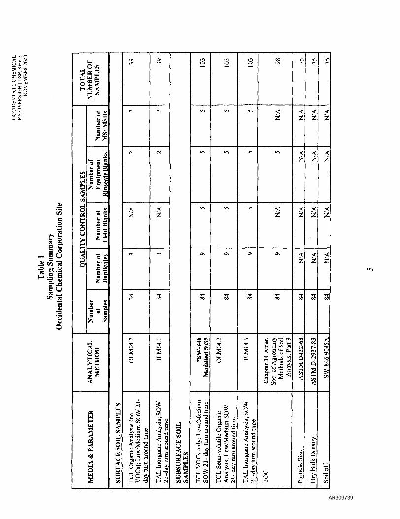
Table 1 of the FSP summarizes the analytical methods and QC samples required for eachmedia to be sampled. Contract-required quantitation limits as specified in the CLP SOW willbe used.
13 AR309726

OCCIDENTAL CHEMICALRA OVERSIGHT QAPP, REV 3
NOVEMBER 2000
2.3 SAMPLE HANDLING AND CUSTODY REQUIREMENTS
Samples collected from the Occidental Chemical site will be handled in accordance with theTetra Tech SOPs listed in the FSP. The Tetra Tech SOPs specify sample handlingprocedures that conform to CLP protocols. These procedures describe protocols for: CLPsample analytical scheduling, use of CLP tracking documents (sample tags, sampleidentification numbers, Traffic Report/Chain of Custody Forms, EPA Shipping Logs, etc.),sample packing, shipping, and shipment reporting requirements. Tetra Tech SOP 605summarizes the bottles, holding times, and preservation requirements for the samplesproposed for collection in the RA Oversight as specified in the Sampler's Guide to the CLP(EPA/540/R-96/032) and the EPA Region III User's Guide for Acquiring AnalyticalServices.
2.4 ANALYTICAL METHODS REQUIREMENTS
For the Occidental Chemical RA Oversight project, samples will be analyzed forlow/medium concentration EPA Target Compound List (TCL) volatile organic compounds,TCL semi-volatile organic compounds, Target Analyte List (TAL) metals, total organiccarbon (TOC), grain size, dry bulk density, and soil pH as summarized on Table 1 of theFSP. The quantitation limits for these analysis are defined in the CLP SOW. For the TOCsoil analysis, the quantitation limit will be 50 mg/kg. The analyses will be performed inaccordance with the most recent EPA Control Laboratory Program (CLP) Statement of Work(SOW).
2.5 QUALITY CONTROL REQUIREMENTS
Data quality shall be assessed for both sampling and analysis efforts using the five basic dataquality indicators described in Section 1.7.4: completeness, comparability,representativeness, precision, and accuracy.
In genera], the data quality assurance requirements for all laboratory-derived analyticalmeasurements will be the responsibility of the CLP laboratory and EPA. Project assessmentand oversight procedures are described in Section 3.0 of this QAPP.
2.6 EQUIPMENT REQUIREMENTS
2.6.1 Inspections
Periodic regular inspection of equipment and instruments is needed to assure the satisfactoryperformance of the systems. Equipment to be used during the sampling event is listed, in theappropriate SOPs. Before any piece of sampling or measurement equipment is taken into thefield, it will be inspected to ensure the following: it is adequate for the task to be performed,all necessary parts of the equipment are intact, and it is in working order. In addition,equipment will be visually inspected prior to its use. Broken equipment will be tagged "DONOT USE" and returned to the Tetra Tech office to receive the necessary repairs, or will bedisposed. Backup field equipment will be available during all field activities in the event ofan equipment breakdown.
14 AR309727

OCCIDENTAL CHEMICALRA OVERSIGHT QAPP, REV 3
NOVEMBER 2000
2.6.2 Maintenance
The objective of preventive maintenance is to ensure the availability and satisfactoryperformance of the measurement systems. All field measurement instruments will receivepreventative maintenance in accordance with the manufacturer's specifications.
2.7 INSTRUMENT CALIBRATION AND FREQUENCY
Periodic regular calibration of specific instruments is needed to assure the satisfactoryperformance of the systems. Calibration procedures and preventative maintenance to be usedon field equipment during the Occidental Chemical RA Oversight project are presented in theFSP (Tt SOP 203). All calibration and maintenance activities (and anomalies) are noted inthe field documentation (Tt SOP 101). The SOPs are included in Attachment 1 of the FSP.
2.8 REQUIREMENTS FOR INSPECTION AND ACCEPTANCE OF SUPPLIES ANDCONSUMABLES
Supplies and consumables are those items necessary to support the sampling and analyticaloperation, including but not limited to: bottles, calibration gases, hoses, decontaminationsupplies, preservatives, various types of water (potable^ deionized, organic-free, etc.). Uponreceipt of supplies, the Tt/B&V Site Manager will ensure that types and quantities of suppliesreceived are consistent with what was ordered and what is indicated on the packing list andinvoice for the material. The supplier will be contacted immediately if any discrepancy isidentified.
2.9 REQUIREMENTS FOR ACCEPTANCE OF OUTSIDE DATA
Comparison of data collected during this field effort to historic data collected during theprevious investigations will be a qualitative assessment only.
2.10 DATA MANAGEMENT
Tt/B&V employs a variety of methods to prepare, review, approve, use, control, revise, store,and maintain documents and records. The procedures to be used for the Occidental ChemicalRA oversight project are described in detail in Section 8.0 of the RAC III QMP.
2.10.1 Field Data
Management of data acquired in the field such as physical or chemical measurements, will beperformed in accordance with Section 8.7.9 of the RAC III QMP. The Tt/B&V Site Managerwill assign a field team leader to supervise the field work and provide quality control of theseactivities.
2.10.2 Laboratory Data
Laboratory data will be managed in accordance with Section 8.7.10 of the RAC HI QMP.All reports from the laboratory will be reviewed to verify that the data are consistent with
15 AR309728
OCCIDENTAL CHEMICALRA OVERSIGHT QAPP, REV 3
NOVEMBER 2000
project requirements, the laboratory has reported the results in the proper units, and the dataare in compliance with applicable protocol.
3.0 ASSESSMENT/OVERSIGHT
3.1 ASSESSMENTS AND RESPONSE ACTIONS
The Program Manager or Tt/B&V Site Manager may periodically request that audits andfield reviews are conducted to verify that quality assurance procedures are being consistentlyand correctly applied and that, when correctly applied, they are effective. The followingtypes of audits and the field review are described in detail in the Section 9.0 of the RAC IIIQMP:
(1) Performance Audits.(2) System Audits.(3) Client Audits.(4) Consultant or subcontractor quality assurance activity audits.
Performance and system audits are audits of the performance of field activities and of theoverall operating system under which the field activities are performed. Laboratory auditingis performed by the EPA through the CLP.
Performance audits, system audits, and consultant or subcontractor audits will be performedto (1) determine that a QA program has been developed and documented in accordance withspecified requirements; (2) verify by examination and evaluation of objective evidence thatthe documented program has been implemented; (3) assess the effectiveness of the QAPP;(4) identify any nonconformances, and (5) verify correction of identified deficiencies.
The Tt/B&V Site Manager and Tt/B&V QA Manager will be responsible for initiating audits,selecting the audit team, and overseeing the audit implementation of field operations andlaboratory services. Audits will be performed at a frequency commensurate with the statusand importance of the activity.
3.1.1 Performance Audits
Performance audits are used to determine quantitatively the accuracy of measurement datathrough the use of field blank and duplicate samples. The performance audits involve reviewof field QC samples and field documentation to ensure the following:
(1) Field duplicate samples are analyzed at a frequency equal to at least 5 percent of thetotal number of samples analyzed, and field blanks are analyzed daily.
(2) Field duplicates have a maximum relative percentage difference (RPD) of 20 percent,and no signs of contamination are present in the field blanks.
(3) All data are validated before being used.
16 AR309729
OCCIDENTAL CHEMICALRA OVERSIGHT QAPP, REV 3
NOVEMBER 2000
(4) All field activities are properly documented in the field logbooks, and all samples arerecorded on chain-of-custody forms.
3.1.2 Systems Audits
System audits will review the total data generation process, which includes on-site reviews ofthe field operational systems and physical facilities for sampling. These audits are performedannually and when required by specific projects.
3.1.3 Audit Procedure
This procedure provides requirements and guidance for performing internal audits to verifycompliance with the elements of the QAPP.
A field audit of sampling events will be performed when deemed appropriate by the Tt/B&VQA Manager and Site Manager. The field sampling team personnel may be notified prior tothis audit, or the audit may be performed spontaneously.
Audit checklists will be prepared by the auditor. The checklist is intended for use as a guideand will not restrict the audit investigation when findings raise further questions that are notspecifically included in the checklist. These selected elements of the QAPP will be auditedto the depth necessary to determine whether they are being implemented effectively.
Conditions requiring immediate corrective action will be reported immediately to the fieldsampling supervisor and any other appropriate personnel.
At the conclusion of the audit, a post-audit conference will be held with the field samplingsupervisor to present audit findings and clarify any misunderstandings. Audit findings willbe concisely stated by the auditor in the List of Findings for Post-Audit Conference. Thefindings will be acknowledged by the field sampling or designated representative by signingthe List of Findings.
3.2 OUT OF CONTROL EVENTS
An out-of-control event is defined as any deviation from the sampling and analysisprocedures due to circumstances and/or conditions beyond the samplers or laboratory control.Some examples of these conditions and circumstances are as follows: (1) health and safetysituations, such as explosive atmosphere conditions; (2) unforeseen site conditions, such asbedrock at shallow depth at a boring location; and (3) laboratory conditions, such as poweroutages that may cause a loss of data.
3.2.1 Responses to Out-of-Control Events
The Tt/B&V Site Manager will be responsible for identification of an out-of-control eventfield. The EPA will be responsible for the identification of these events in the laboratory.Upon recognition or identification of an out-of-control event in the field, the Tt/B&V SiteManager will stop work and shift to a different, unaffected activity/task if possible. The Site
17 AR309730
OCCIDENTAL CHEMICALRA OVERSIGHT QAPP, REV 3
NOVEMBER 2000
Manager will notify, as soon as possible, the appropriate field personnel. The field personnelwill have the responsibility of providing documentation of the event and will coordinate andrecommend corrective actions.
In the event an out-of-control event occurs in the laboratory, BSD will notify the EPA ProjectManager who will determine the appropriate course of action.
Corrective actions for the examples indicated above, may include: (1) ventilation of the workarea, (2) probing of the area for subsurface conditions, followed by repositioning orelimination of the test boring, and (3) analysis of a breakage sample or QA/QC sample toprevent loss of data.
3.2.2 Re-evaluation of Laboratory Control Limits
Re-evaluation of laboratory control limits after an out-of-control event will be theresponsibility of the RQAM in coordination with the EPA Project Manager and the Tt/B&VSite Manager. Wherever possible, the breakage sample and/or QA/QC samples will beanalyzed in place of the matrix sample using the laboratory control limits that apply to thematrix samples.
3.2.3 Documentation of Out-of-Control Events and Corrective Actions
The field personnel will be responsible for the correct and complete documentation of out-of-control events and corrective actions taken. For each event-corrective action, a letterdescribing the out-of-control event and the corrective actions taken will be prepared by theTetra Tech field personnel and submitted to the EPA PM.
3.3 REPORTS TO MANAGEMENT
A primary feature of effective quality assurance is reporting the results of quality assuranceactivities. Quality Assurance reporting procedures are presented in detail in the Section 10.0of the RAC III QMP. Audit reports, response and follow-up are further described below.
3.3.1 Audit reports
After each audit, an audit report will be prepared by the auditor. The report will include thefollowing:
(1) Description of the audit scope.(2) Identification of the audit team.(3) Persons contacted during pre-audit, audit, and post-audit activities.(4) A summary of audit results, including an evaluation statement regarding the
effectiveness of the QAPP elements that were audited.(5) Details of findings and program deficiencies will be reported on an Audit Findings
Report (AFR). Each finding and program deficiency will be identified and describedin sufficient detail to ensure that corrective action can be effectively carried out by theproject organization.
18 AR309731
OCCIDENTAL CHEMICALRA OVERSIGHT QAPP, REV 3
NOVEMBER 2000
(6) Recommendations for correcting the findings or improving the QAPP.
The audit report will be addressed to the Site Manager with a copy to responsible partieswithin Tt/B&V (i.e., Program Manager) and others as appropriate.
3.3.2 Response
The Site Manager or designated representative will respond to the APR by completing aCorrective Action Reply. The response will be completed within 20 days of receipt and willclearly state the corrective action for each finding, including action to prevent recurrence andthe date the corrective action will be completed.
3.3.3 Follow-Up Action
Follow-up action will be performed by the Tt/B&V QA Manager:
(1) Evaluate the adequacy of the response.
(2) Ensure that corrective action is identified and scheduled for each finding.
(3) Confirm that corrective action is accomplished as scheduled.
Follow-up action may be accomplished through written communications, re-audit, or otherappropriate means and will be documented in accordance with Section 10.0 of the RAC IIIQMP. When all corrective actions have been verified, a memo will be sent to the SiteManager to satisfy the close-out requirement of the audit with copies to the responsibleparties and others, as appropriate.
4.0 DATA VALIDATION AND USABILITY
The responsibility for the validation of laboratory data generated in support of siteinvestigations in EPA Region HI has been assigned to the Environmental Services AssistanceTeam (ESAT) with oversight by the Quality Assurance Team of the EPA's Region III, Officeof Analytical Services and Quality Assurance (QASQA) in Fort Meade, Maryland. InternalEPA data validation protocols are not subject to evaluation by RAC contractors. Should anindependent data validation effort be desired by the EPA, such can be provided by Tt/B&Vor qualified subcontractor (refer to the Tt/B&V Plan for the Delivery of Analytical Services).
Consequently, the following discussion has been limited to addressing the validation andverification of non-laboratory data and field mobile laboratory screening data.
19 AR309732

OCCIDENTAL CHEMICALRA OVERSIGHT QAPP, REV 3
NOVEMBER 2000
4.1 REQUIREMENTS & METHODS FOR DATA REVIEW, VALIDATION, ANDVERIFICATION
As stated above, validation of laboratory data will be conducted directly by EPA. All datawill be reviewed in accordance with the M2 and IM1 level of review as described in theRegion III guidance document titled "Innovative Approaches to Data Validation Guidance"dated June 1995.
It should be noted that field parameter measurement data (i.e. pH, dissolved oxygen,temperature, etc.) will not be subject to formal validation, but will be reviewed with respectto applicable calibration procedures and reasonableness.
4.2 RECONCILIATION OF RESULTS WITH PROJECT DATA QUALITYOBJECTIVES
As a result of the validation and verification effort, certain data will be eliminated orrestricted in their usability. Section 1.7 of this QAPP describes the processes for assessmentof accuracy, precision, and completeness. The results of the assessment will be compared tothe DQOs and the acceptable limits of uncertainty. If the stated DQOs are not met,additional sampling, resampling or limitations on the use of the data may result.
20 AR309733

OCCIDENTAL CHEMICALRA OVERSIGHT FSP, REV 3
NOVEMBER 2000
Field Sampling PlanRevision 3
Remedial Action Oversight
Monitoring Well Installation, Background Soiland Ground-Water Sampling, and
Earthen Lagoon Surface Soil Sampling
Occidental Chemical SitePottstown, Pennsylvania
Work Assignment No. 009-RXBF-03S9Contract 68-S7-3002
November 30, 2000
Prepared by:
Tetra Tech/Black & Veatch
Prepared for:
U. S. Environmental Protection Agency, Region IIIPhiladelphia, PA
AR309734
OCCIDENTAL CHEMICALRA OVERSIGHT FSP, REV 3
NOVEMBER 2000
TABLE OF CONTENTS
1.0 SITE BACKGROUND 1
2.0 SAMPLING OBJECTIVES 1
3.0 SAMPLE LOCATION AND FREQUENCY 13.1 BACKGROUND MONITORING WELL INSTALLATION 1
3.1.1 Well Installation Procedure 33.1.2 Well Development 4
3.2 GROUND-WATER SAMPLING 43.3 SOIL SAMPLING 73.4 SURFACE WATER SAMPLING 12
4.0 SAMPLING DESIGNATIONS 13
5.0 SAMPLING EQUIPMENT AND PROCEDURES 14
6.0 SAMPLE HANDLING AND ANALYSIS 15
FIGURE 1 WELL AND BACKGROUND SOIL SAMPLE LOCATIONS 2FIGURE 2 HISTORIC BACKGROUND SOIL SAMPLING LOCATIONS 8FIGURE 3 EARTHEN LAGOON SURFACE SOIL SAMPLING LOCATIONS 10FIGURE 4 EARTHEN LAGOON SUBSURFACE SOIL SAMPLE LOCATIONS 11
TABLE 1 SAMPLING SUMMARY 5&6
ATTACHMENT 1 STANDARD OPERATING PROCEDURESATTACHMENT 2 SCHEMATIC MONITORING WELL DETAIL
AR309735
OCCIDENTAL CHEMICALRA OVERSIGHT FSP, REV 3
NOVEMBER 2000
1.0 SITE BACKGROUND
A full description of the Occidental Chemical site background is presented in Section 1.0 of thePRP's Final Remedial Design for Bedrock Groundwater, June 1997 (Bedrock GW RD).
2.0 SAMPLING OBJECTIVES
This Field Sampling Plan contains the specific technical approaches being proposed to collect dataof adequate content, quality, and quantity to support the EPA's review of clean-up levels for theearthen lagoons. The review of clean-up levels is being performed by EPA in response to OccidentalChemical's request for Explanation of Significant Differences (BSD) to revise the clean-up levelsfor the earthen lagoons. The primary objective of this effort is to determine and evaluate backgroundconcentrations as well as determine the current quality of surface soil and surface water in theearthen lagoon areas.
The purpose of the field activities is to collect analytical data from background locations forcomparison to existing site soil and ground-water data to establish revised clean-up levels for theearthen lagoons. Additional earthen lagoon surface/subsurface soil and water samples will also becollected to assess the current conditions of the lagoons. The revised clean-up levels will bedeveloped using EPA's Soil Screening Guidance dated May 1996, and will include the developmentof risk-based ground-water clean-up levels.
3.0 SAMPLE LOCATION AND FREQUENCY
Field sampling is proposed to be performed in support of RA Oversight. Field sampling is to includethe collection of background soil and ground-water samples and the collection of surface/subsurfacesoil and water samples for the earthen lagoons.
Methods for field documentation and sample handling are described in standard operatingprocedures (SOPs) developed to ensure sample quality (integrity and representativeness). Thesegeneral procedures are listed in Section 5.0, Sampling Equipment and Procedures. Completeapplicable SOP descriptions are contained in Attachment 1.
3.1 BACKGROUND MONITORING WELL INSTALLATION
One new bedrock well, to be designated BR-17, will be installed to supplement two existing backgroundwell locations PW-1R and TB-9. BR-17 is to be located at the northeast comer of the site, within theopen grass area adjacent to the site's front entrance (Figure 1). This location was chosen because it isupgradient of the main portion of the plant under both pumping and non-pumping conditions of therecovery well system.
Existing background wells PW-1R and TB-9 were both completed as open rock wells with total depthsof 513 feet and 258 feet, respectively. Based on geologic data provided in the site RI, the highestpermeabilities in the bedrock unit across the site exist within the sandstone units of the Brunswick
1AR309736
OCCIDENTAL CHEMICALRA OVERSIGHT FSP, REV 3
NOVEMBER 2000
Formation. The RI also stated that permeabilities and transmissivities are greater along the strikeof the bedrock units, which is northeast to southwest.
Well logs for well PW-1R, located near the proposed new background well location, show that thefirst water bearing fracture zone exists within a sandstone unit at approximately 175 feet belowgrade. PW-1R was drilled to a depth of 550 feet and, therefore, intercepts numerous fracture zones.BR-17 will be drilled to the first water-bearing fracture zone so that background ground-water datacan be collected specifically for the shallow bedrock aquifer.
BR-17 will be drilled and installed in accordance to Tt/B& V SOP #309. The following sections includea general description of the well drilling procedures and specifications to be used at the OccidentalChemical Coiporation site. No soil samples will be collected for laboratory analyses during the wellinstallation task. However, characterization of well drilling cuttings may be required for dispositionof cuttings, depending on future coordination meetings with Occidental Environmental personnel.
3.1.1 Well Installation Procedure
The boring for the new bedrock well BR-17 will be drilled using an air rotary drill rig capable of drillingup to 8-inch diameter boreholes in bedrock to a maximum depth of approximately 200 feet belowground surface. A 12-inch diameter borehole will be drilled through the unconsolidated zone (estimatedmaximum of 20 feet thick) and five feet into the competent bedrock. A 10-inch ID steel casing will thenbe installed with the outside annulus sealed with a cement/bentonite mixture (95% to 5% dry weight).Twenty-four hours of set time shall be allowed before additional drilling can be performed at the samelocation. After 24 hours, an 8-inch diameter borehole will be drilled to the first major water bearingfracture zone, which based on geologic data collected during the RI may require 180 additional feet ofdrilling.
The well will be constructed with four-inch diameter Schedule 40 Type 1 PVC well casing and wellscreen. It is anticipated that a total of 40 feet of screen and 160 feet of casing will be used to constructthe bedrock well. The well screen will be placed so as to intercept the water bearing fracture zone, andthe slot size of the screen for the bedrock well will be 0.040-inch. An 8 to 12 sand pack mesh, silicagravel filter pack will be installed in the annular space from the base of each boring to approximatelytwo feet above the top of the screens. A minimum two-foot bentonite pellet seal will be placed abovethe sand pack to seal the permeable zone. The remainder of the annulus will be tremie-grouted toground surface with a cement-bentonite mixture containing 5% bentonite (dry weight). The wells willbe finished with a flush mount protective casing. A schematic drawing of the well constructionspecifications is included in Attachment 2.
The handling and disposition of soil cuttings and drill water will be determined upon discussion withOccidental environmental personnel once a coordination meeting with them can be arranged.
AR309737
OCCIDENTAL CHEMICALRA OVERSIGHT FSP, REV 3
NOVEMBER 2000
3.1.2 Well Development
The new well (BR-17) will be developed according to the procedures described in either Tt/B&VSOP #311 or #312. The specific well development procedure will be determined in the field and basedon the well yields attained during the installation of the wells. All purged ground-water will bedischarged to the ground in the vicinity of the well.
3.2 GROUND-WATER SAMPLING
The bedrock monitoring wells will be sampled using standard well sampling procedures performedin accordance with Tt/B&V SOP #313 (see Section 5.0). The shallow overburden wells will besampled using "low flow" procedures performed in accordance with Tt/B&V SOP #314 (see Section5.0) because the water bearing zone of the overburden wells is vertically thin, which allows a pumpto be set, with relative assurance, within the water bearing portion of the formation. A summary ofthe total number of samples to be collected and their corresponding analytical parameters is includedin Table 1.
Number and Locations of Ground-Water Samples: Samples of ground water will be collectedfrom three existing overburden wells (OW-6A, OW-9, and OW-12), two existing bedrock wells(PW-1R and TB-9), and the newly installed bedrock well BR-17.
The criteria for selecting the three overburden background well locations are as follows: (1) theproposed overburden wells are located within the alluvial aquifer, though it is notable that thealluvial deposits are all downgradient of the plant area; (2) the wells are "upgradient" of the earthenlagoons under both pumping and non-pumping conditions as determined during the RI andillustrated on Figures 3-11 and 3-12 of the RI; and (3) no VOCs (specifically TCE and VCM) weredetected during either pre-RI or RI ground-water sampling events.
Bedrock wells P W-1R and TB-9 had been used as background locations during the RI. These wellswill be resampled to collect updated ground-water quality data.
The first round sampling results will be evaluated to determine if the ground-water data collectedfrom the three overburden wells is representative of "background" ground-water conditions or hasbeen impacted by other site sources (e.g., active and closed landfills). Based on this evaluation, anadditional two or three overburden wells may be sampled during the second and third round ofground-water sampling to replace or to supplement the existing ground-water sampling locations.
Sample Frequency: The frequency of ground-water sampling is three rounds approximately threemonths apart. It is anticipated that a single round of ground-water sampling will take two to three(including paperwork) days to complete using one sampling crew.
Analytical Parameters: The ground-water samples will be submitted to the EPA's ContractLaboratory Program (CLP) or Office of Analytical Services and Quality Assurance (OASQA) forRoutine Analytical Services (RAS). All ground-water samples will be submitted for the following
AR309738
<>§O tu IN
Q >GO
S o
03 13
.s a"s v
a<u3w
b,O 01
2 Waj§ ,£
|
— i CA
t/3WKj
1c/ljjjOS1-JL
Ou
S
J2O1
0 £
M ^Q
"f ^
*S a »
jo a, o»S "3 "«Z w S
^ M*o ^<u -2A paS T3
2 3ta
. -4— >
_g .3S "33 3
Iq <«
•S <- "3= « Hz </]
AN
AL
YT
ICA
LM
ET
HO
DM
ED
IA &
PA
RA
ME
TE
R
| SU
RFA
CE
SO
IL S
AM
PLE
S
ON
O)
(N
<
z.
m
Tf
OL
M04
.2T
CL
Org
anic
Ana
lysi
s (no
VO
Cs)
; L
ow/M
ediu
m S
OW
21-
day
turn
aro
und
time
CO
(N
(N
^^jg
ro
S
i
TA
L I
norg
anic
Ana
lysi
s; S
OW
21 -d
ay t
urn
arou
nd ti
me
SUB
SUR
FAC
E S
OIL
SAM
PLE
S
2" — *
in
m
in
ON
oo
ve vt
Ji? 'OU3 V* ta
1
TC
L V
OC
s on
ly; L
ow/M
ediu
mSO
W 2
1 -
day
turn
aro
und
time
o
•n
•n
•n
ON
Tfoo
OL
M04
.2T
CL
Sem
i-vo
latil
e O
rgan
icA
naly
sis;
Low
/Med
ium
SO
W21
- da
y tu
rn a
roun
d tim
e
o^^
m
•n
•n
ON
TfOO
ILM
04.1
1.fi< 30 0
fl ^(Q r^00 C
S 3
ooO\
2
in
^
^
ON
oo
Cha
pter
34
Am
er.
Soc.
of A
gron
omy
Met
hods
of
Soil
Ana
ysis
, Par
t 3
r-
$
|
<
g
^"
TfOO
S00
u$JS"u
1CU
in
|
|
2
y
00
AST
M D
-293
7-83
1 D
ry B
ulk
Den
sity
>nr-
g
|
12
^
^
Tf
So\VO
OO
on
ffiD
'oC/3
AR309739

c >GO
ao
o&o
dou. en- J|
fl0)
O t«
H f*^3 </)Z
COWJ?^
^CA
Op£HzOu
3O1
«M 1/10 Q£ M
"3 a J
1113 a- S
Z W _t5
O g
OJ "js a
^E
o 2^ **W y
S o3 aZ Q
4> S
1*15 «Z co
3sH 33>5*M [J
^
tf
ME
DIA
& P
AR
AM
ET
B
aaH
>WO. T
M
5cnW
S
COW
di^
GR
OU
ND
WA
TE
R S
AI
fi
m
vo
vO
^
X 00CO '"T*(U II
§••305 0
VO k-rn
OL
M04
.2
3'& ^
Full
TC
L O
rgan
ic A
naly
sL
ow/M
ediu
m S
OW
21-
dar
ound
tim
e
m
fl
vo
VO
m
X oou II'S"3S ato 3« O
VO "-m
S|
£00
TA
L I
norg
anic
Ana
lysi
s;2
1 -d
ay t
urn
arou
nd t
ime
ro
m
vo
^
X ooCO ^u II11lim
1LM
04.1
Dis
solv
ed
£oCO
TA
L I
norg
anic
Ana
lysi
s;2
1 -d
ay tu
rn a
roun
d tim
e
oo
^^
1
^|7(
^/^H
00^^
Fiel
dea
sure
men
t
IS,
„
s
pH, t
empe
ratu
re, c
ondu
ctre
dox,
dis
solv
ed o
xyge
n
-1
S
1 SU
RFA
CE
WA
TE
R S
A
^
__^
-
—
•
OL
M04
.2
e£ &
Ful
l T
CL
Org
anic
Ana
lys
Low
/Med
ium
SO
W 2
1- d
arou
nd t
ime
r-
t ,
— •
-
• -
i|
^SI
TA
L I
norg
anic
Ana
lysi
s;2
1 -d
ay tu
rn a
roun
d tim
e
^
— -i
-
-
^"
§1
OC/3
TA
L I
norg
anic
Ana
lysi
s;2
1 -d
ay tu
rn a
roun
d tim
e
„.
^^
^
<2
<V^
^Fi
eld
easu
rem
ent
2
^
5:
pH, t
empe
ratu
re, c
ondu
ctre
dox,
dis
solv
ed o
xyge
n
S3 J
.2 .1 "a.
^ S o iS s «
TT5 i5 IB S
AR309740
OCCIDENTAL CHEMICALRA OVERSIGHT FSP, REV 3
NOVEMBER 2000
parameters: low/medium concentration TCL volatile organic compounds, TCL semi-volatile,compounds, TAL dissolved metals, and TAL total metals.
In addition, screening data will be collected in the field during ground-water sampling using a YSI600 XL Water Quality Monitoring System. The water quality parameters to be measured during theground-water sampling will include temperature, conductivity, oxidation-reduction potential (ORP orEh), pH, and dissolved oxygen.
QA/QC samples to be analyzed during each ground-water sampling event will include trip blanks (1per volatiles shipping container), equipment rinseate and field blanks (1 each per 20 samples collectedor one each per day, whichever is more frequent), blind duplicates (1 per 10 samples collected), andextra volume for matrix spike/spike duplicate (MS/MSD) analysis. In addition, temperature blanks willbe included in each sample shipping container. The trip blanks will be analyzed for TCL volatileorganic compounds only. All the other QA/QC samples will be analyzed for TCL volatile organiccompounds, TCL semi-volatile compounds, TAL total metals, and TAL dissolved metals.
3.3 SOIL SAMPLING
Two types of soil sampling will be performed: background surface and subsurface soil sampling andearthen lagoon surface and subsurface soil sampling. All sampling equipment will bedecontaminated between each use as described in Tt SOP 501. All excess drill cuttings during SPTborings will be returned to the borehole after sampling is complete at each location. A Tetra Techgeologist will supervise all subsurface and surface soil sampling activities. A summary of the totalnumber (approximate) of samples to be collected and their corresponding analytical parameters isincluded in Table 1.
Background Soil Sampling
One surface soil sample and up to three subsurface soil samples will be collected from each of the10 background boring locations depicted on Figure 1.
Background subsurface soil samples will be collected using Standard Penetration Test (SPT) Boringsin accordance with Tt/B&V SOP #303. SPT split-spoon sampling will be performed continuouslyat each location. The three subsurface soil samples to be collected from each boring will be fromthree separate soil horizons. The first sample will be collected from the shallow dark brown to blackorganic loam identified between 0 to 5 feet during the RI subsurface soil sampling activities. Thesecond sample will be collected from the coal fine layer (if present) identified between 5 to 10 feetbelow grade during RI subsurface soil sampling activities. The third sample will be collected fromthe top of the gray/brown, clayey silt/silty clay unit located immediately below the coal fine layer.
A surface soil sample will also be collected from each of the same 10 background locations inaccordance with Tt/B&V SOP #407. Each surface soil sample will be collected at a depth of 6inches. For reference, background soil boring locations used during the RI are shown on Figure 2.
AR309741
s
1-S
Offslte Background Sols
Onsite Background Soil*
HISTORICBackground Soil Sampling LocationsAR309742
AR309743
OCCIDENTAL CHEMICALRA OVERSIGHT FSP, REV 3
NOVEMBER 2000
Earthen Lagoon Soil Sampling
Surface soil samples will be collected from the earthen lagoons at locations depicted on Figure 3 .A total of 24 surface soil composite samples will be collected from the earthen lagoon area, or 6composite samples each from the northwest, northeast, southwest, and southeast lagoons. Each ofthe four lagoons is considered an "exposure area", measuring approximately one-half acre in size.Each surface soil composite sample shall be comprised of four individual samples collected at adepth of 6 inches at random locations depicted on Figure 3. Note that this sampling rationale isbased on the 1996 USEPA Soil Screening Guidance, as requested by EPA. Surface soil samplecompositing will be performed in accordance with Tt/B&V SOP #409.
Subsurface soil samples will be collected using Standard Penetration Test (SPT) Borings inaccordance with Tt/B&V SOP #303. A total often SPT borings will be performed continuouslyat the random locations depicted on Figure 4 to a depth where ground water or bedrock isencountered, which ever is shallower. Six borings will be performed within the northwest andsouthwest lagoons (three borings per lagoon). The northwest and southwest lagoons are the lagoonswhere the majority of PVC sludge had been previously removed and relocated. Four borings willbe performed within the southeast and northeast lagoons (two borings per lagoon). In addition tothe PVC sludge originally contained in these lagoons, the southeast and northeast lagoons alsocontain the PVC sludge that was previously relocated from the northwest and southwest lagoons.
Subsurface split-spoon sampling for each of the boring locations shall begin at the surface and beperformed continuously in 2-foot split-spoon intervals. One sample shall be collected for each 2-footsplit-spoon sample interval to the final boring depth. Samples shall be representative of the entire2-foot interval. The representative interval length shall be recorded for each sample.
Sample Frequency: The frequency of soil sampling is one round of sampling.
Analytical Parameters: The soil samples will be submitted to the EPA's Contract LaboratoryProgram (CLP) or OASQA for Routine Analytical Services (RAS).
All surface soil samples will be submitted for the following parameters: TCL semi-volatilecompounds, and TAL metals. Surface soil samples will not be submitted for TCL volatiles, asvolatiles are not expected to remain at the surface for an extended period of time.
All subsurface soil samples will be submitted for the following parameters: TCL volatile organiccompounds, TCL semi-volatile compounds, and TAL metals. In addition, the subsurface soilsamples will be submitted for non-CLP analysis through the Delivery of Analytical ServicesProgram (DAS) for: total organic carbon (TOC), particle size, dry bulk density, and pH.
It should be noted that TCL VOC subsurface soil samples shall be collected using Option 1 (EnCoresampling device, or equivalent) of the CLP Sample Collection Guidelines for Volatiles in Soil by CLP-Modified SW-846 Method 5035. Due to a 24-hour holding time, EnCore samples (accompanied
AR309744
Io
$ -CO
E ^ >fc <D — C
» > "S E » I« =5 r> S 3|-5I^1S.t "^ ^ > o ? •
& •}= -° m C."S> — o % £
Msl^:
10 O) o O t -rj Q-
£ "S ra ^S fjj-2 EO o S ® "
""III!!x:i o-xi g-^ U = g
li
01
oCu.
AR309745

AR309746

OCCIDENTAL CHEMICALRA OVERSIGHT FSP, REV 3
NOVEMBER 2000
with moisture content samples) are to be immediately delivered to the laboratory. Upon receipt ofsample by laboratory, laboratory is to immediately transfer the soil into preserved sample vials.
QA/QC samples to be analyzed during the soil sampling event will include trip blanks (1 per volatilesshipping container), equipment rinseate and field blanks (1 each per 20 samples collected or one eachper day, whichever is more frequent), blind duplicates (1 per 10 samples collected), and matrixspike/spike duplicate samples (1 each per 20 samples collected). In addition, temperature blanks willbe included in each sample shipping container. The trip blank will be analyzed for TCL volatile organiccompounds only. The equipment rinseate and field blank samples will be analyzed for TCL volatileorganic compounds, TCL semi-volatile organic compounds, and TAL metals. The blind duplicateand matrix spike/spike duplicate samples will be analyzed for TCL volatile organic compounds, TALmetals, TOC, and pH.
3.4 SURFACE WATER SAMPLING
Of the four earthen lagoons at the Oxy site, two of them (southwest and northwest lagoons) currentlycontain surface water. A total of four surface water samples will be collected from these earthenlagoons, two from the southwest lagoon and two from the northwest lagoon. Refer to Figure 3 forthe location of these lagoons. The purpose of the lagoon surface water samples is to provide generalcharacterization of the surface water. Surface water sampling will be performed in accordance withTt SOP #401. A summary of the total number of samples to be collected and their correspondinganalytical parameters is included in Table 1.
Sample Frequency: One round.
Analytical Parameters: The surface water samples will be submitted to the EPA's ContractLaboratory Program (CLP) or Office of Analytical Services and Quality Assurance (OASQA) forRoutine Analytical Services (RAS). All surface water samples will be submitted for the followingparameters: low/medium concentration TCL volatile organic compounds, TCL semi-volatile,compounds, TAL dissolved metals, and TAL total metals.
In addition, screening data will be collected in the field during surface water sampling using a YSI600 XL Water Quality Monitoring System. The water quality parameters to be measured during thesurface water sampling will include temperature, conductivity, oxidation-reduction potential (ORP orEh) andpH.
QA/QC samples to be analyzed during the surface water event will include trip blanks (1 per volatilesshipping container), equipment rinseate and field blanks (1 each per 20 samples collected or one eachper day, whichever is more frequent), blind duplicates (1 per 10 samples collected), and extra volumefor matrix spike/spike duplicate (MS/MSD) analysis. In addition, temperature blanks will be includedin each sample shipping container. The trip blanks will be analyzed for TCL volatile organiccompounds only. All the other QA/QC samples will be analyzed for TCL volatile organic compounds,TCL semi-volatile compounds, TAL total metals, and TAL dissolved metals. The soil water sampleswill be submitted to the EPA's Contract Laboratory Program (CLP) or OASQA for Routine
12AR309747
OCCIDENTAL CHEMICALRA OVERSIGHT FSP, REV 3
NOVEMBER 2000
• A subsurface soil sample collected from 4 to 6 feet at location 2 in the northeast lagoon wouldbe designated as: OXY-SB-NE2(4-6); and
• The second surface water sample collected for the northwest lagoon would be designated asOXY-SW-NW2.
5.0 SAMPLING EQUIPMENT AND PROCEDURES
The SOPs proposed for the performance of the RA Oversight for the Occidental Chemical site arelisted below.
STANDARD OPERATING PROCEDURE LIST
SOPs for Field Documentation
101 Field Logbook and Photographs
SOPs for Equipment Calibration and Maintenance
203 Photovac Microtip III Photoionization Detector207 YSI Model 600 XL Water Quality Monitoring System
SOPs for Subsurface Investigations
301 Field Description of Soils303 Standard Penetration Test Borings/Direct Push Borings309 Monitoring Well/Piezometer Installation311 Surge Block Well Development312 Airlift Surging Well Development Techniques313 Ground-Water Sampling314 Low-Flow Purging and Ground Water Sampling
SOPs for Surface Investigations
401 Surface Water Sampling402 Field Measurement of Water Temperature403 Field Measurement of Water pH404 Field Measurement of Specific Conductance406 Field Measurement of Redox Potential (Eh)407 Surface Soil Sampling409 Sample Compositing
SOPs for Decontamination
501 Small Equipment Decontamination503 Large Equipment Decontamination
14AR309748
OCCIDENTAL CHEMICALRA OVERSIGHT FSP, REV 3
NOVEMBER 2000
505 Decontamination of Personnel
SOPs for Sample Management
601 Analytical Services RAS and DAS Requests605 Sample Containers, Volumes, and Preservatives607 Sample Preservation Aqueous Samples608 QA/QC Check of Sample pH609 QA/QC Samples611 Sample Tags613 Chain-of-Custody Forms615 Traffic Report & Chain of Custody Forms621 Sample Shipping623 Reporting Sample Shipment
6.0 SAMPLE HANDLING AND ANALYSIS
Samples collected from the Occidental Chemical site will be handled in accordance with the SOPslisted in Section 5.0 under the heading of Sample Management (the SOP#600 series).
Samples collected for submission through the Contract Laboratory Program (CLP) will be handledaccording to the specific CLP protocols: CLP sample analytical scheduling, use of CLP trackingdocuments (sample tags, sample identification numbers, Traffic Report/Chain of Custody Forms,EPA Shipping Logs, etc.), sample packing, shipping, and shipment reporting requirements. SOP#605summarizes the bottleware, holding times, and preservation requirements for the samples proposedfor collection in the RD field activities as specified in the Sampler's Guide to the CLP (EPA/540/R-96/032) and the EPA Region III User's Guide for Acquiring Analytical Services (June, 1999).
15AR309749
OCCIDENTAL CHEMICALRA OVERSIGHT FSP, REV 3
NOVEMBER 2000
ATTACHMENT 1STANDARD OPERATING
PROCEDURES
AR309750
TETRA TECH SOP #101REV. #7
February, 1995PAGE 1 OF 2
FIELD LOGBOOK AND PHOTOGRAPHS
A. PURPOSE/SCOPE:
To produce an accurate and reliable record of all field activities, including field observations,sample collection activities, etc.
All pertinent field survey and sampling information shall be recorded in a logbookduring eachday of the field effort. A logbook will be assigned to each field task and will have a uniquedocument control number. The logbook will be bound and will have consecutively numberedpages.
In addition to keeping a logbook, photographs provide a physical record to augment the fieldworker's written observations. They can be valuable to the field team during futureinspections, informal meetings, and hearings. Photographs should be taken with a camera-lens system having a perspective similar to that afforded by the naked eye. A photographmust be documented if it is to be a valid representation of an existing situation.
B. EQUIPMENT/MATERIALS:
Bound Field Book (with waterproof paper), Indelible Ink Pens, 35 mm Camera with 50 mmlens, 100 ASA 35 mm Film,
C. PROCEDURE:
1. At a minimum, entries in a logbook shall include:
• Date and time of starting work;
• Names of all personnel at site;
Purpose of proposed work effort;
• Sampling equipment to be used and calibration of equipment;
• Description of work area
Location of work area, including map reference;
• Details of work effort, particularly any deviation from the field operations plan orstandard operating procedures;
• Field observations;
• Field measurements (e.g., pH);
• Field laboratory analytical results;
AR309751
TETRA TECH SOP #101 »<REV. #1
February, 1995PAGE 2 OF 2 (
• Personnel and equipment decontamination procedures; and ,
• Daily health and safety entries, including levels of protection.
• Type and number of samples; j
• Sampling method, particularly deviations from the standard operating procedures;
• Sample location and number;
Sample handling, packaging, labeling, and shipping information (including jdestination). «'
2. For each photograph taken, several items shall be recorded in the field logbooks: p
• Date and time;
Name of photographer, i.
• General direction faced and description of the subject; |
• Sequential number of the photograph and roll number.
3. Each day's entries will be initialed and dated at the end by the author, and a linewill be jdrawn through the remainder of the page.
4. Strict custody procedures shall be maintained with the field logbooks. While being used |in the field, logbooks shall remain with the field team at all times. Upon completion ofthe field effort, the logbook shall be placed in the project file in the Tetra Tech, Delaware »office. j
D. QA/QC: .
All entries in the logbook shall be made in indelible ink. All corrections shall consist of singleline-out deletions that are initialed.
The field task leader shall be responsible for ensuring that sufficient detail is recorded in thelogbooks, and shall review the site logbooks daily.
E. SPECIAL CONDITIONS: '
Once a roll of film is developed, the slides or prints will be placed in task files in the field office jPhotographic information from the logbooks will be photocopied and placed in the file 'accompanying the slides or prints.
F. REFERENCES: '
None. '
AR309752
TETRA TECH SOP #203REV. #2
July, 1997PAGE 1 OF 2
PHOTO VAC MICROTIP III PHOTOIONIZATION DETECTOR
A. PURPOSE/SCOPE:
This instrument uses ultraviolet radiation to ionize organic compounds in the gaseous phase. Theinstrument detects the total concentration of all organic vapors at the same time and indicates therelative concentration compared to a standard of known concentration.
B. EQUIPMENT/MATERIALS:
Photovac Microtip III, isobutylene calibration gas, regulator, tevlar bag.
C. PROCEDURE:
1. Ensure that battery pack and spare battery pack are charged.
2. Turn instrument on. "Warming up now, please wait" message will be displayed. Wait fordisplay to read "Ready;" then proceed.
3. Calibrate the instrument as follows:
• Push CAL button (#8). The message "connect zero gas then press ENTER" will bedisplayed.
• Using ambient air as zero gas, push ENTER. The message "calibrating now, please wait!'will be displayed. The message "span concentration ? ppm and a number, will then bedisplayed. If calibrating to isobutylene, the concentration in ppm is indicated on the sideof the gas cylinder. If the two concnetrations agree, push ENTER. If they do not, pushthe numbers to display the concentration shown ofn the side of the gas cylinder, thenpress ENTER.
• The message "connect span gas, then press ENTER" will be displayed.
To prepare the span gas:
• Screw the valve assembly to the span gas (isobutylene) cylinder. Attach the gascollection bag to the end of the valve assembly. Slowly open the valve and permit thespan gas to fill the bag. Disconnect the bag from the valve assembly and gently force thegas from the bag until it is nearly empty to purge the bag. Repeat filling the bag withspan gas.
• Attach the bag with span gas to the instrument, and push ENTER.
• The numbers on the LCD display should increase to the concentration indicated on theside of the gas cylinder and then will decrease to zero. Calibration is complete.
AR309753
TETRA TECH SOP #203REV. #2
July, 1997PAGE 2 OF 2
4. Disassemble bag, valve assembly and span gas cylinder; repack them into the MicroTip carryingcase. The instrument is now ready for use.
D. OA/OC REQUIREMENTS:
Calibrate instrument at beginning and midday through (after lunch stoppage) each work day.
II. SPECIAL CONDITIONS
This instrument does not work well in extremely moist environments. Instrument may also performimproperly when calibrated in one temperature environment and then brought into a differenttemperature environment due to fogging of the UV lamp.
The instrument will not detect methane gas.
F. REFERENCES:
Owner's Manual
AR309754
TETRA TECH SOP #207REV. #1
March, 1996PAGE 1 OF 2
YSI MODEL 3560 WATER QUALITY SYSTEM
A. PURPOSE/SCOPE:
The YSI Model 3560 water quality system is used to measure pH, conductivity, temperature andoxidation reduction potential (ORP). The systems specifications are, pH 0 to 14 Ph units,conductivity 0 - 100 micrometer per centimeter, temperature -5.0 to 50.0°C and ORP -ISOOmV toISOOmV. This unit operates on a flow-through method. As the water flows in through theconductivity probe into the sample chamber it takes all the measurements simultaneously.
B. EQUIPMENT/MATERIALS:
YSI Model 3500, sample chamber, probes, calibration kit.
Battery ReplacementThe unit uses 6 D size alkaline batteries. These can be replace by removing the back plate of the3500 and placing the new batteries in the tubes provided.
C. PROCEDURE:
The frequency at which calibration is needed depends on the electrode, the Ph monitor and thecharacteristics of the water to which the electrode is exposed. Since normal life of a pH electrodeis only three to six months, it is advisable to calibrate the pH system before sampling at each site.The pH electrode should be tested for background noise and appropriately offset on a weekly basis.
1. Before connecting the pH electrode, zero the electronics with the shorting cap attached to the3500. Turn on the 3500 and set the pH function switch to pH. Next, connect the shortingcap to the pH input jack and set the manual temperature compensation knob to 20°C. Then,adjust the CAL control to indicate 7.00 ±0.01 on the pH-mV display. Disconnect theshorting cap from the pH input and connect it to the mV input jack. The monitor is nowzeroed.
2. Test the 3530 pH Electrode for noise and offset as follows. Rinse the 3530 and a YSI 3510Temperature Probe with pH 7.00 buffer to remove any contaminants. Connect the 3530 tothe pH input jack and the 3510 to the TEMP input jack. Pour pH 7.00 buffer into a 50 mlsample cup, such as one from the YSI 3565 Sample Cup Pack, then immerse both of thesensors into the buffer at 25.0 ±0.1 °C (use the °C display to confirm the temperature).Allow the sensors to equilibrate. A display value other than 7.00 shows electrode backgroundnoise and offset. The 3530 background noise and offset at pH 7.00 should not exceed ±0.2pH units at 25°C.
3. Once it has been established that the electrode offset is functioning properly, a two pointcalibration should be performed. pH buffers of 7.00 and 4.00 or of 7.00 and 10.00,whichever two are closer to the expected sample value, should be used. Proceed as followsto make a two point calibration.
AR309755
TETRA TECH SOP #207REV. #1 < ;
March, 1996 \;
PAGE 2 OF 2 ':
Rinse the 3530 and a YSI Temperature probe with pH 7.00 buffer to remove any 'contaminants. Connect the 3530 to the pH input jack and the 3510 to the TEMP input jack. *!
Pour pH 7.00 buffer into a 50 ml sample cup, such as one from the YSI 3565 Sample CupPack, then immerse both of the sensors into the buffer. Allow the sensors to equilibrate in !the buffer until a stable reading is obtained. Read the temperature and adjust the pH manual 'temperature compensation knob to the same value. Adjust the CAL control knob for 7.00±0.01 pH units on the display and discard the buffer. Rinse the sensors with deionized or ;distilled water, followed by a rinse of the next desired buffer (typically pH 4.00 or 10.00). •Half fill another disposable 50 ml sample cup with the next buffer for calibration and immersethe sensors. Allow the sensors to equilibrate until a stable reading is obtained. The |temperature of the two buffers should not differ by more than ±0.1 °C. Adjust the SLOPE Icontrol until the display is within 0.01 pH units of the buffer's stated value. Discard thebuffers. The pH system is now calibrated and ready for use. T
4. After calibrating the pH connect the ORP and conductivity probes to the correct jacks andplace them in the sampling chamber. After the system is ready for use connect it to the water rsource and start operation. This system is designed to operate at a velocity of no greater than j1.5 gallons per minute. If this is exceeded the system will not operate properly.
D. QA/QC REQUIREMENTS:
Only the pH on this instrument can be calibrated in the field. The temperature, conductivity andORP are all factory calibrated.
E. SPECIAL CONDITIONS
1. The pH and ORP probes must be stored in a pH solution of 4 to operate properly.2. The conductivity probe should be stored in deionized water.3. This instrument is not waterproof. It must not be submerged in water or left out in the rain.
F. REFERENCES:
YSI Model 3560 Operation and Maintenance Manual.
AR309756

TETRA TECH SOP #301REV. #1
January, 1997PAGE 1 OF 3
FIELD DESCRIPTION OF SOILS
A. PURPOSE/SCOPE:
To develop a standard methodology for field descriptions of soils.
B. EQUIPMENT/MATERIALS:
No equipment is necessary to perform this task. A Munsell SoilColor Chart and a grain sizechart may be helpful.
C. PROCEDURE:
1. A complete soil description should contain the following information in order.
• ColorMineralogy ModifiersMajor Grain size
• Minor components• Organic content• Soil Moisture• Other characteristics such as odors, staining or the presence of foreign
material(s)
2. Color: Color is important as it is the first characteristic of the soil that is observed. Colais not useful as a correlation tool. Common colors, their abbreviations and modifierterms are listed below.
Orange: Or• Tan: Tan
Black: Bl• Brown: Br
Gray: Gr• Red: Red
If two or more distinct colors are present, the soil is mottled. All colors are to be listedbeginning with the most prevalent to least prevalent color. For example a gray andbrown mottled silt is a different color than a brown and gray mottled silt.
3. Mineralogical Modifiers: If the mineralogy of the material can be determined, it shouldbe included in the description. The to most common mineral is mica and the modifieris micaceous.
4. Grain Size: There are five major grain sizes that can be distinguished by eye in thefield; Boulders, Cobbles, Gravel, Sand, and Silt/clay.
• Boulders are > 8"
AR309757
TETRA TECH SOP #301REV. #1 ,,
January, 1997 ;,PAGE 2 OF 3 iJ
Cobbles are 3" to 8" j \Gravels range in size from 0.2" to 3.0" in diameter and are subdivided into Fine 'J
(>0.2" to 0.75" in diameter and Coarse (>0.75" to 3.0")Sands range in size from 0.002" to 0.2" and are subdvided into coarse, medium \"'and fine. Samples of the different grain sizes are available for field use. J
Silt/clay is the material whose grains can not be distinguished by the unaidedeye. Silt and clay are normally grouped together for field descriptions. •
t.iGrain size descriptions are written with the major grain size fraction listed first. Othersize fractions, if present, are listed in order of decreasing amounts of material. For the '':silt/clay material, the term silt is used unless the geologist can identify the material as I,part of a unit containing a known abundance of clay.
The following modifiers are used to indicate the relative proportion of a size fraction inthe soil:
IIEstimated amount: Modifier
• < 10 percent: Trace I• >10 percent to 20 percent: Little j• >20 percent to 35 percent: Some• >35 percent: And t
i
5. Organic Content: If organic material is present in thesoil, it is listed after the grain sizedescription, using the same modifying terms. .
6. Moisture content: The moisture content of a soil in the field can be determined by theuse of a Speedy Moisture test kit. If a kit is not availabe, the following terms should beused: I
For sand
• Dry - Loose grains of sand 'Moist - Sand will hold a shape after being squeezed
• Saturated - Water can be squeezed out of a sample, or is present in the splitspoon.
For Silt/Clay ]i
• Not plastic - The material will not roll to a diameter of 1/8".Slightly Plastic - The material will roll, but breaks apart after reaching 1/8" in jdiameter. i
• Plastic - The material rolls easily to 1/8" diameter.I
D. QA/QC REQUIREMENTS: I
None. i
AR309758
TETRA TECH SOP #301REV. #1
January, 1997PAGE 3 OF 3
SPECIAL CONDITIONS:
For decomposed rock, a description of decomposed rock shoub be prefaced with the words"Decomposed rock weathered to a ...(standard description)." For example, "Decomposedmica schist weathered to a black micaceous fine to medium sand with sane silt, trace of finegravel sized schist rock fragments."
F. REFERENCES:
None
AR309759
TETRA TECH SOP #3O3REV. #4
AUGUST 2000PAGE 1 OF 2
STANDARD PENETRATION TEST BORINGS/DIRECT PUSH BORINGS
A. PURPOSE/SCOPE:
The purpose of drilling test borings (by using either a standard penetration test boring ordirect push (Geoprobe-type) boring approach) is typically to characterize the lateral andvertical extent of contamination in the unsaturated zone. The test borings may also beused to allow the installation of ground water monitoring wells.
B. EQUIPMENT/MATERIALS:
Drilling will be performed by a licensed drilling firm under the direction of Tetra Tech.The drilling field crew will consist of a driller, a driller's assistant, and a Tetra Tech fieldgeologist/engineer. The field geologist will supervise drilling operations and conduct thegeologic logging of the boreholes. A list of typical equipment needed for installation ofmonitoring wells at the site is summarized in the table included in SOP #309.
C. PROCEDURE:
Prior to beginning any work, refer to the Site Health and Safety Plan. Then refer to theprocedure described below.
1. The drilling/direct push rig and sampling equipment shall be decontaminated bysteam-cleaning (high pressure, hot water) prior to drilling.
2. The borings will be drilled with a hollow-stem auger drilling rig using an 6 1/4-inch(or 10-inch) O.D. augers for SPT borings, or a direct-push sampling rig. The boringshall be advanced incrementally to permit incremental or continuous sampling.
3. Drilling progress and information about the formations encountered shall berecorded by the geologist on the geologic log. The information should include totaldepth drilled, depths and thickness of strata, problems with borehole advancement,fill materials encountered, and water levels.
4. For SPT borings at the chosen depth interval, drive a clean, standard, 24-inch long,2-inch O.D. split-spoon sampler into the soil a distance of 18 inches using a 140Ib hammer, free falling 30 inches. Record the number of blows required to drivethe sampler every 6 inches on the field boring log. Discontinue driving the samplerif 50 blows have been applied and the sampler has not been driven 6 inches. (Thenumber of hammer blows required to drive the sampler the last 12 inches is theStandard Penetration Resistance). For direct push borings, the sample probe willbe pushed to the desired depth and the sample collected and extracted.
5. Retrieve the sampler from the borehole and place it on a clean, flat surface. Openthe sampler and immediately scan the sample with an air monitoring instrument(e.g., PID or OVA). Record instrument readings on field boring log.
AR309760
TETRA TECH SOP #3O3REV. #4 • •
AUGUST 2000 ;PAGE 2 OF 2
Further, describe and record the following properties of the sample: Sample length irecovered, presence of any slough in sampler, basic soil type (e.g., sand, gravel,clay), degree of saturation, color, odor, staining, and presence of foreignmaterial(s). i
t !
6. After the soil within the sampler has been described, it will be placed in sealedsample jars or other sampling devices as required by the FSP (i.e., Encore Sampling \Device for VOCs). i-
7. The air space surrounding the borehole shall be scanned with a FID or PID and 1Explosimeter during all drilling activities to determine the absence of volatile i)organic compounds. Results of this air monitoring shall be recorded in the fieldlogbook. Activities shall proceed according to the site HSP if the presence of flvolatile organic compounds is indicated. ij
8. Between boreholes, the down-hole drilling or direct push tools shall be steam- rjcleaned. |j
9. Upon completion of the test boring, all drill cuttings shall be placed back in the rborehole and/or the cuttings placed in an approved container and the borehole |pressure grouted.
i'
10. After sampling is completed, the location of the boreholes shall be marked with a jlabelled wooden stake. The station number, date of sampling, and "Tt" should bewritten on the stake in indelible ink. Then use the measuring tape to determine the .distance and direction to the nearest landmark. Record the station number and location Iin the field logbook and on the site sketch.
D. QA/QC REQUIREMENTS: j
None.
E. SPECIAL CONDITIONS *
All soil samples to be collected for volatile organic compound analysis (VOC) using IMethod SW846 5035 require separate sample collection and handling procedures. SeeMethod SW846 503 5 for specific procedures.
F. REFERENCES:
ASTM Standard D 1 585 ISW846 5035 I
AR309761

TETRA TECH SOP #309REV. #2
July 11, 1996PAGE 1 OF 4
MONITORING WELL/PIEZOMETER INSTALLATION
A. PURPOSE/SCOPE:
Monitoring wells are used to define the lateral and vertical extent of ground-watercontamination. Piezometers are used to collect water level data. The proceduresdescribed below are intended to provide access to ground water with minimumdisturbance to the aquifer. Additionally, the procedures are intended to prevent cross-contamination between aquifers.
B. EQUIPMENT/MATERIALS:
Drilling will be performed by a licensed drilling firm under the direction of Tetra Tech.The drilling field crew will consist of a driller, a driller's assistant, and a Tetra Tech fieldgeologist/engineer. The field geologist will supervise drilling operations and conduct thegeologic logging of the boreholes. A list of typical equipment needed for installation ofwells at the site is summarized in the attached table.
C. PROCEDURE:
Two types of wells will be discussed in this SOP. One type of well is installed inunconsolidated material in an unconfined aquifer. The second type of well is installedin a confined aquifer. Before proceeding with any work, refer to the Site Health andSafety Plan.
Wells installed in Unconfined Aquifers
Refer to SOP #303 for drilling procedures used to advance borehole.
The following procedure describes construction of a monitoring well/piezometer using 4-inch diameter water-tight flush threaded PVC well casing and screen. The slot size ofthe screen is 0.020 inches and #2 Morie sand is used as the filter pack material.
It should be noted however, that the diameter and type of well casing material may differaccording to different specific applications. Furthermore, the slot size of the screen andthe gradation of the filter pack material depend upon the average grain size of thegeologic formation in which the well is installed. Direct consultation with a Tetra Techhydrogeologist is recommended before implementing this procedure.
1. All well casing and screens shall be new and brought to the site enclosed in plastic.Contact of casing or screen with the ground prior to installation shall be avoided.Plastic sheeting (e.g., visqueen) shall be placed on the ground and used as a coverto protect stockpiled materials from contamination.
2. If monitoring for contaminants less dense than water, drilling will proceed with an8-inch diameter drill bit to a depth of seven feet below the water table. The wellwill be screened across the water table, using ten feet of screen.
AR309762
TETRA TECH SOP #309REV. #2
July 11, 1996 \PAGE 2 OF 4
*
3. If monitoring for contaminants more dense than water, drilling will proceed until the jfirst confining surface (e.g., clay layer, top of bedrock, etc.) is encountered. In l
these situations, ten feet of screen will be placed immediately above the confiningsurface. j
i4. A sand pack composed of washed #2 Morie sand will be installed in the annular
space of each well from the base of the screen to two feet above the screened !interval by gravity or a tremie pipe, as necessary. A bentonite pellet seal will iextend two feet above the sand pack and will be allowed to hydrate for 15 minutesbefore placing the grout. All annular packs and seals will be measured and ^recorded in the field logbook. The remaining annulus to the ground surface will be jfilled with a cement-bentonite grout [not to exceed 14.2 pounds/gallon (less than5 percent bentonite)] using a tremie pipe. .
5. The wells shall extend 3 feet above grade with a 6-inch diameter protective steelsurface casing. The surface casing will be surrounded by a three-foot squareconcrete pad. The protective casing shall be fitted with a lockable water-tight cap. |
In cases where wells must be installed in high traffic areas, the 6-inch protectivesteel casing may be replaced with 12-inch diameter manhole which is mounted jflush with surface grade. »
Wells installed in Confined Aquifers
Wells installed in confined aquifers must penetrate a confining layer. That confining layermay be a clay lens in unconsolidated materials or unfractured bedrock in consolidated •materials. A mud rotary drilling rig will generally be used to advance boreholes in |unconsolidated materials, while an air rotary drilling rig is typically used to drill throughbedrock. .
1. Drill to the top of the confining surface using a 10-inch diameter drill bit. Eight-inch diameter steel casing will then be driven at least 6 inches into the confininglayer. The steel casing will then be grouted in place. After the grout has set, Idrilling will proceed with a 7 and 7/8-inch bit until the desired depth is reached. '
If drilling proceeds through more than 1 confining layer, the same process as jdescribed above will be repeated, except the first aquifer will be cased off with 12- »inch diameter casing and the second aquifer will be cased off with 10-inchdiameter casing, etc. j
2. A well will then be constructed in this borehole in the same manner as describedin steps 1 through 5 above. I
iWhen installing a well in fractured rock, it may be possible to leave the openborehole as is, depending upon the competency of the rock. ,
j
D. QA/QC REQUIREMENTS: '
iNone. i
AR309763
TETRA TECH SOP #309REV. #2
July 11, 1996PAGE 3 OF 4
E. SPECIAL CONDITIONS
None.
F. REFERENCES:
Handbook of Suggested Practices for the Design and Installation of Ground-waterMonitoring Wells.
AR309764
TETRA TECH SOP #309REV. #2 \
July 11, 1996 IPAGE 4 OF 4
TYPICAL EQUIPMENT NEEDED FOR INSTALLATION OF BOREHOLES !AND
GROUND-WATER MONITORING WELLS/PIEZOMETERS
Heavy Equipment
Hollow-stem auger drill rig with 10-inch O.D. hollow stem augers (and/or) iAir rotary drill rig with 7 and 7/8-inch and 12-inch air hammer bits (and/or)Mud rotary drill rig with 7 and 7/8-inch and 12-inch bits fDirect push sampling rig (Geoprobe-Type) ]500-gallon Water truck (if needed)Grout Mixer rSteam cleaner |Generator for steam cleaner
Sampling Tools J
2-inch I.D split-barrel samplers3-inch I.D. thin-walled sampling tubes !
Well Casing Materialsf
10-inch I.D steel casing i8-inch I.D. steel casing6-inch locking surface steel protector cap I4-inch I.D. PVC flush-threaded casing and end caps |4-inch I.D. PVC flush-threaded screen (0.020 inch slot size)2-inch I.D. PVC flush-threaded casing and end caps .2-inch I.D. PVC flush-threaded screen (0.020 inch slot size) |1-inch I.D. PVC flush-threaded casing and end caps1-inch I.D. PVC flush-threaded screen (0.020 inch slot size)
Other Well Construction Materials
Type I Portland cement fBentonite pellets *#2 Morie sand
iMiscellaneous Equipment/Materials t
Bore brush \55-gallon drums IStainless steel tape (lOOfeet)Tremie pipe iShovels i
AR309765
TETRA TECH SOP #311REV. #1
February, 1996PAGE 1 OF 2
SURGE BLOCK WELL DEVELOPMENT
A. PURPOSE/SCOPE:
Mechanical surging is a method of development to force water to flow into and out of ascreen by operating a plunger up and down in the casing, similar to a piston in a cylinder.The tool normally used is called a surge block, surge plunger, or swab. A heavy bailermay be used to produce the surging action, but it is not as effective as the close-fittingsurge block.
B. EQUIPMENT/MATERIALS:
Surge block, rope or threaded PVC/steel rod.
C. PROCEDURE:
1. Before starting to surge, the well should be bailed to make sure that water will flowinto it.
2. Lower the surge block into the well until it is 10 to 15 feet (3 to 4.6m) beneath thestatic water level, but above the screen. The water column will effectively transmitthe action of the block to the screen section. The initial surging motion should berelatively gentle, allowing any material blocking the screen to break up, go intosuspension, and then move into the well.
3. As water begins to move easily both into and out of the screen, the surging tool isusually lowered progressively downward through the entire length of the screen. Asthe block is lowered, the force of the surging movement is increased.
4. Continue surging for several minutes, then pull the block from the well. Air may beused to blow the sediment out of the well if development is done with a rotary rig or ifan air compressor is available. Sediment can also be removed by a bailer or sandpump.
5. Continue surging and cleaning until little or no sand or fines can be pulled into thewell.
D. QA/QC REQUIREMENTS:
See Step #5.
AR309766
TETRA TECH SOP #3 11REV. #1
February, 1996PAGE 2 OF 2
E. SPECIAL CONDITIONS
The surge block should be operated with care in cases where excessive sand will beintroduced through the well screen to prevent the tool from becoming sand locked.
F. REFERENCES:
Driscoll, F.E., Groundwater and Wells. Second Edition, Johnson Division, St. Paul, MN.1986, P. 504-506
I
Lf
AR309767
TETRA TECH SOP #312REV. #1
February, 1996PAGE 1 OF 2
AIRLIFT SURGING WELL DEVELOPMENT TECHNIQUES
A. PURPOSE/SCOPE:
Compressed air can be used to develop wells in consolidated and unconsolidatedformations. In air surging, air is injected into the well to lift the water to the surface. As itreaches the top of the casing, the air supply is shut off, allowing the aerated water columnto fall. Air-lift pumping is used to pump the well periodically to remove sediment from thescreen or borehole and is accomplished by installing an air line inside an eductor pipe inthe well. Most air rotary drilling rigs, have sufficient air capacity to develop 6-inch to 12-inch (152- to 305-mm) diameter wells.
B. EQUIPMENT/MATERIALS:
Air compressor, air line
C. PROCEDURE:
1. Air development procedures should begin by determining that groundwater can flowfreely into the screen. Application of too much air volume in the borehole when theformation is clogged can result in a collapsed screen. To minimize the initialpumping rate, the air line and eductor (if used) can be placed at a rather shallowsubmergence. At this setting, even the introduction of large air volumes will produceonly a moderate pumping rate and, therefore, will place only low collapse pressureson the well screen. Introduction of small air volumes at greater submergence alsowill produce low yields.
2. Once uninhibited flow into the screen has been established, the eductor pipe (ifused) is lowered to within 5 ft. (1.5 m) of the bottom of the screen, assuming thatsufficient pressure is available to overcome the static head. Development can alsostart near the top of the screen, depending on the preference of the driller. The airline is placed so that its lower end is up inside the eductor pipe at the propersubmergence level. Before blowing any water or drilling fluid out of the well with asudden large injection of air, the air lift should be operated to pump fluids at areduced rate from the well.
3. Air is released into the line and the well is pumped until the water is virtually sandfree. The valve at the air tank outlet is then closed, allowing the pressure in the tankto build. The actual pressure required will depend on the starting submergence; 43psi (296 kPa) is needed for each 100 feet (30.5 m) of starting submergence. In themeantime, the air line is lowered so that its lower end is 1 feet or so below theeductor pipe. To initiate surging, the valve is opened quickly to allow air from thetank to rush suddenly into the well. This tends to drive the water outward throughthe well screen openings. Ordinarily, a brief but forceful head of water will alsooverflow or shoot from the casing and eductor pipe at the ground surface. When the
AR309768
TETRA TECH SOP #312REV. #1 j
February, 1996 ]PAGE 2 OF 2
air line is pulled up into the eductor pipe after the first charge of air has been ireleased into the well, the air lift will again pump, thus reversing the flow (water flows *into the well) and completing the surging cycle.
V
4. The well is pumped until the water clears up, and then another "head" of air is *released with the air line set below the eductor pipe. To resume pumping, the airline is again lifted. Surging cycles are repeated until the water is relatively free of •sand or other fine particles immediately after the screen has received an air blast. i
D. QA/QC REQUIREMENTS: \i '
None.
E. SPECIAL CONDITIONS 1;
None. I-
F. REFERENCES:
Driscoll, F.E. Groundwater and Wells Second Edition, Johnson Division, St. Paul, MN., f1986, P. 507-514
I
AR309769
TETRA TECH SOP #313REV. #5
August 2000PAGE 1 OF 5
GROUND-WATER SAMPLING
A. PURPOSE/SCOPE:
To obtain representative ground-water samples from an aquifer. This includes the collection ofground-water samples from wells and piezometers (Item C), and direct push sampling equipment(Item D).
B. EQUIPMENT/MATERIALS:
Submersible pump(s) of appropriate size (e.g., 2-inch Grundfos Rediflow pump and controller), teflcnand stainless-steel bailers, dedicated tubing with check valve orperistaltic pump (direct push ground-water sampling only) generator, 5-gallon bucket, meters for water quality measurements, samplebottles and preservatives, bailing twine and rope, water level meters,filtration system with 0.45 umfilters, pH paper, sample paperwork, copies of related SOPs (#101, 200 series, #402-406, #501, 507,and all relevant 600 series).
C. PROCEDURE: WELLS AND PIEZOMETERS
* 1. Refer to the site Health and Safety Plan (HSP) before proceeding with any work. Describe allwork in the Field Logbook (SOP#101).
2. The wells will be sampled from the least contaminated well to the most contaminated well.
*3. Prior to sampling, all wells shall be measured for the presence of organic vapors per the siteHSP. A Flame ionization detector (SOP#201) or a Photoionization Detector (PID; SOP#203or 205) may be used. Any readings shall be noted in the field logbook, and activities shallproceed in accordance with the site HSP.
*4. Using a clean, decontaminated measurement probe, determine the water level in the well(SOP#315); then calculate the fluid volume in the casing usingthe multiplier shown on the WeUSampling Log (attached) which corresponds to the well casing diameter.
5. Using a clean, decontaminated surface pump, submersible pump or stainless-steel bailer,remove water from (purge) the well until a minimum of three well volumes has been removed.It is important that during the lowering of the pump or bailer into the well, the pump tubing,electrical cords or rope do not come into contact with the ground. Equipment should be loweredinto the well slowly and carefully so as to minimize aeration and avoid possible agitation ofsediments in the bottom of the well.
Measure the water level during purging to indicate well yield in relation to purging pump rate.Measure the purging pump rate by directing the pump discharge into a bucket or container ofknown volume, and timing how long it takes to fill the container (e.g., 5 gallons in 30 secondsequals 10 gallons/minute). If the water level drops during purging, lower thepump deeper intothe well, and note that the purge rate exceeds the well yield. If the water level remainsunchanged during purging, raise and lower the pump throughout the well column to insureevacuation of the standing water column, and note that the well yield exceeds the purge rate.
AR309770

TETPA TECH SOP #313REV. #5 i
August 2000 'PAGE 2 OF 5 '
4
During purging, field measurements of selected parameters are performed. Calibrate field jequipment per SOP#207 and/or #209. Measure conductivity (SOP#404), pH (SOP#403), 'temperature (SOP#402) and oxidation/reduction potential (ORP; SOP#406) at thebeginning andfollowing the purging of each subsequent well volume until the measurements are stable i(approximately +M0% of the previous reading). All measurements may be madesimultaneously using an in-line water quality system (SOP#207). Thepriority for stability isconductivity, pH, temperature and ORP, with any changes in water color, turbidity, or odor also |being noted. If stability is not achieved, additional wel volumes shall be purged, and readings i
collected, until stability is reached. As each well is purged, the data that are collected will becompared to the other wells on site and with historical data whenever possible. I
If sampling is to be conducted using a bailer, refer to #6, 7, and 8 below. If sampling is to beconducted directly from a low-flow submersible pump, proceed to #9. I
*6. Attach a new bailer line to a clean decontaminated stainless-steel bailer equippedwith a single-check valve. Check the operation of the check valve assembly to confirm free operation. !'
*7. Lower the single check valve bailer slowly into the well until it contacts the water surface. Thailower the bailer carefully to a level just below the water surface, minimizing the disturbance of fthe water to reduce aeration, loss of volatile organic compounds, and to avoid contacting the Ssediments at the bottom of the well. When filled with ground water, slowly raise the bailer tothe surface. Discharge the first bailer to the ground. j
i
*8. Repeat step #7 to refill the bailer and raise it to the surface. Tip the bailer to allow the water toslowly discharge from the top and to flow gently down the side of the sample bottle with •minimum entry turbulence and aeration. |
*9. Fill all appropriate sample bottlesfrom the bailer or directly from the low-flow pump (refer to .SOP#605 for sample volumes needed, appropriate sample bottles, etc.). The first sample jcollected should be the sample portion that is to be analyzed for volatile organic compounds,making absolutely certain that there are no bubbles adhering to the walls or the top of thesample container. Next collect the sample portions for the other organic analyses, if any. Then Jcollect the sample for the inorganic parameter of cyanide. Finally, collect a sample for metalsanalysis. Sample containers must not be rinsed with sample water before final filling in caseof possible presence of floating products in the well, which can adhere to the sample container iwall and bias the analyses.
All ground-water samples typically consist of a total metals portion and a dissolved metals Iportion. The portion for the dissolved metals analysis will be filtered in the field using 0.45-un 5
acrylic copolymer filters in a prepackaged, disposable polypropylene in-line filter holder(Sample Pro assembly; Q.E.D. Environmental Systems, Inc.). The Grundfos pump (or other Ilow-flow submersible pump) will be used to pump the ground-water through the in-line filter 'and into the sample container. To reduce the potential for redox reactions because of aeration,a very slow flow rate must be maintained (theoretically not to exceed 100 mL/minute). If jsampling is being conducted using a bailer, a Q.E.D. filtration apparatus is filled with ground 'water, then pumped with a hand pump to slowly force the ground water through the filterassembly. i
AR309771

TETRA TECH SOP #313REV. #5
August 2000PAGE 3 OF 5
*10. Ground water samples should then be preserved using the appropriate preservative (refer toSOP#607 for specific procedures). The samples for volatile organic compounds should bepreserved with hydrochloric acid (HC1) to a pH of less than 2. The sample to be analyzed forcyanide should be preserved with several pellets of sodium hydroxide to a pH greater than 12.The samples to be analyzed for metals (both total and dissolved) should be preservedwith nitricacid to a pH of less than 2; DO NOT ADD PRESERVATIVES PRIOR TO FILTRATION OFMETALS SAMPLES!
*11. After all sample containers are filled, recheck that the sample collected for the analysis ofvolatile organic compounds does not contain headspace or bubbles. If any air bubbles arepresent, the VOA sample must be recollected using a fresh sample container. All samplescollected will be filled to the capacity required for analysis per SOP# 605.
*12. Complete all sample labels and place the samples into a cooler with blue-ice or similar icepacks; maintain a sample temperature of 4 degrees C. Complete all relevant samplepaperwork(tags, Chain-of-Custody form) per SOP#611-619 depending upon the required analyses.
* 13. Decontaminate all equipment (probes, beakers, bailers, pump, electrical cords, etc.) used duringpurging and sampling per SOP#501 and 507.
* 14. Once all samples have been collected, pack samples per SOP#621 for shipment to the laboratoryfor analysis.
D. SPECIAL PROCEDURE CONSIDERATIONS: DIRECT PUSH SAMPLING
1. The numbers referenced in Section C with an asterisk are also applicable to ground-watersampling from direct push equipment.
2. Note that ground- water data collected from direct push sampling equipment are typcally usedfor screening purposes only, and that the data are not necessarily similar to data collected fromwells or piezometers.
3. The collection of total metals ground-water samples are not recommended from direct pushsampling techniques, as the ground water samples are often turbid and not representative ofground-water quality. All ground water samples collected from direct push methods for metalsanalyses should be field filtered prior to submission to the laboratory.
4. Ground water may be collected from direct push sampling equipment using either dedicatedtubing fitted with a check-valve, small diameter bailer, or a peristaltic pump. To the extentpossible, a minimum of three borehole volumes should be removed from the samplingequipment prior to the collection of the sample. Purging is also useful to lower turbidity in thesample. However, under certain circumstances (such as limited ground-water availabilty), thismay not be possible. The amount of purge volume shall be noted in the field logbook for allsampling locations.
5. When using the tubing check valve approach to obtain a sample from the direct push equipment,first oscillate the tubing to fill the tube. Then smoothly and quickly pull the tubing out of the
AR309772
TETRA TECH SOP #313REV. #5 v,
August 2000 {PAGE 4 OF 5 l'
sampler while rolling up the tubing. Remove the tubing check valve from the lower end of the jsample tubing. Next, drain the sample from the lower end of the tubing directly into the vials.This procedure will minimize disturbance of the sample, especially for volatile compounds.
i6. Free Product Measurement - Free product can usually be detected and sampled with the tubing '
check valve assembly in direct push equipment. To detect and sample the free product, firstthread the check valve into the lower end of the tubing, but leave out the check ball. Smoothly \lower the tubing with the check valve down the bore to the bottom of the equipment. Then, 'from the surface, drop the check ball down into the tubing. Allow enough time for the checkball to reach the bottom of the tubing. Then quickly and smoothly oscillate the tubing up and |down 2 or 3 times to seat the check ball in the check valve. Firmly pinch the top of the tubing *and smoothly and quickly pull the tubing out of the equipment. Visually check the tubing at thewater level and at the base of the tubing for any separate free phase products. In coarse grained j.formations, only a few minutes or a couple of hours may be required to have free product I,collect in the direct push equipment. In fine formations, it may be necessary to leave the directpush equipment installed overnight to allow product to collect.
F. SPECIAL CONDITIONS:
f7. Appropriate decontamination procedures must be used between sampling locations to eliminate
the potential for cross contamination and incorrect data results. }
E. OA/OC REQUIREMENTS:
Refer to SOP#609 for a discussion of required QA/QC samples and sampling procedures. Field check ]sample pH following preservation per SOP#608.
I
Note that Steps #6-8 can be omitted if purging and sampling is being performed with a Grundfos .Rediflow pump. In this case, after well purging is completed, reduce the discharge rate for the pump Ito approximately 40 ml/minute. Sampling can then proceed as described above.
G. REFERENCES: f
Contract Laboratory Program Sampler's Guide (8/90); EPA Quality Assurance Directives; Air ForceCenter for Environmental Excellence (AFCEE) Handbook for the Installation Restoration Program 1(9/93). j
AR309773
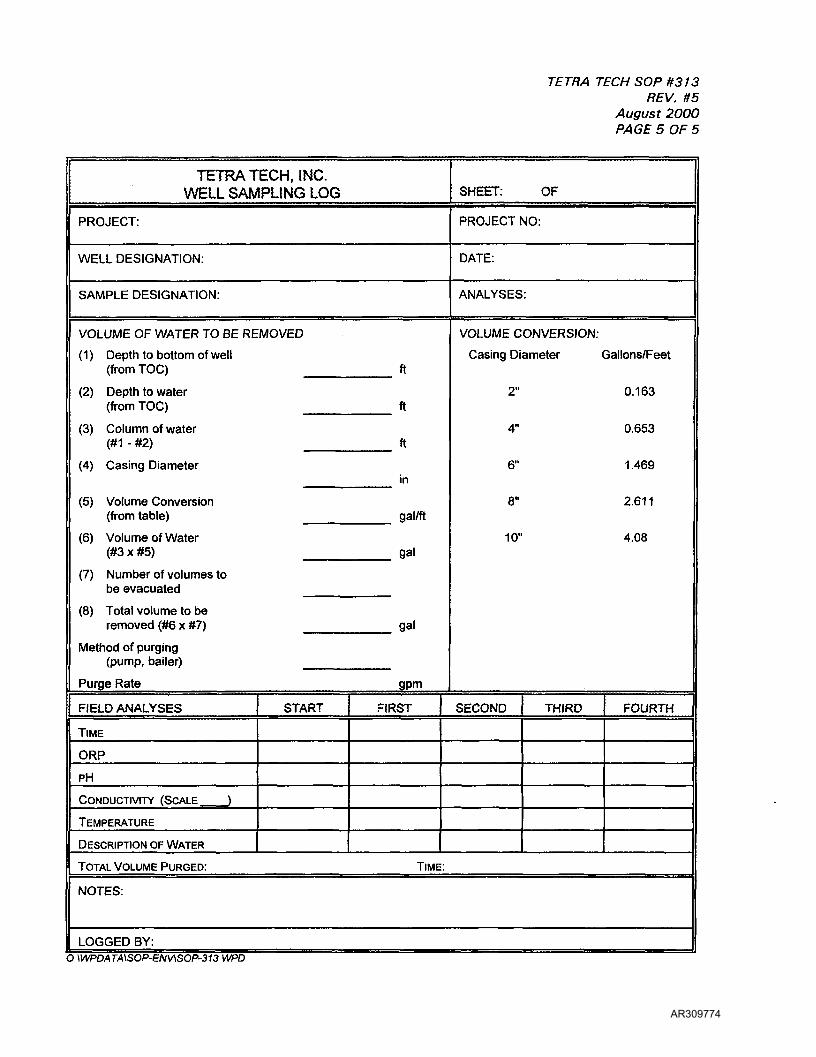
TETRA TECH SOP #313REV. #5
August 2000PAGE 5 OF 5
TETRA TECH, INC.WELL SAMPLING LOG
PROJECT:
WELL DESIGNATION:
SAMPLE DESIGNATION:
VOLUME OF WATER TO BE REMOVED
(1 ) Depth to bottom of well(from TOG) ft
(2) Depth to water(from TOG) ft
(3) Column of water(#1 - #2) ft
(4) Casing Diameterin
(5) Volume Conversion(from table) gal/ft
(6) Volume of Water(#3 x #5) gal
(7) Number of volumes tobe evacuated
(8) Total volume to beremoved (#6 x #7) gal
Method of purging(pump, bailer)
Purge Rate gpm
FIELD ANALYSES START FIRST
TIME
ORP
PH
CONDUCTIVITY (SCALE )
TEMPERATURE
DESCRIPTION OF WATER
SHEET: OF
PROJECT NO:
DATE:
ANALYSES:
VOLUME CONVERSION:
Casing Diameter Gallons/Feet
2" 0.163
4" 0.653
6" 1.469
8" 2.611
10" 4.08
SECOND THIRD FOURTH
TOTAL VOLUME PURGED: TIME:
NOTES:
LOGGED BY:O \WPDATA\SOP-ENV\SOP-313 WPD
AR309774
TETRA TECH SOP #314REV. #0
September, 1997PAGE 1 OF 4
LOW FLOW GROUND-WATER PURGING AND SAMPLING
A. PURPOSE/SCOPE:
To obtain representative ground-water samples from an aquifer using Low-Flow purgingand sampling methods.
B. EQUIPMENT/MATERIALS:
Low-flow adjustable-rate submersible pump(s) of appropriate size (e.g., 2-inch GrundfosRediflow pump and controller), generator, teflon-lined tubing, polyethylene sheeting, 5-gallon bucket, meters for water level and water quality measurements, sample bottlesand preservatives, filtration system with 0.45 um filters, pH paper, sample paperwork,copies of related SOPs (#101, 200 series, #402-406, #501, 507, and all relevant 600series), sampling gloves and other PPE, logbook.
C. PROCEDURE:
1. Refer to the site Health and Safety Plan (HSP) before proceeding with any work.Describe all work in the Field Logbook (SOP#101).
2. The wells will be sampled from the least contaminated well to the mostcontaminated well.
3. Prior to sampling, all wells shall be measured for the presence of organic vapors perthe site HSP. A Flame ionization detector (SOP#201) or a Photoionization Detector(PID; SOP#203 or 205) may be used. Any readings shall be noted in the fieldlogbook, and activities shall proceed in accordance with the site HSP.
4. Using a decontaminated measurement probe, determine the depth to water in thewell (SOP#315). Do not measure the bottom well depth in order to avoid disturbingbottom sediment; use well depth information from a drillers log or other source.Calculate the fluid volume in the well casing using the multiplier shown on the WellSampling Log (attached) which corresponds to the well casing diameter.
5. Lay out polyethylene sheeting around the wellhead, and place all samplingequipment on the sheeting.
6. Attach new teflon-lined tubing to a decontaminated low-flow submersible pumpand lower the pump into the well. Equipment should be lowered into the wellslowly and carefully so as to minimize aeration of the water column, and the pumpshould be lowered only to the middle of the well screen (avoid agitation ofsediments in the bottom of the well). If the well is an unscreened rock well, lowerthe pump until it is adjacent to water-bearing fractures or other zones. Lower awater-level measurement probe into the well.
AR309775

I
TETRA TECH SOP #314REV. #0
September, 1997PAGE 2 OF 4 *'
V!
7. Begin purging water from the well at a low rate (0.2 - 0.5 liters/minute) until field 5
measurements of selected parameters have reached stability (as discussed below),indicating that representative aquifer water is being pumped. ;
i.
Calibrate field equipment per SOP#207 and/or #209. Measure conductivity(SOP#404), pH (SOP#403), temperature (SOP#402) and oxidation/reduction Ipotential (ORP; SOP#406) continuously using flow-through meters such as an in- ^line water quality system (SOP#207). The priority for stability is conductivity, pH,temperature and ORP, with any changes in water color, turbidity, or odor also ?being noted. Stability is considered to be attained when values are +/- 10% in *.three consecutive readings. If stability is not achieved, a volume of waterequivalent to three well volumes shall be purged from the well. P
8. If the water level in the well is lowered during purging, reduce the pumping rate(and note it in the logbook) to minimize drawdown. The objective is to maintain thestanding column of water above the sampling point, and to sample water inflowingfrom the formation, not to drawdown the stagnant water in the well column.Ensure that at least 1 foot of water column is present above the pump intake at iall times. If recharge is so low that drawdown is unavoidable and/or the well is |pumped dry, wait a minimum of 4 hours before attempting to collect the watersample. .
9. Fill all appropriate sample bottles directly from the low-flow pump (refer toSOP#605 for sample volumes needed, appropriate sample bottles, etc.). The first .sample collected should be the sample portion that is to be analyzed for volatile Iorganic compounds, making absolutely certain that there are no bubbles adheringto the walls or the top of the sample container. Next collect the sample portionsfor the other organic analyses, if any. Then collect the sample for the inorganic Iparameter of cyanide. Finally, collect a sample for metals analysis. If a dissolvedmetals analysis is requested, that portion of the sample will be filtered in the fieldusing 0.45-um acrylic copolymer filters in a prepackaged, disposable polypropylene Jin-line filter holder (Sample Pro assembly; Q.E.D. Environmental Systems, Inc.). The 'Grundfos pump (or other low-flow submersible pump) will be used to pump theground-water through the in-line filter and into the sample container. To reduce the Ipotential for redox reactions because of aeration, a very slow flow rate must be 'maintained (theoretically not to exceed 100 mL/minute).
!10. Ground water samples should then be preserved using the appropriate preservative «
(refer to SOP#607 for specific procedures). The samples for volatile organiccompounds should be preserved with hydrochloric acid (HCI) to a pH of less than !2. The sample to be analyzed for cyanide should be preserved with several pellets iof sodium hydroxide to a pH greater than 12. The samples to be analyzed formetals (both total and dissolved) should be preserved with nitric acid to a pH of (less than 2; DO NOT ADD PRESERVATIVES PRIOR TO FILTRATION OF METALS !SAMPLES!
AR309776

TETRA TECH SOP #314REV. no
September, 1997PAGE 3 OF 4
11. After all sample containers are filled, recheck that the sample collected for theanalysis of volatile organic compounds does not contain headspace or bubbles. Ifany air bubbles are present, the VGA sample must be recollected using a freshsample container. All samples collected will be filled to the capacity required foranalysis per SOP# 605.
1 2. Complete all sample labels and place the samples into a cooler with blue-ice orsimilar ice packs; maintain a sample temperature Of 4 degrees C. Complete allrelevant sample paperwork (tags, Chain-of-Custody form) per SOP#611-619depending upon the required analyses.
13. Decontaminate all equipment (probes, pump, electrical cords, etc.) used duringpurging and sampling per SOP#501 and 507.
14. Once all samples have been collected, pack samples per SOP#621 for shipment tothe laboratory for analysis.
D. QA/QC REQUIREMENTS:
Refer to SOP#609 for a discussion of required QA/QC samples and sampling procedures.Field check sample pH following preservation per SOP#608.
E. SPECIAL CONDITIONS:
This method is recommended for the sampling of small-diameter wells with shortscreened intervals. It is not optimal for the sampling of large-diameter or deep-screenedwells due to the limitations of the Low-flow pump; traditional methods (e.g., SOP#313)are recommended for those conditions.
E. REFERENCES:
Contract Laboratory Program Sampler's Guide (1996); EPA Quality Assurance Directive023 (8/94); Air Force Center for Environmental Excellence (AFCEE) Handbook for theInstallation Restoration Program (9/93).
AR309777
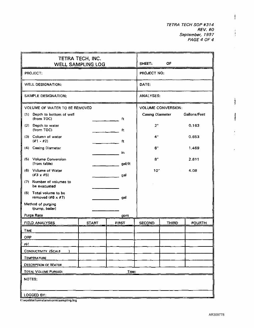
TETRA TECH SOP #314REV. #0
September, 1997PAGE 4 OF 4
TETRA TECH, INC.WELL SAMPLING LOG
PROJECT:
WELL DESIGNATION:
SAMPLE DESIGNATION:
VOLUME OF WATER TO BE REMOVED
(1) Depth to bottom of well(from TOC) ft
(2) Depth to water(from TOC) ft
(3) Column of water(#1 - #2) ft
(4) Casing Diameterin
(5) Volume Conversion(from table) gal/ft
(6) Volume of Water(#3 x #5) gal
(7) Number of volumes tobe evacuated
(8) Total volume to beremoved (#6 x #7) gal
Method of purging(pump, bailer)
Purge Rate gpm
FIELD ANALYSES START FIRST
TIME
ORP
PH
CONDUCTIVITY (SCALE )
TEMPERATURE
DESCRIPTION OF WATER
SHEET: OF
PROJECT NO:
DATE:
ANALYSES:
VOLUME CONVERSION:
Casing Diameter Gallons/Feet
2" 0.163
4" 0.653
6" 1.469
8" 2.611
10" 4.08
SECOND THIRD FOURTH
TOTAL VOLUME PURGED: TIME:
NOTES:
LOGGED BY:f:\wpdata\forrns\environm\sannpling.log
AR309778
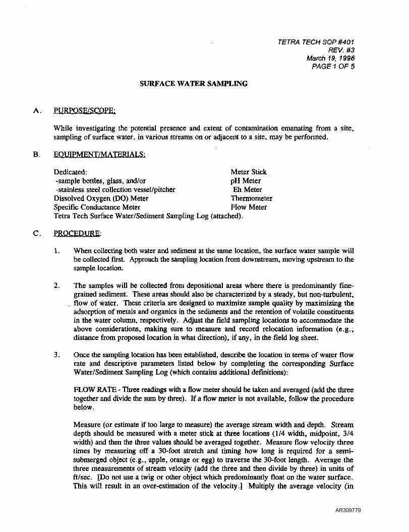
TETRA TECH SOP #401REV. #3
March 19, 1996PAGE 1 OF 5
SURFACE WATER SAMPLING
A. PURPOSE/SCOPE:
While investigating the potential presence and extent of contamination emanating from a site,sampling of surface water, in various streams on or adjacent to a site, may be performed.
B. EQUIPMENT/MATERIALS:
Dedicated: Meter Stick-sample bottles, glass, and/or pH Meter-stainless steel collection vessel/pitcher Eh Meter
Dissolved Oxygen (DO) Meter ThermometerSpecific Conductance Meter Flow MeterTetra Tech Surface Water/Sediment Sampling Log (attached).
C. PROCEDURE:
1. When collecting both water and sediment at the same location, the surface water sample willbe collected first. Approach the sampling location from downstream, moving upstream to thesample location.
2. The samples will be collected from depositional areas where there is predominantly fine-grained sediment. These areas should also be characterized by a steady, but non-turbulent,flow of water. These criteria are designed to maximize sample quality by maximizing theadsorption of metals and organics in the sediments and the retention of volatile constituentsin the water column, respectively. Adjust the field sampling locations to accommodate theabove considerations, making sure to measure and record relocation information (e.g.,distance from proposed location in what direction), if any, in the field log sheet.
3. Once the sampling location has been established, describe the location in terms of water flowrate and descriptive parameters listed below by completing the corresponding SurfaceWater/Sediment Sampling Log (which contains additional definitions):
FLOW RATE - Three readings with a flow meter should be taken and averaged (add the threetogether and divide the sum by three). If a flow meter is not available, follow the procedurebelow.
Measure (or estimate if too large to measure) the average stream width and depth. Streamdepth should be measured with a meter stick at three locations (1/4 width, midpoint, 3/4width) and then the three values should be averaged together. Measure flow velocity threetimes by measuring off a 30-foot stretch and timing how long is required for a semi-submerged object (e.g., apple, orange or egg) to traverse the 30-foot length. Average thethree measurements of stream velocity (add the three and then divide by three) in units offt/sec. [Do not use a twig or other object which predominantly float on the water surface.This will result in an over-estimation of the velocity.] Multiply the average velocity (in
AR309779
TETRA TECH SOP #401REV. #3
March 19, 1996PAGE 2 OF 5
feet/sec) by the average stream width (in feet), then multiply by the stream average depth (infeet). The product will be the average flow volume in units of cubic feet/sec.
DESCRIPTIVE PARAMETERS - Describe the surface water/sediment sampling location bydescribing the stream bed, the stream water, and surrounding environment. Refer to thesampling log and complete it as follows: Describe the amount of organic material seen in thestream, from toppled trees and branches to fine particles on the bed. Estimate the texture ofthe stream sediment (% rocks, gravel, sand, silt/clay, etc.) and estimate the depth of sedimentsample collection. Describe the water in terms of turbidity (clear, slightly turbid, moderatelyturbid, very turbid), and odor, if any. Describe the stream at the sampling location in termsof the percentage of pool (deep, calm, pooled areas), % riffle (shallow, swift-flowing, withthe surface broken e.g., tumbling over rocks), and % run (smoothly flowing). The sum ofthe three types should total 100%. Describe the adjacent banks and surrounding area in termsof amount and type of vegetation, steepness of the banks, rocky versus muddy banks,outcrops, sunny vs. shady, etc.
4. One team member will perform the actual sample collection; he/she will carefully adopt anoptimal sampling position, and once in that position, will not move his/her feet until allsampling at that locality is concluded in order to minimize agitation of the sediment and water.
5. Stream sediments are to remain undisturbed by the water collection vessel. Should contactwith the bottom and resuspension of sediment occur, the sampling team is to halt samplinguntil the water has cleared. If the water does not clear within a few minutes, the team is toproceed slightly upstream (about 1 meter or just above the disturbed area) and resume thesampling effort.
6. Submerge the open water collection vessel in water with mouth below the water surface.Take care not to collect any floating solids or materials disturbed from the bottom of the waterbody. In areas of active flow, point bottle mouth downstream. (A stainless steel pitcher maybe used to facilitate collection of the portion of the sample for analysis of organics, but shouldnot be used to collect the portion to be analyzed for inorganics).
7. Using the collection vessel, transfer the necessary amount of surface water from the waterbody to a container for field measurements of Eh, pH, specific conductance, dissolvedoxygen, and temperature. The size and type of container to be used, and the amount of waterneeded, will vary depending upon the instruments used to measure the field parameters; someinstruments are equipped with specially designed cups to hold the water, submersibleinstruments (e.g., the YSI meter) are placed into the actual water body itself, etc. Proceduresfor each field measurement are specified in Tetra Tech SOP's #402 through 406. Record thefield parameter measurements on the log sheet.
8. Use the collection vessel to fill all designated sample bottles. Collect the volatile organicfraction first, if it is to be collected. Add appropriate preservatives to samples as given inSOP #607.
9. Label the sample bottles with all necessary information.
AR309780

TETRA TECH SOP #401REV. #3
March 19, 1996PAGE 3 OF 5
10. Place the properly labeled sample bottles in a cooler with ice and maintain at 4°C for theduration of the sampling and transportation period. Do not allow samples to freeze.
11. Record all sampling information in the field logbook and complete all chain-of-custodydocuments.
12. Photograph the sampling location for future reference, being sure to photograph any notablefeatures present at the sampling location.
D. OA/QC REQUIREMENTS:
None.
E. SPECIAL CONDITIONS
Make special efforts to limit disturbance of the water body prior to sampling. If biological samplingis to be performed, complete the chemical sampling and field measurements first.
F. REFERENCES:
None.
AR309781

TETRA TECH SOP #401REV. #3
March 19, 1996PAGE 4 OF 5
TFTKA TECH, INC.SURFACE WATEK/SEDIMENT SAMPLING LOG Pagel of 2 Log No.:
Project: Project No.:
Date:
Sample Designation: Start Time:Finish Time:
Sample Location: Analyses:
FLOW RATE
(1) Stream Width
(2a) Stream Depth
(2b) Stream Depth
(2c) Stream Depth
(3a) Flow Velocity
(3b) Flow Velocity
(3c) Flow Velocity
_ft
_ft
_ft
_ft
_ ft/sec
_ft/sec
ft/sec
(4) Average Stream Depth
(2a + 2b + 2c) + 3
(5) Average Flow Velocity
(3a + 3b + 3c) + 3
(6) Average Flow Volume
(1x4x5)
(7) High Water Mark
ft/sec
eft/sec
ft
DESCRIPTIVE PARAMETERS
% Organic Substrate:
% of Organic Substrate that is:
% Inorganic Substrate:
% of Inorganic Substrate that is:
Color of Sediment:
Sample Collection Depth (sediment):
Water Turbidity (C. ST. MT, VT):
% Riffle/Run/Pool:
Odor (1.2. 3,4,5):
Detritus. Muck/Mud % Marl
Bedrock % Boulder . _% Cobble. _% Gravel % Sand % Silt Clay.
Riffle. Run % Pool
DESCRIPTION OF ADJACENT AREA (SUBMERGED VEGETATION, BANK VEGETATION/COVER, WIDTH OF FLOOD ZONE. CHANNELIZATION, RUN/BEND RATIO, % SHADE COVER, %SNAGS. ETC.):
AR309782

TETRA TECH SOP #401REV. #3
March 19, 1996PAGE 5 OF 5
WATER QUALITY PARAMETERS Page 2 or 2PRIMARY PARAMETERS
Parameter
Oxidation-Reduction Potential
pHSpecific Conductivity
Temperature
Dissolved Oxygen
Result Units
Log No.:
SUPPLEMENTAL PARAMETERSParameter
Acidity
Residual Chloride
Salinity
Other:
Other:
Result Units
NOTES:
Logged By: Photograph #:
DATA FORM KEY
ORGANIC SUBSTRATEdetritus - Disintegrated or partially disintegrated coarse organic matter (e.g.,
leaves, twigs, bark)
INORGANIC SUBSTRATEbedrock - solid rock surfaceboulder - diameter > 10 inchescobble - diameter 2.5 to 10 inchesgravel - diameter 0. 1 to 2.5 inches
TURBIDITY OF WATERC - clearST - dull clarity, visibility through water 5+ ft
ODOR0 - no odor1 - trace, intermittent odor near water surface2 - moderate odor intermittent near water surface, or weak odor
continually in breathing zone
muck/mud - fine, rich, loose, organic soilmarl - lime-like material such as shells or
limestone
sand - gritty, course inorganic materialsilt - fine, smooth, inorganic materialclay - slick, plastic, ultra-fine inorganic material
MT - clouded, visibility through water 2 to 5 ftVT - highly turbulent, visibility through water <2 ft
3 - moderate odor continually near water surface4 - moderate to strong odor near water surface and
moderate odor in breathing zone5 - powerful odor throughout sample location
DESCRIPTION OF STREAM AND ADJACENT AREAsnag: any log, clump, or twig within and submerged in the water body,
riparian: pertaining to the bank or shore of a water body,
high water mark: the highest point within the riparian area where there is evidence of water flow associated with flooding.
bend/run ratio: the ratio of additional stream flow distance resultant from the bends as compared to the straight linear distance a segment ofa stream (run) travels,
channelization: the extent of which the stream has developed a defined pathway through the existing terrain.
f:\wpdata\sop-env\sop-401. wp
AR309783
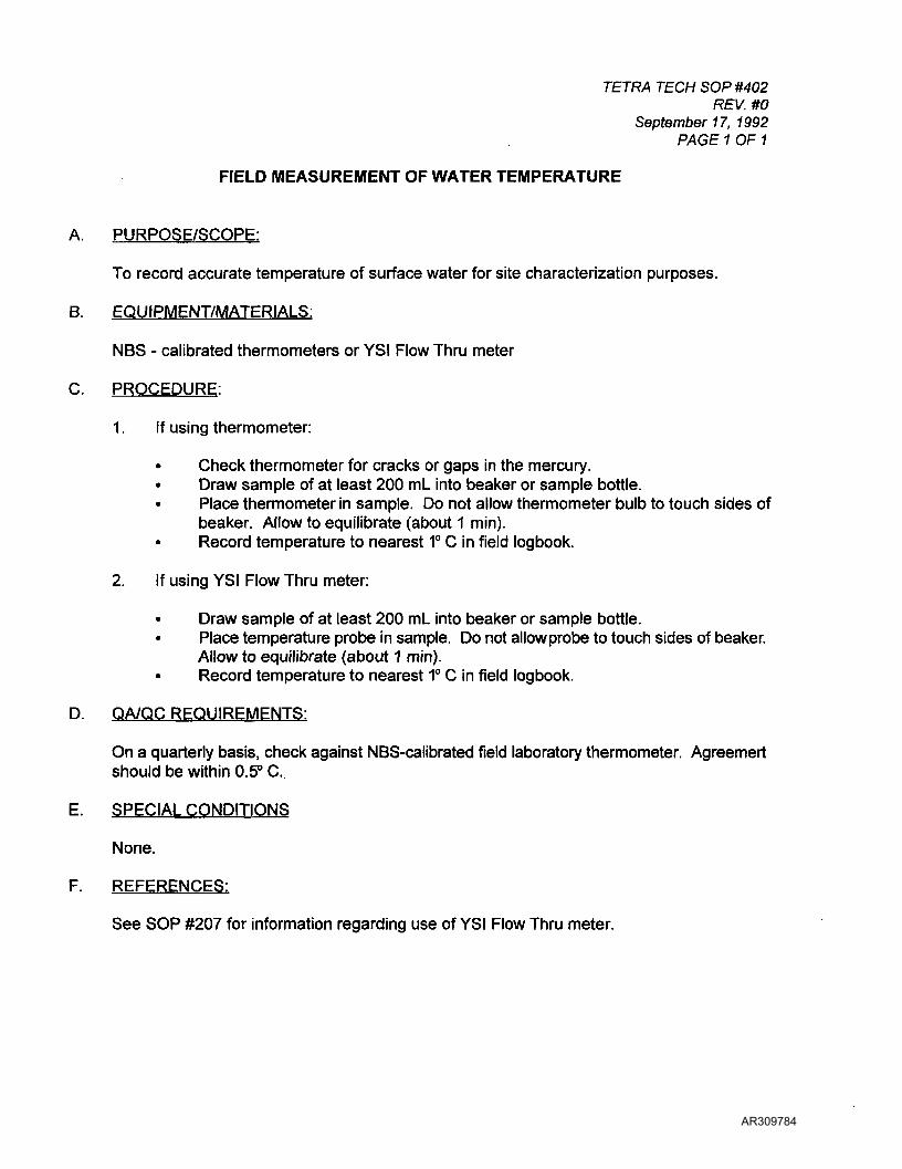
TETRA TECH SOP #402REV. #0
September 17, 1992PAGE 1 OF 1
FIELD MEASUREMENT OF WATER TEMPERATURE
A. PURPOSE/SCOPE:
To record accurate temperature of surface water for site characterization purposes.
B. EQUIPMENT/MATERIALS:
NBS - calibrated thermometers or YSI Flow Thru meter
C. PROCEDURE:
1. If using thermometer:
• Check thermometer for cracks or gaps in the mercury.• Draw sample of at least 200 mL into beaker or sample bottle.• Place thermometer in sample. Do not allow thermometer bulb to touch sides of
beaker. Allow to equilibrate (about 1 min).Record temperature to nearest 1° C in field logbook.
2. If using YSI Flow Thru meter:
• Draw sample of at least 200 mL into beaker or sample bottle.• Place temperature probe in sample. Do not allow pro be to touch sides of beaker.
Allow to equilibrate (about 1 min).• Record temperature to nearest 1° C in field logbook.
D. QA/QC REQUIREMENTS:
On a quarterly basis, check against NBS-calibrated field laboratory thermometer. Agreemertshould be within 0.5° C.
E. SPECIAL CONDITIONS
None.
F. REFERENCES:
See SOP #207 for information regarding use of YSI Flow Thru meter.
AR309784
TETRA TECH SOP #403REV. #0
September 17, 1992PAGE 1 OF 1
FIELD MEASUREMENT OF pH FOR SURFACE AND GROUND WATERS
A. PURPOSE/SCOPE:
To accurately record the pH of water for site characterization purposes.
B. EQUIPMENT/MATERIALS:
Markson 611 pH meter or YSI Flow Thru meter, spare battery, plastic beakers, buffer solutionof pH4, 7, and 10.
C. PROCEDURE:
1. Rinse 500-mL plastic beaker with small portions of sample water 3 times.
2. Rinse electrodes with sample water.
3. Immerse electrode in sample while swirling the sample, if needed, to provide thoroughmixing. Turn on meter. Read pH to nearest 0.1 unit once the reading is stabilized.
4. Record sample pH. Note any problems such as drift of meter.
D. QA/QC REQUIREMENTS:
A calibration verification check standard will be analyzed after every ten readings.
Check batteries each time the meter is used. Carry a spare battery pack and a screwdriverinto the field in the pH meter case.
E. SPECIAL CONDITIONS
None.
F. REFERENCES:
Refer to SOP's # 207 and 209 for further information.
AR309785
TETRA TECH SOP #404REV. #1
April 2000PAGE 1 OF 1
FIELD MEASUREMENT OF SPECIFIC CONDUCTANCE
A. PURPOSE/SCOPE:
To accurately record the specific conductance of water for site characterization purposes.
B. EQUIPMENT/MATERIALS:
YSI Flow Thru Meter, plastic or glass beaker
C. PROCEDURE:
1. Mechanically zero the instrument while the instrument is OFF using screwdriveradjustment on the meter face.
2. Collect water sample in 500-mL plastic beaker.
3. Swirl conductivity probe in sample; discard sample.
4. Collect fresh sample in beaker.
5. Measure sample temperature to nearest 1° C.
6. Adjust the temperature setting on conductivity meter as per recorded temperature.
7. Turn on meter and immerse conductivity probe in sample. Move probe around insample to displace any air bubbles.
8. Select the lowest appropriate multiplier setting to obtain the greatest meter needledeflection. Read the conductivity from the dial and record in field notebook.
D. QA/QC REQUIREMENTS:
A calibration verification check standard will be analyzed at the beginning and end of eachwork-day.
E. SPECIAL CONDITIONS
None.
F. REFERENCES:
See SOP #207 for further information.
AR309786
TETRA TECH SOP #406REV. #0
September 22, 1992PAGE 1 OF 1
FIELD MEASUREMENT OF REDOX POTENTIAL (Eh)
A. PURPOSE/SCOPE:
To accurately record the Eh of water for site characterization purposes.
B. EQUIPMENT/MATERIALS:
YSI Flow Thru meter, spare battery, plastic beakers,
C. PROCEDURE:
1. Rinse 500-mL plastic beaker with small portions of sample water 3 times.
2. Rinse electrode with sample water.
3. Immerse electrode in sample while swirling the sample, if needed, to provide thoroughmixing. Turn on meter. Read Eh to nearest 1 millivolt once the reading is stabilized.
4. Record sample Eh in the field log book. Note any problems such as drift of meter.
D. QA/QC REQUIREMENTS:
None.
E. SPECIAL CONDITIONS
None.
F. REFERENCES:
Refer to SOP #207 for further information.
AR309787
TETRA TECH SOP #407REV. #4
August 2000PAGE 1 OF 1
SURFACE SOIL SAMPLING
A. PURPOSE/SCOPE:
To characterize surface soil.
B. EQUIPMENT/MATERIALS:
The equipment needed for this task includes a hand auger, a shovel, stainless-steel or plasticscoops, stainless-steel or glass bowls, wooden stakes, a hammer, indelible ink pens, a 300-foot measuring tape, and the appropriate sample jars.
C. PROCEDURE:
1. Use the shovel to clear any surface debris from the sampling location, including grassesor other vegetation.
2. Unless specified differently in the FSP (see FSP requirements), collect the samplesfrom 0-6 inches with a scoop. Stainless steel should be used to collect organic portionand plastic should be used to collect inorganic portion. Carefully push the soil out of thescoop into a stainless-steel or glass bowl.
3. If volatile organic compounds analysis is required, pack the volatile organic compoundssample jars first. Then pack all other sample fractions. The samples should bepreserved by cooling to 4°C.
4. After sampling is completed, the sampling location should be marked by a woodenstake. The station number and date of sampling should be written on the stake inindelible ink. Then use the measuring tape to the distance and direction to the nearestlandmark. Record the location in the field logbook.
5. Decontaminate the sampling equipment as specified in SOP #501 and move to the nextsampling location. Repeat steps 1 through 4.
D. QA/QC REQUIREMENTS:
None.
E. SPECIAL CONDITIONS
Surface soil sampling that will provide data for human health risk assessment purposesshould consider potential exposure scenarios as part of sample collection design. Unlessspecified differently in the FSP (see FSP requirements), samples to provide data forevaluation of soil ingestion should be collected from a depth of 0 to 1 inches (0 to 2 cm), andshould consist of a composite of 4 individual samples as described in the FSP. Compositesampling should be performed in accordance with SOP #409.
This approach is not applicable for volatile organic compounds, as volatiles are not expectedto remain in surface soil for an extended period of time.
F. REFERENCES:
1996 EPA Soil Screening Guidance: Users Guide (Publication 9355.4-23, July 1996).
AR309788
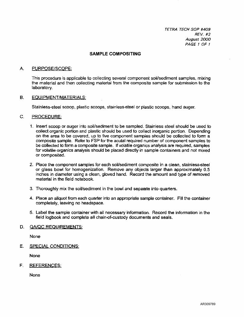
TETRA TECH SOP #409REV. #2
August 2000PAGE 1 OF 1
SAMPLE COMPOSITING
A. PURPOSE/SCOPE:
This procedure is applicable to collecting several component soil/sediment samples, mixingthe material and then collecting material from the composite sample for submission to thelaboratory.
B. EQUIPMENT/MATERIALS:
Stainless-steel scoop, plastic scoops, stainless-steel or plastic scoops, hand auger.
C. PROCEDURE:
1. Insert scoop or auger into soil/sediment to be sampled. Stainless steel should be used tocollect organic portion and plastic should be used to collect inorganic portion. Dependingon the area to be covered, up to five component samples should be collected to form acomposite sample. Refer to FSP for the acutal required number of component samples tobe collected to form a composite sample. If volatile organics analysis are required, samplesfor volatile organics analysis should be placed directly in sample containers and not mixedor composited.
2. Place the component samples for each soil/sediment composite in a clean, stainless-steelor glass bowl for homogenization. Remove any objects larger than approximately 0.5inches in diameter using a clean, gloved hand. Record the amount and type of removedmaterial in the field notebook.
3. Thoroughly mix the soil/sediment in the bowl and separate into quarters.
4. Place an aliquot from each quarter into an appropriate sample container. Fill the containercompletely, leaving no headspace.
5. Label the sample container with all necessary information. Record the information in thefield logbook and complete all chain-of-custody documents and seals.
D. QA/QC REQUIREMENTS:
None
E. SPECIAL CONDITIONS:
None
F. REFERENCES:
None
AR309789
TETRA TECH SOP #415REV. #0
July 11, 1996PAGE 1 OF 1
METHANOL PRESERVATION VOLATILE METHOD
A. PURPOSE/SCOPE:
The objective of this task is to properly preserve solid samples proposed for volatile organiccompound (VOC) analysis for State of Delaware Department of Natural Resources andEnvironmental Control (DNREC) Hazardous Substance Cleanup Act (HSCA) projects.
B. EQUIPMENT/MATERIALS:
Laboratory provided containers and methanol/surrogate
C. PROCEDURE (from DNREC SOCAP):
1. The laboratory is responsible for assembling the methanol preservation sampling kits.Each sample shall be packed in a steel container using vermiculite as a packingmaterial. The containers are sealed and packed into coolers for shipment. Eachsample kit should be prepared no earlier than one week prior to sampling.
2. Upon receipt of the laboratory containers and prior to sampling, each container shallbe checked for leakage and the appropriate volume of methanol/surrogate(approximately 250 ml). Sample containers which are found to be leaking or do notcontain sufficient methanol/surrogate liquid shall not be used for sampling. Thelaboratory shall be notified of sample container problems.
3. Approximately 250 grams of the soil/sediment sample should be taken and placed intothe methanol within the sampling bottle with a minimum of disturbance. Do not mix,homogenize, or stir the sample prior to or after placing it in the bottle. Work quicklyand do not disturb the sample more than necessary when transferring it to the samplecontainer.
4. After the soil/sediment has been placed in the sample bottle, carefully wipe allsoil/sediment from the lip of the sample bottle and cap it tightly. Pack samples on iceand transport at 4°C. The samples should also be stored at 4°C.
D. QA/QC REQUIREMENTS:
None.
E. SPECIAL CONDITIONS
The methanol surrogate is a strong oxider and Class IB flammable liquid that requires specialhandling considerations.
F. REFERENCES:
Delaware Department of Natural Resources and Environmental Control (DNREC) SiteInvestigation and Restoration Branch, Standard Operating Procedures for Chemical AnalyticalPrograms under the Hazardous Substance Cleanup Act, December 1992, revised July 1994and May 1995.
AR309790
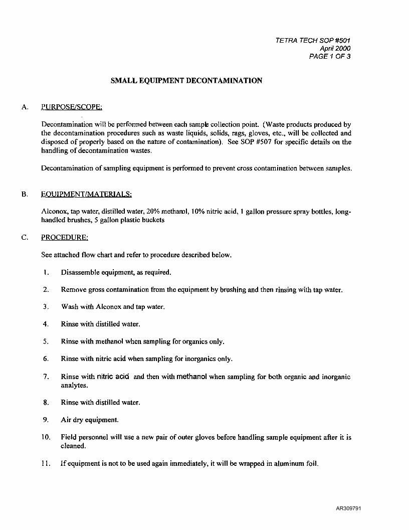
TETRA TECH SOP #501April 2000
PAGE 1 OF 3
SMALL EQUIPMENT DECONTAMINATION
A. PURPOSE/SCOPE:
Decontamination will be performed between each sampfe collection point. (Waste products produced bythe decontamination procedures such as waste liquids, solids, rags, gloves, etc., will be collected anddisposed of properly based on the nature of contamination). See SOP #507 for specific details on thehandling of decontamination wastes.
Decontamination of sampling equipment is performed to prevent cross contamination between samples.
B. EQUIPMENT/MATERIALS:
Alconox, tap water, distilled water, 20% methanol, 10% nitric acid, 1 gallon pressure spray bottles, long-handled brushes, 5 gallon plastic buckets
C. PROCEDURE:
See attached flow chart and refer to procedure described below.
1. Disassemble equipment, as required.
2. Remove gross contamination from the equipment by brushing and then rinsing with tap water.
3. Wash with Alconox and tap water.
4. Rinse with distilled water.
5. Rinse with methanol when sampling for organics only.
6. Rinse with nitric acid when sampling for inorganics only.
7. Rinse with nitric acid and then with methanol when sampling for both organic and inorganicanalytes.
8. Rinse with distilled water.
9. Air dry equipment.
10. Field personnel will use a new pair of outer gloves before handling sample equipment after it iscleaned.
11. If equipment is not to be used again immediately, it will be wrapped in aluminum foil.
AR309791
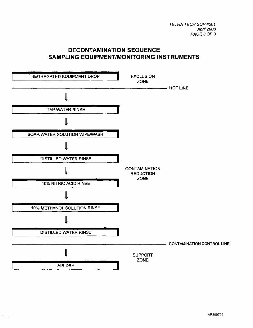
TETRA TECH SOP #501April 2000
PAGE 3 OF 3
DECONTAMINATION SEQUENCESAMPLING EQUIPMENT/MONITORING INSTRUMENTS
SEGREGATED EQUIPMENT DROP EXCLUSIONZONE
HOT LINE
IITAP WATER RINSE
SOAP/WATER SOLUTION WIPE/WASH |
II
I
AIR DRY
CONTAMINATIONREDUCTION
ZONE
CONTAMINATION CONTROL LINE
SUPPORTZONE
AR309792

TETRA TECH SOP #503REV. #0
September 18, 1992PAGE 1 OF 1
LARGE EQUIPMENT DECONTAMINATION
A. PURPOSE/SCOPE:
Decontamination of large equipment (drilling rigs, backhoe excavators, bulldozers, etc., isnecessary to prevent cross-contamination between sampling points and to prevent the removalof contaminants from a hazardous waste site.
B. EQUIPMENT/MATERIALS:
Steam cleaner, generator, decontamination pad, 55-gallon drums, centrifugal pump, dischargehose.
C. PROCEDURE:
1) Unless otherwise noted, all decontamination of large equipment will take place on adecontamination pad designed to collect all rinsate generated during the cleaning activity.
2) The drilling rig/excavation equipment and materials need to arrive on-site in a cleancondition, and should be free of oil, grease, and debris. Inspect the rig for any fluid leaks.
3) Steam clean the drill rig/excavator, tools, drill bits, buckets, etc., are steam cleaned priorto the start of work. After steam cleaning, the equipment should be inspected for residuessuch as machine oil. If residues are observed, the equipment should be steam cleaneduntil such residues are removed.
4) In the event that equipment is contaminated with heavy oils or products that cannot beremoved by the standard decontamination procedures outlined above, the followingmodifications will be made. First, wipe all excess oil/tar from the equipment with a papertowel or clean rag. Second, with a paper towel or clean rag that has been soaked inhexane, wipe any residual contamination off the equipment When equipment is relativelyfree of gross oil or tar contamination, proceed with the usual decontamination procedure.
5) At the completion of the project, or when required, all rinsate generated fromdecontamination activities shall be pumped from the decontamination pad to 55-gallondrums for disposal.
D. QA/QC REQUIREMENTS:
None.
E. SPECIAL CONDITIONS
None.
F. REFERENCES:
None.
AR309793
TETRA TECH SOP #505REV. #0
September 18, 1992PAGE 1 OF 4
DECONTAMINATION PROCEDURE FOR PERSONNEL
A. PURPOSE/SCOPE:
The objective of decontamination is to prevent the transmission of contaminants to personndand equipment and to prevent the spread of contaminants off-site. Decontamination isperformed as a quality assurance measure and as a safety precaution during sampling.
Decontamination of personnel and equipment shall take place in the Contamination ReductionZone.
All personnel must undergo decontamination prior to leaving the site. If non-disposableclothing is used for Level D activities, it must be removed in the Decontamination reductionZone. All personnel must wash their hands with soap and waterprior to each entry back intothe Support Zone. All personnel should also shower and wash their hair as soon as possbleafter leaving the site.
B. EQUIPMENT/MATERIALS:
Decontamination pad, brushes, polyethylene, tap water, soap, 55-gallon drum shallow washbuckets.
C. PROCEDURE:
Personnel decontamination sequences for the different levels of PPE are depicted in flowcharts.
D. QA/QC REQUIREMENTS:
None.
E. SPECIAL CONDITIONS
None.
F. REFERENCES:
OSHA Manual for Hazardous Waste Site Activities
AR309794
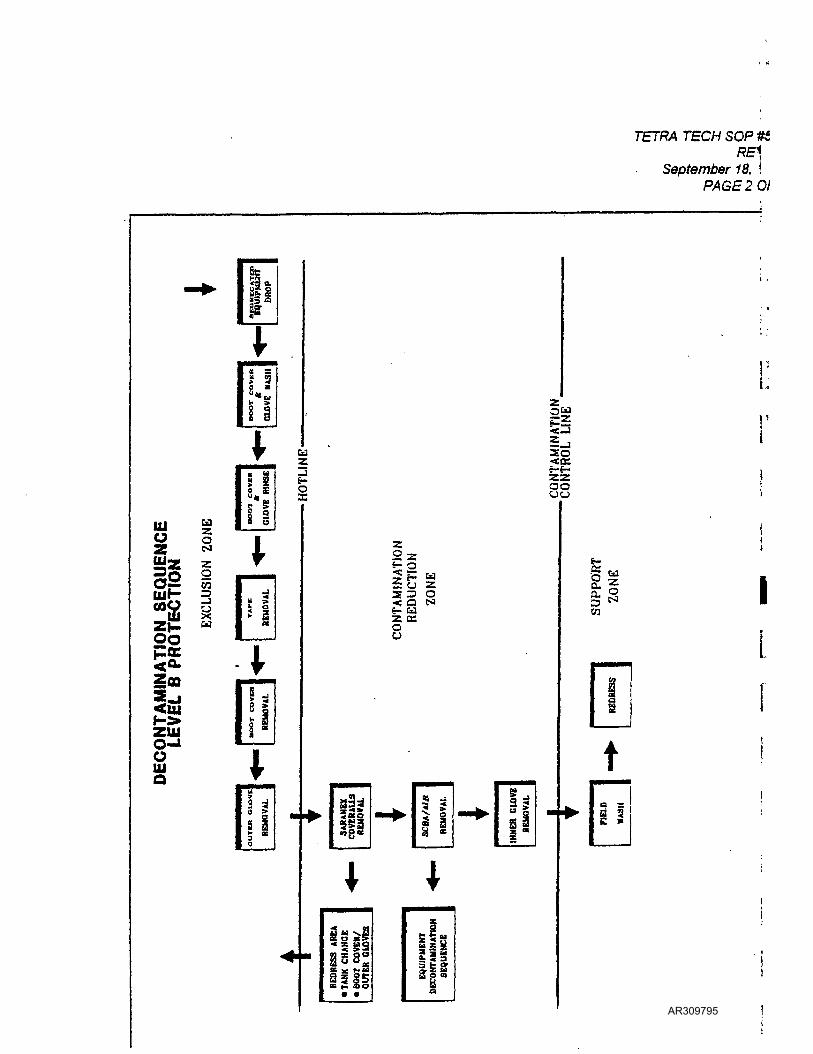
TETRA TECH SOP IK.RE1
September 18, IPAGE 2 O/
32 sII2
i a i«
SO
Ulo2
i!
§ SS
2 §COOgff00poc<a-
f->ZUJO-JoUlo
f-£ u
wS 3 O< o tJ&- CdZ KOO
I I*
il
Iw
t
II
AR309795
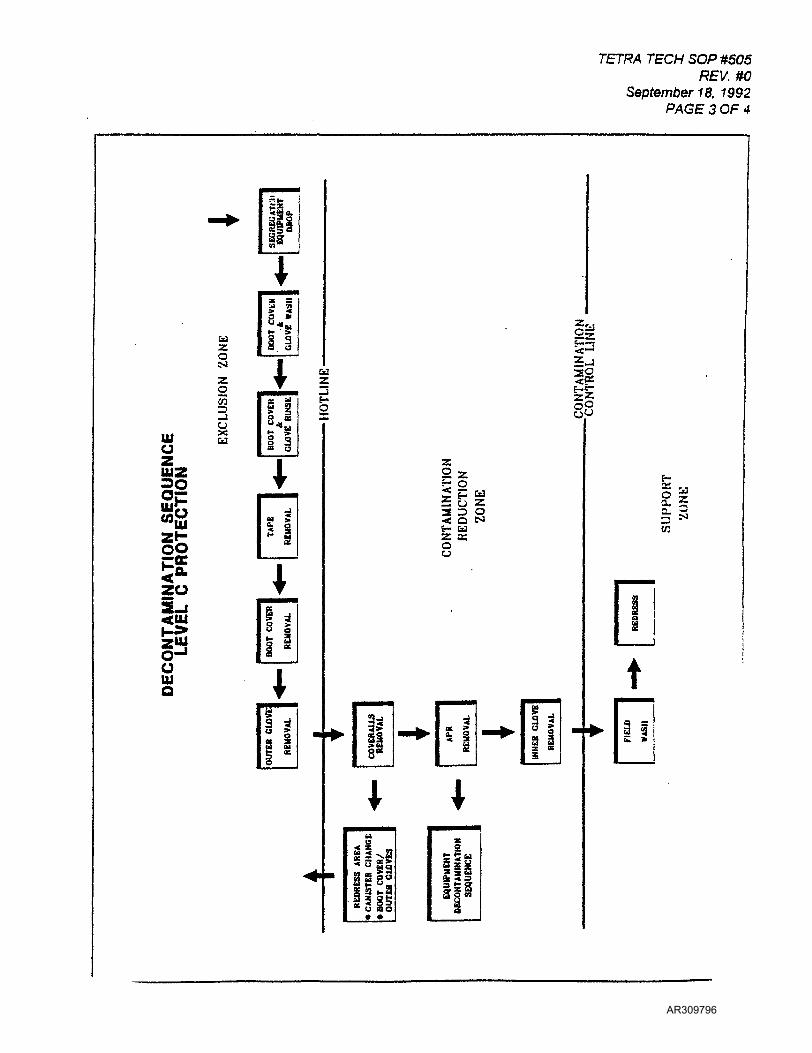
TETRA TECH SOP #505REV. #0
September 18, 1992PAGE 3 OF 4
tdZ
N
ZO55
tilO
WZ
22SP
CdZZjo
1*!!
920
ottla
li5& zs 3 q<: a ts&*• uz a:oo
IIen
1 i
AR309796
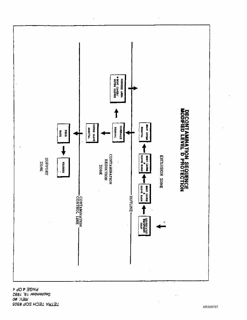
c
0 ^
"1
* 3
i i•••
. §- (A
MM^
««• •
0
» 5n ns *g 5
S•*-
illIIIPi
t» 9
< c
•
<*
n33 Zn -3
0 C S
-31i^Z 0z
onoo-i-i
or
r;>
CTjC
»>
Om0050
£ gID• ••iBi
t§-
1110 yE |
— ? Io | .a-jrip
m5
^2[25m>rnoo
P5 *B>
o 'j 3D^^J
i 2So HDz meomo HZM Om
Z
i ---•- -B
' tMCA
s-f5
J|
. ^
*• JOZ66LOlfASd909# dOS HO3J. VU13±
AR309797
SOP #60?REV. #2
October, 1999PAGE 1 OF 2
ANALYTICAL SERVICES (RAS and DAS) REQUESTS
A. PURPOSE/SCOPE:
To procure laboratory space for the analysis of samples at Contract Laboratory Program(CLP) labs for Routine Analytical Services (RAS) or non-routine analytical services.
B. EQUIPMENT/MATERIALS:
EPA Region III RAS-DAS Sample Scheduling Request Form (copy attached).
C. PROCEDURE:
1. The sampler initiates the request by completing the electronic Sample SchedulingRequest Form, and e-mailing it to the site Regional Project Manager for EPA reviewat least 6 weeks prior to the sampling event. The RPM or WAM will review therequest, and forward it to the EPA OASQA Client Services Team (CST) for technicalreview and procurement. To check on the progress of the RAS or DAS request, thecontact is Betty Ann Jeffrey (410) 305-2601.
Information to be provided on the Request form include: samplers' name, sampler'sphone number, site name, city and state where site is located, site spill identificationnumber, expected date of sampling, number of samples, type of analyses, requestedturn-around time, fractions to be analyzed, and sample matrices.
D. QA/QC:
Save a copy of the completed electronic Request into the site file. Document all telephonecommunications on a "Record of Telephone Conversation Log."
E. SPECIAL CONDITIONS:
None.
H. REFERENCES:
Sampler's Guide to the CLP (EPA/540/R-96/032); EPA Region III Users' Guide toAcquiring Analytical Services (EPA OASQA CST, June, 1999).
AR309798

Users' Guide for Acquiring Analytical ServicesRegion III Client Services Team
June 1999revision 2
Exhibit 1
U.S. EPA Region III Sample Scheduling Request Form
HAS CASE No:
Date:
Site Name
DAS No:
Data Validation Level:
Address:
Latitude:
Profram:
NSFIte:
I»AL**Ro.lT
City: State
LoMfltnde:
Account No:
Preparcr:
Phone
FAX:
E-mail:
WACO:
CEROJSNo:
Operable Unit:
RPM/PO:
Pbone:
FAX:
E-mail:
Contract Type
Lab AolfnmcBt Date:
Organic Ub:
TAT:
Anted*
AclKUy*
Spill ID:
SlteUaden
Pbooc:
PAX:
E-auil:
Prime:
Inornate Lab:
SAMPLES METHOD
Sub:
Sklppiat From:
ShlpptacTo:
Carrier.
PARAMETER MATRIX
NOTE: D«» vUMtttoa Itvcts M3 & IM1 rcqaln jwtmcallon. QC Odd auopki mwt bt Indydcd u part of total number of nmpfec.
2. ObjcctivM / Pnjtet PUo ID / Permit ID:3. Prnnm / Prefect / Permtt Reportiac Unlu4.0QO(QCR«|.lrtm«ia)
27
AR309799

TETRA TECH SOP #605REV. #6
July 2000PAGE 1 OF 4
SAMPLE PRESERVATION, HOLDING TIMES, AND CONTAINERS
A. PURPOSE/SCOPE:
To ensure sample integrity through use of proper sample preservation techniques, samplecontainers, and through observance of sample holding times.
B. EQUIPMENT/MATERIALS:
Sample containers and sample preservatives (see table).
C. PROCEDURE:
Refer to SOP #607 for preservative procedures.
D. QA/QC REQUIREMENTS:
Refer to SOP #608 for QA/QC check of sample pH to insure sufficient preservative.
E. SPECIAL CONDITIONS
None.
F. REFERENCES:
Sampler's Guide to the CLP (EPA/540/R-96/032).
AR309800
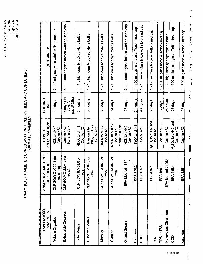
COa:UJz
OoQ
<COUJ
ozCO
ilUJ >co a;
co"onUJ
LJJ
O
o<r
ON
TAIN
E
o
o"7 -a
IsOF
01
gUJ H*
si< UJCO CO
UJ
Q.
Q0XV- UJJJJ 05 Z
ALY
TIC
AL
RE
FER
E
z
O UJ
LAB
OR
ATi
AN
ALY
S
E3"5.CDCO
1Cs!COro
inCOroCO
E~oi*i
CM
CO
ro•o•<r
CM o
^LT -i
2 " <3
s.T—S — ,O £
MCO "~a.O
Vol
atile
Org
anic
s
Q.
8•oIDc
O
1in
JB
oS3inin(0O)
<i>
ca™ 'T-
1
"*
^ ' — -CO
J3 ^co O
"O ro "co|v- ~ <U« Q.
o-£p _Jo
2 =o 20 -2
3,CM
S•5
.P S
OW
OL
revs
.
_io
.0
Ext
ract
able
Org
an
_Q)
on<Dc0)>,
ty p
olye
th
CO
CD-o
O)
.~~T—
1
"*"
CO
"c
CO
v1 OI ^j.
22**^ —
i"
o0
s5=! 5
IsCOQ.
O
inJSo>
1
JD
E0)
0)>,
f:».ai-'toCD•af™^_O)
1
^1
••"
CO£oEto
CM
*""" ^^ °.tO Q.
§ 2 2^- ^J? Oa> O ogzo
oo
s^
I1COo_
1o
Dis
solv
ed M
etal
s
jyo_o0)s>,
ty p
olye
th
CO
CD•op-^w
COJc^^T—
1
•«"
CO
roTJCOCM
CM o
•y o
2 °
l"l
t5o
s
LP S
OW
\U
revs
.
o
1CD
-CD
E(1)C
_tD>ȣ0)>^oQ.
2?inCD
CO
™*T—
t
T~
T3
fSj
JB v^Q- .y
x| 8
I8f
oos^
OCOo.o
0)
roO
Q.
8CD
0
1
toCD
1£1
£(D0)
ro™^
T—
I
CN
CO
ro
COCN
v" 0T 2-.
?2
is
sCO
•o
i1UJ
ro
O•oro
(5
CL
8TJCD
=
O
co"COroCO
oo1oCOa.
10oT—
1
•
CO.G•t-fCO
CO
CMVXo.2mO
X
CMOCO
Q.UJ
I H
ardn
ess
Q.
|"T
Q
•§
<DtJ
EtotoJO
0)
ECO
~^V
1
•
3Of~
CO
Oo
280
.,_in
EP
A 4
0
QOm
Q.80)
"T
o**=
!JD
•"COCOroCO
1inCN
iT-
CO
nT
ooCM
cro
CM O
^^ *-•
2 o68coX
T_
inT—
UJ
Oe
Q.rooTJCD
Co
CDs.uCOCOroCO
1ooini
••"
CO
ro"O
o
280
,_oCO
UJ
COCO
COQ
CUEo.aCD
JD
£Z+-»0}
"oQ-
'toCD
O)Jc~~^T-
1
••"
3O
S
o
2o00
COa>
"DO
15
E3
1 H
exav
alen
t Chr
om
Q.
S
1•-=off^
**—Q)
co"toroCO
o.0toroa.1o0T—
1
*~
CO
c^1
T3OOCN
X>
roCM O
a. o
CD cS
nf
C)
•5
UJ
ooo
Qroo•aCD
co
.£>0•COinroo
10oini
*~
CO
ro-aCOCM
O
2
80
,_in
a.UJ
II ch
lorid
es
AR309801

10 to o •*§*§^*b ^ CM O
occLU
<PZOo
OZ m
31
X
«
0LU i=
SA
MP
LP
RE
SE
RV
A
aO
LU O5 z
<K— LU
^CEZ'
DC COO uut- CO
-A8O
RA
AN
ALY
«•*«
a.8
*CV
o
15Q)
E
W(Q
"cn
110CM
-
t/jCOTJ00CM
•aCO
IIo "^•*^ o
O CJcoX*
CMCOinco
Q.LU
1
f
Q>•*-*
£C
CL
8T30)C'T0
a>
<D
-ain(0cnl_
J!(Q"^
^ —
1
W
T3OOCM
•aTO
CM OV ^
s?dc3CO
CM
CM0
Jo
a.LU
tw
'coE(Q
Q.8
1"5_^"*fl5
aico"5)u.OO
toTOCL
1
OoT—
1T-
0)
73COCM
T3
COCM 0
<D 0CO
CM
^
insLU
M
oJCCL
1CL
CL
8"8CTCOI3IDEE</)JO
10om
-
(A
•oh-
a>a> A
S Q.OS o
^? ^f
o -^- *"
•§ | 8CM ?
ca
.,_CD
CO
^LU
M(I)T31C
<n
D).C
•CV)
8*i0)
-S ^
o * J
AR309802
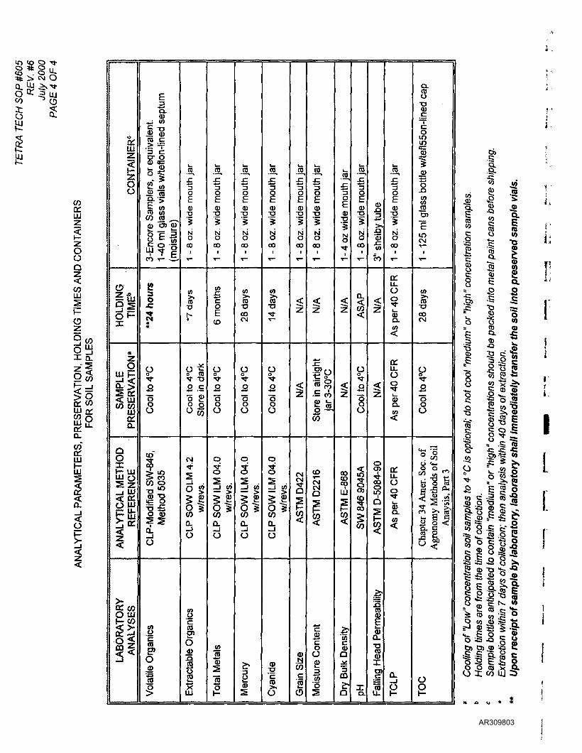
CO CD
COa:UJ
OoQ
COLU
uico
CO"o:
co
<<
oo:UJz
0o
°«
5|Sp
a
OUJ *-
SA
MP
LE
SE
RV
A
0**O.
Q
ANAL
YTIC
AL M
ETH
OR
EFER
ENC
E
>a: coQUJt- CO
|
LABO
RA
|| A
NA
LY
E3"a.CD
<j </>
§"8CO (C
'5 cCD 0=
5l"§•'>E COCO (/)
0) "5> CD
8 £ -s§
P- x-»
VJ T- —
3O
r**
0
sooO
CLP
-Mod
ified
SW
-846
Met
hod
5035
Vol
atile
Org
anic
s
jo,
5oE0)
*NO
ooi
T"
<n
TJ
*
O "^o CQ^f ^O
2 So £O oU CO
CM
0 |
COQ.
0
oc
I) E
xtra
ctab
le O
rgai
i_
^oECD•o5NOCOi
^~
(0
o
CO
p
"5oO
o
S
^^ QJ
COQ.
O
"CD
I
L.
.55,
"3gCDTI
SIMOCOi
*~
<n
COCM
O
"oo0
o
s—1 W
11COQ.
O
1CD
i"OECDT3
5
S00
1
*~
<n
•a
*~~
O
Q
I
0
3s ._l (O
11Q.
O
0)_-g
CO
O
L.
.55.
"3f£
CDTJ
SNOoo
1
^~
1
z
CM
1CO
COcEO
55.£o
CD;g5
8OOi
T™
|
"i)
(D L.
CO
CO
CMCM0
(Moi
stur
e C
onte
nt
•55,.c
0)S
8i
i
I
coCOCO
UJ
'55cuQ
CQ
a
-jo,
"3oECDT3
'i8oo
1
"""
n
i
0o
S8o
| S
W 8
46
904
5A
a.
0)•§"£,
"CDin
eo
1
Z
| A
STM
D-5
084-
90
^coa>c
CDa.
a>
O)
i_•55,
oECDT>
S
8oo
1
*~
a:U.0oL.
CDa.
<
ITu.oo
8.CO
^
u.0o
I
D.
CL
ST3CD
~romm5=
1.cu
1CO
CO0)
1mCM
1
*~
ta
•aooCM
0
"o
8
CM ~
Cha
pter
34
Am
er.
Soc
. c
Agr
onom
y M
etho
ds o
f Si
Ana
ysis
, P
art 3
g
1 •
•Q "S
illi«il!i I
L
5 CD T3 -{s -Q•S -C CD O fl)
§ C « 2.0.
Ptt|> £ i c •*-^ co w •§ osails.^ • l ^§8-^.S tl c1s ts Ic3i<5§i25-
AR309803
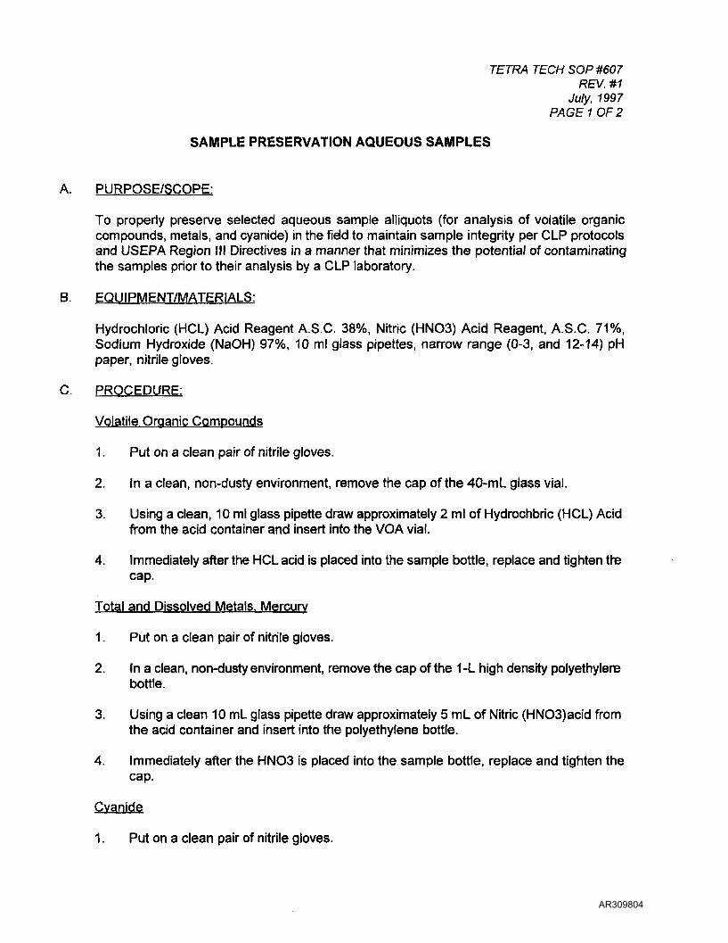
TETRA TECH SOP #607REV. #1
July, 1997PAGE 1 OF 2
SAMPLE PRESERVATION AQUEOUS SAMPLES
A. PURPOSE/SCOPE:
To properly preserve selected aqueous sample alliquots (for analysis of volatile organiccompounds, metals, and cyanide) in the field to maintain sample integrity per CLP protocolsand USEPA Region III Directives in a manner that minimizes the potential of contaminatingthe samples prior to their analysis by a CLP laboratory.
B. EQUIPMENT/MATERIALS:
Hydrochloric (HCL) Acid Reagent A.S.C. 38%, Nitric (HNO3) Acid Reagent, A.S.C. 71%,Sodium Hydroxide (NaOH) 97%, 10 ml glass pipettes, narrow range (0-3, and 12-14) pHpaper, nitrile gloves.
C. PROCEDURE:
Volatile Organic Compounds
1. Put on a clean pair of nitrile gloves.
2. In a clean, non-dusty environment, remove the cap of the 40-mL glass vial.
3. Using a clean, 10 ml glass pipette draw approximately 2 ml of Hydrochbric (HCL) Acidfrom the acid container and insert into the VOA vial.
4. Immediately after the HCL acid is placed into the sample bottle, replace and tighten thecap.
Total and Dissolved Metals. Mercury
1. Put on a clean pair of nitrile gloves.
2. In a clean, non-dusty environment, remove the cap of the 1 -L high density polyethylenebottle.
3. Using a clean 10 mL glass pipette draw approximately 5 mL of Nitric (HNOS)acid fromthe acid container and insert into the polyethylene bottle.
4. Immediately after the HNO3 is placed into the sample bottle, replace and tighten thecap.
Cyanide
1. Put on a clean pair of nitrile gloves.
AR309804

TETRA TECH SOP #607REV. #1
July, 1997 JPAGE 2 OF 2 *
2. In a clean, non-dusty environment, remove the cap of the high density polyethylene jbottle. *
3. Using your hands remove approximately 15-20 Sodium Hydroxide (NaOH) pellets from }the NaOH container and place into the sample bottle. *
4. Immediately after the NaOH is placed into the sample bottle, replace and tighten the \
E. SPECIAL CONDITIONS:
cap. 5
COD. Oil and Grease. Organic Carbon. Phenolics. Total Dissolved ?Phosphorus. Hydrolyzable Phosphorus. Ammonia. Nitrate plus Nitrite I
1. Put on a clean pair of nitrile gloves. r
2. In a clean, non-dusty environment, remove the cap of the appropriate sample bottle.
3. Using a clean 10 ml glass pipette, remove approximately 5 ml ofSulfuric (H2SO4) acid {and insert into the sample container.
4. Immediately afterthe H2SO4 is placed into the sample container, replace and tighten jthe cap.
D. QA/QC REQUIREMENTS: j
ISample preservation should be done prior to collecting the sample to minimize the potentialof contaminating the sample. Sample preservatives may need to be added to samples in the jfield if QA/QC field measurements indicate thd the samples have not been preserved to the *proper pH (see SOP #608 for field measurement of pH for aqueous samples).
F. REFERENCES: '
Preservative type per Sampler's Guide to the CLP (EPA/540/R-96/032). !
AR309805
TETRA TECH SOP #608REV. #0
August 6, 1992PAGE 1 OF 2
QA/QC CHECK OF SAMPLE pH
A. PURPOSE/SCOPE:
To provide a QA/QC check of the aqueous samples to ensure that the samples have beenpreserved to the proper pH prior to being shipped to a laboratory for analysis.
B. EQUIPMENT/MATERIALS:
10 mL glass pipettes, nitrile gloves, narrow range (0-3 and 12-14) pH paper
D. PROCEDURE:
Volatile Organic Compounds
1. Collect one additional VOA vial at every third aqueous sampling location.
2. Fill the extra vial with the sample.
3 Using the extra VOA vial, remove the cap and using a clean, 10 mL glass pipetteextract approximately 1 mL of water.
4. Place two drops of the water on a 1-inch strip of 0-3 range pH paper.
5. Compare pH strip's color while wet with that of the color key included on the pH papercontainer.
6. If pH is not less than 2, add additional HCL to the remaining 3 VOA vials prior tocollecting the sample.
7. Discard the vial used to check the pH.
Total and Dissolved Metals. Mercury. Ammonia, Nitrate plus Nitrite. Total DissolvedPhosphorus. COD. Oil & Grease. Organic Carbon. Phenolics
1. Collect sample, and reseal the cap.
2. Shake sample gently to mix the acid and water.
3. Open cap, and using a clean, 10 mL glass pipette extract approximately 1 mL ofsample.
4. Place approximately two drops of sample on a 1 inch strip of 0-3 range pH paper.
5. Compare pH strip's color while wet with lhat of the color key included on the pH papercontainer.
AR309806
TETRA TECH SOP #608REV. #0
August 6, 1992PAGE 2 OF 2 '
6. If pH is not less than 2, add appropriate additional preservative to the sample using aclean pipette.
7. Recheck sample using steps 2 through 6 until sample pH is less than 2.
Cyanide*
1. Collect sample and tightly reseal the cap.
2. Agitate the sample by gently shaking the sample bottle until the NaOH pellets are \dissolved. i
3. Remove the cap and, using a clean 10 mL glass pipette, extract approximately 1 mL rof sample. [;
4. Place approximately two drops of sample on a 1-inch strip of 12-14 range pH paper. r
5. Compare pH strip's color while wet with lhat of the color key included on the pH papercontainer. >
t6. If pH is not greater than 12, add additional NaOH to the sample using standard
procedures. ,
7. Recheck sample using steps 2 through 6 until sample pH is greater than 12.
D. QA/QC REQUIREMENTS: 1
None.
E. SPECIAL CONDITIONS: *
Personnel performing the pH QA/QC check must wear nitrile gloves while performing this Ttask. *•
F. REFERENCES: [
None.
AR309807
TETRA TECH SOP #609REV. #3
April 2000PAGE 1 OF 2
QA/QC SAMPLES
A. PURPOSE/SCOPE:
Quality control samples are used to trace potential routes of sample contamination. Eachtype of sample traces a different route of contamination.
B. EQUIPMENT/MATERIALS:
Analyte-free water, distilled water, certified clean sample containers.
C. PROCEDURE:
1. Field Duplicate Samples
Field Duplicate samples will be collected at a site-specific frequency not less than oneper week per matrix or 10% of matrix samples collected, whichever is greater. Theduplicates will be collected in the same manner as their corresponding routine samples,and will be submitted "blind" to the laboratory to assess lab precision.
2. Matrix Spike and Matrix Spike Duplicate Samples
Matrix spikes and matrix spike duplicates are laboratory required quality controlsamples. The laboratory must be provided with additional sample volume for eachsample matrix to complete their analysis. One matrix spike/matrix spike duplicate(MS/MSD) pair will be collected per matrix per 20 samples. The sample volumerequired for a MS/MSD is triple the routine sample volume for organic parameters, anddouble volume for inorganic parameters. Again, the MS/MSD pairs will be collected inthe same manner as their corresponding routine samples.
3. Field Blank Samples
Field blanks are blanks prepared prior to the sampling event from clean, analyte-freematerials most closely resembling the sample matrices to be collected in the field Theblanks are transported to the field along with the containers in which the routinesamples will be collected. Once in the field, the caps of the field blanks are removedso that the field blanks are exposed to the same conditions asthe routine samples. Atthe end of each location sampling event, the caps to the feld blanks are replaced, andthe blanks are then subjected to the same protocol as the routine samples. Fieldblanks are collected for water only. One field blank will be collected per each sampledelivery group, approximately one per 20 samples collected, per analysis or one fieldblank per day, whichever is more frequent.
AR309808
TETRA TECH SOP #609REV. #3
April 2000PAGE 2 OF 2
4. Equipment Rinsate Samples
Equipment rinseate (EQR) blanks are collected to assess thoroughness of the fielddecontamination process, thus to minimize or at least document levels of potential !sample cross-contamination. One EQR sample will be collected per each sample *delivery group, approximately one per 20 samples collected, per analysis, per matrix.EQR samples are often collected at the rate of one per day of sampling. The Iequipment rinseate blank will be collected by pouring analyte-free water, directly over •decontaminated sampling equipment into a prepared sample container. The equipmertrinseate blanks are then shipped to the laboratory with the other routine samples ]collected. »
5. Trip Blank Samples I
Trip blanks for volatile organic samples are prepared in the laboratory prior to thesampling event using organic-free (ASTM Type 2) water. The trip blanks accompany ithe routine sample containers to the field, during collection of the samples in the field, ]and during transport of the routine volatile organicsamples back to the laboratory. Tr'pblanks must remain un-opened until time of analysis. One trip blank sample will be ?included in each sample shipping container that contains samples to be analyzed for ]volatile organic compounds.
6. Temperature Blank Samples ]
A 40-ml vial is to be filled with distilled water, clearly labelled "USEPA Temperature .Indicator", and included in each shipping cooler containing cooled samples (all samples Ibut inorganic aqueous samples) sent to a CLP lab. Label the bottle with the relevantCase Number, and list the temperature indicator on the TR/COC underSection F "TagNumber". A temperature indicator does not require an EPA sample Tag. Pack the Itemperature indicator in with the matrix samplesfor shipment to the lab. Temperatureindicators should also be provided for non-CLP cases (e.g., DAS, EPA's CRL lab, etc.)for such cases, use the EPA COC and list the temperature indicator under the columns I"station location" and "remarks". *
D. QA/QC REQUIREMENTS: I**
None. i
E. SPECIAL CONDITIONS '
None. jIi
F. REFERENCES:
Exhibit 3-6, Sampler's Guide to the CLP (EPA/540/R-96/032); CST Bulletin; Temperature !Indicators.
AR309809
TETRA TECH SOP #611REV.X
July, 1997PAGE 1 OF 3
EPA SAMPLE TAGS AND CUSTODY SEALS
A. PURPOSE/SCOPE:
To properly complete the EPA sample tag which is used bythe CLP to identify the individualsample alliquots (each analytical fraction) comprising each sample. Sample integrity isdocumented by placing Custody Seals upon each sample alliquot collected.
B. EQUIPMENT/MATERIALS:
Indelible waterproof ink pens (Sharpie), EPA sample tag and Custody Seal (see attachedfigure).
C. PROCEDURE:
On the sample tag, fill in the appropriate boxes with the following information:
The project Code, sampling station number, and the sampling station location;
• The date and time;
Check whether the sample is a composite or a grab;
• Check whether the sample has been preserved or not;
• The type of analysis requested (for a Metals sample, indicate whether the sample hasbeen filtered (dissolved) or not (total);
Under the "Remarks" section of the tag, write in the following information:
The case number (issued by RSCC);
• The unique CLP sample number (from the perforated labels); and
The bottle lot number of the sample bottle (on the sample labels which are affixed to thecontainers).
The Custody Seal is completed before placement onto the sample container by filling in:
The sample number;
The date the sample was collected; and
• The name and signature of the sample collector.
AR309810

i...
TETRA TECH SOP #611REV. # «:
July, 1997 I,PAGE 2 OF 3
j-The completed Custody Seal is then afixed to the sample container before the samples are :packed into the shipping cooler. The laboratory receiving the samples for analysis will *'document if any Custody Seals are not intact upon sample receipt.
D. QA/QC REQUIREMENTS: '
Mistakes should be corrected by crossing out the incorrect entry with a single line, initialing 'the line out, and entering the correct entry immediately adjacent to the incorrect entry. *
E. SPECIAL CONDITIONS Iii
Under the "Analysis" heading on the sample tag, TCL volatile organics is equivalent to volatieorganics and TCL Semivolatiles (Base Neutral Acid Extractables, Pesticides, and PCBs) is requivalent to organics GC/MS. L
Analyses to be performed that are not listed on the tag should be written in the blank row at rthe bottom of this section. t
Custody Seals are also placed upon the outside of the sample shipping coolers (see tSOP#621). [
F. REFERENCES: »y
The Sampler's Guide to the CLP (EPA/540/R-96/032).
I
AR309811
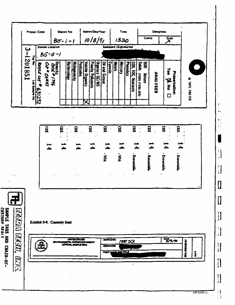
Cod*
c
00en
Station No Monm/Oay/VMr Timt
J330Camp
SUiwn Local ion SampMn (Signatures)
ISI
^^
s
>
n
into
o
oo3
IO
fa
§ : 8 eM M
8M
3 - 9N . (•»
Exhibtt5-9. CostadySol
AR309812
TETRA TECH SOP #613REV. #1
July, 1997PAGE 1 OF 3
EPA CHAIN OF CUSTODY FORM
A. PURPOSE/SCOPE:
Sample custody is a necessary aspect of ensuring sample integrity. Sample custody isto bemaintained during all sample handling activities. By definition, samples are in custody if they
are in the possession of an authorized individual;• are in the field of vision of an authorized individual; and• are in a secure area or a locked container.
In order to verify sample integrity, written conclusive proof is required that samples arecollected, transferred, prepared, and analyzed in an unbroken chain. That written proof is aChain-of-Custody form.
B. EQUIPMENT/MATERIALS:
Black ink pen, EPA Chain-of-Custody (COC) forms (see attached example).
C. PROCEDURE:
The EPA COC is used to accompany samples that are NOT submitted through the CLP.Examples of when to use this COC form include: samples submitted to CRL's lab (OASQABestgate Road), or DAS labs. In situations where the CLP labs are providing analyticalsupport, use the combined Traffic Report/Chain-of Custody form (SOP #615).
To complete the COC form, the following information must be provided:
• The EPA Case number or DAS Number;
• An abbreviation for the project name; the contract lab is not to be given the full sitename (note: the full site name is used for "in-house" analysis by CRL);
• The sampler's signature;
• The station number (which must be different from the station location);
The date and time the sample was taken;
Whether the sample is composite or grab;
• The number of containers in which the sample has been placed;
• The type of analyses requested;
Under "Remarks" (in the upper right corner of the record), list the DAS Case number
AR309813
TETRA TECH SOP #613REV. #1
July, 1997PAGE 2 OF 3
and the corresponding sample tag numbers;
• Under "Remarks" (in the lower right corner of the record), the airbill number of thecontainer in which the samples will be shipped to the laboratory. (When samples are jshipped to the laboratory via commercial carrier, the airbill serves as an extension of *the chain-of-custody.); and
j• Under "Relinquished by" and "Received by", the signature of every authorized person '
who maintains custody of the samples.j •
D. QA/QC REQUIREMENTS: L
A second person should review all entries before the form is sealed in the sample cooler. pMistakes should be corrected by crossing out the incorrect entry with a single line, initialing [,the line out, and entering the correct entry immediately adjacent to the incorrect entry.
E. SPECIAL CONDITIONS j
None.i
F. REFERENCES:t
None. •
I
AR309814

Users' Guide for Acquiring Analytical ServicesRegion in Client Services Team
June 1999revision 2
Exhibit 4
U.S. EPA REGION 3 CHAIN OF CUSTODY RECORD RECORD No.: PACE: OF
COLUMN •VATK)
N
COLUMN Coc
COLUMN Divrt
COUNT No SAMPLINO OROAMZATION.
l.OBOUND WATER
I HO.1.HN01 (•> CLANK
(GIGRAB(0 COMPOSITE
DATE SHITTED l.LCACMATl4 nELDQC
1 KWOO4-4 H1KV
lOtDUPUCATIWtRINIATC
SAM?LESUSEDKM LAB OC
IIUIN* ATE:4.0a.(HMHONLr) < uoaor
(TOP. EVAL(-)HOOC
STATt SHI? TO 7 WASniHMHONLY)
1.ICEI NONE* onm
(DP) our MRs«eirv
IPMCNT COMPtm? I V / Nl HNAL SHIP DATE TO LAI: TOTAL NinWOI Or SAMPLES MIPPCO: TOTAL NUMBOI OP CONTAINCUPUPPUI:
.IHOUISHKO (Y SICHATURE RECEIVED BY IIONATURI DATE RELINOUI3HEDBY SWNATURC RECEIVED BY SIGNATURE
SAMPLENUMBER
STATIONNUMBER
STATIONLOCATION
TAG COLLECTION PARAMETERS
DATE TIME
COLUMN!
lAMRIUl
LAMETERS1
IAMCTERS>
30
AR309815

TETRA TECH SOP #615REV. #1
July, 1997PAGE 1 OF 5
TRAFFIC REPORT & CHAIN OF CUSTODY FORMS
A. PURPOSE/SCOPE:
Sample custody is a necessary aspect of ensuring sample integrity. Sample custody isto bemaintained during all sample handling activities. By definition, samples are in custody if they
• are in the possession of an authorized individual;are in the field of vision of an authorized individual; and
• are in a secure area or a locked container.
In order to verify sample integrity, written conclusive proof is required that samples arecollected, transferred, prepared, and analyzed in an unbroken chain. That written proof is aChain-of-Custody form.
B. EQUIPMENT/MATERIALS:
For RAS analyses through the CLP, the Chain-of-Custody (COC) form has been combinedwith the sample tracking Traffic Report (TR) form; one form exists for organic samples;asecond form exists for inorganic samples (examples attached). For Non-CLP (e.g., DAS orRAC-procured) analytical support, the CLP paperwork is not to be used. For DAS samplinguse the EPA COC (refer to SOP#613). For labs procured by Tt in support of a RACassignment, a Tt COC form should be used.
C. PROCEDURE:
Refer to the instructions found on the back of the TRCOC . Complete the form using a ball-point pen and press firmly to ensure that the carbon copies are legible.
The following information must be provided to complete the Traffic Report/Chain-of-Custodyforms; numbers and letters correspond to the boxes on the Report Forms:
The top line has space to provide the SAS No. (No longer used - ignore this space) and theCLP case number.
(1) Project information including:
• the Project Code;• the Site Name;• the City and State of the site; and• the Site Spill ID number (if any).
(2) the USEPA Region Number where the sampling is being performed (Region III) and thename of the Sampling Company and Sampler.
(3) the Type of Activity being conducted (e.g., PA, SI, etc.).
AR309816
TETRA TECH SOP #615REV.#1
July, 1997 IPAGE 2 OF 5 ''
(A) the Date the samples were shipped,, the name of the Carrier and tie Airbill Number for ithe shipping container in which the samples were shipped. * •
(5) the name and address of the laboratory where the samples are being shipped. i
In the central portion of the form, from left to right, list the following:
• the "unique CLP Sample Number"
(A) Sample Description (from Box 7); jli
(B) anticipated Sample Concentration (L=low; M=medium; H=high);
(C) Sample type: Composite or Grab; j j
(D) Sample Preservative (from Box 6);
(E) indicate the RAS analysis requested; ;
(F) the Sample Tag number; ii.
(G) the Station Location number;
(H) the date/time of sample collection; !
(I) the Samplers initials;
(J) the Corresponding CLP organic or inorganic sample number; and "
(K) Designated field QC (use codes on the back of the form). j
In a single line along the bottom of the central part of the form, indicate:
'^e r\r Mr\VIf the entire sample shipment for that Case Number is complete (Yes or No);
• the page number of that sheet relative to the total number of sheets in that shippingcooler;
• the CLP sample number to be used for lab QC (matrix spike/matrix spike duplicatesample - NOT FIELD DUPLICATE);
• Additional samplers signature; and
the Chain-of-Custody Seal Number (not applicable at this time).
The lower portion of the form is the Chain-of-Custody Record. The signature of the sampler,the date, and the time must be filled in before the paperwork is sealedin the shipping cooler.
D. QA/QC REQUIREMENTS:
AR309817
TETRA TECH SOP #615REV. #1
July, 1997PAGE 3 OF 5
A second person should review all entries before the form is sealed in the sample cooler.Mistakes should be corrected by crossing out the incorrect entry with a single line, initialingthe line out, and entering the correct entry immediately adjacent to the incorrect entry.
E. SPECIAL CONDITIONS
None.
F. REFERENCES:
Refer to Sampler's Guide to the CLP (EPA/540/R-96/032).
AR309818

Exhibit 6
Users' Guide for Acquiring Analytical ServicesRegion III Client Services Team
June 1999revision 2
wEPAOrganic Traffic R
& Chain of Custody(ForOtparteCU'Anelyata)
CataNe.
AeceuntCOM
Ragnntl Intonation
Naiv6upir<und Program
Ki/A
Z Region N
3 Aw. »- IS- *r7Sampler (Ntam)
Volome.Samper Signatures*\l, nt *-ui^ \
AMUINumter
333S. Ship To
Lflto
6. Matrix(CnwrM Column A;1. Surtaea Watar2. Qround Watar3. Laaahaia4. Flald QC5. SoH/Sadlmant
<*old«n, toIn Column A)
R*gteialSpM«eTmcWm NumberarTagNumMn
Qato
Location
HUalDqt
Vm/Itai*Sampto
OP InorganicnptoNo.
7.m
Column D)1. HCI2. HNO33. NaHSO44. H2SO45. lea only6. Other
(Spmcity inColumn O)
N. Mot
KFhMOC
to It-to+VMlO-OI 1io9 ra. j&t
CAT 13. MUD-O2. i4X X -O 1 l-I9.fr
i4 So • /TTft-o(
£aQ3SCaU^Bafl
HpmanitorCaaaf
(Ll\Tl4
AddWonal Samplar SlgnatuiM Cham o( Cuaiody Saal NumbaKa)
CHAIN OF CUSTODY RECORDlalmqiMhad by: (Slgnuun) Data/Time
/(/V61f!=
Raeavadby: (Signttun) RaHnquahadby: Data/Time Raotwadoy:
(Sionftum) Raotfwdoy: RaKnquiahadoy: Oaia/Hma Haoawadby: (Signuumi
|Date/Time Date/Time lacuatodyaaalMaet? YMtaona |
\5!•nuaimoN: an MVBMI ran ADomoNu.aTkMum uamucno«u
32
AR309819
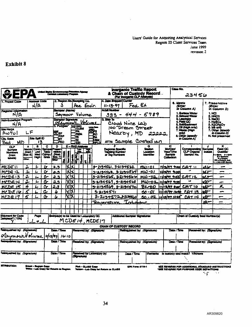
Users' Guide for Acquiring Analytical ServicesRegion III Client Services Team
June 1999revision 2
Exhibit 8
V-/EPA raffic Reportof Custody Reeord
(Forlnoio«iloCU»
CMS No.
I.PrejaciCod* Cod*
Regional intaRMtton
Ctty.SUUe•fend.
StteSpiaiD13
Z Region NajSempingCa
Ate. 1
Saymouc Volume/Sampler SIgrauun&QJjLfrM&t£L-
REMRl61£5L B£U2l
4. OM stripped
AMU NumberFeet. EX.
r«*T5diood Lob
tNfD
6. Matrix(EnterlaCotuainA)LSunaoe WaterZQfDMdWtier
4.HeWQC5.SoOTedlmem6.0l(l«ohenly)
ATTrt
arty)Ottwrft Column X
7. Pra*«rv«liv*(£/»»/•m Column 0)1.HO2.HNO33-ftaOH4.H2S04ft K jC6« ICQ7. Ottwr I
InCotuamO}
CLPSampl*
Numbam(from
AUaifte(bam
Box 6)
Cane, aJVpi
HighCompJ (hornQiab Bo*?]
E-HASAnaWa
Ii
Traddna NumberorTmgMumMra
CoHMtlon
CotTMoondinDCLPOiguileSamplaNa
KFteWQC
H/0/97 UOO CAT II
12. MtO'D/ ll/W17 1:00
fr
uO^DSL »y<i/<yMtO-N\10-02_BtrOO
>M' <LftT7 3- 60-02. i/13/yy //:«* &AT i4
*•««• Ctwkia(Cu«eeV8MlNumb«i(i) JCHAIN (V CUSTODY HKORO
FtaanqulclMd by. (Signmtun) t/TtaM rWtaquWMdby: (Stgtwun) Oata/TkM
(Signttun) RMMMdby: (Signttum) fMnquMMdby: (SlgnUun)
FUinqiwtwdby; /Tbm MMhMd tar Ubomioy by:^
Data/Time RMMifc* IteuModyMalbittcl? Y/Nmoiw
nmnavnON: OraM-llaflaaCapyC««v tar lUttim M CLAM
aac MVBME ran AOOIIIONAL mNOAno mrmucnoMS
T
34
AR309820
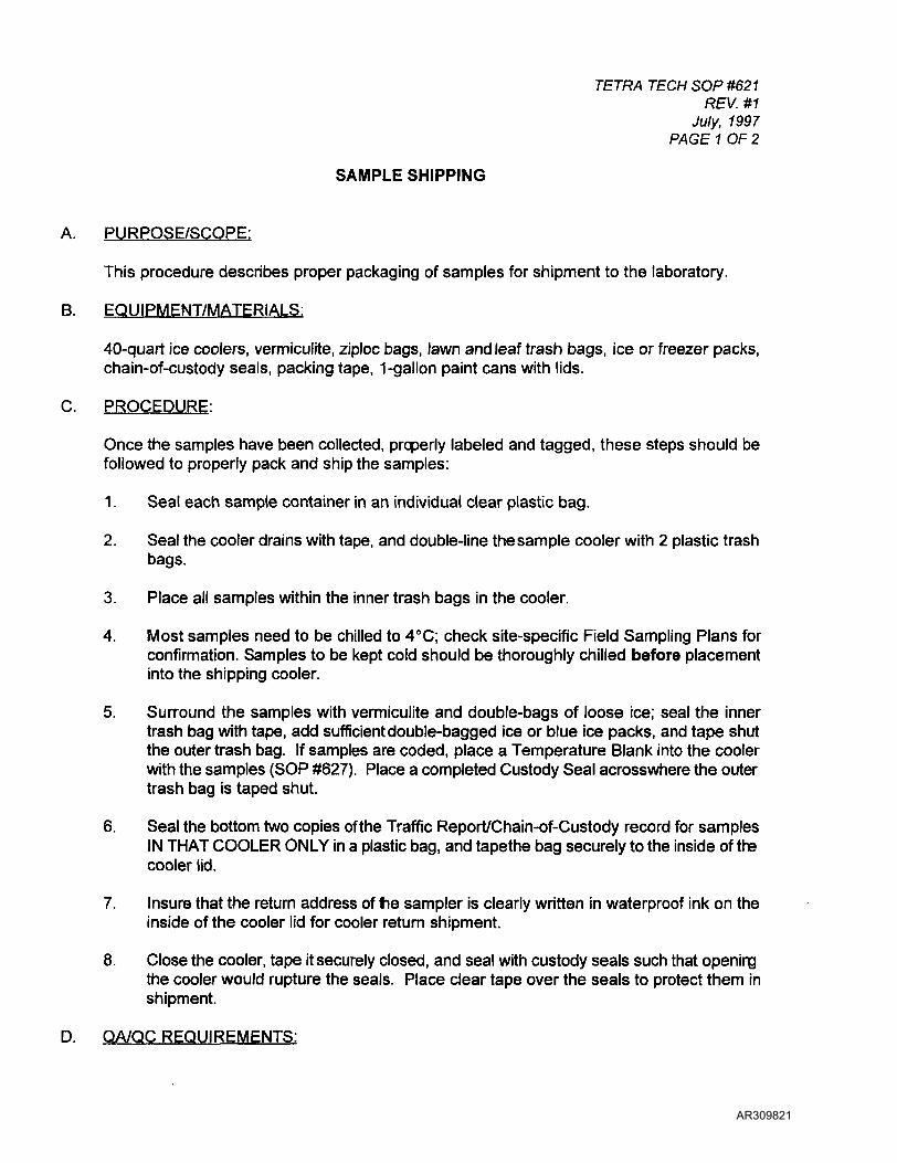
TETRA TECH SOP #621REV. #1
July, 1997PAGE 1 OF 2
SAMPLE SHIPPING
A. PURPOSE/SCOPE:
This procedure describes proper packaging of samples for shipment to the laboratory.
B. EQUIPMENT/MATERIALS:
40-quart ice coolers, vermiculite, ziploc bags, lawn and leaf trash bags, ice or freezer packs,chain-of-custody seals, packing tape, 1-gallon paint cans with lids.
C. PROCEDURE:
Once the samples have been collected, properly labeled and tagged, these steps should befollowed to properly pack and ship the samples:
1. Seal each sample container in an individual clear plastic bag.
2. Seal the cooler drains with tape, and double-line the sample cooler with 2 plastic trashbags.
3. Place all samples within the inner trash bags in the cooler.
4. Most samples need to be chilled to 4°C; check site-specific Field Sampling Plans forconfirmation. Samples to be kept cold should be thoroughly chilled before placementinto the shipping cooler.
5. Surround the samples with vermiculite and double-bags of loose ice; seal the innertrash bag with tape, add sufficient double-bagged ice or blue ice packs, and tape shutthe outer trash bag. If samples are coded, place a Temperature Blank into the coolerwith the samples (SOP #627). Place a completed Custody Seal acrosswhere the outertrash bag is taped shut.
6. Seal the bottom two copies ofthe Traffic Report/Chain-of-Custody record for samplesIN THAT COOLER ONLY in a plastic bag, and tapethe bag securely to the inside ofthecooler lid.
7. Insure that the return address of fie sampler is clearly written in waterproof ink on theinside of the cooler lid for cooler return shipment.
8. Close the cooler, tape it securely closed, and seal with custody seals such that openingthe cooler would rupture the seals. Place clear tape over the seals to protect them inshipment.
D. QA/QC REQUIREMENTS:
AR309821
TETRA TECH SOP #627REV. #1
July, 1997PAGE 2 OF 2
None.
E. SPECIAL CONDITIONS
Pack any medium and high level organic samples and dioxin samples in metal paint cans.The paint cans should be labelled with sample number of sample contained inside and thecontents of the can should be surrounded with vermiculite.
F. REFERENCES:
Sampler's Guide to the CLP (EPA/540/R-96/032); EPA Region III User's Guide, November1997.
I
I
f
AR309822
SOP #623REV. #3
August 2000PAGE 1 OF 2
REPORTING SAMPLE SHIPMENT
A. PURPOSE/SCOPE:
To notify the authorized personnel, as directed, of all sample shipping information on adaily basis. Samples shipped to a CLP lab should be reported to the Contract LaboratoryAnalytical Services Support (CLASS) contractor. Samples sent to a non-CLP lab(including EPA's lab) should be reported to the OAQSQ Client Services Team.
B. EQUIPMENT/MATERIALS:
Copies of this SOP and sample TR/COC forms (RAS samples) or EPA COG form (DASsamples) for reference.
C. PROCEDURE:
1. RAS SAMPLE INFORMATION: The sampler is to call the CLASS contractorimmediately after shipping samples. The telephone number listed on the back sideof the TR/COC form (703- 519-1200) IS NOT CORRECT!!. Call Caroline Mack at(703-264-9323).
2. DAS SAMPLE INFORMATION: The sampler is to call EPA CST immediately aftershipping samples; Betty Ann Jeffery at 410-305-2601.
Give the following information:
Sampler's name, region, and phone number;The case number of the project;Exact number, matrices, and concentrations (estimated; high, medium, low) ofsamples shipped;The analyses to be performed;Name of laboratory(ies) where samples were shipped;The name of the commercial carrier and the airbill numbers;Date of shipment;Suspected contaminants (e.g., dioxins, radiochemicals, etc.);Any information relevant to changes, delays, etc. regarding the sampling project.Whether shipping is complete for the case number.
You may encounter an automated phone mail system. For RAS sample info to CLASS, if youare directed to phone mail, leave all information listed above as part of message; verify theirreceipt of message as soon as possible (e.g., the following morning). For DAS sample info toEPA CST, the above pertain EXCEPT REGARDING SATURDAY DELIVERY OF SAMPLES(see Special Condition section, below).
AR309823

SOP #623REV. #3
August 2000PAGE 2 OF 2 j
D. QA/QC: }
Document the phone communication on a "Record of Telephone Conversation Log."
E. SPECIAL CONDITIONS: i
CLASS must be notified by 3:00 pm EST on Friday if samples are intended for Saturday >delivery to a CLP lab. If shipping DAS samples on a Friday, get written confirmation (such Ias e-mail) on Thursday or before shipping on Friday from CST or EPAs lab regardingconfirmation that the lab is aware of the Saturday delivery. If unable to receive ;confirmation, maintain custody of the samples in a secure refrigerator until Monday \morning, then pack and ship the samples. If the samples to be collected on Friday arescheduled to go to EPA's lab for analysis, call EPA's lab (Pat Sosinski @410-305-2667) .before shipping the samples to ensure that they have made special preparations for a jSaturday delivery (they are typically closed on Saturdays).
H. REFERENCES:
Sampler's Guide to the CLP (EPA/540/R-96/032); EPA Region III Users' Guide toAcquiring Analytical Services (June 1999).
I
I
AR309824
OCCIDENTAL CHEMICALRA OVERSIGHT FSP, REV 3
NOVEMBER 2000
ATTACHMENT 2SCHEMA TIC MONITORING
WELL DETAIL
AR309825
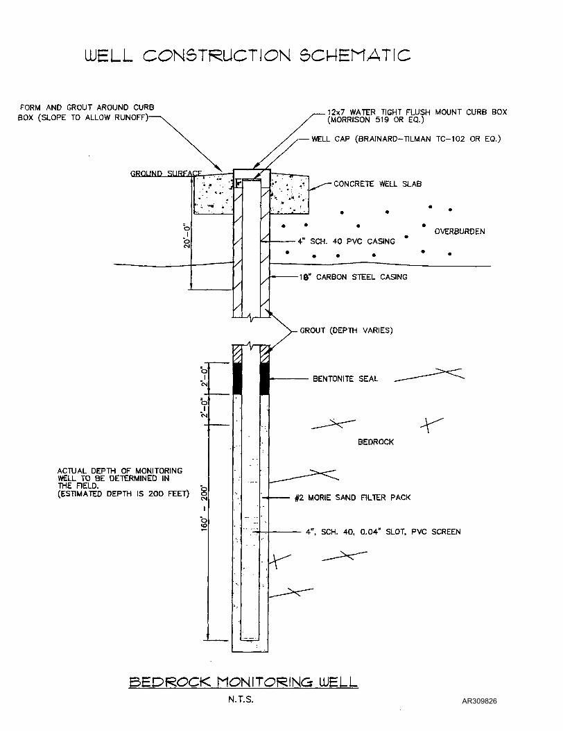
LUELL CONSTRUCTION 5CMEMATIC
FORM AND GROUT AROUND CURBBOX (SLOPE TO ALLOW RUNOFF)-
12x7 WATER TIGHT FLUSH MOUNT CURB BOX(MORRISON 519 OR EQ.)
WELL CAP (BRAINARD-TILMAN TC-102 OR EQ.)
nrnjunii.1 junri-
O
0(N
*rr^/.• .' •• J
' . * * ••• • * '
" ; •••' « * •
E/
/
/
/
/
/
rn
_/»_
/
/
/
/
/
/>
•• • •*•' . . •-. ^-CONCRETE WELL SLAB
% ' ^. 'V
• • * - , ' , . . • •
OVERBURDEN4" PU 4.n PVP r*A^iwp
. .
10" CARBON STEEL CASING
"k
ACTUAL DEPTH OF MONITORINGWELL TO BE DETERMINED INTHE FIELD. Q(ESTIMATED DEPTH IS 200 FEET) o
GROUT (DEPTH VARIES)
BEDROCK
§2 MORIE SAND FILTER PACK
4". SCH. 40, 0.04" SLOT, PVC
BEDROCK MONITORING LUELLN.T.S. AR309826