t2 tibial - az621074.vo.msecnd.net
TRANSCRIPT

T2 Tibial
Operative Technique
Tib
ial Fra
ctu
res
Nailing System

2
This publication sets forth detailed recommended procedures for using Stryker Osteosynthesis devices and instruments.
It offers guidance that you should heed, but, as with any such technical guide, each surgeon must consider the particular needs of each patient and make appropriate adjustments when and as required.
A workshop training is required prior to first surgery.
All non-sterile devices must be cleaned and sterilized before use. Follow the instructions provided in our reprocessing guide (L24002000). Multi-component instruments must be disassembled for cleaning. Please refer to the corresponding assembly/disassembly instructions.
See package insert (L22000007) for a complete list of potential adverse effects, contraindications, warnings and precautions. The surgeon must discuss all relevant risks, including the finite lifetime of the device, with the patient, when necessary.
Warning – Fixation Screws: Stryker Osteosynthesis bone screws are not approved or intended for screw attachment or fixation to the posterior elements (pedicles) of the cervical, thoracic or lumbar spine.
Contributing SurgeonsProf. Dr. med. Volker BührenChief of Surgical Services Medical Director of Murnau Trauma Center Murnau, Germany
Kyle F. Dickson, MD, MBAProfessor and Chairman University of Texas Medical School at Houston Department of Orthopaedic Surgery Houston, Texas USA
Paul Tornetta, III, M. D.Director of Orthopaedic Trauma, Boston Medical Center Professor and Vice Chairman Department of Orthopaedic Surgery Boston University School of Medicine Boston, Massachusetts USA
T2 Tibial Nailing System

3
Contents Page1. Technical Details 4 Technical Details 5 References 52. Indications, Precautions & Contraindications 6 Indications 6 Precautions 6 Relative Contraindications 63. Pre-operative Planning 74. Operative Technique 8 Patient Positioning Options and Reduction 8 Incision 8 Entry Point 9 Unreamed Technique 10 Reamed Technique 10 Nail Selection 12 Nail Insertion 13 Guided Locking Mode (via Target Device) 16 Static Locking Mode 17 Freehand Distal Locking 20 End Cap Insertion 21 Dynamic Locking Mode 22 Apposition /Compression Locking Mode 23 Advanced Locking Mode 24 Nail Removal 25 8mm End Cap & Blocking Screw Technique 26 Blocking Screw Technique (optional) 27

4
T2 NailsDiameters 8*–15mmSizes 240–420mm
10 ° A / P slope
Compression Range**
Herzog Bend, 10 °Both Nails
25
15
50mm
Distal Bend, 4 °(All Three Nails)
60mm
Standard
Technical Details
Nails
5.0mm Fully ThreadedLocking ScrewsL = 25–120mm
4.0mm Fully ThreadedLocking Screws for 8mm Nails (Distal Holes Only)L = 20–60mm
5.0mm Partially Threaded Locking Screws(Shaft Screws)L = 25–120mm
Tibia AdvancedCompression Screw
* 8mm nails require 4mm Fully Threaded Screws for Distal Locking
+ Distal Nails are available as special order implants
Note: Screw Length is measured from
top of head to tip. Dimensions are nominal.
End Caps
Standard +5mm +10mm +15mm
** Compression Range Total Length of Slot 12mm Less Screw Diameter (-) 5mm
Maximum Movement of Screw 7mm
+20mm +25mm +30mm +35mm
Fully Threaded
0mm
31.5
50
34
41Slot
1724
+ Distal
0mm
1724
4148
50.5
Compression Range**
5
Technical Details
References1. Tibial Portal Placement: The
Radiographic Correlate of the Anatomic Safe Zone, Timothy McConnell, Paul Tornetta III, John Tizley, David Casey, Journal of Orthopaedic Trauma, Vol. 15, No. 3, pp. 207-209.
2. Stedtfeld H.-W., Rapke C., Jurowich B. Besonder heiten der Verriegelungsnagelung proximaler Tibiaschaftfrakturen. Osteosynthese International 1995; 4: 264-270.
3. Stedtfeld H.-W. Die transmedulläre Stützschraube. Osteosynthese International (Suppl 1) 2000; 8: 170-172.
A major advantage of the instrument system is a breakthrough in the integration of the instrument platform which can be used for the complete T2 Nailing System, thereby to help reduce complexity and inventory.
The innovative instrument platform offers advanced precision and usability, and features ergonomically styled targeting devices.
Symbol coding on the instruments indicates the type of procedure, and must not be mixed.
Symbol
Square = Long instruments
Triangular = Short instruments
6
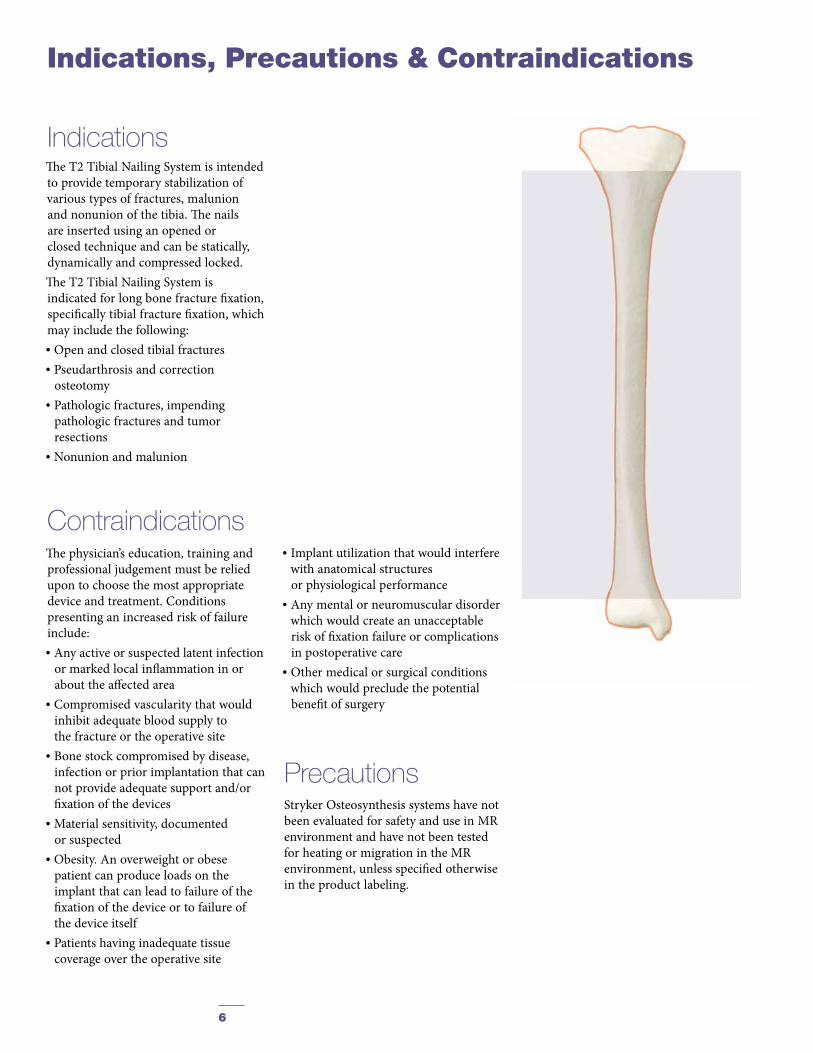
The T2 Tibial Nailing System is intended to provide temporary stabilization of various types of fractures, malunion and nonunion of the tibia. The nails are inserted using an opened or closed technique and can be statically, dynamically and compressed locked.The T2 Tibial Nailing System is indicated for long bone fracture fixation, specifically tibial fracture fixation, which may include the following:• Open and closed tibial fractures• Pseudarthrosis and correction
osteotomy• Pathologic fractures, impending
pathologic fractures and tumor resections
• Nonunion and malunion
Stryker Osteosynthesis systems have not been evaluated for safety and use in MR environment and have not been tested for heating or migration in the MR environment, unless specified otherwise in the product labeling.
Indications
Precautions
Indications, Precautions & Contraindications
ContraindicationsThe physician’s education, training and professional judgement must be relied upon to choose the most appropriate device and treatment. Conditions presenting an increased risk of failure include:• Any active or suspected latent infection
or marked local inflammation in or about the affected area
• Compromised vascularity that would inhibit adequate blood supply to the fracture or the operative site
• Bone stock compromised by disease, infection or prior implantation that can not provide adequate support and/or fixation of the devices
• Material sensitivity, documented or suspected
• Obesity. An overweight or obese patient can produce loads on the implant that can lead to failure of the fixation of the device or to failure of the device itself
• Patients having inadequate tissue coverage over the operative site
• Implant utilization that would interfere with anatomical structures or physiological performance
• Any mental or neuromuscular disorder which would create an unacceptable risk of fixation failure or complications in postoperative care
• Other medical or surgical conditions which would preclude the potential benefit of surgery
7
Pre-Operative Planning
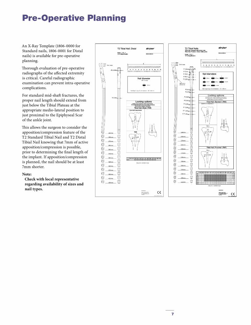
An X-Ray Template (1806-0000 for Standard nails, 1806-0001 for Distal nails) is available for pre-operative planning.
Thorough evaluation of pre-operative radiographs of the affected extremity is critical. Careful radiographic examination can prevent intra-operative complications.
For standard mid-shaft fractures, the proper nail length should extend from just below the Tibial Plateau at the appropriate medio-lateral position to just proximal to the Epiphyseal Scar of the ankle joint.
This allows the surgeon to consider the apposition/compression feature of the T2 Standard Tibial Nail and T2 Distal Tibial Nail knowing that 7mm of active apposition/compression is possible, prior to determining the final length of the implant. If ap po sition/compression is planned, the nail should be at least 7mm shorter.
Note: Check with local representative
regarding availability of sizes and nail types.
8
Fig. 1
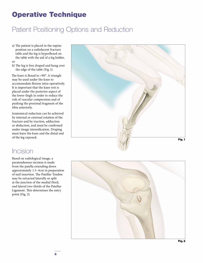
a) The patient is placed in the supine position on a radiolucent fracture table and the leg is hyperflexed on the table with the aid of a leg holder,
or b) The leg is free draped and hung over
the edge of the table (Fig. 1).
The knee is flexed to >90°. A triangle may be used under the knee to accommodate flexion intra-operatively. It is important that the knee rest is placed under the posterior aspect of the lower thigh in order to reduce the risk of vascular compression and of pushing the proximal fragment of the tibia anteriorly.
Anatomical reduction can be achieved by internal or external rotation of the fracture and by traction, adduction or abduction, and must be confirmed under image intensification. Draping must leave the knee and the distal end of the leg exposed.
IncisionBased on radiological image, a paratendenous incision is made from the patella extending down approximately 1.5–4cm in preparation of nail insertion. The Patellar Tendon may be retracted laterally or split at the junction of the medial third, and lateral two-thirds of the Patellar Ligament. This determines the entry point (Fig. 2).
Patient Positioning Options and Reduction
Operative Technique
Fig. 2
9
Fig. 5Fig. 4
Operative Technique
L M
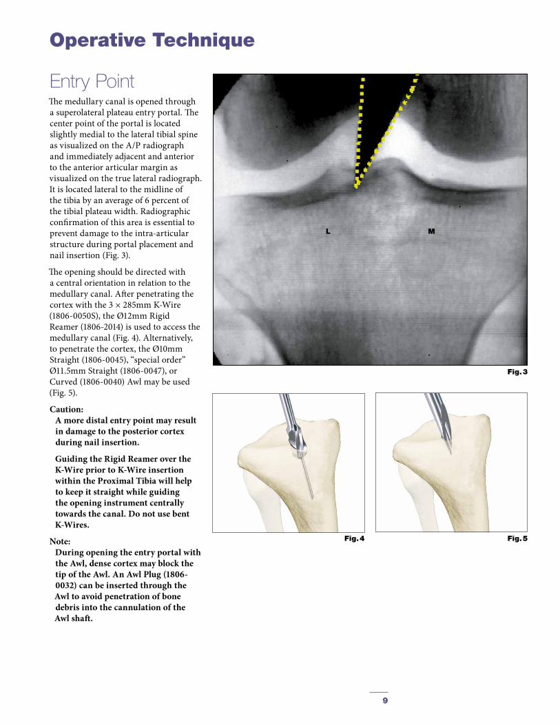
Entry PointThe medullary canal is opened through a superolateral plateau entry portal. The center point of the portal is located slightly medial to the lateral tibial spine as visualized on the A/P radiograph and immediately adjacent and anterior to the anterior articular margin as visualized on the true lateral radiograph. It is located lateral to the midline of the tibia by an average of 6 percent of the tibial plateau width. Radiographic confirmation of this area is essential to prevent damage to the intra-articular structure during portal placement and nail insertion (Fig. 3).
The opening should be directed with a central orientation in relation to the medullary canal. After penetrating the cortex with the 3 × 285mm K-Wire (1806-0050S), the Ø12mm Rigid Reamer (1806-2014) is used to access the medullary canal (Fig. 4). Alternatively, to penetrate the cortex, the Ø10mm Straight (1806-0045), “special order” Ø11.5mm Straight (1806-0047), or Curved (1806-0040) Awl may be used (Fig. 5).
Caution: A more distal entry point may result
in damage to the posterior cortex during nail insertion.
Guiding the Rigid Reamer over the K-Wire prior to K-Wire insertion within the Proximal Tibia will help to keep it straight while guiding the opening instrument centrally towards the canal. Do not use bent K-Wires.
Note: During opening the entry portal with
the Awl, dense cortex may block the tip of the Awl. An Awl Plug (1806-0032) can be inserted through the Awl to avoid penetration of bone debris into the cannulation of the Awl shaft.
Fig. 3

10
Fig. 8
For reamed techniques, the 3 × 800mm Ball Tip Guide Wire (1806-0080S) is inserted through the fracture site. Except for the 8mm Tibial Nails, use of the Ball Tip Guide Wire does not require a Guide Wire exchange. The Universal Rod with Reduction Spoon may be used as a fracture reduction tool to facilitate Guide Wire insertion through the fracture site (see Fig. 7).
Note: The Ball Tip at the end of the Guide
Wire will stop the reamer head.
Reaming (Fig. 8) is commenced in 0.5mm increments until cortical contact is appreciated. Final reaming should be 1mm –1.5mm larger than the diameter of the nail to be used.
If an unreamed technique is preferred, the 3 × 800mm Smooth Tip Guide Wire (1806-0090S) is passed through the fracture site using the Guide Wire Handle (1806-1095) (Fig. 6). The Universal Rod (1806-0110) with Reduction Spoon (1806-0125) may be used as a fracture reduction tool to facilitate Guide Wire insertion (Fig. 7), and as a “sound” to help determine the diameter of the medullary canal. The Universal Rod is 9mm in diameter. Internal rotation during insertion will aid in passing the Guide Wire down the tibial shaft. The Guide Wire should lie in the center of the metaphysis and the diaphysis in both the A/P and Lateral views to avoid offset positioning of the nail. The Guide Wire handle is removed leaving the Guide Wire in place.
Unreamed Technique
Reamed Technique
Fig. 6
Fig. 7
Operative Technique
11
Fig. 9
Fig. 10
Operative Technique
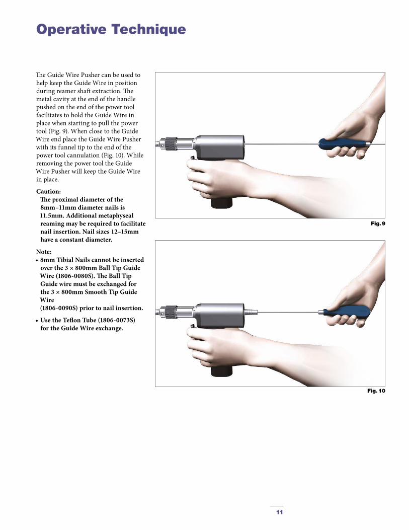
The Guide Wire Pusher can be used to help keep the Guide Wire in position during reamer shaft extraction. The metal cavity at the end of the handle pushed on the end of the power tool facilitates to hold the Guide Wire in place when starting to pull the power tool (Fig. 9). When close to the Guide Wire end place the Guide Wire Pusher with its funnel tip to the end of the power tool cannulation (Fig. 10). While removing the power tool the Guide Wire Pusher will keep the Guide Wire in place.
Caution: The proximal diameter of the
8mm –11mm diameter nails is 11.5mm. Additional metaphyseal reaming may be required to facilitate nail insertion. Nail sizes 12–15mm have a constant diameter.
Note: • 8mm Tibial Nails cannot be inserted
over the 3 × 800mm Ball Tip Guide Wire (1806-0080S). The Ball Tip Guide wire must be exchanged for the 3 × 800mm Smooth Tip Guide Wire (1806-0090S) prior to nail insertion.
• Use the Teflon Tube (1806-0073S) for the Guide Wire exchange.
12
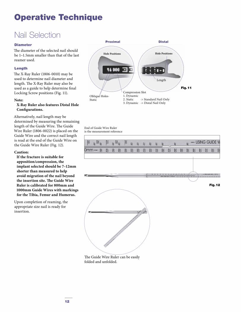
End of Guide Wire Ruleris the measurement reference
Hole Positions
Fig. 11Compression Slot1. Dynamic2. Static -> Standard Nail Only 3. Dynamic -> Distal Nail Only
Oblique Holes-Static
Proximal Distal
Length
Hole Positions
Nail SelectionDiameter
The diameter of the selected nail should be 1–1.5mm smaller than that of the last reamer used.
Length
The X-Ray Ruler (1806-0010) may be used to determine nail diameter and length. The X-Ray Ruler may also be used as a guide to help determine final Locking Screw positions (Fig. 11).
Note: X-Ray Ruler also features Distal Hole
Configurations.
Alternatively, nail length may be determined by measuring the remaining length of the Guide Wire. The Guide Wire Ruler (1806-0022) is placed on the Guide Wire and the correct nail length is read at the end of the Guide Wire on the Guide Wire Ruler (Fig. 12).
Caution: If the fracture is suitable for
appo sition/compression, the implant selected should be 7–12mm shorter than measured to help avoid migration of the nail beyond the insertion site. The Guide Wire Ruler is calibrated for 800mm and 1000mm Guide Wires with markings for the Tibia, Femur and Humerus.
Upon completion of reaming, the appropriate size nail is ready for insertion.
Operative Technique
Fig. 12
The Guide Wire Ruler can be easily folded and unfolded.

13
Operative Technique
Strike Plate
Nail Holding Screw
Nail Adapter
Targeting Arm
Fig. 13
Nail InsertionThe selected nail is assembled onto the Nail Adapter (1806-1002) with the Nail Holding Screw (1806-0370) (Fig. 13). Securely tighten the Nail Holding Screw with the Insertion Wrench (1806-0135) so that it does not loosen during nail insertion.
To attach the Nail Adapter to the Targeting Arm, turn the Quick-Lock Ring on the Targeting Arm clockwise. Triangles on the Quick-Lock Ring and the Targeting Arm indicate the correct position to attach the Nail Adapter when both triangles are in line with each other.
Caution: Prior to insertion:1. Re-check that the Nail is tightly
secured to the Nail Adapter.2. Ensure that both the head of the
Nail Holding Screw and the driving end of the nail completely align with the Nail Adapter.
3. Verify the hole pattern and appropriate locking options for the Nail type selected. This is extremely important since the proximal hole patterns are different among the Standard and Distal Nails.
4. Check correct alignment by inserting a drill bit through the assembled Tissue Protection - and Drill Sleeve placed in the required holes of the targeting device.
5. T2 Tibial nails with diameters 9mm–15mm do not require a Guide Wire exchange.

14
Fig. 15
Fig. 16
Fig. 14
Operative Technique
If a Guide Wire is used, it is important to note that only the 8mm Tibial Nails require exchanging the 3 × 800mm Ball Tip Guide Wire (1806-0080S) for the 3 × 800mm Smooth-Tip Guide Wire (1806-0090S) prior to insertion. Use the Teflon Tube (1806-0073S) to facilitate the Guide Wire exchange.
The Strike Plate (1806-0150) is threaded into the Nail Adapter next to the Nail Holding Screw.
The Nail is inserted by hand over the 3 × 800mm Ball Tip Guide Wire (if used) and into the entry site of the proximal tibia (Fig. 14). Gently manipulate the nail to help avoid penetration of the posterior cortex. If the nail is deflected towards the posterior cortex, remove the nail, and hyperflex the knee. Under image control, use a straight reamer to ream an anterior tract in the proximal fragment.
The Nail is advanced through the entry point past the fracture site to the appropriate level. Remove the Guide Wire once the nail is past the fracture site.
The Slotted Hammer can be used on the Strike Plate (Fig. 15) or if dense bone is encountered, alternatively, the Universal Rod may be attached to the Strike Plate and used in conjunction with the Slotted Hammer (1806-0170) to insert the nail (Fig. 16).

15
Fig. 17 Fig. 18
12mm compression slot allows 7mm of compression.
Fig. 18a
12mm
7mm
2mm
Apposition/Compression
Static
Dynamic
Fig. 19
Turn silver Quick- Lock Ring Clockwise
Bring Targeting Arm up to Nail Adapter
The three circumferential grooves on the insertion post act as a guide while inserting the nail to the correct depth. When locking the Tibial Nail in the Static Mode, the nail is countersunk a minimum of 2mm to the chondral surface (Fig. 17). When the implant is inserted in the Dynamic Mode, with active apposition/compression or in the Advanced Locking Mode, the recommended insertion depth is 7mm or 12mm based on how much active compression is to be applied (Fig. 18). The final nail depth should be well below the chondral surface to minimize irritation to the Patellar Tendon.
If the nail has been inserted too far, it has to be repositioned. Repositioning of the nail should be carried out either by hand or by using the Strike Plate attached to the Nail Adapter. The Universal Rod and Slotted Hammer may then be attached to the Strike Plate to carefully and smoothly retract the assembly. DO NOT hit on the Target Device.
Attach the Targeting Arm to the Nail Adapter by rotating the spring loaded Quick-Lock Ring on the Target Arm clockwise while connecting it to the knob on the end of the Nail Adapter (Fig. 19).
Note: Remove the Guide Wire prior to
drilling holes and inserting the Locking Screws.
A chamfer is located on the proximal end of the nail to help identify the junction of the nail and insertion post under fluoroscopy. Three circumferential grooves are located on the insertion post of the Target Device Assembly at 2mm, 7mm and 12mm from the proximal end of the nail. Depth of insertion may be visualized with the aid of fluoroscopy.
Caution: Compression Slot on the Distal Nail
is located 7mm further Distal than on the Standard Nail.
Operative Technique

16
(via Target Device)
Before locking the nail proximally, re-check that the Nail Holding Screw is securely tightened by using the Insertion Wrench, and check that the Target Arm is properly attached to the Nail Adapter. The Target Device is designed to provide four options for proximal locking when using the Standard Tibial Nail (Fig. 19.1–19.3).
In Static Locking Mode all three indicated holes may be used (Fig. 19.1).
1. Static 2. Static 3. Static
The dynamic hole is used to lock the nail in the controlled Dynamization or Apposition/Compression Modes (Fig. 19.2).
4. Dynamic
Guided Locking ModeBoth the dynamic and more proximal of the two oblique locking holes are used in the Advanced Locking Mode. Proper placement of the Advanced Compression Screw against the transverse Partially Threaded Locking Screw (Shaft Screw) will block the more distal of the two oblique locking holes even if fully compressed (Fig. 19.3).
4. Dynamic 1. Static
Caution: Any attempt to drill across the more distal of the two oblique locking holes may result in particulate debris generation or a broken drill.
The Long Tissue Protection Sleeve (1806-0185) together with the Long Drill Sleeve (1806-0215) and the Long Trocar (1806-0315) is inserted into the Target Device by pressing the safety clip (Fig. 20). The mechanism will help keep the sleeve in place and help prevent it from falling out.
It will also help prevent the sleeve from sliding during screw measurement. To release the Tissue Protection Sleeve, the safety clip must be pressed again and held while removing the sleeve.
Caution: The location of the oblong hole on the Distal Tibial Nail is 7mm more distal than the hole location for the Standard Tibial Nail. If a Distal Tibial Nail is implanted, do not attempt to drill through the Dynamic M/L hole on the Target Device or you will hit the nail. Only use the static hole numbered 1, 2, and 3. (Fig. 19.1)
Fig. 19.2Fig. 20There are four safety clips
Caution: For Standard and Distal Nail only.
4
Fig. 19.1Fig. 19.3
3
2 1
4
1
released locked
Operative Technique

17
Fig. 21
Fig. 22
For static locking of the Standard Tibial Nail, both proximal oblique screws and the M/L Locking Screw may be used. In highly unstable, comminuted fractures the M/L screw is placed in the static position of the oblong hole. This may further improve stability of the proximal fragment.
If secondary dynamization is planned, the M/L screw may be inserted in the dynamic position of the oblong hole on the Target Device. This allows controlled dynamization of the fracture in cases of delayed union after removal of the proximal oblique screws.
Caution: If secondary dynamization is used
with the Distal Tibial Nail, the M/L screw has to be inserted through the distal most part of the oblong hole the Target Device. (The oblong hole on the Distal Tibial Nail is 7mm more distal than on the Standard Tibial Nail).
Always start with the most distal oblique Fully Threaded Locking Screw. The Long Tissue Protection Sleeve (assembled with the Long Drill Sleeve and Trocar) is positioned through the static locking hole on the Target Device. A small skin incision is made, and while pressing the safety clip, the Tissue Protection Sleeve is pushed through until it is in contact with the anterior cortex (Fig. 21).
Caution: Make sure the Tissue Protection
Sleeve/Drill Sleeve Assembly is seated on bone prior to selecting final screw length.
The Long Trocar is removed, with the Tissue Protection Sleeve and Drill Sleeve remaining in position.
Static Locking Mode
Operative Technique
18
Fig. 23
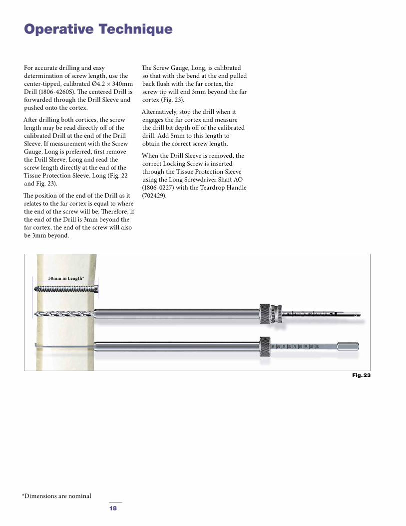
50mm in Length*
Operative Technique
For accurate drilling and easy determination of screw length, use the center-tipped, calibrated Ø4.2 × 340mm Drill (1806-4260S). The centered Drill is forwarded through the Drill Sleeve and pushed onto the cortex.
After drilling both cortices, the screw length may be read directly off of the calibrated Drill at the end of the Drill Sleeve. If measurement with the Screw Gauge, Long is preferred, first remove the Drill Sleeve, Long and read the screw length directly at the end of the Tissue Protection Sleeve, Long (Fig. 22 and Fig. 23).
The position of the end of the Drill as it relates to the far cortex is equal to where the end of the screw will be. Therefore, if the end of the Drill is 3mm beyond the far cortex, the end of the screw will also be 3mm beyond.
The Screw Gauge, Long, is calibrated so that with the bend at the end pulled back flush with the far cortex, the screw tip will end 3mm beyond the far cortex (Fig. 23).
Alternatively, stop the drill when it engages the far cortex and measure the drill bit depth off of the calibrated drill. Add 5mm to this length to obtain the correct screw length.
When the Drill Sleeve is removed, the correct Locking Screw is inserted through the Tissue Protection Sleeve using the Long Screwdriver Shaft AO (1806-0227) with the Teardrop Handle (702429).
*Dimensions are nominal
19
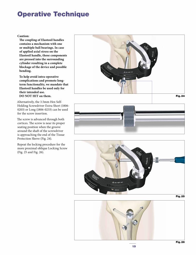
Caution: The coupling of Elastosil handles
contains a mechanism with one or multiple ball bearings. In case of applied axial stress on the Elastosil handle, those components are pressed into the surrounding cylinder resulting in a complete blockage of the device and possible bending.
To help avoid intra-operative complications and promote long-term functionality, we mandate that Elastosil handles be used only for their intended use. DO NOT HIT on them.
Alternatively, the 3.5mm Hex Self-Holding Screwdriver Extra Short (1806-0203) or Long (1806-0233) can be used for the screw insertion.
The screw is advanced through both cortices. The screw is near its proper seating position when the groove around the shaft of the screwdriver is approaching the end of the Tissue Protection Sleeve (Fig. 24).
Repeat the locking procedure for the more proximal oblique Locking Screw (Fig. 25 and Fig. 26).
Fig. 24
Fig. 25
Fig. 26
Operative Technique

20
Fig. 27
Fig. 28
Fig. 29
Fig. 30
The freehand technique is used to insert Locking Screws into both the M/L and A/P holes in the nail. Rotational alignment must be checked prior to locking the nail statically.
Multiple locking techniques and radiolucent drill devices are available for freehand locking. The critical step with any freehand locking technique is to visualize a perfectly round locking hole with the C-Arm.
The center-tipped Ø4.2 × 130mm Drill (1806-4280S) is held at an oblique angle pointing to the center of the locking hole (Fig. 27 and Fig. 28). Upon X-Ray verification, the Drill is placed perpendicular to the nail and drilled through the medial cortex. Confirm in both the A/P and M/L planes by X-Ray that the drill passes through the hole in the nail.
The Screw Gauge, Long (1806-0331) can be used to determine the screw length (Fig. 29).
As detailed in the proximal locking section (Fig. 23, p. 18), the position of the end of the drill is equal to the end of the screw as they relate to the far cortex.
Routine Locking Screw insertion is employed (Fig. 30) with the assembled Screwdriver Shaft and Teardrop Handle. Alternatively, the 3.5mm Hex Self-Holding Screwdriver Extra-short (1806-0203) can be used for the screw insertion.
Note: A fully threaded End Cap is
available to lock down on the most proximal screw and create a fixed angle construct.
Caution: Distal locking should always be
performed with two screws, locking the hole nearest the fracture site first. On the Standard Tibial nails, always lock the most proximal M/L hole. The most distal hole of both nail types is M/L.
Freehand Distal Locking
Operative Technique
The next most proximal hole on both nails is A/P. The Standard Nails have a third more proximal M/L hole.
8mm Tibial Nails must always be locked distally with 4mm Fully Threaded Screws.
For the 8mm Tibial Nails, the Ø3.5 × 130mm Drill (1806-3550S) is used to drill both cortices prior to inserting the 4mm Fully Threaded Locking Screws in the distal holes. With all sizes of T2 Tibial Nails, the 8mm Nails use 5.0mm Screws proximally.

21
Fully Threaded
Fig. 32
Screwdriver Self-holding, Long (3.5) Fig. 33
Standard +5mm +10mm +15mm +20mm +25mm +30mm +35mm
Fig. 31
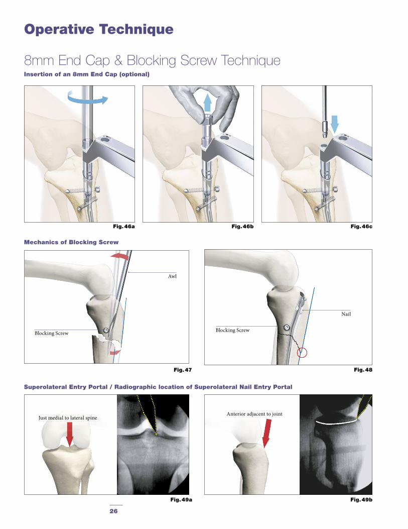
After removal of the Target Device, an End Cap is used. Eight different sizes of End Caps* are available to adjust nail length and to reduce the potential for bony ingrowth into the proximal threads of the nail (Fig. 31).
The End Cap is inserted with the Screwdriver, Self-holding, Long (3.5) after intra-operative radiographs show satisfactory reduction and hardware implantation (Fig. 32 and 33). If the self-holding screwdriver is not available, the Screwdriver Shaft and Teardrop Handle can also be utilized. Fully seat the End Cap to minimize the potential for loosening.
Thoroughly irrigate the wound to prevent debris from remaining within the knee joint. Close the wound using standard technique.
*Optional 8mm diameter End Caps are available in to facilitate insertion through the Nail Adapter (see page 26).
End Cap Insertion
Operative Technique

22
When the fracture profile permits, dynamic locking may be utilized for transverse, axially stable fractures. Controlled dynamization is performed by statically locking the nail distally with at least two screws in a freehand technique.
Note: The Standard Nails each have one
A/P and two M/L distal screw hole options. The Distal Nail has one M/L (the most distal) and one A/P distal screw hole.
In the Dynamic Locking Mode of the Standard Tibial Nail, the Partially Threaded Locking Screw (Shaft Screw) is placed in the dynamic position of the M/L oblong hole (Fig. 34). The two oblique proximal screws are not inserted. This allows the nail to move relative to the Partially Threaded Locking Screw (Shaft Screw) and the fracture to settle while maintaining torsional stability.
For screw insertion, follow the procedure described above (see Fig. 35 and 36).
Caution: When using the Distal Tibial Nail,
the M/L screw has to be inserted in the static position of the oblong hole on the Targeting Device. It is important to note that the position of the oblong hole of this nail is 7mm more distal than on the Standard Nail.
When using the Distal Tibial Nail, static locking of the proximal M/L oblong hole can only be performed freehand.
The proximal end of the nail must be buried at least 7mm–12mm into the bone to reduce the potential for impingement or irritation of the Patellar Tendon if the nail migrates during dynamization.
Dynamic Locking Mode
Fig. 36
Fig. 35
Fig. 34
Operative Technique
23
In transverse or axially stable fracture patterns, active apposition/compression may increase fracture stability, may enhance fracture healing and allow for early weight bearing. The T2 Standard Tibial Nail and T2 Distal Tibial Nail provide the option to treat a tibial fracture with active mechanical apposition/compression prior to leaving the operating room.
Caution: Distal freehand static locking with at
least two screws must be performed prior to applying active, controlled apposition/compression to the fracture site.
If active apposition/compression is required for the T2 Standard Tibial Nail, a Partially Threaded Locking Screw is inserted via the Target Device in the dynamic position of the oblong hole. The Distal Tibial Nail uses the static position of the oblong hole.
This will allow for a maximum of 7mm of active, controlled apposition/compression using the Advanced Compression Screw. In order to insert the Partially Threaded Locking Screw (Shaft Screw), drill both cortices with the Ø4.2 × 340mm Drill (1806-4260S). Correct screw length may be read from the calibration on the Drill at the end of the Drill Sleeve. The near cortex ONLY is overdrilled using the Ø5 × 230mm Drill (1806-5000S).
Note: It may be easier to insert the
compres sion Screw prior to fully seating the nail. Once the nail tip has cleared the fracture site, the guide wire (if used) is withdrawn. With the proximal portion of the nail still not fully seated and extending out of the bone, the Nail Holding Screw is removed and the Compression Screw is inserted. Care should be taken that the shaft of the Compression Screw does not extend into the area of the oblong hole.
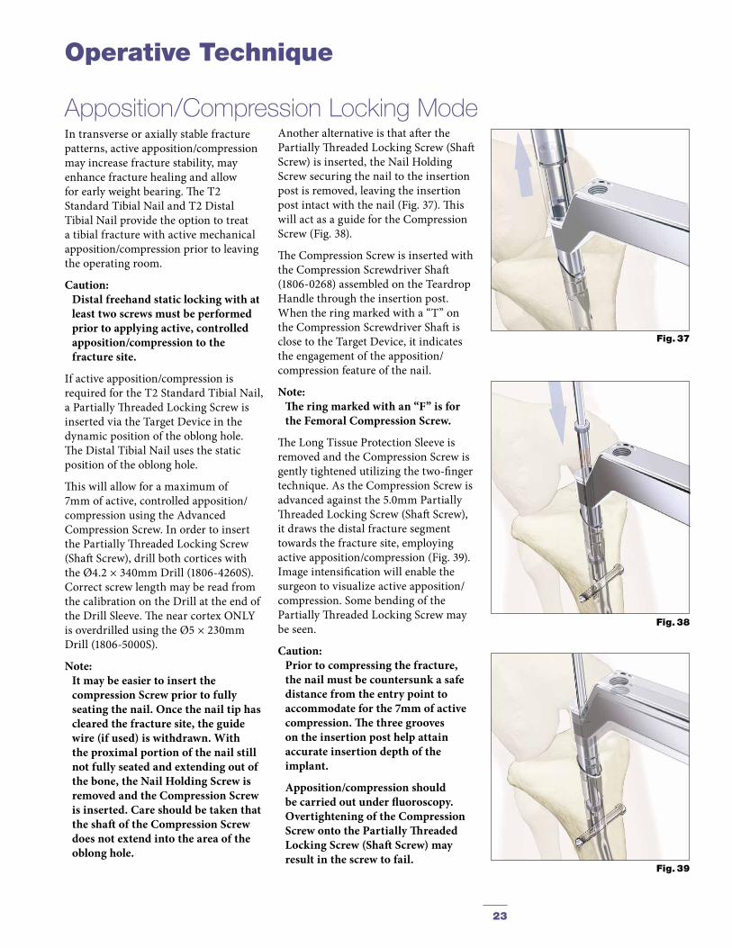
Apposition/Compression Locking ModeAnother alternative is that after the Partially Threaded Locking Screw (Shaft Screw) is inserted, the Nail Holding Screw securing the nail to the insertion post is removed, leaving the insertion post intact with the nail (Fig. 37). This will act as a guide for the Compression Screw (Fig. 38).
The Compression Screw is inserted with the Compression Screwdriver Shaft (1806-0268) assembled on the Teardrop Handle through the insertion post. When the ring marked with a “T” on the Compression Screwdriver Shaft is close to the Target Device, it indicates the engagement of the apposition/compression feature of the nail.
Note: The ring marked with an “F” is for
the Femoral Compression Screw.
The Long Tissue Protection Sleeve is removed and the Compression Screw is gently tightened utilizing the two-finger technique. As the Compression Screw is advanced against the 5.0mm Partially Threaded Locking Screw (Shaft Screw), it draws the distal fracture segment towards the fracture site, employing active apposition/compression (Fig. 39). Image intensification will enable the surgeon to visua l ize active apposition/compres sion. Some bending of the Partially Threaded Locking Screw may be seen.
Caution: Prior to compressing the fracture,
the nail must be countersunk a safe distance from the entry point to accommodate for the 7mm of active compression. The three grooves on the insertion post help attain accurate insertion depth of the implant.
Apposition/compression should be carried out under fluoroscopy. Overtightening of the Compression Screw onto the Partially Threaded Locking Screw (Shaft Screw) may result in the screw to fail.
Fig. 39
Fig. 38
Fig. 37
Operative Technique

24
In order to achieve additional fixation, and to reduce the load on the Partially Threaded Locking Screw, the design of the T2 Standard Tibial Nail and T2 Distal Tibial Nail provide the opportunity to insert an additional Fully Threaded Locking Screw (Shaft Screw) into the more proximal of the two oblique holes after the optimum amount of apposition/compression is attained.
Affix the Compression Screw onto the self-retaining Compression Screw-driver Shaft. Remove the Nail Holding Screw leaving the Target Device in place. Advance the Compression Screw through the Target Device until the ring marked with a “ T ” on the Compres sion Screwdriver Shaft is close to the Target Device and compression is applied (Fig. 40). To insert the Advanced Compression Screw, follow the procedure on page 23.
Note: As previously described, it may be
easier to insert the Compression Screw prior to fully seating the nail.
To re-attach the Target Device, detach the Teardrop Handle from the Compression Screwdriver Shaft and screw the Nail Holding Screw over the Compression Screwdriver Shaft back into position (Fig. 41). Prior to guided locking via the Target Device, the Nail Holding Screw must be securely tightened with the Insertion Wrench.
Caution: When using the Advanced Compres-
sion Screw, only the more proximal oblique hole can be locked with a screw. The more distal oblique hole will be partially blocked by the top of the Advanced Compression Screw regardless of the amount of compression applied to the Shaft Screw in the M/L oblong hole.
To insert the proximal oblique Fully Threaded Locking Screw (Fig. 42), follow the locking procedure for static locking (see Fig. 32 and 33 and on page 17).
Advanced Locking Mode
Fig. 42
Fig. 40
Fig. 41
Operative Technique

25
Nail removal is an elective procedure.
If needed, the End Cap and Advanced Compression Screw are removed with the Screwdriver Shaft and Tear drop Handle. If the Advanced Locking Mode was utilized, first remove the End Cap, then the most proximal screw, then the Advanced Compression Screw can be removed (Fig. 43).
Note: As an alternative to removing the
Advanced Compression Screw (if used), it can be just disengaged from the Partially Threaded Locking Screw (Shaft Screw) by turning the Compression Screwdriver one full turn in a counter-clockwise direction. There is no need to remove it from the nail.
Caution: DO NOT remove the last proximal
Locking Screw prior to attaching the Universal Rod to the proximal end of the nail. Doing so may result in the nail moving posteriorly, making it difficult to attach the Universal Rod to the nail.
The Universal Rod is inserted into the driving end of the nail. All Locking Screws are removed with the Long Screwdriver Shaft and Teardrop Handle (Fig. 44).
Alternatively, the 3.5mm Hex Self-Holding Screwdriver, Long (1806-0233) or Extra Short (1806-0203) can be used for the screw removal.
The Slotted Hammer is used to extract the nail in a controlled manner (Fig. 45).
Note: Stryker offers also a special
Extraction Set for the removal of internal fixation systems and associated screws. Check with your local representative regarding availability of the Universal Extraction Set.
Close the wound in the usual manner.
Nail Removal
Fig. 43
Fig. 44
Fig. 45
Operative Technique
26
Operative Technique
Fig. 47 Fig. 48
Mechanics of Blocking Screw
Superolateral Entry Portal / Radiographic location of Superolateral Nail Entry Portal
Fig. 49b
Blocking Screw
Awl
Nail
Blocking Screw
Insertion of an 8mm End Cap (optional)
Fig. 46a Fig. 46b Fig. 46c
Fig. 49a
8mm End Cap & Blocking Screw Technique
Anterior adjacent to jointJust medial to lateral spine

27
The nail often sits against the posterior cortex which causes anterior angulation of the fracture because the shaft position is fixed by the nail (Fig. 50).
For Varus/ Valgus Adjustment
One of the advantages of the very proximal bend in the nail, is its usefulness in correcting varus/valgus angulation. Do not lock the nail distally until after angular correction. Place the Blocking
The principle of the use of a Blocking Screw is to prevent posterior nail passage by decreasing the effective diameter of the canal and directing the nail more anterior as shown (Fig. 51).
Using the superolateral entry point and with the Blocking Screw in place, the nail accurately aligns the shaft (fracture) (Fig. 52) (1, 2, 3)
Fig. 51
Blocking Screw
Placed to PreventNail passage
Fig. 52
Fig. 53a Fig. 53b Fig. 53c
Blocking Screw
Cross Locking ScrewsBlocking Screw
10° Herzog Bend
Screw at the level of the Proximal (Herzog) Bend (Fig. 53a). In cases where a Blocking Screw is used, simple rotation of the nail (Fig. 53b) will allow the Herzog Bend to correct the angulation (Fig. 53c).
Note: As an option, or in an exchange/
revision nailing with a more distal entry portal, this principal can also be applied with a Lateral Blocking Screw placed A/P as an alternative method to help prevent Varus/Valgus deformity.
Fig. 50
Blocking Screw Technique (optional)
Operative Technique
Superolateral Entry Portal / Radiographic location of Superolateral Nail Entry Portal

28
Notes

29
Notes

30
Notes

31
Notes

This document is intended solely for the use of healthcare professionals. A surgeon must always rely on his or her own professional clinical judgment when deciding whether to use a particular product when treating a particular patient. Stryker does not dispense medical advice and recommends that surgeons be trained in the use of any particular product before using it in surgery.
The information presented is intended to demonstrate a Stryker product. A surgeon must always refer to the package insert, product label and/or instructions for use, including the instructions for Cleaning and Sterilization (if applicable), before using any Stryker product. Products may not be available in all markets because product availability is subject to the regulatory and/or medical practices in individual markets. Please contact your Stryker representative if you have questions about the availability of Stryker products in your area.
Stryker Corporation or its divisions or other corporate affiliated entities own, use or have applied for the following trademarks or service marks: Stryker, T2. All other trademarks are trademarks of their respective owners or holders.
Literature number OUS: B1000005 Rev 9
Literature number US: B1000005-US Rev 2
Content ID: T2-ST-3 Rev 1
Copyright © 2013 Stryker
Manufactured by:Stryker Trauma GmbHProf.-Küntscher-Straße 1–5D - 24232 SchönkirchenGermany
www.osteosynthesis.stryker.com
Distributed by:Stryker Orthopaedics 325 Corporate DrMahwah NJ 07110www.stryker.com