t installation, a maintenance t i & operating g ... · before beginning work on any...
TRANSCRIPT

XTA
GIT
ATO
RM
AN
UA
L
Installation,Maintenance& OperatingInstructionsCLEVELAND MIXERXT Series AgitatorsModels: XT, XTO - Open Tank ModelsXTS/M - Closed Tank ModelsSXTS/M - Side Entry Models
08/08/11 rev. JNCleveland Mixer 2011

TABLE OF CONTENTS
Introduction
Introduction / Contact Info
Uncrating & Inspection
Lifting & Moving
Pre Installation Checklist
Mixer Assembly
Foundation for Installation
Seals
Mounting
Impellers, Shafts, Hardware
Lubrication
High Speed Coupling
Support Beams
Deactivation & Storage
Preventitive Maintenance
Installation, O&M
Operation & Maintenance
Torque Values - Thrust Bolts
Torque Values - Couplings
Impeller Information
Trouble Shooting
Side Entry Information
Parts Breakdown
Spare Parts (general list)
Service Record Log
1
2
2
2
3
3
8 - 11
4 - 7
12 - 17
18 - 21
22
23
24 - 25
25
12 - 13
12 - 13
17
26
22
27 - 28
28
29
Phone: 860-669-1199 or toll free 1-800-243-1188 / 2011 Cleveland Mixerwww.clevelandmixer.comCleveland Mixer4 Heritage Park RoadClinton, CT 06413
1
Cleveland Mixer warrantee applies to only items furnished by Cleveland Mixer. All otherequipment (tanks, mounting structures, power sources, process equipment) & designs arethe responsibility of others. Cleveland Mixer does not warrant, guarantee or assume anyresponsibility for the design or construction of the mounting structure for the mixer.
For questions, tech support or parts & service:
Phone: 860-669-1199 or toll free 800-243-1188Fax: 860-669-7461Email: [email protected]
HOW TO CONTACT US
WARRANTY
Cleveland Mixer Warrantee - For a period of one year from the date of shipment, the productdescribed herein will successfully deliver its rated output as indicated in the quotation,provided it is properly installed, maintained, correctly lubricated and operated in theenvironment within the limits of speed, torque or other load conditions for which it wasdesigned. Unapproved modifications to the equipment and/or running the equipment in anyother way than what it was originally designed for voids the warrantee.
Operate XT Mixers only at the horsepower and speed indicated on the nameplate. ConsultCleveland Mixer before making any changes in operating conditions of XT units, differingfrom "as built".
INTRODUCTION
XT Mixers are engineered and built specifically to handle the unique and demandingrequirements of mixing applications. The worm gear reducer is designed for tough mixingrequirements in industries like chemical processing, food processing, pulp & paper,pharmaceutical, power generation, mining and waste water treatment.
To obtain maximum performance and trouble free service from this Cleveland equipment,follow all instructions carefully. This unit should not be used for any purpose other than theservice for which it was originally designed.
XT Mixers that have gear reducers with an integral drywell guard on the output shaft must bekept in an upright vertical position prior to being filed with oil. Care must be taken whenhandling oil filled drywell reducers to ensure that oil is not allowed to spill over the drywellguard.

2
INSTALLATION
Uncrating & Inspection
Be sure to use care when uncrating andhandling the mixer. Certain parts suchas turbine hubs, turbine blades,couplings, steady bearings, seals,hardware, spare parts and accessoriesmay be packed in boxes or inside of thecrate.
Make sure all components areaccounted for before disgarding thepackaging materials or crates. It iscommon for parts to be missed oroverlooked.
The mixer should be carefully checkedfor possible shipping damage at time ofdelivery. Any damage should bereported immediately to theTRANSPORTATION COMPANY ANDCLEVELAND MIXER.
Improper handling may cause damageto the mixer and seriously reduce theservice life. The shaft has beenstraightened to within .003". Extra careshould be taken to see that it is notdamaged in the process of uncrating.
Lifting & Moving
Always use a crane, hoist or othermechanical assistance to move XTunits. Exercise care to prevent damagewhen moving. Lift only at designated liftpoints. Insure that adequate safetymeasures are taken to protectpersonnel during transportation. Protectthe mounting surface from damage.
Most mixer operational problems can beavoided by following proper installation andoperation instructions. The following is a list ofsuggestions to help insure proper installationand satisfactory mixer service.
Pre Installation Check List
Before permanently wiring the motor,check for the correct rotation of theshaft. Standard rotation is clockwisewhen looking down from the the top.Gear reducers reverse rotation, takethat into account when wiring. All wiringshould be done by a qualifiedelectrician.
1.
2. Read and follow the instructions of alltags and nameplates before operating.
Check the operating full load motoramperage and voltage before operatingthe mixer.
3.
4. The mixers are designed to run againsta design specific gravity. DO NOT RUNMIXER DRY. Always test run in fluidless than or equal to design specificgravity and viscosity.
When starting the mixer, make surethat the impeller is not buried in solids.
5.
6. When making field changes of motorhorsepower, speed, shaft length,impeller diameter, width, etc., consultwith Cleveland Mixer.
Before beginning work on any installation,make sure you have all required parts. Keepall parts for installation together at all times.
There are two style of agitatorsaddressed in this manual; Open Tankand Closed Tank.Open tank models are typicallymounted to a pair of beams or bridgework that traverses the tank. Thissuperstructure can be eitherindependent from the vessel or anintegral part of the tank itself.
Closed or sealed tank units are typicallymounted on ASA schedule nozzles andincorporate some style of sealingmechanism to contain pressure orrogue emissions.
In either case it is critical that themounting has a solid foundation whichis rigid enough to withstand the torqueof the mixing and the horsepower of themotor. Excess vibration and movementcan cause critical damage to the mixerand tank.
The mixer should be mounted to sitlevel (90° for vertical units and 0°/180°for horizontal side mounted units)
We suggest laser aligning the shaftfrom the hallow output of the reducer tothe bottom of the tank. Shaft alignmentwill help to assure the shaft will run true.You do not want the shaft sitting oneven the slightest angle. An angled ormisaligned shaft can cause excessvibration and speed wobble which cancause critical damage to the mixer andthe tank.
Be sure that the turbine blades canfreely rotate a full 360°. Be sure that theblades will not come in contact with:baffles, dip tubes, tank walls, etc.
3
As previously mentioned; to ensure a longservice life and dependable performance, themixer must be rigidly supported and the shaftaccurately aligned - the shaft should notmove more than 1/32" per foot of shaft due todeflection of the structure. It is important thatthe gear reducer sits level for it's lubricationsystem to work properly. Be sure to take intoaccount where the oil drain plug is beforemounting. The following describes theminimum precautions required to accomplishthis end.
FoundationThe responsibility for the design andconstruction of the foundation lies with theend user. The foundation must be adequateto withstand normal operating loads andpossible overloads while maintainingalignment to attached system componentsunder such loads.
Concrete Foundation
If a concrete foundation is used, steelmounting pads and bolts of sufficient size todistribute the stress into the concrete shouldbe grouted into the foundation.
If a structural steel foundation is used (i.e.wide flange beams or channels), a baseplate or sole plate of suitable thicknessshould be used and should extend under theentire unit.
Steel Foundation
MIXER ASSEMBLY

COIL TENSIONER
The unique, nonmetallic construction will not rustor corrode and forms a gasket-type seal betweenthe equipment housing and the seal outsidediameter.Clipper Split Seals are known for being theeasiest split seal to install because they do notrequire a cover plate to keep them in the housing.The robust, composite OD provides the bestretention of any split seal on the market.Replacing failed seals in the field saves ondowntime and lost production. To change out theseals in the field, simply remove the coiltensioner, separate the split seal and peel theseal off from the shaft. Follow the sameprocedure in reverse to reinstall.
The Clipper designfeatures an integrallymolded rubber fiberouter case and anelastomeric seal lip.
INSTALLED SPLIT SEAL
TOP VIEW OF SPLIT SEAL
OPEN POSITION;REMOVAL, MAINT-ENANCE
CLOSED POSITIONFOR WHILE INOPERATION
SPLIT LIP SEAL INFORMATION
SPLIT LIP SEAL ( 2)
SHAFT
NEMA FLANGE ( MIXER)
PEDESTAL
MOUNTING FLANGE
FIGURE 1A
SEEN DETAIL IN FIGURE 1A
LOCATION OFSPLIT LIP SEAL
4

STUFFING BOX INFORMATION
THREADED ROD
BOLT & LOCK WASHER
SPLIT FOLLOWER
3 PIECES OF PACKING
4 PIECES OF PACKING
LANTERN RING
FLANGE W/ H.P.SB
GREASE FITTINGS
SHAFT
HIGH PRESSURE STUFFING BOX
LOW PRESSURE STUFFING BOX
Packing should always beinserted as individual rings,never wound in a spiral.Lubricate each ring generouslywith grease on the top andbottom surfaces: this will helpminimize run-in time. Typicallythe set up for a high pressurestuffing box is 3 packing ringson the bottom then the lanternring, 4 packing rings on top andthen the split follower. For a lowpressure stuffing box - 2 piecesof packing with the splitfollower on top.
It is important to keep the Stuffing Box properlylubricated in order for it to work properly. If thelantern ring and packing dry out, friction from thespinning shaft will burn up the packing anddamage the shaft. The sealing properties of thepacking will also not work if they are running dry.Lubricate the stuffing box through the greasefittings with a grease gun. Once the rings areproperly greased, tighten down the followerfinger tight only. Turn the mixer on and run atatmospheric pressure for 5-10 minutes. Thenturn the mixer off and tighten down on thefollower 1/2 turn of the follower bolts. Thefollower should always be pulled down uniformlyand never more than 1/2 turn on the bolts at onetime.
With the mixer running, slowlypressurize the vessel to its mostextreme operating pressure. At thesame time, tighten the follower boltsslowly. Never tighten more than 1/2 turnat one time, and let the mixer run atleast five minutes between eachtightening.
5
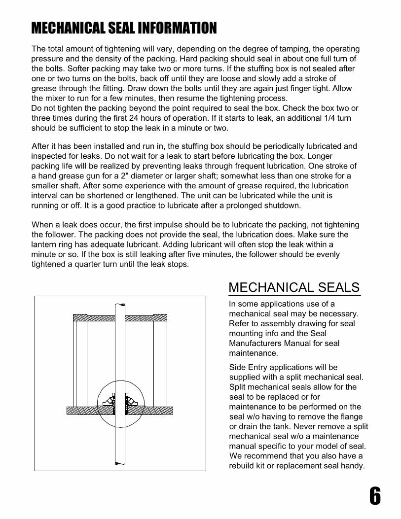
Side Entry applications will besupplied with a split mechanical seal.Split mechanical seals allow for theseal to be replaced or formaintenance to be performed on theseal w/o having to remove the flangeor drain the tank. Never remove a splitmechanical seal w/o a maintenancemanual specific to your model of seal.We recommend that you also have arebuild kit or replacement seal handy.
MECHANICAL SEAL INFORMATIONThe total amount of tightening will vary, depending on the degree of tamping, the operatingpressure and the density of the packing. Hard packing should seal in about one full turn ofthe bolts. Softer packing may take two or more turns. If the stuffing box is not sealed afterone or two turns on the bolts, back off until they are loose and slowly add a stroke ofgrease through the fitting. Draw down the bolts until they are again just finger tight. Allowthe mixer to run for a few minutes, then resume the tightening process.Do not tighten the packing beyond the point required to seal the box. Check the box two orthree times during the first 24 hours of operation. If it starts to leak, an additional 1/4 turnshould be sufficient to stop the leak in a minute or two.
After it has been installed and run in, the stuffing box should be periodically lubricated andinspected for leaks. Do not wait for a leak to start before lubricating the box. Longerpacking life will be realized by preventing leaks through frequent lubrication. One stroke ofa hand grease gun for a 2" diameter or larger shaft; somewhat less than one stroke for asmaller shaft. After some experience with the amount of grease required, the lubricationinterval can be shortened or lengthened. The unit can be lubricated while the unit isrunning or off. It is a good practice to lubricate after a prolonged shutdown.
When a leak does occur, the first impulse should be to lubricate the packing, not tighteningthe follower. The packing does not provide the seal, the lubrication does. Make sure thelantern ring has adequate lubricant. Adding lubricant will often stop the leak within aminute or so. If the box is still leaking after five minutes, the follower should be evenlytightened a quarter turn until the leak stops.
In some applications use of amechanical seal may be necessary.Refer to assembly drawing for sealmounting info and the SealManufacturers Manual for sealmaintenance.
MECHANICAL SEALS
6
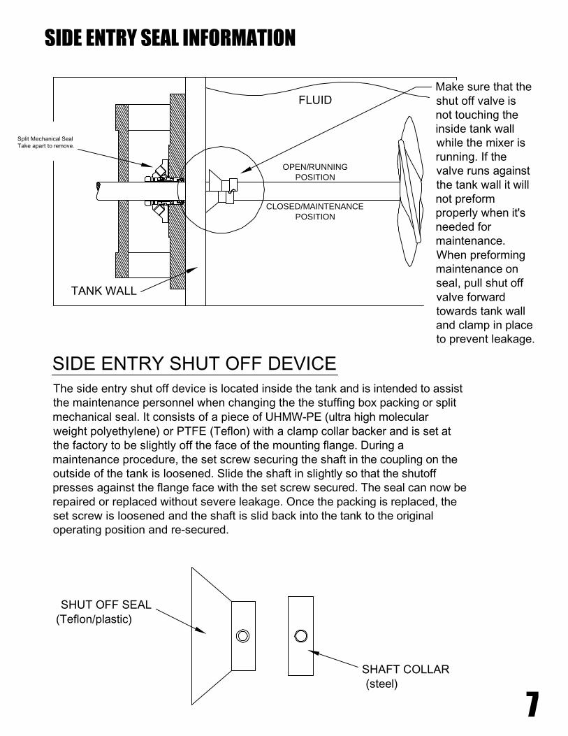
Make sure that theshut off valve isnot touching theinside tank wallwhile the mixer isrunning. If thevalve runs againstthe tank wall it willnot preformproperly when it'sneeded formaintenance.When preformingmaintenance onseal, pull shut offvalve forwardtowards tank walland clamp in placeto prevent leakage.
SIDE ENTRY SEAL INFORMATION
OPEN/RUNNINGPOSITION
CLOSED/MAINTENANCEPOSITION
SIDE ENTRY SHUT OFF DEVICEThe side entry shut off device is located inside the tank and is intended to assistthe maintenance personnel when changing the the stuffing box packing or splitmechanical seal. It consists of a piece of UHMW-PE (ultra high molecularweight polyethylene) or PTFE (Teflon) with a clamp collar backer and is set atthe factory to be slightly off the face of the mounting flange. During amaintenance procedure, the set screw securing the shaft in the coupling on theoutside of the tank is loosened. Slide the shaft in slightly so that the shutoffpresses against the flange face with the set screw secured. The seal can now berepaired or replaced without severe leakage. Once the packing is replaced, theset screw is loosened and the shaft is slid back into the tank to the originaloperating position and re-secured.
SHUT OFF SEAL(Teflon/plastic)
SHAFT COLLAR(steel)
FLUID
TANK WALL
Split Mechanical SealTake apart to remove.
7
8
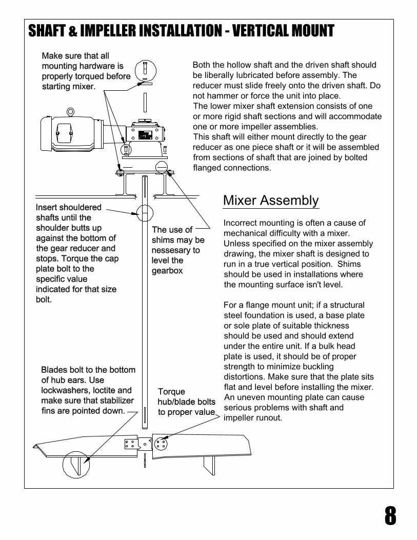
SHAFT & IMPELLER INSTALLATION - VERTICAL MOUNT
Both the hollow shaft and the driven shaft shouldbe liberally lubricated before assembly. Thereducer must slide freely onto the driven shaft. Donot hammer or force the unit into place.The lower mixer shaft extension consists of oneor more rigid shaft sections and will accommodateone or more impeller assemblies.This shaft will either mount directly to the gearreducer as one piece shaft or it will be assembledfrom sections of shaft that are joined by boltedflanged connections.
Incorrect mounting is often a cause ofmechanical difficulty with a mixer.Unless specified on the mixer assemblydrawing, the mixer shaft is designed torun in a true vertical position. Shimsshould be used in installations wherethe mounting surface isn't level.
For a flange mount unit; if a structuralsteel foundation is used, a base plateor sole plate of suitable thicknessshould be used and should extendunder the entire unit. If a bulk headplate is used, it should be of properstrength to minimize bucklingdistortions. Make sure that the plate sitsflat and level before installing the mixer.An uneven mounting plate can causeserious problems with shaft andimpeller runout.
Mixer Assembly
9
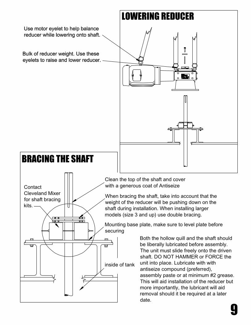
LOWERING REDUCER
Both the hollow quill and the shaft shouldbe liberally lubricated before assembly.The unit must slide freely onto the drivenshaft. DO NOT HAMMER or FORCE theunit into place. Lubricate with withantiseize compound (preferred),assembly paste or at minimum #2 grease.This will aid installation of the reducer butmore importantly, the lubricant will aidremoval should it be required at a laterdate.
inside of tank
Mounting base plate, make sure to level plate beforesecuring
When bracing the shaft, take into account that theweight of the reducer will be pushing down on theshaft during installation. When installing largermodels (size 3 and up) use double bracing.
Clean the top of the shaft and coverwith a generous coat of Antiseize
BRACING THE SHAFT
ContactCleveland Mixerfor shaft bracingkits.
10
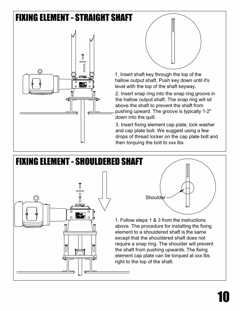
FIXING ELEMENT - STRAIGHT SHAFT
FIXING ELEMENT - SHOULDERED SHAFT
1. Insert shaft key through the top of thehallow output shaft. Push key down until it'slevel with the top of the shaft keyway.
2. Insert snap ring into the snap ring groove inthe hallow output shaft. The snap ring will sitabove the shaft to prevent the shaft frompushing upward. The groove is typically 1-2"down into the quill.
3. Insert fixing element cap plate, lock washerand cap plate bolt. We suggest using a fewdrops of thread locker on the cap plate bolt andthen torquing the bolt to xxx lbs
1. Follow steps 1 & 3 from the instructionsabove. The procedure for installing the fixingelement to a shouldered shaft is the sameexcept that the shouldered shaft does notrequire a snap ring. The shoulder will preventthe shaft from pushing upwards. The fixingelement cap plate can be torqued at xxx lbsright to the top of the shaft.
Shoulder

REDUCER AND MOUNTING PLATE BOLTS
11
MOUNTING
These bolts are also subject to high loads and should be properly torqued to prevent boltstretch and reducer wobble.For situations where the reducer is on the larger side, the shafting is on the longer sideand/or the unit is equipped with large turbines; use additional care to make sure that thebolts are installed and torqued properly.
If torque wrenches are not available, use "turn of the nut method". This method can besummed up in one sentence: Turn the nut 1/2 to 2/3's of a turn past the snug tight position.This applies to any bolt of any size.ALL FASTENERS SHOULD BE CLEAN, RUST FREE AND LIGHTLY OILED.
AXIAL RETENTIONEach drive shaft must be retained in place relative to the gear reducer. Cleveland Mixerrecommends the use of shaft shoulders, locking collars, snap rings or fixing elements toaxially retain the shaft gear reducer position. Most units are designed and come equippedwith these items.
If set screws are used for axial retention, they should be tightened evenly. It is a good ideato use a drop of "Lock-Tite" or some form of thread locker on the set screws before installingthem. This will help in the prevention of set screw back off. Flats or dimples may be used onthe drive shafts to give set screws something to grab onto.
SET SCREWS
SNAP RINGSSnap rings are used to retain the shaft from sliding upward in cases where the shaft doesn'thave a shoulder. The snap ring should be inserted into the grove inside of the hollow outputbore. The snap ring will sit just above the top of the drive shaft. There may be a spacebetween the cap plate and the top of the shaft. Cleveland Mixer suggests the use of a threadlocking adhesive on the cap plate bolt. The cap plate bolt should screw down into the driveshaft at least the same diameter of the bolt, if not all the way to the end of the shaft thread.This bolt should be torqued as in accordance with the torque chart in this manual.
IMPELLERS & SHAFTS
12
BOLT SIZEALL MATERIALS
FOOT POUNDS NUMBER1/2 - 13 50 68
5/8 - 11 90 122
3/4 - 10 160 217
7/8 - 9 140 190
1 - 8 220 2981 - 1/8 - 7 300 407
1 - 1/4 - 7 420 570
1 - 3/8 - 6 556 754
10037401 - 1/2 - 6
1 - 3/4 - 5 825 1118
2 - 4 - 1/2 1125 1525
2 - 1/4 - 4 - 1/2 1725 2338
2 - 1/2 - 4 2300 3117
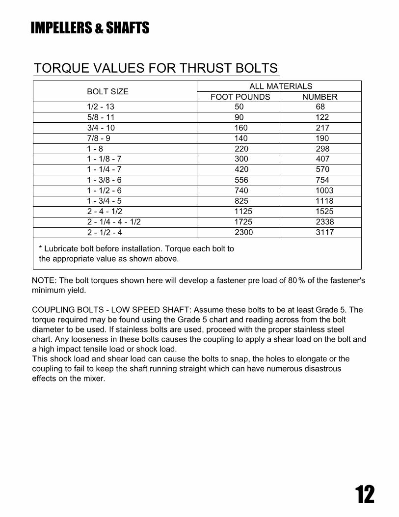
* Lubricate bolt before installation. Torque each bolt tothe appropriate value as shown above.
NOTE: The bolt torques shown here will develop a fastener pre load of 80% of the fastener'sminimum yield.
COUPLING BOLTS - LOW SPEED SHAFT: Assume these bolts to be at least Grade 5. Thetorque required may be found using the Grade 5 chart and reading across from the boltdiameter to be used. If stainless bolts are used, proceed with the proper stainless steelchart. Any looseness in these bolts causes the coupling to apply a shear load on the bolt anda high impact tensile load or shock load.This shock load and shear load can cause the bolts to snap, the holes to elongate or thecoupling to fail to keep the shaft running straight which can have numerous disastrouseffects on the mixer.
TORQUE VALUES FOR THRUST BOLTS
1 - 1/2 - 6
1 - 3/8 - 6
1 - 1/4 - 7
1 - 1/8 - 71 - 8
7/8 - 9
3/4 - 10
5/8 - 11
1/2 - 13
NmFT-LB
BOLTSIZE
CARBON STEEL
13
IMPELLERS & SHAFTS
3/8 - 16
9/16 - 12
Grade 2
FT-LB Nm
Grade 5
FOOT-LBS NUMBER
Stainless Steel, Alloy 20,Monel, Hastelloy C
15 20 23 30 2115
38 51 56 77 37 50
7254112836850
68 92 113 152 74 101
178131271200163120
105 143 296 401 212 287
165 224 443 601 318 432
225 305 596 808 450 610
315 428 840 1139 636 862
417 566 1003 1495 834 1130
555 752 1463 1983 1470 1500
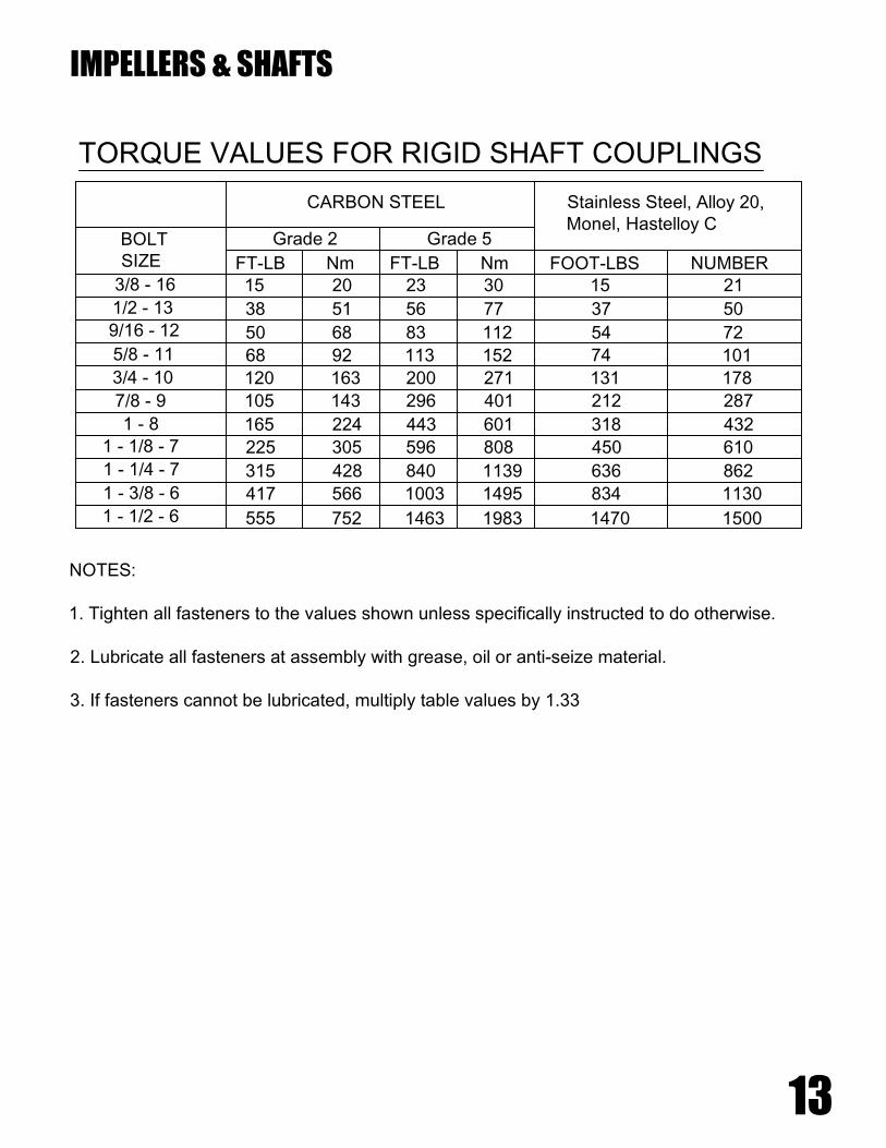
NOTES:
1. Tighten all fasteners to the values shown unless specifically instructed to do otherwise.
2. Lubricate all fasteners at assembly with grease, oil or anti-seize material.
3. If fasteners cannot be lubricated, multiply table values by 1.33
TORQUE VALUES FOR RIGID SHAFT COUPLINGS

3rd blade/hub armnot pictured
3rd blade/hub armnot pictured
NOTE: The extensionshaft and other machinedparts with closetolerances have beenstraightened and balancedto several thousandths ofan inch. Please be carefulwhen handling andinstalling this equipment.NOTE: Keys have drillpoints on one side for setscrew alignment.To install any impeller,simply slide the impellerhub ( top end of hub willbe marked top) onto theshaft above the keyway.Slide the hub back downover the key until the hubis positioned with the setscrew hole over the drillpoint on the key. Firmlytighten the hub set screwinto the key.
Both the hollow shaft and thedriven shaft should beliberally lubricated beforeassembly. The reducer mustslide freely onto the drivenshaft. Do not hammer or forcethe unit into place.The lower mixer shaftextension consists of one ormore rigid shaft sections andwill accommodate one ormore impeller assemblies.This shaft will either mountdirectly to the gear reducer asone piece shaft or it will beassembled from sections ofshaft that are joined by boltedflanged connections.
MULTIPLE IMPELLER INSTALLATION
SINGLE IMPELLER INSTALLATION
IMPELLERS & SHAFTS
14
Blades bolt up to thebottom of the hubears.Stabilizer fins pointdown.Larger diameterblades go on thebottom and decreasein width as they goup.

IMPELLERS & SHAFTS
15
Now that the impeller hub is on the shaft, firmly bolt the impeller hardware (blades, discs,stabilizers) into place. All in-tank fastening involving the couplings and turbine hubs do notuse lockwashers. All in-tank fastenings should be rechecked for tightness after 1500 hoursof operation. It is also recommended to check at scheduled shut down periods. All shaft andimpeller bolts should be torqued to the values shown in the torque value table in this manual.
The upper shaft or shaft section, if it is a multi-piece shaft assembly, will have either awelded coupling or a removable tapered bore coupling that will mate with the low speedshaft on the reducer.The welded coupling is used on upper shaft sections for open tank mixers that do not haveany impellers mounted to it that would need to be removed. With a taper bore coupling, theupper shaft is assembled to the taper coupling and held in place by the internal cap platebolted to the top of the shaft.The rigid coupling is the welded flange type that requires no installation and would normallybe found attached to the upper shaft assembly, either in or out of the process. There may beseveral of these type connections between shaft sections in the assembly.
TAPER BORE COUPLING RIGID COUPLING
IMPELLER INSTALLATION
1. XTF-3R Impeller blades and hubs are shipped disassembled.2. Slide the hub to the desired location over the key (the hub should be marked with "TOP"make sure that side is up). Tighten the set screw over the key. Impellers over 50 inches indiameter are provided with Gib keys. Lower the hub slowly until it rests on the Gib, thentighten the set screw.3. Assemble the blades to the underside of the hub using four hex head cap screws and nutsper blade. Torque all bolts to the required specifications.4. Retighten all bolted connections using proper torque settings before starting the mixer.
16
IMPELLERS & SHAFTS
STEADY BEARING
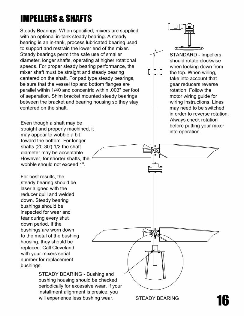
Steady Bearings: When specified, mixers are suppliedwith an optional in-tank steady bearing. A steadybearing is an in-tank, process lubricated bearing usedto support and restrain the lower end of the mixer.Steady bearings permit the safe use of smallerdiameter, longer shafts, operating at higher rotationalspeeds. For proper steady bearing performance, themixer shaft must be straight and steady bearingcentered on the shaft. For pad type steady bearings,be sure that the vessel top and bottom flanges areparallel within 1/40 and concentric within .003" per footof separation. Shim bracket mounted steady bearingsbetween the bracket and bearing housing so they staycentered on the shaft.
Even though a shaft may bestraight and properly machined, itmay appear to wobble a bittoward the bottom. For longershafts (20-30') 1/2 the shaftdiameter may be acceptable.However, for shorter shafts, thewobble should not exceed 1".
For best results, thesteady bearing should belaser aligned with thereducer quill and weldeddown. Steady bearingbushings should beinspected for wear andtear during every shutdown period. If thebushings are worn downto the metal of the bushinghousing, they should bereplaced. Call Clevelandwith your mixers serialnumber for replacementbushings.
STANDARD - Impellersshould rotate clockwisewhen looking down fromthe top. When wiring,take into account thatgear reducers reverserotation. Follow themotor wiring guide forwiring instructions. Linesmay need to be switchedin order to reverse rotation.Always check rotationbefore putting your mixerinto operation.
STEADY BEARING - Bushing andbushing housing should be checkedperiodically for excessive wear. If yourinstallment alignment is presice, youwill experience less bushing wear.
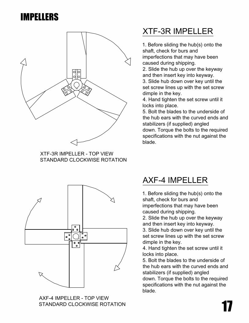
1. Before sliding the hub(s) onto theshaft, check for burs andimperfections that may have beencaused during shipping.2. Slide the hub up over the keywayand then insert key into keyway.3. Slide hub down over key until theset screw lines up with the set screwdimple in the key.4. Hand tighten the set screw until itlocks into place.5. Bolt the blades to the underside ofthe hub ears with the curved ends andstabilizers (if supplied) angleddown. Torque the bolts to the requiredspecifications with the nut against theblade.
AXF-4 IMPELLER - TOP VIEWSTANDARD CLOCKWISE ROTATION
XTF-3R IMPELLER - TOP VIEWSTANDARD CLOCKWISE ROTATION
AXF-4 IMPELLER
XTF-3R IMPELLER
1. Before sliding the hub(s) onto theshaft, check for burs andimperfections that may have beencaused during shipping.2. Slide the hub up over the keywayand then insert key into keyway.3. Slide hub down over key until theset screw lines up with the set screwdimple in the key.4. Hand tighten the set screw until itlocks into place.5. Bolt the blades to the underside ofthe hub ears with the curved ends andstabilizers (if supplied) angleddown. Torque the bolts to the requiredspecifications with the nut against theblade.
IMPELLERS
17
18
Oil Level
Oil Input
Drain PlugGrease Fittings
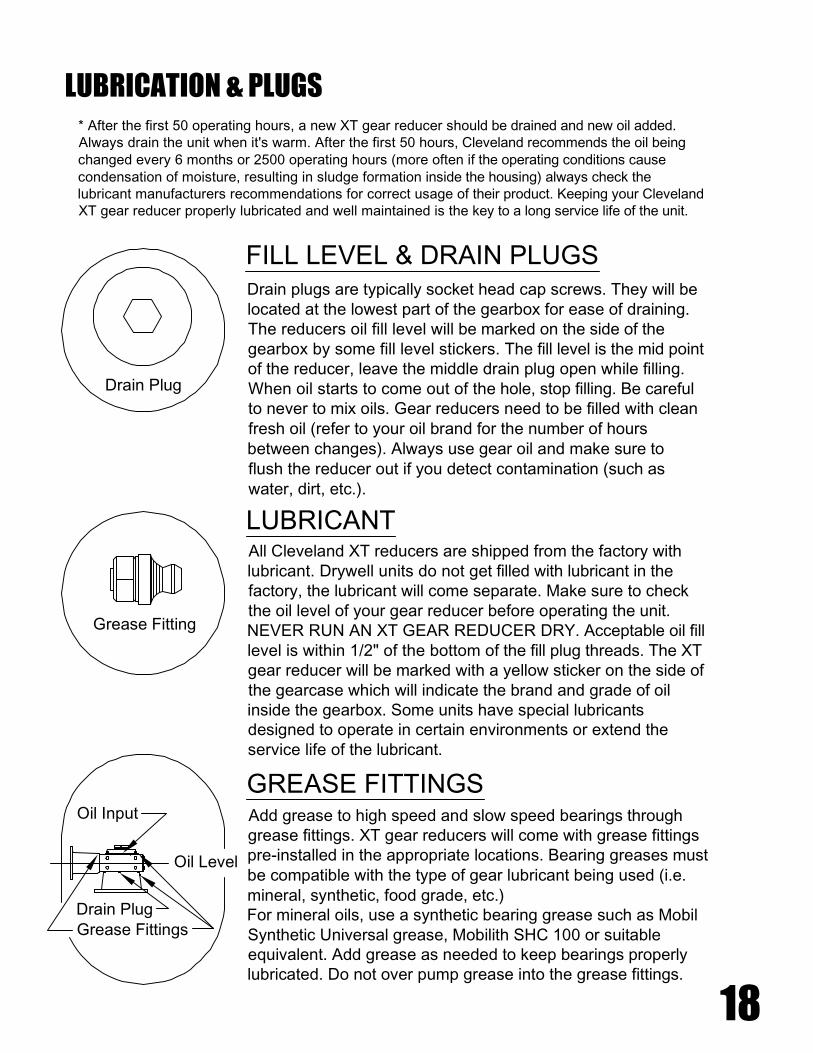
GREASE FITTINGSAdd grease to high speed and slow speed bearings throughgrease fittings. XT gear reducers will come with grease fittingspre-installed in the appropriate locations. Bearing greases mustbe compatible with the type of gear lubricant being used (i.e.mineral, synthetic, food grade, etc.)For mineral oils, use a synthetic bearing grease such as MobilSynthetic Universal grease, Mobilith SHC 100 or suitableequivalent. Add grease as needed to keep bearings properlylubricated. Do not over pump grease into the grease fittings.
All Cleveland XT reducers are shipped from the factory withlubricant. Drywell units do not get filled with lubricant in thefactory, the lubricant will come separate. Make sure to checkthe oil level of your gear reducer before operating the unit.NEVER RUN AN XT GEAR REDUCER DRY. Acceptable oil filllevel is within 1/2" of the bottom of the fill plug threads. The XTgear reducer will be marked with a yellow sticker on the side ofthe gearcase which will indicate the brand and grade of oilinside the gearbox. Some units have special lubricantsdesigned to operate in certain environments or extend theservice life of the lubricant.
LUBRICANT
Grease Fitting
Drain Plug
FILL LEVEL & DRAIN PLUGSDrain plugs are typically socket head cap screws. They will belocated at the lowest part of the gearbox for ease of draining.The reducers oil fill level will be marked on the side of thegearbox by some fill level stickers. The fill level is the mid pointof the reducer, leave the middle drain plug open while filling.When oil starts to come out of the hole, stop filling. Be carefulto never to mix oils. Gear reducers need to be filled with cleanfresh oil (refer to your oil brand for the number of hoursbetween changes). Always use gear oil and make sure toflush the reducer out if you detect contamination (such aswater, dirt, etc.).
LUBRICATION & PLUGS* After the first 50 operating hours, a new XT gear reducer should be drained and new oil added.Always drain the unit when it's warm. After the first 50 hours, Cleveland recommends the oil beingchanged every 6 months or 2500 operating hours (more often if the operating conditions causecondensation of moisture, resulting in sludge formation inside the housing) always check thelubricant manufacturers recommendations for correct usage of their product. Keeping your ClevelandXT gear reducer properly lubricated and well maintained is the key to a long service life of the unit.

19
Cleveland Eastern Mixers XT Gear Reducer:* This unit was lubricated with MOBIL GLYGOYLE 460 gear lubricant. The PAG based stocksused in MOBIL GLYGOYLE 460 do not chemically react with mineral or PAO lubricants and arenot miscible. DO NOT MIX LUBRICANTS . Use only MOBIL GLYGOYLE 460 in this reducer.
* The oil level for all top mounted, drywell units is at the halfway mark of the gearcase. Fornon-drywell side mounted units - CONSULT O&M manual for lubricating instructions.
* OIL CHANGE FREQUENCY - Every 6 months or 2500 operating hours. Consult factory incases of extreme operating conditions.
* GREASE INPUT and OUTPUT BEARINGS - add grease to bearings through grease fittings.Grease fittings are provided for bearings not adequately lubricated by the splash system.Pressure lubricate with a short fiber grease having a work penetration of 310 to 340 at 77° andan ASTM point of 350°F minimum.
* Consult O&M manual for venting instructions. All XT model gear reducers require a ventilator.
EMI Inc. 4 Heritage Park RD. (860)-669-1199Clinton, CT 06413 www.emimixers.com
ID / LUBRICATION TAGS
IDENTIFICATION TAG
LUBRICATION INFO
This sticker indicates that you have Clevelands standard issue XT lubricant inside of your XTgear reducer. Cleveland recommends continued use of this product and that you follow all ofthe lubricant manufacturers recommendations as far as frequency of changes, ambienttemperature and operating environment.
This tag will be glued to the side of the gear case on your XTgear reducer. When calling for parts, service or for technicalhelp; please relay the serial number and model number off ofthis tag to Cleveland.
20
LUBRICATING INFORMATION FOR XT
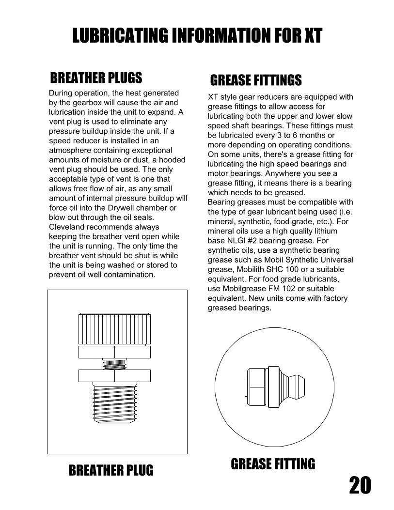
XT style gear reducers are equipped withgrease fittings to allow access forlubricating both the upper and lower slowspeed shaft bearings. These fittings mustbe lubricated every 3 to 6 months ormore depending on operating conditions.On some units, there's a grease fitting forlubricating the high speed bearings andmotor bearings. Anywhere you see agrease fitting, it means there is a bearingwhich needs to be greased.Bearing greases must be compatible withthe type of gear lubricant being used (i.e.mineral, synthetic, food grade, etc.). Formineral oils use a high quality lithiumbase NLGI #2 bearing grease. Forsynthetic oils, use a synthetic bearinggrease such as Mobil Synthetic Universalgrease, Mobilith SHC 100 or a suitableequivalent. For food grade lubricants,use Mobilgrease FM 102 or suitableequivalent. New units come with factorygreased bearings.
During operation, the heat generatedby the gearbox will cause the air andlubrication inside the unit to expand. Avent plug is used to eliminate anypressure buildup inside the unit. If aspeed reducer is installed in anatmosphere containing exceptionalamounts of moisture or dust, a hoodedvent plug should be used. The onlyacceptable type of vent is one thatallows free flow of air, as any smallamount of internal pressure buildup willforce oil into the Drywell chamber orblow out through the oil seals.Cleveland recommends alwayskeeping the breather vent open whilethe unit is running. The only time thebreather vent should be shut is whilethe unit is being washed or stored toprevent oil well contamination.
BREATHER PLUGS GREASE FITTINGS
LUBRICATING INFORMATION FOR XT
BREATHER PLUG GREASE FITTING

-40 to 230°F ( -40 - 110°C)
OPTIONAL BEARING GREASES
AMBIENT TEMPERATURE FORMULATION MANUFACTURER OIL BRAND NAME
-40 to 230°F ( -40 - 110°C) SYNTHETIC
FOOD GRADE OIL - SYNTHETIC
SHELL
LUBRIPLATE
AEROSHELL 6
SFL1
STANDARD BEARING GREASE
MINERAL-20°F TO +140°F ( -30 TO 60°C)
FORMULATIONAMBIENT TEMPERATURE
ALBIDA LC
MOBILUX SHC 007
MOBILUX EP023
MAGNAPLATE 85W 140FG
FM ISO 220
SHELL
MOBILE
MOBILE
OILJAX
CHEVRON
FLUID GREASE - SYNTHETIC
FLUID GREASE - SYNTHETIC
FLUID GREASE
FOOD GRADE OIL - SYNTHETIC
FOOD GRADE OIL - SYNTHETIC
-30°F TO +140°F ( -35 TO 60°C)
-30°F TO +140°F ( -35 TO 60°C)
5°F TO +125°F ( -20 TO 50°C)
20°F TO +104°F ( -5 TO 40°C)
20°F TO +104°F ( -5 TO 40°C)
OIL BRAND NAMEMANUFACTURERFORMULATIONAMBIENT TEMPERATURE
SPECIAL PURPOSE LUBRICANTS
* PAO - Poly Alpha Olefin
N/AN/A N/AN/AKluber-SummitHySyn FG-32
Mobil SHC624
N/AN/AN/AN/AN/AN/A
Mobilgear626
Omala68
2EP Kluberoil GEM1-68
Energol GR-XP68
Tribol1100/68
N/AN/AN/AIsolube EP68
N/AMobil SHC626
Mobil SHC629
Omala 150HD
Isolube EP150
Klubersynth EG4-150
N/A N/A
Tribol1100/100
Energol GR-XP100
Kluberoil GEM1-150
4EPOmala100
Mobilgear629
Mobilgear630
Omala220
5EP Kluberoil GEM1-220
Energol GR-XP220
Tribol1100/220
Tribol1510/220
N/AKlubersynth EG4-220
Isolube EP220
Omala 220HD
Mobil SHC630
Mobil SHC632
Omala 320HD
Isolube EP460
Klubersynth EG4-320
N/A Tribol1510/320
Tribol1100/320
Energol GR-XP320
Kluberoil GEM1-320
6EPOmala320
Mobilgear632
Mobil SHC634
Omala 460HD
Isolube EP460
Klubersynth EG4-460
N/A Tribol1510/460
Tribol1100/460
Energol GR-XP460
Kluberoil GEM1-460
7EPOmala 460Mobilgear634
TRIBOLBPKLUBERCASTROLSHELLMOBIL
40°F TO +50°F-40°C TO +10°C
-
35°F TO +50°F
-35°C TO +10°C
-15°C TO +25°C
+5°F TO +77°F
+5°F TO +77°F
-15°C TO +25°C
-35°C TO +10°C
35°F TO +50°F
31°F TO +176°F
-35°C TO +80°C
-5°C TO +40°C
+20°F TO +104°F
32°F TO +86°F
0°C TO +30°C
-35°C TO +80°C
31°F TO +176°F
22°F TO +176°F
-30°C TO +80°C
20°C TO +50°C
68°F TO +122°F
-
SYNTHETIC PAO
SYNTHETIC PAO
CONVENTIONALMINERAL
CONVENTIONALMINERAL
SYNTHETIC PAO
SYNTHETIC PAO
CONVENTIONALMINERAL
CONVENTIONALMINERAL
SYNTHETIC PAO
SYNTHETIC PAO
CONVENTIONALMINERAL
VG 32
VG 68
VG 150 &VG 100
VG 220
VG 320
VG 460
SERVICE TEMP-ERATURE RANGE
FORMULATIONVISCOSITYISO NLGI
LUBRICANT CHARTS* STANDARD XT GEAR REDUCERS COME WITH MOBIL GLYGOYLE 460 SYNTHETIC GEAR LUBRICANT
( UNLESS OTHERWISE NOTED) . CLEVELAND STRONGLY RECOMMENDS CONTINUED USE OF THIS OIL
21
HIGH SPEED COUPLING
SIDE ENTRY SUPPORTS
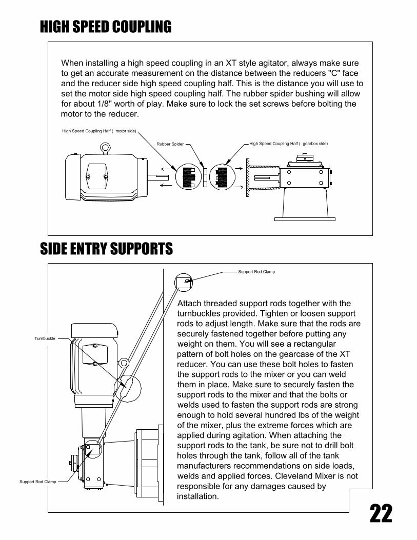
Attach threaded support rods together with theturnbuckles provided. Tighten or loosen supportrods to adjust length. Make sure that the rods aresecurely fastened together before putting anyweight on them. You will see a rectangularpattern of bolt holes on the gearcase of the XTreducer. You can use these bolt holes to fastenthe support rods to the mixer or you can weldthem in place. Make sure to securely fasten thesupport rods to the mixer and that the bolts orwelds used to fasten the support rods are strongenough to hold several hundred lbs of the weightof the mixer, plus the extreme forces which areapplied during agitation. When attaching thesupport rods to the tank, be sure not to drill boltholes through the tank, follow all of the tankmanufacturers recommendations on side loads,welds and applied forces. Cleveland Mixer is notresponsible for any damages caused byinstallation.
Support Rod Clamp
Support Rod Clamp
Turnbuckle
When installing a high speed coupling in an XT style agitator, always make sureto get an accurate measurement on the distance between the reducers "C" faceand the reducer side high speed coupling half. This is the distance you will use toset the motor side high speed coupling half. The rubber spider bushing will allowfor about 1/8" worth of play. Make sure to lock the set screws before bolting themotor to the reducer.
High Speed Coupling Half ( gearbox side)
High Speed Coupling Half ( motor side)
Rubber Spider
22

3. Cleveland warranty applies to onlyitems furnished by Cleveland Mixer. Allother equipment & designs are theresponsibility of others Cleveland mixerdoes not warrant, guarantee or assumeany responsibility for the design orconstruction of the mounting structure forthe mixer.
1. Beam designation symbols standardM - Misc. (wide flange) shapes (M)W - Wide flange shapes (WF)
2. Design loads exceed actual loads bya factor consistentwith construction codes. If therecommended beams are to carryadditional loads to the mixer, largerbeams may be required.
CLOSE OFF BEAMSAT BOTH ENDS
LATERAL BRACING - SAMESIZE AS MAIN BEAMS
MIXER MOUNTING HOLES
SUPPORT BEAM RECOMMENDATIONS
23
Support beams should be bridgedover the tank and be supported by asolid surface. Tanks often vibrate, ifthe support bridging is only supportedby the tank then the mixer will not besupported by the solid surface itneeds in order to operate the way itwas designed to. Even if your tank ismade from steel, when the weight ofliquid inside of the tank starts moving,the tank can vibrate, pulsate, sway,etc. That can create run out andmovement that the shaft, impellersand gear reducer were not designedto tolerate.
TANK
BRIDGING
SUPPORT BEAMS SHOULD BRIDGE TANK AND COME UPFROM THE GROUND OR FLOOR
MOUNTING PLATEw/ CENTER HOLE FOR SHAFTING
USE MOUNTING BOLTSAND WELDS TO HOLDMOUNTING PLATES INPLACE. THE MORERIDGED YOUR MOUNTINGPLATE THE BETTER YOURMIXER WILL PERFORM.

Flush the unit immediately with warm oil (100°F) of the same type and viscosity used inthe original fill (XT gearboxes are marked with the oil used to fill them on the side of thegearcase).
After the first month: Start the unit. When the sump oil reaches normal operatingtemperature, shut the drive down and immediately drain the oil. The magnetic plug shouldbe cleaned at this time.
PREVENTATIVE MAINTENANCEAfter the first week after startup / restart: Check all external fasteners and plugs fortightness.Gears and internal bearings have been factory set and require no adjustments. Drivenshaft bearings require no maintenance other than periodic regreasing.
LONG TERM SHUTDOWN - If the unit is to be deactivated or stored for more than fourmonths after any period of operation:
1. Indoor dry storage is recommended for all inactive units. Deactivated units storedoutdoors should be protected from the weather. It is most important to keep the unit dryand in a temperature controlled area.
2. Drain the oil from the unit and spray the inside of the gearcase with a long term storagelubricant such as "Motorstor" or a suitable vapor phase rust inhibitor at the rate of oneounce per cubic foot. Make sure to mark the gearbox appropriately so that the storagelubricant is drained and the gearcase is refilled with the proper lubricant before restarting.
3. Mixer shafts should be removed and coated with Cosmoline or suitable preservative( even stainless steel shafts should be coated where they come into contact with steel orbanding straps) Make sure the shafts are properly supported to prevent bending. It isgood to rotate the shafts periodically to keep them from settling in one position which cancause them to bend. When storing carbon steel parts outdoors, apply suitable grease orrust preventative to all parts. Turbine parts should also be coated with preservative,especially the bore of the turbine hub.
4. Motors should be stored in a cool, dry environment: the motor shaft should be rotatedonce each month.
5. Inspect stored or inactive units at 90 day intervals. Re-spray with rust preventative oradd rust inhibitor at least once every 6 months or as required by rust preventativemanufacturer.
SHORT TERM SHUTDOWN - Units may be deactivated and left on line for up to fourmonths without special precautions.
DEACTIVATION & STORAGE
DEACTIVATION
24
STANDARD OIL - INDICATED ON THE SIDE OF THE REDUCER.* DO NOT MIX OILS. ALWAYS DRAIN UNIT COMPLETELY BEFOREUSING A NEW GRADE OR BRAND OF OIL. MIXING MINERAL OIL ANDSYNTHETIC OIL IN THE SAME WELL MAY CAUSE PERMANENTDAMAGE TO GEAR REDUCER.
Cleveland Mixer supplies XT reducers with oil from the factory. Consult the stickeradjacent to the fill plug to determine the type of lubricant installed at the factory. Standardlubricant is GLYGOYLE 460 gear lubricant.
OPERATION & MAINTENANCE CHECKLIST
1. Operate the equipment as it was intended to be operated.2. Do not overload3. Run at correct speed4. Maintain lubricant in good condition and at proper level.5. Apply proper maintenance to attached equipment at prescribed intervals recommendedby Cleveland Mixer.6. Perform periodic maintenance of the gear drive as recommended by Cleveland Mixer.
Mineral lubricant should be changed every 10,000 service hours or after two years ofservice. For synthetic oils, the lube should be changed every 20,000 service hours or afterfour years. In cases of extreme operating conditions (e.g. high humidity, aggressiveenvironment or large temperature variations) shorter intervals between changes arerecommended.
NOTE: If the oil level has risen since the previous check, have the oil analyzed for watercontent. Moisture in the oil may indicate seal leakage or condensation. Drain the oil,correct the defect and refill the unit with fresh oil.
Close the drain and refill the unit to the correct level with fresh oil. Periodically check oillevel and condition with unit stopped. Be sure that oil is at normal operating temperature.Add oil if needed but be careful NOT TO OVERFILL.
PREVENTATIVE MAINTENANCE CONTINUEDPour or pump oil equivalent in volume to 25 % of the original fill through the unit, ifnecessary repeat the procedure until clean oil appears at the drain.
DEACTIVATION & STORAGE
25
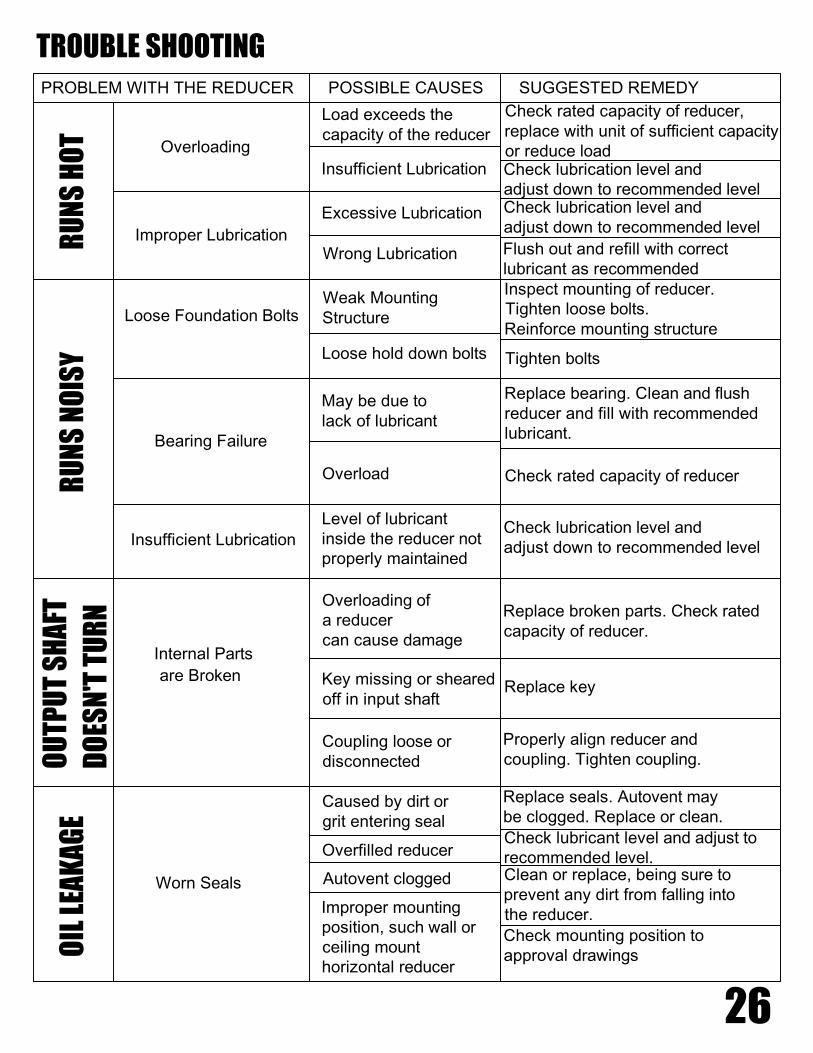
Check mounting position toapproval drawings
Clean or replace, being sure toprevent any dirt from falling intothe reducer.
Check lubricant level and adjust torecommended level.
Replace seals. Autovent maybe clogged. Replace or clean.
Properly align reducer andcoupling. Tighten coupling.
Replace key
Replace broken parts. Check ratedcapacity of reducer.
Check lubrication level andadjust down to recommended level
Check rated capacity of reducer
Replace bearing. Clean and flushreducer and fill with recommendedlubricant.
Tighten bolts
Inspect mounting of reducer.Tighten loose bolts.Reinforce mounting structure
Flush out and refill with correctlubricant as recommended
Check lubrication level andadjust down to recommended level
Check lubrication level andadjust down to recommended level
Check rated capacity of reducer,replace with unit of sufficient capacityor reduce load
Improper mountingposition, such wall orceiling mounthorizontal reducer
Autovent clogged
Overfilled reducer
Caused by dirt orgrit entering seal
Coupling loose ordisconnected
Key missing or shearedoff in input shaft
Overloading ofa reducercan cause damage
Level of lubricantinside the reducer notproperly maintained
May be due tolack of lubricant
Overload
Loose hold down bolts
Weak MountingStructure
Wrong Lubrication
Excessive Lubrication
Insufficient Lubrication
Load exceeds thecapacity of the reducer
Worn Seals
are Broken
Internal Parts
Insufficient Lubrication
Bearing Failure
Loose Foundation Bolts
Improper Lubrication
Overloading
RU
NS
HO
TR
UN
SN
OIS
YO
UTP
UT
SH
AFT
DO
ESN
'TTU
RN
OIL
LEA
KA
GE
TROUBLE SHOOTINGPROBLEM WITH THE REDUCER POSSIBLE CAUSES SUGGESTED REMEDY
26

XT PARTS BREAKDOWN 1(This is a general purpose drawing. Consult factory for specifications)
BELL HOUSING ( SIZED TO MATCH MOTOR FRAME)
MOUNTING BASE ( NEMA)
GEAR HOUSINGOUTPUT SHAFT
MOUNTING HARDWARE
CAP PLATE W/ BOLT AND LOCKWASHER
OIL FILL LINE ( center)
* UNITS WITH AN INTEGRAL DRYWELL SHOULDBE KEPT UPRIGHT AND NOT BE TIPPED ON THEIRSIDES. DRYWELL UNITS SHOULD ONLY BE USED ASTOP MOUNTED UPRIGHT MIXERS. SIDE ENTRYMIXERS WILL NOT BE SUPPLIED WITH A DRYWELL.
27
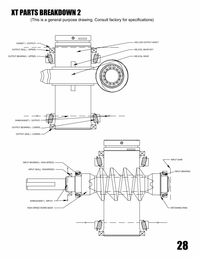
XT PARTS BREAKDOWN 2(This is a general purpose drawing. Consult factory for specifications)
OUTPUT SEAL ( UPPER)
OUTPUT BEARING ( UPPER)
OUTPUT SEAL ( LOWER)
OUTPUT BEARING ( LOWER)
SHIM/GASKET ( OUTPUT)
HELICAL GEAR
HELICAL GEAR KEY
HOLLOW OUTPUT SHAFTGASKET ( OUTPUT)
SHIM/GASKET ( INPUT)
INPUT BEARING ( HIGH SPEED)
INPUT SEAL( HIGHSPEED)
HIGH SPEED WORM GEAR RETAINING RING
INPUT BEARING
INPUT SHIM
28

NOTESDATES
SERVICE RECORDS
29