t hollobolt
TRANSCRIPT

7/26/2019 T HolloBolt
http://slidepdf.com/reader/full/t-hollobolt 1/5
Type HB - Hollo-Bolt
The Lindapter Hollo-Bolt is a patented method of securing to square, rectangular or circular
hollow section steel, or to conventional steelwork where access is available from one side
only. warded
the !esign "ouncil#s $illennium %roducts status for innovation in connecting to hollow section,
the
Hollo-Bolt also has third party endorsements from "orus and the &'#s (teel "onstruction
)nstitute.
The Hollo-Bolt offers a tremendous reduction in installation time and costs over traditional
methods,
as well as giving the specifier absolute confidence through guaranteed loads with a built in
factor
of safety. *or aggresive environments, the Hollo-Bolt comes with +( protection as
standard
and is available in stainless steel if the application demands.
1

7/26/2019 T HolloBolt
http://slidepdf.com/reader/full/t-hollobolt 2/5
M16 and M20 sizes feature a collapse mechanism to maximise clamping force
and enable us to use as a primary moment connection
Typical Hollo-Bolt applications include the connection or suspension of
/ %rimary (teelwork / *ire %rotection (ystems
/ (econdary (teelwork / 0lectrical 0quipment
/ $echanical Handling 0quipment / "ladding
/ Lifting 1ear / Blast 2alling
/ 2all Ties / H3" 0quipment
Head !ariations
variety of finishes and colours are available.
Countersunk Button Head Security Socket Head Cap Screw Hexagonal Head
Stainless Steel Hollo-Bolt
2

7/26/2019 T HolloBolt
http://slidepdf.com/reader/full/t-hollobolt 3/5
4 (afe 2orking Loads for the Hollo-Bolt are dependent upon the yield strength of the hollow
section steel particularly with some of the lighter sections. (afe working loads shown above
have been determined through testing in material with minimum yield strength of 56 78mm5.
&se of steel with lower yield strength will result in lower safe working loads. The highest
tensile
figure given for each bolt si9e is the safe working load of the Hollo-Bolt itself. ny lower figures
against a particular si9e show that the mode of failure in that case is the hollow section steel,
rather than the Hollo-Bolt.
442hilst the minimum fi:ing thickness for $;<8$5 is =mm, it is important that the outer ply is
at least =mm to ma:imise shear capabilities. 2here the outer ply is below =mm thickness,
spacer washers should be used beneath the collar to increase to =mm.
444*or further >H( (ection details not listed, please contact our technical department.
The tables abo"e state the #$% &ith a '(1 factor of safety and should be used for
secondary applications) for primary design please consult the guide *oints in
#teel +onstruction - #imple +onnections
The guide provides design guidence for the use of Hollo-Bolt and gives essential
information for structural steelwork connections for use in buildings designed by the?(imple $ethod? i.e.
braced frames where connections carry mainly shear and a:ial loads only.
To obtain further details on the (imple "onnections guide please contact The (teel
"onstruction )nstitute on Tel @AA C ;DAA <5D DA or *a: @AA C ;DAA <55 EAA
%ublished by (")8B"( "onnections 1roup.
%ublication 7umber %5;5 )(B7 ; =EA5 65 E
3

7/26/2019 T HolloBolt
http://slidepdf.com/reader/full/t-hollobolt 4/5
,nstalling the Hollo-Bolt
%erhaps Hollo-Bolt#s greatest advantage is the ease with which the product can be
installed.
!etailed below are the three simple installation stages
#tep 1
!rill holes in required position see hole
preparation table below for recommended
hole si9eC. Fffer up the Hollo-Bolt and fi:ture
to the steelwork the e:ample pictured on the
right shows steel angleC. )nsert product
through both fi:ture and steelwork, cone end
first.
#tep 2
1rip the Hollo-Bolt collar with an open ended
spanner. &sing a torque wrench, tighten the
central bolt to the recommended torque given
in the table above.
4
7/26/2019 T HolloBolt
http://slidepdf.com/reader/full/t-hollobolt 5/5
#tep
The Hollo-Bolt cone is drawn up into the
body, spreading the product legs and
providing a secure fi:ing.
2hen installing in an inverted position,
ensure that the Hollo-Bolt collar is heldfirmly against the fi:ture.
*or ease of installation please use pneumatic tools on primary structural connections.
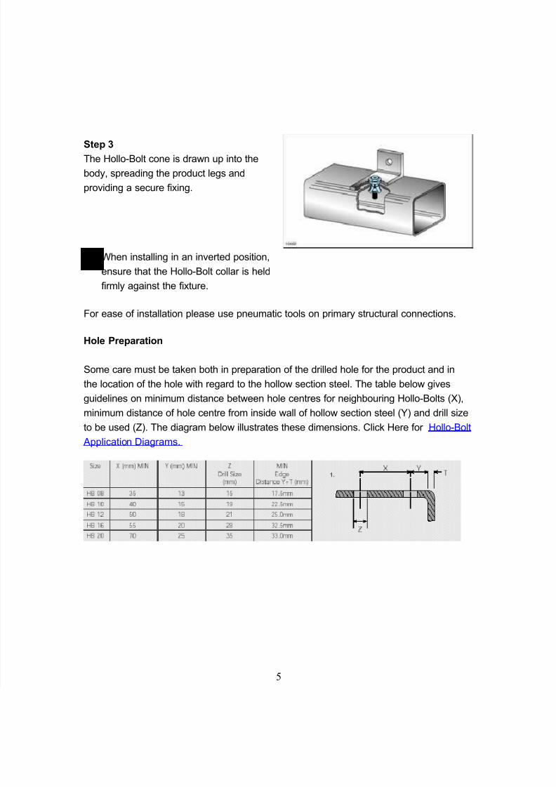
Hole .reparation
(ome care must be taken both in preparation of the drilled hole for the product and in
the location of the hole with regard to the hollow section steel. The table below gives
guidelines on minimum distance between hole centres for neighbouring Hollo-Bolts GC,
minimum distance of hole centre from inside wall of hollow section steel C and drill si9eto be used IC. The diagram below illustrates these dimensions. "lick Here for Hollo-Bolt
pplication !iagrams.
5
/B