t echnical report i to relate a more accurate accessment of the material's ... stress analysis...
TRANSCRIPT
AII
T ECHNICAL REPORTI
NO. 12763
PROPERTIES FOR ALUMINA-ALUMINUM
METAL MATRIX COMPOSITES
SEPTEMBER 1983
T. N. Kler & D. T. Ostberg
US Army Tank-Automotive Command
ATTN: DRSTA-RCK-Mby Warren, MI 48090
Ii
Approved for Public Release:Distribution Unlimited
U.S. ARMY TANK-AUTOMOTIVE COMMANDRESEARCH AND DEVELOPMENT CENTERWarren, Michigan 48090 4809OglKO0-
NOTICES
This report is not to be construed as an official Department of theArmy position.
Mention of any trade names or manufacturers in this report shall not beconstrued as an official indorsement or approval of such products orcompanies by the US Government.
Destroy this report when it is no longer needed. Do not return it tothe originator.
UnclassifiedSECURITY CLASSIFICATION OF THIS PAGE (*7ien Data Entered)
REPORT DOCUMENTATION PAGE READ INSTRUCTIONSBEFORE COMPLETING FORM
1. REPORT NUMBER 2. GOVT ACCESSION NO. 3. RECIPIENT'S CATALOG NUMBER
12763
4. TITLE (nd Subtitle) 5. TYPE OF REPORT & PERIOD COVERED
Final ReportCharacterization of Selected Properties for May 1982 - February 1983Alumina-Aluminum Metal Matrix Composites 6. PERFORMING ORG. REPORT NUMBER
7. AUTHOR(e) 8. CONTRACT OR GRANT NUMBER(s)
T. J. KlerD. T. Ostberg
9. PERFORMING ORGANIZATION NAME AND ADDRESS 10. PROGRAM ELEMENT, PROJECT, TASKUS Army Tank-Automotive Command AREA & WORK UNIT NUMBERS
ATTN: DRSTA-RCKM 61101A, 1L162601AH91,Warren, MI 48090 6511B
1I. CONTROLLING OFFICE NAME AND ADDRESS 12. REPORT DATE
US Army Tank-Automotive Command September 1983ATTN: DRSTA-R 13. NUMBER OF PAGES
Warren, MI 48090. 2514. MONITORING AGENCY NAME & ADDRESS(If different trom Controlling Office) IS. SECURITY CLASS. (of this report)
UnclassifiedISe. DECLASSI FICATION/DOWNGRADING
SCHEDULE
16. DISTRIBUTION STATEMENT (of this Report)
Approved' for public release, distribution unlimited.
17. DISTRIBUTION STATEMENT (of the abstract entered in Block 20, It different from Report)
IS. SUPPLEMENTARY NOTES
19. KEY WORDS (Continue on roverse side if necessary and identify by block number)
Alumina-Aluminum Charpy ImpactFiber FP Abrasion ResistanceTensile StrengthFatigue Life
2&• ABT'RACT (Coattua ,a rever. aio, f nrcmeary mid Identify by block number)
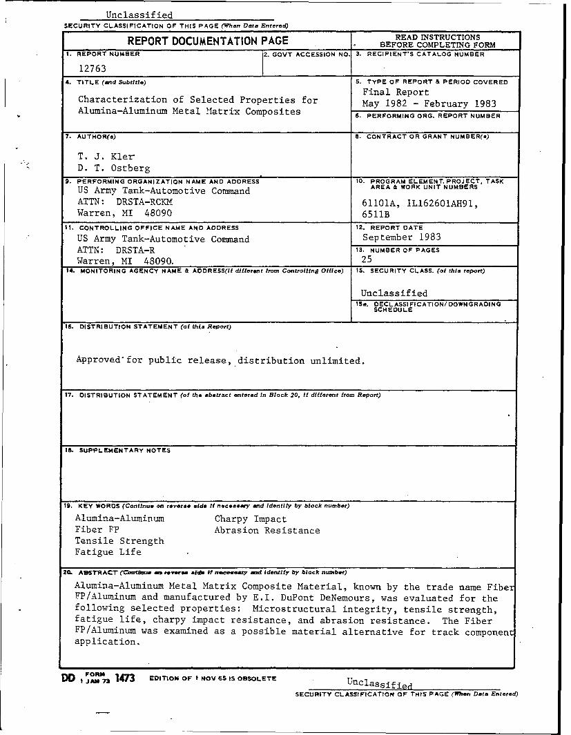
Alumina-Aluminum Metal Matrix Composite Material, known by the trade name FiberFP/Aluminum and manufactured by E.I. DuPont DeNemours, was evaluated for thefollowing selected properties: Microstructural integrity, tensile strength,fatigue life, charpy impact resistance, and abrasion resistance. The FiberFP/Aluminum was examined as a possible material alternative for track componentapplication.
DD I FOR 14n EDITION OF? IOV 6S IS OBSOLETE Unclassified
SECURITY CLASSIFICATION OF THIS PAGE (When Data Entered)

SECURITY CLASSIFICATION OF THIS PAGE(mmmn Data Entered)
SECURITY CLASSIFICATION OF THIS PAGE('W7.n Date Entered)
TABLE OF CONTENTS
Section Page
1.0. INTRODUCTION. . . . . . . . . . . . . . . . . . . . 5
2.0. SUMMARY . . . . . . . . ...... 6
3.0. CONCLUSIONS . . . . . . . . . . . . . . . . . . . . 7
4.0. RECOMMENDATIONS .................. 7
5.0. DISCUSSION. . . . . . . . . . . . . . . . . . . . . 8
5.1. Microstructural Properties . . . . ........ 9
5.2. Tensile Strength .......... . ....... 10
5.3. Fatigue Life. . . . . . . . . . . . . . . . . . . . 15
5.4. Impact Resistance . . . .. ... . . . .. . .. 18
5.5. Abrasion Resistance . . .. .. . . . ..... 22
LIST OF REFERENCES ..... ............ 24
DISTRIBUTION LIST .. ................ 25
2
LIST OF ILLUSTRATIONS
Figure Title Page
1. Streamlined, Reduced Area Tensile Bar . . . . . . . . 11
2. Tensile Bar Damage . . . . . . . . . . . . . . 12
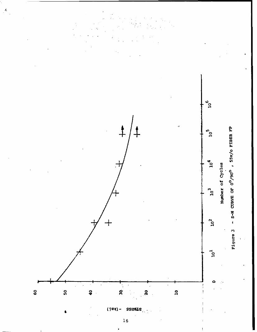
3. S-N Curve of 0o/90o, 55 v/o Fiber FP. . . . . . . . 16
4. Representative Fatigue Sample Fracture Face . . . . . 17
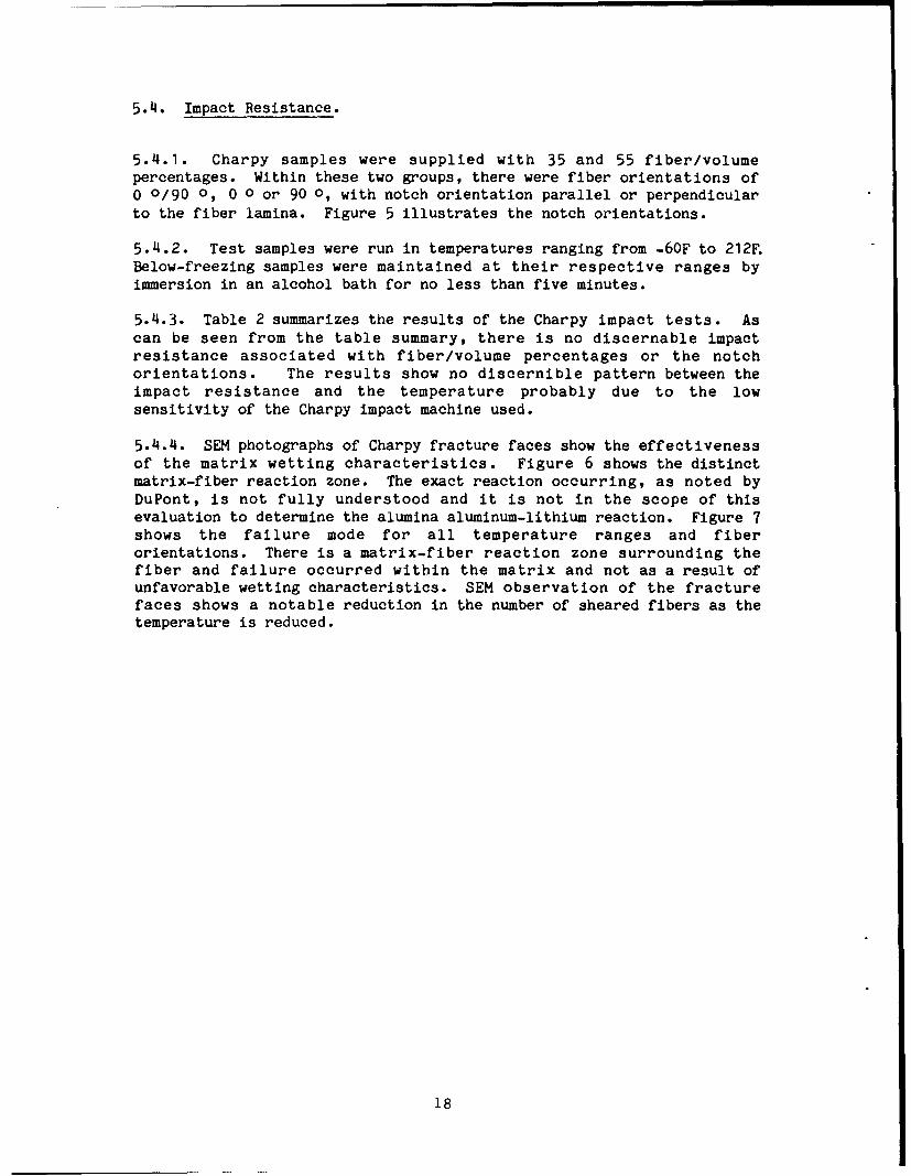
5. Charpy Notch-Fiber Orientation . . . . . . . . . 19
6. Matrix-Fiber Reaction Zone (2200X) . ........ 21
7. Matrix Failure (110OX) . . . . . . . . . . .. 21
3
LIST OF TABLES
Table Title Page
1. Relative Tensile Stength of Fiber FP/Aluminum. . . . . 14
2. Charpy Impact Test Results (Values in ft-lbs). . . . . 20
3. Relative Abrasion Resistance of Fiber FP/Aluminum. . . 23
4
1.0. INTRODUCTION
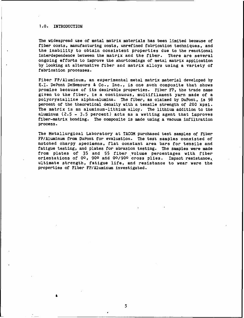
The widespread use of metal matrix materials has been limited because offiber costs, manufacturing costs, unrefined fabrication techniques, andthe inability to obtain consistent properties due to the reactionalinterdependence between the matrix and the fiber. There are severalongoing efforts to improve the shortcomings of metal matrix applicationby looking at alternative fiber and matrix alloys using a variety offabrication processes.
Fiber FP/Aluminum, an experimental metal matrix material developed byE.I. DePont DeNemours & Co., Inc., is one such composite that showspromise because of its desirable properties. Fiber FP, the trade namegiven to the fiber, is a continuous, multifilament yarn made of apolycrystalline alpha-alumina. The fiber, as claimed by DuPont, is 98percent of the theoretical density with a tensile strength of 200 kpsi.The matrix is an aluminum-lithium alloy. The lithium addition to thealuminum (2.5 - 3.5 percent) acts as a wetting agent that improvesfiber-matrix bonding. The composite is made using a vacuum infiltrationprocess.
The Metallurgical Laboratory at TACOM purchased test samples of FiberFP/Aluminum from DuPont for evaluation. The test samples consisted ofnotched charpy specimens, flat constant area bars for tensile andfatigue testing, and plates for abrasion testing. The samples were madefrom plates of 35 and 55 fiber volume percentages with fiberorientations of 00, 900 aftd 00/900 cross plies. Impact resistance,ultimate strength, fatigue life, and resistance to wear were theproperties of Fiber FP/Aluminum investigated.
5
2.0. SUMMARY
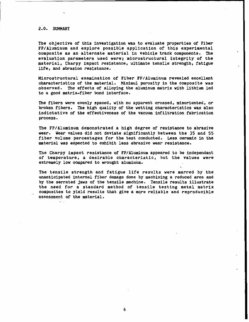
The objective of this investigation was to evaluate properties of FiberFP/Aluminum and explore possible application of this experimentalcomposite as an alternate material in vehicle track components. Theevaluation parameters used were; microstructural integrity of thematerial, Charpy impact resistance, ultimate tensile strength, fatiguelife, and abrasion resistance.
Microstructural examination of Fiber FP/Aluminum revealed excellentcharacteristics of the material. Minimul porosity in the composite wasobserved. The effects of alloying the aluminum matrix with lithium ledto a good matrix-fiber bond interface.
The fibers were evenly spaced, with no apparent crossed, misoriented, orbroken fibers. The high quality of the wetting characteristics was alsoindictative of the effectiveness of the vacuum infiltration fabricationprocess.
The FP/Aluminum demonstrated a high degree of resistance to abrasivewear. Wear values did not deviate significantly between the 35 and 55fiber volume percentages for the test conducted. Less ceramic in thematerial was expected to exhibit less abrasive wear resistance.
The Charpy impact resistance of FP/Aluminum appeared to be independantof temperature, a desirable characteristic, but the values wereextremely low compared to wrought aluminum.
The tensile strength and fatigue life results were marred by theunanticipated internal fiber damage done by machining a reduced area andby the serrated jaws of the tensile machine. Tensile results illustratethe need for a standard method of tensile testing metal matrixcomposites to yield results that give a more reliable and reproducibleassessment of the material.
6

3.0. CONCLUSIONS
The results of testing for various properties of Fiber FP leads to thefollowing conclusions:
3.1. The microstructural quality of Fiber FP Aluminum is excellent.There is good fiber-matrix bonding due to the lithium alloying of thematrix. There was a minimal amount of fiber pullout. The fact that aliquid metal infiltration process is used for casting Fiber FP impliesthat complex shaped parts of high microstructural composite qualitycould be made.
3.2. Ultimate tensile strength values obtained for Fiber FP samples arein conflict with the manufacturer's reported values probably due topreparation for testing. This illustrates the need for a morestandardized means of tensile bar fabrication and testing for compositematerial to give a more accurate assessment of the material'sproperties.
3.3. The delicate nature of a ceramic fiber matrix makes the machiningof reduced-area tensile bars a fragile and unpredictable operation. Theextent of fiber damage done while machining is not readily quantifiable.
3.4. Fatigue limit results for 00/900 55 v/o should be viewed in lightof the undetermined fiber degradation caused by machining. The valuesobtained show a stabilizing limit approaching 60 percent of the ultimatestrength values.
3.5. Due to the low impact resistance of the material, vehicle trackapplications would be very limited. However, due to the other excellentproperties, the selective use of this type of material may be desireablein the future for lightweight, high strength abrasian resistantapplications.
3.6. Fiber FP aluminum exhibited very good abrasive wearcharacteristics; The vitrified abrasion wheels exerted similar wearvalues for 00/900 for each fiber volume percentage.
4.0. RECOMMENDATIONS
None.
7
5.0. DISCUSSION
The Fiber FP/Aluminum test samples purchased by DuPont were cut fromplate castings with fiber-volume percentages of 35 and 55. Flat tensilebars, notched Charpy impact specimens, and flat abrasion plates were cutso the particular test samples had fiber orientations of 00, 900, and00/900.
Characteristics of interest for track application that were looked atinclude:
1. Microstructural integrity2. Ultimate tensile strength3. Fatigue limits4. Charpy impact resistance5. Abrasion resistance6. Cost7. Weight
8
5.1. Microstructural Properties.
In order to maximize the properties of composite material in general,the porosity of the material must be at a minimum. The matrix must beable to wet the fiber without causing fiber degradation, bunching of thefibers, or misorientating the fibers. Fiber FP/aluminum has excellentfiber-matrix density characteristics. There was minimal fiberdegradation and fibers maintained their spacing and orientations. Thewetting and infiltration efficiency of the matrix illustrated theeffectiveness of lithium alloying of the matrix and the merits of thevacuum infiltration process.
9
5.2. Tensile Strength.
Tensile strength tests were conducted in samples of 35 and 55 v/o withfiber orientations of 00, 900, and 00/900. Testing was done on anInstron Model 1333 closed loop, hydraulic testing system.
5.2.1. Composite material tensile testing is not a standardizedprocedure. Test samples can have reduced areas of various contours withtabs on the ends or samples may have a constant area. The reason forthe variation in testing is because different composites act differentlyunder tensile stress. Test specimens that use tabs glued to the endssometimes give results that don't accurately characterize the tensilestrength of the material. This is due, in part, to unequal stressdistribution caused by the strain compatibility of the tabs, bondingmedium, and sample.
5.2.2. Work done at the Army Materials and Mechanics Research Center(AMMRC) by Oplinger, Gandhi, and Parker (Report No. AMMRC-TR-82-27)"Studies of Tension Test Specimens for Composite Material Testing",proposes that the contour of reduced area tensile bars can bestreamlined to relate a more accurate accessment of the material'stensile properties. The report shows that unequal concentrations ofshear and tensile stress arise in the reduced area and tab-compositeinterface that alter the material's true load bearing characteristics,thereby giving an unreliable tensile strength value. Stress analysisdone by AMMRC showed that a streamlined taper lowered the shear andtensile stress concentrations inheraftt in tensile testing of compositematerials. This work was done on glass reinforced material but it wasfelt that the streamline design theory could be transposed to metalmatrix samples as well.
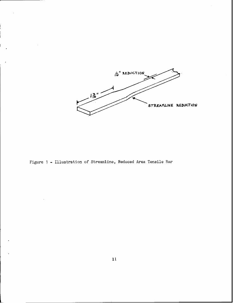
5.2.3. In light of the AMMRC work done on stress analysis of glasscomposites and with the desire to use an expeditious method of obtainingreliable tensile results, a reduced area, streamline design was used forthe Fiber PP tensile •ars. The dimensions~of the-tensile bars were 6inches X 1/2 inch X 1/10 inch, similar to a dogbone design, but with astreamlined radius. Machining was done with a fine grit, water cooledsurface grinder. Figure 1 illustrates the streamline tensile barconfiguration.
5.2.4. We felt that the minimum force required to grip the samples withthe serrated jaws of the tensile machine would be such that the fiberintegrity would not be altered. This did not prove to be the case,however, as average stress results ranged from 20 - 50 ksi, values 50percent lower than DuPont's claims. Inspection of the tensile bar endsrevealed significant fiber damage on some of the bars. Figure 2 shows atensile bar with the most severe case of tensile bar grip penetration.
10
"$1"rEAALI NE !REDUCTION
Figure 1 - Illustration of Streamline, Reduced Area Tensile Bar
11
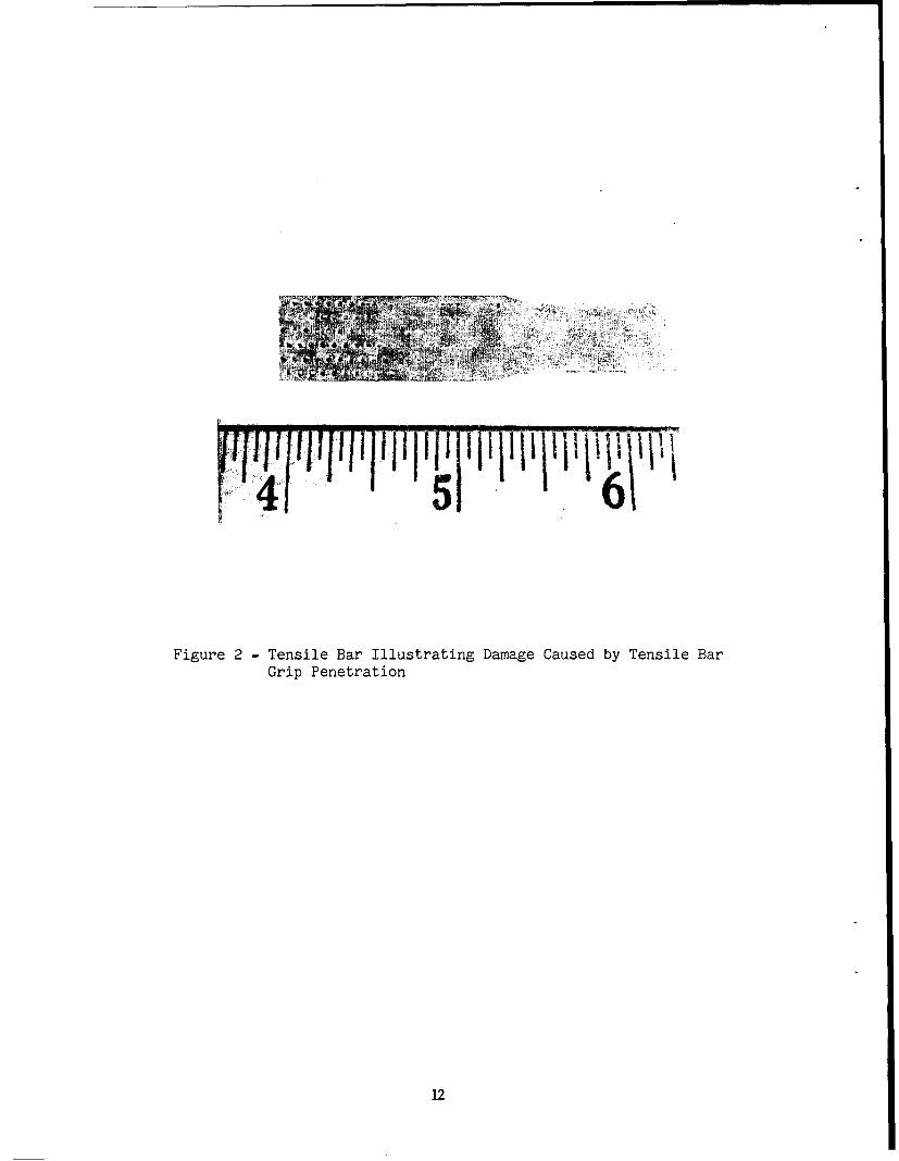
Figure 2 - Tensile Bar Illustrating Damage Caused by Tensile BarGrip Penetration
12
Microscopic measurement of the surface damage caused by the serratedjaws showed that, in the worst case, indentations averaged 1/64 inchdeep and 2/64 inch wide to form a diamond-shape impression. The effectsthat the indentations had on the ultimate strength can only beestimated, not determined. Considering a jaw penetration depth of 1/64inch with six rows of serrations on both sides of the bars,approximately 10 percent of the cross sectional area was directlyaffected. The fact that each tensile bar broke in the midsection of thereduced area leads to the conclusion that the streamline design may be aviable means of tensile test design. The damage on the sample done bythe serrated jaw shows a 10 percent reduction in the effective cross-sectional area. These yields, however, are well below DuPont's reportedvalues. The only other explanation for the low tensile strength valuesis that damage was done to the fiber integrity while machining thereduced area. One theory is that due to the vibratory effects of thesurface grinder, significant internal fiber damage occurred. Thebrittle nature of the alumina could lead to broken or severely flawedfibers. This would seem to have a more acute effect on cross-plycomposites (00/900).
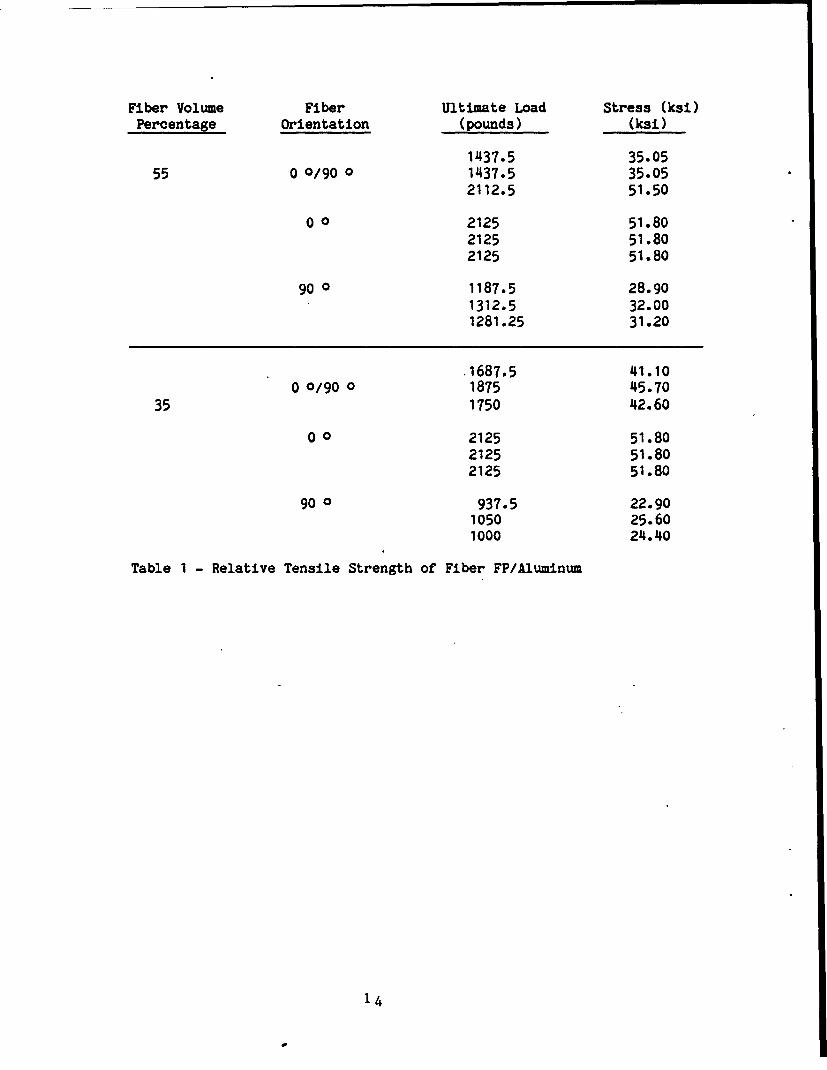
5.2.6. Table I compares the relative stress results obtained in tensiletesting. The cross-sectional area used to calculate the stress does nottake into account the 10 percent area loss due to the serrated jaws ofthe tensile machine or the fiber degradation that may have occurred dueto machining the reduced area.
13
Fiber Volume Fiber Ultimate Load Stress (ksi)Percentage Orientation (pounds) (ksi)
1437.5 35.0555 0 0/90 0 1437.5 35.05
2112.5 51.50
0 0 2125 51.802125 51.802125 51.80
90 0 1187.5 28.901312.5 32.001281.25 31.20
.1687.5 41.100 0/90 0 1875 45.70
35 1750 42.60
0 o 2125 51.802125 51.802125 51.80
90 0 937.5 22.901050 25.601000 24.40
Table 1 - Relative Tensile Strength of Fiber FP/Aluminum
14
5.3. Fatigue Life.
Fatigue testing was carried out on a sample set with a fiber/volumepercentage of 55 and an orientation of 0 0/90 0 at a temperature of 70F+ 5F. This particular volume and orientation was chosen because anypossible track application would require the desirable wearcharacteristics inherant in having more ceramic in the material andmultidirectional loading strength.
A uniaxial load was applied with a stress ratio of 0 at a frequency of 1Hz. The resulting curve, shown in Figure 3, was produced by a linearregression program interfaced with a Hewlett-Packard Series 9800 plotterpac. The values used in the curve do not consider the fiber damage asnoted in the previous section. Scanning Electron Microscope (SEM)analysis of the fracture face showed virtually no fiber pullout. Figure4 is a representative fracture face photograph showing the extent offiber pullout.
15
4,n
~~W
00
"4t
.44-0 mz4 14;-
0
cnn
""4
kr1.
Ln2 m
ssmus162
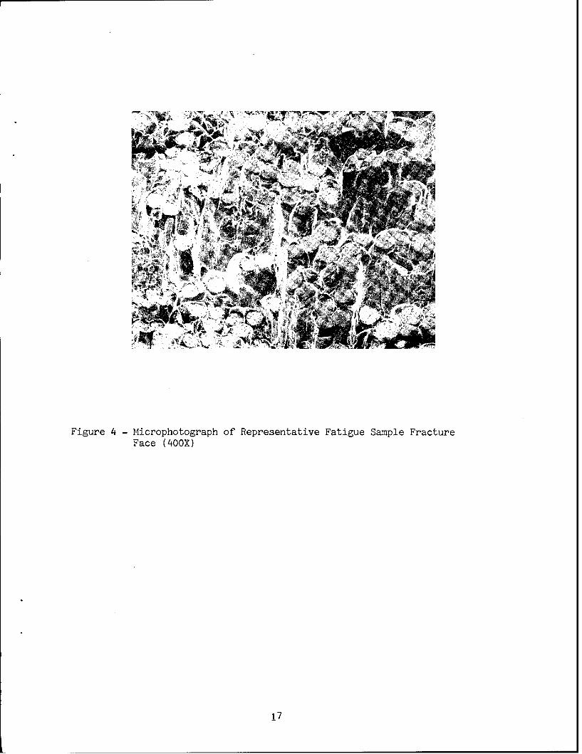
Figure 4 - Microphotograph of Representative Fatigue Sample Fracture
Face (400X)
17
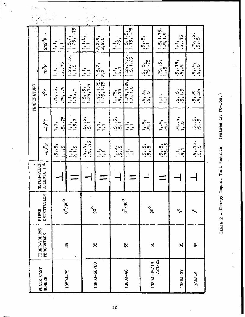
5.4. Impact Resistance.
5.4.1. Charpy samples were supplied with 35 and 55 fiber/volumepercentages. Within these two groups, there were fiber orientations of0 0/90 0, 0 0 or 90 0, with notch orientation parallel or perpendicularto the fiber lamina. Figure 5 illustrates the notch orientations.
5.4.2. Test samples were run in temperatures ranging from -60F to 212F.Below-freezing samples were maintained at their respective ranges byimmersion in an alcohol bath for no less than five minutes.
5.4.3. Table 2 summarizes the results of the Charpy impact tests. Ascan be seen from the table summary, there is no discernable impactresistance associated with fiber/volume percentages or the notchorientations. The results show no discernible pattern between theimpact resistance and the temperature probably due to the lowsensitivity of the Charpy impact machine used.
5.4.4. SEM photographs of Charpy fracture faces show the effectivenessof the matrix wetting characteristics. Figure 6 shows the distinctmatrix-fiber reaction zone. The exact reaction occurring, as noted byDuPont, is not fully understood and it is not in the scope of thisevaluation to determine the alumina aluminum-lithium reaction. Figure 7shows the failure mode for all temperature ranges and fiberorientations. There is a matrix-fiber reaction zone surrounding thefiber and failure occurred within the matrix and not as a result ofunfavorable wetting characteristics. SEM observation of the fracturefaces shows a notable reduction in the number of sheared fibers as thetemperature is reduced.
18
notch parallel to plies
of 00/900 orientation
"notch perpendicular to pliesof 00/90 orientation
Figure 5
Example of Charpy SpecimenNotch-Fiber Orientation
19
LA Ln
-CU LAn; LA M b-L a
a~ af an aý *ý *U\ 1l.AnLr LAI-40 A AA-' LA) LM r *Ln
LA; Lf;LA* (%.J LA n
LA n t- LAý LA at- -LA 01CM * * c A LL
o ý *ý LA a- an aý LA a aAo -r *- C LAN Cm -CIjLA -LA LA" a a
t- -n -n -n -- -- - - -
AOL LAjC
(4 ('iNtE- CMaz LA M L
C LA t- '- LA Ln VLA . a-L -A
E-. o *f *n - L A- a LLý A. LANc~~< 0 -ý af -LA -Lrý OA I'-. LA- * -*
Ln LA't- LAn j tl- 01 * C\,JLA -
-. * t- "LAI * LnL a r LAL Ln Lf
E- - - - - -4
C. t*- 01j LAý LAý aý - L LnL0 -ý -n LA a- -- aalfC*a *a
0 af n n L .4. an -LAýýt LA
o LA L LA L * LLAA L * -L
434.,
E-4 0
= 0
00.0 0 0.
110
E- -4<: .70%co
U. 0
E--
\0 20
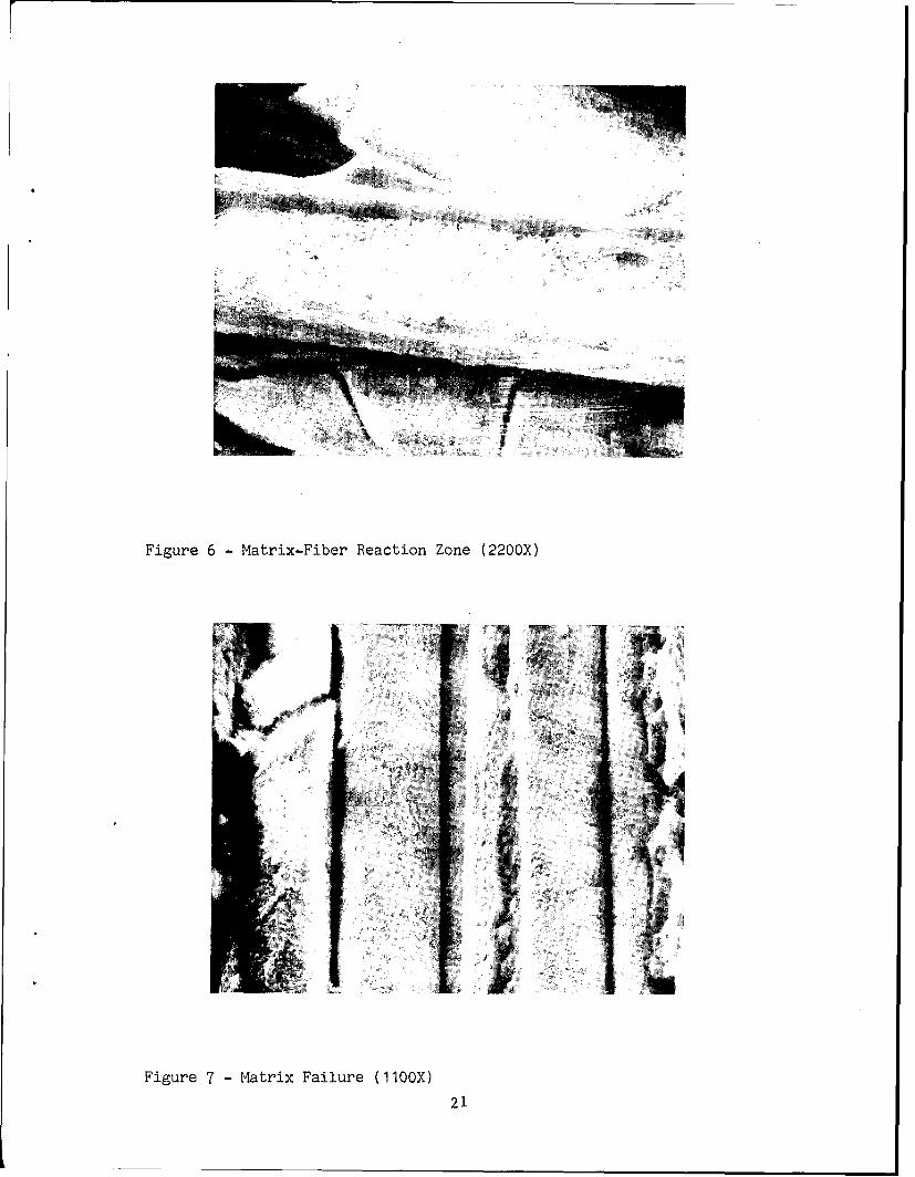
Figure 6 - Matrix-Fiber Reaction Zone (2200X)
Figure 7 - Matrix Failure (110OX)
21
5.5. Abrasion Resistance.
5.5.1. Abrasion resistance of the Fiber FP was determined by using 4inch X 4 inch X 1/2 inch samples on a Taber Model 503 Abraser.
5.5.2. The Taber Abraser allows for a constant load to be applied onthe abrasive-test material interface as the test material rotates. Aload of 1000 grams was maintained for each test. Each sample was runfor 10,000 cycles using either an H-10 grit abrasive wheel or a coarser,H-22 grit wheel.
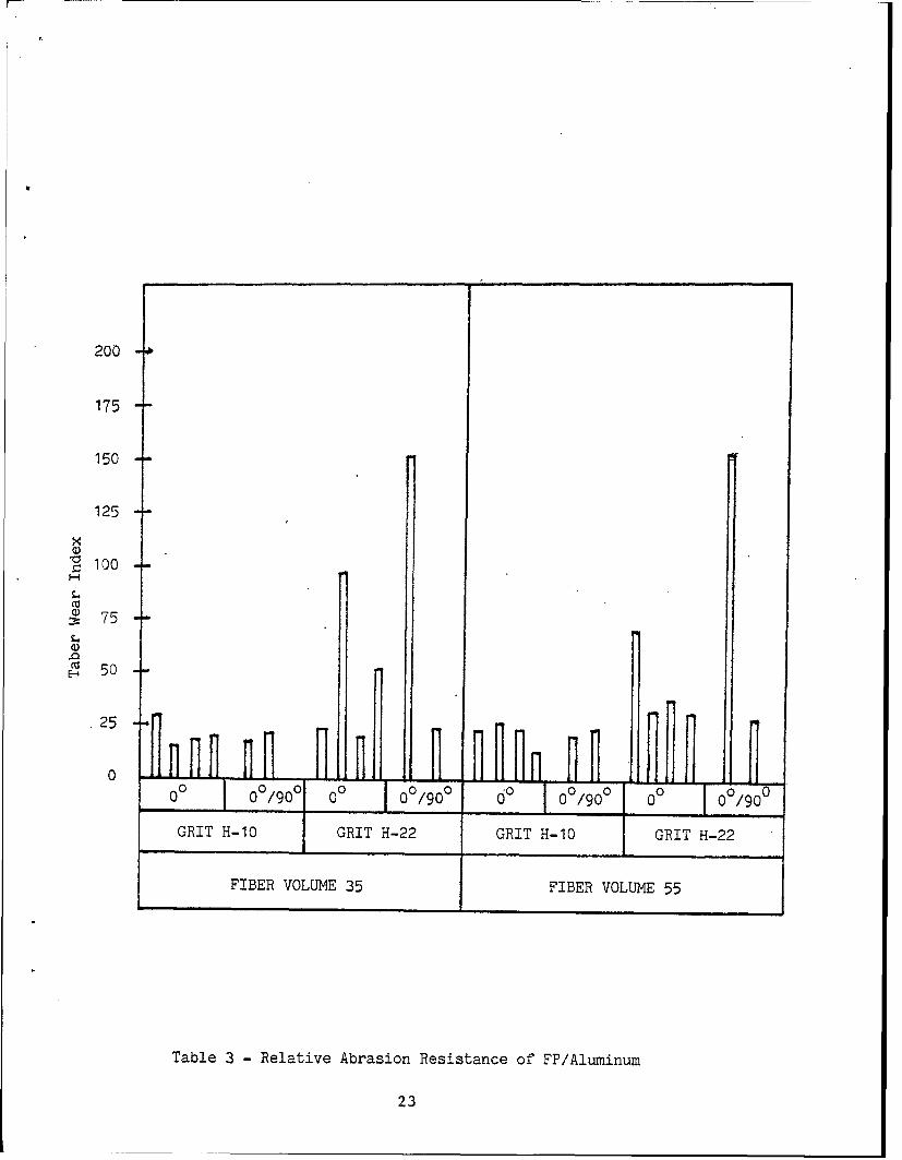
5.5.3. A weight loss method of the relative abrasion resistance wasused, called the Taber Wear Index. This method is based on the weightloss of the test sample in milligrams per throusand cycles. Table 3compares the relative abrasion resistance between samples tested.
5.5.4. Using the H-10 grit abrasive wheels, there is no distinctionbetween the wear characteristics of 35 or 55 fiber/volume percentages.Each was highly resistive to abrasion. The H-22 grit abrasive wheelsgenerally had a higher effect on the Fiber FP, but more 00/900 sampletests would be required on the H-22 wheels in order to obtain areasonable standard deviation and a more accurate assessment of thematerial's wear index. The limited number of abrasion test panelspurchased did not allow this.
22
200
175
150
125
x
S100
S75
.c 50
25
00 0 0*do 0/90 00 000 /90 0 0 /90 00 /0 0 0 /0
GRIT H-l0 GRIT H-22 GRIT H-10 GRIT H-22
FIBER VOLUME 35 FIBER VOLUME 55
Table 3 - Relative Abrasion Resistance of FP/Aluminum
23
LIST OF REFERENCES
G. B. Bilow and J. T. Tesson, "Fabrication Process for AluminumComposites", Air Force Materials Laboratory, Air Force SystemsCommand, Wright-Patterson Air Force Base, Ohio (1974)
A. R. Champion, W. H. Krueger, H. S. Hartmann and A. K. Dhingra, "FiberFP Reinforced Metal Matrix Composites" presented at the SecondInternational Conference on Composite Materials, Toronto, Canada(1978)
M. J. Klein, G. K. Schmitz and A. G. Metcalfe, "Effect of Interfaces inMetal Matrix Composites on Mechanical Properties" Report No. 2 & 3,Air Force Materials Laboratory, Air Force Command, United StatesAir Force, Wright-Patterson Air Force Base, Dayton, Ohio 45433(1970, 1971)
Kenneth G. Kreider, "Metal Matrix Composites", Academic Press, NY (1974)
Donald W. Oplinger, Kanu R. Gandhi and Burton S. Parker, "Studies ofTension Test Specimens for Composite Material Testing", ArmyMaterials and Mechanics Research Center, Watertown, Massachusetts(1982)
24
DISTRIBUTION LIST
Copies
Defense Technical Information Center 15ATTN: TIPDRCamerson StationAlejcandria, VA 22314
Director 2US Army Materials and Mechanics
Research CenterATTN: DRXMR-MWatertown, MA 02172
Commander 2US Army Tank-Automotive CommandATTN: DRSTA-TS (Technical Library)Warren, MI 48090
NASA-LERCTechnical Library21000 Brook Park Rd.Cleveland, OH 4 41 3 5
E. I. DuPont DeNemours & Co., Inc. 3Pioneering Research LaboratoryExperimental StationWilmington, DE 19898ATTN: W. H. Krueger, H. J. Vusbaum, H. S. Hartmann
25