systems engineering design project (enpm-643)...
TRANSCRIPT

Systems Engineering Design Project (ENPM-643)
Instructor: Mark A. Austin
Smart School ID System
Submitted By: Alpa Kothari, Neha Dua

Table of Contents
1. Introduction Purpose: Setup Problem
Topics: Overview of Smart School ID system architecture, system framework and boundary, terminology.
2. Goals, Scenarios and Use Cases Purpose: Develop use cases, scenarios and system requirements Topics: Goals and Scenarios, actors, initial use cases
3. Generation of Requirements from Use Cases Purpose: Generate system/ subsystem requirements Topics: Generate the high level or system requirements from the use cases, synthesize and break down high level requirements into low level requirements, organize the requirements into layers, traceability of requirements to use cases
4. Models of System Behavior Purpose: Create simplified models of behavior Topics: Activity Diagrams, Statechart Diagrams
5. System Specifications Purpose: Generate the specifications for the component requirements Topics: Assign qualitative and quantitative values to requirements and generate specifications.
6. Component System Testing, Validation and Verification Purpose: Develop Procedures of system test, verification and validation Topics: Primary verification plan, verification traceability matrix
7. Conclusion 8. References
1. PROBLEM STATEMENT Security and student accountability is a major concern in schools these days. Nowadays, many schools in the US, UK, Japan and India are considering alternatives and solutions in order to incorporate access control and tracking mechanisms and also to automate attendance reconciliation. The purpose of this project is to apply the systems engineering principles to propose the Smart School ID System. The Smart School Id system is a presence detection and access control system designed to restrict any unauthorized access and allow tracking of students/staff and visitors inside the school. Our objective in this project is to use our knowledge of UML to analyze the system requirements, functions & specifications and use systems validation and verification strategies to put forward a robust test procedure.
1.1 INTRODUCTION In recent years, automatic identification procedures have become very popular in many service industries, purchasing and distribution logistics, manufacturing companies, material flow systems and recently schools. The barcode labels that had triggered a revolution in identification systems some time ago are being found to be inadequate in an increasing number of cases. Barcodes might be extremely cheap, but they have a very low storage capacity and they cannot be reprogrammed. Optical character recognition was first used in the 1960s. Even though it supports a high density of information and a possibility of reading the data visually, OCR systems have failed to become universally applicable because of their high price and the complicated readers that they require. Biometric procedures (voice identification & Fingerprinting) are secure but are ideally used in High security, low traffic areas. Smart cards are ideal where undesired access and manipulation of data is a risk, but their flexibility can be enhanced by using contactless smart cards using the RFID technology. Some of the advantages of RFID over Barcode
– Human intervention is required to scan a barcode, whereas in most applications an RFID tag can be detected "hands off."
– Barcodes must be visible on the outside of product packaging. RFID tags can be detected regardless of their orientation
– You must have "line of sight" to read a barcode. Line of sight is not required for RFID tagged objects
– The readability of barcodes can be impaired by dirt, moisture, abrasion, or packaging contours. RFID tags are not affected by those conditions.
– RFID tags have a longer read range than barcodes. – RFID tags have read/write memory capability; barcodes do not. – More data can be stored in an RFID tag than can be stored on a barcode.
In general terms, RFID (Radio Frequency Identification) is a means of identifying a person or object using a radio frequency transmission. It uses radio waves to automatically identify physical objects (either living beings or inanimate items). Therefore, the range of objects identifiable using virtually everything. Thus, RFID is an example of automatic identification (Auto-ID) technology by which a physical object can be identified automatically.
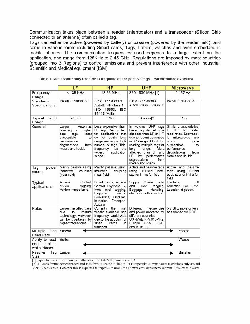
Communication takes place between a reader (interrogator) and a transponder (Silicon Chip connected to an antenna) often called a tag. Tags can either be active (powered by battery) or passive (powered by the reader field), and come in various forms including Smart cards, Tags, Labels, watches and even embedded in mobile phones. The communication frequencies used depends to a large extent on the application, and range from 125KHz to 2.45 GHz. Regulations are imposed by most countries (grouped into 3 Regions) to control emissions and prevent interference with other Industrial, Scientific and Medical equipment (ISM).

1.1.1 HOW RFID WORKS
An RFID system is an integrated collection of components that implement an RFID solution. – Tag. This is a mandatory component of any RFID system. – Reader. This is a mandatory component, too. – Reader antenna. This is another mandatory component. Some current readers
available today have built-in antennas – Controller. This is a mandatory component. However, most of the new-
generation readers have this component built in to them. – Sensor, actuator, and annunciator. These optional components are needed for
external input and output of the system. – Host and software system. Theoretically, an RFID system can function
independently without this component. Practically, an RFID system is close to worthless without this component.
– Communication infrastructure. This mandatory component is a collection of both wired and wireless network and serial connection infrastructure needed to connect the previously listed components together to effectively communicate with each other.
In a typical system tags are attached to objects that need to be identified. Each tag has a certain amount of internal memory (EEPROM) in which it stores information about the object, such as its unique ID (serial) number. When such a tagged object is presented in front of a suitable RFID reader, the tag transmits this data to the reader (via the reader antenna). The reader then reads the data and has the capability to forward it over suitable communication channels, such as a network or a serial connection, to a software application running on a computer. This application can then use this unique data to identify the object presented to the reader. It can then perform a variety of actions such as updating the location information of this object in the database, sending an alert to the floor personnel, or completely ignoring it (if a duplicate read, for example).

1.2 SYSTEM INTRODUCTION The Smart School ID System makes student security possible and efficient. A typical school consists of 2 or 3 school entrances, student labs, student activity rooms, student gym/courts, administrative offices, media, archive rooms. The Smart School ID System incorporated in such a school, allows presence detection & access control in all areas inside the school. School entrances are generally restricted to two. The presence detection/access control function is comprised of a wired/wireless sensor network of readers that is installed in school buildings to detect presence of students with badges or tags. All students/staff are issued permanent access IDs on their recruitment into the school. Students/staff who have lost or forgotten their tags and Visitors are issued day access ids.
Layout Figure A: School Architectural Layout
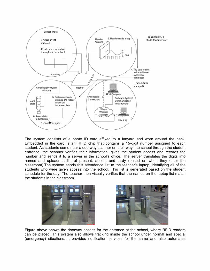
The system consists of a photo ID card affixed to a lanyard and worn around the neck. Embedded in the card is an RFID chip that contains a 15-digit number assigned to each student. As students come near a doorway scanner on their way into school through the student entrance, the scanner verifies their information, gives the student access and records the number and sends it to a server in the school's office. The server translates the digits into names and uploads a list of present, absent and tardy (based on when they enter the classroom).The system sends this attendance list to the teacher's laptop, identifying all of the students who were given access into the school. This list is generated based on the student schedule for the day. The teacher then visually verifies that the names on the laptop list match the students in the classroom. Figure above shows the doorway access for the entrance at the school, where RFID readers can be placed. This system also allows tracking inside the school under normal and special (emergency) situations. It provides notification services for the same and also automates
Tag carried by a
student/visitor/staff Trigger event
initiated
School door open
Readers are turned on
throughout the school
Back up
(Date & time
stamped)

attendance reconciliation. To ensure data security, only Authorized users maintain the system database. The Smart school ID system offers security advantages since administrators would immediately know if a student didn't show up for class and could notify parents quickly. School officials could also quickly identify anyone who didn't belong on campus if they weren't wearing an RFID badge. But the main draw is a more efficient and accurate way to track and verify attendance.
1.3 PROJECT OUTLINE Initially use case analysis is done based on the customer/stakeholder requirements. From the use case analysis, high – level requirements are generated and are further synthesized and broken down into low level requirements. Component requirements and their design specifications are also identified. The system behavior models are also generated documenting the sequences of tasks making up activities governed by conditional logic and flows driven by internal processing. State chart diagrams are also specified describing all possible behaviors in a system element through its traversal of its different states and transition arcs.
1.4 SYSTEM FRAMEWORK & BOUNDARY The Smart school system ID can be depicted as a framework of the following systems. This describes the system boundary.

2. GOALS, SCENARIOS and Use Cases
2.1 Goals and Scenarios
Goal 1: The system must be secure
• Scenario 1.1 – The system should provide the school with a reliable tracking mechanism.
• Scenario 1.2 – All updates to the database should be monitored by a system administrator
• Scenario 1.3 – Emergency tracking and database updates require secure login to the system
• Scenario 1.4 – Unauthorized person should not be allowed access. • Scenario 1.5 – The school should verify the visitor credentials before giving access Ids • Scenario 1.6 – In event of unauthorized access, the system should generate an alert
and deny access. Goal 2: The system must be efficient
• Scenario 2.1 – The system should use a database management system which supports large number of students, staff and visitors.
• Scenario 2.2 – The system should use readers which use anti-collision algorithms to manage reading and tracking of large number of tags.
• Scenario 2.3 – Database accesses and updates made by the readers for tracking purposes should have minimum latency
• Scenario 2.4 – Data validation and account authentication should be done with minimum latency
Goal 3: The system must be usable
• Scenario 3.1 – The system should be easy to use. • Scenario 3.2 – The system should have easy to use graphical user interface for the
entrance staff and authorized users to update or access the system.
• Scenario 3.3 – The system should provide alerts wherever required. • Scenario 3.4 –The system should provide attendance reconciliation and print reports. • Scenario 3.5 – The system should be able to be used for tracking students/staff and
visitors with tags. Goal 4: The system must be reliable
• Scenario 4.1 – The system and database should be available at all times. • Scenario 4.2 – The system readers should work whenever initiated. • Scenario 4.3 – The readers should correctly read the tag data and update the database
accurately.
• Scenario 4.4 - Back up Server ensures secure data storage Goal 5: The system must be easy to maintain
• Scenario 5.1 – The system database should be well protected from crashes. • Scenario 5.2 – Database should be easily accessible.

• Scenario 5.3 - The entrance door should close after one revolution. Goal 6: The system must track accurately and maintain data integrity
• Scenario 6.1 – The system should make use of anti-collision algorithms to handle signal collision from different tags.
• Scenario 6.2 – The system should allow database access and update by authorized users only.
• Scenario 6.3 – The system should not allow more than two users to access the same record for update simultaneously.
• Scenario 6.4 –The system should track students accurately and give the correct location of the student.
Goal 7: The system must provide authorized access
• Scenario 7.1 – Every student/staff should have a permanent access id tag • Scenario 7.2 – Every visitor should get a day access id from the school entrance staff
for access to the school
• Scenario 7.3 – There should be two access controlled entrances: one for students and the other for visitors and staff
• Scenario 7.4 A day access ID should be given Student/ staff who have forgotten their ID or lost it
• Scenario 7.5Entrance to the school should be not be allowed from any other entrances from the outside
• Scenario 7.6 The day access ID should be valid only for a day
2.2 USE CASE ANALYSIS
2.2.1 Actors
1. School Authority 2. System Administrator 3. School Staff 4. Entrance Staff 5. Authorized User 6. Student 7. Visitor 8. NT (No Tag) Staff 9. NT (No Tag) Student 10. Parents
2.2.2 Identify the roles of actors
• School Authority: Approves issuance of tags to the students/ staff or visitors.
• System Administrator: Issues tags to staff and student. Maintains the database, database recovery etc. Can trigger tracking under special situations. Creates accounts for authorized users (or staff) to provide them access the system, print/ generate reports, accesses the database for updating records.
• School Staff: User of the system
• Entrance Staff: Issues day ID tags to the visitors/students and staff, handle return of the tags, accesses the database for updating records.
• Authorized User: Accesses the database to update, delete or add records, print/ generate reports
• Student: Accesses the system to enter the school, requests for a permanent tag, requests the access to a restricted area, returns the permanent tag
• Visitor: Accesses the system to enter the school, requests for a day ID tag, requests the access to a restricted area, returns the day id tag
• NT Staff: The staff who lost or forgot to get the tag to school
• NT Student: The student who lost or forgot to get the tag to school
• Parents: Requests initiation of tracking, visit school
2.3 Initial Use Case Modeling The use cases represent system goals and system functions. A use case view focuses on the high-level system functionality, without revealing the details of the objects that will implement the behavior. It is an abstraction of a system response to external inputs and accomplishes a task that is important from a user’s point of view.
The use cases have been packaged into six (6) packages. Below are the use case diagrams representing the Smart School ID System.
Figure 2: Initial Un-Partitioned use-case diagram of Smart School ID System

Figure 3: Issue/ Return Smart ID Tag Package - use-case diagram of Smart School ID System

Figure 4: Access Control Package - use-case diagram of Smart School ID System

Figure 5: Database Access Control Package- use-case diagram of Smart School ID System

Figure 6: Login/ Logout Control Package- use-case diagram of Smart School ID System

Figure 7: Special Features Package- use-case diagram of Smart School ID System

Figure 8: Tracking Package- use-case diagram of Smart School ID System

2.4 Use Case Narrative
USE CASE 1– ISSUE STUDENT/ STAFF SMART ID TAG
Brief Description This use case narrative allows the school to issue permanent access Ids to newly recruited school staff and newly admitted students and also to school staff and students who have lost their permanent tags. Actors
1. Student 2. School Staff 3. School Authority 4. System Administrator
Flow of Events:
1. Basic Flow:
1.1. The school authority collects all the information from the student or the staff member and gives to the system administrator
1.2. The system administrator logs in to the system 1.3. The system administrator gives the smart tag ID to the student or the staff
member 1.4. The system administrator updates the database <include access data> with the
name, information, tag id information (student Id number) and the access information.
Assumptions:
1. Student has been admitted to school Staff member has been recruited. 2. The student/staff who has lost the tag, has been issued a day access id once but
now requires a permanent access tag for daily purposes. Precondition:
1. The system should be up and running. 2. System administrator is logged in
Postcondition:
1. Student/Staff member have appropriate access. 2. The system administrator must log out after he is done with the updates<include use
case logout>

USE CASE 2– ISSUE DAY SMART ID TAG
Brief Description This use case narrative allows the visitor or NT student/staff to obtain access tags to enter the school building. Actors
1. Visitor 2. Entrance Staff 3. NT Student 4. NT Staff
Flow of Events: 1. Basic Flow:
1.1 The visitor enters the school 1.2 The visitor enters his details in a form describing his name, address, photo, and
the kind of access he requires and purpose of visit. 1.3 The entrance staff verifies and enters his information into the database. 1.4 The entrance staff determines what kind of access the visitor should get. 1.5 He updates the same in the database <Include access data> 1.6 The entrance staff supplies photo visitor id to the visitor.
2. Alternate Flow 1:
2.1 The visitor enters the school 2.2 The visitor enters his details in a form describing his name, address, photo, and
the kind of access he requires and purpose of visit. 2.3 The entrance staff verifies and enters his information into the database. 2.4 The entrance staff rejects his request and decides not to allow him inside the
school premises. 2.5 The entrance staff enters this information in the database for future reference
<Include access data> 3. Alternate Flow 2:
3.1 A student/staff comes to school without his tag ID 3.2 If the student/staff has lost his ID, he reports it to the entrance staff. 3.3 The student/staff enters his details in a form describing his name, address,
class and teacher. 3.4 The entrance staff verifies the kind of access that he requires. 3.5 The entrance staff verifies and enters his information into the database.
<Include access data> 3.6 The entrance staff gives him the ID valid for a day
4. Alternate Flow 3:

4.1 A student/staff comes to school without his tag ID. 4.2 If the student/staff has lost his ID, he reports it to the entrance staff. 4.3 The student/staff enters his details in a form describing his name, address,
class and teacher. 4.4 The entrance staff verifies and enters his information into the database.
<Include access data> 4.5 The staff rejects the request as it does not find any matching information. 4.6 The staff updates the database <include access data>
Assumptions:
1. The database is set up and entrance staff is the primary decision maker to approve or reject access request.
2.. Visitor tags/temporary student/staff Ids are valid only for a school day.
Precondition:
1. The visitor enters the school without an authorized smart ID tag 2. Entrance Staff is logged in to the system
Postcondition:
1. The visitor/ NT staff or NT student gets the appropriate ID and access. 2. The entrance must log out one the updates are complete
USE CASE 3– ATTENDANCE RECONCILATION
Brief Description This use case narrative allows student inside the school building and ensures that the student attendance is recorded. Actors
1. Student
Flow of Events: 1. Basic Flow:
1.1 The student enters the school 1.2 The student swipes the tag on a controlled doorway with RFID reader at the
main entrance 1.3 The RFID reader system recognizes the tag after verifying with the
database<include access data> 1.4 They match, the door gives access to the student and the student can then
enter

1.5 The server database gets updated with a time stamped entry. <Include access data>
1.6 The server translates the entries into student names and uploads a list of present, absent and tardy students
1.7 The teacher is provided with a list of students as a printout or through laptop connected in each class and she verifies it as she enters the class
1.8 The teacher finds all the students in the list present in the class 2. Alternate Flow 1:
2.1 The student enters the school 2.2 The student swipes the tag on the RFID reader at the main entrance 2.3 The RFID reader system fails to recognize the tag. 2.4 The student is denied access. 2.5 Student goes to the entrance staff.
3. Alternate flow 2:
3.1 The student enters the school 3.2 The student swipes the tag on a controlled doorway with RFID reader at the
main entrance 3.3 The RFID reader system recognizes the tag after verifying with the
database.<include access data> 3.4 They match, the door gives access to the student and the student passes
successfully 3.5 The server database gets updated with a time stamped entry. <Include access
data> 3.6 The server translates the entries into student names and uploads a list of
present, absent and tardy students. 3.7 The teacher is provided with a list of students as a printout or through laptop
connected in each class and she verifies it as she enters the class 3.8 The teacher finds one or more students in the list missing in the class. The
teacher send out a alert and tracking is initiated<include tracking in special situations>
Assumptions:
1. There are two separate entrances for students and visitors. 2. Students are wearing their own tags 3. Entrance to the school should not be allowed from any other entrance from the outside. 4. The readers work at all times 5. The door will restrict access after one revolution
Precondition:
The RFID system is working properly. Postcondition:
Access is allowed/ denied and the database is updated

USE CASE 4 – VISITOR /STAFF ACCESS TO ENTRANCE
Brief Description This use case narrative allows access to the visitor/staff inside the main building. Actors
1. Visitor 2. School staff
Flow of Events: 1. Basic Flow:
1.1 The visitor/school staff goes to the main access door of the school building 1.2 The visitor swipes the card on the reader 1.3 The reader at the door recognizes the tag used by the visitor 1.4 The database is updated with the visitor /school staff information and is time
stamped<include access data> 1.5 The door opens for the visitor/staff
2. Alternate Flow:
2.1 The visitor/staff goes to the main access door of the school building 2.2 The reader at the door does not recognize the tag used by the visitor/staff 2.3 The door does not open for the visitor/staff 2.4 The visitor/staff goes back to the entrance staff
Assumptions:
1. Visitor/staff Door to the main entrance is access controlled. It opens only if the reader recognizes the tag.
2. The reader here works at all times 3. The door should restrict access after one revolution.
Precondition:
1. Visitor has taken access tag from the entrance staff. 2. School staff has IDs
Postcondition:
Visitor/ staff allowed or denied access into the building
USE CASE 5 – RESTRICTED AREAS ACCESS
Brief Description This use case narrative allows access to some areas in the school is restricted according to individual requirement.

Actors
1. Student 2. Visitor 3. School staff 4. System Admin 5. School Authority
Flow of Events: 1. Basic Flow:
1.1 The student/school staff or visitor tries to access the restricted area entrance. 1.2 The reader recognizes the tag id. 1.3 The door opens and the student/school staff or visitor is given access to the
area. 1.4 The database gets updated <include access data>
2. Alternate Flow 1:
2.1 The student/staff or visitor tries to access the restricted area 2.2 The reader fails to recognize the tag id 2.3 The door remains closed and the student/staff or visitor is not granted access
to the restricted area. 2.4 The database is updated <include access data> 2.5 The student/staff/visitor goes to the system admin or school authorities to get
the additional access. Assumptions:
1. Access to the restricted area has been given to a visitor or student/ staff if he is required to enter the area.
2. Playground entrances, lab entrances, inventory and media centers all will have restricted access.
3. The readers here work all the time. Precondition:
Students/staff/Visitors trying to enter a restricted area have a tag id. Postcondition:
The student/staff/visitor are either allowed or denied access.
USE CASE 6 – REQUESTS A LOGIN
Brief Description This use case narrative allows school staff to request the system administrator to provide login access to the system
Actors
1. School Staff 2. System Administrator 3. School Authority
Flow of Events:
1. Basic Flow:
1.1 A staff member authorized by the school requests system administrator for access to the system
1.2 The system administrator verifies the staff member’s permission and information
1.3 The system administrator then issues a login id and an initial password to the requesting staff member
1.4 The user has the option to change the password to own choice 1.5 The database is updated with the login information <include access data>
2. Alternate Flow 1:
2.1 A staff member requests for access to the system 2.2 The system administrator verifies the staff member’s permission and
information 2.3 The system administrator finds that the staff member has not been authorized 2.4 The system administrator directs the user to the school authorities 2.5 The system administrator also reports the matter to the school authority 2.6 The system administrator updates the database<include access data>
Assumptions:
The system administrator has the power to create a new user account
Precondition:
The person requesting access belongs to the school staff Postcondition:
Appropriate action is taken
USE CASE 7 – TRACKING IN NORMAL SITUATIONS
Brief Description This use case narrative describes how students/ staff and visitors are tracked while they are inside the school premises
Actors
1. Student

2. Visitor 3. School Staff
Flow of Events: 1. Basic Flow:
1.1 A timed trigger initiates regular tracking of the students/school staff and visitors. 1.2 It initiates and activates the readers in classrooms, hallways, restrooms and
inside restricted areas 1.3 The readers then recognize the tags present in their area of coverage 1.4 The data obtained is verified with the data available of the people present
inside on that particular day 1.5 The reader is able to locate and track all students/school staff and
visitors.<include access data> 1.6 A report is generated with location of each student/school staff and visitors. 1.7 <Include Print/Generate report use case. >
2. Alternate Flow 1:
2.1 A timed trigger initiates regular tracking of the students/school staff and visitors. 2.2 It initiates and activates the readers in classrooms, hallways, restrooms and
inside restricted areas 2.3 The readers then recognize the tags present in their area of coverage 2.4 The data obtained is verified with the data available of the people present
inside on that particular day and a report is generated of missing students/school staff
2.5 An alert is created if a student/visitor or school staff that is supposed to be inside the school is not found<include access data>
2.6 <Include Print/Generate report use case. >
Assumptions:
Timed trigger is set as per business needs but preferably at an hour’s interval
Precondition:
Everybody inside the school has a tag ID
Postcondition:
A report is generated.
USE CASE 8 – TRACKING IN SPECIAL SITUATIONS
Brief Description This use case narrative describes how students/school staff and visitors are tracked in special situations while they are inside the school premises. Actors

1. Student 2. Visitor 3. System administrator 4. Authorized User 5. School Staff 6. Parents
Flow of Events: 1. Basic Flow:
1.1 A trigger is forced to make the RFID system track students/school staff and visitors. The system administrator on request from staff or parents generally initiates this trigger
1.2 This initiation activates the readers in classrooms, hallways, restrooms and inside restricted areas
1.3 The readers then recognize the tags present in their area of coverage 1.4 The data obtained is verified with the data available of the people present
inside on that particular day<include access data> 1.5 The reader is able to track all students/school staff and visitors 1.6 A report is generated with location of each student/school staff and visitors. 1.7 <Include Print/Generate report use case >
2. Alternate Flow 1:
2.1 A trigger is forced to make the RFID system track a particular student/ school staff and visitors. The system administrator on request from staff or parents generally initiates this trigger.
2.2 This initiation activates the readers in classrooms, hallways, and restrooms and inside restricted areas.
2.3 The system administrator/authorized user enters the name of the student/ school staff and visitors to be searched for
2.4 It initiates and activates the readers in classrooms, hallways, restrooms and inside restricted areas.
2.5 The readers then recognize the tags present in their area of coverage. 2.6 The data obtained is verified with the Tag ID for the concerned student/ school
staff and visitors 2.7 The readers then send an information if the student/school staff and visitors
has been found or not. <Include access data> 2.8 A report is generated with the location of the student/school staff and visitors. 2.9 <Include Print/Generate report use case. >
3. Alternate Flow 2:
3.1 A trigger is forced to make the RFID system track students/school staff and
visitors. The system administrator on request from staff or parents generally initiates this trigger.
3.2 It initiates and activates the readers in classrooms, hallways, and restrooms and inside restricted areas.
3.3 The readers then recognize the tags present in their area of coverage.
3.4 The data obtained is verified with the data available of the people present inside on that particular day and a report is generated of missing students/staff. <Include access data>
3.5 An alert is created if a student/visitor or school staff that is supposed to be inside the school is not found.
3.6 <Include Print/generate report use case> 3.7 It initiates and activates the readers in classrooms, hallways, and restrooms
and inside restricted areas. Assumptions:
1. Forced trigger is initiated if requested by staff or parents or in case of emergency situations.
2. It can also be generated by a teacher if he does not find all the students in the attendance list physically present in the classroom
Precondition:
1. Everybody inside the school has a tag ID 2. System administrator or authorized user is logged in
Postcondition:
1. A report is generated. 2. The system administrator must log out after he is done with the updates<include use
case logout>
USE CASE 9 – LOGIN
Brief Description This use case narrative describes how the system administrator or authorized user can login to the system
Actors
1. System administrator 2. Authorized user 3. Entrance Staff
Flow of Events: 1. Basic Flow:
1.1. The user/system administrator enters into the login screen. 1.2. The user /system administrator enters the username and password 1.3. The password and username are verified with the entry in the database <include
access data> 1.4. The password and username are accepted by the system and the user gains
access to the system.

2. Alternate Flow 1:
2.1. The user enters into the login screen. 2.2. The user enters the username and password 2.3. The password and username is not accepted by the system. Either of them is
incorrect. 2.4. The system prompts the user to correct his entry. 2.5. The system allows the user to have three trials. 2.6. If the user is not able to correct his entry in 3 trials, the username gets locked. 2.7. The user must contact the system administrator to reset the password. 2.8. <Include database update>
Assumptions:
The system administrator is a maintainer of all user accounts. He does not forget his password to any system
Precondition:
The user has an account
Postcondition:
The user is able to login
USE CASE 10 – ACCESS DATA
Brief Description This use case narrative describes how an authorized user or system administrator can access the required data from the system
Actors
1. Authorized user 2. System administrator 3. Entrance Staff
Flow of Events: 1. Basic Flow:
1.1. The user connects to the database by providing the required information 1.2. He then updates or queries the database to acquire data
Assumptions:
The database should be robust enough to be able to hold records of all students/staff & visitors.

Precondition:
System administrator or authorized user is logged in Postcondition:
1. A user accesses data 2. The user must logout after accessing the desired information<include use case logout>
USE CASE 11 – DATABASE QUERY
Brief Description This use case describes how the system administrator would generate a database query. Actors
1. System administrator 2. Authorized User
Flow of Events: 1. Basic Flow:
1.1. The system administrator in order to access data enters the appropriate search
criteria. 1.2. The system administrator can search by name, tag ID, date. 1.3. The system accesses all records corresponding to the entered criteria. 1.4. The list of all such data is displayed to the system administrator.
Assumptions:
The search criteria name, tag ID and date are all that the system administrator might require doing a required search.
Precondition:
The system administrator is logged in
Postcondition:
1. The required data is presented. 2. The user must logout after accessing the desired information<include use case logout>

USE CASE 12– DATABASE UPDATE
Brief Description This use case narrative describes how student and visitor data can be updated in the system. Actors
1. Entrance Staff 2. System administrator 3. Authorized user
Flow of Events: 1. Basic Flow:
1.1. The system administrator decides to open / update or delete any existing
record of a student. 1.2. To access the record, the system administrator enters the corresponding
student name. 1.3. He then either views updates or deletes the record depending on the
requirement. 1.4. If some other user is updating the same record, the user should get a message
stating this. The updated record should open for this user only after the previous user is done with his updating.
1.5. The user must logout after accessing the desired information<include use case logout>
1.6. System back up of the data will be done to saver the data from losing during system crash.
2. Alternate Flow:
1.1. The reader accesses the database, opens the record for a particular tag user
and updates it with a time stamped value. 1.2. System back up of the data will be done to saver the data from losing during
system crash. Assumptions:
1. Such a request can be either initiated by the concerned staff member or as a part of the data maintenance operations initiated by the system administrator.
2. The database should be robust enough to be able to hold records of all students/staff & visitors.
Precondition:
1. A request is initiated 2. The system administrator is logged in
Postcondition:

The required operation is performed and data is updated in the database.
USE CASE 13 – PRINT /GENERATE REPORT
Brief Description This use case narrative allows the system administrator to print out /generate a report. Actors
1. System administrator 2. Authorized user
Flow of Events: 1. Basic Flow:
1.1. The System administrator can generate and print a report from the system. This can be an attendance reconciliation report, a report of the monthly or yearly record of a particular list, a report of a time based location of a particular student or a report with just a list of students and their information, a day report.
1.2. The system administrator or authorized user selects the report type and views it
1.3. The System administrator initiates the print command for the desired report type and enters the required information.
Assumptions:
A staff member or parents can direct such a request to the system administrator. Precondition:
1. The system has the capability to print and has a printer in network 2. The system administrator & authorized user are logged in.
Postcondition:
1. Desired report is printed. 2. The user must logout after accessing the desired information<include use case logout>
USE CASE 14 – RETURN THE SMART ID TAG
Brief Description This use case narrative allows the student/school staff/visitor to return their Access ID. This can be either a day ID issued to a student /staff or visitor or can be a permanent tag being returned when a school staff or student is permanently leaving the school. Actors
1. Student

2. Visitor 3. School Staff 4. Entrance Staff
Flow of Events: 1. Basic Flow:
1.1. Student/School Staff/Visitor returns the access ID after he comes out of the
main building. 1.2. The staff collects the ID and updates the database. <Include access data>
Assumptions:
The visitor /temp student tag ids are not valid after a school day. Precondition:
1. The student /visitor wishes to leave the school premises 2. Entrance staff is logged in to the system 3. Student/staff returning permanent tags are leaving the school permanently.
Postcondition:
1. The student/visitor returns the ID and leaves 2. The user must logout after accessing the desired information<include use case logout>
USE CASE 15 – LOST SMART ID TAG
Brief Description This use case narrative describes what should be done incase a tag ID is lost. This is important to ensure security so that any unauthorized person does not use the tag to enter the school premises. Actors
1. System administrator 2. Student 3. School Staff 4. School Authority 5. Visitor
Flow of Events: 1. Basic Flow:
1.1. The student/staff/visitor has lost his tag 1.2. The system administrator tries to track the ID to see if it is present in the school
premises. <Include tracking in emergency situations>

1.3. The system tracks the ID and it is returned to the user. 1.4. The database is updated to reflect the carelessness of the tag user. <Include
access data> 2. Alternate Flow:
1.1. The student/staff/visitor has lost his tag 1.2. The system administrator tries to track the ID to see if it is present in the school
premises. <Include tracking in emergency situations> 1.3. The system fails to locate the ID. 1.4. The system administrator decides to delete or deactivate the lost Tag from the
system by deleting the ID number code from the system. 1.5. <Include Database query> 1.6. Delete the ID Number code of the tag. This ensures that any user with that tag
is not allowed inside the building. <Include access data> 1.7. A new tag is issued to the student/staff. <Include use case issue student/staff
smart id tag> 1.8. A new tag is issued to the visitor if required <include use case issue day smart
id tag> Assumptions:
None Precondition:
1. The tag user has lost the ID. 2. The System Administrator must be logged in 3. The student/staff/visitor has reported the lost ID
Postcondition:
1. The tag is found and restored to the user or the entry is deleted. 2. The user must logout after accessing the desired information<include use case logout>
USE CASE 16 – LOGOUT Brief Description This use case narrative describes how an authorized user must logout from the system to protect his account. Actors
1. System administrator 2. Authorized User 3. Entrance Staff
Flow of Events:
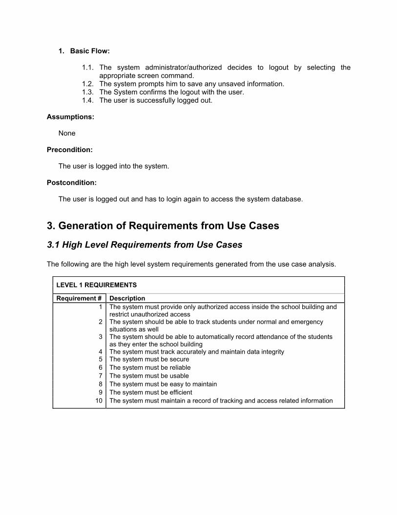
1. Basic Flow:
1.1. The system administrator/authorized decides to logout by selecting the appropriate screen command.
1.2. The system prompts him to save any unsaved information. 1.3. The System confirms the logout with the user. 1.4. The user is successfully logged out.
Assumptions:
None Precondition:
The user is logged into the system. Postcondition:
The user is logged out and has to login again to access the system database.
3. Generation of Requirements from Use Cases
3.1 High Level Requirements from Use Cases The following are the high level system requirements generated from the use case analysis.
LEVEL 1 REQUIREMENTS
Requirement # Description
1 The system must provide only authorized access inside the school building and restrict unauthorized access
2 The system should be able to track students under normal and emergency situations as well
3 The system should be able to automatically record attendance of the students as they enter the school building
4 The system must track accurately and maintain data integrity 5 The system must be secure
6 The system must be reliable
7 The system must be usable
8 The system must be easy to maintain
9 The system must be efficient
10 The system must maintain a record of tracking and access related information

3.2 Synthesis and break down of high level requirements The high level requirements are further synthesized and broken down into low-level requirements as listed in the table below.
LEVEL 2 REQUIREMENTS
Requirement # Description
FR1.1 Every student/staff shall have a permanent access id tag FR1.2 Every visitor shall get a day access id from the school entrance staff for access
to the school FR1.3 Permanent Id tags shall have the person’s name, photo, ID number
(student/staff ID number) and School name FR1.4 Day Id tags shall have the school name, person’s name and the
student/staff/visitor ID number FR1.5 There shall be two access controlled entrances: one for students and the other
for visitors and staff FR1.6 A day access ID shall be given Student/ staff who have forgotten their ID or lost
it FR1.7 The entrance door shall close after one revolution. The door needs to be one as
shown in the picture. (Refer appendix) FR1.8 The day access ID shall be valid only for a day FR1.9 Entrance to the school shall not be allowed from any other entrances from the
outside FR1.10 A student shall be able to get additional access to a restricted area upon
verification of the permission by the system administrator FR1.11 The student shall swipe the RFID tag near the reader to open the entrance door FR2.1 To get a day access Id, the student/staff/visitor needs to fill a form. The visitor
form shall have the name, address, purpose, kind of access required, staff reference name, phone number .The student form shall have the student name, ID number, teacher name, reason for the need for day ID tag, address, grade. The staff form shall have the name, address, class, reason for the need for day ID tag
FR2.2 In event of loss of the permanent ID tag, concerned student/ staff shall report it to the school authority, and get the day access id tag. The system admin shall try to track the id if lost in school. If found, it shall be returned to the user or else a permanent id shall be issued for daily access. The student/ staff needs to fill a form for this: name, address, student id, class, and teacher name, day he lost the id
FR2.3 The student/visitors/staff shall return their day access ids at the entrance to the entrance staff .In case the student/staff is permanently leaving the school, they can return their access IDs to the entrance staff.
FR2.4 The authorized user to the database shall be able to update, add, delete a record
FR2.5 The system database user shall need to logout of the database whenever done. The system shall prompt to save any unsaved information
FR2.6 Access to the GUI and the database shall be accessible only via a secure login provided by the systems administrator to the authorized users
FR2.7 The login id shall get locked if a user tries to enter a wrong username/ password more than thrice. In such a case only a systems administrator can reset the user password

FR3.1 When access is granted to a student, attendance for that student shall be recorded in the database and the entry shall be time stamped
FR3.2 For the first time login, the systems administrator shall provide a default password which the user shall need to change and update to a personalized one
FR3.3 The authorized user shall also have the ability to choose and print any report or record from the database
FR3.4 There shall be 4 kinds of reports that are generated: student/visitor/staff report, attendance report, tracking report, day report
FR4.1 The attendance report generated by the system shall be available to the teachers either as a printout or through a laptop connected in each classroom. The teacher can then verify the students in the list for her class with those physically present in the class. This is done for each class
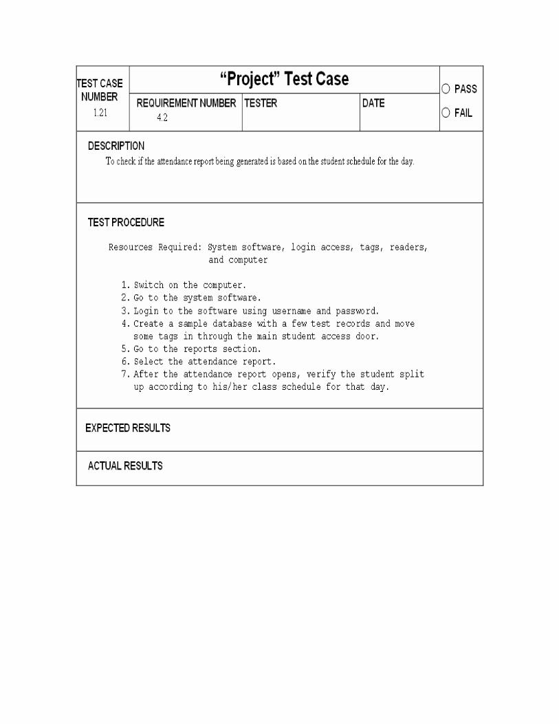
FR4.2 The system shall create an attendance report based on the student schedule for the day
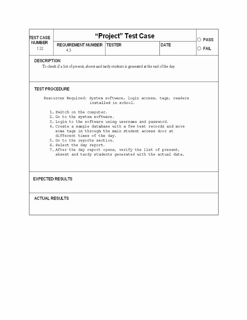
FR4.3 The system shall also upload a list of present, absent and tardy students FR5.1 All information concerned with the person entering the school shall be recorded
in the database and his entry and exit shall be time stamped FR6.1 Database shall be robust enough to be able to hold records of all students/staff
and visitors FR7.1 System shall be able to track students/ staff/ visitors on a timely basis. A timed
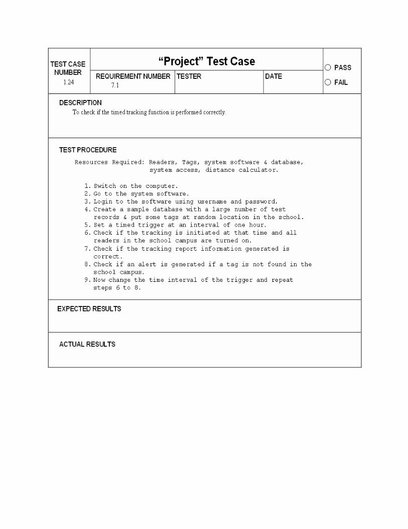
trigger shall initiate turning on of all the readers and gathering information about all students present in the reader coverage. If student not found, an alert is generated
FR7.2 Forced trigger shall be initiated when requested by a staff/parent/authority to track a particular student, a lost id or to track all students in case of an emergency
FR8.1
RFID readers shall be placed at the entrance and through out the school. The readers at the entrance and entrance of restricted areas will always be on whereas the readers on other locations inside school will be turned on only by the trigger initiation. This can be done by a system administrator or authorized user
FR9.1 Readers shall be able to read data from multiple tags at a time FR10.1 System shall be able to recover from unexpected crashes
3.4 Requirements arranged in a Tree Format The above synthesized requirements are arranged in a tree format based on the level of the requirements as shown in the figure. Level 1 requirement represent the system level requirements, sub system level requirements are stored at level 2 ad component level requirements are stored at level 3 and 4.


3.5 Requirements Traceability
Requirements Traceability Matrix
Requirement # Associated Use Case # Associated Activity diagram
FR1.1
Use Case 1
AD2
FR1.2 Use Case 2 AD2 FR1.3 Use Case 1 AD2 FR1.4 Use Case 2 AD2 FR1.5 Use Case 3 AD3 FR1.6 Use Case 2 AD2 FR1.7 Use Case 3, Use Case 4 AD3 FR1.8 Use Case 2 AD2 FR1.9 Use Case 3 AD3 FR1.10 Use Case 5 AD3 FR1.11 Use Case 3 AD3 FR2.1 Use Case 2 AD2 FR2.2 Use Case 2,Use Case 1,
Use Case 15 AD2,AD4
FR2.3 Use Case14 AD3 FR2.4 Use Case 10, Use Case 11,
Use Case 12 AD5
FR2.5 Use Case 16 AD1 FR2.6 Use Case 9 AD1 FR2.7 Use Case 9 AD1 FR3.1 Use Case 3 AD3 FR3.2 Use Case 6 AD1 FR3.3 Use Case 13 AD5 FR3.4 Use Case 13 AD5 FR4.1 Use Case 3 AD3 FR4.2 Use Case 3 AD3 FR4.3 Use Case 3 AD3 FR5.1 Use Case 3,Use Case 4 AD3 FR6.1 Use Case 10, Use Case 11,
Use Case 12 AD5
FR7.1 Use Case 7 AD4
FR7.2 Use Case 8 AD4 FR8.1 Use Case 7, Use Case 8 AD4 FR9.1 Use Case 7, Use Case 8 AD4
FR10.1 Use Case 12 AD5
4. High Level System Modeling and Analysis The simplified models of system behavior using activity diagrams and state chart diagrams are created.
4.1 System Behavior Diagram The system behavior is the different states of a system element and the sequences of tasks making up activities governed by conditional logic and flows driven by internal processing. System behavior for the Smart school Id System has been modeled using Activity and State Chart Diagrams. 4.1.1 Activity Diagrams: The purpose of the activity diagram is to model the procedural flow of actions that are part of a larger activity. Activity diagrams can also be used independently of use cases for modeling a business-level or system – level function representing multiple use cases in one activity diagram. The Following 5 Activity Diagrams were identified for the Smart School ID system.

Activity Diagram 1 Login, request a login & logout

Activity Diagram 2: Issue a new permanent /day access ID or return an access ID

Activity Diagram 3: Student Attendance Reconciliation, Visitor /staff access to entrance.

Activity Diagram 4: Tracking in normal and special situations

Activity Diagram 5: Database Access, update and print/generate report
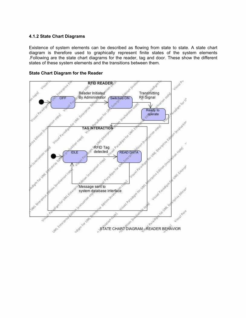
4.1.2 State Chart Diagrams
Existence of system elements can be described as flowing from state to state. A state chart diagram is therefore used to graphically represent finite states of the system elements .Following are the state chart diagrams for the reader, tag and door. These show the different states of these system elements and the transitions between them. State Chart Diagram for the Reader

State Chart Diagram for the Tag
State Chart Diagram for the Door

5. System Specifications The above specified requirements are realized in qualitative and quantitative terms known as specifications. They are shown below in the table.
COMPONENT REQUIREMENTS SPECIFICATIONS
Requirement # Description Attribute Function/Performance
Tag
CR1 Those Rfid tags should be used which would be capable of wireless mid range(atleast 10-30 feet) radio-frequency communications
Tags Semi-Passive
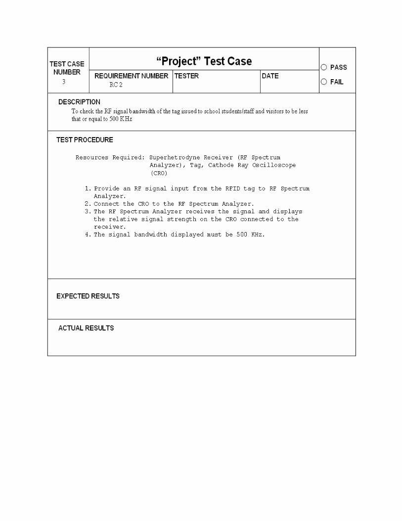
CR2 The tag RF signal bandwidth shall be less that or equal to 500 KHz
RF Signal Bandwidth
500Khz
CR3 The tag should be able to communicate with the reader placed at a minimum distance of 15 feet
Carrier Frequency
13.56MHZ (UHF)
CR4 The background noise of the transmission medium should not interfere with the transmitted signal
S/N Ratio 13.5db
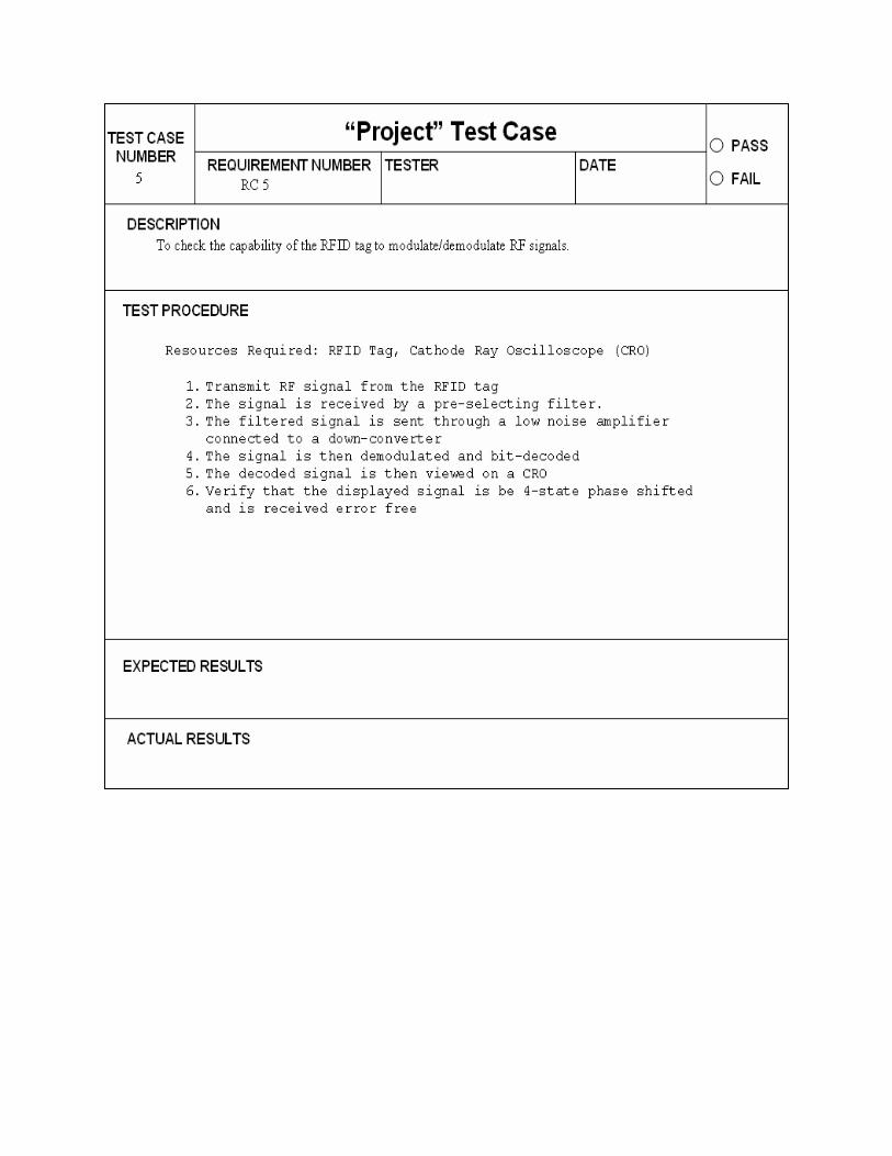
CR5 The tag shall be capable of modulating/demodulating RF signals.
Signal Processing
using PSK 4 (4 state phase shift keying)
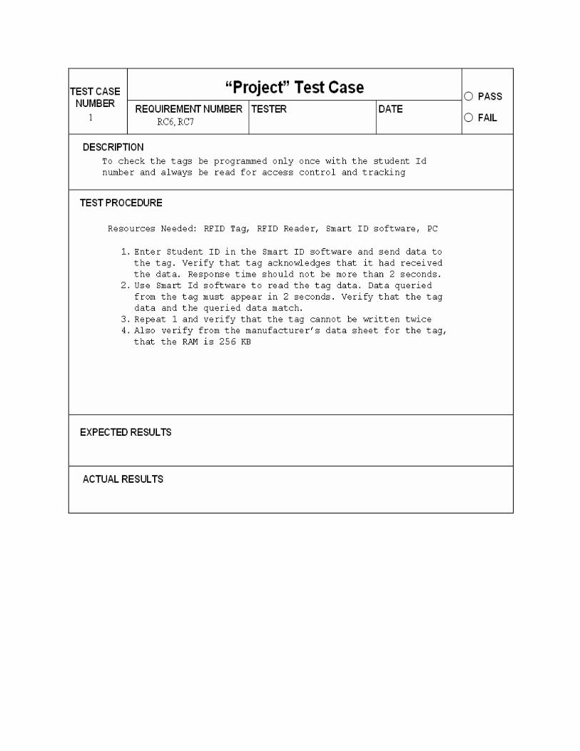
CR6 The tag shall be capable of being programmed with a unique ID number
Microcontroller memory
1Mb and 512KB RAM
CR7 The tags shall be programmed only once with the student Id number and always be read for access control and tracking purposes
Read/write WORM tags
CR8 The clock frequency of the microcontroller shall be compatible with RF transponders signal processing speed
Microcontroller memory
CR9 The tag shall atleast have a life span of 5 years
power consumption
<=35mW
CR10 The microcontroller shall trigger a flash LED indicating a low battery voltage insufficient to operate the Tag.
Battery Output voltage 4.6 and 5 V(regulated)
CR11 Weight <3oz
The tag should be light weight and small in size Size 2.1"X3.4"X1"
CR12 The tag should be able to handle the interference caused by various factors (electromagnetic interference, lab equipment, mud snow, metal) inside the school
Operating Frequency
UHF(about ~902-928Mhz)

CR13
The antenna design shall be capable of sending and receiving RF signals in a hemispherical pattern
Coverage area
Hemispherical
CR14 The antenna shall be small enough to fit in the Tag enclosure
Size 0.3 inch
Reader
CR15 The reader should indicate a low voltage supply
Reader Power Indicator
Unregulated 12V DC
CR16 The tag reader should read the data from the tag regardless of its orientation
Antenna 4 port (Circular or linear polarization)
CR17 Tag reader should be able to detect and read data from a tag which is about 5 m away from the reader
Operating Frequency
UHF(about ~902-928Mhz)
CR18 The readers should be able to get connected wirelessly or using cables to form a network
Connection to Network
Ethernet, 802.11G or 802.3 wired
CR19 The readers should perform well under extreme temperatures
Operating Temperature
:-32F to 122F
CR20 Tag reader should be robust ,splash proof and rugged
Protection Type
IP 54, IP 67
CR21 The reader installed at the entrances of the restricted areas and main school entrance should read the tags only close to it and not outside the door
Tag type and special enclosure
Portal readers work in conjunction with presence detectors and an RF reflector surface such as metal mesh. The metal mesh which surrounds the doorway prevents the transmission from adjoining doors being read in error. Reader Type: IF5
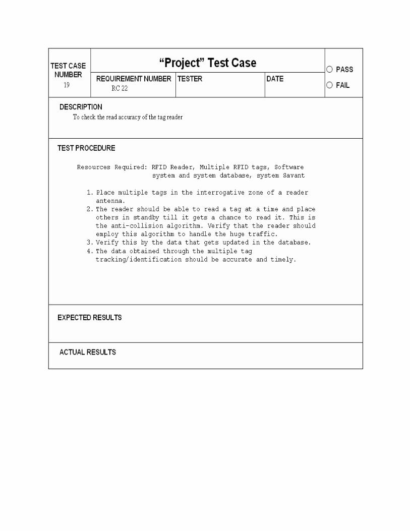
CR22 The reader must be able to read multiple tags at the same time, maintaining data integrity and accuracy
Read Accuracy
Anti-collision Algorithm
CR23 The reader should read the data accurately
Read Accuracy
No False Reads
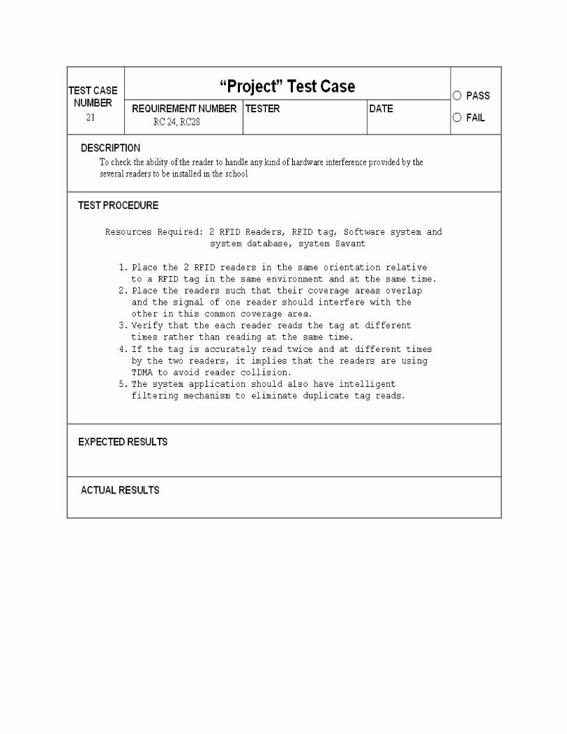
CR24 The reader shall handle any kind of hardware interference
Read Accuracy
reader collision also using TDMA
CR25 The reader should be compatible with the windows OS
Reader Compatibility with OS
Windows OS
DB
CR26 The DBMS should be robust and record data with minimum latency
response time
45 sec
CR27 There should be no duplicate data in the records
Data
Duplication Theorem
CR28 The readers should identify the accurate location when tracking
Location Distance Calculator

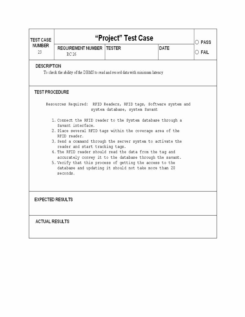
6. Component-System Testing, Verification and Validation Developed procedures of system test, verification and validation. The system was tested for a sample school layout that has been introduced as Layout Figure A in the system introduction section.
6.1 Primary Verification and Validation Plan
After requirements have been developed, one or more verification requirements should be developed for each requirement. Verification requirements determine whether or not a requirement has been achieved. The test procedures are listed below.


6.2 Verification Traceability Matrix
After developing the Verification Plan, it is important to verify that all high-level requirements will be verified through execution of the plan. The High-level Requirements Traceability Matrix, which is shown in the table below, maps the verification methods with each high-level requirement. This ensures that the Verification Plan does provide verification methods for all high-level requirements and can, therefore, be considered complete.
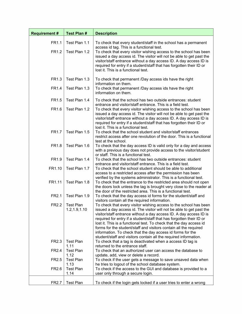
Requirement # Test Plan # Description
FR1.1
Test Plan 1.1
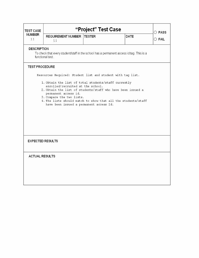
To check that every student/staff in the school has a permanent access id tag. This is a functional test.
FR1.2
Test Plan 1.2
To check that every visitor wishing access to the school has been issued a day access id. The visitor will not be able to get past the visitor/staff entrance without a day access ID. A day access ID is required for entry if a student/staff that has forgotten their ID or lost it. This is a functional test.
FR1.3
Test Plan 1.3
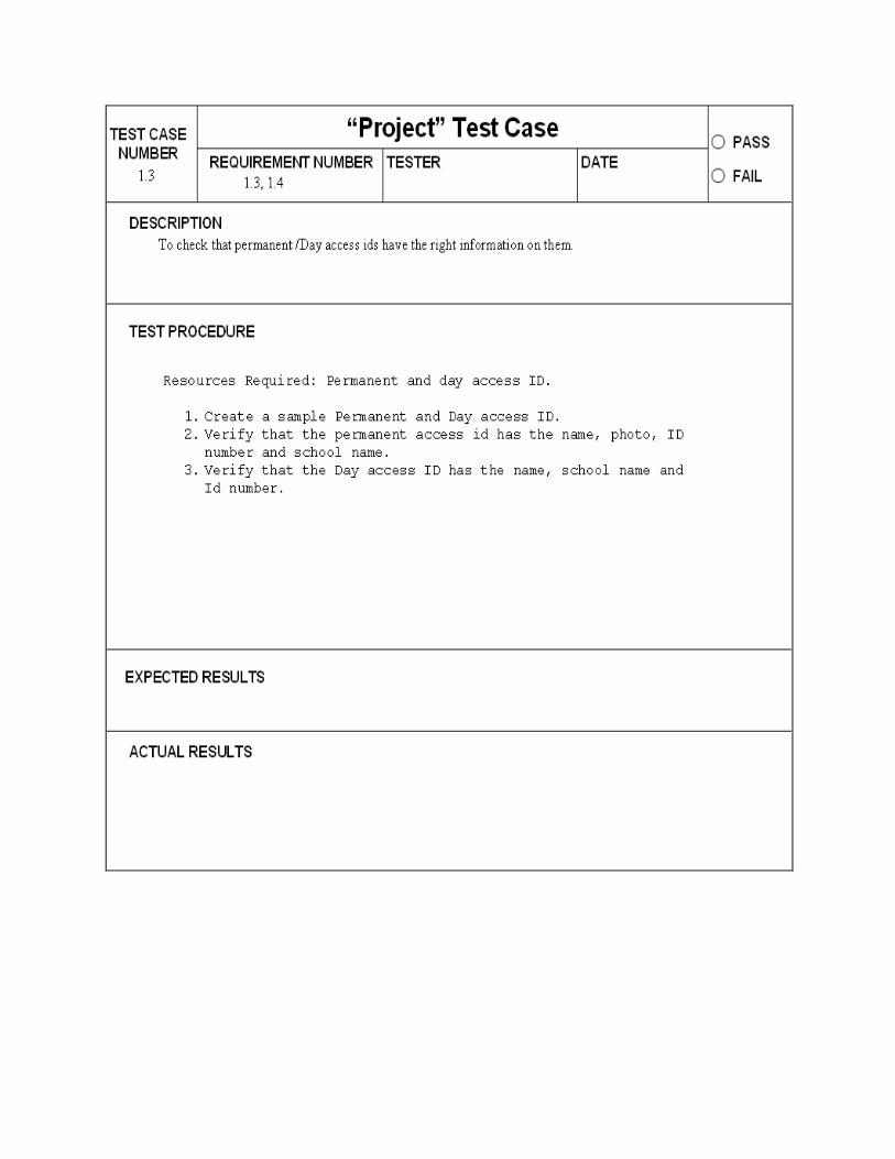
To check that permanent /Day access ids have the right information on them.
FR1.4 Test Plan 1.3 To check that permanent /Day access ids have the right information on them.
FR1.5 Test Plan 1.4 To check that the school has two outside entrances: student entrance and visitor/staff entrance. This is a field test.
FR1.6 Test Plan 1.2 To check that every visitor wishing access to the school has been issued a day access id. The visitor will not be able to get past the visitor/staff entrance without a day access ID. A day access ID is required for entry if a student/staff that has forgotten their ID or lost it. This is a functional test.
FR1.7 Test Plan 1.5 To check that the school student and visitor/staff entrances restrict access after one revolution of the door. This is a functional test at the school.
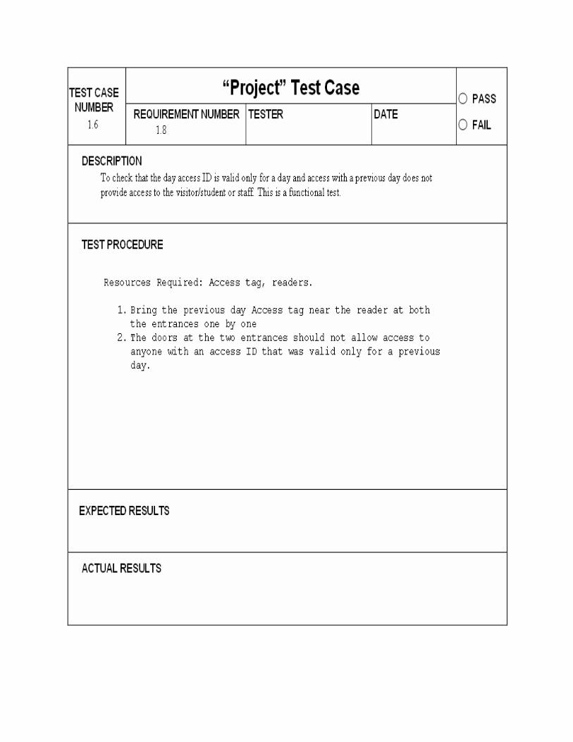
FR1.8 Test Plan 1.6 To check that the day access ID is valid only for a day and access with a previous day does not provide access to the visitor/student or staff. This is a functional test.
FR1.9 Test Plan 1.4 To check that the school has two outside entrances: student entrance and visitor/staff entrance. This is a field test.
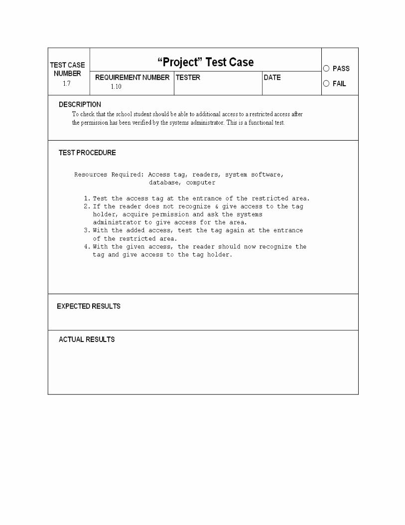
FR1.10 Test Plan 1.7 To check that the school student should be able to additional access to a restricted access after the permission has been verified by the systems administrator. This is a functional test.
FR1.11 Test Plan 1.8 To check that the entrance to the restricted area should not open the doors lock unless the tag is brought very close to the reader at the door of the restricted area. This is a functional test.
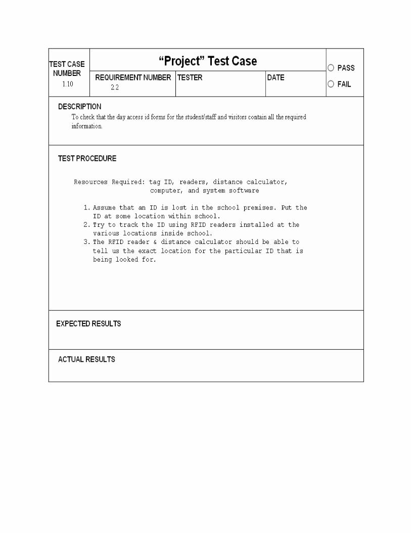
FR2.1 Test Plan 1.9 To check that the day access id forms for the student/staff and visitors contain all the required information.
FR2.2 Test Plan 1.2,1.9,1.10
To check that every visitor wishing access to the school has been issued a day access id. The visitor will not be able to get past the visitor/staff entrance without a day access ID. A day access ID is required for entry if a student/staff that has forgotten their ID or lost it. This is a functional test. To check that the day access id forms for the student/staff and visitors contain all the required information. To check that the day access id forms for the student/staff and visitors contain all the required information.
FR2.3 Test Plan 1.11
To check that a tag is deactivated when a access ID tag is returned to the entrance staff.
FR2.4 Test Plan 1.12
To check that an authorized user can access the database to update, add, view or delete a record.
FR2.5 Test Plan 1.13
To check if the user gets a message to save unsaved data when he tries to logout of the school database system.
FR2.6 Test Plan 1.14
To check if the access to the GUI and database is provided to a user only through a secure login.
FR2.7
Test Plan
To check if the login gets locked if a user tries to enter a wrong
1.15 username and password more than thrice.
FR3.1 Test Plan 1.16
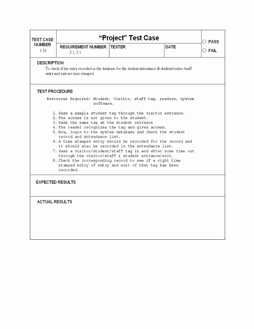
To check if the entry recorded in the database for the student attendance & student/visitor /staff entry and exit are time stamped.
FR3.2 Test Plan 1.17
To check if the authorized user is able to change the default password provided by the systems administrator.
FR3.3 Test Plan 1.18
To check if the authorized user has the ability to print any report from the database.
FR3.4
Test Plan 1.19
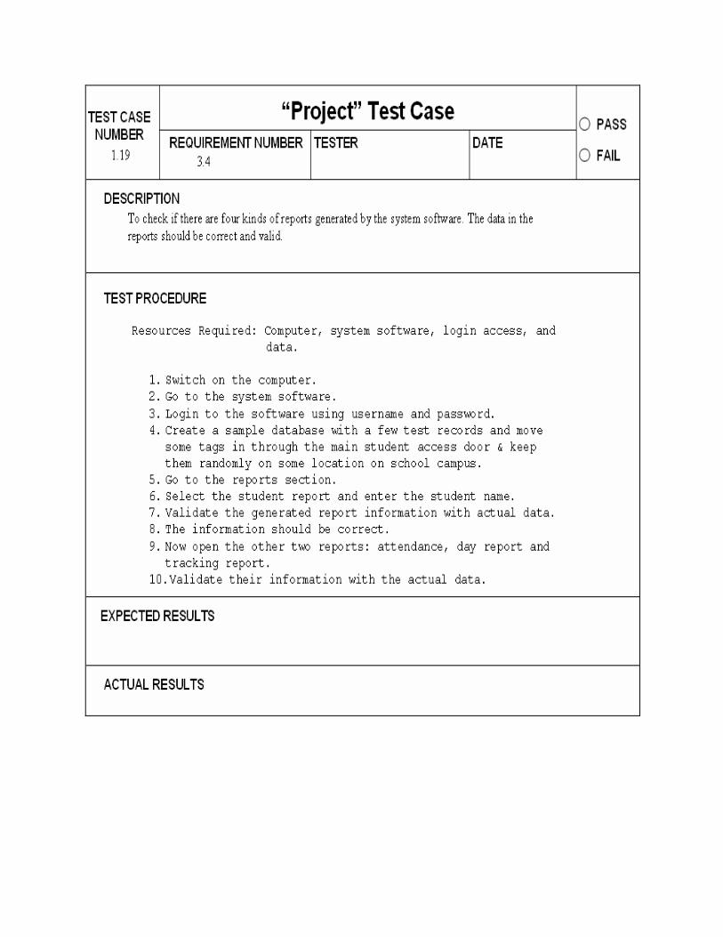
To check if there are four kinds of reports generated by the system software. The data in the reports should be correct and valid.
FR4.1 Test Plan 1.20
To check if you are able to print the attendance report that is being generated by the system. Also test if the attendance report is being sent to all the teacher laptops for each classroom. Also Check for data consistency between the two.
FR4.2 Test Plan 1.21
To check if the attendance report being generated is based on the student schedule for the day.
FR4.3 Test Plan 1.22
To check if a list of present, absent and tardy students is generated at the end of the day.
FR5.1 Test Plan 1.16
To check if the entry recorded in the database for the student attendance & student/visitor /staff entry and exit are time stamped.
FR6.1 Test Plan 1.23
To check if the database is robust enough to hold a large number of records.
FR7.1 Test Plan 1.24
To check if the timed tracking functions is performed correctly.
FR7.2 Test Plan 1.25
To check if the forced tracking functions is performed correctly.
FR8.1 Test Plan 1.26
To check if the readers can be stopped and initiated at any time by the systems administrator.
FR9.1 TC19
FR10.1 Test Plan 1.27
To check if a back up database has been created to ensure that data does not lose on a system crash.
Component Requirement
Specification Attribute
Specification desired performance Test Case number
CR1
Tags
Semi-Passive
TC2
CR2 RF Signal Bandwidth 500Khz TC3
CR3 Carrier Frequency 13.56MHZ (UHF) TC2
CR4 S/N Ratio 13.5db TC4
CR5 Signal Processing using PSK 4 (4 state phase shift keying)
TC5
CR6 Microcontroller memory
1Mb and 512KB RAM T16
CR7 Read/write WORM tags TC1
CR8 Microcontroller clock frequency
TC6
CR9 power consumption <=35mW TC7
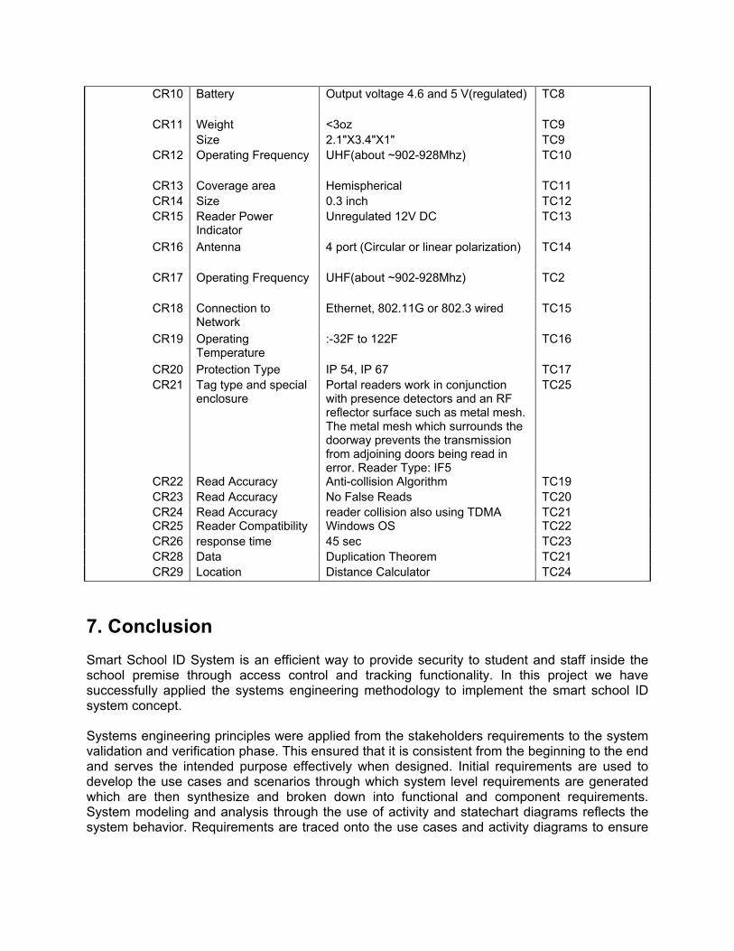
CR10 Battery Output voltage 4.6 and 5 V(regulated) TC8
CR11 Weight <3oz TC9
Size 2.1"X3.4"X1" TC9
CR12 Operating Frequency UHF(about ~902-928Mhz) TC10
CR13 Coverage area Hemispherical TC11
CR14 Size 0.3 inch TC12
CR15 Reader Power Indicator
Unregulated 12V DC TC13
CR16 Antenna 4 port (Circular or linear polarization) TC14
CR17 Operating Frequency UHF(about ~902-928Mhz) TC2
CR18 Connection to Network
Ethernet, 802.11G or 802.3 wired TC15
CR19 Operating Temperature
:-32F to 122F TC16
CR20 Protection Type IP 54, IP 67 TC17
CR21 Tag type and special enclosure
Portal readers work in conjunction with presence detectors and an RF reflector surface such as metal mesh. The metal mesh which surrounds the doorway prevents the transmission from adjoining doors being read in error. Reader Type: IF5
TC25
CR22 Read Accuracy Anti-collision Algorithm TC19
CR23 Read Accuracy No False Reads TC20
CR24 Read Accuracy reader collision also using TDMA TC21 CR25 Reader Compatibility Windows OS TC22
CR26 response time 45 sec TC23
CR28 Data Duplication Theorem TC21
CR29 Location Distance Calculator TC24
7. Conclusion Smart School ID System is an efficient way to provide security to student and staff inside the school premise through access control and tracking functionality. In this project we have successfully applied the systems engineering methodology to implement the smart school ID system concept. Systems engineering principles were applied from the stakeholders requirements to the system validation and verification phase. This ensured that it is consistent from the beginning to the end and serves the intended purpose effectively when designed. Initial requirements are used to develop the use cases and scenarios through which system level requirements are generated which are then synthesize and broken down into functional and component requirements. System modeling and analysis through the use of activity and statechart diagrams reflects the system behavior. Requirements are traced onto the use cases and activity diagrams to ensure

that the use cases and system behavior is reflected in the requirements. Qualitative and quantitative requirements are allocated attributes and assigned parameters. The two important parts of systems approach are system validation and system verification. Validation ensures that you build the right product whereas verifications ensure that we are building the product right. A verification plan is therefore proposed to test all the functional requirements and specifications. The tests defined in the verification plan are also traced back to the requirements. If the system passes all the tests it can be assured that the final system after actual implementation and deployment will meet the customer requirements.
8. References
• Mark Austin, ENSE 623 System Validation and Verification Lecture Notes, Fall 2006
• Mark Austin, Information-Centric Systems Engineering, Fall 2005
• Mark Austin, Systems Engineering Validation and Verification, Reading for ENSE 623/ ENPM 643
• Klaus Kinkenzeller, RFID Handbook, Second Edition
• Sandip Lahiri, RFID Sourcebook
• The Unified Modeling Language User Guide, Grady Booch