systems biology microscopy workshopmicroscopy workshop · mcgill university life sciencesmcgill...
TRANSCRIPT

McGill University Life SciencesMcGill University Life SciencesComplex Imaging Facility
Systems BiologyMicroscopy WorkshopMicroscopy Workshop
Tuesday December 7th, 2010
Si l L T itt d Li htSimple Lenses, Transmitted Light Optical Train, Köhler Illuminationp ,

What Does a Microscope Need To Do?
Three things need to be accomplished:
1. M A G N I F YProduce a magnified image of the specimen.g g p
2. C O N T R A S TRender the details within the specimen visible to the imagingRender the details within the specimen visible to the imaging device: e.g. eye, camera, photomultiplier tube
3. R E S O L V EDistinguish between objects or features within the specimen.
All three things need to be accomplished.
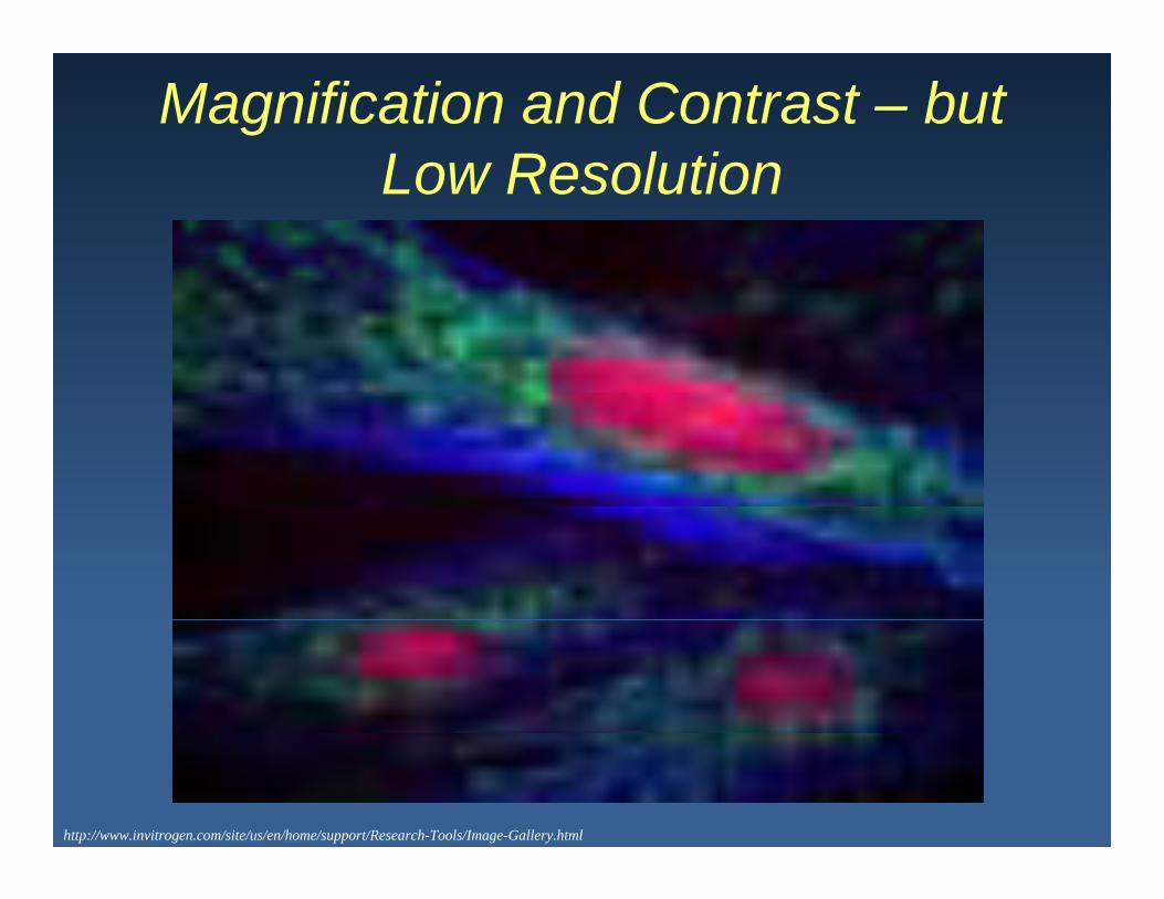
Magnification and Contrast – but Low ResolutionLow Resolution
http://www.invitrogen.com/site/us/en/home/support/Research-Tools/Image-Gallery.html

Magnification and Resolutionbut Low Contrast– but Low Contrast
http://www.invitrogen.com/site/us/en/home/support/Research-Tools/Image-Gallery.html
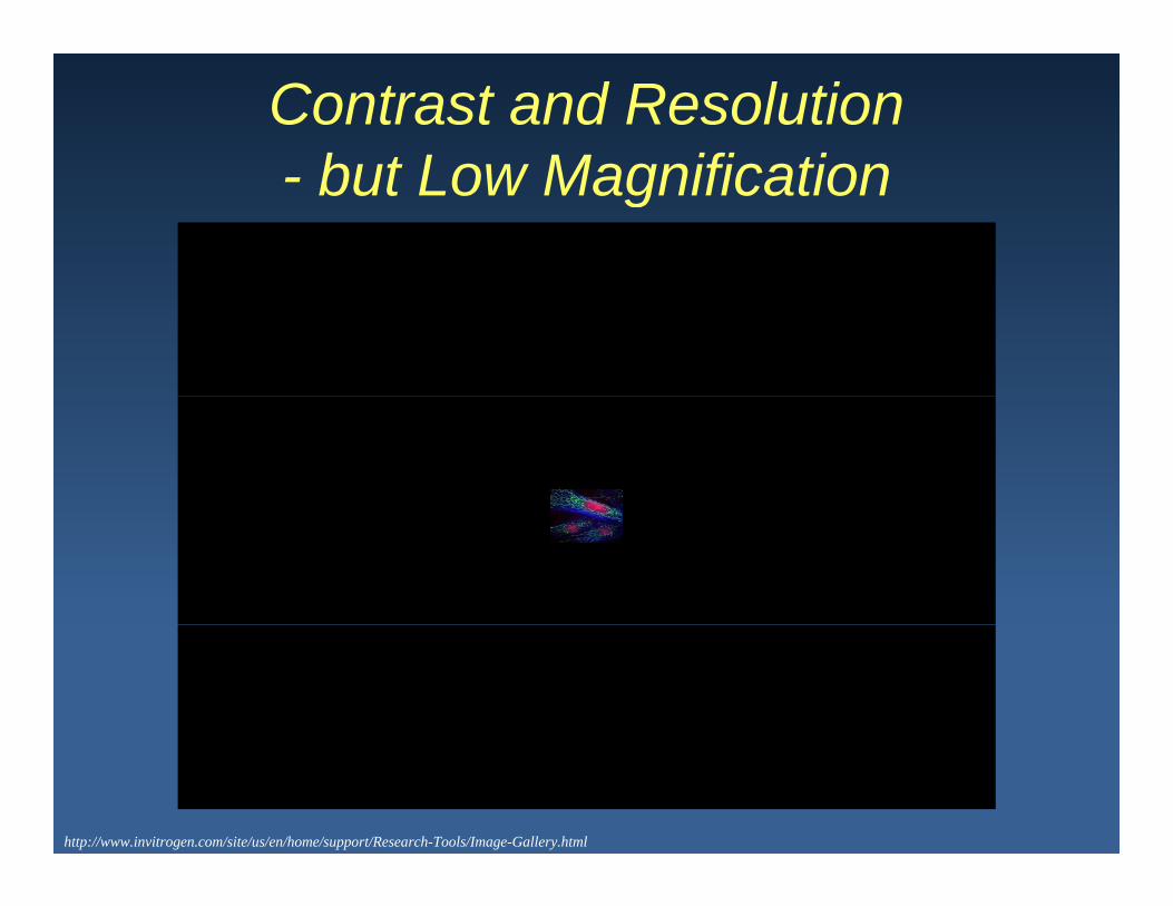
Contrast and Resolution but Low Magnification- but Low Magnification
http://www.invitrogen.com/site/us/en/home/support/Research-Tools/Image-Gallery.html

Magnification, Contrast, Resolution
http://www.invitrogen.com/site/us/en/home/support/Research-Tools/Image-Gallery.html

MagnificationMagnify: Produce a magnified image of the specimen.
Magnification = Mag Objective lens x Mag Eyepiece LensMagnification = Mag. Objective lens x Mag. Eyepiece Lens20x lens X 10x eyepiece = 200x magnification60x lens X 10x eyepiece = 600x magnification60x lens X 10x eyepiece = 600x magnification
http://media.thestar.topscms.com/images/3a/7d/fe044496470cbcd585a2307b6ab0.jpeg
http://www.astrographics.com/GalleryPrints/Display/GP2129.jpghttp://www5.pbrc.hawaii.edu/microangela/mhflyo.jpg

Simple Biconvex Lens
Modified by Aleks Spurmanis from http://www.olympusmicro.com/primer/anatomy/magnification.html

Simple Biconvex Lens
Focal Points: R F l P i t (F’) P i t h li ht i f i fi itRear Focal Point (F’): Point where light coming from an infinite distance is focused to a fine point.
Modified by Aleks Spurmanis from http://www.olympusmicro.com/primer/anatomy/magnification.html

Simple Biconvex Lens
Focal Points: R F l P i t (F’) P i t h li ht i f i fi itRear Focal Point (F’): Point where light coming from an infinite distance is focused to a fine point.Front Focal Point (F’): Point where light rays collected from a i l i t d t i t ll lsingle point source spread out into parallel rays.
Modified by Aleks Spurmanis from http://www.olympusmicro.com/primer/anatomy/magnification.html

Simple Biconvex Lens
Focal Points: R F l P i t (F’) P i t h li ht i f i fi itRear Focal Point (F’): Point where light coming from an infinite distance is focused to a fine point.Front Focal Point (F): Point where light rays collected from a single
i t d t i t ll lpoint source spread out into parallel rays.Optical Axis: Imaginary line through center of lens and focal points.
Modified by Aleks Spurmanis from http://www.olympusmicro.com/primer/anatomy/magnification.html

Simple Biconvex Lens
Focal Points: R F l P i t (F’) P i t h li ht i f i fi itRear Focal Point (F’): Point where light coming from an infinite distance is focused to a fine point.Front Focal Point (F’): Point where light rays collected from a i l i t d t i t ll lsingle point source spread out into parallel rays.
Optical Axis: Imaginary line through center of lens and focal points.Focal Length: Distance along the optical axis between the center of the
lens and either focal point.
Modified by Aleks Spurmanis from http://www.olympusmicro.com/primer/anatomy/magnification.html
Simple Biconvex Lens
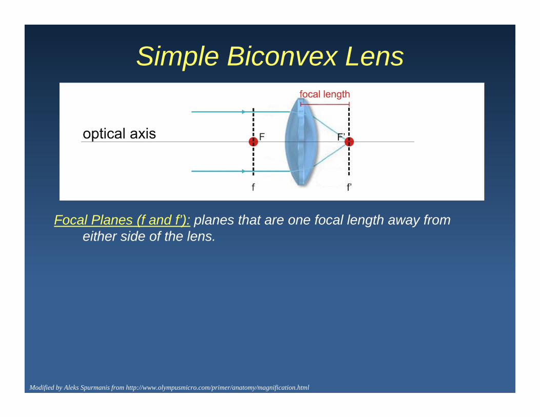
Focal Planes (f and f’): planes that are one focal length away from either side of the lenseither side of the lens.
Modified by Aleks Spurmanis from http://www.olympusmicro.com/primer/anatomy/magnification.html

Simple Biconvex Lens
Focal Planes (f and f’): planes that are one focal length away from either side of the lenseither side of the lens.
2F Points: points along the optical axis that lie at 2x the focal length.
Modified by Aleks Spurmanis from http://www.olympusmicro.com/primer/anatomy/magnification.html

Simple Biconvex Lens
Focal Planes (f and f’): planes that are one focal length away from either side of the lenseither side of the lens.
2F Points: points along the optical axis that lie at 2x the focal length.2f Planes: Planes that are 2 focal lengths away from either side of the
llens.
Modified by Aleks Spurmanis from http://www.olympusmicro.com/primer/anatomy/magnification.html

Simple Biconvex Lens
If an object is at 2F in front of the lens then an intermediate image is formed at 2F’ behind the lens and itintermediate image is formed at 2F’ behind the lens and it is a real image. This image is formed at the intermediate image plane.
Real Images:1. Need to cross through a focal point2 Are inverted
IntermediateImage
Intermediate2. Are inverted3. Can be projected onto a surface, captured on film or
a digital detector. Modified by Aleks Spurmanis from http://www.olympusmicro.com/primer/anatomy/magnification.html
IntermediateImagePlane
Simple Biconvex Lens
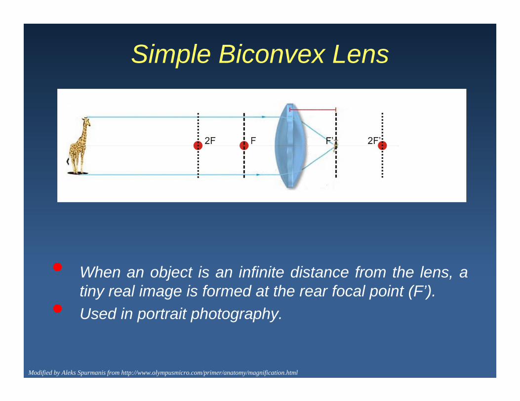
• When an object is an infinite distance from the lens, aWhen an object is an infinite distance from the lens, atiny real image is formed at the rear focal point (F’).
• Used in portrait photography.
Modified by Aleks Spurmanis from http://www.olympusmicro.com/primer/anatomy/magnification.html

Magnification and LensesObject at Infinity – Scenic Photography
Ray Diagram
Object at Infinity Scenic Photography
Real image formed at focal plane.
Focal Point
http://www.olympusmicro.com/primer/anatomy/magnification.html
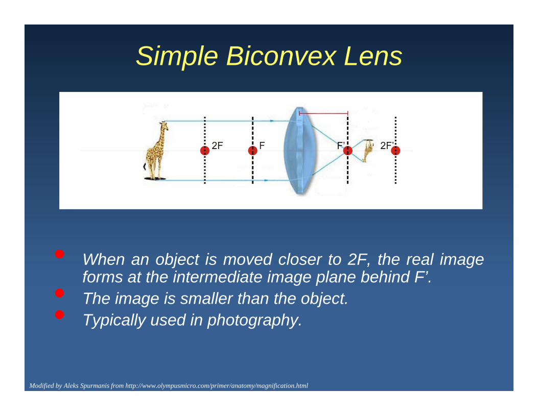
Simple Biconvex Lens
• When an object is moved closer to 2F, the real imageforms at the intermediate image plane behind F’.• The image is smaller than the object.• Typically used in photography.
Modified by Aleks Spurmanis from http://www.olympusmicro.com/primer/anatomy/magnification.html
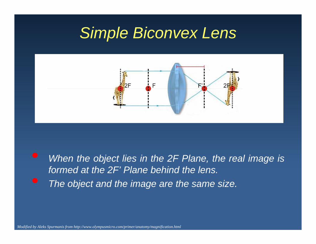
Simple Biconvex Lens
• When the object lies in the 2F Plane, the real image isformed at the 2F’ Plane behind the lensformed at the 2F’ Plane behind the lens.
• The object and the image are the same size.
Modified by Aleks Spurmanis from http://www.olympusmicro.com/primer/anatomy/magnification.html
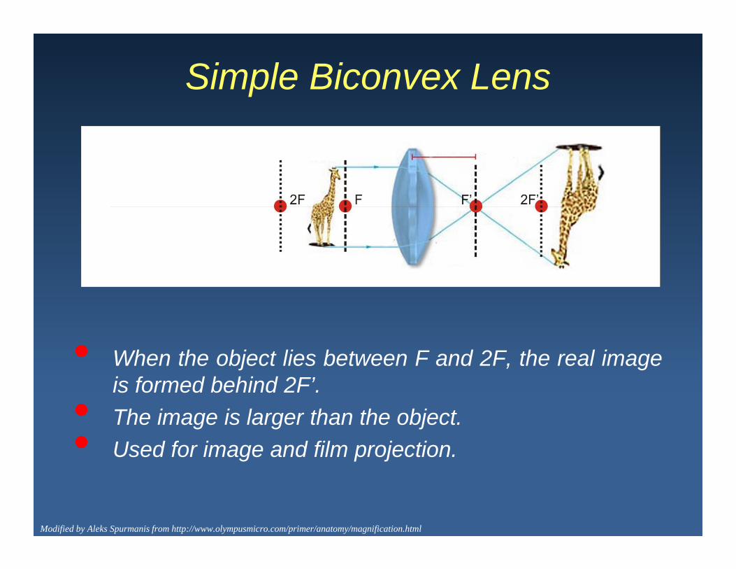
Simple Biconvex Lens
• When the object lies between F and 2F, the real imageis formed behind 2F’.is formed behind 2F .
• The image is larger than the object.• Used for image and film projection.
Modified by Aleks Spurmanis from http://www.olympusmicro.com/primer/anatomy/magnification.html

Simple Biconvex Lens
What happens when the object is placed at the front focal plane?
Modified by Aleks Spurmanis from http://www.olympusmicro.com/primer/anatomy/magnification.html

Simple Biconvex Lens
What happens when the object is placed at the front focal plane?
No real image can be formed behind the lens since light rays fromevery point in the object plane leave the lens in parallel.
Modified by Aleks Spurmanis from http://www.olympusmicro.com/primer/anatomy/magnification.html
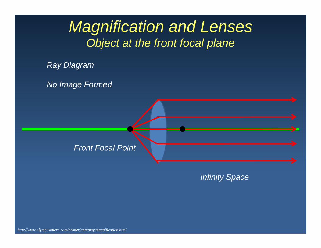
Magnification and LensesObject at the front focal plane
Ray Diagram
Object at the front focal plane
No Image Formed
Front Focal Point
Infinity Space
http://www.olympusmicro.com/primer/anatomy/magnification.html

Simple Biconvex Lens
What happens when the object is placed closer than the focal point?
A virtual image is perceived behind the object when looking throughthe lens.
Virtual Images:1. Image is upright2. Image can’t be projected onto a surface, film or digital detectors.3. Image appears on same side of the lens as the object.
Modified by Aleks Spurmanis from http://www.olympusmicro.com/primer/anatomy/magnification.html

Magnifying Glass or a Mirror
http://www.olympusmicro.com/primer/anatomy/magnification.html

Two Lens Systems
Modern microscopes use a two lens system with the objective lens being one and the tube lens being the second
http://micro.magnet.fsu.edu/primer/java/components/twolenssystem/index.html
being one and the tube lens being the second.

Finite vs Infinity Corrected Optics
Davidson M.W and Abramowitz M., Optical Microscopy, review article, Olympus America Inc.
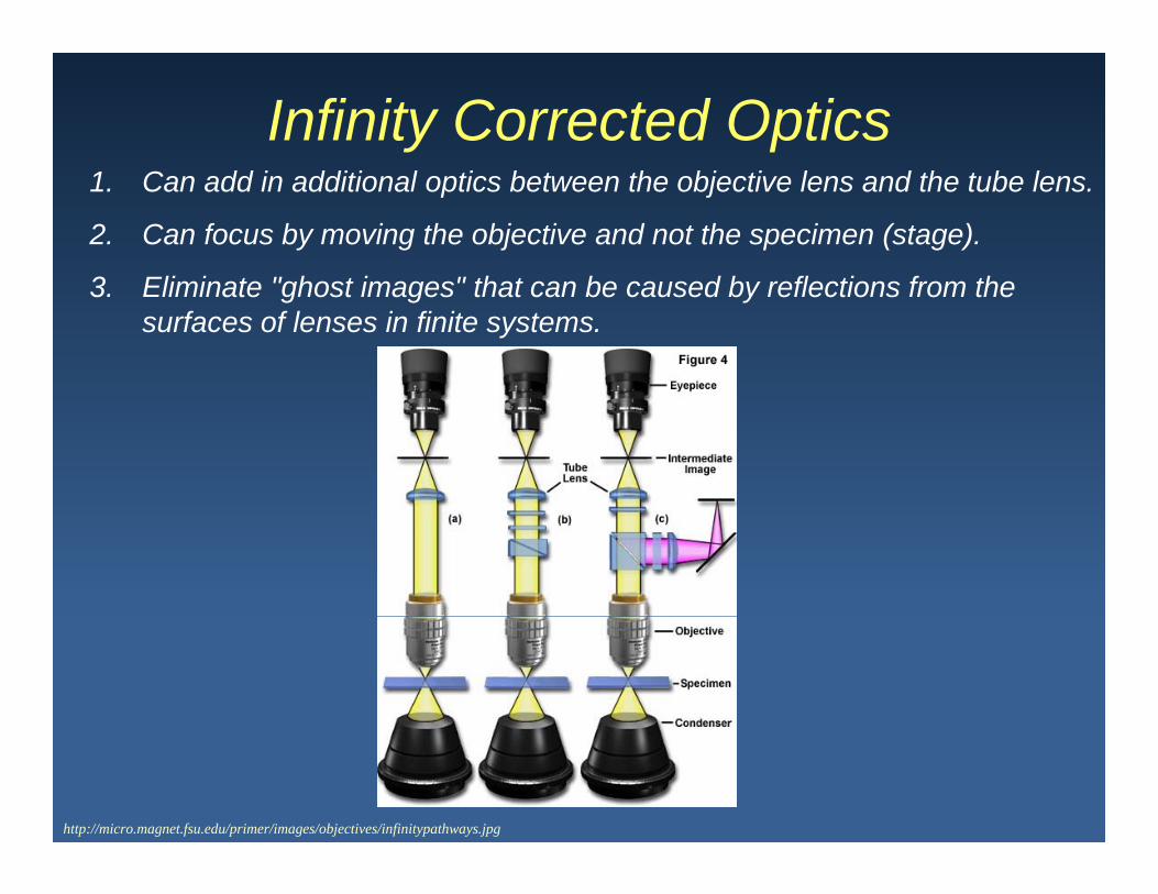
Infinity Corrected Optics1. Can add in additional optics between the objective lens and the tube lens.
2. Can focus by moving the objective and not the specimen (stage).
3 Eli i t " h t i " th t b d b fl ti f th3. Eliminate "ghost images" that can be caused by reflections from the surfaces of lenses in finite systems.
http://micro.magnet.fsu.edu/primer/images/objectives/infinitypathways.jpg

Abbe’s Theory of Image FormationErnst Karl Abbe (1840-1905)
A German physicist who created the firstA German physicist who created the first mathematical formulation for microscope design. Prior to his work microscopes components and design was done primarily by trial and error.design was done primarily by trial and error.
He worked with Carl Zeiss to develop early scientific research microscopes.p
He derived the formula for the theoretical resolution of the microscope.
Depends on the wavelength of light, numerical aperture of the plens, refractive index of the imaging medium.
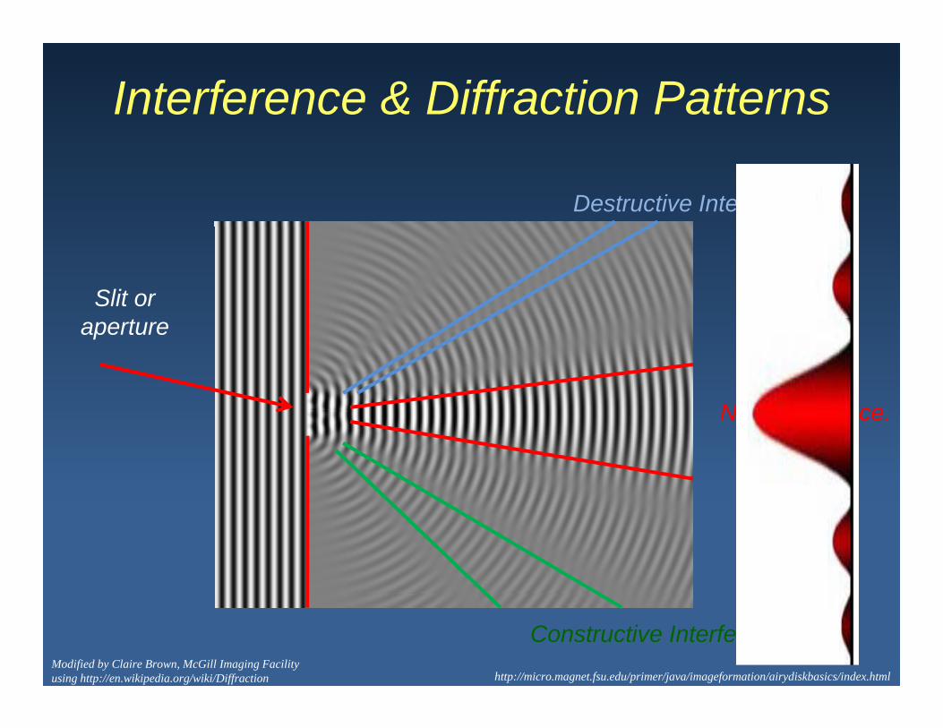
Interference & Diffraction Patterns
Destructive Interference
Slit ort
No Interference
aperture
No Interference.
Constructive Interferencehttp://micro.magnet.fsu.edu/primer/java/imageformation/airydiskbasics/index.html
Modified by Claire Brown, McGill Imaging Facility using http://en.wikipedia.org/wiki/Diffraction

Interference & Diffraction Patterns
DestructiveInterference
1st orderDefracted
2nd orderDefracted
http://micro.magnet.fsu.edu/primer/lightandcolor/diffractionintro.html
Zero Order not Defracted
DefractedConstructiveInterference
DefractedConstructiveInterference

Imaging a Line GratingDiffraction pattern depends on colour of light.act o patte depe ds o co ou o g t
Larger spacing with longer wavelength.
Red light is diffracted more than blue light
http://www.olympusmicro.com/primer/java/imageformation/gratingdiffraction/index.html

White Light Diffraction•• See a spectrum of light when white light is diffracted by a grid
pattern.
• Blue less diffraction than red.Blue less diffraction than red.
• Higher order diffraction is due to smaller features in the image.
• Smaller features cause a bigger difference in the amount of diffraction between the different colours.
Increasing Diffraction
http://www.olympusmicro.com/primer/anatomy/image.html

Imaging a Line GratingDiffraction Pattern depends on line spacing.
Closer lines are together more diffraction.
http://www.olympusmicro.com/primer/java/imageformation/gratingdiffraction/index.htmlDiffraction Grating Tutorial

Imaging a Line GratingDiffraction Pattern depends on line spacing.
Closer lines are together more diffraction.g
http://www.olympusmicro.com/primer/java/imageformation/diffractionpaths/index.htmlDiffraction Paths Tutorial

Imaging a Line Grating
N G ti 10 L 40 L 60 LNo Grating 10x Lens 40x Lens 60x Lens
Diffraction seen at the back aperture of the objective lens.
http://www.olympusmicro.com/primer/anatomy/image.html

Imaging Complex Patterns
Vertical Lines Horizontal LinesHorizontal Lines
http://www.olympusmicro.com/primer/anatomy/image.html
Complex Patterns Tutorial

Complex Diffraction PatternsInterference of two circular waves
Interference: Addition of two or more waves resulting in a new wave form.
IncreasingIncreasingWavelength Interference
Simulation
Increasing distance between wave centers.http://en.wikipedia.org/wiki/Interference

Microscope Image
Diffraction patterns from light interacting with all aspect of the specimen.
Large Features
Small Features
Random Features
Ordered FeaturesClaire Brown, McGill Imaging Facility

Upright Microscope
Illumination system below the ispecimen
Objective lenses above the specimen
Fixed location of objectives stage moves.
Good for tissue or small organism imaging with water dipping lenses.
http://micro.magnet.fsu.edu/primer/anatomy/components/componentsfigure1.jpg

Upright Transmitted Light PathwayOptical TrainOptical Train
1) Light from the halogen lamp is f d b ll t l dfocused by collector lenses and sent to the condenser.
http://micro.magnet.fsu.edu/primer/lightandcolor/lensesintro.html
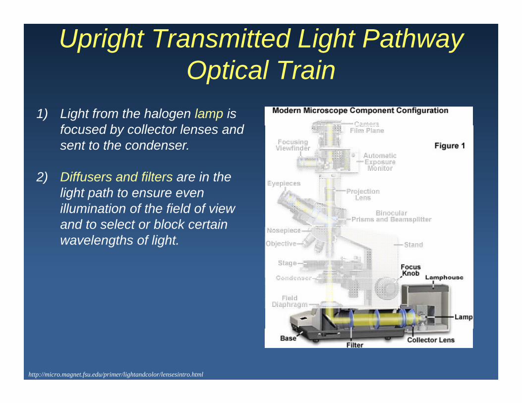
Upright Transmitted Light PathwayOptical TrainOptical Train
1) Light from the halogen lamp is f d b ll t l dfocused by collector lenses and sent to the condenser.
2) Diffusers and filters are in the2) Diffusers and filters are in the light path to ensure even illumination of the field of view and to select or block certainand to select or block certain wavelengths of light.
http://micro.magnet.fsu.edu/primer/lightandcolor/lensesintro.html
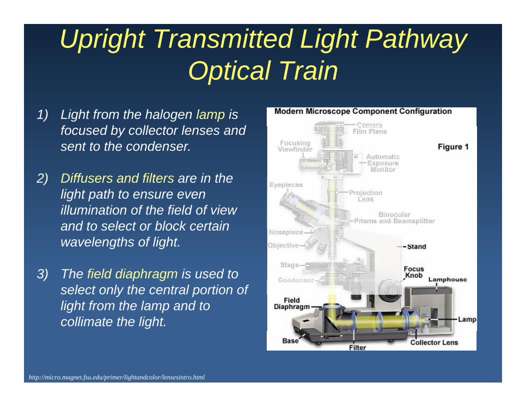
Upright Transmitted Light PathwayOptical TrainOptical Train
1) Light from the halogen lamp is f d b ll t l dfocused by collector lenses and sent to the condenser.
2) Diffusers and filters are in the2) Diffusers and filters are in the light path to ensure even illumination of the field of view and to select or block certainand to select or block certain wavelengths of light.
3) The field diaphragm is used to ) p gselect only the central portion of light from the lamp and to collimate the light.
http://micro.magnet.fsu.edu/primer/lightandcolor/lensesintro.html

Upright Transmitted Light PathwayOptical TrainOptical Train
4) The condenser is attached to th i b ththe microscope by the condenser carrier it provides focused even illumination across the field of view for aacross the field of view for a wide range of magnifications.
5) The specimen is placed on the5) The specimen is placed on the microscope stage.
6) The objective lenses are held in ) jplace by the nosepiece which can be turned putting different lenses in place.
http://micro.magnet.fsu.edu/primer/lightandcolor/lensesintro.html

Upright Transmitted Light PathwayOptical TrainOptical Train
7) The eyepieces (10x) magnify a i t l i f th l th tvirtual image of the sample that
generates a real image on the detector.
http://micro.magnet.fsu.edu/primer/lightandcolor/lensesintro.html

Upright Transmitted Light PathwayOptical TrainOptical Train
7) The eyepieces (10x) magnify a i t l i f th l th tvirtual image of the sample that
generates a real image on the detector.
8) The light can be redirected with a beam splitter to a detector, such as a CCD camerasuch as a CCD camera.
http://micro.magnet.fsu.edu/primer/lightandcolor/lensesintro.html

Inverted Transmitted Light Pathway
Illumination system above the specimen.
Objective lenses below the specimen.
Fixed location of stage and objectives move.
Good for living cells that need environmental control.
Modified by Aleks Spurmanis from http://zeiss-campus.magnet.fsu.edu/tutorials/axioobserver/index.html

Inverted Microscope Optical Train1) Light from the halogen lamp
is focused by collector lenses and sent to the condenser.
Modified by Aleks Spurmanis from http://zeiss-campus.magnet.fsu.edu/tutorials/axioobserver/index.html

Inverted Microscope Optical Train1) Light from the halogen lamp
is focused by collector lenses and sent to the condenser.
2) Diff d filt i2) Diffusers and filters are in the light path to ensure even illumination of the field of view and to select orof view and to select or block certain wavelengths of light.
3) The field diaphragm is used to select only the central portion of light from the
Modified by Aleks Spurmanis from http://zeiss-campus.magnet.fsu.edu/tutorials/axioobserver/index.html
p glamp and to collimate the light.
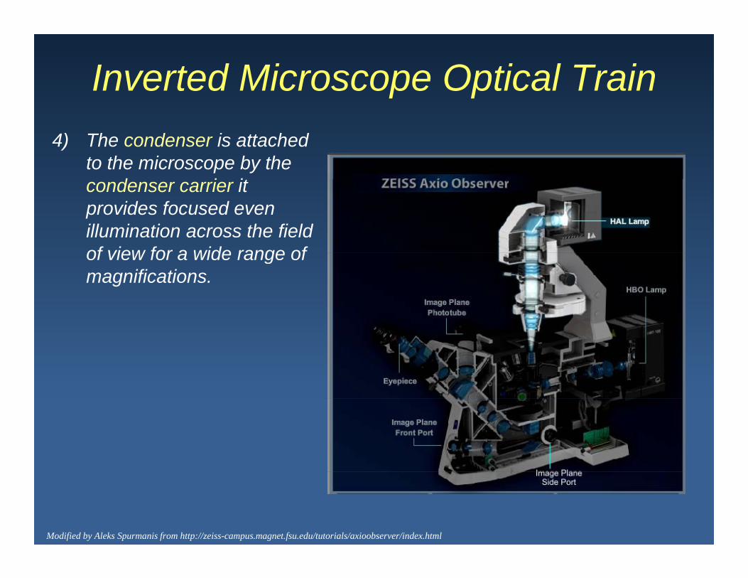
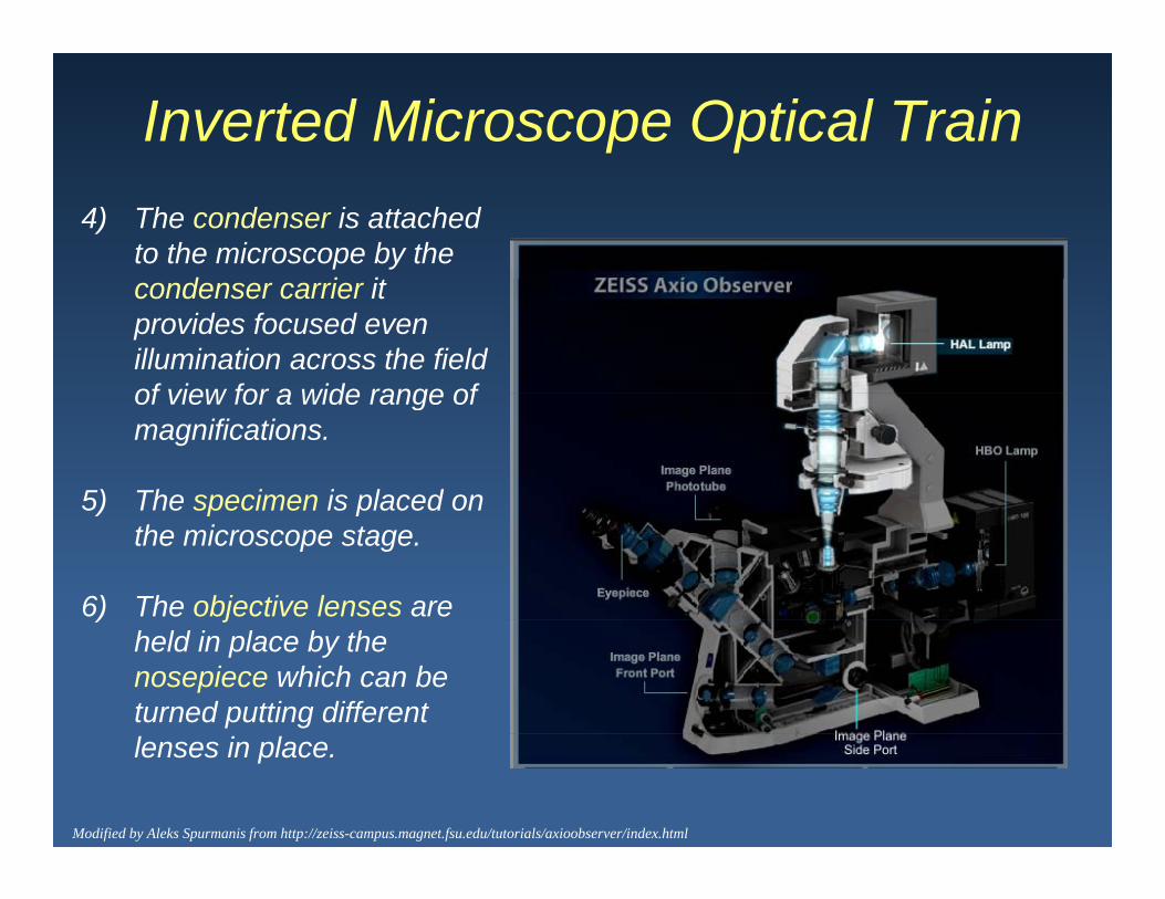
Inverted Microscope Optical Train4) The condenser is attached
to the microscope by the d i itcondenser carrier it
provides focused even illumination across the field of view for a wide range ofof view for a wide range of magnifications.
Modified by Aleks Spurmanis from http://zeiss-campus.magnet.fsu.edu/tutorials/axioobserver/index.html
Inverted Microscope Optical Train4) The condenser is attached
to the microscope by the d i itcondenser carrier it
provides focused even illumination across the field of view for a wide range ofof view for a wide range of magnifications.
5) The specimen is placed on5) The specimen is placed on the microscope stage.
6) The objective lenses are ) jheld in place by the nosepiece which can be turned putting different
Modified by Aleks Spurmanis from http://zeiss-campus.magnet.fsu.edu/tutorials/axioobserver/index.html
lenses in place.

Inverted Microscope Optical Train
7) The eyepieces (10x) if i t l i fmagnify a virtual image of
the sample that generates a real image on the detector.
Modified by Aleks Spurmanis from http://zeiss-campus.magnet.fsu.edu/tutorials/axioobserver/index.html

Inverted Microscope Optical Train
7) The eyepieces (10x) if i t l i fmagnify a virtual image of
the sample that generates a real image on the detector.
8) The light can be redirected with a beam splitter to a detector such as a CCDdetector, such as a CCD camera.
9) Camera front port.) p
10) Camera side port.
Modified by Aleks Spurmanis from http://zeiss-campus.magnet.fsu.edu/tutorials/axioobserver/index.html
Tutorial

Köhler Illumination
August Köhler (1866-1948): A German f h fi t d ib dprofessor who first described a new
way to illuminate microscope samples in 1893. He later went on to work for Carl Zeiss in Germany as a PhysicistCarl Zeiss in Germany as a Physicist for 45 years.
Köhl Ill i ti U d t tKöhler Illumination: Used to create even illumination over the specimen field of view without having an image of the light source in the field of viewthe light source in the field of view.

Conjugate Image PlanesConjugate Image Planes: A set of image planes that are optically linked and whose images are superimposed.
A collector lens focuses the light source at the back focal plane of the objective putting the front focal plane of the condenser and the filament i i j t l Th f th fil t i i limage in conjugate planes. Therefore, the filament image is no longer conjugate to the image plane, and is no longer visible.
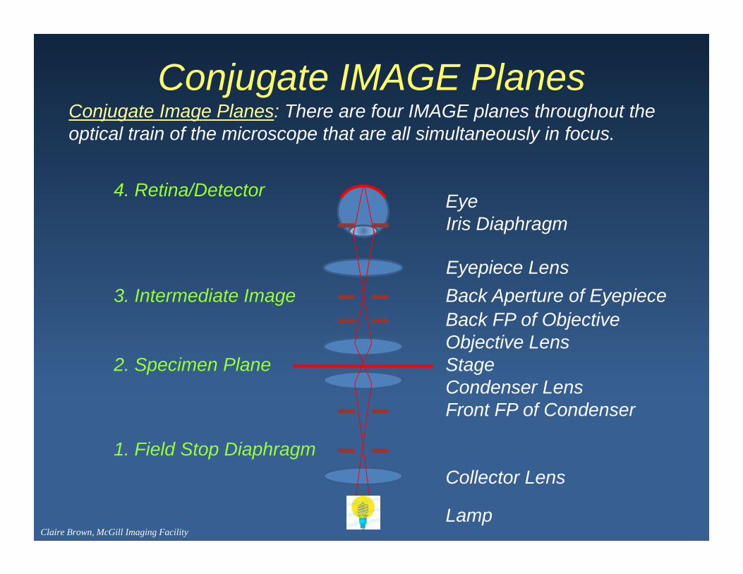
Conjugate IMAGE PlanesC j t I Pl Th f IMAGE l th h t thConjugate Image Planes: There are four IMAGE planes throughout the optical train of the microscope that are all simultaneously in focus.
4. Retina/Detector EyeIris Diaphragm
3. Intermediate ImageBack FP of ObjectiveBack Aperture of EyepieceEyepiece Lens
2. Specimen PlaneCondenser Lens
Objective LensStage
Back FP of Objective
1. Field Stop Diaphragm
Front FP of Condenser
Lamp
Collector Lens
Claire Brown, McGill Imaging Facility

Simple Biconvex Lens
Focal Planes (f and f’): planes that are one focal length away from either side of the lenseither side of the lens.
Modified by Aleks Spurmanis from http://www.olympusmicro.com/primer/anatomy/magnification.html

Conjugate IMAGE Planes
http://www.microscopyu.com/articles/formulas/formulasconjugate.html

Conjugate APERTURE PlanesConjugate Aperture Planes: There are four aperture planes throughout the optical train of the microscope that are all simultaneously in focus.
E4. Pupil of the Eye Eye
Back Aperture of Eyepiece
3. Back FP of ObjectiveObjective LensBack FP of Objective
Back Aperture of Eyepiece
2. Front FP of CondenserCondenser Lens
jStage
Front FP of Condenser
Collector Lens
1. Lamp Filament Lamp
Claire Brown, McGill Imaging Facility

Conjugate APERTURE Planes
http://www.microscopyu.com/articles/formulas/formulasconjugate.html

IMAGE and APERTUREPlanes are InterlacedPlanes are Interlaced
4. Retina/Detector
4. Pupil of the Eye
3. Intermediate Image3. Back FP of Objective
2. Specimen Plane
2. Front FP of Condenser
1. Field Stop Diaphragm
1. Lamp Filament
Claire Brown, McGill Imaging Facility

Image PlanesImage Planes
1. Field Diaphragmp g2. Specimen3. Intermediate Image4 Detection Plane4. Detection Plane
(Eye, CCD Camera)
http://www.microscopyu.com/articles/formulas/formulasconjugate.html

Aperture PlanesAperture planes
1. Lamp Filamentp2. Condenser Aperture3. Objective Back Focal Plane4 Pupil of the Eye4. Pupil of the Eye
http://www.microscopyu.com/articles/formulas/formulasconjugate.html

Image and Aperture Planes
Filament is unfocused where image is focusedwhere image is focused.
http://www.microscopyu.com/articles/formulas/formulasconjugate.html

Image and Aperture Planes
Image is unfocused where filament is focusedfilament is focused.
http://www.microscopyu.com/articles/formulas/formulasconjugate.html

Conjugate Planes
Three simultaneously focused conjugate image planes
http://www.microscopyu.com/articles/formulas/formulasconjugate.html
Tutorial

Köhler Illumination Alignment
1. Image forming light rays cross over at specimen and field diaphragm.
2. Optimal illumination enters the objective and is focused at the specimen.
Modified by Aleks Spurmanis from the Molecular Expressions Web Page
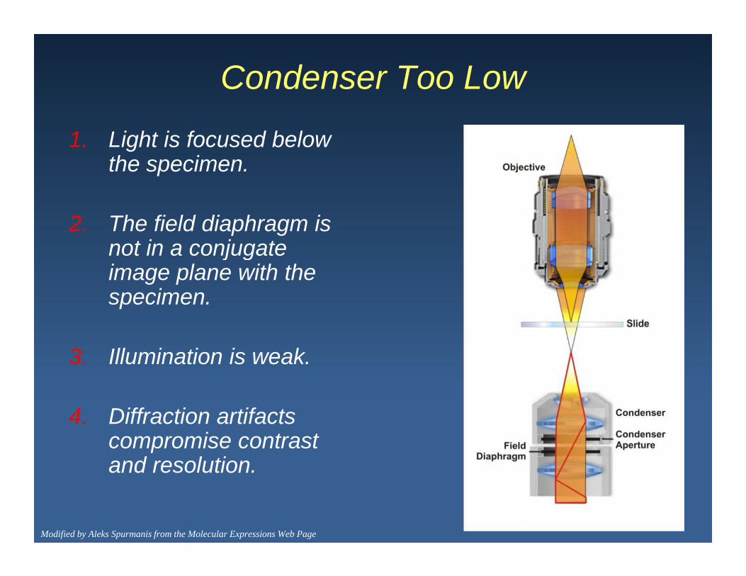
Condenser Too Low
1. Light is focused below the specimen.
2. The field diaphragm is not in a conjugatenot in a conjugate image plane with the specimen.
3. Illumination is weak.
4. Diffraction artifacts compromise contrast and resolutionand resolution.
Modified by Aleks Spurmanis from the Molecular Expressions Web Page

Condenser Too High
1. Light is focused above the specimenspecimen.
2. The field diaphragm is no p glonger in a conjugate image plane with the specimen.
3. Illumination is weak.
4. Diffraction artifacts compromise contrast and resolution.
Modified by Aleks Spurmanis from the Molecular Expressions Web Page

Köhler Illumination Alignment
1. Focus on the specimen.
McGill Imaging Facility

Köhler Illumination Alignment
1. Focus on the specimen.2. Close down the field diaphragm.
McGill Imaging Facility
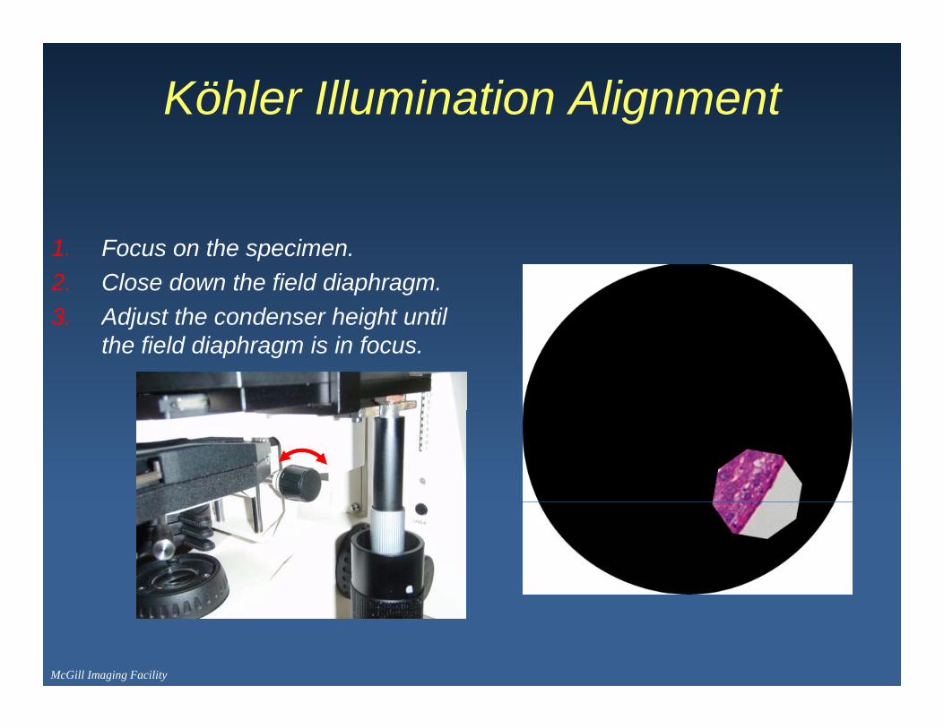
Köhler Illumination Alignment
1. Focus on the specimen.2. Close down the field diaphragm.3 Adjust the condenser height until3. Adjust the condenser height until
the field diaphragm is in focus.
McGill Imaging Facility

Köhler Illumination Alignment
1. Focus on the specimen.2. Close down the field diaphragm.3 Adjust the condenser height until3. Adjust the condenser height until
the field diaphragm is in focus.4. Center the condenser.
McGill Imaging Facility

Condenser Not Centered
1. Illumination is weak AND non-uniform.
2. Reduces contrast and resolution.resolution.
3. Can interfere with image analysisanalysis.
Modified by Aleks Spurmanis from the Molecular Expressions Web Page

Köhler Illumination Alignment
1. Focus on the specimen.2. Close down the field diaphragm.3 Adjust the condenser height until3. Adjust the condenser height until
the field diaphragm is in focus.4. Center the condenser.5 Fine tune the centering5. Fine tune the centering.
McGill Imaging Facility

Köhler Illumination Alignment
Best contrast when condenser is set to ~80% of the size of the objective back japerture.
Modified by Aleks Spurmanis from the Molecular Expressions Web Page
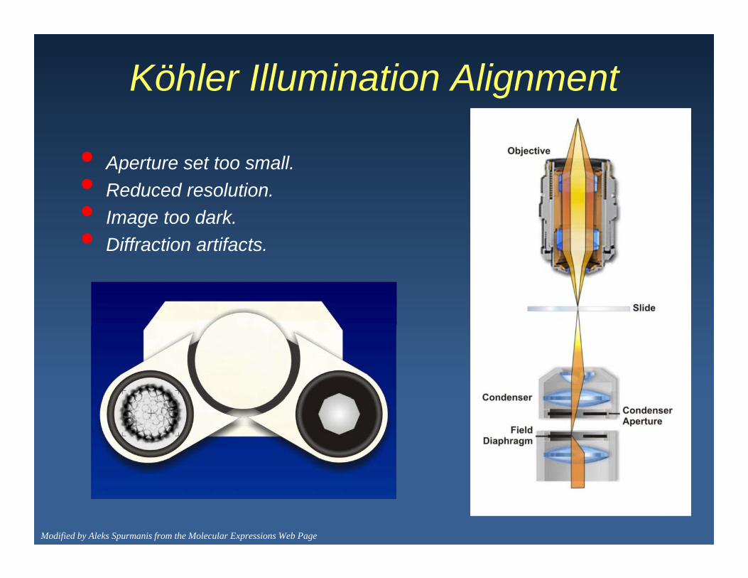
Köhler Illumination Alignment
• Aperture set too small.•• Reduced resolution.• Image too dark.• Diffraction artifacts.
Modified by Aleks Spurmanis from the Molecular Expressions Web Page
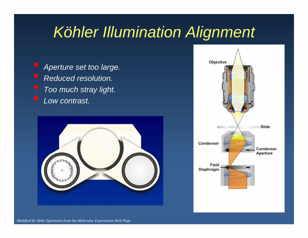
Köhler Illumination Alignment
• Aperture set too large.•• Reduced resolution.• Too much stray light.• Low contrast.
Modified by Aleks Spurmanis from the Molecular Expressions Web Page

Microscope Alignment
Köhler Aligned Microscope Mis-Aligned Microscope
Claire Brown, McGill Imaging Facility

Microscope Alignment
Köhler Aligned Microscope Mis-Aligned Microscope
Claire Brown, McGill Imaging Facility

The Lenses, Transmitted Light Optical Train and Köhler Alignment Talk wasTrain and Köhler Alignment Talk was
Clearly Presented
1. Strongly Disagreeg y g2. Disagree3 Neutral3. Neutral4. Agree5. Strongly Agree

The Lenses, Transmitted Light Optical Train and Köhler Alignment Talk wasTrain and Köhler Alignment Talk was
Relevant to My Work
1. Strongly Disagree2. Disagree3. Neutral4. Agree5 Strongly Agree5. Strongly Agree

The Lenses, Transmitted Light Optical T i d K hl Ali T lkTrain and Köhler Alignment Talk was:
1. Too Short2. Too Long3. A Good Lengthg