system vrac basic certikin · 5 "important: this instruction manual contains basic information...
TRANSCRIPT

BASIC AUTOMATIC MULTIPORT VALVEVANNE MULTIVOIES AUTOMATIQUE BASICVÁLVULA SELECTORA AUTOMÁTICA BASICVALVOLA SELETTRICE AUTOMATICA BASICAUTOMATISCHES MEHRWEGE VENTIL BASICVÁLVULA SELECTORA AUTOMÁTICA BASIC
INSTALLATION AND MAINTENANCE MANUALMANUEL D’INSTALLATION ET D’ENTRETIENMANUAL DE INSTALACIÓN Y MANTENIMIENTOMANUALE DI INSTALLAZIONE E MANUTENZIONEINSTALLATIONS-UND BEDIENUNGSANLEITUNGENMANUAL DE INSTALAÇÃO E MANUTENÇÃO


5
"Important: This instruction manual contains basic information with respect to safety measures which should be adopted during installation and putting into service. For this reason, it is essential that both the installer and user carefully read these instructions before carrying out any installation or putting into service operations."
In order to obtain optimum performance from the automatic valve, it is recommended that the instructions given below are strictly followed.
General safety prescriptions:
These symbols indicate the possibility of danger as the consequence of not respecting the corresponding prescriptions.
DANGER. Risk of electrocution. The lack of warning of this prescription involves a risk of electrocution.DANGER. The lack of warning of this prescription involves a risk of personal injury or material damages.WARNING. The lack of warning of this prescription involves a risk of damage to the automatic valve or the installation.
GENERAL SAFETY REGULATIONSGENERAL.
The valve described in this manual has been specially designed to provide correct water circulation in the swimming pool during the various operational phases.It has been designed to work with clean water at temperatures not exceeding 35ºC.The installation must be carried out in accordance with the specific instructions for each particular implementation.Current in-force regulations for the prevention of accidents must be observed.Any modification to the valve’s electronic module requires the prior authorisation from the manufacturer. Original spare parts and accessories authorised by the manufacturer will guarantee greater safety. The manufacturer of this automatic valve is exempt from all responsibility for any damage caused by non-authorised spare parts or accessories.During operation, the valve’s electric and electronic parts have electric power connected to them.Any work to the automatic valve and any equipment connected to it, must only be carried out when the start-up devices have been disconnected.The user must ensure that installation and maintenance work is carried out by adequately qualified and authorised personnel, and these have previously carefully read the installation and service instructions.Automatic valve operational safety is only guaranteed by full compliance and respect of the installation and service instructions.The maximum voltage values must never be exceeded under any circumstances.In the case of incorrect operation or a fault, please contact the closest manufacturer’s representative or technical assistance service.
ENGLISH
6
ADVICE DURING INSTALLATION AND ASSEMBLY OPERATIONS.During the connection operations of the electrical wiring to the valve modules, great attention must be given to polarity, and it must be verified that pieces of wiring are not left inside after closing.Make all connections by following the instructions in this manual.It should be verified that the electrical wiring connections to the valves electronic card are firmly made.The seal on the module’s box should be checked for correct positioning to prevent the entry of water, it should also be checked that the compression gland is also correctly located Particular attention should be paid, so that, under no circumstances, is it possible for water to enter the electronic module. In the case where the intended use is not that for which the valve was designed, adaptation and supplementary technical regulations may be necessary.
ADVICE FOR WHEN PUTTING INTO SERVICE.
Before putting the automatic valve into service, it is necessary to verify the calibration of the electrical protection devices in the operations cabinet and that they are correctly positioned and fixed in place.
NOTE: It is recommended that the bathing facilities are not used while the filtration equipment is in operation.
ADVICE DURING INSTALLATION AND MAINTENANCE WORK.
National installation regulations must be taken into account when assembling and installing the automatic valve.Extra care must be taken so that it is not possible, under any circumstances, for water to enter the automatic valve electronic circuit.All contact, including accidental, must be avoided at all times with the moving parts in the automatic valve during operation and/or before complete shutdown.Before carrying out any maintenance or any other electrical or electronic work, it must be ensured that switch-on devices are locked.It is recommended that the following steps be taken before performing any maintenance on the automatic valve.
1.- Remove electrical power to the valve. 2.- Lock the switch-on devices. 3.- Verify that there is no electrical power being applied to the circuits, including auxiliary and supplementary services.
This list must be considered indicative and not binding with respect to safety, there may be other specific safety standards in particular regulations.
IMPORTANT: due to the complexity of the situations covered, the instructions for installation, use and maintenance contained in this manual, do not make any attempt to cover all possible service and maintenance cases. If additional instructions are necessary or specific problems arise, please do not hesitate in contacting the distributor or the valve manufacturer directly. Our automatic valves may only be installed in swimming or other pools which fully comply with the HD 384.7.702 standard. When any doubt exists a specialist should be consulted.
Please check the packing contents.
ENGLISH

7
CONTENTS
1. Valve characterisctics 1.1 Verification of valve type 1.2 Flow diagram for the various valve operating positions 1.3 Specifications 1.4 Control module 2. Installation 2.1 Electrical connection 2.2 Example of connecting a single phase 230 V electrical cabinet 2.3 Fuse 2.4 Pressostat adjustment 2.5 Drainage safety
3. Maintenance and guarantees 3.1 Hydraulic installation maintenance 3.2 Specific valve maintenance 3.3 Guarantees
4. Operating and programming 4.1 Control cover 4.2 Timed backwashed switch 4.3 Programming 4.4 Drainage (on “filtration” position and while timer program stopped) 4.5 Drainage (forced while timer program running) 4.6 Test 4.7 Backwash press button 5. Instructions for removing the module installed on the valve 5.1 Valve disassembly procedure 5.2 How to disassemble the valve module 5.3 Instructions for installing the module on the valve 5.4 Temporary conversion of the system to manual operation 5.5 How to change the valve from manual to automatic operation
6. Identifying errors
7. Annexes 7.2 Appendix 1: Valve assembly and dismantling
ENGLISH

8
1. VALVE CHARACTERISTICS
1.1 VERIFICATION OF VALVE TYPE.Multiport valve, 1½” Model BASIC - 115-230VAC (50-60 Hz); Model 2” BASIC - 115-230VAC (50-60 Hz). Both the model and code are indicated on a label, together with the valve operating specifications and the label itself is located on the rear section of the electronic module cover which is installed on the valve.Valve hydraulic and electrical operation are verified before it leaves the factory.It is recommended that before carrying out the installation, a visual inspection be performed in case any knocks were received which could have damaged the valve.The valve will be replaced in any justified complaint.
1.2 FLOW DIAGRAM FOR THE VARIOUS VALVE OPERATING POSITIONS.
The valve should be installed in the filter following the instructions provided in the included leaflet.The valve may be positioned on the side or top of the filter, in whichever position is most comfortable for subsequent use.Installation under load, the maximum water column that can be supported by the pump is six metres (19.68 ft).The hydraulic connections for correct operation are made by following the markings on the valve itself.PUMP indicates the connection coming from the pump.TOP indicates the upper input to the filter.BOTTOM indicates the lower return from the filter to the valve.RETURN indicates the return from the valve to the swimming pool.WASTE indicates the connection to the drains.
Introduction to the filtration process operation:The pump sucks water from the swimming pool via the skimmer, bottom cleaner or drain, it is taken to the multiport valve (PUMP connection) and from here to the filter (TOP). It passes through the filter bed and returns to the valve once again via the BOTTOM connection and is taken back to the swimming pool by means of the RETURN connection.The valve includes a pressure switch which is factory set to an operating pressure of 1.5kg/cm2 (21.3 psi). If this requires further adjustment, it should be set to the pressure of the installed pump, adjustment range: 0.3 to 2 kg/cm2 (4.2-28.4 psi). According to requirements, it can be installed with an adjustment of between 1 and 6 kg/cm2 (14.22-85.3 psi).If the pressure exceeds the pre-established limit, the valve will automatically change over to the Backwash position.This change can also be automatically time controlled, after 7 days of the valve being connected to the mains supply.
ENGLISH

9
Wash process:The valve automatically reverses the filtration cycle and commences the sand wash process, this requires that the valve is set so that the water coming from the PUMP connection passes through the valve and is taken to the filter by the BOTTOM connection, the sand is stirred and the water, together with any accumulated dirt exits the valve TOP connection which communicates with the WASTE connection and is taken to the drains. This process is carried out in accordance with the pre-established timing.
Back-wash process:The valve is positioned to compress the filter bed and not to send water containing sand to the swimming pool, this is achieved by water coming from the PUMP connection entering the filter by the TOP connection, it then compresses the sand and the water enters the valve via the BOTTOM connection which then sends it to the WASTE connection. This process is carried out in function of the pre-established time and once it has elapsed, the valve commences the filtration process again.
1.3 VALVE SPECIFICATIONS
Sizes 1½” and 2”, side and top mountingValve body manufactured in ABSInternal distributor manufactured in PPOConnection via threaded female, BSP or NPT, BOTTOM connection for gluingMaximum operating pressure 3.5 barsTest pressure 5.2 bars
ENGLISH

10
ENGLISH
1.4 CONTROL MODULE.
This is the part of the valve which consists of a geared motor and an electronic card with limit switches for the various valve operational positions.An electronic circuit, which emits commands commands so that the pre-established program is executed.Mechanical components which carry out the various valve movements.The entire assembly is mounted inside a transparent casing which is closed by four screws.The module features a cover with push buttons and LEDs to indicate its various functions.The electrical input and output connections are protected by compression glands which provide perfect protection against external agents which could damage the assembly.The power supply is 115-230 AC Volts.
2. INSTALLATION.
2.1 ELECTRICAL CONNECTION.
Follow the following instructions in order to prepare the control box and its connection to the electronic module:
- Power Supply: when connecting to the electronic module, it is advisable to take the current from the control box, connect it to the “out” terminal of the differential (if used) or else connect the L, N and T terminals from the magneto thermal breaker to the corresponding L, N and T terminals of the electronic module. Without polarity.
- Contactor's coil control: cut the contactor coil A1 and connect to the terminal "+" (J10) on the module. Connect terminal "-" to the contactor coil A1. Don't worry about polarity.
Please see electric diagram for a clearer explanation of these connections.All connecting leads between module and control box should have a section of 0.7 mm2. It is advisable to use a three lead cable in order to ensure a watertight fit with the gland.

11
ENGLISH
ELECTRICAL CABINET AFTER CONNETING
INCORRECT CONNECTION

12
ENGLISH
2.2 EXAMPLE OF CONNECTING A SINGLE PHASE 230 V ELECTRICAL CABINET
Before proceeding with the installation of the materials, users must ensure that the assembly and maintenance work is carried out by qualified and authorised workers who have read and unders-tood the installation and service instructions. The following diagram shows the external connections required to connect a System VRAC multi-port valve to an ASTRALPOOL 25717 cabinet.Disconnect the A1 end of the cable leading from connection 2 of the 3-position switch and add a terminal block for the valve connection.
A1 / A2 are the terminals used to connect the filtration pump's contactor coil. Terminal J10 of the multiport valve must always be connected to connection A1 of the contactor coil.It is important to ensure that nothing is connected in parallel with the solenoid valve of the pump contactor and that the total power consumption does not exceed 0.4 A.In cases where another component has to be connected which needs be activated at the same time as the pump, we recommend the use of an auxiliary contact of the pump contactor.

13
2.3 FUSE
The valve's electronics board incorporates a safety fuse to prevent any damage being caused to the J10 connection. As stated in the previous point, incorrect connections or other connected components which increase power consumption at the connection between the solenoid valve of the pump contactor and the valve may result in operational faults.A fuse therefore prevents the consumption through this conductor exceeding 0.4 A, thus preventing such faults. In the event that the fuse fails, check the electrical installation to ensure that it matches the electrical diagram before replacing the fuse with a new one of the same specifications (5x20).
0.4 A fast acting fuse.
2.4 PRESSOSTAT ADJUSTMENT.
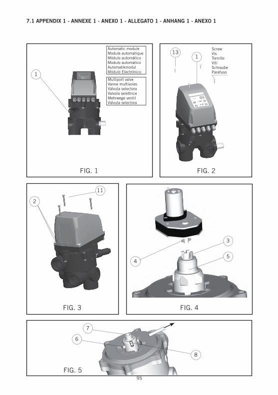
Use the filter or valve manometer as a reference guide when reading the pressure gauge. Proceed as follows:1º Turn the pressostat screw (1) (APPENDIX 1 – fig. 1) until it is flush with the black piece (it is
not necessary to tighten it all the way). 2º With the pump running, close the return valve going to the pool until the desired pressure level
is displayed on the manometer.3º Gently slacken the pressostat screw (1) (APPENDIX 2 – fig. 1) until the LED on the electronic
board comes on (1) (APPENDIX 3). This LED can be seen throught the transparent cover at the bottom on the right. After 10 seconds, the pump will stop.
4º IMPORTANT. Open the pool return valve.5º The pool’s return tube has to be equipped with a ball valve to ensure a correct adjustment.
2.5 DRAINAGE SAFETY.
The valve comes ready to be installed in an electrovalve in the drainage circuit. Its use is recommended in order to avoid water loss in case the electric flow is insufficient and the valve ends up in a position that could lead to the pool emptying. The electrovalve used should have as low a pump pressure orifice as possible (0.4 - 0.5 bars). The voltage of the solenoid should be 24 Volts AC. (See APPENDIX 1 - Fig. 9)
ENGLISH

14
3.3 GUARANTEES.
The valves leave the factory in a fully tested condition, which enables us to guarantee operation. The guarantee will be effective provided that the installation and maintenance has been correctly carried out and this requires that the actual installation operation be performed by a person with the necessary qualifications for this type of work.
3. MAINTENANCE AND GUARANTEES.
3.1 HYDRAULIC INSTALLATION MAINTENANCE
Regular maintenance needs to be carried out on all components of the pool's hydraulic circuit in order to ensure optimum operation of the installation and thereby prevent damage to the valve or any other components. The maintenance operations that may have a direct impact on the operation of the multiport valve are listed below:- Be sure to empty and wash the skimmer baskets on a regular basis to keep them clear of leaves and any other waste. Baskets should be replaced if they are damaged.- Be sure to empty the basket of the pump pre-filter, clearing away leaves and any other waste. Replace the basket in the event of damage.- Regulate the suction and return valves by adjusting the valve's pressure switch before setting the filter wash pressure. This operation should be repeated whenever a component is changed or added to the installation or whenever the regulation setting of the valves is changed.
3.2 SPECIFIC VALVE MAINTENANCE
The internal elements of the valve require regular maintenance in accordance with the followingspecifications:- Perform all operations with the pump off and with the input and output valves to the filter and
the multiport valve closed. - Remove the actuator as described in point 6.2 of the manual. - Remove the remaining 3 screws holding the valve cover in place. - Remove the cover to allow access to the internal distributor. - Lift the distributor and clean the area around the distributor seal, clearing away any residue that
may hinder rotation. - At least once a year, grease the O-rings on the distributor shaft to facilitate the movement of the
distributor. The grease used to lubricate the O-rings should be TURMSILON GL320 NLGI 1-2 (LUBCON). The manufacturer supplies the specified grease together with the valve. The guarantee will be valid provided that all installation and maintenance operations are carried out correctly.
Grease
ENGLISH

15
ENGLISH
Filtration:
1º Programme the filtration time via the timer to be found in the control box.2º Programme wash time using the push button control on the cover of the electronic module,
pressing (+) or (-) to select the desired time shown in minutes on the LED display (when the valve performs this function the LED display will flash).
3º Programme rinse time using the push button control on the cover of the electronic module, pressing (+) or (-) to select the desired time shown in minutes on the LED display (when the valve performs this function the LED display will flash). If any button is pushed during the wash and rinse cycles, in order to change the time programmed, the time entered will remain programmed for the next time the appliance is used.
WARNING: when the valve is on “filtration” position and out of the hour programming, the pump can be started by using the switch (position “forced” “1” – see APPENDIX 1).
If the filter pressure rises while the valve is working in this position, the pressure switch will activate and start the backwashing and rinsing processes.
4. OPERATING ANG PROGRAMMING
4.1 CONTROL COVER
The valve’s module cover features a panel with push buttons and LEDs to indicate its various functionsTEST – Indicates potential problems that might affect the valve (flashing)WASTE-VACIADO – Indicates drainage function(-) Reduces programmed time(+) Increases programmed time(0.5’ 1’ 2’ 3’ 4’) Indicates programmed wash time (in minutes)(20” 40”) Indicates length of programmed rinse cycle (in seconds)In the event of an interruption to the power supply, the programmed times for wash and rinse cycles will be erased, settings reverting to the default setting of 0.5’ and 20” until the appliance is re-programmed.A conventional control box (if possible, an AstralPool model) is always necessary in order to programme filtration for your automatic valve set.The basic components necessary in the control box are: Differential (advisable) Magneto thermal breaker, pump contactor, Position switch (on “II”, high “I”) and timer programmer.
4.2 TIMED BACKWASH SWITCH
The bottom right hand area of the electronics board (2) (APPENDIX 2 Item 2) contains a microswitch used to connect ("ON" position) and disconnect ("OFF" position) the 7-day cleaning function.The 7-day timer resets when:- The 7-day cleaning function has completed- A pressure clean has completed- Power is connected or reconnected after a power outage. All cleaning will be pressure cleaning while the 7-day microswitch is set to the "OFF" position.
4.3 PROGRAMMING.

16
ENGLISH
4.4 DRAINAGE (on “filtration” position and while timer program stopped).
Operation to be performed manually. Follow these steps:
1º Press “WASTE / VACIADO” on the electronic module
for 3 seconds until the LED comes
on, the valve will now be in the Drainage position.
2º Turn the switch in the control box to the “I” position, thus activating the pump and starting the drainage process.
These operations are to be carried out when the valve is in the “filtration” position. If the wash or rinse cycles are running, please wait until they have finished.
Appliance users should watch for when this operation finishes. Once the appliance has stopped, proceed as follows:
1º Turn switch to “II” position in the control box in order to stop pump
2º Press “WASTE / VACIADO” on the electronic module
for 3 seconds until the LED goes off, the valve will now be in the filtration position.
4.5 DRAINAGE (forced while timer program running)
1º Press 3 seconds until the led lights up. The electronic module will stop the pump and the valve will turn to “WASTE” position. The pump will start up again.
2º To stop the process press again. The module will stop the pump and the valve will turn to “FILTRATION” position.
4.6 TEST.
This is used in order to:1º Know when the appliance is connected to the mains (LED lit).2º Flashing LED indicates possible operational problem:
- Two flashes: Stop microswitch not found, the microswitch may be broken. - Four flashes: excessive motor consumption due to bell braking, possibly caused by incorrect
filter operation which is allowing sand to pass through the system. - Six flashes: Failure of the bell elevation microswitch.
4.7 BACKWASH PRESS BUTTON
On this valve there is a push button (see Photo) which enables the backwash routine to be started (wash + rinse) without having to use the pressure switch or the return valve. The valve must be correctly connected to the electrical cabinet and the program timer activated.In order to start the operation, press the button and maintain the pressure for at least 7 seconds. Once the routine is finished, the valve returns to the filter position. The backwash and rinse times are in accordance with the indications on the valve.

17
ENGLISH
5. DISASSEMBLY PROCEDURE
5.1 Valve disassembly procedure: The automatic valve consists of two sections, the hydraulic part which includes a conventional valve and an automatic module.The filter valve is disassembled in the same manner as a manual valve.
5.2 How to disassemble the electronic module: (illustrations in APPENDIX 1) BEFORE ANY OPERATION IS CARRIED OUT ON THE VALVE, IT MUST DISCONNECTED FROM THE POWER SUPPLY.Disassembly: First remove the four screws which hold the cover (1) in place. (Fig. 2).Disconnect all input wires to the module (AAPPENDIX 1 - Fig. 8). WARNING: All mains power supply connections must be removed first. Refit the cover 1 (Fig. 2)Remove the three screws (11) which hold the module in place on the valve (Fig. 3).Carefully remove the module in an upwards direction.Protect inside suitable packaging to prevent any damage and send it to the manufacturer.From this point there are two possibilities:1. Replacement of the module.2. Temporarily convert the system to manual valve operation.
5.3 Instructions for installing the module on the valve. The manufacturer will ship the valve-module assembly to the technical service or installer ready for installation. It should be installed as follows:
1. Install the valve assembly by positioning the module so that marking 2 (APPENDIX 1 - Fig. 3) coincides with the mark on the valve cover, carefully lower the module until it is correctly in place with respect to the screw 3 (APPENDIX 1 - Fig. 4). In a situation where it does not fit, the screw may be rotated until it couples with the motor pin (4) (APPENDIX 1 - Fig.4). Care must be taken not to lower it too brusquely since this could damage the module’s microswitches.
2. Install the three screws (11) (APPENDIX 1 - Fig. 3 ).3. Remove the cover 1 (APPENDIX 1 - Fig. 2) by removing the four screws (13) in order to access
the connection strip.4. Connection (MAKE SURE THERE IS NO MAINS VOLTAGE). Connect the cables as indicated
in the attached diagram. IMPORTANT! Use the gland seals that come installed in the module.5. Replace the cover 1 (APPENDIX 1 - Fig. 2) and replace it with the screws (13).6. Connect the power input to the control board. The valve will be in the Filtration position, standing
by for when the programmed time is entered.
Backwash press button

18
ENGLISH
5.4 Temporary conversion of the system to manual operation. The module should be dismounted as described in Section 5.2.Once the supply system is out, unplug the wires in the control box (L-N) that supply the electronic module.Disconnect the wires from terminal (J10) on the electronic module and connect thme to each other with a bridge between these two terminals.Remove screw (3) (APPENDIX 1 - Fig. 4), and pull the pawl (5) upwards, then (see APPENDIX 1 - Fig. 5) remove the pin (6) in the direction of the arrow sale, remove part (7), leaving the valve in position for installing the handle.To install the handle, position the handle* (14) (APPENDIX 1 - Fig. 6) such that the triangle on the bell shaft always coincides with the handle positioner (9). Once it is installed, the pin* (10) can be inserted .In the event that there is an electrovalve in the drainage system, turn the lever (APPENDIX 1 – Fig. 9 - detail 1) to position manual.The 3 position switch, On “II”, Hi “I” should be in the “I” position.
* Supplied as spare parts.
5.5 How to change the valve from manual to automatic operation. Remove the pin (10) (APPENDIX 1 - Fig. 6), remove the handle (14) and install the part (7) (APPENDIX 1 - Fig. 5). This is accomplished by orienting the mark (A) such that it coincides with the triangle (APPENDIX 1 - Fig. 6). Once fitted in place, the pin (6) (APPENDIX 1 - Fig. 5) should be inserted, which should be centred along its length. Then install the part (5) (APPENDIX 1 - Fig. 4). Slot the inside notch (15) into the mark (16). See assembly illustration in APPENDIX 1, fig.7. Which should be well-positioned (it only has one mounting direction). Insert the screw (3) and screw in. It should not be fully tightened since it has to be loosened in order to orient it with the pin (4) on the motor assembly. At this point, it is now possible to install the module assembly as described in the valve module installation process.In the event that there is an electrovalve in the drainage system, turn the lever (APPENDIX 1 – Fig. 9 - detail 1) to position nº2 (automatic). Control box: The 3 position switch, On “II”, Hi “I” should be in the “II” position.
6. IDENTIFYING ERRORS
The situation might arise that owing to the a problem in installation (air working in depression) the time needed to prime the pump is greater than that programmed for the wash and rinse cycles, something that would cause the valve to start this operational mode without the filter working correctly.

19
PROBLEM CAUSE SOLUTION
The valve does not start up and the LED is either not lit or all lights are flashing
Incorrect electrical connection Check the power connection and the control connection of the contactor's solenoid valve.
The actuator does not work and the red light is flashing twice
Failure of the position micro Contact technical assitance
The actuator does not work and the red light flashes 4 times
The valve distributor is blocked
Disconnect the power supply and take off the actuator. Take off the valve lid, clean the dis-tributor and aply grease shaft and o-rings with TURMSILON GL320 grease.
The actuator does not work and the red light flashes 6 times
Problem with the distributor ascend micro
Check the connection from the micro to the J2. If the problem persists, gert in contact with Technical Assistance
The buttons on the keypad do not work
The connecting cable is dis-connected
Check that it is correctly connected
The valve keeps on doing washings with the pressure switch LED lit up
The pressure is not correctly graduated
Consult the manual to correctly adjust the pressure switch
The return ball valve is closed or nearly closed
Open the ball valve
There is a faulty connection in the pressure switch circuit
Check the pressure switch connection cable
The pump does not stop when it is changing position
The terminal block J10 and the control cabinet are con-nected incorrectly
Check that the connection matches the wiring diagram
The valve does not work and the fuse has blown
There is an incorrect electrical connection producing an excessive level of power consumption at terminal J10 of the valve
Measure the consumption level at the J10 connection and check the electrical installation
The waste water electro-valve does not oper (in the case that one has been installed)
The polarity of the cables has not been respected
Check the cable connections: red to positive and black to negative
Error in the electronic board Use a tester to check the tension in the electro-valve terminal: if it is less than 15 Vdc, contact Technical Assistance
Error in the electro-valve If the tension is correct, the problem has to be in the electro-valve
ENGLISH
95
7.1 APPENDIX 1 - ANNEXE 1 - ANEXO 1 - ALLEGATO 1 - ANHANG 1 - ANEXO 1
1Multiport valveVanne multivoiesVálvula selectoraValvola selettriceMehrwege ventilVálvula selectora
FIG. 1 FIG. 2
ScrewVisTornilloVitiSchraubeParafuso
113
FIG. 3
11
2
FIG. 4
45
3
FIG. 5
8
7
6
Automatic moduleModule automatiqueMódulo automáticoModulo automaticoAutomatikmodulMódulo Electrónico

96
FIG. 6
Triangle markRepère triangulaireMarca del trianguloRiferimento del triangoloDreiecksmarkierungMarca do triângulo
10
914
FIG. 7
Notch (15)Repère (15)Resalte (15)Rilievo (15)Vorsprung (15)Ressalto (15)
Mark (16)Rainure (16)Ranura (16)Scanalatura (16)Nut (16)Ranhura (16)
FIG. 8
ww
w.n
eevi
aPDF
.com

97
FIG. 9
7.1 APPENDIX 1 - ANNEXE 1 - ANEXO 1 - ALLEGATO 1 - ANHANG 1 - ANEXO 1

98
Solenoid valve - ÉlectrovanneElectroválvula - ElettrovalvolaElektroventil - Electroválvula
red cable: solenoid connection (+)câble rouge: branchement du solénoïde (+)cable rojo: conexión solenoide (+)cavo rosso: collegamento del solenoide (+)rotes Kabel: Verbindung mit Spule (+)cabo vermelho: ligação do solenóide (+)
black cable: solenoid connection (-)câble noir: branchement du solénoïde (-)cable negro: conexión solenoide (-)cavo nero: collegamento del solenoide (-)schwarzes Kabel: Verbindung mit Spule (-)cabo preto: ligação do solenóide (-)
Connection of Control Panel/Cover to Actuator Connexion clavier/couvercle - actionneurConexión teclado/tapa - actuador Colleqamento tastiera/coperchio - attuatoreVerbindung Tastatur/Deckel - StellantriebConexão teclado/tampa - actuador
The cover is supplied with the pin connector discon-nected as a safety measure in order to allow an easier connection between the control box and the automatic module.
Le couvercle est fourni avec le connecteur à pins déconnecté: il s’agit d’une mesure de sécurité pour faciliter le branchement électrique entre l’armoire et le module électronique.
La tapa se suministra con el conector de pins des-conectado como medida de seguridad para facilitar el conexionado eléctrico entre armario y módulo electrónico.
Il coperchio viene fornito con i connettori pin scollega-ti per rendere più facile il collegamento tra il quadro elettrico ed il modulo elettronico.
Als Sicherheitsmaßnahme, um die elektrischen Schal-tanschlüsse zwischen Schrank und elektronischem Modul zu erleichtern, wird der Deckel mit nicht an-geschlossenem Pin-Steckverbinder geliefert.
A tampa é fornecida com o conector de pins desli-gado como medida de segurança para facilitar a instalação eléctrica entre quadro da bomba e módulo electrónico.
Once the required electrical connections have been finished, install the connector ensuring every pin is connected.
Après avoir procédé aux branchements élec-triques nécessaires, monter le connecteur en veillant à ce que tous les pins soient bien connectés.
Una vez se hayan realizado las conexiones eléctricas oportunas, montar el conector procurando que no quede ningún pin sin conexión.
Una volta effettuate le connessioni elettriche opportune, montare il connettore assicuran-dosi che tutti i pin siano collegati.
Nach Herstellung der entsprechenden elek-trischen Schaltungen ist der Steckverbinder zu montieren und dabei zu beachten, dass alle Pins einwandfrei angeschlossen sind.
Uma vez estando as conexões eléctricas correctamente realizadas, montar o conec-tor procurando não deixar nenhum pin sem conexão.
Correctly installed connection. In case the valve needs to be dismantled, it is important to disconnect the pins with the cover slightly raised in order to avoid breaking the ribbon cable.
Connecteur monté correctement. Si le démontage de la vanne s’avère nécessaire, il est important de décon-necter les pins avec le couvercle légèrement relevé en évitant ainsi de rompre la bande.
Conector correctamente montado. En el caso de que fuera necesario desmontar la válvula, es importante desconectar los pins con la tapa ligeramente levantada, evitando de esta forma que se pueda romper la cinta.
Connettore installato correttamente. Nel caso in cui fosse necessario smontare la valvola, è importante scollegare i pin con il coperchio leggermente alzato per evitare di rompere il cavo.
Steckverbinder ordnungsgemäß eingebaut. Sollte die Demontage der Automatikarmatur erforderlich sein, so sind unbedingt die Verbindungen der Pins bei leicht angehobenem Deckel zu trennen, um einen Bandbruch zu vermeiden.
Conector correctamente montado. No caso de ser ne-cessário desmontar a válvula, é importante desligar os pins com a tampa ligeiramente levantada, evitando des-ta forma que se rompa a cinta.
1
7.2 APPENDIX 1 - ANNEXE 1 - ANEXO 1 - ALLEGATO 1 - ANHANG 1 - ANEXO 1
2