system testing with object-oriented programs...
TRANSCRIPT
System Testing with
Object-Oriented Programs
Dissertation
Dafydd Vaughan327039
January 14, 2007
Abstract
Today’s software systems have become increasingly complex with morerisks associated with failure. This has meant that a greater importancehas been placed on testing to ensure the software works correctly andmatches the specification. This document looks at software testing andnew technologies and techniques that can be used to both improve theefficiency and rigour of testing software.

CS339 Testing Dissertation - Dafydd Vaughan 327039 2
Contents
Outline 4
1 Introduction 5
1.1 Why Test Software? . . . . . . . . . . . . . . . . . . . . . . . . . 5
1.2 Document Aims . . . . . . . . . . . . . . . . . . . . . . . . . . . . 6
2 Background 7
2.1 Levels of Software Testing . . . . . . . . . . . . . . . . . . . . . . 7
2.1.1 Requirements Testing . . . . . . . . . . . . . . . . . . . . 8
2.1.2 Design Testing . . . . . . . . . . . . . . . . . . . . . . . . 8
2.1.3 Module Testing . . . . . . . . . . . . . . . . . . . . . . . . 9
2.1.4 Unit Testing . . . . . . . . . . . . . . . . . . . . . . . . . 9
2.1.5 Integration Testing . . . . . . . . . . . . . . . . . . . . . . 9
2.1.6 System Testing . . . . . . . . . . . . . . . . . . . . . . . . 9
2.1.7 Acceptance Testing . . . . . . . . . . . . . . . . . . . . . . 10
2.2 Object Oriented Programming . . . . . . . . . . . . . . . . . . . 10
2.3 Unified Modelling Language (UML) . . . . . . . . . . . . . . . . 10
2.3.1 The History of UML . . . . . . . . . . . . . . . . . . . . . 11
2.3.2 UML Diagrams . . . . . . . . . . . . . . . . . . . . . . . . 11
3 System Testing 14
4 Automating Testing 15
4.1 Example . . . . . . . . . . . . . . . . . . . . . . . . . . . . . . . . 15
4.2 Requirements Analysis & Low Level Design . . . . . . . . . . . . 16
4.3 Activity Diagrams . . . . . . . . . . . . . . . . . . . . . . . . . . 16
4.4 The Use Cases . . . . . . . . . . . . . . . . . . . . . . . . . . . . 17
CS339 Testing Dissertation - Dafydd Vaughan 327039 3
4.5 Expanding the Use Cases . . . . . . . . . . . . . . . . . . . . . . 18
4.6 The Final Steps . . . . . . . . . . . . . . . . . . . . . . . . . . . . 20
5 Conclusion 21
Glossary 22
References 24

CS339 Testing Dissertation - Dafydd Vaughan 327039 4
Outline
In recent years, software testing has become an increasingly important part ofthe development of new systems. Many high profile failures of new systems -some even fatal - have created a bad image of the software development industry.This image, together with the growing use of computers in safety-critical andbusiness-critical areas have forced developers to place a greater emphasis ontesting software to make sure it works correctly and successfully matches therequirements of their customers. New testing techniques and practices includinginternational standards for specifying how systems should work - such as UnifiedModelling Language (UML) - have been established.
Despite these huge improvements, the time taken to complete the testing ofsoftware to a satisfactory level is increasing. This is, in part, due to the increaseddetail of the testing taking place, but is also caused by the growing complexityof today’s software. Further research is being conducted into automating someof this testing process to enable quicker software testing to take place.
The first part of this document (section 1) looks at some of the problems facedby the software testing industry and why we test new software. Section 2 looksat some of the background topics such as the different levels of software test-ing, object oriented programming and the Unified Modelling Language (UML).Section 3 looks in more detail about testing completed systems to make surethey satisfy their specifications, and Section 4 looks at one of the ways in whichUML can be used to automate the process.

CS339 Testing Dissertation - Dafydd Vaughan 327039 5
1 Introduction
1.1 Why Test Software?
Until recently, comprehensive software testing has been considered as an unim-portant part of software development[5]. Businesses viewed the process of fullytesting software an unnecessary expenditure in both time and money. Develop-ers saw the process as boring and repetitive. These views meant that softwareunderwent only as much testing as was necessary to launch the product. Thetesting that was performed usually happened at the end of the developmentcycle. It therefore, only consisted of checking the software worked, and not thatit matched the requirements of the project.
This attitude towards testing meant that software development gained a neg-ative image. In addition to this, a large number of systems produced did notcompletely match their original specification and a large amount of money andtime was spent making changes to these systems to correct these problems.These delays undermined the credibility of the system even when it was finallydelivered.
One example of the problems caused by a lack of testing was seen in 1999 whenthe UK Passport Agency introduced a new computer system in two of its sixoffices. This system aimed to replace its older systems, making the handling ofpassport applications easier. It was planned to be rolled out to all six officesbefore the busy season in mid 1999[11]. However, after being implemented intwo of the offices - Liverpool and Newport - the system failed, resulting in ahuge backlog of applications. The situation was made worse by customers whostarted to loose confidence in the system. The public began making applicationsearlier than usual, increasing the backlog. By the end of June 1999, applicationswere up by 29 per cent.
The cost of dealing with this high profile failure amounted to around £12.6million, not including approximately £9 million in lost business borne by thedevelopers of the system.
Another good example of the potential seriousness of this attitude are the in-cidents from the Therac-25 radiation therapy machine. In these cases, therewere at least 6 deaths and other serious injuries caused by massive radiationoverdoses[9]. These events have been attributed to a fault in the control softwareof the device that had not been picked up during testing. Accidents like thisin safety-critical systems have potentially lethal consequences. Comprehensivetesting the software is essential to prevent these problems.
With such high profile failures the need to develop comprehensive testing sys-tems has grown momentum. The introduction of computers into more and moresafety-critical systems such as the aviation and medical industries has made test-
CS339 Testing Dissertation - Dafydd Vaughan 327039 6
ing essential. The numerous high profile failures due to incorrect specificationshas led to businesses questioning how new systems are developed. They havebegun to realise that the cost of software testing outweighs the potential costsof making changes after production as well as the potential loss of money andlife should safety-critical or business-critical systems fail.
Recently, other problems have arisen with software testing. Computer softwareis becoming bigger and much more complex. This has meant that it has becomemore complicated to test and the time taken to complete each level of testing hasincreased. However, research and new technologies such as modelling languagescould potentially help solve this problem. Testing research is now looking atways of automating some of this process to speed up the time taken to testsoftware and create more efficient tests.
These changed attitudes have meant that testing has become much more im-portant and is a growing industry. In some cases, testing is considered moreimportant than the code itself. So, how can the industry develop cost effectivecomprehensive testing with increasingly complex code? Could the testing beaccomplished through programs themselves, thereby automating some of theprocess?
1.2 Document Aims
The following pages of this dissertation will look at the levels of testing thattake place during the development cycle. We will consider how object orientedsoftware changes the way system testing is performed. We will also look at howthis object oriented software makes use of modelling languages such as UML toquickly develop test cases and reduce the time taken to complete this level oftesting.
CS339 Testing Dissertation - Dafydd Vaughan 327039 7
2 Background
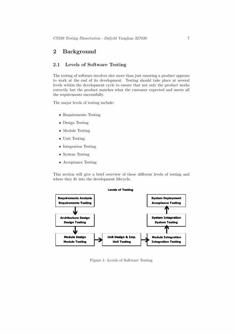
2.1 Levels of Software Testing
The testing of software involves alot more than just ensuring a product appearsto work at the end of its development. Testing should take place at severallevels within the development cycle to ensure that not only the product workscorrectly but the product matches what the customer expected and meets allthe requirements successfully.
The major levels of testing include:
• Requirements Testing
• Design Testing
• Module Testing
• Unit Testing
• Integration Testing
• System Testing
• Acceptance Testing
This section will give a brief overview of these different levels of testing andwhere they fit into the development lifecycle.
Figure 1: Levels of Software Testing

CS339 Testing Dissertation - Dafydd Vaughan 327039 8
When software is produced, it idealy progresses through seven levels of devel-opment - known as the development lifecycle (shown in figure 1). At the startof the project, the developers work along side the customer to develop a ‘Re-quirements Specification’. This specification outlines exactly what the programshould be able to achieve, how it is supposed to achieve it, and even what hard-ware it should be run on. The second stage of development involves designingthe system architecture and the ‘modules’ of code which will need to be pro-duced. Once this design is completed, stages three and four involve creatingthese modules and fitting them together to produce ‘units’ of code.
The fifth stage of development will take these units and merge them (alongwith any 3rd party code) to produce a complete system. This stage is calledintegration and is the last stage that involves working with the code of thesoftware. The second to last stage of development will see the software installedon the system that will be used by the customer, and finally the completedsoftware will be deployed so it can be used.
Each stage of development has a level of testing associated with it to ensurethe stage has been completed successfully, these are discussed in the followingsections.
2.1.1 Requirements Testing
Requirements Testing is the first level of software testing and should take placewhile producing the requirements specification from which the product will beproduced[13]. One of the biggest problems with developing software is that it isvery often designed based on wrong, vague or missing lists of requrements. Thisis one of the major reasons why new computer systems fail to meet expectations.
Requirements testing is intended to help reduce the possibility of software beingdeveloped that does not meet the expectation of the customer. This level oftesting also has the added benefit that it will reduce the large costs of bothtime and money involved in changing the final software should it not meet allthe requirements.
2.1.2 Design Testing
Design Testing is performed to ensure that the architecture of the system isdesigned correctly to meet all the requirements specified in the previous level[14].If this design is correct, the developers can then begin to produce tbe code foreach module of the system to perform the desired functions. This level of testingis very important as an error introduced at this level could be very expensiveand time consuming to resolve later in the development cycle.

CS339 Testing Dissertation - Dafydd Vaughan 327039 9
2.1.3 Module Testing
Once the modules designed above have been constructed by the project develop-ers, they will need to be tested to ensure that they work correctly[1]. This stageof testing is called Module Testing. These modules are tested using the testcases and data developed during the previous stage of the project. This levelaims to reduce the number of incorrect modules passed on to the unit develop-ment stage - thus reducing the overall number of errors which could potentiallyoccur later in development.
2.1.4 Unit Testing
Unit Testing is intended to check that groups of modules work together cor-rectly. This level of testing occurs before all the units are integrated into thefinal system and just concentrates on ensuring that small groups of modules(units) work together. The purpose of this level of testing is again to reduce thepossibility of errors being passed onto the next level of software develoment.
2.1.5 Integration Testing
Integration Testing is performed once all the modules and units have been com-bined together to produce the final complete system[4]. This level of testing isperformed to ensure all the units of the system work together as expected andinterface issues are minimised. This level of testing is extremely important asunits are usually produced independently and this is the first occasion in whichthey are joined together. It is also an important level of testing when using 3rdparty components which have not been tested in previous levels due to copyrightissues. These components will be used for the first time when integrated intothe full system.
Integration testing is the final stage of testing in which the inner workings ofthe program (the code) is examined. All future levels are considered Black boxand look only at the results produced.
2.1.6 System Testing
System Testing is concerned with ensuring the final system matches the specifi-cation layed out in the requirements at the beginning of the project. This is thefinal stage of testing before the customer sees the completed program. Furtherdetails of system testing can be found in section 3.

CS339 Testing Dissertation - Dafydd Vaughan 327039 10
2.1.7 Acceptance Testing
Acceptance Testing is the final level of testing that will take place in the softwaredevelopment cycle. This stage will take place after the software is released to thecustomer and is intended to ensure that the software satisfies the requirementsset by the customer[10]. If the software passes these tests, it will be accepted bythe customer as final and complete. Unlike other levels of testing, acceptancetesting is performed by the customer - not the developer - and ensures thatthe software they are receiving is fit for purpose and satisfies their needs. Allthe previous levels of testing are intended to increase the likelyhood that thesoftware produced will pass this level of testing. Should the software fail here,it could be very expensive to make the required changes to bring it inline withthe specification and will also undermine confidence in the system which couldeven lead to delays from customers refusing to use it.
2.2 Object Oriented Programming
Object oriented programming is a way of developing software from groups of‘objects’[12]. The use of objects instead of classical procedures makes objectoriented programming more logical as its use of objects usually relate to groupsof functions. For example, in a library system you might have the objects ‘cus-tomer’, ‘book’ and ‘loan’. The ‘customer’ object would contain all the variablesrelated to a customer - such as name, address, contact number and number ofbooks on loan - as well as methods (actions) such as ‘send overdue notice’ whichsends the customer an overdue notice.
One of the biggest advantages of object oriented programming is code reuse. Ob-jects can easily be reused in other applications, cutting down the developementtime. This however also presents a potential problem for testing. Regularly inlarge systems, 3rd party components and objects will be used to provide someof the functionality. In many cases, it is not possible for developers to test thesemodules as the code is not available to them. Instead, they must rely on the3rd party adequately testing the component. Integration testing becomes veryimportant in this situation as it is the first time that the developers can testthe module and its interfaces.
Object oriented software also affects other aspects of testing such as the compo-sition of the modules and units. In object oriented software, modules are morelikely to be methods and units are likely to be objects or groups of objects. Inclassic programming this distinction is less obvious.
2.3 Unified Modelling Language (UML)
CS339 Testing Dissertation - Dafydd Vaughan 327039 11
UML is the international standard for designing, specifying and modelling com-puter systems. In this section we will outline what UML is and the history ofthis language.
2.3.1 The History of UML
Prior to 1994, there was no standard method or notation with which to modela computer system. Many books had been written about the design and anal-ysis of software but no standard had emerged. Of these different methodolo-gies, three stand out. Grady Booch a developer from Rational Software hada methodology based on Ada; Jim Rumbaugh, who led a team of researchersat General Electric, developed a method called Object Modeling Technique(OMT). Ivar Jacobson also developed a method based on his experience withtelephone switches for Ericsson[3]. All of the methods of the time were con-sidered similar but with very different notation which caused confusion in theindustry. However talk of standardization was avoided by each of the developers.
This changed in 1994 when work began to unify these three methods to createUML. In 1995, Booch and Rumbaugh merged their two modelling techniquesto create the ‘Unified Method version 0.8’. Later, Jacobson joined the pair andUnified Method was merged with his object oriented technique to create ‘Uni-fied Modelling Language 0.9’[8]. In early 1997 UML was proposed to the ObjectManagement Group (OMG) as its standard for modelling information technol-ogy systems. The Object Management Group is a not-for-profit organisationthat develops and maintains specifications for enabling applications to work to-gether in the computer industry. The OMG accepted UML as their standard inNovember 1997.
Several revisions to the standard have taken place since it was adopted withthe latest version - UML 2.0 - being released in October 2004. UML has nowbeen accepted as an international standard by the International Organizationfor Standardization (ISO) - number ISO/IEC 19501:2005.
2.3.2 UML Diagrams
Unlike other languages, UML is a modelling language that consists of graphicaldiagrams to specify the system. The latest UML standard - UML 2.0 - consists of13 different diagrams split into 2 categories - structural diagrams and behavioraldiagrams. In this section we will briefly describe each diagram and how theyare used to specify a system.
The structural diagrams below are used to show the structure of the system anddetail how objects relate to each other. This category consists of six diagrams- Class, Component, Composite structure, Deployment, Package and Object
CS339 Testing Dissertation - Dafydd Vaughan 327039 12
diagrams.
Class Diagrams
These diagrams show the composition of the classes and interfaces (and theirrelationships) that make up the system being modelled. Very detailed classdiagrams can be used to quickly generate code.
Component Diagrams
These diagrams show how the full system is split into several independent sub-systems. These diagrams group several classes together and provide an interfacefor accessing them. As a result, they provide a Black box view of the imple-mentation.
Composite Structure Diagrams
These diagrams provide a link between class diagrams and composite diagramsbut do not show the same level of detail. They show how elements are combinedto show complex relationships. This type of diagram is new to UML 2.0.
Deployment Diagrams
These diagrams show how the system is configured at deployment and show howthe components of this software are linked to the hardware that will execute it.
Package Diagrams
These are an extension of the class diagrams and show how classes and interfacesare grouped together.
Object Diagrams
These diagrams are very similar to class diagrams but instead show how theinstances of a class are related at a point in time.
The behavioral diagrams below are used to show how elements within the systembehave and the operations they can perform. This category consists of sevendiagrams - Activity, Communication, Interaction overview, Sequence, State Ma-chine, Timing and Use case diagrams.
Activity Diagrams
These diagrams show the flow of the sytem from one activity to another. Theyare similar to classic flow charts but provide more detail. These diagrams arealso used to help automate testing and will be discussed in more detail later.
Communication Diagrams
CS339 Testing Dissertation - Dafydd Vaughan 327039 13
These diagrams are similar to interaction overview diagrams and are used toshow the elements involved in system interactions. Unlike sequence diagrams,they do not show detailed sequencing or timing.
Interaction Overview Diagrams
These diagrams are similar to activity diagrams but show the objects that areinvolved in performing each activity.
Sequence Diagrams
These diagrams are the most common behaviour diagrams used in UML andare based on Interaction diagrams. These show the type and sequence of themessages passed between system objects during execution.
State Machine Diagrams
State diagrams show the different states in which part of the system can resideduring execution and the transitions between them. The part of the diagramshown can be a single class, a group of classes or the entire system.
Timing Diagrams
These diagrams are similar to sequence and interaction diagrams but concen-trate on the timing specifications of the message - such as how long the systemhas to respond to a message once it is received.
Use Case Diagrams
These diagrams show the functional requirements of the system. They providea view of the system that focusses on use needs. Use Case diagrams are animportant part of object oriented system testing and wil be used in later sectionsto show how to create test cases.

CS339 Testing Dissertation - Dafydd Vaughan 327039 14
3 System Testing
System testing is one of the levels of testing that comes just before the customerof the product gets to see the final version. This level of testing is concernedwith ensuring that the program matches the specification that was drawn up atthe beginning of the project[6] One of the most important points to make aboutsystem testing is that unlike integration testing, it is not concerned with howthe system works. Instead, it is more concerned with the results produced. Forthis reason, system testing is considered to be ”Black box”. This means it justlooks at what happens on the outside but cannot look on the inside.
(a) White box (b) Black box
Figure 2: White Box and Black Box Testing
Another point to make about system testing is that it should take place in aset up that accurately reflects (as much as possible) the system in which theproduct will be deployed. This way, errors caused by the customers setup canbe found and fixed prior to release.
On the surface, it would appear that system tests for object oriented systemswould be no different to system tests for non-object oriented systems. Whilethis essentially is the case, since system testing is black box and not concernedwith how the program works, the process of actually generating the test casesis different. Specifications for object oriented software can be very differentfrom non-object oriented software. For example, object-oriented systems canbe modelled in UML (as seen in 2.3) and use ‘Use Case’ and ‘Class’ diagrams.These diagrams are then used to produce the test cases. This process is discussedin the next section.

CS339 Testing Dissertation - Dafydd Vaughan 327039 15
4 Automating Testing
The automation of testing is currently a very active research area. Computersystems have become extremely complex and the need to subject software torigorous testing has become essential. However, these factors have also dramat-ically increased the time taken to perform comprehensive tests to a satisfactorylevel - the more complex the system, the more tests are needed to be certainthe system works correctly.
In business terms, the more time spent testing the software, the higher the devel-opment costs and the later the product will be made available to the cutomers.It has become essential to reduce the time taken to test the software withoutreducing the effectiveness of the tests. Test automation is a possible answer tothis.
Software developed in object oriented languages can be modelled in UML andthis specification can then be used to automatically generate the tests to berun, test cases and create test engines. It is hoped that this will significantlycut down the time required to test new software.
In this section we will look at the use of UML Use Case diagrams, Activitydiagrams and Interaction diagrams to help automate part of the process ofsystem testing.
4.1 Example
In the following sections we will refer back to a standard example for consistency.The example we have chosen to use is that of a simple currency converter[7](see figure 3). This currency converter can convert US Dolars to Brazilian Real,Canadian Dollars, European Union Euros and Japanese Yen.
The currency converter has the following requirements:
• The user can input an amount into an input box
• The user can select the currency to convert to
• When selecting a currency, a flag is displayed for that currency
• Clicking a ‘compute’ button outputs the equivalent amount into an outputbox
• There is no limit on the number of conversions that can be performed
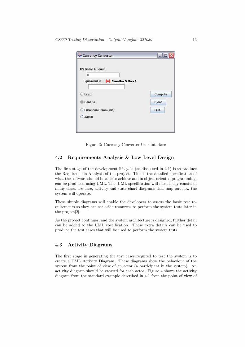
CS339 Testing Dissertation - Dafydd Vaughan 327039 16
Figure 3: Currency Converter User Interface
4.2 Requirements Analysis & Low Level Design
The first stage of the development lifecycle (as discussed in 2.1) is to producethe Requirements Analysis of the project. This is the detailed specification ofwhat the software should be able to achieve and in object oriented programming,can be produced using UML. This UML specification will most likely consist ofmany class, use case, activity and state chart diagrams that map out how thesystem will operate.
These simple diagrams will enable the developers to assess the basic test re-quirements so they can set aside resources to perform the system tests later inthe project[2].
As the project continues, and the system architecture is designed, further detailcan be added to the UML specification. These extra details can be used toproduce the test cases that will be used to perform the system tests.
4.3 Activity Diagrams
The first stage in generating the test cases required to test the system is tocreate a UML Activity Diagram. These diagrams show the behaviour of thesystem from the point of view of an actor (a participant in the system). Anactivity diagram should be created for each actor. Figure 4 shows the activitydiagram from the standard example described in 4.1 from the point of view of
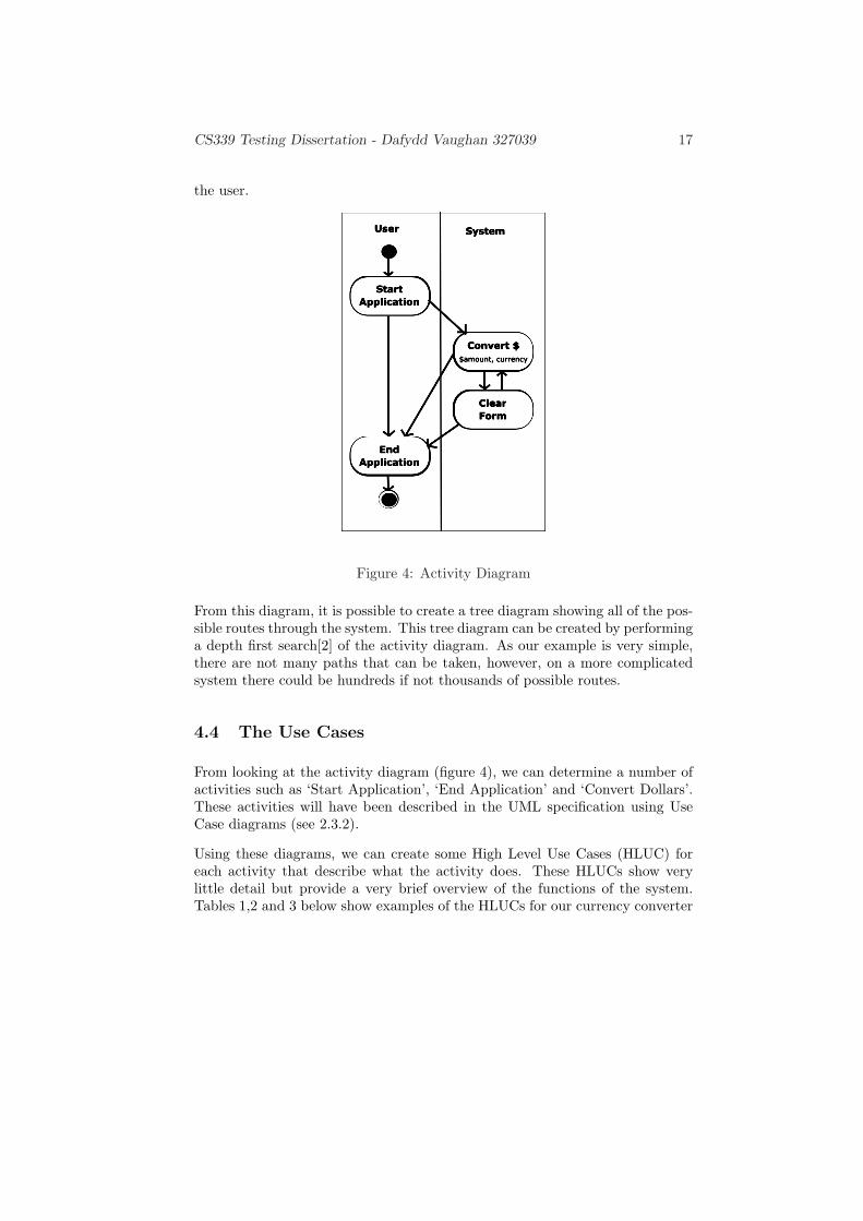
CS339 Testing Dissertation - Dafydd Vaughan 327039 17
the user.
Figure 4: Activity Diagram
From this diagram, it is possible to create a tree diagram showing all of the pos-sible routes through the system. This tree diagram can be created by performinga depth first search[2] of the activity diagram. As our example is very simple,there are not many paths that can be taken, however, on a more complicatedsystem there could be hundreds if not thousands of possible routes.
4.4 The Use Cases
From looking at the activity diagram (figure 4), we can determine a number ofactivities such as ‘Start Application’, ‘End Application’ and ‘Convert Dollars’.These activities will have been described in the UML specification using UseCase diagrams (see 2.3.2).
Using these diagrams, we can create some High Level Use Cases (HLUC) foreach activity that describe what the activity does. These HLUCs show verylittle detail but provide a very brief overview of the functions of the system.Tables 1,2 and 3 below show examples of the HLUCs for our currency converter
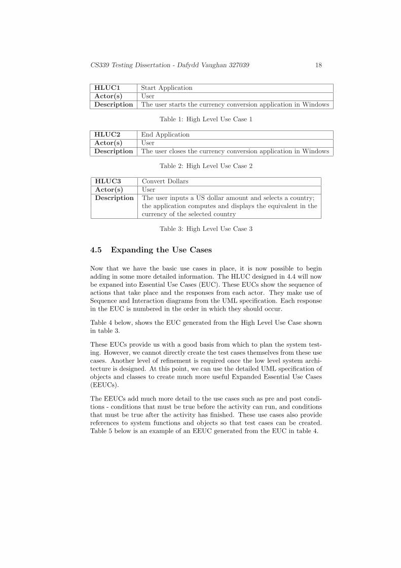
CS339 Testing Dissertation - Dafydd Vaughan 327039 18
HLUC1 Start ApplicationActor(s) UserDescription The user starts the currency conversion application in Windows
Table 1: High Level Use Case 1
HLUC2 End ApplicationActor(s) UserDescription The user closes the currency conversion application in Windows
Table 2: High Level Use Case 2
HLUC3 Convert DollarsActor(s) UserDescription The user inputs a US dollar amount and selects a country;
the application computes and displays the equivalent in thecurrency of the selected country
Table 3: High Level Use Case 3
4.5 Expanding the Use Cases
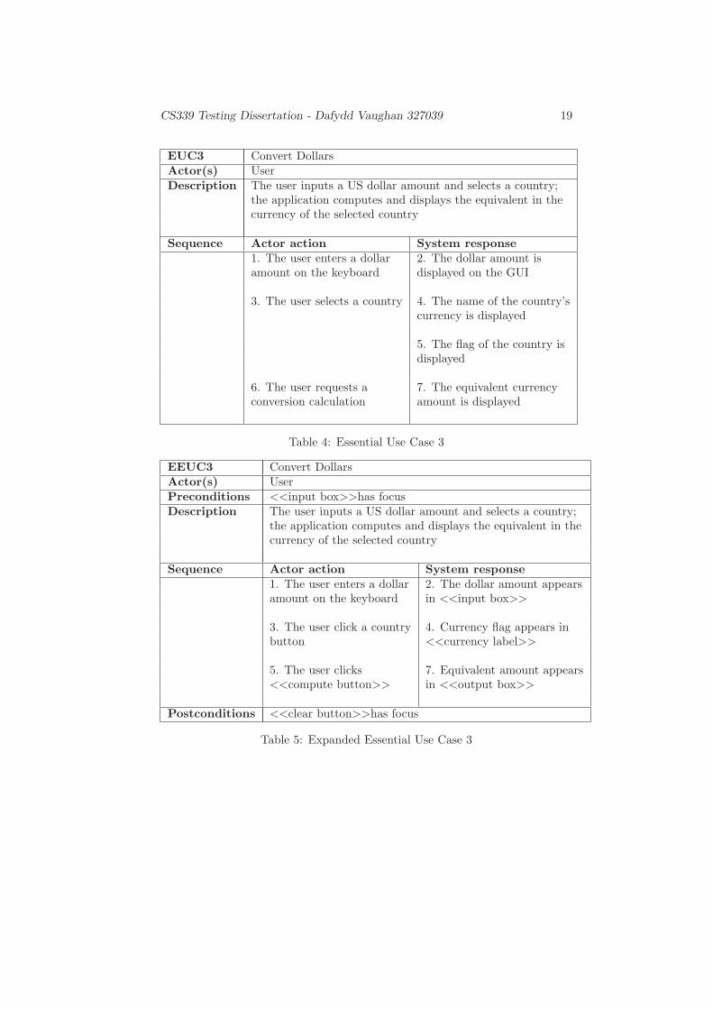
Now that we have the basic use cases in place, it is now possible to beginadding in some more detailed information. The HLUC designed in 4.4 will nowbe expaned into Essential Use Cases (EUC). These EUCs show the sequence ofactions that take place and the responses from each actor. They make use ofSequence and Interaction diagrams from the UML specification. Each responsein the EUC is numbered in the order in which they should occur.
Table 4 below, shows the EUC generated from the High Level Use Case shownin table 3.
These EUCs provide us with a good basis from which to plan the system test-ing. However, we cannot directly create the test cases themselves from these usecases. Another level of refinement is required once the low level system archi-tecture is designed. At this point, we can use the detailed UML specification ofobjects and classes to create much more useful Expanded Essential Use Cases(EEUCs).
The EEUCs add much more detail to the use cases such as pre and post condi-tions - conditions that must be true before the activity can run, and conditionsthat must be true after the activity has finished. These use cases also providereferences to system functions and objects so that test cases can be created.Table 5 below is an example of an EEUC generated from the EUC in table 4.
CS339 Testing Dissertation - Dafydd Vaughan 327039 19
EUC3 Convert DollarsActor(s) UserDescription The user inputs a US dollar amount and selects a country;
the application computes and displays the equivalent in thecurrency of the selected country
Sequence Actor action System response1. The user enters a dollar 2. The dollar amount isamount on the keyboard displayed on the GUI
3. The user selects a country 4. The name of the country’scurrency is displayed
5. The flag of the country isdisplayed
6. The user requests a 7. The equivalent currencyconversion calculation amount is displayed
Table 4: Essential Use Case 3
EEUC3 Convert DollarsActor(s) UserPreconditions <<input box>>has focusDescription The user inputs a US dollar amount and selects a country;
the application computes and displays the equivalent in thecurrency of the selected country
Sequence Actor action System response1. The user enters a dollar 2. The dollar amount appearsamount on the keyboard in <<input box>>
3. The user click a country 4. Currency flag appears inbutton <<currency label>>
5. The user clicks 7. Equivalent amount appears<<compute button>> in <<output box>>
Postconditions <<clear button>>has focus
Table 5: Expanded Essential Use Case 3

CS339 Testing Dissertation - Dafydd Vaughan 327039 20
4.6 The Final Steps
Now that we have created the Expanded Essential Use Cases, the next step is tocreate the test cases - or Real Use Cases (RUCs). To create RUCs, we edit theEEUCs to contain ‘real’ values - e.g. “Enter 10 into <<textbox>>” instead of“Enter value into <<textbox>>”. Table 6 shows an example of an RUC forthe EEUC in table 4.
The biggest problem with generating real use cases is determining the valuesto use. The values used must cover as many problem inputs as possible toensure that the system handles them correctly without causing an error. It isnot possible to test the system with every available value as this would takean infinite amount of time. This means that the chosen values must also be asefficient as possible. A further question is - can this process be automated? Theanswer to this is possibly - this is a topic of continued research and the industryhopes that by automating this step, software will become much more reliableand cost effective.
RUC3 Convert DollarsActor(s) UserPreconditions <<input box>>has focusDescription The user inputs $10 and selects the European Community;
the application computes and displays the equivalent¤7.50 in the <<output box>>
Sequence Actor action System response1. The user enters 10 on the 2. 10 appears in <<inputkeyboard box>>
3. The user clicks European 4. EU flag appears inCommunity button <<currency label>>
5. The user clicks 7. 7.50 appears in <<output<<compute button>> box>>
Postconditions <<clear button>>has focus
Table 6: Real Use Case 3
CS339 Testing Dissertation - Dafydd Vaughan 327039 21
5 Conclusion
Poor system testing has led to the production of faulty products and softwarewhich does not perform the task it was intended to do. This, together with theincreased complexity of today’s software and the risks associated with it failinghas led to more rigourous and cost effective software testing being undertaken.Many different testing processes have been created to improve the quality ofour software. The introduction of UML as an industry standard helps softwaredevelopers better specify their systems to ensure they match the requirementsof their customers.
However, despite all of these improvements, the process of making software morereliable is not complete. Further changes and improvements to the processesused are being made all the time. UML has recently been the focus of a majorupgrade with work already starting on the next enhancement. Further researchis also being undertaken, including work on the automation of testing to speedup the process. All of this should mean that software developed in the futureshould be much more reliable and much better tested than that produced today.
Despite more and more complicated software, the industry looks forward to lessstrenuous testing. This will come through the adoption of improved testingtools and techniques. The industry will no doubt see better testing, but withless effort.

Glossary 22
Glossary
Acceptance Testing This level of testing is performed by the cus-tomer to confirm that the software satisfies allof its requirements., 6, 8
Black box Black box testing means testing the systemwhile not looking at the the code inside (justlooking at the results produced)., 8, 11, 13
Design Testing This level of testing aims to ensure that the sys-tem architecture has been designed to satisfy allthe requirements of the specification., 6, 7
EEUC Expanded Essential Use Cases expand EUCs toinclude pre/post conditions and references tosystem functions / objects., 17
EUC Essential Use Cases extend HLUCs to includeactor actions and system responses., 16
HLUC High Level Use Cases provide a brief overviewof system functions., 16
Integration Testing This level of testing aims to ensure that the com-plete system works as expected without produc-ing errors., 6, 8
Module Testing This level of testing aims to ensure that theconstructed modules work correctly before be-ing implemented into bigger units., 6, 7
Requirements Testing This level of testing aims to ensure the require-ments which are used to develop the softwareare accurate., 6, 7
RUC Real Use Cases replace values in EEUCs withreal world values. These can be considered astest cases., 17
System Testing This level of testing aims to ensure that thecompleted system matches the specification de-signed at the beginning of the project., 6, 8
Glossary 23
UML Unified Modelling Language is an internationalstandard for graphically modelling systems ininformation technology., 3, 5, 9, 10, 13, 14, 16,20
Unit Testing This level of testing aims to ensure that com-plete units of modules work correctly beforethey are integrated into the full system., 6, 8
White box White box testing means testing the systemwhile looking at how the code works., 13

Glossary 24
References
[1] W. Richards Adrion, Martha A. Branstad, and John C. Cherniavsky. Vali-dation, verification, and testing of computer software. ACM Comput. Surv.,14(2):159–192, 1982.
[2] Lionel C. Briand and Yvan Labiche. A uml-based approach to systemtesting. In UML ’01: Proceedings of the 4th International Conference onThe Unified Modeling Language, Modeling Languages, Concepts, and Tools,pages 194–208, London, UK, 2001. Springer-Verlag.
[3] N. Pitman D. Pilone. UML 2.0 in a Nutshell. O’Reilly Media, 2005.
[4] Ishbel Duncan, Dave Robson, and Malcolm C. Munro. Test-case develop-ment during OO lifecycle and evolution. Journal of Object-Oriented Pro-gramming, 11(9):36–40, 44, 1999.
[5] D. Gelperin and B. Hetzel. The growth of software testing. Commun.ACM, 31(6):687–695, 1988.
[6] Mechelle Gittens, Hanan Lutfiyya, Michael Bauer, David Godwin,Yong Woo Kim, and Pramod Gupta. An empirical evaluation of systemand regression testing. In CASCON ’02: Proceedings of the 2002 confer-ence of the Centre for Advanced Studies on Collaborative research, page 3.IBM Press, 2002.
[7] Paul C. Jorgensen. Software Testing: A Craftsman’s Approach, SecondEdition. CRC Press, Inc., Boca Raton, FL, USA, 2002.
[8] Cris Kobryn. Uml 2001: a standardization odyssey. Commun. ACM,42(10):29–37, 1999.
[9] N.G. Leveson and C.S. Turner. An investigation of the therac-25 accidents.IEEE Computer, 26(7):18–41, 1993.
[10] Grigori Melnik and Frank Maurer. The practice of specifying requirementsusing executable acceptance tests in computer science courses. In OOPSLA’05: Companion to the 20th annual ACM SIGPLAN conference on Object-oriented programming, systems, languages, and applications, pages 365–370, New York, NY, USA, 2005. ACM Press.
[11] National Audit Office. The passport delays of Summer 1999. NationalAudit Office, United Kingdom, 10 1999.
[12] Tim Rentsch. Object oriented programming. SIGPLAN Not., 17(9):51–57,1982.
[13] S. Robertson. An early start to testing: How to test requirements. Con-ference on Software Testing, 1996.
Glossary 25
[14] N. Scott Strong. Identifying a complete object oriented life cycle for largesystems development. In TRI-Ada ’92: Proceedings of the conference onTRI-Ada ’92, pages 166–175, New York, NY, USA, 1992. ACM Press.