system testing in a simulated environment - idt.mdh.se · pdf filesystem testing in a...
TRANSCRIPT

System Testing in a
Simulated Environment
By
Manuel Palmieri [email protected]
CrossControl Advisor: Anders Öberg
Mälardalen University Advisor: Antonio Cicchetti
Mälardalen University Examinator: Paul Pettersson
University of L’Aquila Advisor: Henry Muccini
September 2012
School of Innovation, Design and Engineering
CDT504 – Computer Science,
Advanced Level for 2years Master Degree (30 hp)

ii
I dedicate this thesis to my parents Elio and Rossana, and my
sister Ilaria for their love, endless support and encouragement.

iii
Abstract
System Testing in a Simulated Environment is becoming one of the bigger challenges
moved by companies with the purpose to improve the quality and increase the
dependability of artefacts. Moreover, another big challenge faced by them is the
achievement of the independent development of software and hardware systems, with
the purpose to speed up and reduce costs of development. Besides, software testing
remains today a tricky activity that attracts the interest of many researchers and
companies with the purpose to refine or invent new techniques and methods to
perform the optimal testing on different case studies and conditions.
Nowadays, the execution of testing on some real environments is not adequate because
of the impossibility to perform particular kinds of tests that could be destructive for
hardware and dangerous for testers. One of the areas that are affected by this issue is
certainly the one regarding the production of vehicles that work in critical
environments. In this respect, companies in such applicative domain trying to move
towards the revolutionary approach to replace real environments with simulated
environments.
This thesis presents a survey of existing state–of–the–art and state–of–the–practice
testing techniques and methods, a simulated environment derived from a vehicle, and
how and in what way it is possible to perform testing on a simulated environment.
Furthermore, with the purpose to provide a better understanding of how a real
environment could be represented with a simulated environment, an overview of
replacement is presented. Besides, according to CrossControl and customers’
environments, limits and needs, a case study has been realized to demonstrate how is
possible to design, implement and test a simulated environment.

iv
Acknowledgements
I would like to thank my advisors Antonio Cicchetti from Mälardalen University and
Anders Öberg from CrossControl AB for their continuous help and huge support in
enhancing my capability in system testing area and for making this thesis. Furthermore,
sincere thanks go to Rikard Land and Daniel Boström from CrossControl AB for their
contribution in achieving the desired goal of the proposal thesis.
Besides, I would like to acknowledge Henry Muccini from University of L’Aquila and for
giving me the opportunity to achieve my goals by taking part in Global Software
Engineering European Master (GSEEM) and Magnus Nolen from CrossControl AB for
giving me the possibility to carry out the thesis in CrossControl.
Finally, I wish to express my gratitude to my colleagues and friends for their moral
support during the entire academic experience.

v
Nomenclature
The Nomenclature includes abbreviations and terms found in the thesis that are
common in Software Testing, and are often used or are not defined.
NAME DESCRIPTION
3G 3rd Generation
3GPP 3rd Generation Partnership Program
ASN.1 Abstract Syntax Notation One
ATM Automated Teller Machine
AUTOSAR AUTomotive Open System ARchitecture
AWD All-Wheel Drive
BSD Berkeley Software Distribution
BTT BroadBit Test Tool
CAN Controller Area Network
CCM CORBA Component Model
CD Codec or Coding and Decoding
CH Component Handling
CORBA Common Object Request Broker Architecture
CPL Common Public License
CPU Central Processing Unit
DSL Digital Subscriber Line
ECU Electrical Control Unit
EJB Enterprise JavaBeans
ETSI European Telecommunications Standards Institute
FIT Framework for Integrated Test
GUI Graphical User Interface
GSM Global System for Mobile Communications
HIL Hardware–In–The–Loop
HW Hardware
I/O or IO Input/output
ID Identifier
IDE Integrated Development Environment
IDL Interface Definition Language
IMS Internet Protocol Multimedia Subsystem
IPv6 Internet Protocol version 6
KMH Kilometres per Hour
LIN Local Interconnect Network
LTE Long Term Evolution
MC/DC Modified Condition/Decision Coverage

vi
MOST Media Oriented Systems Transport
MS Microsoft
NGN Next Generation Network
OMA Open Mobile Alliance
OSI Open Systems Interconnection
PA Platform Adapter
PC Personal Computer
PDP Product Development Process
PTO Power Take–Off
RAM Random Access Memory
ROI Return Of Investment
RPDE Runtime Plugin Development Environment
RPM Revolution Per Minutes
SA System Adapter
SAP Systems, Applications and Products
SEP System Engineering Process
SIP Session Initiation Protocol
SIGTRAN Signaling Transport
SUT System Under Test
SWT Standard Widget Toolkit
TC Test Case
TCI TTCN–3 Control Interfaces
TDD Test–Driven Development
TE Text Executable
TEM Text Executor Manager
TETRA Terrestrial Trunked Radio
TL Test Logging
TM Test Management
TRI TTCN–3 Runtime Interface
TS Test System
TSE Test Script Editor
TSU Test System User
TTCN Testing and Test Control Notation
TTCN–3 Testing and Test Control Notation – version 3
UI User Interface
UML Unified Modelling Language
VNC Virtual Network Computing
WiMAX Worldwide Interoperability for Microwave Access
XML Extensible Markup Language

vii
Table of Contents
Abstract .............................................................................................. iii
Acknowledgements ............................................................................ iv
Nomenclature ..................................................................................... v
Table of Contents .............................................................................. vii
1 Introduction .................................................................................. 1
2 Survey of Testing–Related Literature ............................................. 3
2.1 System Engineering Process ............................................................ 4
2.1.1 Process Input.......................................................................................... 5
2.1.2 Process Development ............................................................................ 6
2.1.3 Process Output....................................................................................... 9
2.2 System Development Model ........................................................... 9
2.3 Product Development Process ...................................................... 11
2.3.1 Phases .................................................................................................. 12
2.3.2 Tollgates ............................................................................................... 13
2.3.3 Disciplines ............................................................................................ 13
2.3.4 Artefacts ............................................................................................... 15
2.4 Testing Techniques ....................................................................... 15
2.4.1 Black–Box Testing ................................................................................ 17
2.4.2 White–Box Testing ............................................................................... 18
2.5 Testing Methods ........................................................................... 19
2.5.1 Unit Testing .......................................................................................... 21
2.5.2 Integration Testing ............................................................................... 24
2.5.3 System Testing ..................................................................................... 25
2.5.4 Hardware–In–the–Loop Testing .......................................................... 27
2.5.5 Fault Injection Testing .......................................................................... 30
2.6 Automated Software Testing ........................................................ 34
2.6.1 Code–Driven Testing ............................................................................ 35
2.6.2 Graphical User Interface Testing ......................................................... 35
2.7 Test Coverage ............................................................................... 36
2.7.1 Code Coverage ..................................................................................... 37
3 Survey of Existing Test Notations and Tools ................................. 41

viii
3.1 General Notations ......................................................................... 41
3.1.1 Testing Tools ........................................................................................ 42
3.2 TTCN–3 Notation........................................................................... 44
3.2.1 Application Fields ................................................................................. 45
3.2.2 Architecture ......................................................................................... 46
3.2.3 Core Language ..................................................................................... 51
3.2.4 Testing Tools ........................................................................................ 54
4 CCSimTech Simulated Environment ............................................. 58
4.1 Basic Concepts and Architecture ................................................... 59
4.2 Simulation Components ................................................................ 61
4.3 Simulation Tools ........................................................................... 62
5 Survey of CrossControl and Customers’ Environments, Limits and
Needs ................................................................................................ 64
5.1 Development and Testing Environments ....................................... 65
5.2 Development and Testing Limits ................................................... 66
5.3 Development and Testing Needs ................................................... 67
6 CrossControl’s Case Study: Design, Implementation and Testing of
a Demonstrator Project ..................................................................... 69
6.1 Implementation ............................................................................ 71
6.2 Testing .......................................................................................... 79
Summary and Conclusions ................................................................. 96
Future Works ..................................................................................... 98
References....................................................................................... 101
Appendix A – Comparison Matrix of General Testing Tools .............. 108
Appendix B – Comparison Matrix of TTCN–3 Testing Tools .............. 116
Appendix C – TCI–CD Implementation ............................................. 118
Appendix D – TRI Implementation ................................................... 122
Appendix E – Simulators Functional Requirements .......................... 126

1
1 Introduction
Nowadays, many companies involved in System Testing for critical environments are
renewing their testing approaches with the purpose to improve the quality of their
artifacts, extending the testing phase and providing a better testing experience.
Investigating on different companies has been noticed that the most common idea is to
replace real environments (real systems), where are currently executed tests, with
simulated ones (simulated systems). This trend, indeed, promises to save development
costs, reduce the development time due to the separate development of the software
and hardware, and increase the system quality with a special focus on systems that
work in critical environments.
Problem Definition
The fundamental reason to perform testing in a simulated environment is that certain
kinds of testing can be performed already at the developers' desktops, instead of having
to wait for available time on the target environment. Many kinds of errors can be easily
unveiled already through these kinds of tests, and thus tests executed on the target
hardware will be fewer and easier to interpret since they will be more directly related
to the hardware (e.g. subtle timing behavior). Also, many types of faults can be injected
with much higher precision in a simulated environment than on the target hardware,
such as specific communication errors or memory errors at bit level at very precise
points in time. Recently, many companies are investing time in understanding how the
testing done on simulated environment could lead to higher development efficacy,
notably better utilization of needed hardware testing as well as higher-quality
software. At the present, this approach is new for most companies and consequently it
is considered as experimental. In other words, in most of the cases their benefits are
only theoretically defined without a tangible proof of the concrete gains. One of the
primary purposes of this study is to break down the theoretical limit and move towards
a practical proof-of-concept, where it could be possible to implement such a testing
phase to verify its contribution to the development of better artefacts. In order for this
approach to be acceptable, a particular attention has to be paid to existing testing
techniques and methods, such that the newly introduced techniques would not require
completely new skills for the testing personnel.
Thesis Contribution
This thesis consists of two main parts: the analysis that presents the general testing
background, and needs and limits of the company CrossControl and its customers;
whereas, the implementation presents a case study that is based on CrossControl’s
purposes and needs, which provides a solution to break down CrossControl’ limits. The
analysis part consists in an overview of existing system engineering processes and
models, and Product Development Model defined by CrossControl, which represent

2
together with the testing the general background for this study. Here, two of the most
popular testing techniques are presented and they are Black–Box and White–Box.
These two techniques are considered in this study as general categories that contain
different testing methods, such as Unit testing, Integration testing and System testing.
Furthermore, some notes on other methods such as Hardware–In–the–Loop (HIL)
testing, Fault Injection, Automated Software Testing and Test Coverage are provided,
with the intention to give a larger view of usual testing methods that are used in
simulated environments. Although this background is very familiar in testing area, has
been deemed important to report it, because the contribution of this case study is also
to demonstrate how is possible to reuse traditional testing techniques and methods by
switching from a real environment to a simulated one. In fact, this avenue could be very
useful for companies, since it promises to save time and money to form developers and
testers in using this testing approach. Finally, the analysis concludes with a broad
overview and comparison of testing tools related to General Notations and Testing and
Test Control Notation version 3 (TTCN–3). The comparison, in addition to begin needed
to select a suitable notation and tool for the testing demonstration shown in this thesis,
it represents a helpful advice for selecting them using own requirements.
A significant contribution for this work comes from the collection of information
obtained from interviews made to employees of three Swedish companies, which are:
CrossControl, Bombardier Transportation and Volvo Construction Equipment. This
contribution was very important during the analysis to find suitable testing solutions
on the basis of development environments, limits and needs, which came out from
information obtained. The match among development processes, testing techniques,
testing methods, testing tools, and employee interviews provides necessary ingredients
for the realization of a reliable case study based on CCSimTech. The latter is a toolbox
developed by CrossControl that provides numerous simulation tools (e.g.
communication, memory, etc.). The case study is basically a demonstrator that provides
a proof of concept on how to simulate a real environment and how to perform the
testing on it, enhancing the amount of performed tests and its quality; as well as the
ability to perform software testing asynchronously from the hardware development.
This demonstrator addresses the simulation of some main electrical components of a
vehicle environment, which is a tractor. The simulated components are: On–Board
Computer, Display, Controller, IO Device and Vehicle Sensors. As hinted before, the
decision to take under exam a vehicle comes from the necessity to contribute with this
work to provide a testing solution aimed at companies involved in developing vehicles.
In fact, the simulated components taken for the case study are exploited to be tested
with above mentioned testing methods, such as Unit testing, Integration testing and
System testing. In conclusion, the testing part shows interesting results, highlighting
the valuable support provided by this activity in improving the software dependability.

3
2 Survey of Testing–Related Literature
Nowadays, the society is going to use more and more frequently embedded devices to
do daily operations in order to ease our life. Since these devices such as computers,
mobile phones, tablets, vehicle On–Board computers, navigators, etc. are developed for
different aims, the vastness of different programming languages and operating systems
used in them is huge.
Among the great magnitude of devices there are many software that work in a non–
critical environment, and others that work in critical environment. An example of
software that works in a non–critical environment is a game. Obviously the presence of
bugs during a game could result troublesome, but they being only games are not
dangerous. On the other hand, the presence of bugs in software that is used in a critical
environment as for example software for vehicle systems could result very dangerous
in terms of safety and money.
In this respect, some categories of software have to be guaranteed to work ideally
100% correct. If in general the achievement of bug-free software is not possible, there
exist specific techniques to assess the level of reliability of a system that can be grouped
under the activity named "Software Testing".
In the recent years some different definitions about software testing have been
provided, such as:
Definition 1 – “Software testing consists of the dynamic verification of the behaviour of a
program on a finite set of test cases, suitably selected from the usually infinite executions
domain, against the specified expected behaviour” [1].
Definition 2 – “Software testing is the process of analysing a software item to detect the
differences between existing and required conditions (that is, bugs) and to evaluate the
features of the software item” [2] [3].
Definition 3 – “Software testing is a very broad area, which involves many other
technical and non–technical areas, such as specification, design and implementation,
maintenance, process and management issues in software engineering” [4].
Lately, software testing gained more and more importance due to possible
improvement of the quality of software in terms of security, reliability, performance
and compatibility. During the development of software, typically developers consume
about 50% of the effort due to testing activities and they consume much more effort for
software that demands high levels of security and reliability. That said it is possible to
comprehend the reason why this development phase is so important in terms of effort
and costs and why it is a significant part of software engineering [4] [5].
A historic sentence about the effort generally spent by companies to test software was
pronounced by Bill Gates in 1995:

4
“50% of my company employees are testers, and the rest spends 50% of their time testing”
As mentioned above, software testing cannot ever considered as an exhaustive
technique for software verification and validation, rather it can be considered as a
helpful technique for supporting the software development to the discovery of as many
failures as possible. Unfortunately, in general a fruitful search and discovery of failures
requires a long period of testing, which typically conflicts with time constraints put by
customers to the project duration. As a consequence, both industry and academia are
constantly looking for enhancements in order to develop advanced testing techniques.
The more the system grows in its size and complexity, the more is the likelihood to
introduce potential points of failure in the system. In these cases, also testing activities
become more complex, mainly for two reasons: it is very difficult (or even impossible)
to organize testing tasks in a way that all the possible behavioral combinations can be
stimulated to check their correctness, and; even when automated coverage
mechanisms are exploited to explore the widest possible portion of the system and its
responses, it is problematic to create and automated oracle able to evaluate the
correctness of inputs and corresponding outputs.
In the following sections an overview of the system engineering process, system
development model and product development process are shown to provide a general
vision of how and why the software testing involves different areas. Moreover, some
testing techniques and methods that are possible to apply on the system during its
development are analysed. Besides, this chapter presents the automation of software
testing and the measurement of its coverage.
2.1 System Engineering Process
The System Engineering Process (SEP) is an iterative and recursive process at the basis
of all software developments and it is essential to apply system engineering techniques.
SEP represents all stages involved in the creation of the software, which are usually
called with the name of corresponding activities, and are distinguished by being
technical or non–technical. As shown in Figure 1, the activities are applied sequentially
and top–down. Starting from the top, the Process Input is the first activity that is done
during the SEP; the second one is the Process Development which comprises
Requirements Analysis, Requirements Loop, Functional Analysis/Allocation,
Design Loop, Synthesis, and Verification and Validation; whereas the third one is
the Process Output [5].

5
Figure 1 – System Engineering Process.
In sections 2.1.1, 2.1.2 and 2.1.3 are explained in detail all functionalities of each step
that are involved in the “Process Input”, “Process Development” and “Process Output”,
whereas in section 2.2 is provided one of the most known traditional and standardized
models of the software engineering process.
2.1.1 Process Input
The process input is the first step of the software development where all the formal and
informal information is collected from the customer such as needs, objectives and
requirements. Moreover, in this phase are taken in consideration missions, measure of
effectiveness, environments, constraints, available technology base, output
requirements from the previous development, program decision requirements, and
requirements applied through specification and standard [5]. After the collection of
information the results of this first part of the development are given in input to the
process development.

6
2.1.2 Process Development
Process development is the main part of the software development that takes care to
analyse the information collected in the process input and on the basis of it planning
the following phases. Furthermore, in this phase takes place the software development
and all related activities.
Requirements Analysis
In this phase, on the basis of the customer’s requests, this collection of information is
carefully evaluated and analysed. Ambiguities among requirements are removed
making them understandable, complete and clear. Moreover, this step provides the
identification of functional requirements and the definition and redefinition of
performance and design constraint requirements. Afterwards, they are translated into
a collection of software requirements that are the functionalities that the software has
to have [5].
Functional Analysis / Allocation
The collection of requirements is often provided as a set of high–level functions
because the requirements gathering process is a too premature phase to explore lower
level details. Therefore, in this step the first activity that is done is the decomposition of
high–level functions (requirements) to lower–level functions. Furthermore, in this step
are allocated performance and other limiting requirements to all functional levels.
Besides, in this part of development are defined and refined internal and external
functional interfaces, and is defined, refined and integrated the functional architecture
[5].
Synthesis
This development phase, called also design synthesis, is the process responsible for
transforming the functional architecture in the physical architecture. Each part of the
physical architecture has to match at least one functional requirement and any part
may support many functions. During this phase are also defined alternative system
concepts, configuration items and system elements. Moreover, due to this phase,
preferred products and process solutions are selected and internal and external
physical interfaces are refined [5].
Requirements Loop
Requirements loop is a particular phase known also as “reconsideration of
requirements”. Here are taken into consideration the output of the requirements and
functional analysis and a comparison is done between them. The goal is to verify that
the consistency and traceability between requirements analysis and the functional
analysis/allocation outputs are preserved. In addition, on the basis of the functional

7
analysis is done the re–evaluation of correctness and satisfaction of the initial
requirements (process input output) [5].
Design Loop
As for the requirements loop, design loop is the process that allows the revisiting of the
previous development phase to check that each part of the physical architecture is well
traced with one or more items of the functional architecture. Besides, this phase
permits the reconsideration of tasks that the system will undergo in order to improve
and optimize the synthesis [5].
Verification: Are we building the product right?
Definition 3 – “Verification is the process of evaluating a system or component to
determine whether the products of a given development phase satisfy the conditions
imposed at the start of that phase” [3].
Software verification is the most important and complex phase of software testing. Its
aim is to carefully verify and assure that the produced software satisfies requirements
and specification as outputted by the analysis made in the first step. The verification
and validation phases are the last steps of the development cycle whose main goal is to
ensure the correctness of the work done.
During this step a deep testing execution is performed on the software to discover
defects or unexpected behaviours. Often, when talking about software testing is used a
specific terminology to indicate an undesired state or condition of the software. In the
following, the definition of such undesired states is reported as description in [3]:
Fault: “an incorrect step, process, or data definition in a program”. It is related to
the code, and is due to a mistake committed by programmers during the writing
of the code. A fault is a necessary and not only a sufficient condition for the
occurrence of a failure;
Failure: “the inability of a system or component to perform its required function
within the specified performance requirement”. It is an observable incorrect
behaviour of a program, conceptually related to the behaviour of the program.
A failure is due to the propagation of a defect in the executable code that is
appropriately caught; and
Error: “the difference between a computed, observed, or measured value or
condition and the true, specified, or theoretically correct value or condition”. It is
caused by a fault, and usually is a human error (conceptual, typo, etc.).
Thanks to this phase is also possible to have a feedback about the robustness, security
and reliability of the software. “Appropriate methods of verification include examination,
demonstration, analysis (including modelling and simulation), and testing. Formal test

8
and evaluation (both developmental and operational) are important contributors to the
verification of systems” [5].
In Figure 2 is depicted the testing information flow that shows all activities and
information components involved in the testing phase. The graph is mainly composed
of four nodes that represent the relevant operations done during the testing. The first
node, called Testing, takes in input the Software Configuration and Test Configuration
that are necessary to execute the testing, and provides the Test Results output. This
output becomes the input of the Evaluation node that takes care to compare the Test
Results with the Expected Results (coming from the requirement analysis). The
comparison of these two inputs can generate two different kinds of output: Errors and
Error Rate Data. The former is generated when there are incongruences between
Expected Results and software outputs and then bugs affect the source–code. The
Errors output produced by the Evaluation node becomes the input of the Debug node,
which takes care to apply corrections to the System Under Test (SUT). The latter kind
of output is called Error Rate Data and is given as input to the Reliability Model node in
order to provide information about the software reliability.
Figure 2 – Testing information flow [4].
Validation: Are we building the right product?
Definition 4 – “Validation is the process of evaluating a system or component during or
at the end of the development process to determine whether it satisfies specified
requirements” [3].
Similarly to requirements loop and design loop, this phase takes care to compare if the
behaviour of the software or better all features of the software conform to the
requirements specification. This is a very important phase because sometimes can
happen that programmers forget some particular details written in the requirements.
Moreover, the validation can also fail because conflicts, ambiguities or lack of clarity
among requirements.
System Analysis and Control

9
The process of system analysis and control is an activity that is done for all the duration
of the project. It involves a huge variety of aspects, such as the progress measure, the
evaluation and selection of alternatives, and the documentation data and decisions.
These aspects are very important and helpful during the development of the software
because they aid in taking appropriate decisions and to address the development in the
better way [5]. Some parameters for the evaluation of aspects above cited are:
Trade–off Studies: is an objective evaluation of alternatives that is constrained
in a certain point of the development process in which a decision or a choice
among alternative approaches has to be made. Trade–off studies, or also called
trade–off analysis is an useful instrument to document the process of
documentation and guarantee that the software quality remains unchanged [6]
[7]; and
Risk Management: are the identification, assessment, and prioritization of
risks that help the development process to maintain an acceptable level of
guarantees avoiding hazards along the way. It is a powerful instrument to
monitor, control and reduce the probability and the impact of negative effects.
Risk manager is also helpful to maximize the achievement of successes [8].
System Analysis and Control phase also involves the effectiveness analysis,
configuration manager, interface management, data management, and performance–
based progress measurement including event–based scheduling, technical performance
measurement and technical reviews, which are all activities that contribute to the
achievement of an output of high quality. The aim of the System Analysis and Control is
to supervise all parts of the project throughout its development with the objective to
ensure that all critical and non–critical points are carefully evaluated [5].
2.1.3 Process Output
The Process Output is the last phase of the software development. Usually, in this step
many different versions of output are created according to the level of the
development, in order to test the software with the iterative testing technique. When a
new output is produced, the current version is given to software testers for gathering
feedbacks about the application, such as bugs and problems of other kind. During the
Process Output, are also taken some decisions, such as the choice of the database,
definition system architectural items, configuration of architectural items, and
specifications and baselines of the appropriate to the development phase [5].
2.2 System Development Model
With the aim to provide a better explanation about what are the development steps to
follow during the creation of software, in Figure 3 is shown another model that
represents the same features of the model shown in Figure 1. The model shown in

10
Figure 3 is called V–Model and it is a standardized system–engineering model that
derives by the extension of the traditional Waterfall model. Its structure appears a little
bit more detailed if compared to the previous model, but the components visualized are
only an explosion of what is included in the in the macro–components of the Figure 1.
V–Model is a simple software development process that enables developers to maintain
certain development criteria. It is mainly composed of two parts in which the first part
(left–side) represents software development, whereas the second one (right–side)
concerns software testing.
Figure 3 – The V–model of the Systems Engineering Process [9].
Observing Figure 3 is possible to notice that more development and testing states are
shown with respect to Figure 1. Essentially it is just a more detailed representation of
what the Process Input, Process Development and Process Output are.
Starting from the left side of the V–Model is possible to say that Validation Planning and
User Requirements are the two steps corresponding to the Process Input. In cascade, to
maintain the traceability between the models is possible to say that the System
Requirements step is corresponding to Requirement Analysis, Technical Architecture
to Functional Analysis/Allocation and Detailed Design to Synthesis. The step that is
situated on the central part of the V–Model, called System Configuration and
Development, is mapped with the previous model with the Process Output. It takes care
of the system configuration and the software development part. The right–side of the
V–Model is the part related to the testing that is executed in each step of the system
engineering process. All kinds of testing are summarized in the previous model with
the model component called System Analysis and Control. Moreover, as it is possible to

11
see in the figure, for each development step is performed the verification and validation
of the current step to be sure that the partial software output conforms to the
specification.
The models above described are considered as standardized development processes
that provide a default schema of what are the steps to follow during the development in
order to reach the proposed purposes. Usually, developers customize these models in
order to create artefacts that better reflect their needs. In the following section it is
descripted the product development process designed from CrossControl for
developing its projects.
2.3 Product Development Process
PDP is the name of the process used internally in CrossControl’s production for
supporting the software development of their and customers’ products. Steps provided
by this approach substantially reflect the steps provided by the general approach
mentioned above [10].
The main purpose of PDP is to ensure that each individual or collective software
development adheres to precise guideline in order to avoid development mistakes and
to keep the right focus during the entire process. In detail, benefits that PDP promises
to bring can be summarized as follows [10]:
Quality assurance: takes care to ensure that all phases of the development
process are correctly executed and completed. It guarantees that all processes
such as analysis, requirements definition, coding, testing, verification,
validation, etc. are respected [11];
Independence of individual: provides some specific techniques to enable
independent development among developers;
Support for project managers: provides some instruments to help managers
to plan, schedule, manage the budget, manage the quality, allocate resources,
etc. for improving the productivity and the quality of projects. These
instruments are very useful to manage large projects and reduce risks;
Monitoring transparency: is responsible to check whether maintained the
transparency;
Predictability: helps developers to avoid or reduce the impact with risks and
issues connected to the project;
High level of reusability: provides important documents for helping
developers to maintain the congruency among projects, in order to make them
easily understandable to other developers and helpful for the reuse. The
documents provided are:
o Templates;
o Checklist; and
o Guideline.
12
Support continuous improvements: takes care to support developers during
the software life cycle. Mainly, it is present during the maintenance of the
software.
The PDP as organized and customized by CrossControl closely reflects the structure of
the V–model, but with the variant of being a linear model. The choice to adopt a similar
structure is to separate in steps the development of the software in order to increase
and improve its quality. The PDP model is organized in four key features, which are:
phases, tollgates, disciplines and artefacts. In the following sections they are briefly
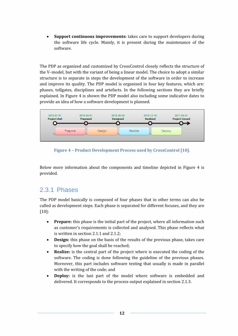
explained. In Figure 4 is shown the PDP model also including some indicative dates to
provide an idea of how a software development is planned.
Figure 4 – Product Development Process used by CrossControl [10].
Below more information about the components and timeline depicted in Figure 4 is
provided.
2.3.1 Phases
The PDP model basically is composed of four phases that in other terms can also be
called as development steps. Each phase is separated for different focuses, and they are
[10]:
Prepare: this phase is the initial part of the project, where all information such
as customer’s requirements is collected and analysed. This phase reflects what
is written in section 2.1.1 and 2.1.2;
Design: this phase on the basis of the results of the previous phase, takes care
to specify how the goal shall be reached;
Realize: is the central part of the project where is executed the coding of the
software. The coding is done following the guideline of the previous phases.
Moreover, this part includes software testing that usually is made in parallel
with the writing of the code; and
Deploy: is the last part of the model where software is embedded and
delivered. It corresponds to the process output explained in section 2.1.3.

13
2.3.2 Tollgates
As mentioned above, the PDP comprises four phases of software development. At the
end of each phase and at the beginning of the PDP, the CrossControl’s process provides
tollgates that are a sort of check points to verify whether the activities done in a certain
phase are approved or not. These points serve mainly to have evaluation criteria of
what has been done until a certain development time. In total, they are five as
described in the following [10]:
Project Start: is the check in which is verified and evaluated the feasibility of
the project in accordance with the requirements specification, and if the presale
activity exists and has sufficient quality level;
Prepared: is the check in which is evaluated if the project is properly
described, with the aim to run the project in a deterministic way. At this stage,
there are not ambiguous project-specifics and almost all limits of the project are
known;
Designed: is the check of the project in order to evaluate how the software
should be developed by considering the challenge among expected results, time
and budget;
Realized: is the check to verify if the software has been properly designed and
if the development results match the expected results; and
Project closed: is the check that takes care to verify and validate the quality of
the output of the developed software.
2.3.3 Disciplines
Disciplines are the different works that are done during the PDP. The PDP designed by
CrossControl provides three categories of disciplines such as:
Common disciplines: are the disciplines that are common between the
hardware and software;
Hardware disciplines: are the disciplines relative to the hardware
development; and
Software disciplines: are the disciplines relative to the software development.
In Figure 5 is shown the full lists of the PDP’s disciplines [10].

14
Figure 5 – Lists of CrossControl’s PDP disciplines.
Since this report mainly focuses on software development, the hardware disciplines are
not taken in consideration into the following explanation [10]:
Project Management: is the discipline of planning, organizing, securing, and
managing resources to achieve specific goals (time, material and other stuff);
Product Documentation: is the discipline of writing the documentation to be
delivered to customers (tutorials, user manuals, etc.);
Configuration and Change Management: is the discipline to maintain
consistency between the product’s performance, functional and physical
attributes with its requirements, and maintain flexibility to shift individuals,
teams and organizations from the current state to a future one;
Requirements: is the discipline that takes care to evaluate in depth the
requirements specification;
Safety Management: is the discipline that involves all activities and
documentations related to the safety level management of the project;
Life Cycle Management: is the discipline that takes care to provide the basis
and instructions for correctly managing all development phases;
Analysis and design: is the discipline that provides guidelines to analyse the
requirements with the aim to define a proper software architecture;
Implementation: is the discipline that takes care to implement the software
starting from the previous analysis and design. In this discipline is also included
the Unit testing of software components; and
Verification: is the discipline that takes care to perform testing with the aim to
verify and validate the software.

15
2.3.4 Artefacts
Artefacts are the output produced at the end of the development process. With respect
to the general system engineering process described above, these artefacts correspond
to the outputs produced by the Process Output. After the testing phase, the software is
embedded and all the artefacts related to the software are also produced, such as
documents, drawings, design models, reports etc. [10].
In order to make software artefacts as correct as possible in terms of verification and
validation, several testing methods are exploited during the development process as
corresponding to selected testing methodologies. In the following sections an overview
is provided about the most used testing methods and techniques in CrossControl,
Bombardier Transportation and Volvo Construction Equipment.
2.4 Testing Techniques
One of the fundamental phases of software testing is its instrumentation, which is the
design and creation of efficient test cases, with the purpose to cover all possible
features of the program. In this respect, a specific analysis has to be done with the
purpose to identify representative test cases able to cover all the available behavior
alternatives the produced software can show. Typically that activity is time-consuming
since it demands a deep knowledge of the SUT. As mentioned above, it is practically
impossible to obtain error-free software systems, and this is especially true for complex
systems. In this respect, the purpose of a good testing is to discover as much problems
as possible in order to reach the desired level of quality.
In Figure 6 is shown a graph that puts in relation three different kinds of defects the
software is affected by during its development progress. The green line is relative to
the progress of the total number of defects detected in the software in a certain period.
The blue depicts the predicted defects in a certain period and its progress is Gaussian.
The red line draws open defects1 of the software during the software testing in a
certain period. Although it changes frequently with the time, it is can be categorized
with a Gaussian progress.
1 Open defects are all bugs that have been discovered during the life cycle of the software and have already
been notified to the developer. Usually, they are more numerous during the testing phase and generally they are detected with existing testing techniques.

16
Figure 6 – Defect trend analysis: total number of detected defects over time [12].
Software testing is the process of executing programs or applications with the intent of
finding bugs (errors or other defects). It specifies methods that in general are split in
two major categories, “Black–Box” and “White–Box”. The White–Box method is also
known as clear–box. The main purpose of the test cases execution is to analyse the
effects that they produce on the SUT. In Figure 7 is shown the comparison between
Black–Box and White–Box methods.
Figure 7 – Comparison between Black–Box and White–Box methods.
The main difference between these methods is that Black–Box testing is performed at a
high level, which means that testers do not need to know the system in detail, as for
example the knowledge of the application source code; whereas for the White–Box
method testers have to deeply know the source code and the behaviour of each single
component of the system. Usually, the White–Box testing seems to be more accurate
and precise because it looks in depth (performed on each single software component),
even though the creation and execution of test cases takes more time because of the

17
accurate analysis of the system. The advantage of this kind of testing is that it is the
only kind of test that can be used during the development process, since it uses the
source code; whereas its disadvantage with respect to the Black–Box testing is that it
cannot be used on the final software (system). In Figure 8 is shown how a system
testing is fragmented in accordance to the software structure and which kind of method
can be used at a certain layer of the hierarchy.
Figure 8 – Hierarchical testing in a fragmented system [13].
2.4.1 Black–Box Testing
Definition 5 – “Black–box testing (also called functional testing) is testing that ignores
the internal mechanism of a system or component and focuses solely on the outputs
generated in response to selected inputs and execution conditions” [3].
The execution of Black–Box tests, likewise to the White–Box is done by means of
selected test cases on the basis of functional requirements or design specification of the
SUT.
Typical Black–Box test design method includes:
Decision table testing: is a technique based on a table in which are
represented all possible alternative states the software can assume during the
execution of a certain action on the basis of specific conditions;
All–pairs testing or pairwise testing: is a technique that usually is associated
to an algorithm with the aim to provide combinatorial software testing. It takes
in input a pair of values and tests all possible discrete combinations of those
parameters. If the algorithm is used carefully for each software functionality,
the verification test results exhaustive and fast;
State transition tables: is a technique based on the state transition table, in
which are represented states and events. States represent the exact position of
execution of the software, and they are shown as current state and next state;
whereas the events are transitions between states;

18
Equivalence partitioning: is a technique that takes in input a set of values and
divides it in valid and invalid partitions. These values are provided in input to
the software to verify if the produced output conform to the expected values;
and
Boundary value analysis: it is based on the equivalence partitioning; indeed it
takes in input a set of values, and divides them in valid and invalid partitions.
Differently from the previous technique, in this case only the minimum and
maximum value of each partition is tested. This technique is more efficient in
terms of performance and test completeness with respect to the equivalence
partitioning.
2.4.2 White–Box Testing
Definition 6 – “White–Box testing (also called structural testing and glass box testing) is
testing that takes into account the internal mechanism of a system or component” [3].
As mentioned above and illustrated in Figure 7 and Figure 8, White–Box testing is
based on the verification of each single software entity, which means that each test case
is made ad–hoc for testing each singular software component. Test case execution is
done by programmers who choose inputs and drive the execution with the purpose of
determining the correctness of the output.
White–Box testing method includes [14]:
Basis path testing: is a method that allows programmers to drive a logical
complexity measure of testing for the determination of linearly independent
paths and hence try to cover as much execution paths as possible the software
can assume during the execution. This method exploits the source code to
synthesize a flow graph of the software;
Control structure testing: is an optimal version of the basis path testing. Basis
path testing is very easy to implement, although it results to be not completely
efficient. Control structure testing fills such lack of efficiency the following three
refinements:
o Condition testing: is a method that analyses the source code and takes
care to cover all possible conditions the software execution can assume;
o Dataflow testing: is a method in which test cases are selected
according to the use of variables and definitions in the software; and
o Loop testing: is a method that tests specific chunks of code that
represent cycles. It is useful since in general algorithms contain cycles,
and most of the bugs are detected in them. Loops can be defined in four
classes, such as simple loops, concatenated loops, nested loops and
unstructured loops.
Programming technique testing: is a method that is known as performance
testing because thanks to the use of profilers or hardware–based execution
monitors it measures the performance of the program during the execution of

19
software modules. Moreover by means of this method is also monitored
resource usage at the operating system level, such as memory, CPU, disk,
network, etc.; and
Mutation testing: is defined as a change/evolution of the software. This
method is tailored to the verification of the completeness of test cases with
respect to mutations of software. Moreover, it can be exploited as an indicator
of the reliability of previous test results.
2.5 Testing Methods
Testing is part of every stage of the software life–cycle, and moreover is done at each
level of software development on the basis of different natures and objects. Nowadays,
programming techniques have evolved towards modularized approaches that try to
maximize the use of e.g. APIs, libraries, etc. Such re-usable software modules, called
components, have the advantage of being well-designed and tested, such that they can
be considered as bug-free. In this way, a complex software system can be decomposed
by means of smaller sub-systems, typically associated with corresponding sub-
problems, and the final system can be obtained as resulting from the composition of
those re-usable software units (or entities).
In order to better understand this development approach, let us think about building a
puzzle. Starting from many small pieces that in this case represent software
components, the aggregation of some pieces of the puzzle could be called sub–puzzle
that is a part of the entire one. Usually, if the puzzle size is large it is convenient to
proceed by assembling several sub-puzzles that in this case represent sub–systems.
Then, the union of them forms the entire puzzle that in the software realty is the entire
system.
In Figure 8 is possible to better understand how systems are fragmented. Thanks to
this approach is possible to gain several benefits, both from the programming and
testing points-of-view. For the former, the benefits are mainly devoted to time and
money saving. They are summarized as follow:
Reusability: possibility to use already existing components thus allowing a
faster delivery;
Maintainability: simplified management of software features, since they can be
analysed singularly;
Efficiency: the use of standard components, such as APIs, libraries, etc. or
personal components that are already highly tested, improves the performance
of the software execution due to the optimization of them;
Reliability: as for the previous, the use of existing software components can
dramatically reduce the likelihood of bugs, thus improving the confidence of the
software; and

20
Portability: since components are considered parts of code that perform
simple operations, they usually can be quickly and easily rebuilt for a new
platform without affecting any other component.
On the testing side, the main benefits of which developers and testers can enjoy are the
possibility to test the software step–by–step during the development in order to create
a program that is more reliable and consistent. In fact, starting from single software
components it is possible to test them by means of a specific kind of test, called “Unit
testing”; whereas it is possible to test the aggregation of components, often called as
components integration with the “Integration testing” technique. In order to complete
the testing family, the last type of testing is the “system testing” to verify the entire
system.
In Table 1 the different types of software testing are summarized.
Testing Type
Specification General Scope Opacity Testing
Performer
Unit Low–Level Design
Code Structure
Small units of code (no larger than a
class) White–Box
Programmers who wrote the
source code
Integration Low–Level Design High–Level Design
Multiple classes White–Box Black–Box
Programmers who wrote the
source code
System Requirements
Analysis
Whole product in representative environments
Black–Box Independent
testers
Table 1 – Different levels of Software Testing [15].
System, Unit and Integration testing are types of testing that include many different
testing techniques. These latter are organized in two big categories that are [16]:
Functional testing: testing based on an analysis of the specification of the
functionality of a component or system; and
Non–functional testing: testing the attributes of a component or system that
do not relate to functionality.
In Table 2 and Table 3 are represented some functional and non–functional testing
techniques that are usually used during the software development.

21
Functional Testing
Unit
Integration
System
HIL
Acceptance
Regression
Reliability
Retesting
Ad–hoc
Smoke
Table 2 – Example of functional testing techniques.
Non–Functional Testing
Fault Injection
Compatibility
Performance
Portability
Scalability
Usability
Security
Volume
Stress
Load
Table 3 – Example of non–functional testing techniques.
According with the focus of this paper, only some of these techniques are below
explained in detail, notably Unit, Integration, System, HIL and Fault Injection.
2.5.1 Unit Testing
In software development, source coding is done in parallel with its verification. The
purpose of Unit testing is to create test cases ad–hoc for all functions and methods of
the source–code for detecting the presence of bugs or other defects. If during the
testing phase some inconsistences in the code are found, which means that some test–
cases failed, programmers operate refactoring of the source code correspondingly.
Definition 7 – “Code refactoring is disciplined technique for restructuring an existing
body of code, altering its internal structure without changing its external behaviour" [17].
Afterwards the execution of test cases and the refactoring of the code, test cases are
incrementally and iteratively adapted to newly added code. This procedure of testing
continues until all test cases are successfully completed, so that it can be asserted that
there are no bugs in the source code. As expected, the successful completion of the tests
does not guarantee the source code to be bug free, since for instance test cases could be
incomplete of not properly designed.
The phase of re–running all test cases that have been successfully or not in the previous
interactions is also known as “regression testing”.
Definition 8 – Regression testing means “Rerunning test cases which a program has
previously executed correctly in order to detect errors spawned by changes or corrections
made during software development and maintenance” [18].

22
The creation of test cases can occur by means of two different approaches. The former
that programmers have to write test cases after coding; whereas the latter approach,
also called “Test–Driven Development” (TDD), is based on the specification of software
requirements as the tests the system has to pass in order to be considered as
successful. As a consequence, by means of a TDD approach the source code is not
exploited as basis to derive test cases.
Even if this approach could sound strange because the writing of the code occurs after
the writing of test cases, it brings some important advantages, such as [19]:
Writing of test cases directly based on requirements;
Reduction of time in rework;
Fast feedback of the source code that has been written;
Pre–feedback about some development incongruences before the writing of the
code;
Fast re–testing of the code during the evolution of software;
Support to developers for keeping a good structure of the source code; and
Improvement of the quality and reduction of bugs.
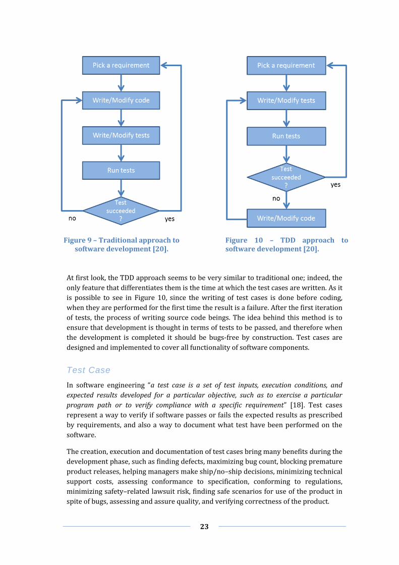
In Figure 9 and Figure 10 are shown two transitional state diagrams to compare both
approaches.
23
Figure 9 – Traditional approach to software development [20].
Figure 10 – TDD approach to software development [20].
At first look, the TDD approach seems to be very similar to traditional one; indeed, the
only feature that differentiates them is the time at which the test cases are written. As it
is possible to see in Figure 10, since the writing of test cases is done before coding,
when they are performed for the first time the result is a failure. After the first iteration
of tests, the process of writing source code beings. The idea behind this method is to
ensure that development is thought in terms of tests to be passed, and therefore when
the development is completed it should be bugs-free by construction. Test cases are
designed and implemented to cover all functionality of software components.
Test Case
In software engineering “a test case is a set of test inputs, execution conditions, and
expected results developed for a particular objective, such as to exercise a particular
program path or to verify compliance with a specific requirement” [18]. Test cases
represent a way to verify if software passes or fails the expected results as prescribed
by requirements, and also a way to document what test have been performed on the
software.
The creation, execution and documentation of test cases bring many benefits during the
development phase, such as finding defects, maximizing bug count, blocking premature
product releases, helping managers make ship/no–ship decisions, minimizing technical
support costs, assessing conformance to specification, conforming to regulations,
minimizing safety–related lawsuit risk, finding safe scenarios for use of the product in
spite of bugs, assessing and assure quality, and verifying correctness of the product.

24
An example of how a test case is documented is shown in Table 4.
Test case ID: <number>
Date: <yyyy–mm–dd>
Version: <number>
Author: <name>
Reviewed by: <name>
Used in: <system name>
System version: <number>
Test environment: <reference>
Test Suite: <number>
Automated <yes/no>
Time for TC creation; <minutes>
TDT used: < name >
Assumptions:
Starting point: Test case: Pre–condition: Step 1: Step 2: Step n: Input Data (valid) Input Data (invalid) Output/visible result for passed: (post–condition) Side–effect (clean–up) Comment:
Table 4 – Example of a test case template.
2.5.2 Integration Testing
With respect to Table 1, Integration Testing is located at the second level of software
testing. It comes as a logical consequence of Unit testing and is considered as a phase of
transition between Unit testing and system testing. Usually this kind of test is executed
in sub–systems where two or more units that have already been tested are combined
into components and the interfaces between them already tested [21]. This means that
even if all single units are well tested, during the integration of components could
emerge issues that cannot be detected by taking into consideration the single units. A
definition of Integration testing is given as follows:
Definition 9 – “An orderly progression of testing in which software elements, hardware
elements, or both are combined and tested, to evaluate their interactions, until the entire
system has been integrated” [18].
Integration testing provides many different ways to perform the testing. Below are
shown some of the most popular common methodologies [21] [22]:
Big Bang: is an approach that prescribes that all or most of the components are
integrated between them to complete the system or large sub–system before
testing the result. This kind of approach can be is very efficient for saving time,
but at the same time in case of detection of defects does not provide a fast and
easy method to fix failures. The slow resolution and big effort to solve problems

25
is due to the high complexity of the case study. A type of Big Bang testing
method is called usage model testing which is used for software and hardware
Integration testing.
Top–Down: is an approach to perform the testing where the integrated
components located at the top–level are tested and integrated first (top). Step–
by–step the testing continues entering in detail in sub–systems until reaching
the bottom level that is represented by single components (down);
Bottom–Up: is an approach in which the testing process is similar to the
previous one, but with the difference that in this case it begins from single
components (bottom) and continues up to the complete integration of all
components involved in the sub–system (up); and
Sandwich: is an approach that is also known with the name of “umbrella”. The
aim of this approach is combining the benefits coming from top-down and
bottom-up integration tests. In particular, it borrows the ease of finding bugs
from the former and the ease of discovering missing branch links from the
latter.
2.5.3 System Testing
System testing in accordance with Table 1 is located at the top–level of the hierarchical
scale. It means that it does work neither at the low–level design nor at the high–level
design, indeed this type of testing works only with the functional and technical
requirements that are the goals to reach to verify if the software meets them. System
testing can be considered as one of the last steps of the software development; in fact
through system testing it is possible to perform the final step of verifying the product
as a whole in a representative environment. In this phase is possible to detect defects
due to the integration between sub–systems or components inside a sub–system. A
definition of system testing is given as follows:
Definition 10 – “The testing of a complete system prior to delivery. The purpose of system
testing is to identify defects that will only surface when a complete system is assembled.
That is, defects that cannot be attributed to individual components or the interaction
between two components. System testing includes testing of performance, security,
configuration sensitivity, start–up and recovery from failure modes” [18].
System testing is considered as a crucial step in quality management process that
enables testers to verify and validate the application architecture as well as the
requirements [23]. Differently from Unit and Integration testing where programmers
execute tests, in this case the task is accomplished by testing experts. The testing phase
is done with the scope of Black–Box testing, therefore it is not required for testers to
have a deep knowledge of the source–code or logic for testing the application [24].
Relevant factors that are part of the success of the testing are various, such as [23]:
26
Test coverage: is a measurement that is done to evaluate how much software
has been exercised by tests or in other words how many functionalities of
software have been tested. Test coverage is a general category with which are
indicated all activities concerning many different types of coverage, such as
code coverage, feature coverage, scenario coverage, screen item coverage and
model coverage;
Defect tracking: takes trace of all defects that have been found in software
during the execution of test cases. After fixing these defects, in the following
execution of test cases is verified that previous defects are not present any
more. After the refactoring of the code and the re–adaptation of test cases, the
failure of one or more test cases which failed previously highlights a wrong
refactoring or re–adaptation;
Test execution: is an important factor that provides the right execution of test
cases in order to improve the level of confidentiality with the testing;
Build process automation: since many bugs are detected during the testing
phase due to an erroneous building procedures, the automation of this process
helps to avoid both false-positive and false-negative detections, minimise risks,
improve the quality and speed up bug fixing. “Build means the compilation of
the various components that make the application deployed in the appropriate
environment” [23];
Test automation: is a very powerful process for the automation of the
execution of test cases. It bring many benefits, including the improvement of the
testing quality avoiding human errors during the execution, speed–up of the
execution and possibility to re–execute the entire test suite more times thanks
also to the time saved; and
Documentation: testers have to carefully take trace of all operations they are
performing; in fact, in case of defects a detailed report must be written and
delivered to programmers. The information carried by a report is about the
kinds of defects, preconditions, current conditions, list of performed steps, etc.
Generally the report is done to help programmers to discover failures as quickly
as possible, hence report contents should be easily matchable with the
corresponding software portions. In addition, it is useful to take trace of all
problems that have been detected in the program.
System testing is considered as a collection of a wide range of tests that can be
performed on a system. Through them it is possible to verify the entire system even if it
remains always strictly connected to the development process and therefore to a
virtual environment. In order to test the developed system in a real environment
another specific testing technique that is adopted is called HIL.

27
2.5.4 Hardware–In–the–Loop Testing
In the previous section some techniques have been shown for testing the software during
the development process. If done appropriately, those tests can provide reliable results
about the correctness of the system under development. However, especially Unit and
Integration testing are closely related to coding activities and typically abstract from
the real environment in which the software will be deployed. Even system testing, that
tests the software system as a whole, is performed in a simplified deployment
configuration, which cannot completely represent a real environment.
The immediate consequence of the gap between the testing deployment environment
and the real one is that unknown and unforeseen defects can come out only when the
system is executed in the real environment. Typically, such problems are due to
conditions that have been consciously or unconsciously ignored when testing the
system in the virtual environment. In order to overcome this issue, the ideal approach
would be to perform test cases during the execution of the software in the real
environment. Unfortunately, the ideal solution is very often not applicable, due to costs,
impossibility to have a real environment, etc. A good solution to mitigate this latter
issue is the use of a simulated real environment by adopting the HIL testing.
HIL is a kind of testing able to simulate the real environment to perform test cases
during the development process, enabling testers to accurately verify software. HIL
simulation is a technique used for the development and testing of complex real–time
embedded systems, and it promises to improve the quality and reliability of the
software. As understandable by the name of this technique, in this case for the
verification and validation of the software is based on a hardware that is able to
virtually emulate the real environment where the software should work. HIL differs
from pure real–time simulation due to the addition of a real hardware component in
the loop that often is called Electrical Control Unit (ECU) [25].

28
Figure 11 – Typical HIL test system [25].
In Figure 11 is shown a typical HIL system. It mainly comprises four sub–systems that
are Host PC, Real–time simulation hardware, Signal adaptation and fault simulation
hardware, and ECU. An overview of all components involved in the system is provided
in the following [25]:
Host PC: is the sub–system used to provide the GUI to communicate with other
sub–systems. It is directly connected to the simulated environment to run the
test automation applications with the aim to simulate the real software
execution in a real world. Moreover, the GUI provides the diagnostic
communication with the ECU and the control of the HIL system, allowing the
handling of the fault injection. Usually, in systems dedicated to vehicles, the link
between the Host PC and the Fault Matrix is implemented using the Controller
Area Network (CAN);
Real–time simulation hardware is the simulated sub–system that represents
the real hardware, which is a plant model. This latter, differently to usual
personal computer operating systems is typically designed to work in real time.
Plant model is connected to the ECU and its main role is to simulate the real
environment providing information (values) of electrical stimuli, which are for
example generated by sensors and actuators. This simulation is useful for fully
exercising the ECU and creating behaviours that often can result unusual in a
real environment with the aim to stress the software with usual and unusual
tests;

29
Signal adaptation and fault simulation hardware are composed by three
components, which are:
o Signal Amplifiers: is the component that provides current to I/O boards,
since they are passive instruments that are not able to source or sink
current;
o Load simulation: is the component responsible of loading the simulation
of the system; and
o Fault Matrix: is the component used to test fault detection capabilities.
As mentioned in the previous subsystem, in HIL systems are often
performed tests that are related to unusual conditions. This is done
because a software system must be robust when there are unforeseen
situations, for example hardware malfunctions.
ECU is the embedded system that controls electrical systems or sub–systems of
a real system.
To have a better understanding of how all components in Figure 11 are represented in
reality, below a simple example is provided about a car software development
environment.
The Host PC represents the board computer installed inside the passenger
compartment to provide information to the driver about the oil, water, fuel, suspension,
wheels, roll, pitch, etc. [26]. The HIL system represents the electronic plant of the car,
which is responsible to detect all values taken under control from the vehicle and
forward them to the board computer. The ECU is the part of the car system that is
responsible to handle information of sensors and actuators such as electric signals, and
deliver them to the HIL system as digital signals.
The benefits brought by HIL testing are many. The most important are the cost saving,
time saving, safety and feasibility. Time saving and safety are typically related to a cost
measure [27]. In fact, by testing the electronic plant on the simulated environment not
only allows to save the costs of buying a real car, but it also permits to explore the
system behavior in disparate conditions such as the characteristics of the road, the
mechanical parts, etc. Moreover, some sub-systems are intrinsically expensive to test,
notably the airbag or the ABS plant, since it would require to potentially causing
irreversible damages to the tested system. A simulated environment makes also it
possible to save time by enabling the quick testing of many different states that the
electrical plant can assume. Furthermore, the duration of development and tests affects
the time–to–market for a planned product. With respect to safety aspects, a simulated
environment allows to reproduce multiple critical conditions without harming the life
of testers. Another relevant advantage of exploiting a simulated environment is the
feasibility of the test itself. In fact, in many cases it is too expensive/dangerous or even
impossible to reproduce particular testing scenarios, while they can more easily be
built on purpose in a simulated environment.

30
After this brief discussion about HIL testing, and how, where and when it is applied, it
should be more evident why this kind of testing is very functional and important for the
development life cycle.
In addition to what has been said, HIL testing is seen as a technique that results to be
useful to [27]:
Enhancing the quality of Testing;
Tight development schedules;
High–burden–rate plant; and
Early process human factors development.
As mentioned in the Signal adaptation and fault simulation hardware sub–system, there
exists a component that takes care to provide fault cases to the system with the
purpose to generate failures that contribute to the increment of the software
robustness and dependability. In the following section an overview of the Fault
Injection testing technique is presented.
2.5.5 Fault Injection Testing
In software testing, fault injection is a technique that has been recognized as a powerful
instrument for improving the coverage of a test and to evaluate the dependability of
computer systems. It is a technique that dates back to the 1970s [28] and comes from
the fault injection that has been done at hardware level, called hardware implemented
fault injection.
In addition to the dependability, this technique is used to speed up the propagation and
the occurrence of faults into the system to verify how much the system is robust and to
evaluate the performance. According to what mentioned above, the propagation of a
fault generates the fault–error–failure cycle that is the key of the mechanism in
dependability [29].
Usually, Fault Injection testing is considered as a branch of the robustness testing that
is used to check the vulnerability of the component interfaces, communication between
interfaces and protocols. One of the most popular kinds of robustness testing is called
Fuzz testing, which is an automatic/semi–automatic technique that takes care to
provide invalid data to the SUT with the aim to increase the security [30].
Fault injection techniques are classified into two major categories: Compile–time
Injection and Runtime Injection.
Compile–Time Injection
The injection at compile–time is a technique where source–code is modified by
changing, adding or deleting some lines before the program image is loaded and

31
executed with the purpose to inject simulated faults into the software. Injection
generates a wrong compiled image of the software that consequently, when executed
by the system, activates specific faults. A simple example of how the behaviour of
software could be changed after the source–code compilation is shown below. In the
original source–code, since the value of the variable “a” is 5, the software will execute
the code within the “if” statement, whereas in the modified source–code, since the
relational operator has been altered the software will execute the code within the “else”
statement. One method that provides changes of existing lines of code is called
mutation testing.
Original source code Modified source code
int a = 5; if (a==5) { /* do something */ } else { /* do something else */ }
int a = 5; if (a!=5) { /* do something */ } else { /* do something else */ }
Runtime Injection
On the other hand, the injection at runtime is done during the execution of software
and consists in using a triggering of simulated faults at levels from the CPU registers
and the network [31]. Common mechanisms to inject faults are realized via physical
methods and triggers that can be implemented in different ways, such as [32]:
Time–out: is a method also known as “time based triggers” that uses time–outs
of the software to introduce faults. In practice, when a time–out is expired it
generates an interrupt to invoke fault injection. This method is simpler with
respect to other methods; indeed it does not provide either the modification of
the software;
Trap: is a method also known as “interrupt based triggers” used to generate an
interrupt at a specific place of the code or a particular event during the
execution of the software. Differently from the time–out, it can inject faults only
when certain conditions or events occur. An example of trap instruction could
be for instance the invocation of a fault injection before the access to a specific
CPU register; and
Code insertion: is a method much similar to the modification–code injection,
but with the difference that with this method is only possible to add
instructions at runtime rather than changing the original instruction.
The injection at runtime is a technique that uses a software trigger to inject faults into
the system during its execution. The injection of faults can be done through different
physical methods and triggers, such as:

32
Time Based Triggers: is a kind of injection associated to a timer. When a
certain time interval expires an interrupt is generated and the interrupt handler
associated with that specific timer shall inject the fault into the system; and
Interrupt Based Triggers: is a kind of injection based on hardware exceptions
and software trap mechanisms. They are used to generate interrupts during the
occurrence of particular events or when the software execution is performing a
specific operation in a certain place.
The two different triggers just mentioned above can use different techniques, such as:
Corruption of memory space: is applied to all memory spaces of the system,
such as CPU registers, Random Access Memory (RAM) and Input/Output (I/O)
memory locations;
Syscall interposition: is a technique that exploits the kernel of the operating
system to intercept system calls made by the software and inject faults into
them; and
Network level fault injection: is a technique that injects faults at network
level by corruption, loss or reordering of network packets.
Comparison of Fault Injection Categories
In Table 5 are shown the most important characteristics to compare the two types of
categories.
Compile–time Runtime
Cost Low Low
Perturbation Low High
Monitoring time–resolution
High Low
Accessibility of fault injection points
Register memory software Register Memory
I/O controller – port
Controllability High High
Trigger Yes Yes
Repeatability High High
Table 5 – Comparison between the two fault injection categories [32].
Tools Overview
Nowadays, research centres and companies have developed many tools to perform
fault injection. A list of the most popular tools is given below:
RESEARCH TOOLS

33
FTAPE (Fault Tolerance And Performance Evaluator) is a tool that has a
synthetic load unit which can simulate specific amounts of load for robustness
testing purposes, such as injection into memory, registers and disk [33];
Ferrari (Fault and ERRor Automatic Real–time Injection) is a fault injection
tool based on software traps activated by system calls or timers that inject
faults into a system [34];
MODIFI (MODel–Implemented Fault Injection) is a fault injection tool for
robustness evaluation of Simulink behaviour models [35];
DOCTOR (IntegrateD SOftware Fault InjeCTiOn EnviRonment) is a tools that
uses time–out, trap and code insertion in combination to inject faults [36];
LFI (Library–level Fault Injector) is a fault injection tool for testing robustness
of software to faults that originate in shared libraries and the layers below [37];
and
Xception uses advanced features of debugging and performance monitoring to
inject more realistic faults in the software [38].
COMMERCIAL TOOLS
beSTORM is an advanced tool with a relevant notably in aerospace, banking
and defence. It is a Black–Box testing and is based on the fuzzing technique.
Besides, it provides good algorithm focus on virtual attacks combination [39];
Holodeck is a tool known as simulator of the real–world application and
system errors for windows software and services. It use the fuzz testing during
fault injection [40, 39];
Codenomicon Defensics is an automatic framework that use the Black–Box
technique to do fault injection on different interfaces such as network
protocols, API interfaces, files, and XML structures [41]; and
The Mu Service Analyzer provides White–Box and Black–Box testing to
perform fault injection. It is widely known in the critical markets of network
operators and industrial control systems [42].
All kinds of testing presented until now bring many advantages to the development
process. One advantage that has been rarely renamed so far is the automation of
the test suite execution. This is a relevant property in terms of time because allows
test suite execution without step–by–step handling of programmers and testers and
because allows the fast re–execution of the complete test suite. Until today, testing
on software has been always manually driven because of the lack of automated test
execution processes. Nowadays, the necessity to automatize the execution of tests
for saving time and improve their quality, promotes testing automation as a hot
research topic. The following section illustrates of the automated execution of tests.

34
2.6 Automated Software Testing
Nowadays, computer systems are more and more present in our lives and often they
are used in safety–critical fields such as aircraft, industrial process control, health,
vehicle, etc. Daily, in these fields users are exposed to risks, therefore the involved
software must be guaranteed as safe, or in other words it must not carry by
malfunctions that could potentially affect safety [43]. As already mentioned in the
Introduction, the achievement of high software reliability such that it can be considered
as bugs-free requires a huge effort. Besides, as shown in Figure 6 and Figure 12, since
the effort is strictly related to the time consumed, the achievement of a high grade of
reliability takes much time. Lately, relevant research work has been devoted to
automated software testing, which promises to save the execution time of test cases,
and increase the dependability and coverage of SUT. Although these benefits are
tempting, as M.N. Alam mentioned in [44], it is improper to say that the automated
software testing is always time saving and more dependable. This because even though
there are many companies and researchers that are doing a huge effort to develop
reliable techniques, currently there are only techniques developed to be used in specific
cases, and therefore complicated to be adapted to other cases [44]. Bret Pettichord in
[45] illustrated some several problems that could affect automated software testing
during the development process, such as:
Spare time test automation;
Lack of clear goals;
Lack of experience;
High turnover;
Reaction to desperation;
Reluctance to think about testing; and
Technology focus.
These issues are mainly due to the experience of testers and premature testing
techniques.
Coming back to test automation, it can be defined as a development process which
creates a program to execute tests on other programs, that would be done manually
otherwise. One of the main problems affecting the creation of such testing programs is
that they are software themselves, and therefore could be affected by defects as well.
Nonetheless, when successfully implemented they disclose the opportunity to have
quick and reproducible test suites executions.
Mainly two approaches are defined for the test automation:
Code–Driven testing is a kind of testing based on the White–Box technique. As
its name implies, this kind of testing is done writing initially source code and
subsequently test cases for it. Code–driven testing is focused on source code

35
verification, therefore it enables testing on software components such as
function, classes, modules, libraries, etc.;
Graphical User Interface testing, differently from the previous approach, is
based on the Black–Box technique. Usually, it is based on automated testing
tools that provide a GUI and some advanced features. One of their most popular
features is called Record and Playback that enables users to record user actions
to create test cases and automatically play them with the aim to verify the SUT
behaviour.
2.6.1 Code–Driven Testing
In the last years a huge growth of software developments to practice automatic testing
has been done and the trend to use testing frameworks is higher and higher. One of the
most popular developer testing frameworks is known as xUnit that is built to support
TDD and is able to enclose simplicity of use, efficiency and alignment with framework
features [46]. xUnit is a collection of frameworks that was originally designed by Kent
Beck and known as SUnit to perform the testing on Smalltalk, whereas afterwards on
the basis of it have been developed a variety of frameworks for different languages,
such as JUnit (for Java), PHPUnit (for PHP), NUnit (for .NET), etc. [47]. From the name
of this collection is easily deductible that the “x” indicates the name of the language
supported by the kind of framework, instead “unit” indicates that these frameworks are
used to execute the code–driven testing on software units. The word “unit” derives
from unit testing. The relevant benefits of these frameworks can be summarized in the
no need to write tests many times and in the no need to remember what the expected
result of each test case is. The purpose of xUnit testing frameworks is to help testers
providing facilities to easily [48]:
Identify the better appropriate test method for the case in exam;
Identify tests related to classes, functions, libraries, etc.;
Provide constructs with the aim to perform pre–test, post–test, data–driven
tests and text–fixture; and
Handle the exceptions that are triggered by the software.
2.6.2 Graphical User Interface Testing
As opposed to code–driven testing, GUI testing is more simplified approach. It is done
GUI–driven which means that test cases are created at runtime while the application is
running. Therefore, only a little or no effort is required to testers to refine them by
means of extra coding. The precondition for this approach to be applicable is the
existence of a GUI for the application. A very important feature of this testing is the
possibility to be used not only on software applications, but also on websites for
example.

36
Selenium IDE [49] is an example of Integrated Development Environment (IDE) for
automating web applications testing purposes. It is an extension for the Firefox
browser that allows the automatic registration of scripts in Selenese language
(scripting language for Selenium) during the exploration of web pages. In the scripts
are saved all interactions that testers done during the navigation, such as clicks,
selecting options, filling out fields, etc. [49]. In addition, the scripts can be modified to
improve their trustworthiness. After the registration, for each script is created a test
case that is performed during the execution of the website (runtime). Since also the test
cases are performed through the GUI testers can see step–by–step all the operations
done, such as clicks, kinds of input passed to text fields, etc. Usually the operation of
registration and execution of scripts is called “record and playback” [50]. Nonetheless,
there exist GUI testing variants that are scriptless and do not provide record and
playback.
In this report it has been mentioned several times that the reliability of testing strictly
depends on the coverage of test cases. In other words, tests have to be chosen in a way
such that they are able to explore all the possible behavior of the software. In this
respect, the test coverage measures the amount of system behavior explored by the
corresponding test cases, and is discussed in more details in the next section.
2.7 Test Coverage
Test Coverage is a term used in software testing that refers to how much software has
been exercised by a test suite. The measure of the ratio between test cases coverage
and programs is expressed as percentage. This measure is very useful for testers to
have an idea about how much the SUT is covered by test cases. A study by Mockus et al
in [51] demonstrates that the testing effort increases exponentially with respect to its
coverage level, but at the same time also the presence of defects in the software
decreases linearly. A direct consequence of such interplays is that the higher is the test
coverage, the higher is the dependability of the software. “This suggests that for most
projects the optimal levels of coverage are likely to be well short of 100%” [51].
A couple of graphs that correlate the coverage percentage of test cases and failures
discovered in the program with the effort (expressed in time) spent to improve and
increase test cases are shown in Figure 12.

37
Figure 12 – Coverage and Failures rate for high and low productivity [52].
Test coverage can be considered as a collection of many kinds of coverage measures,
such as:
Code coverage;
Feature coverage;
Scenario coverage;
Screen item coverage; and
Model coverage.
To maintain the focus of the thesis on the development and testing of the code, in the
following section is shown a broad overview of code coverage.
2.7.1 Code Coverage
Code coverage is a White–Box testing technique also known as structure testing, which
has the purpose to take care of finding all areas of the source–code that are not
executed by a set of test cases. The goals of this evaluation can be the extension and
improvement of test cases in order to increase the coverage, to determine a
quantitative measure of code coverage, to identify redundant test cases that do not
increase the coverage, etc. [42] [52].
Code coverage provides a wide variety of fundamental metrics to evaluate the
coverage. Below is listed a selection of the known metrics with a hint of their
advantages and disadvantages:
Statement coverage is also known as line coverage, segment coverage or basic
block coverage. It indicates the code lines that have been executed in the
program and how much is the coverage percentage of test cases with respect to
the source–code. The advantage of statement coverage is its simplicity about its

38
application, and with respect to other metrics, here the percentage coverage is
related to the percentage of discovered faults. The disadvantage of this metric is
its insensitivity to some control structures;
Decision coverage is also known as branch coverage, all–edges cover or
decision–decision–path testing. Basically this metric is related to condition
coverage, but with the addition of coverage for switch–statement cases and
exception handlers. Moreover, it takes care to verify whether condition
coverage evaluated accurately both conditions (true and false) for the if–
statement and while–statement;
Condition coverage indicates the conditions that have been executed in the
program (e.g. Boolean conditions) and the percentage of test case coverage with
respect to conditions. The disadvantage of the condition coverage “is that it
might ignore branches within Boolean expressions due to short–circuit
operators” [53];
Condition/Decision coverage is the join of the main characteristics of
condition coverage and decision coverage. One of its advantages is the
achievement of a good result with simplicity;
Modified Condition/Decision Coverage (MC/DC) is an extension of the
Condition/Decision coverage that is often used in safety–critical applications. In
addition to the previous criterion it enhances the coverage by requiring that
each element of the condition must be evaluated independently. The
independent evaluation ensures that all possible variants of the condition are
tested. Below is shown an example based on a java statement to highlight the
difference between the two criteria:
If ((varA || varB) && varC) { }
The Condition/Decision criterion is satisfied by the following conditions:
o varA = true, varB = true, varC = true;
o varA = false, varB = false, varC = false.
MC/DC is not satisfied by the following conditions because in the first condition
varB is not evaluated and in the second condition varC does not influence the
decision. For a correct evaluation of this statement with the MC/DC criterion
the following conditions must be taken in consideration:
o varA = false, varB = false, varC = true;
o varA = true, varB = false, varC = true;
o varA = false, varB = true, varC = true;
o varA = true, varB = true, varC = false.
Multiple condition coverage: is based on the condition coverage metric and it
reports whether every possible combination of the condition occurs. This
metric, even if appearing as accurate about the verification of conditions, can
meet several computational issues during the evaluation of complex Boolean
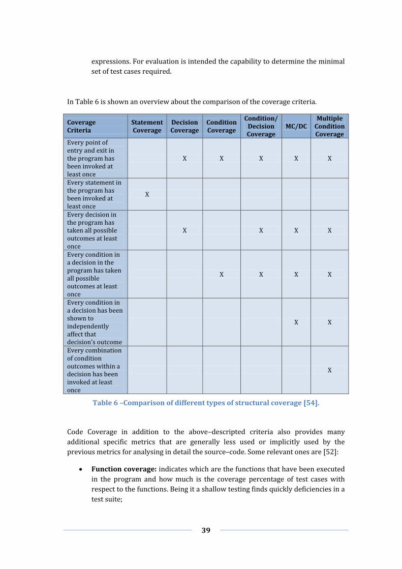
39
expressions. For evaluation is intended the capability to determine the minimal
set of test cases required.
In Table 6 is shown an overview about the comparison of the coverage criteria.
Coverage Criteria
Statement Coverage
Decision Coverage
Condition Coverage
Condition/ Decision Coverage
MC/DC Multiple
Condition Coverage
Every point of entry and exit in the program has been invoked at least once
X X X X X
Every statement in the program has been invoked at least once
X
Every decision in the program has taken all possible outcomes at least once
X X X X
Every condition in a decision in the program has taken all possible outcomes at least once
X X X X
Every condition in a decision has been shown to independently affect that decision’s outcome
X X
Every combination of condition outcomes within a decision has been invoked at least once
X
Table 6 –Comparison of different types of structural coverage [54].
Code Coverage in addition to the above–descripted criteria also provides many
additional specific metrics that are generally less used or implicitly used by the
previous metrics for analysing in detail the source–code. Some relevant ones are [52]:
Function coverage: indicates which are the functions that have been executed
in the program and how much is the coverage percentage of test cases with
respect to the functions. Being it a shallow testing finds quickly deficiencies in a
test suite;
40
Path coverage: indicates what are the paths that have been executed in the
program and how much is the percentage of test cases with respect to all
possible paths. Since path coverage takes care to verify paths, in loop cases only
a limited number of them are taken in consideration;
Data flow coverage: “is a variation of path coverage considers only the sub–
paths from variable assignments to subsequent references of the variables”
[52]. A couple of disadvantages of this metric are the complexity and no
evaluation of the coverage condition;
Entry/exit coverage: is also known as call/return coverage. It indicates which
are the calls and returns that have been executed in the program and how much
is the coverage percentage of test cases with respect to all calls and returns;
Object code branch coverage: is a metric that is very accurate to discover all
branches in software due to the use of the compiler, since the latter during the
compilation can create objects that are not directly visible by the source–code.
The result of this coverage is more related to the provision of information about
the compiler rather than on the program structure;
Linear code sequence and jump coverage: is a variant of the path coverage
that takes in consideration only sub–paths that can be represented from the
source code without taking into consideration the flow graph;
Loop coverage: is a detailed metric that takes care to analyse well all kinds of
loops in the source–code, such as do–while, while, for, etc.;
Race coverage: is relative to the problem of threads synchronization. It mainly
analyses if there are threads that execute the same code at the same time. This
metric is widely used for testing multi–thread software;
Relational Operator Coverage: indicates whether there are mistakes in the
source–code related to relational operators and whether boundary situations
occur;
Weak Mutation Coverage: is similar to the relational operator coverage
although it is more general. In addition, this metric provides the evaluation of
arithmetic operands; and
Table Coverage: indicates whether all locations of arrays are well referenced.

41
3 Survey of Existing Test Notations and
Tools
3.1 General Notations
In software engineering during the last years many notations of different types have
been standardized. The most important existing test notations are listed in the
following [55]:
Record–Playback Scripting is a notation that encloses all tools able to perform
testing using the record and playback technique. This technique is well known
in web applications testing. The creation of test cases is very easy since
programmers/testers need only to browse the functionalities a web site is
expected to offer through the GUI. In fact, an underlying mechanism is in charge
of automatically generating corresponding test cases as the web application is
used. All records are converted into test scripts that are executed afterwards.
Usually the registration of test scripts is made though a GUI, however there is
also the possibility to manually create or modify test cases. In section 2.6.2
general information about the Selenium tool is provided;
Standard Scripting is a notation that groups all tools able to describe test cases
in standard scripting languages, such as PHP, VBScript, Ruby, Python, etc.
Additionally, these tools may provide some functions or libraries oriented to
testing in order to take advantage of user interface;
XML–based is a notation that encloses all tools able to describe test cases in a
XML document, which is afterwards parsed by a XML parser. Testing
instructions contained in the document are executed on the SUT;
UML Testing Profile is a widely known standardized modelling language in
object–oriented software engineering field. It is a notation that extends the UML
language in order to enable the description of tests. An example of tool that uses
this kind of approach is JUnit; and
FIT is a notation that encloses all tools based on FIT, which is an open–source
tool for automated software tests invented by Ward Cunningham. This notation
includes many variants that support keyboard–driven and data–driven testing.
Another well-known testing notation is TTCN-3. Since it has the potentials to be
adopted by CrossControl in its development process, we dedicated a specific section of
this report to a deeper explanation of its characteristics. Therefore, for more
information about TTCN-3 the reader is referred to Section 3.2.

42
3.1.1 Testing Tools
Nowadays on the market there is a vastness of automated testing tools, whose purpose
is to provide a better user experience in terms of creation, management and execution
of tests for any desktop, web or rich client software. Moreover, as also mentioned in the
previous sections, these tools promise to make a test more reliable and less expensive,
and speed up the functional and regression testing.
The systematic survey of automated testing state-of-the-art involved the selection and
evaluation of twenty eight tools (open–source and commercial) on the basis of well-
defined criteria notably supported testing types, supported scripting languages, IDE’s,
application environments, operating systems, hardware requirements, supported
protocols, availability of extensions or plug–ins, license and price. A complete overview
of the comparison of these tools is shown in Appendix A.
In the following the list of selected testing tools is shown.
AutoIt [56] is a freeware scripting language developed by Jonathan Bennett &
AutoIt Consulting for automating the scripting generation for Microsoft
Windows software by means of a GUI;
C/C++TEST [57] is an integrated solution developed by Parasoft, which allows
the automation of testing techniques and methods. It promises to improve the
dependability of software developed in C/C++ due to test facilities, such as
static analysis, peer code review, Unit testing and runtime error detection;
Certify [58] is a next–generation functional testing solution developed by
Worksoft. It increases performance and agility to Systems, Applications and
Products (SAP) by automating end–to–end testing;
dotTEST [59] similarly to C/C++TEST tool this is an integrated solution
developed by Parasoft, tailored to testing applications developed in .NET (C#,
VB.NET, ASP.NET and Managed C++);
eggPlant [60] is a cross–platform automated testing tool from TestPlant to
automatize and perform Black–Box testing on any platform, technology or
browser that is connected to it through the Virtual Network Computing (VNC);
FitNesse [61] is an integrated standalone wiki and acceptance testing tool
written in Java by Robert C. Martin et al, and distributed under Common Public
License (CPL). It supports several languages such as Java, C++, Python, Ruby,
Delphi, C#, etc.;
HP Unified Functional Testing [62] is an automated functional defect testing
solution that speeds up software testing automation for GUI and API
applications. It is developed by Hewlett–Packard Software Division and is a
combination of HP QuickTest Professional and HP Service Test software;
LabVIEW [63] is a powerful system design platform and development
environment for a visual programming language built specifically for engineers
and scientists, and developed by National Instruments. It is a cross–platform
tool designed for data acquisition, instrument control, and industrial
automation;

43
Maveryx [64] is a freeware open–source automated testing tool to test Java
applications. It is designed by the homonymous Maveryx to provide automation
capabilities for functional, data–driven and GUI testing;
NetAdvantage [65] is a suite developed by Infragistics for developing and
testing across any .NET platform and software for HTML5/JQuery and
Reporting;
QA Wizard Pro [66] is a tool that provides automated functional, regression
and load testing for Windows, Java and Web applications. It is developed by
Seapine Software with the aim to reduce software investments and training
time;
QT–Test [67] is a professional and cross–platform testing tool developed by
Quality First Software for the creation, execution and management of
automated systems. It enables regression and load testing on Java and Web
applications;
Ranoxer [68] is defined by the homonymous developer as next generation of
automated testing since this framework enables to test many different
applications, such as Web 2.0, Win32, MFC, WPF, Flash/Flex, .NET and Java
(SWT);
Rational Functional Tester [69] is an automated testing tool developed by
IBM Rational, which provides advanced capabilities for performing functional,
regression, data–driven and GUI testing;
Rational Robot [70] is an automated testing tool developed by IBM to perform
functional testing across client/server applications. It enables defect detection
of multiple UI technologies;
Selenium [71] is a cross–platform testing framework for web applications
distributed under the Apache License 2.0. It provides a domain–specific test
language called Selenese, which enables the writing of tests in many different
programming languages;
Silk Test [72] is a tool for automated functional and regression testing, which is
developed by Micro Focus. It provides the support for many different
applications such as Web–oriented and Windows applications;
Squish [73] is a test automation suite developed and maintained by Froglogic
and is available for a wide variety of platforms. It is an automation tool for
functional GUI regression tests;
Test Studio [74] is a web and desktop functional testing tool across HTML,
Ajax, WPF and Silverlight developed by Telerik. Moreover, it provides
performance, load and mobile testing;
TestComplete [75] is an automated testing tool developed by SmartBear
Software with the aim to make software quality tests. It allows creating tests
manually or automatically across many different application types.
TestComplete fully supports and automates front–end and back–end testing;
TestDrive [76] is an automated software quality solution designed to achieve
rapid automation. It is developed by Original Software with the aim to test
browser applications and GUIs, such as Java, Ajax, Flex and Silverlight;

44
Testing Anywhere [77] is a powerful automated software testing tool
developed by Automation Anywhere that enables users to take advantages from
many types of testing. It promises to reduce development costs and time, and
increase the Return Of Investment (ROI);
TestPartner [78] is a GUI software testing tool developed by Micro Focus,
which enables the testing of multiple heterogeneous application technologies;
TOSCA Testsuite [79] is a tool developed by Tricentis for the automated
execution of functional and regression testing using mainly C#, Java and Visual
Basic 6 programming languages;
T–Plan Robot [80] is an universal and flexible Black–Box testing tool from T–
Plan that works with the target connected through VNC, such as for example
eggPlant;
TPT [81] is a model–based testing tool developed by Piketec for testing
embedded and control systems. It works very well with many different
platforms such as CAN, Local Interconnect Network (LIN), C–Code, DaVinci, etc.;
Visual Studio Test Professional [82] is an integrated testing toolset provided
by Microsoft to execute the testing on Visual Studio suite applications. Its main
benefit is to increase testers’ visibility to the overall project; and
Watir [83] is an open–source testing tool based on Ruby libraries for
automating the testing on web browsers. It is distributed under Berkeley
Software Distribution (BSD) license.
3.2 TTCN–3 Notation
TTCN is an internationally standardized language published by European
Telecommunication Standard Institute [84] in 2000 for defining test specifications used
in computer and telecommunication systems. Currently, TTCN standard is in version 3,
which results to be an innovative language no longer restricted to testing
telecommunication systems. In fact, it has been developed keeping the best parts of the
language of previous versions combining and integrating them with a new and
powerful textual language. With respect to the testing techniques it is categorized as
functional Black–Box test automation.
Initially TTCN was oriented only for telecommunication domains, but since in the last
years this standard have gotten a great success there was a huge interest to bring it
with appropriate adaptations also on other domains. Consequently, indeed, the range of
use of TTCN–3 has been revised, enriching it with the addition of some extensions in
order to make it usable in other systems. Another step forward related to the extension
of the actual functional testing of TTCN–3 is the inclusion of load, performance, and
interoperability testing [85].
TTCN–3 is becoming a de facto standard due to many advantages that is able to bring to
productivity for the easiness of learning and use, and flexibility for many types of
testing and its independence from the Open Systems Interconnection (OSI) model.

45
Besides, it also enjoys of other advantages such as functionality, extendibility, and
support for IP and text–based protocols [86].
3.2.1 Application Fields
Being TTCN–3 specifically designed for testing and also a well–established technology
it is widely known in industrial areas. In detail, TTCN–3 is used in many different
critical domains such as [84] [87]:
Mobile communications (LTE, WiMAX, 3G, TETRA, GSM);
Broadband technologies (ATM, DSL);
Middleware platforms (Web Services, CORBA, CCM, EJB);
Internet protocols (SIP, IMS, IPv6 and SIGTRAN);
Automotive (AUTOSAR, MOST, CAN, LIN);
Smart Cards;
Medical;
Transportation;
Finance;
Automation; and
Etc.
TTCN–3 is considered as a milestone for the certification field, indeed many new
standards notably in the telecommunication domain are adopting it. One of the most
important partners of TTCN–3 is 3rd Generation Partnership Program (3GPP) [88] that
is a collaborative standardization activity between telecommunications associations,
which have decided to perform all their test suite development including new
standards like Long Term Evolution (LTE)/4G. Other relevant partners that use TTCN–
3 are:
Open Mobile Alliance (OMA) [89] for testing their service provision and
broadcast across mobile networks;
AUTomotive Open System ARchitecture (AUTOSAR) [90] for testing their
automotive software architecture;
WiMAX Forum [91] for testing and certifying the conformance of devices and
network;
Internet Protocol version 6 (IPv6) [92] for certifying the standard;
Next Generation Networks (NGNs) [93] for testing and certifying their
devices, interoperability between them and network protocols; and
Etc.
In Figure 13 is shown an example of the expansion of TTCN–3 use on different domains.
TTCN–3 comprises test types (Module, Unit, Layer, Integration and Laboratory) that
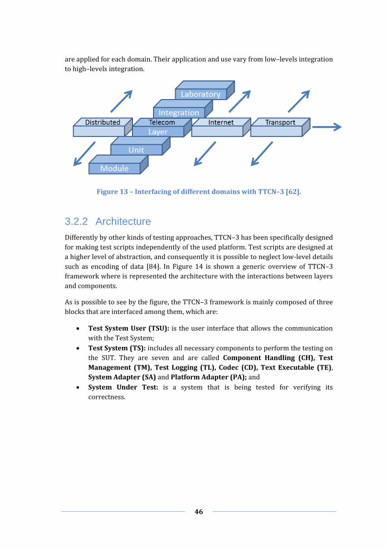
46
are applied for each domain. Their application and use vary from low–levels integration
to high–levels integration.
Figure 13 – Interfacing of different domains with TTCN–3 [62].
3.2.2 Architecture
Differently by other kinds of testing approaches, TTCN–3 has been specifically designed
for making test scripts independently of the used platform. Test scripts are designed at
a higher level of abstraction, and consequently it is possible to neglect low-level details
such as encoding of data [84]. In Figure 14 is shown a generic overview of TTCN–3
framework where is represented the architecture with the interactions between layers
and components.
As is possible to see by the figure, the TTCN–3 framework is mainly composed of three
blocks that are interfaced among them, which are:
Test System User (TSU): is the user interface that allows the communication
with the Test System;
Test System (TS): includes all necessary components to perform the testing on
the SUT. They are seven and are called Component Handling (CH), Test
Management (TM), Test Logging (TL), Codec (CD), Text Executable (TE),
System Adapter (SA) and Platform Adapter (PA); and
System Under Test: is a system that is being tested for verifying its
correctness.
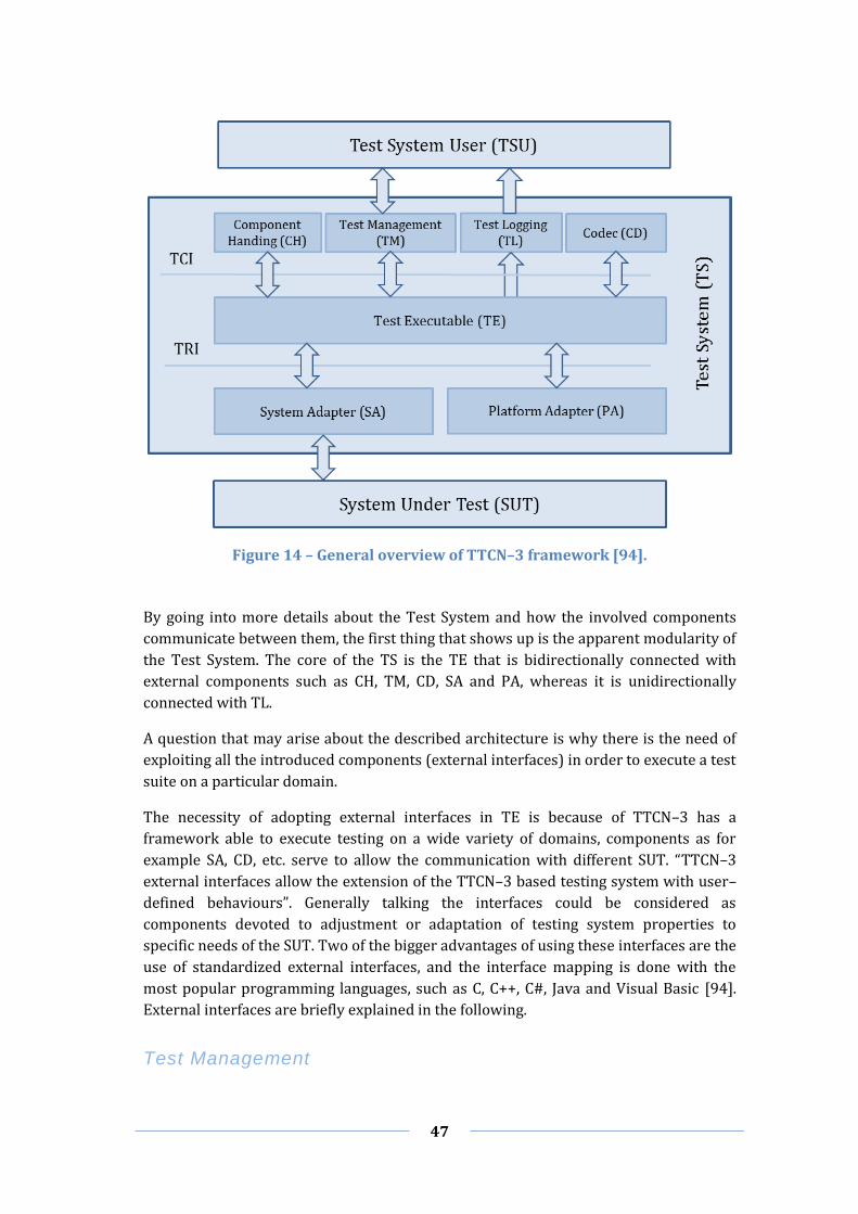
47
Figure 14 – General overview of TTCN–3 framework [94].
By going into more details about the Test System and how the involved components
communicate between them, the first thing that shows up is the apparent modularity of
the Test System. The core of the TS is the TE that is bidirectionally connected with
external components such as CH, TM, CD, SA and PA, whereas it is unidirectionally
connected with TL.
A question that may arise about the described architecture is why there is the need of
exploiting all the introduced components (external interfaces) in order to execute a test
suite on a particular domain.
The necessity of adopting external interfaces in TE is because of TTCN–3 has a
framework able to execute testing on a wide variety of domains, components as for
example SA, CD, etc. serve to allow the communication with different SUT. “TTCN–3
external interfaces allow the extension of the TTCN–3 based testing system with user–
defined behaviours”. Generally talking the interfaces could be considered as
components devoted to adjustment or adaptation of testing system properties to
specific needs of the SUT. Two of the bigger advantages of using these interfaces are the
use of standardized external interfaces, and the interface mapping is done with the
most popular programming languages, such as C, C++, C#, Java and Visual Basic [94].
External interfaces are briefly explained in the following.
Test Management

48
Test Management is responsible for overall management of the test system. It is the
only component that is able to have a bidirectional communication between the TSU
and the TS. It provides the rules (order) of execution of the various tests in the test
suite. In addition, TM provides a better support for customization of log handling and
format, and takes input to properly propagate module parameters and extra
information for testing to the TE [85] [94].
Test Logging
Test Logging is the component that takes care to collect all log messages that are
triggered during the execution of test suite. This component provides a unique
interface of input with the TE through which this latter is able to post logs. Besides, it
provides only another interface in output to allow the TSU to read message logs [85]
[94].
Component Handling
Component Handling is the component that allows the parallel distribution of test
component across one or more physical systems. Usually, the maximum efficiency of
this component is found in distributed systems where is necessary to control the
testing transparently and independently from the TE [85] [94].
Codec
Codec has the role to encode and decode messages. In particular it takes care to parse
incoming messages (byte) to establish contained field values and to construct an
abstract TTCN–3 object (abstract values) containing detected values. Vice versa, it also
executes the extraction of field values from objects to build messages. encode and
decode operations are done to allow SUT and TTCN–3 system to exchange information
with each other [85] [94].
Test Executable
Test Executable is the main and central component of the TE that deals with
interpretation and handles the execution of TTCN–3 statements. The operations of this
component depend on directives given by the main two layers [85] [94].
Platform Adapter
As mentioned above the TTCN–3 interfaces different domains, this component is
responsible to take care to set ad–hoc characteristics for the specific SUT. An example
could be the setting of timers used during the communication between ST and SUT to
understand if some message is lost or not. Since each SUT has own characteristics
about the communication, timers must be adapted correspondingly [85] [94].
System Adapter

49
System Adapter is the responsible component that allows the communication between
ST and SUT. SA is used to have a mapping between the TTCN–3’s and SUT
communication mechanisms, and the alignment of the ports for the exchange of
messages between systems, since during the TTCN–3 construction are not specified any
ports [85] [94].
Interfaces
Interfaces are intended as points of connection that allow the exchange of messages
between components. For this standard two types of interfaces are defined and they
are input and output. Moreover, the presence of one or both depends by the kind of
interfacing between components, which can be unidirectional or bidirectional.
As shown in Figure 14, a TTCN–3 framework provides two main layers in order to
allow the communication of the TE component (core) with all other components of the
TS (external components). The two layers that also define the TTCN–3 interfaces are
[94]:
TTCN–3 Control Interfaces (TCI): is the control part of TTCN–3 framework
that defines the interaction between standardized interfaces for Test
Executable, Component Handling, Test Management, Test Logging and Codec
components; and
TTCN–3 Runtime Interfaces (TRI): is the runtime part of TTCN–3 framework
that defines the interaction between standardized interfaces for Test
Executable, System Adapter and Platform Adapter. Essentially, the TRI includes
two sub–interfaces: triCommunication and triPlatform interface. The
triCommunication interface deals with communication of the Test Executable
with the SUT through the System Adapter (TE SA and SA TE), whereas the
triPlatform interface concerns to adapt with a set of operations the Test
Executable with a particular SUT through the System Adapter (TE PA and PA
TE).
In Figure 15 and Table 7 are respectively shown for the TCI the interactions between
Test System entities during the execution of the test suite, and for the TRI the
correlations between TTCN–3 operation names, TRI operation names and TRI interface
names.

50
Figure 15 – Interactions between Test System entities when executing the test suite [94].
TTCN–3 Operation Name
TRI Operation Name TRI Interface Name
execute triExecuteTestCase, triStartTimer, triEndTestCase
TriCommunication TriPlatform, TriCommunication
map triMap TriCommunication
unmap triUnmap TriCommunication
send
triSend 2
TriCommunication triSendBC 3
triSendMC 4
call triCall 2
TriCommunication triCallBC 3
2 Unicast communication.
3 Broadcast communication.
4 Multicast communication.

51
triCallMC 4
triStartTimer TriPlatform
reply
triReply 2
TriCommunication triReplyBC 3
triReplyMC 4
raise
triRaise 2
TriCommunication triRaiseBC 3
triRaiseMC 4
action triSUTactionInformal TriCommunication
start (timer) triStartTimer TriPlatform
stop (timer) triStopTimer TriPlatform
read (timer) triReadTimer TriPlatform
running (timer) triTimerRunning TriPlatform
TTCN–3 external function triExternalFunction TriPlatform
Table 7 – Correlation between TTCN–3 and TRI Operation Invocations [94].
3.2.3 Core Language
Older versions of TTCN were associated with conformance testing. However, as
described above the use of this standard has grown considerably, thus demanding to
open/expand the standard to other organizational entities, such as research centres,
companies, etc. [95]. To enable and allow the collaboration and the extension of this
language by them, the internal architecture of TTCN–3 has been refactored, and in
particular the core language. Core language is an architectural component that serves
the following main purposes [96]:
Interchange own formats with collaborative formats developed by third–parts;
Provide the semantic basis for the correct design and cooperation with
presentation formats; and
“As a generalized text–based test language in its own right” [96].

52
Figure 16 – User's view of the core language and the various formats [97].
A great feature provided by TTCN–3, that is the possibility to combine third–parts
formats with standard API’s through the interfaces TCI and TRI, remarkably facilitates
the collaboration among team members. Moreover, the coordination and distribution of
the work among team is beneficial when dealing with wide projects where many
collaborative entities are involved and countless different tasks are involved. TTCN–3
supports four kinds of formats such as Text format, Tabular format, Graphical format
and Presentation format [95]. Besides, TTCN–3 extends the support of the Presentation
format to multiple formats (Presentation Format 1, Presentation Format 2,
Presentation Format n). In Figure 16 is shown the user's view of the core language to
better clarify the structure of the TTCN–3 and interfacing with various formats. A short
explanation of the formats is provided in the following:
Textual Format: this layer represents the textual format of the Core Language
and enables testers to specify test types, data and behaviour. In Figure 17 is
shown an example of the core text format;
Tabular Presentation Format: this layer represents the information written
in the textual format, but written in a tabular format of the Core Language. This
kind of view is similar to the earlier TTCN–3 version. In Figure 18 is shown an
example of the tabular format;
Graphical Presentation Format: this layer provides a message sequence chart
based on the presentation format for UML and SDL testing profile. In Figure 19
is shown an example of the graphical format; and
Presentation Formats: these layers provide the support to other proprietary
formats.

53
Figure 17 – Example Text Format of the TTCN–3 Core Language [98].
Figure 18 – Example Tabular Format of the TTCN–3 Core Language [98].

54
Figure 19 – Example Graphical Format of the TTCN–3 Core Language [98].
3.2.4 Testing Tools
This section shows a set of TTCN–3 testing tools known to the European
Telecommunications Standards Institute (ETSI), which are available on the market and
distributed under open–source or commercial license. During the selection of these
tools a series of criteria have been taken in consideration. The most relevant criteria
are the possibility to integrate the tool with CCSimTech simulated environment, the
availability to extend the tool with plug–ins or extensions, and openness of the tool to
be customizable.
In accordance with Section 3.1.1, below are listed the selected software testing tools
related to TTCN–3 notation.
Open Source Tools
LoongTesting [99] is a TTCN–3 testing platform developed by Information
Processing Center of USTC. It includes a TTCN–3 compiler and an IDE to allow
an easy assessment of the code and creation of test suites. Moreover,
LoongTesting allows the visualization of necessary information during the
testing in order to better understand the testing result;
BroadBit Test Tool (BTT) [100] is a tool developed by BroadBit that offers the
power and efficiency of TTCN-3 notation for IT and Telecom Industry and
support to the binary and ASN.1 based definitions. BBT promises to simplify the
mapping between port definitions and port handlers (i.e. Ethernet, UDP, or Unix

55
sockets), and the generation of ASN.1 test messages or sequences of test
messages;
TRex [101] is an open source Eclipse plugin developed at the University of
Göttingen and distributed under the Eclipse Public License. It is conceived to
provide IDE functionality for the TTCN–3 core notation and support the
assessment and automatic creation of TTCN–3 test suites;
T3Tools [102] is a tool suite developed at the University of Göttingen and
provided under the terms of Eclipse Public License. It is a test tool for
automatizing code analysis in order to increase the level of confidentiality with
respect to code quality. T3Tools makes sure that coding guidelines are met.
Currently, this tool suite includes two tools that are: T3Q is a guidelines checker
for TTCN–3 specifications and T3D that is a generator of automatic
documentation for TTCN–3 test specifications. Both tools are built on a base
infrastructure provided by TRex; and
T3DevKit [103] is a toolkit distributed by IRISA and distributed under the
CeCILL–C open source license. It provides a Codec generator (t3cdgen) that
allows the automatic generation of codecs needs for coding TTCN–3 values into
physical messages. Codecs are necessary for encoding and decoding messages
that are exchanged with the SUT. T3DevLib provides a library (t3devlib) that
enables the manipulation of TTCN–3 entities (values, ports, timers, external
functions, etc.) and implementation of TRI and TCI, and provides a default
implementation of the SA, PA, TM, TL and CH. In addition, it provides build
scripts that serve for the generation of executable test suites.
Commercial Tools
Compilers and Interpreters
Exhaustif TTCN [104] is a cost–effective testing tool developed by MTP that is
used to define, implement, execute and automatize test cases based on the
TTCN–3 notation. It provides a full support to TRI and TCI, a powerful engine to
translate the TTCN–3 to C++ language and an IDE to facilitate the integration of
user–implemented code. The result of the testing is provided in HTML or XML
code. Exhaustif TTCN uses the Eclipse environment to integrate the tool with
other Eclipse and IBM Rational applications;
OpenTTCN Tester [105] is an advanced TTCN–3 tests automation tool
developed by OpenTTCN. It provides a test management GUI, TTCN–3 editor,
super–fast TTCN–3 compiler, TTCN–3 GTF Log Viewer, TTCN–3 debugger and
TTCN–3 analyser. OpenTTCN is used to build test systems based on the
following standardized languages: TTCN–3, ASN.1, XML and COBRA IDL. It
provides adapter software development kits in order to support TRI, TCI–CD
and TCI–TM in ANSI C, C++, C# and Java languages;
TestCast [106] is a test development and execution platform developed by
Elvior. It is much known and used in industrial contexts such as telecom,

56
automotive, industrial control, etc. and is one of the two tools, together with
TTworkbench, who have passed the first TTCN–3 plug–test organized by ETSI.
TestCast provides a TTCN–3 editor, compiler and executor of tests and a native
TTCN–3 debugger. With respect to the interfaces, it enables the mapping of TRI,
TCI–CD, and TCI–TM for ANSI C, C++, C#, Visual Basic and Java, and mapping of
TCI–TL for ANSI C, C++, C# and Visual Basic;
Real Time Developer Studio (RTDS) [107] is a modelling tool for real–time
and embedded software developed by Pragmadev. It supports the TTCN–3
standard testing language including syntax and semantic verification,
simulation, code generation, debug and graphical traces. Besides, it allows the
co–simulation of formal models against their related test suites and the co–
generation of generated code (design) against generated code (Unit and
Integration). RTDS offers an easy integration of the generated code with the
target, a graphical view to check the code coverage and a graphical
representation of the test verdict; and
TTworkbench [108] is an integrated test development and execution
environment developed by Testing Technologies. The relevant features of this
tool are the management, execution and analysis of TTCN–3 compiled test
suites (TTman), text–based test definition (CL Editor), compile TTCN–3
modules into executable tests (TTthree), user–friendly graphical test
specification and documentation (GFT Editor), generation of TTCN–3 scripts
out of traces (Capture and Replay Wizard), TTCN–3 source code level debugger
(TTdebug), Runtime Plugin Development Environment (RPDE).
Generators
Conformiq [109] is a tool suite developed by Conformiq, which is formerly
known as Conformiq Qtronic. It comprises Conformiq Designer that is an
Eclipse–based tool to automate the design of functional tests for software and
systems, and Conformiq Modeler that is a UML statechart editor that is used for
creating statecharts. By means of Conformiq it is possible to generate test
scripts in many different programming languages, such as C, C++, Python, Java,
Visual Basic, Perl, TCL, TTCN–3, etc. Conformiq guarantees a faster test design,
higher test quality, better test coverage, easier tester maintenance and more
test reuse;
All4Tec MaTeLo [110] is a high–end test–case designer for functional Black–
Box testing developed by All4Tec. It mainly consists of three tools that are:
Usage Model Editor, Testor and Test Campaign Analysis. The first provides a
simple GUI that allows designing test model, associate requirements, defining
test functions, calibrating test profiles and handling all needed activity to build
the model. The second is used for generating functional test cases. The last one
provides information about the campaign results. MaTeLo also provides the
validation of the Model–in–the–loop, Software–in–the–loop and Hardware–in–
the–loop. The creation of test scripts is supported with some programming
languages, such as C, C#, Python, Java, Visual Basic, Perl, TCL, TTCN–3, etc.; and

57
TestCast Generator [111] is an Eclipse plugin developed by Elvior for
automatically generating TTCN–3 test scripts. It promises to speed–up the
testing process, increase test–cycles before the software release, increase test
coverage, improve the quality of tests and allow the easy reuse of tests.
A complete comparison matrix related to features of above presented tools is shown in
Appendix B. The comparison is made on the basis of well-defined criteria such as
supported interface languages, IDE, supported protocols, supported operating systems,
minimum hardware requirements, license and price.

58
4 CCSimTech Simulated Environment
CCSimTech is a platform developed by CrossControl that enables the virtualization of
real–hardware on an ordinary PC running Microsoft Windows operating systems.
Furthermore, the collection of tools provided by this platform can also be used to
develop and test systems running Microsoft Windows virtual machines, which are able
to emulate the software environment, installed on Linux operating systems [112].
Lately, since the software area is rapidly evolving and the size of medium–large
systems is expanding has been felt the necessity to design distributed systems.
Consequently, to offset the necessity to perform testing on distributed systems, also the
testing process itself is subject to extensions and revisions in order to target those kind
of systems. In the meantime, CCSimTech can be defined as an advanced platform that
enables users to work also on distributed systems [112].
CCSimTech’s purpose is to provide a toolbox to support the development and testing of
embedded systems in simulated environments. The normal development is made by
third–party tools like Microsoft Visual Studio, which are used for coding and compiling.
CCSimTech enables the replacement of target hardware dependent operations, such as
device drivers, system calls, etc. [113]. Its main features can be summarized follows
[114]:
Simulation of CAN bus;
Simulation of IO interfaces;
Simulation of interrupts;
Simulation of memory;
Configurator of CAN bus;
Handling of time;
Interaction with LabView;
Available API’s for C, C++ and .NET; and
Set of simulation tools.
As mentioned previously in this report, the exploitation of simulated environments
carries by notable benefits as [114]:
Reduction of costs due to the virtualization of the real hardware;
Avoid the execution of tests which could result dangerous for testers;
Increase the number of dangerous tests of the virtual hardware, since there
are not risks of damage;
Quick test (re-) execution;
Use of common PCs without the need of particular development
environments; and

59
Use of many powerful debuggers that could help developers to get high
reliable software.
CCSimTech also supports HIL testing which means that some parts of the system can be
running on the real hardware. The communication used between the source
(CCSimTech) and the target is based on the CAN bus.
CAN bus is a serial bus standard designed for industrial environments. It allows the
communication among microcontrollers and devices within a network without the use
of a host computer. CAN bus is a message–based protocol designed to be used in
automotive applications, industrial automation, medical equipment, etc. [115].
In the following section is provided an overview about the basic concepts and the
architecture of CCSimTech.
4.1 Basic Concepts and Architecture
One of the main advantages of using CCSimTech is the possibility to run and test the
entire embedded system on a single PC instead of running it in many different
environments. In addition, the target software source–code can be directly executed on
the computer. This permits the exploitation of a high and reliable level of debug, and
the execution of tests in a very efficient way since for example the GUI that present on a
real device can be replicated on the simulated environment. This kind of approach has
the advantage of being deeper if compared to Black–Box hardware testing. Moreover,
for increasing the dependability of the software is possible to use external testing tools
to perform for example debugging, fault injection, etc.
Figure 20 illustrates a real system composed of four computer nodes connected by a
CAN bus, are modelled to be simulated in a PC environment. From the figure it is
possible to notice that the four I/O Nodes are represented inside the simulated
environment of CCSimTech in order to preserve the structure of the real architecture.
The CAN bus is replicated in the PC environment through the SimCAN simulation tool,
while, interfaces of I/O nodes are simulated with the SimIO simulation tool.
Furthermore, the machine model and the operator’s panel are rendered by means of
simulated models created ad–hoc for the case study. In section 4.2 additional
explanations of simulation tools is provided.
Replication of real nodes by virtual nodes and the replacement of real drivers through
virtual ones are the core features of CCSimTech.

60
Figure 20 – Simulation of computer nodes in a simulated environment [112].
In Figure 21 is shown the core concept in the simulated environment. It is mainly
composed of 3 layers that represent different levels of abstraction (software, driver,
hardware).
Figure 21 – Core concept of CCSimTech in the simulated environment [114].
Starting from the top, the Application layer contains the Embedded System Application.
As previously said, the real benefit of this kind of approach is that this is the only layer
in common between the target hardware and simulation environment. Here is
contained the source–code of the software. The Drivers layer comprises the CAN

61
connection driver, I/O interface drivers, the memory driver, etc. In the simulated
environment the Emulation Glue Layer replies it. The Hardware layer comprises the
CPU, CAN connection, I/O interfaces, EEPROM, etc., and it is replicated in the simulated
environment though the Simulation Tools layer.
4.2 Simulation Components
The layer of Simulation Tools consists of seven software components, which are [114]:
SimIO: is the component that manages the communication with peripheral
units, such as controls, motors, etc. It uses a shared memory file among nodes in
which is contained information about IO signals, such as name and value.
Moreover, it is possible to create new signals among the available four types
(digital, analogue, PWN and PULSE);
SimCAN: is the component that enables the simulation of the CAN bus. Thanks
to it is possible to connect two or more software components without the use of
external hardware. Each software component that interacts with the SimCAN
has a receive buffer that enables the reception of data sent on the bus. SimCAN
component provides several API’s that can be configured to call different
functions;
SimLIN: is the component that enables the simulation of the LIN bus. This kind
of protocol provides master–slaves communication. All nodes connected to the
bus have a send/reader buffer to exchange messages with other nodes.
Likewise to the CAN protocol, messages sent from the master are stored in all
slaves buffer. In addition, it uses a shared memory file accessible from all nodes;
SimSerial: is the component that enables the point–to–point communication
between two nodes (RS232 connection). It is often used in embedded systems
to configure and read log of nodes in the system with a separate device (node).
Besides, SimSerial has two buffers for allowing the exchange of messages; one is
used for the reading and other one for the writing;
SimMemory: is the component that enables the simulation of EEPROM and
flash memories. It creates a shared dynamic load library file that contains
information such as name, size, block size and type. The information is
accessible through the tool MemoryTool, which is presented below;
SimInterrupt: is the component that provides the registration of call–back
functions in an application. Moreover, it allows registering specific event
triggers; and
SimScript: is the component that allows the automatic execution of scripts for
performing automatic tests.
Simulation tools, which are part of the CCSimTech toolbox, manage the software
components listed above. In the following section they are briefly presented.

62
4.3 Simulation Tools
The CCSimTech toolbox consists of the following tools: BusTool, IoTool, MemoryTool,
SimCAN Configurator, SimIo2Eth Server and SimScript.
BusTool
BusTool is the application that allows the manual sending and logging of messages on
the bus. It provides the feature to log messages exchanged on the bus, which could be
helpful during the development process, and in particular when testing and monitoring
of the software is executed. Moreover, BusTool allows the personalization of the
visualization of certain kind of messages to permit for performing a more in depth
check of the SUT. [114] [116].
IoTool
IoTool is the application that enables view and control of IO signals that are active on
the component SimIO. It shows by default the port name of signals and the value
associated to each signal. Moreover, this application allows the override of signal values
in real–time. Other features provided by IoTool are the visualization of the value in
different notations such as binary and hexadecimal, the visualization of the min and
max value that signals assumed, and the history of signals when the system is operating
[114] [116].
MemoryTool
MemoryTool is the application that enables view and control of memory files used
during the simulation. It provides the feature to override a memory segment value of a
certain memory file and the possibility to execute jump to a given memory address or
block, or the erasing of a given memory or memory block. Besides, some information
about the opened memory files can be shown, such as name, type, size, block count,
block size, etc. [114].
SimCAN Configurator
SimCAN Configurator is the application that enables the configuration of the CAN bus
(SimCAN simulation component). It shows the status of the CAN adapter installed on
the PC and allows the configuration of different connection profiles. The
personalization of profiles provides the configuration of the CAN net, interface, mode,
device name, call–back, timeout, remote transmission request, etc. Furthermore,
configurations can be saved in XML files [114].
SimIo2Eth Server
SimIo2Eth Server is the application that enables clients to connect and extend the
simulated I/O to another computer or another emulated computer over Ethernet

63
connection. It is commonly used for the integration of virtual machines in the
simulation. SimIo2Eth allows the connection of up to ten clients at the same time. The
main feature provided by SimIo2Eth Server is the possibility to set the connection port
[114].
SimScript
SimScript is the application that enables the automatic execution of scripts. Scripts are
files in which there are written instructions to set and send messages on the CAN bus. It
provides some features such as the possibility to take in input CAN files, which contain
instructions and messages to send on the bus. Moreover, SimScript allows to store log
in files or to display it on console, and can parse input files without executing them.

64
5 Survey of CrossControl and
Customers’ Environments, Limits and
Needs
This section is the result of some interviews made to CrossControl, Bombardier
Transportation and Volvo Construction Equipment’s employees. CrossControl is a
Swedish company whose purpose is to support manufacturers of industrial vehicles
with solutions that deal with humans in control of vehicles working in critical
environments. Bombardier Transportation is one of the world’s largest companies in
rail–equipment manufacturing and servicing industries with a wide product range of
passenger trains, locomotives and bogies. Moreover, they provide software for their
vehicle control systems with several ECUs. Volvo Construction Equipment is one of the
largest manufacturers of vehicle construction in the world with a wide product range of
loaders, excavators, haulers, motor graders, milling equipment, pipelayers, demolition
equipment, waste handlers, pavers, compactors and skid steers.
These interviews mainly served to provide information to CrossControl regarding their
testing types. Information collected was about the development and testing
environments, limits and needs that employees use/have during the realization phase
of a software. This survey allowed us to collect useful information in order to make a an
appropriate analysis of existing testing systems. Furthermore, it served as a precious
input to CrossControl with the purpose to understand future developments and what
could be new techniques and methods to adopt with the aim to improve and increase
testing tools capabilities.
Interviews covered development environments, programming languages, testing tools,
testing methods, testing notations, protocols used, etc. The most popular questions that
have been provided during these interviews were as follows:
What types of software testing are you using?
Are you using Black–Box or White–Box testing techniques?
During the development process, are you using Unit, Integration and System
testing methods?
What kinds of methods are you using?
What tools are you using for the execution of Unit, Integration and System
testing?
What are the pros and cons of each tool?
Do you have some limitations in using these tools?
Do you need more than one tool of the same testing method to obtain the
expected result?
What are these limitations that force you to use alternative tools for getting a
good testing?

65
Are you running manual or automatic tests?
What is your opinion about the automation of the tests execution?
Do you think that the testing automation could be a way to save money and
time?
Do you use Hardware-In-the-Loop testing?
What tools are you using for the HIL testing?
What limitations are you having during the utilization of them?
During the testing, are you using Fault Injection techniques?
What kinds of techniques are you using?
What tools are you using for the Fault Injection testing?
Are you having some limitations during the fault injection?
What are the greatest efforts that you have in terms of costs and time during
the testing?
What kinds of existing test notations do you know?
The relevant information carried out from these interviews is illustrated in the
following sections. In particular, we classify feedbacks in three different categories:
testing environments, limits, and needs.
The theoretical discussion given so far worked as the necessary background in order to
comprehend and interpret practices, issues, and needs arising from these interviews.
After the collection of customers' information and their synthesis, we implement a
testing solution in a simulated environment in order to evaluate it against customers'
needs.
5.1 Development and Testing Environments
Operating system environments used by the companies mentioned above are mainly
based on Microsoft Windows platforms, in detail on the XP version and higher, and on
open source platforms such as Linux/Unix.
Testing tools generally used are manual solutions that may or not provide a GUI. Often,
tools that do not provide a GUI are used to perform White–Box testing, such as xUnit,
GNU–compilers, etc.; whereas tools that provide a GUI are used to perform Black–Box
testing such as TestComplete used by CrossControl, SE–tool and LabView used by
Volvo, Test Script Editor (TSE) and Text Executor Manager (TEM) used by Bombardier
Transportation, etc. Lately, Bombardier is also working on the automation of testing
processes in order to speed up this phase. The involved tools by TSE, which is used for
creating test cases, and TME, which is used for executing test scripts created with TSE.
Besides, with respect to testing notations adopted by these companies, the XML
notation is the most popular in current projects.

66
Most of the projects provide a high–level testing that is an object–oriented testing
approach; whereas, only a little part of projects provides a low–level testing that means
for programmers or testers to have a source–code testing approach (interaction with
CPU, Memories, Disk, etc.). The technique used during development processes is mostly
Black–Box testing, whereas White–Box is only exploited for particular situations. The
general testing technique used for debugging complex real–time embedded systems is
the HIL. The most widely exploited technique for debugging the software is the System
testing, whereas rarely Unit testing, Integration testing and Fault Injection testing are
used. Besides, the general software development process adopted by companies is the
V–Model because of its simplicity and ability in simplifying the understanding of the
system developing complexity.
Mostly used programming languages are C, C++ and C#. C is used in projects where a
low–level coding is requested, whereas C++ and C# are used where a high–level coding
is needed (i.e. when the use of object–oriented programming languages is necessary).
Finally, since the mentioned companies work in areas related to the vehicle
development, the communication protocol mostly known and used is the CAN bus.
5.2 Development and Testing Limits
This section illustrates the main limits in system development and testing as faced by
CrossControl, Bombardier Transportation and Volvo Construction Equipment. Major
difficulties in these activities are:
Difficulty in maintaining the traceability between source–code and test cases
because most of the development processes do not provide a test–driven
approach. This means that when are applied some evolutions in the source–
code the traceability between source–code and test cases becomes very tricky
to keep. Usually problems grow with the size and complexity of the project;
Difficulty in finding open bugs when discovered since most of the testing is
done Black–Box. This issue mainly occurs when they are not due to the portion
of the SUT, but they got propagated function-by-function. Often the operation to
fix bugs in this condition takes a long time;
Difficulty in managing exceptions because of a lack of dedicated testing support.
As for the previous limitation, this issue arises from the absence of Unit testing;
Difficulty in testing the entire system due to the lack of System testing, indeed
the complete result of the entire system is done by the collection of n sub–
systems results;
Difficulty in speeding up the testing process because most of the testing phase
is done manually. Since it requires remarkable effort and time to companies,
they sometimes tend to decrease testing budgets causing potentially poor
quality of products. In particular, it is interesting to notice that when these
situations occur regression testing is very often the first one to be reduced; and

67
Difficulty in carrying out tests on real targets due to high costs, dangerousness
of critical environments, etc. This limitation arises from the lack of simulated
environments that allow the execution of any type of test.
5.3 Development and Testing Needs
This section presents some important needs of CrossControl, Bombardier
Transportation, Volvo Construction Equipment and their employees. The common need
that all companies have expressed is the replacement of the current manual testing
approach with an innovative solution that offers an automatic execution of test cases.
Furthermore, increasing the number of test cases with the purpose to improve the
software quality assurance is a common wish. Accordingly increasing test cases and
achieving their automated execution, discloses the additional opportunity of running
test suites during the night with the aim to have a daily feedback. Moreover, the
approach of making daily builds and nightly tests contribute to speed up software
realization due to a quick and continuous integration among different development
parts. To summarize, there is the need for enhanced nightly test executions and daily
integrations between different software components, which is typically referred to as
“Continuous Integration testing”.
One of the most common goals pursued by development processes is saving time of
system development devoted to test suite execution. The underlying objective is
quickly increasing the system reliability by means of frequent test execution. In any
case, test suite execution rate is a trade-off between time spent writing code and
testing. Balancing these two activities is not easy and represents an open issue for the
companies taken into account.
The use of regression testing is nowadays becoming a very important need during
system development process, because due to the adoption of new development
methods and a system is incrementally refined thus disclosing versioning support
needs. In this respect, regression testing is a useful method that provides rerunning of
previously run tests and checking whether the system behaviour has changed or if
previously fixed faults have recurred.
Usually, during the development of medium–large systems many testers and testing
tools are involved. The use of different testing tools could sometimes create problems
related to the porting of test cases among them since they are based on different testing
notations and scripting languages. As a consequence, another problem raised by these
companies is the need to minimize the effort to port test cases among testing tools, for
example by standardizing testing notations or providing new features to import them.
The replacement of real target platforms with simulated ones is becoming more and
more interesting; indeed, the request of these companies to adopt simulated
environments is significantly increasing for the purpose to save money and takes
advantage of the benefits already mentioned several times in this report.

68
Finally, since these companies are using the CAN bus protocol, improving the reliability
and robustness of the protocol management using specific testing methods like the
Fault Injection testing is highly desired.

69
6 CrossControl’s Case Study: Design,
Implementation and Testing of a
Demonstrator Project
In the previous section we discussed common primary industrial needs as collected in
the selected companies. One of those needs is to perform tests on simulated
environments in order to gain reproducibility of tests, decrease the costs of operating
on the real hardware and potentially harming humans' lives.
This chapter provides a demo (or proof-of-concept) of how could be possible to replace
in future the testing done on a real environment though a simulated environment. The
main idea is to start from the architecture of a real environment and by means of a
careful analysis to understand what parts is possible to simulate. For architecture parts
are intended hardware components, communication systems and communication
interfaces.
Since the purpose of CrossControl is to provide technology that puts humans in control
of vehicles in critical environments, the case study provided in this chapter is based on
a tractor. In Figure 22 is shown the architecture of the tractor with depicted all parts of
the real environment, which are interested by the simulation. They are the On–Board
Computer, Controller, Display, IO Device and Vehicle. In addition, the CAN bus and
IO signals communication have been selected.
Figure 22 – Representation of the real environment.

70
In Figure 22 are displayed real parts of the vehicle that are replaced with simulators in
the following step. Moreover, as it is possible to notice, different vehicle abstractions
have been considered during the selection. Starting from the left to the right, the first
picture represents the On–Board Computer that usually is located inside the cabin and
is considered the head of the vehicle. The second picture shows the Display and
Controller that are located inside the cabin as well and provide necessary instruments
to communicate with the vehicle. The third picture illustrates the IO signals, which are
sensors/actuators located in the vehicle such as fuel level, water temperature, lights,
etc. and the IO Device that enables the communication among sensors/actuators and
On–Board Computer.
As expected, the simulated environment is meant to mirror the real environment,
component-by-component, as depicted, as in Figure 23.
Figure 23 – Representation of the simulated environment.
By comparing Figure 22 and Figure 23 it is easy to notice the similarity between their
architectures. In particular, all parts pertaining to the real environment have been
replaced with simulators. The communication among On–Board Computer, Display,
Controller and IO Device has been replaced with the SimCAN, whereas the
communication between the IO Device and Vehicle is SimIO. Moreover, another level of
simulation is demanded for the driver component. The driver is the software
component related to the simulator that allows the exchanging of information with
other simulators located on the same bus. In fact, for each component a corresponding
interface has been realized, with the only exception of the Display and Controller that
have a unique interface. The drivers developed for the demo, even if presenting
approximately the same structure about the communication part, are developed in
different languages (Visual C++ and Visual C#).

71
The implementation of the SUT is briefly presented in the following section, by
providing information about the used IDE, programming languages, etc. Subsequently,
details are provided about all simulators with their relative functionalities. Finally, the
chapter is completed with a deep explanation of the testing phase applied on this demo.
In particular, it is discussed how it is possible to execute testing on the SUT in the
simulated environment byusing different methods and techniques, such as Black–Box
and White–Box testing methods, and Unit, Integration and System testing
techniques.
6.1 Implementation
In accordance with the System Development Model introduced in Section 2.2, the
implementation phase comes after the requirement analysis, system design,
architecture design and model design.
Since the main goal of this report is to discuss software testing methods in simulated
environments, the other phases of the development process are not taken into account.
In Appendix E is shown a list of SUT functional requirements that will be referred to in
the remainder of this section. This list is necessary to validate if the behaviour of the
SUT satisfies the requirements. Usually, the main testing phase that takes care to
validate the software is called “Acceptance Testing”.
By taking into consideration the architecture depicted in Figure 23, the SUT consists of
a set of simulators, interfaces and means of communication. Its physical architecture
results to be not so complex, but vice versa the software architecture is a little bit
trickier because the implementation involves different programming languages,
communication interfaces and communication means, like CAN bus and IO signals.
The implementation has been driven with the intention to reuse this demo as a basis
for future works. In particular, the choice of the simulator languages has been done
depending on the simulated hardware; moreover, simulators and own communication
interface languages have been kept the same interfaces have been made modular in
order to add and remove system features, such as break, lights, etc.; finally, similar
communication interface structures have been realized both across simulators and
between different languages in order to ease system maintenance.
Generally, each communication interface based on CAN bus is provided with a function
set to manage the communication. Main functions are openCanCom, receiveMsg,
sendMsg, and checkMsg. openCanCom takes care to open the CAN communication
specifying also the channel name. receiveMsg takes care to read the message in the
receive buffer, call the function checkMsg and delete the message from the buffer.
checkMsg is the function that takes care to analyse all messages present on the bus in
order to verify the correctness of messages. In detail the function is responsible to
check if the message ID is recognized and if the data content is acceptable. For
applications developed in Visual C++, if a message is not correct is thrown an exception

72
message, whereas if it is correct is called the appropriate function to received message.
Instead, for applications developed in Visual C#, if a message is not correct is shown a
GUI exception message; otherwise the opposite function to the received message is
called.
Since the On–Board Computer and IO Device simulators are two applications that do
not need a GUI they are developed in Visual C++, whereas the Display, Controller and
Vehicle simulators are developed in Visual C#. The decision to adopt these kinds of
languages comes out from a careful consideration and evaluation of a series of factors,
such as performance, ease of portability of the source–code in a real environment,
system component purpose and integration with some libraries provided by Cross
Control.
In the following sections are presented the five simulators that make up the system.
On–Board Computer Simulator
On–Board Computer Simulator is the main component of the simulated environment
because it takes care to manage all information related to the vehicle. Information
managed from this simulator includes the status of vehicle components, such as key,
engine, hand brake, brake, Power Take–Off (PTO), All Wheel Drive (AWD), Arrow Sx
(left indicator), Arrow Dx (right indicator), Hazard Lights, low and high Lights, Throttle,
read and forward Gear, set of Screen, Water Temperature, Fuel Level, Revolutions Per
Minutes (RPM), Kilometres per Hour (KMH), Hours of work of the vehicle, Warnings,
Battery Level, Battery Warning, Fan Warning and synchronization of all warnings.
The primary aim of this simulator is to analyse information sent on the CAN bus, and
act accordingly in updating the status of vehicle components and respond to requests.
For example, if the On–Board Computer can receive a message to change the status of
the Key component, either to turn–on or to turn–off the Key (system), to which it reacts
by calling the corresponding function. During the execution of these functions the
current status of the component is written on the Win32 Console; moreover, since a
real On–Board Computer is considered a Black–Box system, these updates are stored in
a log file. Besides, since the On–Board Computer is connected via CAN bus to the other
simulators, it provides some internal functions necessary to open the CAN bus
communication and send/receive messages.
In Figure 24 the Win32 Console application of the On Board Computer Simulator is
shown during its execution.

73
Figure 24 – On–Board Computer Simulator.
As illustrated in the screenshot, in the console are displayed messages related to the
operation of the simulator. Prevalently, messages written on the console are of two
types: INFO and ERROR. The former represents the category of messages during a
regular execution, such as system changes, warnings, etc., instead, the latter identifies
messages related to system errors due to an irregular execution, such as the
impossibility to operate on the CAN bus or the reception of unrecognized messages
(wrong ID or data). Values shown in console at the end of messages represent new
component status in case of INFO messages, whereas, error numbers in case of ERROR
messages.
Display Simulator
Display Simulator is the component that takes care to simulate the display located
inside the vehicle cabin. Its functionality is to show to the driver information regarding
the vehicle and it consists of two parts. The top part constitutes the screen where are
shown information about water temperature, gear, RPM, KMH, Hours, current Date and
fuel level. In addition, during the system start–up its loading status is shown on the
screen. Instead, the bottom part consists of a set of indicator lights to signal the driver
the status of certain vehicle components, such as PTO, AWD, Arrow Sx, Hazard Lights,
Arrow Dx, Warnings, Battery Warning, Fan Warning, Brake, Hand Brake, low and high
Lights.
The Display Simulator is shown Figure 25.

74
Figure 25 – Display Simulator.
Having in mind that simulators shall be able to work independently from each other,
information shown on the display through indicator lights and screen are received from
the On–Board Computer. As can be seen in Figure 23, even though the Display and
Controller share the same communication interface though the CAN bus, no
information is directly exchanged between them. All communications between them
are done via bus.
The choice to develop independent simulators has brought some advantages, such as
the ability to have a modular system that allows the insertion and removal of other
simulators. Moreover, thanks to the system modularity and flexibility it is also possible
to make a hybrid system, which consists of simulated and real hardware components
mixtures. A simple example of hybrid system could be the execution of the Display
Simulator in a real environment. This advantage is very important during the
development because it permits to test the system in different conditions and levels of
integration.
Controller Simulator
Controller Simulator is the component of the simulated environment that allows the
driver to manage the vehicle executing some actions, such as turn–on and turn–off the
system, Engine, Hand Brake, Brake, PTO, AWD, Arrow Sx, Hazard Lights and Arrow Dx,
and switch the Lights, Throttle and Gear.

75
Figure 26 – Controller Simulator.
In Figure 26 is depicted the Controller Simulator. As shown by the picture, the
simulator consists of some buttons and switches that simulate physical parts of the
vehicle. Each button can assume status ON or OFF. Furthermore, for the status ON can
be “active” or “inactive”. This variety of states is encoded as follows: when the label of
the button is white it means that the button status is OFF; when the label turns to green
the button in ON but still not active; when the button itself turns to green and its label
to black, then it became ON and active. For the switch of lights, when the selector is
positioned on OFF it means that the lights are OFF, when it is positioned on Low then
low lights are active and when it is positioned on High means that high lights are active.
For the throttle when the selector is positioned on Min means that it is inactive,
whereas when it is positioned on other positions means that it is active with associated
the related value. For the gear, when the selector is positioned on N it means that it is
inactive, whereas as for the throttle, when the selector is positioned on other positions
then it is active with associated the related value.
IO Device Simulator
IO Device Simulator is the component of the simulated environment that allows the
conversion of CAN messages in Input/Output signals and vice versa. It is a Win32
console application and as can be noticed in Figure 27 it reflects the On–Board

76
Computer application in displaying messages. In fact, similarly to the On–Board
Computer it displays INFO and ERROR messages in the same way.
Differently to other simulators, IO Device is the only one that presents two interfaces of
communication, one for enabling the communication on the CAN bus, and the other to
enable the get and set of Input/Output signals.
Figure 27 – Input/Output Device Simulator.
Information managed from this simulator is about the status of vehicle components,
such as Key, Engine, Hand Brake, Brake, PTO, AWD, Arrow Sx, Arrow Dx, Hazard Lights,
low and high Lights, Throttle, read and forward Gear, Water Temperature, Fuel Level,
RPM, KMH, number of Hours of the vehicle use, Battery Level and Fan set. The values at
the end of messages represent new statuses of the vehicle component.
Vehicle Simulator
Vehicle Simulator is the component of the simulated environment in which is depicted
the vehicle under test with some icons that represent sensors and actuators of the
vehicle, such as Engine, Hand Brake, Lights, etc. Moreover, this simulator offers the
possibility to manually set the Fuel Level, Fan operation and Battery Level.
In order to make this simulator as close as possible to the real environment, its
implementation provides mechanisms to simulate the progress of increasing and
decreasing of RPM, KMH, Fuel Level, Water Temperature and Battery Level. RPM value
is calculated with a function that considers the current position and shifting of the
Throttle and Gear. KMH value is calculated in accordance with the RPM value and
engaged Gear. Moreover, RPM and KMH functions are implemented to have a
continuous like behaviour, as in a real situation. Fuel Level value is calculated on the
basis of RPM; in fact, if the value of RPM is high the Fuel outflow is greater, whereas if

77
the value of RPM is low the Fuel outflow is less. The Water Temperature varies on the
basis of the RPM value and Fan operation. When the Fan is OFF the temperature
increases quickly or slowly in agreement with the RPM value, whereas if the Fan is ON
the temperature decreases quickly or slowly in agreement with the RPM value. Finally,
the Battery Level increases or decreases in agreement with the Engine operation. If this
last is ON the Battery Level increases, vice versa, if the Engine is OFF the Battery Level
decreases quickly or slowly in agreement with active system parts (Lights, Arrow
lights, Brake lights, Display, Controller lights, etc.).
Figure 28 depicts the Vehicle Simulator during its execution. Icons that have a grey
colour are inactive, whereas icons in different colours are active. Yellow icons located
in front of the vehicle represent low Lights and those located on the cabin represent the
high Lights. Orange icons represent the Arrow Sx, Arrow Dx and Hazard Lights. Green
icons represent the Fan, Engine and PTO. Red icons located on back wheels show that
the system is active (Key inserted), whereas red icons located on front wheels
represent the AWD. Besides, the two track bars shown under the vehicle represent its
speed.

78
Figure 28 – Vehicle Simulator.

79
6.2 Testing
This section presents an important stage in the development of the demonstrator that
takes care to verify its correctness. In this case study, it has been considered as more
appropriate to perform testing after the implementation rather than adopting a test-
driven approach. The first part of this section includes the selected testing tool used for
executing White–Box and Black–Box techniques according to some of the previously
explained testing methods, like Unit, Integration and System testing.
The evaluation for the tool selection has been made among many software testing tools
available on the market, as described in Sections 3.1.1 and 3.2.4. It has been made in
three different phases; the first one is mainly based on the market popularity and their
distribution type that is freeware (primarily open–source) or commercial. The second
phase involved CrossControl and customers’ information, limits and needs described in
Chapter 5. From the second evaluation round is turned out that the most suitable tools
to be adopted by CrossControl for future implementations are C++Test, dotTest, QA
Wizard Pro, Ranorex, TestComplete and TPT about general notations, while,
OpenTTCN, TestCast and TTworkbench for the TTCN–3 notation. Eventually, the third
selection phase took into account SUT characteristics and features. During this last
phase a difficult and careful analysis has been made among the author and
CrossControl’s supervisor and employees in order to first of all select the notation to
adopt that is general or TTCN-3, and then a suitable tool supporting the chosen
notation. After such long evaluation process, TestComplete resulted as the most
suitable solution to perform testing on the current SUT.
In the following sections are shown portions of testing results performed on the entire
system and a few test cases, without entering into too many details on these latter. In
particular, for demonstrating the execution of White–Box testing using the Unit testing
method, the Display and Controller simulators have been selected. For illustrating
Black–Box testing technique using the Integration testing method has been selected the
subsystem composed by Display, Controller and On–Board Computer simulators;
instead, for describing Black–Box testing by using the System testing, all implemented
simulators of the SUT have been tested. Furthermore, since these simulators are
connected to each other via CAN bus or IO connection, performing these tests on the
system brings the important advantage of also verifying the correctness of the
communication among them.
In order to perform the testing on the SUT, an adaptation has been necessary for
interfacing the source code of the simulators with test cases. In particular, this step
involved the creation of appropriate extra methods enabling the interplay between
simulators and test cases created by TestComplete. The creation of these methods has
been essential since some methods of the source code are marked “private” therefore
they cannot be accessed from methods declared in other files. A few examples of these
extra methods are GetLabelGear, GetPictureBrakeOn, GetPictureBrakeOff,
GetProgressLoad and GetPanelScreenLoad for the Display Simulator, and

80
GetStatusButtonKey and ButtonKeyClick for the Controller Simulator. They are
respectively defined as follows.
EXTRA METHODS OF THE DISPLAY SIMULATOR
public String GetLabelGear() { String text = ""; this.UIThread(delegate { text = labelGear.Text; }); return text; } public Boolean GetPictureBrakeOn() { Boolean value = true; this.UIThread(delegate { value = pictureBrakeOn.Visible; }); return value; } public Boolean GetPictureBrakeOff() { Boolean value = true; this.UIThread(delegate { value = pictureBrakeOff.Visible; }); return value; } public Byte GetProgressLoad() { Byte value = Definitions.OFF; this.UIThread(delegate { value = (Byte)progressLoad.Value; }); return value; } public Boolean GetPanelScreenLoad() { Boolean value = false; this.UIThread(delegate { value = panelScreenLoad.Visible; }); return value; }

81
EXTRA METHODS OF THE CONTROLLER SIMULATOR
public Button GetStatusButtonKey() { Button button = null; this.UIThread(delegate { button.BackColor = buttonEngine.BackColor; button.ForeColor = buttonEngine.ForeColor; }); return button; } public void ButtonKeyClick() { buttonKey.PerformClick(); }
By taking a closer look to these methods it is noticeable the recurring exploitation of a
type called “delegate”. This type references a method and can be used to encapsulate a
named or an anonymous method. In addition, as is possible to see below in “Methods to
check test results”, some methods have been created to verify the validity of
implemented test cases by taking care to return test results, which are
NotEqualsErrorMessage, EqualsErrorMessage, CheckEquals and CheckNotEquals.
Differently from the previous methods these latter ones return String messages or
throw exceptions. Moreover, while the previous methods do not take any parameter in
input, these ones take three parameters to evaluate the test and return its verdict.
These parameters are expected value, actual value and message. The last parameter
contains the message to display in case of test failure. In particular, they execute
evaluations by comparing expected and actual value represented as String parameters.
Similar methods (not shown in the Table) have been implemented to support other
data types, such as Byte, Boolean, CAN messages, Color and Long. Below an excerpt of
the methods discussed so far is shown.
METHODS TO CHECK TEST RESULTS
#region to control test results (String) private String NotEqualsErrorMessage(String Expected, String Actual, ref String Msg) { if (Msg != "") Msg = Msg + " : expected " + Expected + ", but was: " + Actual; return Msg; } private String EqualsErrorMessage(String Expected, String Actual, ref String Msg) { if (Msg != "") Msg = Msg + " : expected " + Expected + " and actual were: " + Actual; return Msg; } private void CheckEquals(String Expected, String Actual, String Msg)

82
{ if (Expected != Actual) { NotEqualsErrorMessage(Expected, Actual, ref Msg); Exception exception = new Exception(Msg); throw exception; } } private void CheckNotEquals(String Expected, String Actual, String Msg) { if (Expected == Actual) { NotEqualsErrorMessage(Expected, Actual, ref Msg); Exception exception = new Exception(Msg); throw exception; } } # endregion
In the following sections are discussed the details regarding the application of the Unit,
Integration and System testing to this case study.
Unit Testing
This section describes all methods that have been tested of the Display and Controller
simulators and their results.
The following code depicts designed cases to test the correctness of Display Simulator
methods. In this table, as for the Controller Simulator, only some test cases are
reported, such as TestLabelGear_1, TestLabelGear_4, TestChangePictureBrake_1,
TestChangePictureBrake_3, TestProcessLoad_1, TestProcessLoad_3,
TestSwitchScreen_1 and TestSwitchScreen_4. Moreover, for each type of test two
versions are provided, one valid and one invalid. The valid version provides an input
and a correct expected result, whereas the invalid provides an input and a wrong result.
TEST CASES OF DISPLAY SIMULATOR
#region Label Gear // valid public void TestLabelGear_1() { FormDisplay display = new FormDisplay(); Byte[] gear = { 0x00, 0x00 }; display.ChangeLabelGear(gear); CheckEquals("N", display.GetLabelGear(), "The Gear field has not been properly set"); } // invalid public void TestLabelGear_4() { FormDisplay display = new FormDisplay();
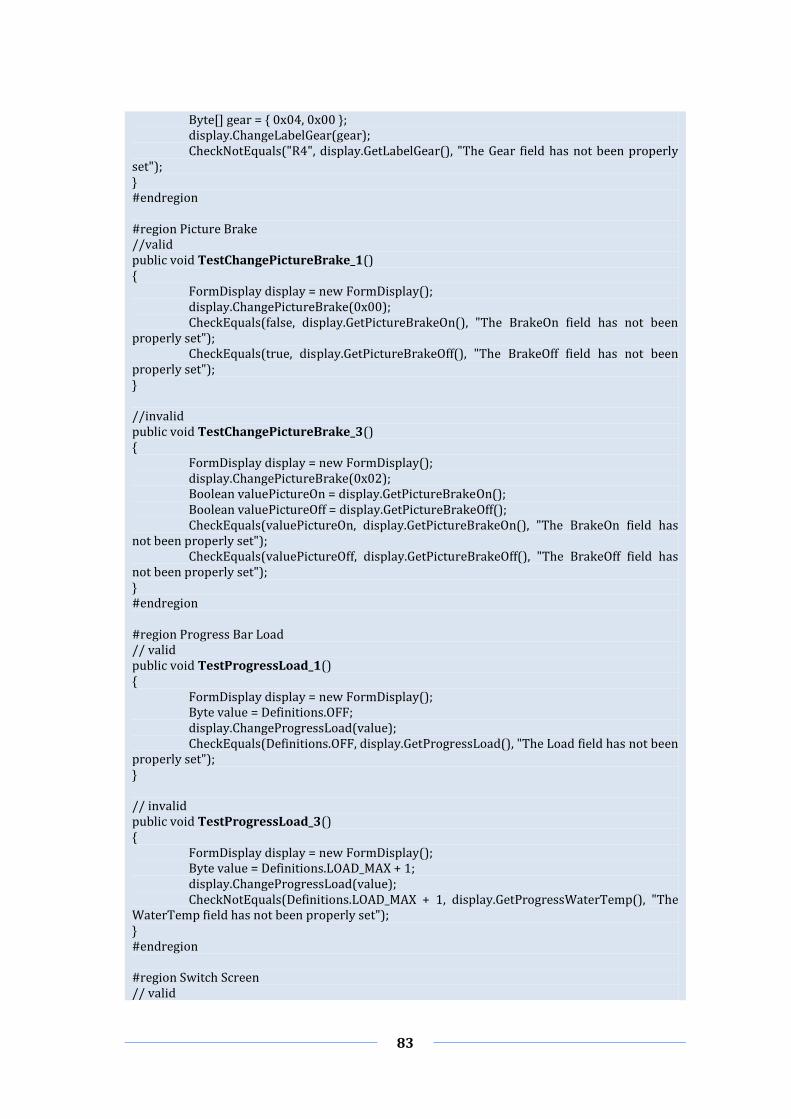
83
Byte[] gear = { 0x04, 0x00 }; display.ChangeLabelGear(gear); CheckNotEquals("R4", display.GetLabelGear(), "The Gear field has not been properly set"); } #endregion #region Picture Brake //valid public void TestChangePictureBrake_1() { FormDisplay display = new FormDisplay(); display.ChangePictureBrake(0x00); CheckEquals(false, display.GetPictureBrakeOn(), "The BrakeOn field has not been properly set"); CheckEquals(true, display.GetPictureBrakeOff(), "The BrakeOff field has not been properly set"); } //invalid public void TestChangePictureBrake_3() { FormDisplay display = new FormDisplay(); display.ChangePictureBrake(0x02); Boolean valuePictureOn = display.GetPictureBrakeOn(); Boolean valuePictureOff = display.GetPictureBrakeOff(); CheckEquals(valuePictureOn, display.GetPictureBrakeOn(), "The BrakeOn field has not been properly set"); CheckEquals(valuePictureOff, display.GetPictureBrakeOff(), "The BrakeOff field has not been properly set"); } #endregion #region Progress Bar Load // valid public void TestProgressLoad_1() { FormDisplay display = new FormDisplay(); Byte value = Definitions.OFF; display.ChangeProgressLoad(value); CheckEquals(Definitions.OFF, display.GetProgressLoad(), "The Load field has not been properly set"); } // invalid public void TestProgressLoad_3() { FormDisplay display = new FormDisplay(); Byte value = Definitions.LOAD_MAX + 1; display.ChangeProgressLoad(value); CheckNotEquals(Definitions.LOAD_MAX + 1, display.GetProgressWaterTemp(), "The WaterTemp field has not been properly set"); } #endregion #region Switch Screen // valid

84
public void TestSwitchScreen_1() { FormDisplay display = new FormDisplay(); Byte[] value = { 0x00, 0x00 }; display.SwitchScreen(value); CheckEquals(true, display.GetPanelScreenOff(), "The ScreenOff field has not been properly set"); CheckEquals(false, display.GetPanelScreenLoad(), "The ScreenLoad field has not been properly set"); CheckEquals(false, display.GetPanelScreenInfo(), "The ScreenInfo field has not been properly set"); } // invalid public void TestSwitchScreen_4() { FormDisplay display = new FormDisplay(); Byte[] value = { 0x01, 0x01 }; display.SwitchScreen(value); Boolean panelScreenOff = display.GetPanelScreenOff(); Boolean panelScreenLoad = display.GetPanelScreenLoad(); Boolean panelScreenInfo = display.GetPanelScreenInfo(); CheckEquals(panelScreenOff, display.GetPanelScreenOff(), "The ScreenOff field has not been properly set"); CheckEquals(panelScreenLoad, display.GetPanelScreenLoad(), "The ScreenLoad field has not been properly set"); CheckEquals(panelScreenInfo, display.GetPanelScreenInfo(), "The ScreenInfo field has not been properly set"); } #endregion
In Table 8 are listed the results of test cases performed on the Display Simulator. On the
first, second and third columns are reported test case codes, test case names and test
case results after the first execution; whereas, the last column contains a mapping of
the test case with the corresponding requirement (in terms of a code) the test is meant
for to verify. The functional requirement codes serve to match test cases with
functional requirements of the demonstrator to keep the traceability between them.
Furthermore, the traceability is useful to measure the coverage of the test suite with
respect to the SUT.
It is worth noting that some functional requirements may not appear in the following
tables. In fact, since simulators communicate with each other through the exchange of
CAN messages or IO signals, some functional requirements are present in all test cases
and hence omitted. They are from FR001 to FR006 for the On–Board Computer
Simulator, from FR101 to FR106 for the Display Simulator, from FR201 to FR206 for
the Controller Simulator, from FR301 to FR306 for the IO Device Simulator and from
FR428 to FR432 for the Vehicle Simulator. An entire list of functional requirements is
depicted in Appendix E.
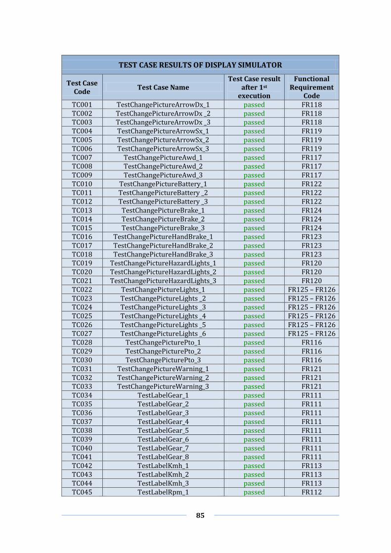
85
TEST CASE RESULTS OF DISPLAY SIMULATOR
Test Case Code
Test Case Name Test Case result
after 1st execution
Functional Requirement
Code TC001 TestChangePictureArrowDx_1 passed FR118 TC002 TestChangePictureArrowDx _2 passed FR118 TC003 TestChangePictureArrowDx _3 passed FR118 TC004 TestChangePictureArrowSx_1 passed FR119 TC005 TestChangePictureArrowSx_2 passed FR119 TC006 TestChangePictureArrowSx_3 passed FR119 TC007 TestChangePictureAwd_1 passed FR117 TC008 TestChangePictureAwd_2 passed FR117 TC009 TestChangePictureAwd_3 passed FR117 TC010 TestChangePictureBattery_1 passed FR122 TC011 TestChangePictureBattery _2 passed FR122 TC012 TestChangePictureBattery _3 passed FR122 TC013 TestChangePictureBrake_1 passed FR124 TC014 TestChangePictureBrake_2 passed FR124 TC015 TestChangePictureBrake_3 passed FR124 TC016 TestChangePictureHandBrake_1 passed FR123 TC017 TestChangePictureHandBrake_2 passed FR123 TC018 TestChangePictureHandBrake_3 passed FR123 TC019 TestChangePictureHazardLights_1 passed FR120 TC020 TestChangePictureHazardLights_2 passed FR120 TC021 TestChangePictureHazardLights_3 passed FR120 TC022 TestChangePictureLights_1 passed FR125 – FR126 TC023 TestChangePictureLights _2 passed FR125 – FR126 TC024 TestChangePictureLights _3 passed FR125 – FR126 TC025 TestChangePictureLights _4 passed FR125 – FR126 TC026 TestChangePictureLights _5 passed FR125 – FR126 TC027 TestChangePictureLights _6 passed FR125 – FR126 TC028 TestChangePicturePto_1 passed FR116 TC029 TestChangePicturePto_2 passed FR116 TC030 TestChangePicturePto_3 passed FR116 TC031 TestChangePictureWarning_1 passed FR121 TC032 TestChangePictureWarning_2 passed FR121 TC033 TestChangePictureWarning_3 passed FR121 TC034 TestLabelGear_1 passed FR111 TC035 TestLabelGear_2 passed FR111 TC036 TestLabelGear_3 passed FR111 TC037 TestLabelGear_4 passed FR111 TC038 TestLabelGear_5 passed FR111 TC039 TestLabelGear_6 passed FR111 TC040 TestLabelGear_7 passed FR111 TC041 TestLabelGear_8 passed FR111 TC042 TestLabelKmh_1 passed FR113 TC043 TestLabelKmh_2 passed FR113 TC044 TestLabelKmh_3 passed FR113 TC045 TestLabelRpm_1 passed FR112

86
TC046 TestLabelRpm_2 passed FR112 TC047 TestLabelRpm_3 passed FR112 TC048 TestProgressFuelLevel_1 passed FR110 TC049 TestProgressFuelLevel_2 passed FR110 TC050 TestProgressFuelLevel_3 failed FR110 TC051 TestProgressLoad_1 passed FR108 TC052 TestProgressLoad_2 passed FR108 TC053 TestProgressLoad_3 failed FR108 TC054 TestProgressWaterTemp_1 passed FR109 TC055 TestProgressWaterTemp_2 passed FR109 TC056 TestProgressWaterTemp_3 failed FR109 TC057 TestSwitchScreen_1 passed ––– TC058 TestSwitchScreen_2 passed ––– TC059 TestSwitchScreen_3 passed ––– TC060 TestSwitchScreen_4 passed ––– TC061 TestSwitchScreen_5 passed ––– TC062 TestSwitchScreen_6 passed –––
Table 8 – Results of test cases performed on the Display Simulator.
By taking a closer look at test performed on the Display Simulator, 3 out of 62 test cases
failed, that is 4.84%. Besides, by taking into account bugs in functions. 3 out of 17 tests
on functions had problems, i.e. a relevant 17.65%. The testing phase also involved the
measurement of coverage through the statement code coverage metric described in
Section 2.7.1. In this respect, the ratio between tested functions and total functions is
17 on 20, ratio 85%.
Analogously to the Display Simulator, only few test cases are reported, such as
TestUpdateKey_1, TestChangeButtonKey_1, TestChangeButtonKey_4,
TestSetLightsStatus_1, TestSetLightsStatus_4 and TestUpdateLights_1. Differently
from the Display Simulator, for the Controller Simulator not all test cases provide valid
and invalid versions. In fact, TestUpdateKey and TestUpdateLights provide a unique
version. Below some test cases are illustrated as conceived to test the correctness of
Controller Simulator methods.
TEST CASES OF CONTROLLER SIMULATOR
#region Key public void TestUpdateKey_1() { FormController fc = new FormController(); if (Definitions.sKey == Definitions.ON) { fc.ButtonKeyClick(); CanMsg recMsg = ReceiveMsg(); CheckNotEquals(null, recMsg, "The message has not been received"); CheckEquals(Definitions.MSG_ID_KEY, recMsg.id, "The message id has not been properly set"); if (Definitions.sKey == Definitions.ON) CheckEquals(Definitions.OFF, recMsg.data[0], "The message

87
data[0] has not been properly set"); else if (Definitions.sKey == Definitions.OFF) CheckEquals(Definitions.ON, recMsg.data[0], "The message data[0] has not been properly set"); } } #endregion #region Button Key // valid public void TestChangeButtonKey_1() { FormController fc = new FormController(); fc.ChangeButton("buttonKey", 0x00); Button button = fc.GetStatusButtonKey(); CheckEquals(Color.Gray, button.BackColor, "The buttonKey color has not been properly set"); CheckEquals(Color.Lime, button.ForeColor, "The buttonKey color has not been properly set"); } // invalid public void TestChangeButtonKey_4() { FormController fc = new FormController(); Button button = fc.GetStatusButtonKey(); Color back = button.BackColor; Color fore = button.ForeColor; fc.ChangeButton("buttonKey", 0x02); CheckEquals(back, button.BackColor, "The buttonKey color has not been properly set"); CheckEquals(fore, button.ForeColor, "The buttonKey color has not been properly set"); } #endregion #region Lights // valids public void TestSetLightsStatus_1() { FormController fc = new FormController(); fc.SetLights(0); CheckEquals(Definitions.OFF, Definitions.sLights[0], "The sLights[0] value has not been properly set"); CheckEquals(Definitions.OFF, Definitions.sLights[1], "The sLights[1] value has not been properly set"); } // invalids public void TestSetLightsStatus_4() { FormController fc = new FormController(); Byte lights_low = Definitions.sLights[0]; Byte lights_high = Definitions.sLights[1]; fc.SetLights(0); CheckEquals(lights_low, Definitions.sLights[0], "The sLights[0] value has not been
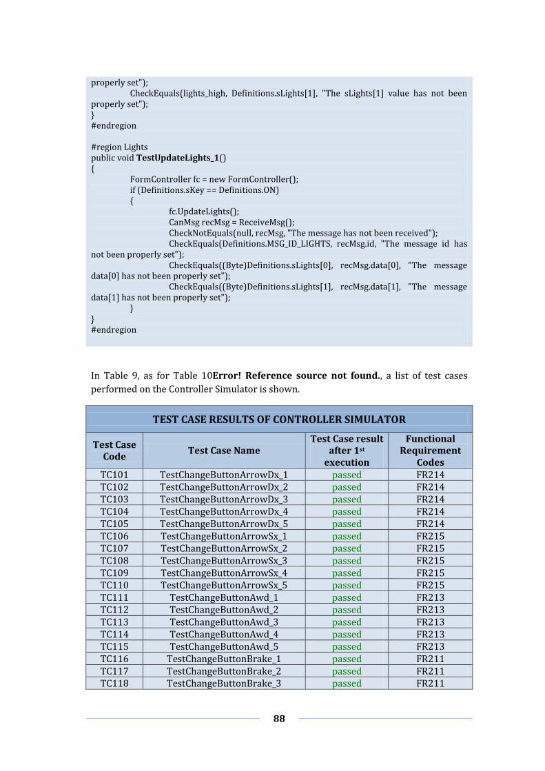
88
properly set"); CheckEquals(lights_high, Definitions.sLights[1], "The sLights[1] value has not been properly set"); } #endregion #region Lights public void TestUpdateLights_1() { FormController fc = new FormController(); if (Definitions.sKey == Definitions.ON) { fc.UpdateLights(); CanMsg recMsg = ReceiveMsg(); CheckNotEquals(null, recMsg, "The message has not been received"); CheckEquals(Definitions.MSG_ID_LIGHTS, recMsg.id, "The message id has not been properly set"); CheckEquals((Byte)Definitions.sLights[0], recMsg.data[0], "The message data[0] has not been properly set"); CheckEquals((Byte)Definitions.sLights[1], recMsg.data[1], "The message data[1] has not been properly set"); } } #endregion
In Table 9, as for Table 10Error! Reference source not found., a list of test cases
performed on the Controller Simulator is shown.
TEST CASE RESULTS OF CONTROLLER SIMULATOR
Test Case Code
Test Case Name Test Case result
after 1st execution
Functional Requirement
Codes TC101 TestChangeButtonArrowDx_1 passed FR214 TC102 TestChangeButtonArrowDx_2 passed FR214 TC103 TestChangeButtonArrowDx_3 passed FR214 TC104 TestChangeButtonArrowDx_4 passed FR214 TC105 TestChangeButtonArrowDx_5 passed FR214 TC106 TestChangeButtonArrowSx_1 passed FR215 TC107 TestChangeButtonArrowSx_2 passed FR215 TC108 TestChangeButtonArrowSx_3 passed FR215 TC109 TestChangeButtonArrowSx_4 passed FR215 TC110 TestChangeButtonArrowSx_5 passed FR215 TC111 TestChangeButtonAwd_1 passed FR213 TC112 TestChangeButtonAwd_2 passed FR213 TC113 TestChangeButtonAwd_3 passed FR213 TC114 TestChangeButtonAwd_4 passed FR213 TC115 TestChangeButtonAwd_5 passed FR213 TC116 TestChangeButtonBrake_1 passed FR211 TC117 TestChangeButtonBrake_2 passed FR211 TC118 TestChangeButtonBrake_3 passed FR211

89
TC119 TestChangeButtonBrake_4 passed FR211 TC120 TestChangeButtonBrake_5 passed FR211 TC121 TestChangeButtonEngine_1 passed FR209 TC122 TestChangeButtonEngine_2 passed FR209 TC123 TestChangeButtonEngine_3 passed FR209 TC124 TestChangeButtonEngine_4 passed FR209 TC125 TestChangeButtonEngine_5 passed FR209 TC126 TestChangeButtonHandBrake_1 passed FR210 TC127 TestChangeButtonHandBrake_2 passed FR210 TC128 TestChangeButtonHandBrake_3 passed FR210 TC129 TestChangeButtonHandBrake_4 passed FR210 TC130 TestChangeButtonHandBrake_5 passed FR210 TC131 TestChangeButtonHazardLights_1 passed FR216 TC132 TestChangeButtonHazardLights_2 passed FR216 TC133 TestChangeButtonHazardLights_3 passed FR216 TC134 TestChangeButtonHazardLights_4 passed FR216 TC135 TestChangeButtonHazardLights_5 passed FR216 TC136 TestChangeButtonKey_1 passed FR208 TC137 TestChangeButtonKey_2 passed FR208 TC138 TestChangeButtonKey_3 passed FR208 TC139 TestChangeButtonKey_4 passed FR208 TC140 TestChangeButtonKey_5 passed FR208 TC141 TestChangeButtonPto_1 passed FR212 TC142 TestChangeButtonPto_2 passed FR212 TC143 TestChangeButtonPto_3 passed FR212 TC144 TestChangeButtonPto_4 passed FR212 TC145 TestChangeButtonPto_5 passed FR212 TC146 TestSetGear_1 passed FR219 TC147 TestSetGear_2 passed FR219 TC148 TestSetGear_3 passed FR219 TC149 TestSetGear_4 failed FR219 TC150 TestSetGear_5 failed FR219 TC151 TestSetLightsStatus_1 passed FR217 TC152 TestSetLightsStatus_2 passed FR217 TC153 TestSetLightsStatus_3 passed FR217 TC154 TestSetLightsStatus_4 failed FR217 TC155 TestSetLightsStatus_5 failed FR217 TC156 TestSetThrottle_1 passed FR218 TC157 TestSetThrottle_2 passed FR218 TC158 TestSetThrottle_3 failed FR218 TC159 TestSetThrottle_4 failed FR218 TC160 TestUpdateArrowDx_1 passed FR215 TC161 TestUpdateArrowSx_1 passed FR214 TC162 TestUpdateAwd_1 passed FR213 TC163 TestUpdateEngine_1 passed FR209 TC164 TestUpdateGear_1 passed FR219 TC165 TestUpdateHandBrake_1 passed FR210 TC166 TestUpdateHazardLights_1 passed FR216 TC167 TestUpdateKey_1 passed FR208 TC168 TestUpdateLights_1 passed FR217

90
TC169 TestUpdatePto_1 passed FR212 TC170 TestUpdateThrottle_1 passed FR218
Table 9 – Results of test cases performed on the Controller Simulator.
In the case of the Controller Simulator 6 out of 70 test cases (8.57%) failed, while 3 out
of 23 tests related to functions (13.04%) failed. Moreover, the code coverage was 20
tested functions out of 23, which is 86.96%.
As discussed in previous chapters, by fixing all the discovered bugs would not
guarantee that the simulators are bug–free. In fact, it could be possible to implement
alternative test cases through which arise additional issues. In any case, despite its cost
and required efforts, the Unit testing demonstrated to be as very efficient for detecting
bugs at source code level.
Integration Testing
As described in Section 2.5.2, Integration testing enables the verification of correctness
relative to the integration of software components. In this section an excerpt of the
integration tests performed on the SUT is shown. In particular, Integration testing
regarded the same system components involved in the Unit testing. The underlying
purpose was to stress the fact that even though a component could result free of bugs
for certain test cases, it could show malfunctions under different testing conditions. The
underlying purpose was to stress the fact that even though a component could result
free of bugs for certain test cases, it could show malfunctions under different testing
conditions.
Since the communication between Display and Controller is available only via CAN bus
and by exchanging information through the On–Board Computer, the Integration
testing has also to include the On-Board Computer in the subsystem to test. In Table 10
are shown test cases performed on the Display, Controller and On–Board Computer
simulators to verify their integration. The first three columns represent the codes,
names and results of test cases, whereas the last column represents the functional
requirement codes related to simulators under test.
Test Case Code
Test Case Name Test Case
result after 1st execution
Functional Requirement Codes
TC201 TestCheckArrowDx_1 failed FR037 – FR118 – FR214 TC202 TestCheckArrowDx_2 passed FR038 – FR118 – FR214 TC203 TestCheckArrowSx_1 failed FR034 – FR119 – FR215 TC204 TestCheckArrowSx_2 passed FR035 – FR119 – FR215
TC205 TestCheckArrowDx_ArrowSx_1 passed FR036 – FR118 – FR119 –
FR214 – FR215
TC206 TestCheckArrowDx_ArrowSx_2 passed FR039 – FR118 – FR119 –
FR214 – FR215 TC207 TestCheckButtonAwd_1 passed FR032 – FR117 – FR213
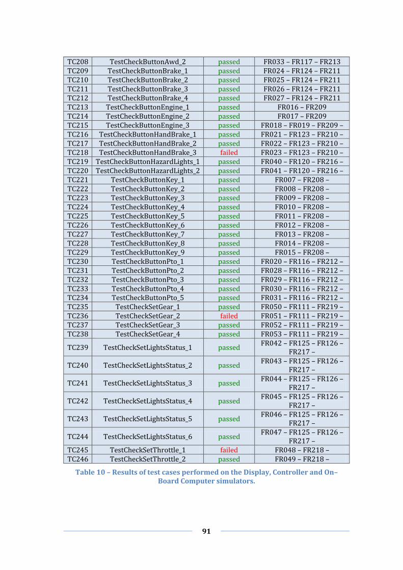
91
TC208 TestCheckButtonAwd_2 passed FR033 – FR117 – FR213 TC209 TestCheckButtonBrake_1 passed FR024 – FR124 – FR211 TC210 TestCheckButtonBrake_2 passed FR025 – FR124 – FR211 TC211 TestCheckButtonBrake_3 passed FR026 – FR124 – FR211 TC212 TestCheckButtonBrake_4 passed FR027 – FR124 – FR211 TC213 TestCheckButtonEngine_1 passed FR016 – FR209 TC214 TestCheckButtonEngine_2 passed FR017 – FR209 TC215 TestCheckButtonEngine_3 passed FR018 – FR019 – FR209 – TC216 TestCheckButtonHandBrake_1 passed FR021 – FR123 – FR210 – TC217 TestCheckButtonHandBrake_2 passed FR022 – FR123 – FR210 – TC218 TestCheckButtonHandBrake_3 failed FR023 – FR123 – FR210 – TC219 TestCheckButtonHazardLights_1 passed FR040 – FR120 – FR216 – TC220 TestCheckButtonHazardLights_2 passed FR041 – FR120 – FR216 – TC221 TestCheckButtonKey_1 passed FR007 – FR208 – TC222 TestCheckButtonKey_2 passed FR008 – FR208 – TC223 TestCheckButtonKey_3 passed FR009 – FR208 – TC224 TestCheckButtonKey_4 passed FR010 – FR208 – TC225 TestCheckButtonKey_5 passed FR011 – FR208 – TC226 TestCheckButtonKey_6 passed FR012 – FR208 – TC227 TestCheckButtonKey_7 passed FR013 – FR208 – TC228 TestCheckButtonKey_8 passed FR014 – FR208 – TC229 TestCheckButtonKey_9 passed FR015 – FR208 – TC230 TestCheckButtonPto_1 passed FR020 – FR116 – FR212 – TC231 TestCheckButtonPto_2 passed FR028 – FR116 – FR212 – TC232 TestCheckButtonPto_3 passed FR029 – FR116 – FR212 – TC233 TestCheckButtonPto_4 passed FR030 – FR116 – FR212 – TC234 TestCheckButtonPto_5 passed FR031 – FR116 – FR212 – TC235 TestCheckSetGear_1 passed FR050 – FR111 – FR219 – TC236 TestCheckSetGear_2 failed FR051 – FR111 – FR219 – TC237 TestCheckSetGear_3 passed FR052 – FR111 – FR219 – TC238 TestCheckSetGear_4 passed FR053 – FR111 – FR219 –
TC239 TestCheckSetLightsStatus_1 passed FR042 – FR125 – FR126 –
FR217 –
TC240 TestCheckSetLightsStatus_2 passed FR043 – FR125 – FR126 –
FR217 –
TC241 TestCheckSetLightsStatus_3 passed FR044 – FR125 – FR126 –
FR217 –
TC242 TestCheckSetLightsStatus_4 passed FR045 – FR125 – FR126 –
FR217 –
TC243 TestCheckSetLightsStatus_5 passed FR046 – FR125 – FR126 –
FR217 –
TC244 TestCheckSetLightsStatus_6 passed FR047 – FR125 – FR126 –
FR217 – TC245 TestCheckSetThrottle_1 failed FR048 – FR218 – TC246 TestCheckSetThrottle_2 passed FR049 – FR218 –
Table 10 – Results of test cases performed on the Display, Controller and On–Board Computer simulators.

92
As anticipated at the beginning of this section, the Integration testing has enhanced the
software quality. In fact, even if during the unit testing phase all bugged components
have been fixed, integration problems among software components could still exist. By
taking a closer look to the table, it is possible to notice that there exist failures of test
cases due to erroneous control of arrows activation and a missing check for the Hand
Brake. In addition, other bugs came out from a coding mistake of the Rear Gear and
Throttle functions.
To conclude, in this paragraph has been illustrated the relevant contribution of
Integration testing to the overall reliability of the system. Indeed, of 46 performed test
cases 5 failed, or in other words highlighted system problems. This means that after the
execution of the Integration testing has been possible to solve an additional 10.87% of
problems that affected the system.
System Testing
This section presents the execution of System testing to verify the correct behaviour of
the system. Differently to above presented methods, System testing takes care to run all
software components of the system to test its entirely. At this point it is worth recalling
the difference between Integration testing and System testing, since they could appear
quite similar at a first glance. At this point it is worth recalling the difference between
Integration testing and System testing, since they could appear quite similar at a first
glance.
TestComplete is a tool that supports both White–Box and Black–Box testing, therefore
it has been exploited to execute both code-driven and GUI testing in the System testing
phase. This choice has been made because the simulated environment consists of five
simulators where three of them are based on a GUI and the other two on the Win32
console application. Moreover, two different scripting languages have been adopted to
test the entire system: one using the C# scripting language and the other based on the
Record and Playback scripting notation.
Table 11 illustrates test cases performed on the entire system. The first three columns
represent the code, name and result of test cases; instead, the last column represents
codes of functional requirements related to all simulators under test.
Test Case Code
Test Case Name
Test Case result after
1st execution
Code of functional requirement
TC301 TestArrowDx_1 passed FR037 – FR118 – FR214 – FR319
– FR407 – FR440
TC302 TestArrowDx_2 passed FR038 – FR118 – FR214 – FR319
– FR407 – FR440
TC303 TestArrowSx_1 passed FR034 – FR119 – FR215 – FR318
– FR406 – FR439
TC304 TestArrowSx_2 passed FR035 – FR119 – FR215 – FR318
– FR406 – FR439

93
TC305 TestArrowDx_ArrowSx_1 passed FR036 – FR118 – FR119 – FR214
– FR215 – FR318 – FR319 – FR406 – FR407 – FR439 – FR440
TC306 TestArrowDx_ArrowSx_2 passed FR039 – FR118 – FR119 – FR214
– FR215 – FR318 – FR319 – FR406 – FR407 – FR439 – FR440
TC307 TestAwd_1 passed FR032 – FR117 – FR213 – FR317
– FR405 – FR438
TC308 TestAwd_2 passed FR033 – FR117 – FR213 – FR317
– FR405 – FR438
TC309 TestBrake_1 passed FR024 – FR124 – FR211 – FR315
– FR410 – FR411 – FR436
TC310 TestBrake_2 passed FR025 – FR124 – FR211 – FR315
– FR410 – FR411 – FR436
TC311 TestBrake_3 passed FR026 – FR124 – FR211 – FR315
– FR410 – FR411 – FR436
TC312 TestBrake_4 passed FR027 – FR124 – FR211 – FR315
– FR410 – FR411 – FR436
TC313 TestEngine_1 passed FR016 – FR209 – FR313 – FR402
– FR434
TC314 TestEngine_2 passed FR017 – FR209 – FR313 – FR402
– FR434
TC315 TestEngine_3 passed FR018 – FR019 – FR209 – FR313
– FR402 – FR434
TC316 TestHandBrake_1 passed FR021 – FR123 – FR210 – FR314
– FR409 – FR411 – FR435
TC317 TestHandBrake_2 passed FR022 – FR123 – FR210 – FR314
– FR409 – FR411 – FR435
TC318 TestHandBrake_3 failed FR023 – FR123 – FR210 – FR314
– FR409 – FR435
TC319 TestHazardLights_1 passed FR040 – FR120 – FR216 – FR320
– FR408 – FR441
TC320 TestHazardLights_2 passed FR041 – FR120 – FR216 – FR320
– FR408 – FR441
TC321 TestKey_1 passed FR007 – FR208 – FR312 – FR401
– FR433
TC322 TestKey_2 passed FR008 – FR208 – FR312 – FR401
– FR433
TC323 TestKey_3 passed FR009 – FR208 – FR312 – FR401
– FR433
TC324 TestKey_4 passed FR010 – FR108 – FR208 – FR312
– FR401 – FR433
TC325 TestKey_5 passed FR011 – FR208 – FR312 – FR401
– FR433
TC326 TestKey_6 passed FR012 – FR208 – FR312 – FR401
– FR433
TC327 TestKey_7 passed FR013 – FR208 – FR312 – FR401
– FR433
TC328 TestKey_8 passed FR014 – FR208 – FR312 – FR401
– FR433 TC329 TestKey_9 passed FR015 – FR208 – FR312 – FR401

94
– FR433
TC330 TestPto_1 passed FR020 – FR116 – FR212 – FR316
– FR404 – FR437
TC331 TestPto_2 passed FR028 – FR116 – FR212 – FR316
– FR404 – FR437
TC332 TestPto_3 passed FR029 – FR116 – FR212 – FR316
– FR404 – FR437
TC333 TestPto_4 passed FR030 – FR116 – FR212 – FR316
– FR404 – FR437
TC334 TestPto_5 passed FR031 – FR116 – FR212 – FR316
– FR404 – FR437 TC335 TestGear_1 passed FR050 – FR111 – FR219 – FR323 TC336 TestGear_2 passed FR051 – FR111 – FR219 – FR323 TC337 TestGear_3 passed FR052 – FR111 – FR219 – FR323 TC338 TestGear_4 passed FR053 – FR111 – FR219 – FR323
TC339 TestLights_1 passed FR042 – FR125 – FR126 – FR217
– FR321 – FR412 – FR442
TC340 TestLights _2 passed FR043 – FR125 – FR126 – FR217
– FR321 – FR412 – FR442
TC341 TestLights _3 passed FR044 – FR125 – FR126 – FR217
– FR321 – FR413 – FR442
TC342 TestLights _4 passed FR045 – FR125 – FR126 – FR217
– FR321 – FR413 – FR442
TC343 TestLights _5 passed FR046 – FR125 – FR126 – FR217
– FR321 – FR412 – FR413 – FR442
TC344 TestLights _6 passed FR047 – FR125 – FR126 – FR217
– FR321 – FR412 – FR413 – FR442
TC345 TestThrottle_1 passed FR048 – FR218 – FR322 – FR443 TC346 TestThrottle_2 passed FR049 – FR218 – FR322 – FR443
TC347 TestFan_1 passed FR057 – FR324 – FR403 – FR416
– FR444
TC348 TestFan_2 passed FR058 – FR324 – FR403 – FR416
– FR444
TC349 TestFan_3 failed FR059 – FR324 – FR403 – FR416
– FR444
TC350 TestBattery_1 passed FR054 – FR121 – FR329 – FR417
– FR426 – FR449
TC351 TestBattery_2 passed FR055 – FR121 – FR122 – FR417
– FR426 – FR449
TC352 TestBattery_3 failed FR056 – FR121 – FR329 – FR417
– FR426 – FR449
TC353 TestWaterTemperatur_1 passed FR060 – FR109 – FR325 – FR418
– FR419 – FR445
TC354 TestWaterTemperatur_2 passed FR061 – FR109 – FR325 – FR418
– FR419 – FR445
TC356 TestFuelLevel_1 passed FR062 – FR110 – FR326 – FR415
– FR420 – FR421 – FR446 TC357 TestFuelLevel_2 passed FR063 – FR110 – FR326 – FR415

95
– FR420 – FR421 – FR446
TC358 TestRPM_1 passed FR064 – FR112 – FR327 – FR422
– FR423 – FR447
TC359 TestKMH_1 passed FR065 – FR113 – FR328 – FR414
– FR424 – FR425 FR447 TC360 TestTimeDate_1 passed FR066 – FR115
Table 11 – Results of test cases performed on the entire system.
As noticed in the previous cases, by adopting additional testing techniques it is possible
to refine and deepen testing results, typically by covering shortcomings of other
approaches. In fact, by applying System testing there has been a 5% improvement of
the system quality. In particular, this testing case involved 60 test cases of which 3
failed.
96
Summary and Conclusions
The purpose of this experimental thesis is to enhance the capabilities of CCSimTech in
System testing. The fundamental task involved a survey on research literature in order
to learn and comprehend nowadays best practices in software testing. Moreover, this
work also required to collect industrial information, by interviewing employees in
different companies, about their common practices, needs, and limits. Eventually, the
thesis work resulted in the design and development of a demonstrator by using
CCSimTech able to meet industrial requirements by exploiting best practice techniques.
Going into more details, an important study has been conducted in evaluating different
testing notations and corresponding existing testing tools, available on the market. This
evaluation has mainly served to provide examples of how to test the SUT through
different testing techniques and methods. For the sake of simplicity, testing notations
have been divided into two categories, one representing general testing notation, and
the other for the TTCN-3 notation. During the analysis remarkable focus has been put
on the TTCN-3 notation, since recently it has become very popular in disparate
industrial application domains, such as telecommunication, automotive, etc. Since the
demonstrator involved the use of the CAN bus protocol in a simulated environment for
a vehicular application, the TTCN-3 notation appeared as the most suitable choice for
testing the system. However, when facing its practical usage for the design and
implementation of the demonstrator, it has been realized that the adoption of a general
notation would have been more suitable. Once a testing notation was identified, a
thorough investigation on available tools led us to the adoption of TestComplete to test
the demonstrator. The choice to use this tool came from its benefits that enable the
performance of Unit, Integration and System testing, openness to custom plug-ins,
excellent manufacturer’s support and familiarity in CrossControl’s employees.
Recently, companies specialized in producing systems that work in critical
environments have started to move from the traditional idea of performing software
testing on real hardware to more advanced approaches based on the execution of
software testing on simulated hardware. System Testing in a Simulated Environment is
an innovative approach that attempts to enhance the testing on an abstract model of a
particular system. This thesis reports the design and implementation of an abstract
model tailored to a vehicle working in a critical environment. The main purpose was to
highlight benefits and drawbacks of adopting a technique based on testing on a
simulated environment. Firstly, an important benefit is the possibility to execute test
cases that could be destructive for the SUT and dangerous for humans. This point
should not be underestimated because it enables testers to improve the quality of the
SUT covering much more particular and critical cases for the system at work, thus
promoting a better test coverage. Secondly, this approach permits to save development
time and costs by avoiding the need of buying the real hardware in order to test the
software. Thirdly, this technique has the potentials to speed up system development
and testing by enabling the independent realization of software and hardware. In fact,

97
development and testing are no more based on a selected target platform, but they can
leverage on a simulated environment.
Chapter 5 is a salient part of this thesis since it aims at bridging the analysis
(theoretical) part with the implementation (practical) part. The chapter describes the
state-of-practice related to CrossControl and its customers. Based on the testing
research background built-up in the first part of this report, it has been possible to
identify, design, and implement a demonstrator whose main purpose is to be a proof-
of-concept for future developments.
The second part of the thesis is more practical and devoted to the introduction of the
CCSimTech Simulated Environment. It illustrates basic concepts and architecture,
simulation components and simulation tools. This introduction has been useful to
understand the functionality of CCSimTech’s components and acquire familiarity with
them in order to integrate the demonstrator with CCSimTech. The CrossControl’s case
study represents the synthesis of development and testing analysis together with the
information collected during interviews. The case study is structured in two parts: the
first one describes the implementation of the simulated system; the second discusses
all testing techniques and methods applied on the demonstrator. A relevant outcome of
this thesis work is the analysis of results coming out of the performed tests, as
described in Section 6.2. In particular, by performing Unit testing, in the Display
Simulator and Controller Simulator have been discovered respectively the 4.84% and
8.57% of bugs (test failures). By executing Integration testing, 10.87% of problems
arose for the subsystem composed by Display, Controller, and On-Board Computer
simulators. Eventually, by means of System testing an additional 5% of bugs have been
detected as affecting the system as a whole. To conclude, testing practice is essential
during a system development to improve the system quality. Moreover, the exploitation
of different testing techniques and methods is also suggested since approaches
typically complement each other, allowing the detection of different kinds of bugs.

98
Future Works
This Chapter discusses future investigation directions as come out during the
realization of the work reported in this thesis. In particular, we discuss the
improvement of performance and reliability of CAN bus communication, and the
introduction of additional testing techniques in order to increase the number of tests
and consequently enhance the reliability of the simulated environment.
Integration between CCSimTech and TTCN–3 Architecture
In Section 3.2 and Chapter 4 both the TTCN-3 notation and the CCSimTech tool have
been deeply illustrated. Since TTCN–3 is becoming a de facto standard in different
domains, one of the challenges of CrossControl is the development of an interface for
the TTCN–3 architecture with the aim to make it compatible with the CCSimTech.
Andrus Lehtmets in [117] tried to illustrate and explain how it is possible to connect
the TTCN–3 architecture to a SUT. By analysing in depth the architecture depicted in
Figure 14 related to TTCN–3 is possible to conclude that one of the possible ways to
extend the TTCN–3 architecture functionalities is the implementation of an interface to
connect the SA with the SUT. The interface between the SA and SUT is called “SUT
interface”. Moreover, it would be necessary to implement the methods of the
ITriCommunicationSA interface (i.e. TriMap, TriUnmap, TriSend, TriExecuteTestCase,
TriEndTestCase, triMap) and ITriCommunicationTE interface (i.e. EnqueueMessage).
In addition to the creation of the SUT interface, a Codec component must be
implemented to support the communication between the architectures. As explained in
paragraph Codec of Section 3.2.2Error! Reference source not found., codecs are
necessary to encode and decode messages.
In this section a case study based on the current testing currently adopted in
CrossControl is illustred. In Figure 29 is depicted the architecture as mainly composed
by two blocks. The first block depicts the MS Visual Studio component that represents
the IDE used for developing and testing the SUT. As shown in the figure, it is
responsible of the manual testing execution. The second block shows the
CrossControl’s System, which includes three components. The component SimCAN is
responsible of the simulation of the CAN bus, whereas SimIO is responsible to enable
the simulation of the IO signals communication. Both are parts of the CCSimTech suite.
Finally, the component Simulated Hardware takes care of the simulation of the real
hardware of the SUT. In this case study this last component is available in three
different versions: CAN interface, CAN and IO interfaces, and IO interface.
The interfacing between Microsoft Visual Studio and SimCAN/SimIO components is
done in C++ and C#, due the availability of some libraries provided by CrossControl.
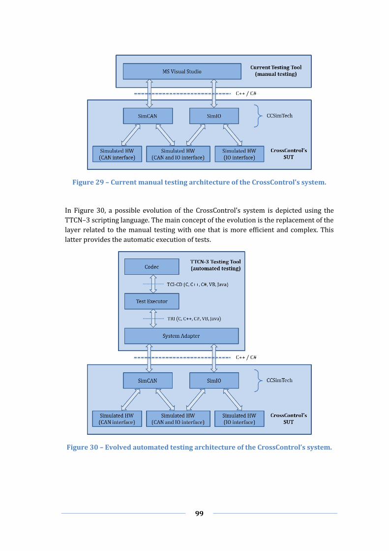
99
Figure 29 – Current manual testing architecture of the CrossControl’s system.
In Figure 30, a possible evolution of the CrossControl’s system is depicted using the
TTCN–3 scripting language. The main concept of the evolution is the replacement of the
layer related to the manual testing with one that is more efficient and complex. This
latter provides the automatic execution of tests.
Figure 30 – Evolved automated testing architecture of the CrossControl’s system.

100
As shown in the figure, the first block mainly represents the selected testing tool to
perform the testing on the SUT that in this case is the system developed by
CrossControl.
The first component, called Codec, contains all necessary codecs for the Test Executor
to encode and decode messages. The second component is called Test Executor and as
mentioned in paragraph Test Executable of Section 3.2.2 it is the engine that performs
the testing on the SUT. In addition, it takes care to query for each sent/received
message the Codec component in order to encode and decode messages that are on the
CAN bus. The last component is called System Adapter and is the main component that
allows the communication between the two blocks. In fact, through this component it is
possible to interface the TTCN–3 Testing Tool with the CrossControl’s System. On the
other hand, the second block is unvaried from the traditional to the evolved
architecture.
This approach offers the possibility to develop the interface between the two blocks in
different languages such as C, C++, C#, VB and Java. Since this case study has been made
considering the features of the TestCast tool, the availability of such a variety of
languages is due to the selected tool. Differently from the traditional architecture, the
implementation (development) of this architecture requires a greater initial effort
because TRI and TCI-CD interfaces have to be developed in addition to the CAN
interface. Also in this case the two interfaces can be developed with different
programming languages, such as C, C++, C#, VB and Java.
In Appendix D and Appendix E drafts are provided about how should be implemented
the TCI–CD and TRI interfaces, respectively, in order to allow the communication
between the two architectures. The programming language used in these excerpts of
code is C#.
Increasing and Improving the Software Testing
By referring to the case study of Chapter 5 and testing methods presented in Section
2.5 is noticeable that only few methods of the available ones have been adopted for
testing the SUT, which are Unit, Integration and System testing. Therefore, another
important future work could be the extension of the testing by trying to include as
many methods as possible. In particular, extending the available approaches with the
HIL method is really interesting given CrossControl involvement in the development of
techniques tailored to hardware located in critical environments. Moreover, in order to
improve the dependability of the CAN bus communication it will be also attractive to
introduce the Fault Injection testing to make the communication among system
components more secure and reliable. Besides, another interesting extension could be
the study of testing methods applied in each phase of the V–Model process.
Finally, the testing phases illustrated throughout this report only tackle the SUT
verification and neglect its validation. In this respect, future work has to be also
devoted to the introduction of acceptance testing to provide validation support.

101
References
[1] A. Bertolino, “Knowledge Area Description of Software Testing,” Pisa (Italy), 2001.
[2] IEEE, “IEEE Standard for Software Unit Testing,” 1986.
[3] IEEE, “IEEE Standard Glossary of Software Engineering Terminology,” 1990.
[4] L. Luo, “Software Testing Techniques,” Institute for Software Research International
Carnegie Mellon University, Pittsburgh (USA), 2001.
[5] D. A. U. Press, “System Engineering Fundamentals,” Fort Belvoir, 2001.
[6] A. Sato, M. Miki, T. Yamanouchi and M. Watanabe, “Software synthesis for trade-off
design,” Syracuse (USA), 2002.
[7] A. Felix, “Standard Approach to Trade Studies: A Process Improvement Model that
Enables Systems Engineers to ProvideInformation to the Project Manager by Going
Beyond the Summary Matrix,” Navair (CA), 2004.
[8] D. W. Hubbard, The Failure of Risk Management: Why It's Broken and How to Fix It,
John Wiley and Sons, 2009.
[9] Amirg, 2008. [Online]. Available: http://www.testingexcellence.com/v-model/.
[10] CrossControl, “Product Development Process,” 2010.
[11] . P. H. 2012. [Online]. Available: http://www.pmhut.com/cmm-and-project-quality-
management.
[12] J. Elfriede, G. Thom and G. Bernie, Implementing Automated Software Testing: How
to Save Time and Lower Costs While Raising Quality, Addison Wesley, 2009.
[13] A. Engel, Verification, Validation and Testing of Engineered Systems, John Wiley &
Sons, 2010.
[14] N. R. Pusuluri, Software Testing Concepts And Tools, Dreamtech Press, 2006.
[15] L. Williams, “Testing Overview and Black-Box Testing Techniques,” 2006.

102
[16] E. v. Veenendaal, “Standard glossary of terms used in Software Testing,” 2005.
[17] M. Fowler, March 2012. [Online]. Available: http://martinfowler.com/refactoring/.
[18] XQual, December 2011. [Online]. Available:
http://www.xqual.com/documentation/glossary.html.
[19] K. Beck, Test-driven development: by example, Addison-Wesley Professional, 2003.
[20] Sohel_Rana, December 2009. [Online]. Available:
http://www.codeproject.com/Articles/47747/Test-Driven-Development-TDD-Step-
by-Step-Part-1-In.
[21] Microsoft, March 2012. [Online]. Available: http://msdn.microsoft.com/en-
us/library/aa292128(v=vs.71).aspx.
[22] S. T. S. N. 2012 March. [Online]. Available: http://softwareqatestings.com/software-
testing-levels/testing-level-2-integration-testing.html.
[23] Exforsys, March 2011. [Online]. Available:
http://www.exforsys.com/tutorials/testing/system-testing-whywhathow.html.
[24] IEEE, “A Compilation of IEEE Standard Computer Glossaries,” New York, NY, 1991.
[25] Precision MBA, 2005. [Online]. Available:
http://www.precisionmba.com/hardware_in_the_loop.htm.
[26] ADI, 2007. [Online]. Available: http://www.adi.com/products_sim_qhil.htm.
[27] ADI, 2007. [Online]. Available: http://www.adi.com/products_sim_qhilWhy.htm.
[28] J. V. Carreira, D. Costa and J. G. Silva, in Fault injection spot-checks computer system
dependability, IEEE Spectrum, 1999, p. 50–55.
[29] A. Avizienis, J.-C. Laprie, B. Randell and C. Landwehr, in Basic Concepts and
Taxonomy of Dependable and Secure Computing, vol. I, IEEE, 2004, pp. 11-33.
[30] R. Kaksonen, “A Functional Method for Assessing Protocol Implementation Security,”
2001.
[31] A. Benso and P. Prinetto, Fault Injection Techniques and Tools for Embedded System
Reliability Evaluation, Springer, 2003.
[32] M.-C. Hsueh, T. K. Tsai and R. K. Iyer, “Fault Injection Techniques and Tools,” Urbana-
Champaign (USA), 1997.

103
[33] T. K. Tsai and R. K. Iyer, “FTAPE: A Fault Injection Tool to Measure Fault Tolerance,”
San Antonio, 1995.
[34] G. Kanawati, N. Kanawati and J. Abraham, in FERRARI: A Flexible Software-Based
Fault and Error Injection System, vol. 44, Austin (USA), IEEE Transactions on
Computers, 1995.
[35] R. Svenningsson, J. Vinter, H. Eriksson and M. Törngren, in MODIFI: A MODel-
Implemented Fault Injection Tool, vol. 6351, Springer, 2010, pp. 210-222.
[36] S. Han, K. Shin and H. Rosenberg, “DOCTOR: An IntegrateD SOftware Fault InjeCTiOn
EnviRonment for Distributed Real-time Systems,” Erlangen (GER), 1995.
[37] P. Marinescu and G. Candea, “LFI: A Practical and General Library-Level Fault
Injector,” Lisbon (POR), 2009.
[38] J. Carreira, H. Madeira and J. G. Silva, “Xception: Software Fault Injection and
Monitoring in Processor Functional Units,” Coimbra (POR).
[39] B. S. 2012. [Online]. Available: http://www.beyondsecurity.com/.
[40] S. I. 2011. [Online]. Available:
http://www.securityinnovation.com/holodeck/index.shtml.
[41] Codenomicon, 2012. [Online]. Available: http://www.codenomicon.com/defensics/.
[42] M. Dynamics, 2011. [Online]. Available: http://www.mudynamics.com/products/.
[43] B. E. Shilei Liu, “Generating Test Cases From Software Documentation,” 2001.
[44] M. Alam, “Software Test Automation Myths and Facts,” Dallas (USA).
[45] B. Pettichord, “Seven Steps to Test Automation Success,” San Jose (USA), 2001.
[46] Microsoft, 2012. [Online]. Available: http://xunit.codeplex.com/.
[47] P. Hamill, Unit test frameworks, O'Reilly Media, 2004.
[48] S. D. Ritchie, Pro .NET Best Practices, Apress, 2011.
[49] SeleniumHQ, 2012. [Online]. Available:
http://seleniumhq.org/docs/02_selenium_ide.html#selenium-commands-selenese.
[50] SeleniumHQ, 2012. [Online]. Available: http://seleniumhq.org/.

104
[51] A. Mockus, N. Nagappan and T. T. Dinh-Trong, “Test Coverage and Post-Verification
Defects: A Multiple Case Study,” 2009.
[52] S. Cornett, 2011. [Online]. Available:
http://www.bullseye.com/coverage.html#summary.
[53] Z. Chen, B. H. Yang and H. Chen, “Test Coverage Analysis Based on Program Slicing,”
in Information Reuse and Integration, IEEE International Conference on, 2003.
[54] K. J. Hayhurst, D. S. Veerhusen and L. K. R. John J. Chilenski, 2001. [Online]. Available:
http://shemesh.larc.nasa.gov/fm/papers/Hayhurst-2001-tm210876-MCDC.pdf.
[55] A. Geras, J. Miller, M. Smith and J. Love, “A survay of Test Notations and Tools for
Customer Testing,” in Extreme Programming and Agile Processes in Software
Engineering, Springer, 2005, pp. 109-117.
[56] AutoIt, 2012. [Online]. Available: http://www.autoitscript.com/site/autoit/.
[57] Parasoft, 2012. [Online]. Available:
http://www.parasoft.com/jsp/products/cpptest.jsp?itemId=47.
[58] Worksoft, 2012. [Online]. Available: http://www.worksoft.com/products/worksoft-
certify.html.
[59] Parasoft, 2012. [Online]. Available:
http://www.parasoft.com/jsp/products/dottest.jsp.
[60] TestPlant, 2012. [Online]. Available: http://www.testplant.com/products/eggplant/.
[61] FitNesse, 2012. [Online]. Available: http://www.fitnesse.org/.
[62] H.-P. D. C. 2012. [Online]. Available: http://www8.hp.com/us/en/software-
solutions/software.html?compURI=1172957.
[63] N. I. C. 2012. [Online]. Available: http://www.ni.com/labview/.
[64] Maveryx, 2012. [Online]. Available: http://www.maveryx.com/.
[65] Infragistics, 2012. [Online]. Available: http://www.infragistics.com/products/dotnet.
[66] S. S. 2012. [Online]. Available: http://www.seapine.com/qawizard.html.
[67] QFS, 2012. [Online]. Available: Seapine Software.
[68] Ranoxer, 2012. [Online]. Available: http://www.ranorex.com/.

105
[69] IBM, 2012. [Online]. Available: http://www-
01.ibm.com/software/awdtools/tester/functional/.
[70] IBM, 2012. [Online]. Available: http://www-
01.ibm.com/software/awdtools/tester/robot/index.html.
[71] OpenQA, 2012. [Online]. Available: http://seleniumhq.org/.
[72] M. F. 2012. [Online]. Available: http://www.borland.com/products/silktest/.
[73] Froglogic, 2012. [Online]. Available: http://www.froglogic.com/index.php.
[74] Telerik, 2012. [Online]. Available: http://www.telerik.com/automated-testing-tools/.
[75] S. S. 2012. [Online]. Available: http://smartbear.com/products/qa-tools/automated-
testing-tools.
[76] O. S. 2012. [Online]. Available: http://www.origsoft.com/products/testdrive/.
[77] A. A. 2012. [Online]. Available: http://www.automationanywhere.com/Testing/.
[78] M. F. 2012. [Online]. Available:
http://microfocus.com/products/TestPartner/index.asp.
[79] Tricentis, 2012. [Online]. Available: http://www.tricentis.com/en.
[80] T-Plan, 2012. [Online]. Available: http://www.t-plan.com/robot/index.html.
[81] PikeTec, 2012. [Online]. Available:
http://www.piketec.com/products/tpt.php?lang=en.
[82] M. C. 2012. [Online]. Available: http://www.microsoft.com/visualstudio/en-
sg/products/2010-editions/test-professional.
[83] Watir, 2012. [Online]. Available: http://watir.com/.
[84] E. T. S. I. “The Global Testing Language,” 2012.
[85] C. Willcock, S. Tobies, T. Deiss, S. Keil, F. Engler and S. Schulz, in An Introduction to
TTCN-3, John Wiley & Sons, 2011.
[86] C. Willcock, “Introduction to TTCN-3,” 2002.
[87] T. Technologies, 2012. [Online]. Available:
http://www.testingtech.com/ttcn3/introduction.php.

106
[88] 3GPP, 2012. [Online]. Available: http://www.3gpp.org/.
[89] O. 2012. [Online]. Available: http://www.openmobilealliance.org/.
[90] AUTOSAR, 2012. [Online]. Available: http://www.autosar.org/.
[91] W. Forum, 2012. [Online]. Available: http://www.wimaxforum.org/.
[92] K. Das, 2008. [Online]. Available: http://ipv6.com/articles/general/ipv6-the-next-
generation-internet.htm.
[93] NGN, 2012. [Online]. Available: http://www.ngn.ie/.
[94] Elvivor, “TTCN-3 External Interfaces”.
[95] OpenTTCN, 2010. [Online]. Available:
http://wiki.openttcn.com/media/index.php/OpenTTCN/Language_reference.
[96] I. T. U. “The Tree and Tabular Combined Notation version 3,” 2001.
[97] I. Schieferdecker and A. Rennoch, “Recent Developments on TTCN-3,” 2010.
[98] ETSI, “About TTCN-3,” 2012.
[99] U. o. S. a. T. o. C. 2010. [Online]. Available: http://ttcn.ustc.edu.cn/MainPageEn.html.
[100] BroadBit, 2012. [Online]. Available:
http://www.broadbit.com/page8/page2/page2.html.
[101] U. o. G. 2012. [Online]. Available: http://www.trex.informatik.uni-
goettingen.de/trac.
[102] U. o. G. 2012. [Online]. Available: http://t3tools.informatik.uni-
goettingen.de/trac/wiki/WikiStart.
[103] IRISA, 2009. [Online]. Available: http://www.irisa.fr/tipi/wiki/doku.php/t3devkit.
[104] MTP, 2010. [Online]. Available:
http://www.mtpinternational.co.uk/index.php?option=com_content&view=article&i
d=113&Itemid=117&lang=en.
[105] OpenTTCN, 2012. [Online]. Available:
http://www.openttcn.com/products/tester2012.
[106] Elvior, 2012. [Online]. Available: http://www.elvior.com/testcast/introduction.

107
[107] Pragmadev, 2012. [Online]. Available:
http://www.pragmadev.com/product/testing.html.
[108] T. Technologies, 2012. [Online]. Available:
http://www.testingtech.com/products/ttworkbench.php.
[109] Conformiq, 2012. [Online]. Available: http://www.conformiq.com/products/.
[110] All4Tec, 2012. [Online]. Available: http://www.all4tec.net/index.php/All4tec/matelo-
product.html.
[111] Elvior, 2012. [Online]. Available: TestCast Generator BETA.
[112] A. Öberg, 2011. [Online]. Available: http://oske-net-
bin.directo.fi/@Bin/0650fc8c225caad174e7f8959574081a/1333097622/application/
pdf/509084/Anders%20%C3%96berg%20CrossControl.pdf.
[113] A. Möller and P. Åberg, “A Simulation Technology for CAN-Based Systems,” 2004.
[114] C. Tutorial, 2012.
[115] C. I. A. 2011. [Online]. Available: http://www.can-cia.de/index.php?id=161.
[116] C. Paulsson, “COMPONENT-BASED BASE-PLATFORM,” Västerås (SWE), 2007.
[117] A. Lehtmets, “TTCN-3 in end-to-end model based testing explained on a case study,”
2010.
[118] Elvivor, Tutorial: How to set up TTCN-3 environment (C# version), 2012.

108
Appendix A – Comparison Matrix of General Testing Tools
NAME SUPPORTED TESTING TYPES
IDE APPLICATION AREAS SUPPORTED OPERATING SYSTEMS
MINIMUM HW REQUIREMENTS
AVAILABILITY OF EXTENSIONS / PLUG–INS
VERSION LICENSE PRICE VENDOR
AutoIt Based on the free SciTE editor
.NET; VB; Web Browsers
MS Windows XP, 2003, Vista, Win 7, 2008 R2
3.3.8.1
General Public
License (GNU)
FREE Jonathan
Bennett & AutoIt Team
C/C++TEST
Functional Testing; Unit Testing; Load/Performance Testing; End–to–end Testing; Advanced web app Testing; Security Testing; Continuous regression Testing; Data–driven Testing
Eclipse IDE for C/C++; MS Visual Studio for Visual C++; Wind River Workbench; ARM Workbench IDE for RVDS; QNX Momentics IDE; Texas Instruments Code Composer Studio
C/C++;
MS Windows NT, 2000, XP, 2003, Vista, Win 7; Linux kernel 2.4 or higher with glibc 2.3 or higher and an x86–compatible processor; Linux kernel 2.6 or higher with glibc 2.3 or higher and an x86_64–compatible processor; Solaris 7, 8, 9, 10 and an UltraSPARC processor; IBM AIX 5.3; PowerPC processor
Pentium 4/M or equivalent; 1 GB of RAM
9.2.2.17 Commercial € 3000 + 600 (assistence)
Parasoft
Certify
HTML; .NET; Visual Basic, Java; UNIX; C++,
MSƒ Windows XP Pro, Vista, Server 2003, Win 7;
Pentium 4/M or equivalent; 2 GB of RAM; 750 MB of free disk space
8.6 Commercial Worksoft
dotTEST
Functional Testing; Unit Testing; Load/Performance Testing; End–to–end Testing; Advanced web app Testing; Security Testing; Continuous
MS Visual Studio .NET (C#, VB.NET, ASP.NET and Managed C++)
MS Windows 2003 Server, XP, Vista, Win 7
Pentium 4/M or equivalent; 1 GB of RAM
9.4.0 Commercial € 3000 + 600 (assistence)
Parasoft

109
regression Testing; Data–driven Testing
FitNesse
Acceptance Testing; Performance Testing; Regression Testing
FitNess
C++; C#; Python; Ruby; Delphi
MS Windows; All POSIX (Linux/BSD/UNIX–like OSes)
YES 20111026
Common Public
License (GPL)
FREE
HP Unified Functionl Testing software
Functional Testing; Unit Testing; Service Testing; Load Testing; Regression Testing
HP Unified Functionl Testing
Web browsers (Internet Explorer, Firefox, Chrome) Java (Core and Advanced); .Net; WPF; SAP; Oracle; Siebel; PeopleSoft; Delphi; Power Builder; Stingray 1; Terminal Emulator: Flex; Web Services; Windows Mobile; VisualAge Smalltalk; MS Silverlight
MS Windows XP SP2 (32–64–bit), Vista SP1 (32–64–bit), Win 7 (32–64–bit), Server 2003 SP2 (32–64–bit), Server 2008 (32–64–bit)
Pentium 4/M or equivalent; 1 GB of RAM; 1 GB of free disk space
11 Commercial HP Software
Division
IBM Rational Functional Tester
Functional Testing; Regression Testing; GUI Testing; Data–driven Testing
Eclipse
Java; Web 2.0; SAP; Siebel; .NET (C++, VB.NET); C++; Delphi
Linux; MS Windows
8.2.1 Commercial SEK 31973 /
129861 IBM Rational
IBM Rational Robot
Functional Testing; .NET (C#, VB.NET); C/C++; Delphi
MS Windows 2000, 2003, 98, Me, NT, XP, 2008, Vista, Win 7
7.0.2 Commercial IBM Rational
LabVIEW HIL Testing; Unit Testing.
LavVIEW; MS Visual Studio
C/C++;
MS Windows XP (32bit), Vista (SP1 – SP2), Win 7, Server 2003 and 2008 R2 (32bit), Server 2008 R2 (64–bit);
Pentium 4/M or equivalent; 1 GB of Ram; 3.3 GB of disk space (Windows); 1.2 GB of disk space
2011 Commercial SEK 12699 /
27300 / 45499
National Instruments

110
MAC Intel Processors (partially); Linux (Red Hat and SUSE) (partially).
(MAC); 1.2 GB of disk space (Linux).
Maveryx
Functional Testing; Regression Testing; GUI Testing; Data–driven Testing
Eclipse; NetBeans; JUnit; IBM Rational Functional Tester
Java
MS Windows XP, Vista, Win 7; Unix (Linux); Mac OS X.
Eclipse 1.3.0
GNU General Public
License v2.0
FREE Maveryx
QA Wizard Pro Functional Testing; Load Testing; Data–driven Testing
QA Wizard Pro
Java; Flash; HTML 5; JavaScript; MS Silverlight; C++; C#; VB.NET; Win32; QT; AJAX; ActiveX; Infragistics Windows Forms controls
MS Windows XP SP2 and later, Server 2003 SP1 and later, Vista, Server 2008, Win 7
Pentium 4/M or equivalent; 1 GB of RAM
2012.0.0 Commercial
Dedicated: € 150 (Pro
OCR Add–on) / 495
(Pro Standard) / 1495 (Pro–RunTime);
Floating: € 300 (Pro
OCR Add–on) / 995
(Pro Standard) / 2995 (Pro–RunTime);
Seapine
QF–Test Regression Testing; Load Testing.
Eclipse
AJAX; Web 2.0 applications; Swing; SWT; Eclipse plugins; RCP applications; ULC; CaptainCasa; Java applets; Java WebStart; Internet Explorer; Firefox
MS Windows; Unix
Eclipse 3.4.7 Commercial € 1995 /
2495 / 2995
Quality First Software
GmbH
Ranorex
Regression Testing; Unit Testing (requires Visual Studio)
Ranorex Studio; MS Visual Studio
.NET (C#, VB.NET); Win32; MFC; WPF (XAML); QT;
MS Windows XP, Server 2003 or 2008, Vista, Win 7
Pentium 4/M or equivalent; 256 MB of RAM; 280 MB of disk space (32bit);
No documentation to create Custom Ranorex Plug–ins
3.2.3 Commercial
€ 389 / 980 / 1480 (node–locked);
€ 780 / 2080
Ranorex GmbH
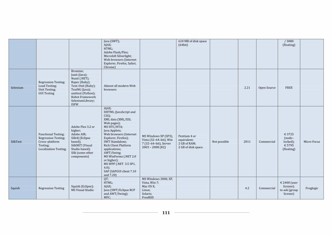
111
Java (SWT); AJAX; HTML; Adobe Flash/Flex; Microfoft Silverlight; Web browsers (Internet Explorer, Firefox, Safari, Chrome)
610 MB of disk space (64bit)
/ 3080 (floating)
Selenium
Regression Testing; Load Testing; Unit Testing; GUI Testing
Bromine; Junit (Java); Nunit (.NET); Rspec (Ruby); Test::Unit (Ruby); TestNG (Java); unittest (Python); Robot Framework SeleniumLibrary; ISFW
Almost all modern Web browsers
2.21 Open Source FREE
SilkTest
Functional Testing; Regression Testing; Cross–platform Testing; Localization Testing;
Adobe Flex 3.2 or higher; Adobe AIR; Silk4J (Eclipse based); SilkNET (Visual Studio based); Silk (some other components)
AJAX; DHTML (JavaScript and CSS); XML data (XML/XSL Web pages); MS HTC/HTA; Java Applets; Web browsers (Internet Explorer, Firefox); SWT Standalone; Rich Client Platform applications; AWT/Swing; MS WinForms (.NET 2.0 or higher); MS WPF (.NET 3.5 SP1, 4.0); SAP (SAPGUI client 7.10 and 7.20)
MS Windows XP (SP3), Vista (32–64–bit), Win 7 (32–64–bit), Server 2003 – 2008 (R2)
Pentium 4 or equivalent; 2 GB of RAM; 2 GB of disk space.
Not possible 2011 Commercial
€ 3725 (node–locked); € 5795
(floating)
Micro Focus
Squish Regression Testing Squish (Eclipse); MS Visual Studio
QT; HTML; AJAX; Java (SWT/Eclipse RCP and AWT/Swing); MFC;
MS Windows 2000, XP, Vista, Win 7; Mac OS X; Linux; Solaris; FreeBSD
4.2 Commercial
€ 2400 (user license);
to ask (group license)
Froglogic

112
.NET; C/C++;
T–Plan Robot
Object Oriented Testing; Image Based Testing; Mobile Testing; Browser Testing; Gaming Testing
T–Plan Robot
Java; C++; C#; .NET; Flash; HTML; Flex; Jquery and AJAX; MS Silverlight; Mobile phones (iPhone, Android, Windows Mobile, Symbian, BlackBerry); Web browsers (Internet Explorer, Firefox, Safari, Chrome); Satellite and GPS (GPS systems, radar targetting, defence systems, flight simulators, command and control)
MS Windows; Linux; Mac; Solaris; Chrome OS
Pentium 4/M or equivalent; 1 GB of RAM; 200 MB of disk space
YES 2.3.4 Commercial T–Plan
Test Studio
Functional Testing; Performance Testing; Load Testing; Mobile Testing
Test Studio; MS Visual Studio
HTML; AJAX; WPF; MS Silverlight; ASP.NET MVC; JavaScript; iOS; Web browsers (Internet Explorer, Firefox, Safari)
MS Windows XP, Vista, Server 2003 – 2008, Win 7
Pentium 4/M or equivalent; 2 GB of RAM; 500 MB of disk space
2011.2 Commercial $ 2,499
(multi–user) Telerik
TestAdvantage 2011 Vol.
2 Commercial Infragistics
TestComplete
Functional (or GUI) Testing; Regression Testing; Unit Testing; Keyword Testing; Web Testing; Distributed Testing; Functional and Load
MS Visual Studio; Delphi C++Builder Adobe Flash[3] Adobe Flex Adobe AIR MS Silverlight
.NET (C#, VB.NET, JScript.NET, VCL.NET, C#Builder, Python .NET, Perl .NET etc.) WPF; Java (AWT, SWT, Swing, WFC) Sybase PowerBuilder,
MS Windows XP (32–64–bit), Win 7 (32–64–bit), Vista (32–64–bit), Server 2008 R2 (64bit), Server 2003 and 2008 (32–64–bit), Embedded
Pentium 4/M or equivalent; 256 MB of RAM, 700 MB of disk space;
Custom plug–ins can be developed and attached for additional enhanced functionalities (Visual C++, C#, Delphi);
8.7 Commercial
$ 999 / 2999 (Standard);
$ 1999 / 4499
(Enterprise)
SmartBear Software

113
Testing of web services; Coverage Testing; Data–Driven Testing
MS FoxPro, MS Access, MS InfoPath Web browsers (Internet Explorer, Firefox, Netscape Navigator) Flash; Flex
Standard Win 7 (32–64–bit), Embedded Standard 2009 (with the Add Hardware Control Panel component installed)
Light–weight script extensions that are created with VBScript or JScript.
TestDrive Regression Testing; Java; Flash/Flex; Web Services
Original
Testing Anywhere
Automated Software Testing; Distributed Load Testing; Automated Web Testing; Regression Testing; Functional Testing; Black–Box; Testing; Acceptance Testing; Keyword–driven Testing; Unit Testing; Data–Driven Testing; Smoke Testing; Integration Testing; Compatibility Testing; Performance Testing; System Testing; GUI Testing; Automated Flex Testing; Java application Testing; Silverlight Testing; Third–party .NET supported Testing; Mainframe application Testing; WPF Testing
MS Visual C#; MS Visual C++; MS Visual Basic; MS Silverlight; Sun JRE; Adobe Flash; MS Office Access
VB.NET; C#; C++; Win32; VB6; AJAX; ActiveX; JavaScript; HTML; Delphi; Java; Perl; 32 bit apps; 64 bit apps; Oracle Forms; PHP; Python; .NET; Silverlight; WPF; Macromedia Flash 1.0–8.0; Adobe Flash 9.0 & later; Web browsers (Internet Explorer, Firefox, Opera, Safari, Chrome)
MS Windows XP SP2 (32–64–bit), Vista (32–64–bit), Win 7 (32–64–bit), Server 2008 R2, Server 2003,
7 Commercial
$ 2500 (single user)
$ 7000 (multi–user)
Automation Anywhere

114
TestPartner Regression testing MS Visual Studio
.NET; Java; SAP; Oracle; Windows–based applications; Web browsers (Internet Explorer, Firefox)
MS Windows 7 Pro, Enterprise, and Ultimate (32–64–bit); MS Windows Vista Business, Enterprise, and Ultimate SP1, SP2 (32–bit); MS Windows XP Pro SP3 (32–bit); MS Windows Server 2008 Standard and Enterprise SP1, SP2, and R2 (32–64–bit); MS Windows Server 2003 Standard and Enterprise SP1, SP2, and R2 (32–bit);
Pentium 4 or equivalent 512 MB of RAM 300 MB of disk space; 1024 x 768 or higher screen resolution
6.3 Commercial Micro Focus
TestPlant
Flash; Java; HTML; .Net; MS Silverlight
MS Windows XP, Vista, and Win 7; Mac OS X 10.4 and higher; Linux (Debian 5+, Ubuntu 8.04+, RedHat 5+, Fedora 9+, CentOS 5+)
11.22 Commercial TestPlant
TOSCA Testsuite
Agile Testing; Datawarehouse Testing; GUI & Non–GUI Testing; Load Testing; Mobile Testing; Model–Based Testing; Regression Testing; SAP Testing; XBrowser Testing
Web browsers (Internet Explorer, Firefox)
MS Windows XP SP2 and above, Vista SP2, 7 (32–64–bit)
Pentium 4 or equivalent; 1 GB of RAM; 1 GB of free disk space; 100 Mb/s of Network speed
7.3.1[3] Commercial TRICENTIS
Technology & Consulting
TPT
Model–in–the–loop Testing; Software–in–the–loop Testing; Hardware–in–the–loop Testing;
TPT
MATLAB/Simulink models; TargetLink models; ASCET; C–Code; DaVinci;
YES 4 Commercial PikeTec GmbH

115
Unit Testing; Integration Testing; System Testing; Regression Testing; end–to–end Testing
SystemDesk; CAN; LIN; INCA; LABCAR
Visual Studio Test Professional
Regression Testing;
MS Visual Studio; Expression Blend; Expression Web; Robotics Developer; Studio SharePoint Designer; FrontPage; Small Basic WebMatrix
Visual Basic; Visual Basic .NET; Visual C++; Visual C#; Visual J#; Visual FoxPro; IronPython; IronRuby; PowerShell; XAML; F#
MS Windows XP SP3 (32–bit), Vista SP1 (32–64–bit), Win 7 (32–64–bit), Server 2003 SP2 (32–64–bit), Server 2003 R2 (32–64–bit), Server 2008 SP2 (32–64–bit), Server 2008 R2 (64–bit)
Pentium 4/M or equivalent; 1 GB (32 Bit) or 2 GB (64 Bit) of RAM; 3 GB of disk space
2010 Commercial
To see the prices about Visual Studio
to this link
http://msdn.MS.com/subscriptions/hh442902.asp
x
Microsoft
WATIR RubyMine; NetBeans
Web browsers (Internet Explorer, Firefox, Opera, Safari, Chrome)
MS Windows XP Pro SP3, Vista Ultimate (32–bit), Win 7 Pro SP1 (32–bit); Mac OS X 10.5 and higher; Ubuntu Linux
Pentium 4/M or equivalent; 1 GB of RAM
YES 3 BSD license FREE –––

116
Appendix B – Comparison Matrix of TTCN–3 Testing Tools
NAME SUPPORTED INTERFACES LANGUAGES
IDE SUPPORTED PROTOCOLS
SUPPORTED OPERATING SYSTEMS
MINIMUM HW VERSION LICENSE PRICE VENDOR
Open Source
LoongTesting 2010–9–28 Open Source FREE
University of Scince and
Technology of China
BroadBit Test Tool GSM, UMTS, VoIP, ISDN, WiFi, and cordless telephony (DECT)
Linux; OpenSolaris; Microsoft Windows; Mac OS X (Snow Leopard)
PHP installer 1.4 GNU General
Public License (GPL)
FREE BroadBit
TRex Eclipse Microsoft Windows (32–bit); Linux (32–bit)
Eclipse 3.4; Java JRE 5
4.1.1 Eclipse Public
License FREE
University of Göttingen
T3DevKit C++, Java
Pitticon; Telelogic Tester; TTCN–3 Toolbox; Eclipse
Microsoft Windows (32–64–bit); Linux (32–bit)
Python 2.0; Flex; Bison
0.11.0 CeCILL–C FREE Inria
Commercial Compilers and Interpreters
Exhaustif TTCN C++ Exhaustif TTCN
Microsoft Windows (32–bit); Linux (32–bit); Solaris (32–bit)
Commercial MTP
OpenTTCN Tester C, C++, .NET (C# and VB), Java
OpenTTCN (Eclipse–based)
3GPP, LTE, WiMAX, IPv6, 3GPP, 3G, Bluetooth, DSRC, GSM
Microsoft Windows XP, Vista, Win 7; Linux
.NET 3.5 or higher for Windows; Mono 2.6.7 or higher for Linux
4.2.0 Commercial
€ 2900 (Node–locked, Standard
Edition); € 4900 (Node–
locked, Professional Edition)
OpenTTCN
TestCast C, C++, .NET (C# and VB), Java
TestCast Microsoft Windows (32–64–bit); Linux (32–64–bit)
.NET 3.5 or higher for Windows; Mono 2.6.7 or higher
6.5.1 Commercial € 100 (1 week) up to
€ 2000 (1 year); € 5900 (permanent)
Elvior

117
for Linux
Real Time Developer Studio
C++ RTDS 4.3 Commercial
€9,000 (floating licence);
€1,710 (yearly maintenance)
Pragmadev
TTworkbench C, Java TTworkbench (Eclipse–based); GFT–Editor
ASN.1, CAN, Ethernet, FTP, GPIB, HP Quality Center, HTTP, IDL, IP, LTE, RRC/S1/X2, MOST, Native C, Protobuf, Release Management, RS232, SCP, SNMP, SQL, SSH, TCP, Telnet, TLS, Ttmex, UDP, WSDL, XSD
Microsoft Windows XP, Vista, 7 (32–64–bit); Linux (GTK, 32–64–bit)
Eclipse 14 Commercial Testing
Technologies
Commercial Generators
Conformiq
Python, TCL, TTCN–3, C, C++, Visual Basic, Java, JUnit, Perl, Excel, HTML, Word, Shell Scripts and others
Conformiq Modeler; Conformiq (Eclipse–based)
Microsoft Windows XP, Vista, Win 7; Recent Linux distribution (32–64–bit)
2 GHz of CPU; 1 GB of RAM; 200 MB of free disk space;
4.4.2 Commercial X Conformiq
All4Tec MaTeLo
C, C#, python, java, Visual Basic, Perl, Ruby,TCL, CAPL, CVS and others
Matelo Microsoft Windows XP, Vista (32–64–bit), Win 7 (32–64–bit)
4.7.6 Commercial X All4Tec
TestCast Generator TestCast (Eclipse–based)
Microsoft Windows (32–bit); Linux (32–bit)
BETA Commercial X Elvior

118
Appendix C – TCI–CD Implementation
Below is shown an extract of code of the TCI–CD Implementation taken by the tutorial
of TestCast [118].
using System; using System.Collections; using System.Text; using System.IO; namespace Elvior.Thermometer { public abstract class ThermometerMsg { public const int INT_LENGTH = 4; public abstract uint MsgCode { get; } public abstract bool Decode(byte [] ayData); protected abstract byte[] EncodeProc(); public byte[] Encode() { byte [] ayPayload = EncodeProc(); MemoryStream ms = new MemoryStream(); // write message code byte [] ayTmp = BitConverter.GetBytes(MsgCode); ms.Write(ayTmp, 0, ayTmp.Length); // write message length ayTmp = BitConverter.GetBytes(ayPayload == null ? (int)0 : ayPayload.Length); ms.Write(ayTmp, 0, ayTmp.Length); // write payload if (ayPayload != null && ayPayload.Length > 0) ms.Write(ayPayload, 0, ayPayload.Length); return ms.ToArray(); } } public class TempRequest : ThermometerMsg { public const uint CODE = 0x01; public override uint MsgCode { get { return CODE; } } public override bool Decode(byte[] ayData) { return ayData.Length == 0; } protected override byte[] EncodeProc() { return null; }

119
} public class TempReply : ThermometerMsg { public const uint CODE = 0x02; public override uint MsgCode { get { return CODE; } } private int m_temperature; public int TemperatureValue { get { return m_temperature; } set { m_temperature = value; } } public override bool Decode(byte[] ayData) { if (ayData.Length != 4) return false; m_temperature = BitConverter.ToInt32(ayData, 0); return true; } protected override byte[] EncodeProc() { return BitConverter.GetBytes(m_temperature); } } public class HumRequest : ThermometerMsg { public const uint CODE = 0x03; public override uint MsgCode { get { return CODE; } } public override bool Decode(byte[] ayData) { return ayData.Length == 0; } protected override byte[] EncodeProc() { return null; } } public class HumReply : ThermometerMsg { public const uint CODE = 0x04; public override uint MsgCode {
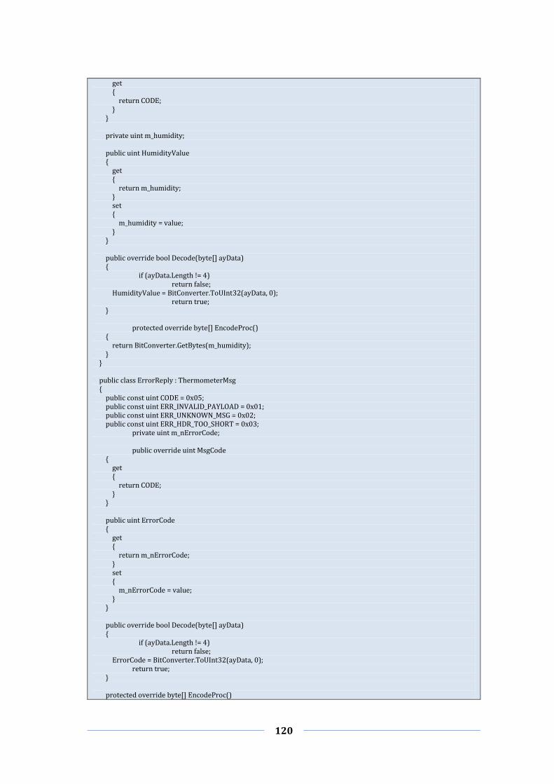
120
get { return CODE; } } private uint m_humidity; public uint HumidityValue { get { return m_humidity; } set { m_humidity = value; } } public override bool Decode(byte[] ayData) { if (ayData.Length != 4) return false; HumidityValue = BitConverter.ToUInt32(ayData, 0); return true; } protected override byte[] EncodeProc() { return BitConverter.GetBytes(m_humidity); } } public class ErrorReply : ThermometerMsg { public const uint CODE = 0x05; public const uint ERR_INVALID_PAYLOAD = 0x01; public const uint ERR_UNKNOWN_MSG = 0x02; public const uint ERR_HDR_TOO_SHORT = 0x03; private uint m_nErrorCode; public override uint MsgCode { get { return CODE; } } public uint ErrorCode { get { return m_nErrorCode; } set { m_nErrorCode = value; } } public override bool Decode(byte[] ayData) { if (ayData.Length != 4) return false; ErrorCode = BitConverter.ToUInt32(ayData, 0); return true; } protected override byte[] EncodeProc()

121
{ return BitConverter.GetBytes(ErrorCode); } } }

122
Appendix D – TRI Implementation
Below is shown an extract of code of the TRI Implementation taken by the tutorial of
TestCast [118].
using System; using System.Collections; using System.Text; using Etsi.Ttcn3.Tri; using TestCast.Ttcn3.TriTci; using System.Threading; namespace Elvior.Thermometer { class Comm : ITriCommunicationSA, ITriPlatformPA, IChannelEventHandler { private const string SENT = "sent"; private const string RECEIVED = "received"; private const int MESSAGE_HEADER_LENGTH = 8; private Analyzer m_analyzer; private AutoResetEvent m_evDone = new AutoResetEvent(false); public Comm() { m_analyzer = new Analyzer(); TriProvider.Instance.TriCommunicationSA = this; TriProvider.Instance.TriPlatformPA = this; TriTciChannel.Instance.ApplicationName = "Thermometer"; TriTciChannel.Instance.EventHandler = this; } public void Run() { if (!TriTciChannel.Instance.Open()) { Console.WriteLine("Error opening TRI channel"); return; } m_evDone.WaitOne(); } private void PrintInfo(byte[] ayMsg, string sActionName) { uint nMsgCode = 0; if (ayMsg.Length >= 4) nMsgCode = BitConverter.ToUInt32(ayMsg, 0); string sMessageName = ""; if (nMsgCode == TempRequest.CODE) sMessageName = "TempRequest"; else if (nMsgCode == TempReply.CODE) sMessageName = "TempReply"; else if (nMsgCode == HumRequest.CODE) sMessageName = "HumRequest"; else if (nMsgCode == HumReply.CODE) sMessageName = "HumReply"; else if (nMsgCode == ErrorReply.CODE) sMessageName = "ErrorReply"; else sMessageName = "unknown"; Console.WriteLine( sActionName + " " + sMessageName + " (message code " + nMsgCode + ")"); } public void SendMessage(byte[] ayData) {

123
PrintInfo(ayData, SENT); ITriMessage msgToSend = TriProvider.Instance.TriFactory.CreateMessage(); msgToSend.EncodedMessage = ayData; TriProvider.Instance.TriCommunicationTE.EnqueueMessage(m_tsiPortId, null, m_componentId, msgToSend); } #region ITriCommunicationSA Members private ITriComponentId m_componentId; private ITriPortId m_tsiPortId; public TriStatus TriMap(ITriPortId compPortId, ITriPortId tsiPortId) { //saving values that are later needed in triSend //see step #5 under chapter "Step 1: System and Platform Adapter" from the doc m_componentId = compPortId.Component; m_tsiPortId = tsiPortId; return TriStatus.TriOk; } //Thermometer has received a message private void ProcessReceivedMessage(byte[] ayMsg) { PrintInfo(ayMsg, RECEIVED); int nMsgLen = ayMsg.Length; ThermometerMsg msg; if (nMsgLen < MESSAGE_HEADER_LENGTH) { //Error: message size is smaller than the header size should be msg = m_analyzer.CreateErrorMsg(ErrorReply.ERR_HDR_TOO_SHORT); } else { uint nMsgCode = BitConverter.ToUInt32(ayMsg, 0); int nPayloadLen = BitConverter.ToInt32(ayMsg, 4); byte[] ayPayload = new byte[nPayloadLen]; Buffer.BlockCopy(ayMsg, MESSAGE_HEADER_LENGTH, ayPayload, 0, nPayloadLen); msg = m_analyzer.AnalyzeMsg(nMsgCode, ayPayload); } SendMessage(msg.Encode()); } public TriStatus TriSend(ITriComponentId componentId, ITriPortId tsiPortId, ITriAddress address, ITriMessage sentMessage) { ProcessReceivedMessage(sentMessage.EncodedMessage); return TriStatus.TriOk; } #region Remaining SA methods public TriStatus TriCall(ITriComponentId componentId, ITriPortId tsiPortId, ITriAddress sutAddress, ITriSignatureId signatureId, ITriParameterList parameterList) { return TriStatus.TriOk; } public TriStatus TriCallBC(ITriComponentId componentId, ITriPortId tsiPortId, ITriSignatureId signatureId, ITriParameterList parameterList) { return TriStatus.TriOk; } public TriStatus TriCallMC(ITriComponentId componentId, ITriPortId tsiPortId, ITriAddressList sutAddresses, ITriSignatureId signatureId, ITriParameterList parameterList) { return TriStatus.TriOk; }

124
public TriStatus TriExecuteTestCase(ITriTestCaseId testCaseId, ITriPortIdList portIdList) { return TriStatus.TriOk; } public TriStatus TriEndTestCase() { return TriStatus.TriOk; } public TriStatus TriSendBC(ITriComponentId componentId, ITriPortId tsiPortId, ITriMessage sentMessage) { ProcessReceivedMessage(sentMessage.EncodedMessage); return TriStatus.TriOk; } public TriStatus TriSendMC(ITriComponentId componentId, ITriPortId tsiPortId, ITriAddressList addresses, ITriMessage sentMessage) { ProcessReceivedMessage(sentMessage.EncodedMessage); return TriStatus.TriOk; } public TriStatus TriRaise(ITriComponentId componentId, ITriPortId tsiPortId, ITriAddress sutAddress, ITriSignatureId signatureId, ITriException exc) { return TriStatus.TriOk; } public TriStatus TriRaiseBC(ITriComponentId componentId, ITriPortId tsiPortId, ITriSignatureId signatureId, ITriException exc) { return TriStatus.TriOk; } public TriStatus TriRaiseMC(ITriComponentId componentId, ITriPortId tsiPortId, ITriAddressList sutAddresses, ITriSignatureId signatureId, ITriException exc) { return TriStatus.TriOk; } public TriStatus TriReply(ITriComponentId componentId, ITriPortId tsiPortId, ITriAddress sutAddress, ITriSignatureId signatureId, ITriParameterList parameterList, ITriParameter returnValue) { return TriStatus.TriOk; } public TriStatus TriReplyBC(ITriComponentId componentId, ITriPortId tsiPortId, ITriSignatureId signatureId, ITriParameterList parameterList, ITriParameter returnValue) { return TriStatus.TriOk; } public TriStatus TriReplyMC(ITriComponentId componentId, ITriPortId tsiPortId, ITriAddressList sutAddresses, ITriSignatureId signatureId, ITriParameterList parameterList, ITriParameter returnValue) { return TriStatus.TriOk; } public TriStatus TriSAReset() { return TriStatus.TriOk; } public TriStatus TriSutActionInformal(string description) { return TriStatus.TriOk;

125
} public TriStatus TriUnmap(ITriPortId compPortId, ITriPortId tsiPortId) { return TriStatus.TriOk; } #endregion #endregion #region ITriPlatformPA Members public TriStatus TriExternalFunction(ITriFunctionId functionId, ITriParameterList parameterList, ITriParameter returnValue) { return TriStatus.TriOk; } public TriStatus TriPAReset() { return TriStatus.TriOk; } public TriStatus TriReadTimer(ITriTimerId timerId, ITriTimerDuration elapsedTime) { return TriStatus.TriOk; } public TriStatus TriStartTimer(ITriTimerId timerId, ITriTimerDuration duration) { return TriStatus.TriOk; } public TriStatus TriStopTimer(ITriTimerId timerId) { return TriStatus.TriOk; } public TriStatus TriTimerRunning(ITriTimerId timerId, ITriBoolean running) { return TriStatus.TriOk; } #endregion #region ITriService Members public void OnConnectionClosed() { m_evDone.Set(); } public void OnConnectionEstablished() { Console.WriteLine("TCP/IP connection established\n\r"); } public void OnError(string sErrorDescription) { Console.WriteLine(sErrorDescription); } #endregion } }

126
Appendix E – Simulators Functional
Requirements
ON–BOARD COMPUTER SIMULATOR
CODE DESCRIPTION
FR001 Provide a CAN interface to connect the simulator with the CAN bus FR002 Open the CAN bus communication FR003 Trigger an error message in case of communication problems FR004 Receive CAN messages FR005 Send CAN messages FR006 Check the correctness of CAN messages FR007 Simulate the startup and shutdown of the vehicle's system FR008 Turn on the vehicle's system only if the Battery Level is greater than 0 FR009 Turn on the display during the system startup FR010 Simulate the loading during the system startup FR011 Activate the Screen loading on the display during the system startup FR012 Activate the Screen info after the system startup FR013 Simulate the loading during the system startup FR014 Activate the Hand Brake during the system startup FR015 Turn off the display during the system shutdown FR016 Simulate the ignition of the Engine FR017 Ignition the Engine only if the system is on and the fuel level is greater than 0 FR018 Simulate the shutdown of the Engine FR019 Activate the hand brake during the Engine shutdown FR020 Deactivate the PTO during the Engine shutdown FR021 Simulate the activation and deactivation of the Hand Brake FR022 Activate the Hand Brake only if the system is on FR023 Activate the Hand Brake only if the speed is equal to 0 km/h FR024 Simulate the activation and deactivation of Brake FR025 Activate Brake only if the system is on FR026 Deactivate the throttle during the activation of Brake FR027 Activate the throttle during the deactivation of Brake FR028 Simulate the activation and deactivation of the PTO FR029 Activate the PTO only if the system is on FR030 Activate the PTO only if the engine is on FR031 Deactivate the PTO if it is active during the engine shutdown FR032 Simulate the activation and deactivation of the AWD FR033 Activate the AWD only if the system is on FR034 Simulate the activation and deactivation of Arrow Sx FR035 Activate the Arrow Sx only if the system is on FR036 Deactivate the Arrow Dx if it is active during the activation of the Arrow Sx FR037 Simulate the activation and deactivation of Arrow Dx FR038 Activate the Arrow Dx only if the system is on FR039 Deactivate the Arrow Sx if it is active during the activation of the Arrow Dx

127
FR040 Simulate the activation and deactivation of Hazard Lights FR041 Activate Hazard Lights only if the system is on FR042 Simulate the activation and deactivation of low Lights FR043 Activate low Lights only if the system is on FR044 Simulate the activation and deactivation of high Lights FR045 Activate high Lights only if the system is on FR046 Simulate the deactivation of Lights FR047 Activate Lights only if the system is on FR048 Simulate the shift of the Throttle among values 0 and 10 FR049 Activate the Throttle only if the system is on FR050 Simulate the neutral Gear with value 0 FR051 Simulate the reverse Gear with values between 1 and 3 FR052 Simulate the forward Gear with values between 1 and 6 FR053 Activate the Gear only if the system is on FR054 Simulate the Battery Level with values between 0 and 100 FR055 Send a Battery Warning when the Battery Level is equal/less than 20 % FR056 Turn off the system when the Battery Level is equal to 0 FR057 Simulate the automatic activation and deactivation of the fan in accordance
with the Water Temperature FR058 Turn on the fun when the Water Temperature is equal/greater than 90
degrees FR059 Turn off the fun when the Water Temperature is equal/less than 70 degrees FR060 Send a CAN warning when the Water Temperature is equal/greater than 110
degrees FR061 Shutdown the engine when the Water Temperature is equal/greater than 130
degrees FR062 Simulate the Fuel Level with values between 0 and 100 FR063 Turn off the engine when the Fuel Level is equal to 1 FR064 Simulate the RPM with values between 0 and 30 FR065 Simulate the KMH with values between 0 and 60 FR066 Simulate the current time and date
DISPLAY SIMULATOR
CODE DESCRIPTION
FR101 Provide a CAN interface to connect the simulator with the CAN bus FR102 Open the CAN bus communication FR103 Trigger an error message in case of CAN communication problems FR104 Receive CAN messages FR105 Send CAN messages FR106 Check the correctness of CAN messages FR107 Simulate the vehicle's display FR108 Display a progress bar related to the loading of the system startup FR109 Display a progress bar related to the water temperature, which represents
values between 0 and 130 FR110 Display a progress bar related to the fuel level, which represents values
between 0 and 100 FR111 Display the Gear value FR112 Display the RPM value
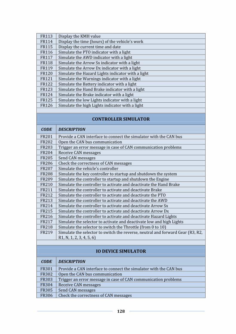
128
FR113 Display the KMH value FR114 Display the time (hours) of the vehicle's work FR115 Display the current time and date FR116 Simulate the PTO indicator with a light FR117 Simulate the AWD indicator with a light FR118 Simulate the Arrow Sx indicator with a light FR119 Simulate the Arrow Dx indicator with a light FR120 Simulate the Hazard Lights indicator with a light FR121 Simulate the Warnings indicator with a light FR122 Simulate the Battery indicator with a light FR123 Simulate the Hand Brake indicator with a light FR124 Simulate the Brake indicator with a light FR125 Simulate the low Lights indicator with a light FR126 Simulate the high Lights indicator with a light
CONTROLLER SIMULATOR
CODE DESCRIPTION
FR201 Provide a CAN interface to connect the simulator with the CAN bus FR202 Open the CAN bus communication FR203 Trigger an error message in case of CAN communication problems FR204 Receive CAN messages FR205 Send CAN messages FR206 Check the correctness of CAN messages FR207 Simulate the vehicle’s controller FR208 Simulate the key controller to startup and shutdown the system FR209 Simulate the controller to startup and shutdown the Engine FR210 Simulate the controller to activate and deactivate the Hand Brake FR211 Simulate the controller to activate and deactivate Brake FR212 Simulate the controller to activate and deactivate the PTO FR213 Simulate the controller to activate and deactivate the AWD FR214 Simulate the controller to activate and deactivate Arrow Sx FR215 Simulate the controller to activate and deactivate Arrow Dx FR216 Simulate the controller to activate and deactivate Hazard Lights FR217 Simulate the selector to activate and deactivate low and high Lights FR218 Simulate the selector to switch the Throttle (from 0 to 10) FR219 Simulate the selector to switch the reverse, neutral and forward Gear (R3, R2,
R1, N, 1, 2, 3, 4, 5, 6)
IO DEVICE SIMULATOR
CODE DESCRIPTION
FR301 Provide a CAN interface to connect the simulator with the CAN bus FR302 Open the CAN bus communication FR303 Trigger an error message in case of CAN communication problems FR304 Receive CAN messages FR305 Send CAN messages FR306 Check the correctness of CAN messages

129
FR307 Provide an IO signal interface to connect the simulator with IO signals FR308 Open the IO communication FR309 Trigger an error message in case of IO communication problems FR310 Read IO signals FR311 Write IO signals FR312 Receive key CAN messages and write information on the key output signal FR313 Receive Engine CAN messages and write information on the Engine output
signal FR314 Receive Hand Brake CAN messages and write information on the Hand Brake
output signal
FR315 Receive Brake CAN messages and write information on the Brake output signal
FR316 Receive PTO CAN messages and write information on the PTO output signal FR317 Receive AWD CAN messages and write information on the AWD output signal
FR318 Receive Arrow Sx CAN messages and write information on the Arrow Sx output signal
FR319 Receive Arrow Dx CAN messages and write information on the Arrow Dx output signal
FR320 Receive Hazard Lights CAN messages and write information on the Hazard Lights output signal
FR321 Receive Lights messages CAN and write information on the Lights output signal
FR322 Receive Throttle messages CAN and write information on the Throttle output signal
FR323 Receive Gear messages CAN and write information on the Gear output signal FR324 Receive Fan messages CAN and write information on the Fan output signal
FR325 Read the water temperature input signal and send information on the CAN bus
FR326 Read the Fuel Level input signal and send information on the CAN bus FR327 Read the RPM input signal and send information on the CAN bus FR328 Read the KMH input signal and send information on the CAN bus FR329 Read the Battery Level input signal and send information on the CAN bus
VEHICLE SIMULATOR
CODE DESCRIPTION
FR401 Simulate the Key indicator with a light FR402 Simulate the Engine indicator with a light FR403 Simulate the Fan indicator with a light FR404 Simulate the PTO indicator with a light FR405 Simulate the AWD indicator with a light FR406 Simulate Arrow Sx indicator with lights FR407 Simulate Arrow Dx indicator with light FR408 Simulate Hazard Lights indicator with a light FR409 Simulate the Hand Brake indicator with a light FR410 Simulate the Brake indicator with a light FR411 Represents the hand brake and brake with the same indicator FR412 Simulate the low Lights indicator with a light FR413 Simulate the high Lights indicator with a light
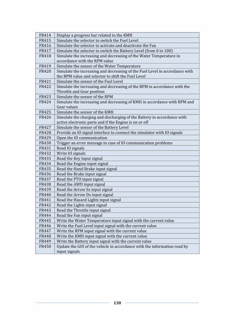
130
FR414 Display a progress bar related to the KMH FR415 Simulate the selector to switch the Fuel Level FR416 Simulate the selector to activate and deactivate the Fan FR417 Simulate the selector to switch the Battery Level (from 0 to 100) FR418 Simulate the increasing and decreasing of the Water Temperature in
accordance with the RPM value FR419 Simulate the sensor of the Water Temperature FR420 Simulate the increasing and decreasing of the Fuel Level in accordance with
the RPM value and selector to shift the Fuel Level FR421 Simulate the sensor of the Fuel Level FR422 Simulate the increasing and decreasing of the RPM in accordance with the
Throttle and Gear position FR423 Simulate the sensor of the RPM FR424 Simulate the increasing and decreasing of KMH in accordance with RPM and
Gear values FR425 Simulate the sensor of the KMH FR426 Simulate the charging and discharging of the Battery in accordance with
active electronic parts and if the Engine is on or off FR427 Simulate the sensor of the Battery Level FR428 Provide an IO signal interface to connect the simulator with IO signals FR429 Open the IO communication FR430 Trigger an error message in case of IO communication problems FR431 Read IO signals FR432 Write IO signals FR433 Read the Key input signal FR434 Read the Engine input signal FR435 Read the Hand Brake input signal FR436 Read the Brake input signal FR437 Read the PTO input signal FR438 Read the AWD input signal FR439 Read the Arrow Sx input signal FR440 Read the Arrow Dx input signal FR441 Read the Hazard Lights input signal FR442 Read the Lights input signal FR443 Read the Throttle input signal FR444 Read the Fan input signal FR445 Write the Water Temperature input signal with the current value FR446 Write the Fuel Level input signal with the current value FR447 Write the RPM input signal with the current value FR448 Write the KMH input signal with the current value FR449 Write the Battery input signal with the current value FR450 Update the GUI of the vehicle in accordance with the information read by
input signals