system manual - sma energy system home with sunny boy
TRANSCRIPT

System Manual
SMA ENERGY SYSTEM HOME withSUNNY BOY STORAGE 3.8-US / 5.0-US / 6.0-US
SBSUL9540-SH-en-11 | Version 1.1ENGLISH
Legal Provisions SMA Solar Technology AG
System ManualSBSUL9540-SH-en-112
Legal ProvisionsThe information contained in these documents is the property of SMA Solar Technology AG. No part of this documentmay be reproduced, stored in a retrieval system, or transmitted, in any form or by any means, be it electronic,mechanical, photographic, magnetic or otherwise, without the prior written permission of SMA Solar Technology AG.Internal reproduction used solely for the purpose of product evaluation or other proper use is allowed and does notrequire prior approval.SMA Solar Technology AG makes no representations or warranties, express or implied, with respect to thisdocumentation or any of the equipment and/or software it may describe, including (with no limitation) any impliedwarranties of utility, merchantability, or fitness for any particular purpose. All such representations or warranties areexpressly disclaimed. Neither SMA Solar Technology AG nor its distributors or dealers shall be liable for any indirect,incidental, or consequential damages under any circumstances.The exclusion of implied warranties may not apply in all cases under some statutes, and thus the above exclusion maynot apply.Specifications are subject to change without notice. Every attempt has been made to make this document complete,accurate and up-to-date. Readers are cautioned, however, that product improvements and field usage experience maycause SMA Solar Technology AG to make changes to these specifications without advance notice or per contractprovisions. SMA Solar Technology AG shall not be responsible for any damages, including indirect, incidental orconsequential damages, caused by reliance on the material presented, including, but not limited to, omissions,typographical errors, arithmetical errors or listing errors in the content material.
SMA WarrantyYou can download the current warranty conditions from the Internet at www.SMA-Solar.com.
TrademarksAll trademarks are recognized, even if not explicitly identified as such. Missing designations do not mean that aproduct or brand is not a registered trademark.
SMA Solar Technology AGSonnenallee 134266 NiestetalGermanyPhone +49 561 9522-0Fax +49 561 9522 100www.SMA.deE-mail: [email protected]: 11/1/2021Copyright © 2021 SMA Solar Technology AG. All rights reserved.
1 Information on this DocumentSMA Solar Technology AG
System Manual 3SBSUL9540-SH-en-11
1 Information on this Document1.1 ValidityThis document is valid for:
SMA Energy Systems with the Sunny Boy Storage 3.8-US / 5.0-US / 6.0-US from firmware version >3.00.##.RSMA
• SMA-ESS-SBS3.8-RESU10H• SMA-ESS-SBS5.0-RESU10H• SMA-ESS-SBS6.0-RESU10H
• SMA-ESS-SBS3.8-RESU16HPRIME• SMA-ESS-SBS5.0-RESU16HPRIME• SMA-ESS-SBS6.0-RESU16HPRIME
• SMA-ESS-SBS3.8-BYDH5.0• SMA-ESS-SBS5.0-BYDH5.0• SMA-ESS-SBS6.0-BYDH5.0
• SMA-ESS-SBS3.8-BYDH7.5• SMA-ESS-SBS5.0-BYDH7.5• SMA-ESS-SBS6.0-BYDH7.5
• SMA-ESS-SBS3.8-BYDH10.0• SMA-ESS-SBS5.0-BYDH10.0• SMA-ESS-SBS6.0-BYDH10.0
• SMA-ESS-SBS3.8-BYDHVL12.0• SMA-ESS-SBS5.0-BYDHVL12.0• SMA-ESS-SBS6.0-BYDHVL12.0
• SMA-ESS-SBS3.8-BYDHVL16.0• SMA-ESS-SBS5.0-BYDHVL16.0• SMA-ESS-SBS6.0-BYDHVL16.0
• SMA-ESS-SBS3.8-BYDHVL20.0• SMA-ESS-SBS5.0-BYDHVL20.0• SMA-ESS-SBS6.0-BYDHVL20.0
• SMA-ESS-SBS3.8-BYDHVL24.0• SMA-ESS-SBS5.0-BYDHVL24.0• SMA-ESS-SBS6.0-BYDHVL24.0
• SMA-ESS-SBS3.8-BYDHVL28.0• SMA-ESS-SBS5.0-BYDHVL28.0• SMA-ESS-SBS6.0-BYDHVL28.0
• SMA-ESS-SBS3.8-BYDHVL32.0• SMA-ESS-SBS5.0-BYDHVL32.0• SMA-ESS-SBS6.0-BYDHVL32.0
1.2 Target GroupThe tasks described in this document must only be performed by qualified persons. Qualified persons must have thefollowing skills:
• Knowledge of how an inverter works and is operated• Knowledge of how batteries work and are operated• Training in how to deal with the dangers and risks associated with installing, repairing and using electrical
devices, batteries and installations• Training in the installation and commissioning of electrical devices and installations• Knowledge of all applicable laws, standards and directives• Knowledge of and compliance with this document and all safety information• Knowledge of and compliance with the documents of the battery manufacturer with all safety information
1.3 Content and Structure of this DocumentThis document summarizes the specific information for the system and describes the procedure for installation andcommissioning.

1 Information on this Document SMA Solar Technology AG
System ManualSBSUL9540-SH-en-114
Circuitry overviews provide the basic principle of how a system must be set up and connected.The latest version of this document and the comprehensive manual for installation, commissioning, configuration anddecommissioning of each SMA product can be found in PDF format or as eManual at www.SMA-Solar.com.The latest version of the battery documentation can be found on the website of the battery manufacturer.The latest version of the documentation of the WattNode Modbus energy meter can be found at www.ctlsys.com.This document supplements the documents that are enclosed with each product and does not replace any locallyapplicable codes or standards. Read and observe all documents supplied with the product.Illustrations in this document are reduced to the essential information and may deviate from the real product.
1.4 Levels of warning messagesThe following levels of warning messages may occur when handling the product.
DANGER
Indicates a hazardous situation which, if not avoided, will result in death or serious injury.
WARNING
Indicates a hazardous situation which, if not avoided, could result in death or serious injury.
CAUTION
Indicates a hazardous situation which, if not avoided, could result in minor or moderate injury.
NOTICE
Indicates a situation which, if not avoided, can result in property damage.
1.5 Symbols in the DocumentIcon Explanation
Information that is important for a specific topic or goal, but is not safety-relevant
☐ Indicates a requirement for meeting a specific goal
☑ Desired result
✖ A problem that might occur.
Example
1.6 Typographical Elements in the DocumentTypographical element Use Example
bold • Messages• Terminals• Elements on a user interface• Elements to be selected• Elements to be entered
• Connect the insulated conductorsto the terminals X703:1 toX703:6.
• Enter 10 in the field Minutes.
1 Information on this DocumentSMA Solar Technology AG
System Manual 5SBSUL9540-SH-en-11
Typographical element Use Example
> • Connects several elements to beselected
• Go to Settings > Date.
[Button][Key]
• Button or key to be clicked on orpressed down
• Select [Enter].
# • Placeholder for variable components(e.g., parameter names)
• Parameter WCtlHz.Hz#
1.7 Additional InformationFor more information, please go to www.SMA-Solar.com.
Title and information content Type of information Hyperlink and QR-Code
SUNNY BOY STORAGE 3.8-US / 5.0-US /6.0-US
Installation manual SBSxx-US-10-IA-xx-12.pdf
SUNNY BOY STORAGE 3.8-US / 5.0-US /6.0-US
User Manual SBSxx-US-10-BA-en-11.pdfhttps://manuals.sma.de/SBSxx-US-10/en-US/index.html
"Approved batteries and battery communica-tion connection"Overview of approved batteries and circuitryoverview of the battery communication connec-tion
Technical Information SBS-Batteries-TI-en.pdf
1 Information on this Document SMA Solar Technology AG
System ManualSBSUL9540-SH-en-116
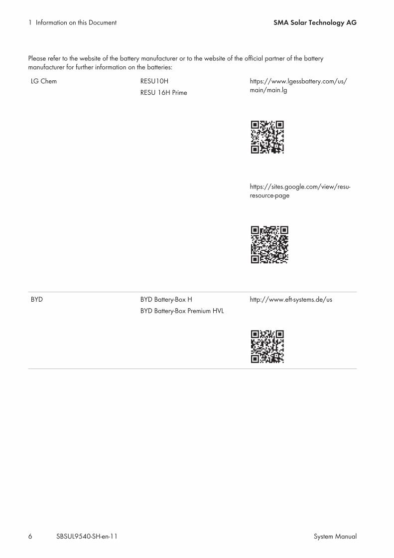
Please refer to the website of the battery manufacturer or to the website of the official partner of the batterymanufacturer for further information on the batteries:
LG Chem RESU10HRESU 16H Prime
https://www.lgessbattery.com/us/main/main.lg
https://sites.google.com/view/resu-resource-page
BYD BYD Battery-Box HBYD Battery-Box Premium HVL
http://www.eft-systems.de/us
2 SafetySMA Solar Technology AG
System Manual 7SBSUL9540-SH-en-11
2 Safety2.1 Intended UseThe SMA Energy System is a storage system and optimizes self-consumption of PV energy and lowers the energyobtained from the utility grid by the following measures:
• Intermediate storage of PV energy in the battery• Data logging at the grid-connection point with the energy meter (Modbus RTU)• Visualization of the consumption and generation data from your system in Sunny Portal
Impairment of system communicationThe use of external, unapproved components can affect the system communication.
• Only use approved components in the system.
Grid feed-in and purchased energy (from the utility grid) are only recorded with the energy meter (Modbus RTU). Theenergy meter (Modbus RTU) does not replace the energy meter of the electric utility company.Use SMA products only in accordance with the information provided in the enclosed documentation and with thelocally applicable laws, regulations, standards and directives. Any other application may cause personal injury orproperty damage.
2.2 IMPORTANT SAFETY INSTRUCTIONSKeep the manual for future reference.This section contains safety information that must be observed at all times when working.
DANGER
Danger of fatal electric shock due to non-compliance with the safety instructions in thedocuments that are enclosed with each product.This document supplements the documents that are enclosed with each product and does not replace any locallyapplicable codes or standards.
• Read and observe all documents enclosed with the products.
If the AC connection of the inverter is disconnected and the battery is switched off, there is norisk of electric arcs during installation or servicing.If the AC circuit breakers of the inverters are switched off and secured against reconnection and the battery or theload-break switch of the battery is turned off and secured against reconnection, there is no danger of an electricarc during installation or servicing. Be aware that, when using batteries from BYD, the individual battery modulesdo not have their own disconnects. With BYD batteries, all modules are disconnected by means of the main switchof the Battery Control Unit (BCU - top section). The AC circuit breaker of the inverter must be installed in thedistribution board.
3 System Components SMA Solar Technology AG
System ManualSBSUL9540-SH-en-118
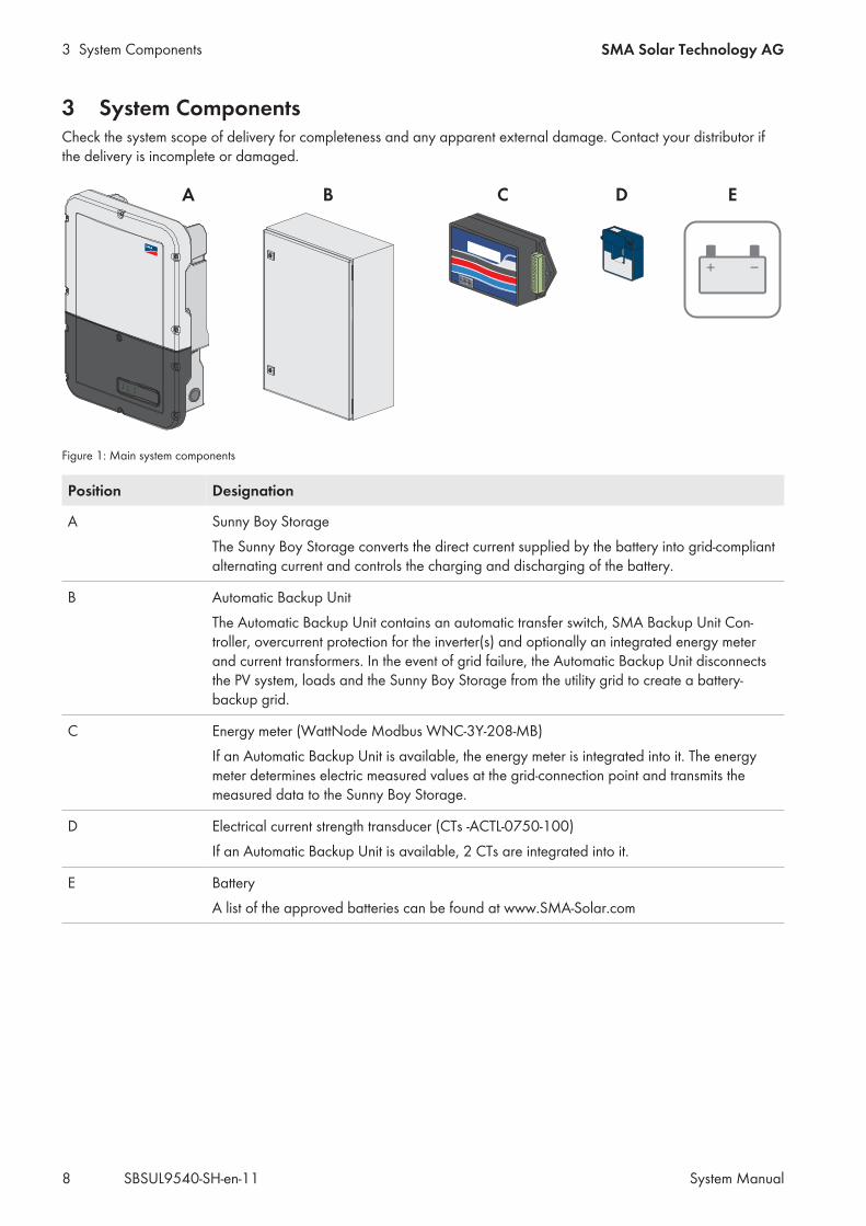
3 System ComponentsCheck the system scope of delivery for completeness and any apparent external damage. Contact your distributor ifthe delivery is incomplete or damaged.
B CA ED
Figure 1: Main system components
Position Designation
A Sunny Boy StorageThe Sunny Boy Storage converts the direct current supplied by the battery into grid-compliantalternating current and controls the charging and discharging of the battery.
B Automatic Backup UnitThe Automatic Backup Unit contains an automatic transfer switch, SMA Backup Unit Con-troller, overcurrent protection for the inverter(s) and optionally an integrated energy meterand current transformers. In the event of grid failure, the Automatic Backup Unit disconnectsthe PV system, loads and the Sunny Boy Storage from the utility grid to create a battery-backup grid.
C Energy meter (WattNode Modbus WNC-3Y-208-MB)If an Automatic Backup Unit is available, the energy meter is integrated into it. The energymeter determines electric measured values at the grid-connection point and transmits themeasured data to the Sunny Boy Storage.
D Electrical current strength transducer (CTs -ACTL-0750-100)If an Automatic Backup Unit is available, 2 CTs are integrated into it.
E BatteryA list of the approved batteries can be found at www.SMA-Solar.com
4 Circuitry OverviewSMA Solar Technology AG
System Manual 9SBSUL9540-SH-en-11
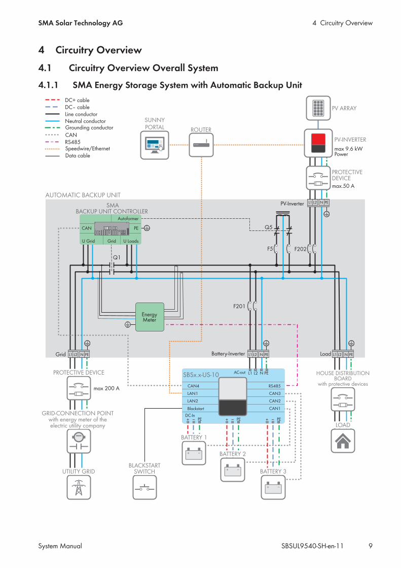
4 Circuitry Overview4.1 Circuitry Overview Overall System
4.1.1 SMA Energy Storage System with Automatic Backup Unit
SUNNYPORTAL
SMABACKUP UNIT CONTROLLER
Q1
L1 N PEL2
F201
F5
Q5
F202
U Grid
CAN
Grid U Loads
PE
Autoformer
DC-In
N
LAN1
CAN1Blackstart
AC-out L1 PE
CAN2
CAN4
CAN3
LAN2
+ _ PE + _ PE + _ PE
RS485
L2SBSx.x-US-10
EnergyMeter
L1 N PEL2L1 N PEL2
L1 N PEL2
AUTOMATIC BACKUP UNIT
BATTERY 1
BATTERY 2
BATTERY 3
max 9.6 kWPower
max.50 A
PV-Inverter
max 200 A
LoadBattery-InverterGrid
Data cable
Grounding conductor
CAN
Line conductor
DC+ cableDC– cable
Speedwire/EthernetRS485
Neutral conductor
BLACKSTARTSWITCH
GRID-CONNECTION POINTwith energy meter of theelectric utility company
PROTECTIVE DEVICE
UTILITY GRID
HOUSE DISTRIBUTIONBOARD
with protective devices
PROTECTIVEDEVICE
PV-INVERTER
PV ARRAY
ROUTER
LOAD
4 Circuitry Overview SMA Solar Technology AG
System ManualSBSUL9540-SH-en-1110
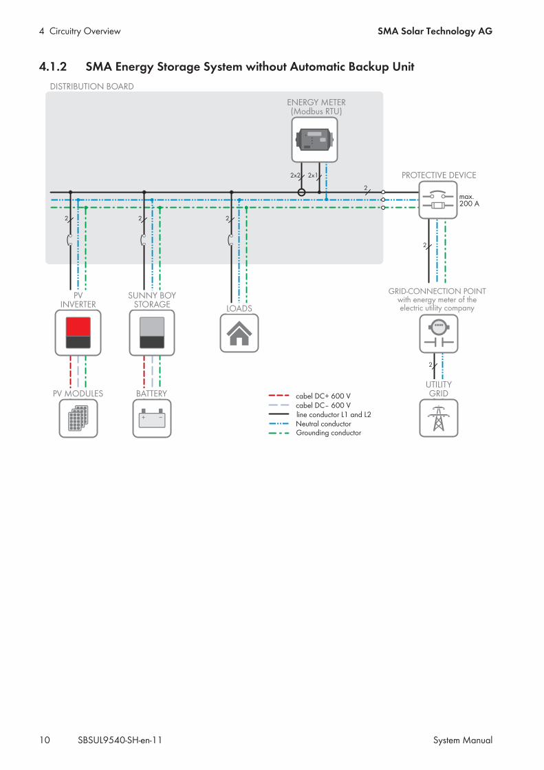
4.1.2 SMA Energy Storage System without Automatic Backup Unit
SUNNY BOYSTORAGE
max.200 A
PROTECTIVE DEVICE2x2 2x1
2 22
2
2
2
ENERGY METER(Modbus RTU)
Grounding conductor
line conductor L1 and L2Neutral conductor
cabel DC+ 600 Vcabel DC– 600 V
LOADS
PV MODULES
DISTRIBUTION BOARD
GRID-CONNECTION POINTwith energy meter of theelectric utility company
UTILITYGRIDBATTERY
PVINVERTER
4 Circuitry OverviewSMA Solar Technology AG
System Manual 11SBSUL9540-SH-en-11
4.2 Circuitry Overview Battery Communication Connection
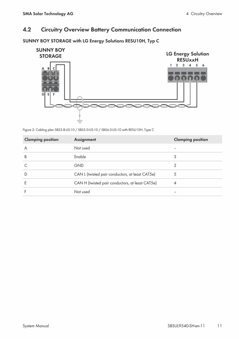
SUNNY BOY STORAGE with LG Energy Solutions RESU10H, Typ C
1
SUNNY BOYSTORAGE
65432A B C
D E F
LG Energy SolutionRESUxxH
Figure 2: Cabling plan SBS3.8-US-10 / SBS5.0-US-10 / SBS6.0-US-10 with RESU10H, Type C
Clamping position Assignment Clamping position
A Not used ‒
B Enable 3
C GND 2
D CAN L (twisted pair conductors, at least CAT5e) 5
E CAN H (twisted pair conductors, at least CAT5e) 4
F Not used ‒
4 Circuitry Overview SMA Solar Technology AG
System ManualSBSUL9540-SH-en-1112
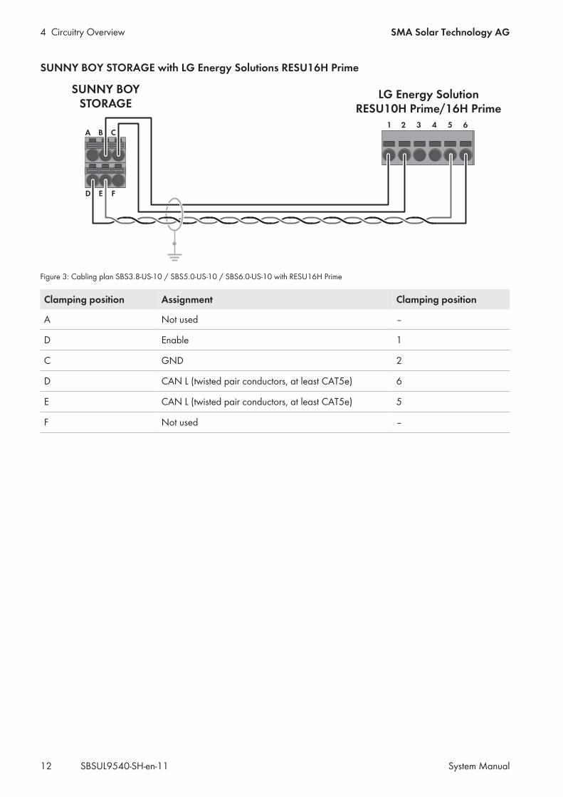
SUNNY BOY STORAGE with LG Energy Solutions RESU16H Prime
1
SUNNY BOYSTORAGE
65432A B C
D E F
LG Energy SolutionRESU10H Prime/16H Prime
Figure 3: Cabling plan SBS3.8-US-10 / SBS5.0-US-10 / SBS6.0-US-10 with RESU16H Prime
Clamping position Assignment Clamping position
A Not used ‒
D Enable 1
C GND 2
D CAN L (twisted pair conductors, at least CAT5e) 6
E CAN L (twisted pair conductors, at least CAT5e) 5
F Not used ‒
4 Circuitry OverviewSMA Solar Technology AG
System Manual 13SBSUL9540-SH-en-11
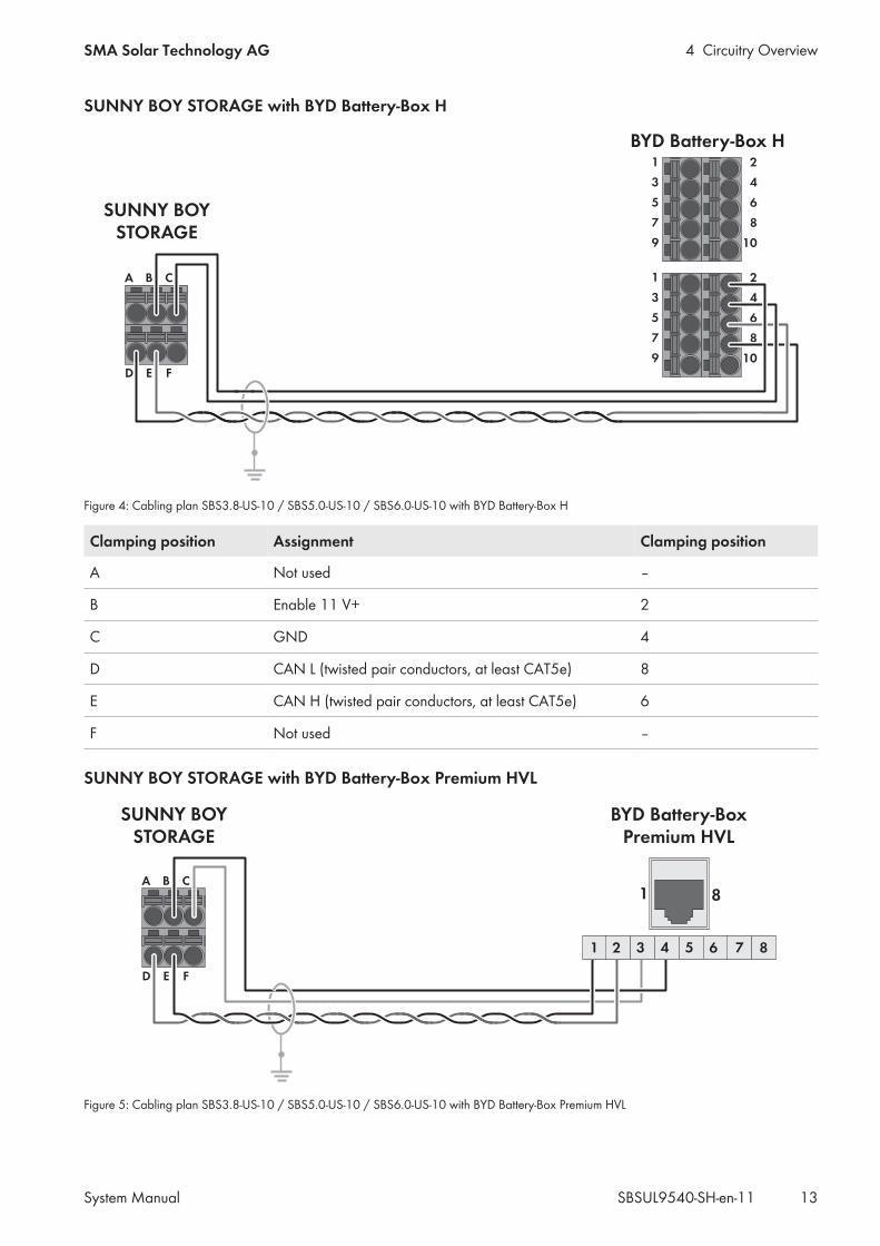
SUNNY BOY STORAGE with BYD Battery-Box H
1
3
5
7
9
SUNNY BOYSTORAGE
A B C
D E F
2
4
6
8
10
BYD Battery-Box H1
3
5
7
9
2
4
6
8
10
Figure 4: Cabling plan SBS3.8-US-10 / SBS5.0-US-10 / SBS6.0-US-10 with BYD Battery-Box H
Clamping position Assignment Clamping position
A Not used ‒
B Enable 11 V+ 2
C GND 4
D CAN L (twisted pair conductors, at least CAT5e) 8
E CAN H (twisted pair conductors, at least CAT5e) 6
F Not used ‒
SUNNY BOY STORAGE with BYD Battery-Box Premium HVL
SUNNY BOYSTORAGE
A B C
D E F
BYD Battery-BoxPremium HVL
1 65432 87
81
Figure 5: Cabling plan SBS3.8-US-10 / SBS5.0-US-10 / SBS6.0-US-10 with BYD Battery-Box Premium HVL

4 Circuitry Overview SMA Solar Technology AG
System ManualSBSUL9540-SH-en-1114
Clamping position Assignment Pin
A Not used -
B Enable 4
C GND 3
D CAN L (twisted pair conductors, at least CAT5e) 2
E CAN L (twisted pair conductors, at least CAT5e) 1
F Not used -

5 InstallationSMA Solar Technology AG
System Manual 15SBSUL9540-SH-en-11
5 Installation5.1 Requirements for the InstallationRequirements for the Mounting Location:
WARNING
Danger to life due to fire or explosionDespite careful construction, electrical devices can cause fires. This can result in death or serious injury.
• Do not mount the product in areas containing highly flammable materials or gases.• Do not mount the product in potentially explosive atmospheres.
Requirements in the documents enclosed with each product must be observed.This document supplements the documents that are enclosed with each product and does not replace any locallyapplicable codes or standards.
• Read and observe the requirements in the documents enclosed with the products in addition to therequirements stated below.
☐ The system may be installed outdoors. The system components must not be exposed to direct solar irradiation andmust be protected from rain water. When becoming too hot, the system reduces its power output to avoidoverheating.
☐ The system must not be installed in earthquake-prone areas.☐ The system must not be installed in coastal areas where salt spray is possible.☐ A solid support surface must be available (e.g. concrete, masonry or wood). When mounted on support surfaces
that are not solid, the product can emit audible vibrations during operation which could be perceived asannoying.
☐ The mounting location must be suitable for the weight and dimensions of the system components (see technicaldata in the enclosed manuals of the individual components)
☐ The mounting location should be freely and safely accessible at all times without the need for any auxiliaryequipment (such as scaffolding or lifting platforms). Non-fulfillment of these criteria may restrict servicing.
☐ To ensure optimal operation of the system, the ambient temperature must be between -10 and +45 °C (-14 °F to113°F).
Additionally required material (not included in the scope of delivery):☐ Electrical distribution board (EDP or MSP) with required electric equipment☐ One router for the connection to the Internet SMA Solar Technology AG (Internet flat rate recommended).☐ One switch for connection of multiple Ethernet cables.☐ Network cable(s)☐ Battery data cable(s)
Switch requirements:☐ At least 5 Ethernet connections must be available☐ The switch must be permeable for broad and multicasts☐ Do not use an IGMP Snooping Switch as per RFC 4541
Router requirements:☐ DHCP should be supported (if possible with MAC address binding). If DHCP is not supported, an IP address from
the address range of the router must be assigned manually to each device.
5 Installation SMA Solar Technology AG
System ManualSBSUL9540-SH-en-1116
☐ TCP ports 123, 443 and 9524 must be authorized for outgoing connections.☐ Fast Ethernet with 100 Mbit/s data transfer rate☐ IGMP protocol version 2 or version 3 (IGMPv2 or IGMPv3) must be supported.☐ The IPv4 protocol must be used at least in the internal network. The IPv6 protocol may be active in parallel.
Network cable requirements:The cable length and quality affect the quality of the signal. Observe the following cable requirements:☐ Cable type: 100BaseTx☐ Cable category: minimum CAT5e☐ Plug type: RJ45 of Cat5, Cat5e or higher☐ Shielding: SF/UTP, S/UTP, SF/FTP or S/FTP☐ Number of insulated conductor pairs and insulated conductor cross-section: at least 2 x 2 x 0.22 mm² (2 x 2 x
24 AWG)☐ Maximum cable length between 2 nodes when using patch cables: 50 m (164 ft)☐ Maximum cable length between 2 nodes when using installation cables: 100 m (328 ft)☐ UV-resistant for outdoor use.
Network cable (SBS to switch, battery to switch) requirements:☐ Twisted pair conductors☐ Cable category: minimum CAT5e☐ Cable with shielding: Yes☐ Conductor cross-section: 0.25 mm² to 0.34 mm² (24 AWG to 16 AWG)☐ Recommended number of conductor pairs: 4☐ External diameter: 6 mm to 8.5 mm (0.24 in to 0.33 in)☐ Maximum cable length between a battery and the inverter: 10 m (33 ft)☐ If the cables are routed together with the DC conductors in a conduit, each cable has to be insulated for 600 V.☐ UV-resistant for outdoor use.☐ Comply with the requirements of the battery manufacturer.
Requirements for energy meter communication cable:☐ Cross-section: at least 2 x 2 x 0.22 mm² (2 x 2 x 24 AWG)☐ Shielding: yes☐ Twisted pair conductors☐ UV-resistant for outdoor use.☐ Maximum cable length: 10 m (33 ft)
Requirements:☐ The electrical distribution board (EDP) is installed.☐ The router is installed.☐ The switch is installed.
5.2 Installation ProcedureThis section describes the procedure for the installation and gives an overview of the steps, which must always beperformed in the prescribed sequence.
5 InstallationSMA Solar Technology AG
System Manual 17SBSUL9540-SH-en-11
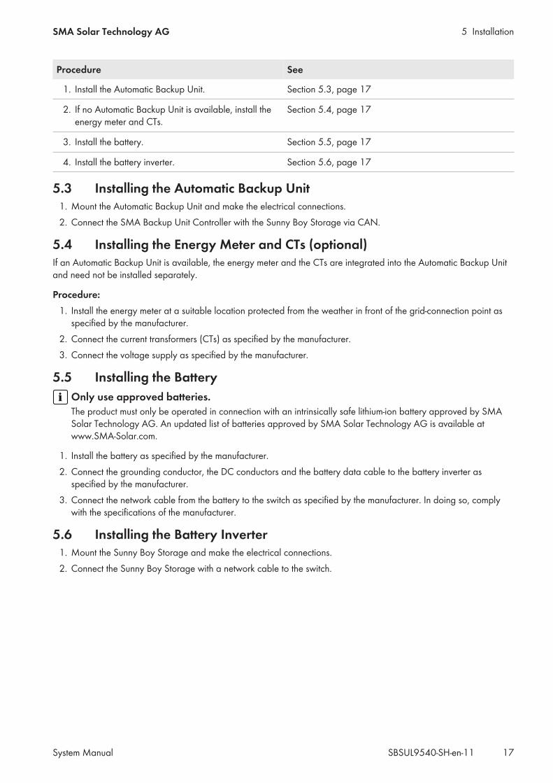
Procedure See
1. Install the Automatic Backup Unit. Section 5.3, page 17
2. If no Automatic Backup Unit is available, install theenergy meter and CTs.
Section 5.4, page 17
3. Install the battery. Section 5.5, page 17
4. Install the battery inverter. Section 5.6, page 17
5.3 Installing the Automatic Backup Unit1. Mount the Automatic Backup Unit and make the electrical connections.2. Connect the SMA Backup Unit Controller with the Sunny Boy Storage via CAN.
5.4 Installing the Energy Meter and CTs (optional)If an Automatic Backup Unit is available, the energy meter and the CTs are integrated into the Automatic Backup Unitand need not be installed separately.
Procedure:1. Install the energy meter at a suitable location protected from the weather in front of the grid-connection point as
specified by the manufacturer.2. Connect the current transformers (CTs) as specified by the manufacturer.3. Connect the voltage supply as specified by the manufacturer.
5.5 Installing the BatteryOnly use approved batteries.The product must only be operated in connection with an intrinsically safe lithium-ion battery approved by SMASolar Technology AG. An updated list of batteries approved by SMA Solar Technology AG is available atwww.SMA-Solar.com.
1. Install the battery as specified by the manufacturer.2. Connect the grounding conductor, the DC conductors and the battery data cable to the battery inverter as
specified by the manufacturer.3. Connect the network cable from the battery to the switch as specified by the manufacturer. In doing so, comply
with the specifications of the manufacturer.
5.6 Installing the Battery Inverter1. Mount the Sunny Boy Storage and make the electrical connections.2. Connect the Sunny Boy Storage with a network cable to the switch.

6 Commissioning SMA Solar Technology AG
System ManualSBSUL9540-SH-en-1118
6 Commissioning6.1 Commissioning ProcedureThis section describes the commissioning procedure and gives an overview of the steps you must always perform in theprescribed order.
Procedure See
1. Commission the battery. Section 6.2, page 18
2. Commission and configure the battery inverter. Section 6.3, page 18
3. Set the time-of-use (optional). Section 6.3.4, page 20
4. Set the Peak Load Shaving function (optional). Section 6.3.5, page 20
5. Register system in Sunny Portal. Section 6.4, page 21
6.2 Commissioning the Battery1. Switch on the battery.2. Configure the battery as specified by the manufacturer.
6.3 Commissioning and Configuring the Battery Inverter
6.3.1 Commissioning the Battery Inverter• Switch on the AC circuit breaker.☑ All three LEDs light up. The start-up phase begins. All three LEDs go out again after approximately 90 seconds.☑ Depending on the available power, the green LED pulses or is continuously illuminated. The inverter is feeding in.
6.3.2 Establishing a Connection to the User Interface of the Battery InverterSSID, IP address and WLAN password
• SSID in WLAN: SMA[serial number] (e.g. SMA0123456789)• Device-specific WLAN password: see WPA2-PSK on the type label of the product or the rear side of the
manual included in delivery• Standard access address for a direct connection via WLAN outside of a local network: https://
smalogin.net or 192.168.12.3
Using serial number of inverter for connecting to user interfaceThe inverter serial number is on the supplementary type label. PIC and RID for registration in the Sunny Portal arealso included there. The supplementary type label is attached to the Connection Unit.
• Use serial number on supplementary type label for connecting to user interface.
Requirements:☐ An end device (e.g. computer, tablet PC or smartphone) must be available.☐ The respective latest version of one of the following web browsers must be installed: Chrome, Edge, Firefox or
Safari.☐ JavaScript must be enabled in the web browser of the end device.☐ The installer's SMA Grid Guard code must be available to change network-relevant settings after the first 10 hours
of feed-in operation, or after completing the installation assistant. You can request the SMA Grid Guard code viathe Online Service Center.
6 CommissioningSMA Solar Technology AG
System Manual 19SBSUL9540-SH-en-11
Procedure:1. If your end device has a WPS function:
• Activate the WPS function on the inverter. To do this, tap twice on the enclosure lid of the Connection Unit.☑ The blue LED flashes quickly for two minutes.
• Activate the WPS on your end device.☑ The connection with your end device will be established automatically. It can take up to 20 seconds for
this connection to be established.2. If your end device does not have a WPS function:
• Search for Wi-Fi networks with your end device.• Select the SSID of the inverter SMA[serial number] in the list with the found WLAN networks.• Enter the device-specific Wi-Fi password (see WPA2-PSK on the type label of the product or the rear side of
the manual included in delivery).• Open the web browser of your end device and enter https://smalogin.net in the address bar.
☑ The login page of the user interface opens.• If the login page of the user interface does not open, enter the IP address 192.168.12.3 or, if your end
device supports mDNS services, SMA[serial number].local or https://SMA[serial number] in theaddress bar of the web browser.
6.3.3 Configuring the Battery Inverter Using the Installation AssistantPassword assignmentAll SMA devices in the system need the same password for the Installer user group. The password is then usedas the system password and applies to all devices in the system. For the registration of the system in Sunny Portal,it is essential that all SMA devices have the same password.
• Assign a password to all SMA devices in the system.
Procedure:1. Log into the user interface as an Installer. Assign a new password.2. Select the configuration option Configuration with Installation Assistant.
☑ The installation assistant will open.3. Make the network configuration or apply the automatic configuration and select [Save and next].4. Set the Automatic time synchronization to [On] and in the drop-down list Time zone select the desired time
zone.5. Select [Save and next].6. In the drop-down list Set country standard select the desired country standard and then [Save and next].7. In the step Meter configuration, select Wattnode Modbus RTU from the Used energy meter drop-down list.8. Select [Save and next].9. Grid management service configuration:
• From the drop-down list Connected line conductors, select the line conductor to which the battery inverteris connected.
• Set Feed-in management at the grid-connection point to [Off].• Select [Save and next].
10. In the step Configuration battery/battery-backup system, check if the connected battery has been detectedand the correct battery type and serial number are listed in the overview Detected battery types and if a greencheck mark appears in the overview Status.
6 Commissioning SMA Solar Technology AG
System ManualSBSUL9540-SH-en-1120
11. Select [Save and next].12. Check all settings in the summary. You can export the summary or all parameters. Once all settings are correct,
select [Next]. The configuration of the Sunny Boy Storage is now complete.
6.3.4 Set the Time-of-Use (optional)
Time-of-UseThe Time-of-Use (TOU) function is disabled by default and must be enabled by creating power profiles.With the TOU function, you can adjust the charging behavior of the battery to your utility rate plan (electricity tariff).Energy bills are thus reduced and electricity at lower cost can be used. You can determine in which time range thebattery with a specified charging power is operated. At specific times, this is mostly useful when the battery's state ofcharge has to take on a certain value or the rate plan makes the charging more attractive, regardless of the power atthe grid connection point. The charging parameters set in the power profile are only limited by the state of charge(SOC). At times when the Time-of-Use function is not enabled, the battery is charged correspondent to the increasedself-consumption for the entire system.
Procedure:1. Activate the battery inverter user interface.2. Log in as Installer.3. Select the menu User settings.4. Select [Power profile].5. Select the button [Active].6. Select the icon Create new power profile.7. Enter the name of the power profile in the field Name of the power profile.8. Select the entry Time of use in the drop-down list Operating mode of the power profile.9. Enter the target charging power in the field Forced charging power. The power is set independently of the grid-
connection point.10. Make the time range setting. You can select on which days of the week, in which date range and at what time the
power profile should be valid. Even a power profile independent of the days of the week, which should be validon a set date, can be configured. For this, you must select the the option Independent of days of the week.
11. To temporarily save the power profile and to possibly create other power profiles, select the 'save' icon to the rightof the overview Created power profiles. The data are saved temporarily on this page. The data are onlytransferred when the page is closed by clicking on the [Save] button.
12. To assign priority to multiple power profiles, select the desired power profile in the overview Created powerprofiles and set the priority by moving the power profile up or down.
13. To save the power profile and to close the page, select [Save].14. To deactivate a power profile, select the desired power profile in the overview Created power profiles and
then select the entry Inactive from the drop-down list Operating mode of the power profile.
6.3.5 Setting the Peak Load Shaving Function (optional)
Peak load shavingWith the "Peak Load Shaving" function, you can optimize the behavior of the battery inverter with respect to the powerexchange at the point of interconnection. This is mostly useful when a higher supply of energy would lead to a higherelectricity cost. With the "Peak Load Shaving" function, certain grid-exchange power outputs to which the batteryinverter is adjusted depending on its power and battery capacity available can be set. Power peaks and additionalcosts can thus be avoided.
6 CommissioningSMA Solar Technology AG
System Manual 21SBSUL9540-SH-en-11
You can configure times and setpoints for the power drawn at the grid-connection point. When the loads requireadditional energy, the battery is discharged and the maximum value is kept constant at the grid-connection point. Thisis based on the prerequisite that the battery is sufficiently charged. At times when the "Peak Load Shaving" function isnot activated, the battery is charged or discharged correspondent to the increased self-consumption for the entiresystem. The "Peak Load Shaving" function is deactivated by default and must be activated by creating power profiles.
Procedure:1. Activate the battery inverter user interface.2. Log in as Installer.3. Select the menu User settings.4. Select [Power profile].5. Select the button [Active].6. Select the icon Create new power profile.7. Enter the name of the power profile in the field Name of the power profile.8. Select the entry Peak Load Shaving from the drop-down list Operating mode of the power profile.9. Enter the target feed-in power in the field Limiting value for the grid feed-in. When this value is reached,
charging of the battery with the surplus energy starts.10. Enter the target purchased power in the field Limiting value for the purchased energy (from the utility
grid). When this value is reached, discharging of the battery starts.11. Make the time range setting. You can select on which days of the week, in which date range and at what time the
power profile should be valid. Even a power profile independent of the days of the week, which should be validon a set date, can be configured. For this, you must select the the option Independent of days of the week.
12. To temporarily save the power profile and to possibly create other power profiles, select the 'save' icon to the rightof the overview Created power profiles. The data are saved temporarily on this page. The data are onlytransferred when the page is closed by clicking on the [Save] button.
13. To assign priority to multiple power profiles, select the desired power profile in the overview Created powerprofiles and set the priority by moving the power profile up or down.
14. To save the power profile and to close the page, select [Save].15. To deactivate a power profile, select the desired power profile in the overview Created power profiles and
then select the entry Inactive from the drop-down list Operating mode of the power profile.
6.4 Registering System in Sunny Portal1. Register system in Sunny Portal: https://www.sunnyportal.com/Register2. Carry out the system setup assistant.3. Activate Smart Connected. To do this, select Yes, I would like to participate in the Smart Connected
program with this performance description. in the extended system properties.
7 Contact SMA Solar Technology AG
System ManualSBSUL9540-SH-en-1122
7 ContactIf you have technical problems with our products, please contact the SMA Service Line. The following data is requiredin order to provide you with the necessary assistance:
• Inverters:– Device type– Serial number– Firmware version– Event message– Mounting location and mounting height– Type and number of PV modules– Detailed description of the problem
• Battery:– Type– Firmware version
• Sunny Portal– System name in Sunny Portal– Access data for Sunny Portal
You can find your country's contact information at:
https://go.sma.de/service

www.SMA-Solar.com