sunny beam wireless pv plant monitoring for sma …files.sma.de/dl/1359/sbeam-12-nx2006.pdf ·...
TRANSCRIPT
Sunny BeamWireless PV Plant Monitoringfor SMA Inverters
User Manual Version 2.2 SBeam-12:NX2006TBA-SBEAM


SMA Technologie AG Table of Contents
User Manual SBeam-12:NX2006 Page 3
Table of Contents1 Notes on using these Instructions . . . . . . . . . . .71.1 Target Group . . . . . . . . . . . . . . . . . . . . . . . . . . . . . . . . . . . . . 71.2 Validity . . . . . . . . . . . . . . . . . . . . . . . . . . . . . . . . . . . . . . . . . . 71.3 Symbols used . . . . . . . . . . . . . . . . . . . . . . . . . . . . . . . . . . . . . 7
2 Sunny Beam . . . . . . . . . . . . . . . . . . . . . . . . . . .92.1 Applications . . . . . . . . . . . . . . . . . . . . . . . . . . . . . . . . . . . . . . 92.2 Functions. . . . . . . . . . . . . . . . . . . . . . . . . . . . . . . . . . . . . . . . .102.3 Scope of Delivery . . . . . . . . . . . . . . . . . . . . . . . . . . . . . . . . . .112.4 Accessories . . . . . . . . . . . . . . . . . . . . . . . . . . . . . . . . . . . . . . .122.5 Identifying the Sunny Beam . . . . . . . . . . . . . . . . . . . . . . . . . . .132.5.1 Type Plate . . . . . . . . . . . . . . . . . . . . . . . . . . . . . . . . . . . . .132.5.2 Firmware Version . . . . . . . . . . . . . . . . . . . . . . . . . . . . . . . .13
3 Safety Instructions. . . . . . . . . . . . . . . . . . . . . .15
4 Mounting the Sunny Beam . . . . . . . . . . . . . . .174.1 Tabletop Device . . . . . . . . . . . . . . . . . . . . . . . . . . . . . . . . . . .174.2 Wall Mounting . . . . . . . . . . . . . . . . . . . . . . . . . . . . . . . . . . . .17
5 Installing a Radio Piggy-Back in an Inverter . .195.1 Ways of Installation . . . . . . . . . . . . . . . . . . . . . . . . . . . . . . . . .195.1.1 installation(A): Radio Piggy-Back and Antenna . . . . . . . . . . .205.1.2 Installation(B): Radio Piggy-Back and Antenna . . . . . . . . . . .225.1.3 Installation(C): Antenna, Piggy-Back ex Factory . . . . . . . . . .245.2 DIP switch setting on the Radio Piggy-Back . . . . . . . . . . . . . . . .255.3 Installation of the external Antenna Kit . . . . . . . . . . . . . . . . . . .265.3.1 Retrofitting for initial Situation (A) . . . . . . . . . . . . . . . . . . . .285.3.2 Retrofitting for initial Situation (B). . . . . . . . . . . . . . . . . . . . .325.3.3 Installation for initial Situation (C) . . . . . . . . . . . . . . . . . . . .345.4 Basic Information on Radio Transfer . . . . . . . . . . . . . . . . . . . . .365.4.1 Antenna on Inverter . . . . . . . . . . . . . . . . . . . . . . . . . . . . . .375.4.2 External Antenna Kit . . . . . . . . . . . . . . . . . . . . . . . . . . . . . .38

Table of Contents SMA Technologie AG
Page 4 SBeam-12:NX2006 User Manual
6 Operating the Sunny Beam . . . . . . . . . . . . . . .416.1 Inserting the Batteries. . . . . . . . . . . . . . . . . . . . . . . . . . . . . . . .416.2 Initial Startup. . . . . . . . . . . . . . . . . . . . . . . . . . . . . . . . . . . . . .426.2.1 The Rotating Push Button . . . . . . . . . . . . . . . . . . . . . . . . . . .426.2.2 Initial Settings . . . . . . . . . . . . . . . . . . . . . . . . . . . . . . . . . . .426.3 The display Elements . . . . . . . . . . . . . . . . . . . . . . . . . . . . . . . .456.3.1 Menu View. . . . . . . . . . . . . . . . . . . . . . . . . . . . . . . . . . . . .456.3.2 Normal View . . . . . . . . . . . . . . . . . . . . . . . . . . . . . . . . . . .456.3.3 Graph Area . . . . . . . . . . . . . . . . . . . . . . . . . . . . . . . . . . . .466.3.4 Status Bar. . . . . . . . . . . . . . . . . . . . . . . . . . . . . . . . . . . . . .476.3.5 Output Indicator . . . . . . . . . . . . . . . . . . . . . . . . . . . . . . . . .476.3.6 Battery Symbol/Charging the Batteries . . . . . . . . . . . . . . . . .486.3.7 USB Symbol . . . . . . . . . . . . . . . . . . . . . . . . . . . . . . . . . . . .506.4 Sunny Beam Basic Settings . . . . . . . . . . . . . . . . . . . . . . . . . . . .516.4.1 Setting the Contrast . . . . . . . . . . . . . . . . . . . . . . . . . . . . . . .516.4.2 Setting the Language. . . . . . . . . . . . . . . . . . . . . . . . . . . . . .516.4.3 Setting the Date and Time . . . . . . . . . . . . . . . . . . . . . . . . . .526.4.4 Energy Saving Options . . . . . . . . . . . . . . . . . . . . . . . . . . . .546.4.5 Adjusting the Energy Meter in the Sunny Beam . . . . . . . . . . .556.5 Setting the Status Bar . . . . . . . . . . . . . . . . . . . . . . . . . . . . . . . .566.5.1 Adding Information to the Status Bar . . . . . . . . . . . . . . . . . .566.5.2 Changing the Data Change Frequency . . . . . . . . . . . . . . . . .566.5.3 History . . . . . . . . . . . . . . . . . . . . . . . . . . . . . . . . . . . . . . . .576.5.4 Setting Factors . . . . . . . . . . . . . . . . . . . . . . . . . . . . . . . . . .586.6 Service Settings . . . . . . . . . . . . . . . . . . . . . . . . . . . . . . . . . . . .596.6.1 Setting a Group for the Sunny Beam . . . . . . . . . . . . . . . . . .596.6.2 Detecting and Selecting Inverters . . . . . . . . . . . . . . . . . . . . .596.6.3 Setting the Data Request Frequency . . . . . . . . . . . . . . . . . . .616.6.4 Signal Strength of the Registered Inverters . . . . . . . . . . . . . .626.6.5 Calling up the Communication Quality . . . . . . . . . . . . . . . . .636.6.6 Calling up the exact Battery Level . . . . . . . . . . . . . . . . . . . .636.6.7 Transmitting Power . . . . . . . . . . . . . . . . . . . . . . . . . . . . . . .646.6.8 Calling up the Firmware Versions . . . . . . . . . . . . . . . . . . . . .646.6.9 Resetting the Sunny Beam . . . . . . . . . . . . . . . . . . . . . . . . . .65
SMA Technologie AG Table of Contents
User Manual SBeam-12:NX2006 Page 5
7 Connecting the Device to the PC . . . . . . . . . . .677.1 Detecting Sunny Beam with Sunny Data Control . . . . . . . . . . . .687.1.1 Installing the USB Driver . . . . . . . . . . . . . . . . . . . . . . . . . . .687.1.2 Installing Sunny Data Control. . . . . . . . . . . . . . . . . . . . . . . .697.1.3 Setting up Sunny Data Control . . . . . . . . . . . . . . . . . . . . . . .707.2 Parameterizing the Inverters . . . . . . . . . . . . . . . . . . . . . . . . . . .717.3 Updating the Firmware . . . . . . . . . . . . . . . . . . . . . . . . . . . . . .72
8 Troubleshooting/Problem Solving. . . . . . . . . .758.1 Radio Connection . . . . . . . . . . . . . . . . . . . . . . . . . . . . . . . . . .758.1.1 Compare the Group Setting . . . . . . . . . . . . . . . . . . . . . . . . .768.1.2 Checking Radio Contact . . . . . . . . . . . . . . . . . . . . . . . . . . .778.1.3 Checking Antenna Alignment and Position . . . . . . . . . . . . . .778.1.4 Checking Antenna Attachment . . . . . . . . . . . . . . . . . . . . . . .788.1.5 Checking Installation of Radio Piggy-Back. . . . . . . . . . . . . . .788.1.6 Checking the Grounding of the Inverter . . . . . . . . . . . . . . . .798.2 Hatched Surfaces . . . . . . . . . . . . . . . . . . . . . . . . . . . . . . . . . .798.3 The Display switches off completely. . . . . . . . . . . . . . . . . . . . . .798.4 The "P" in the "Power" Indicator flashes. . . . . . . . . . . . . . . . . . .808.5 Interruption during Firmware Update . . . . . . . . . . . . . . . . . . . .808.6 Error Messages in the Status Bar. . . . . . . . . . . . . . . . . . . . . . . .80
9 Maintenance and Cleaning . . . . . . . . . . . . . . .819.1 Replacing the Batteries. . . . . . . . . . . . . . . . . . . . . . . . . . . . . . .819.2 Cleaning . . . . . . . . . . . . . . . . . . . . . . . . . . . . . . . . . . . . . . . . .82
10 Disposal. . . . . . . . . . . . . . . . . . . . . . . . . . . . . .8310.1 Decommissioning . . . . . . . . . . . . . . . . . . . . . . . . . . . . . . . . . . .8310.2 Notes on Disposal . . . . . . . . . . . . . . . . . . . . . . . . . . . . . . . . . .8310.2.1 Batteries . . . . . . . . . . . . . . . . . . . . . . . . . . . . . . . . . . . . . . .8310.2.2 Sunny Beam . . . . . . . . . . . . . . . . . . . . . . . . . . . . . . . . . . . .8310.3 Packaging for Shipment . . . . . . . . . . . . . . . . . . . . . . . . . . . . . .83
11 Technical Data . . . . . . . . . . . . . . . . . . . . . . . . .8511.1 Sunny Beam . . . . . . . . . . . . . . . . . . . . . . . . . . . . . . . . . . . . . .8511.2 Radio Piggy-Back. . . . . . . . . . . . . . . . . . . . . . . . . . . . . . . . . . .8611.3 Declaration of Conformity . . . . . . . . . . . . . . . . . . . . . . . . . . . .87
12 Contact . . . . . . . . . . . . . . . . . . . . . . . . . . . . . .8912.1 Suggested Improvements . . . . . . . . . . . . . . . . . . . . . . . . . . . . .90
Table of Contents SMA Technologie AG
Page 6 SBeam-12:NX2006 User Manual

SMA Technologie AG Notes on using these Instructions
User Manual SBeam-12:NX2006 Page 7
1 Notes on using these Instructions
1.1 Target GroupThis documentation is intended for installers and users. It includes a description of thesystem and instructions for the commissioning and operation of the device. Some ofthe activities described in this document may only be performed by qualifiedelectricians. They are marked with a danger notice.
1.2 ValidityThis operating manual for the Sunny Beam applies from Sunny Beam firmwareversion 2.19US. You can call up the firmware version as described in chapter“Calling up the Firmware Versions" on page 64.
1.3 Symbols usedIn order to ensure optimal use of these instructions, please note the followingexplanation of symbols used.
This symbol identifies a notice where failure to follow the advice will make theprocedure or operation more difficult.
This symbol identifies a warning, which indicates a fact or featurewhich, if ignored, can cause serious damage to the device.
This symbol indicates a statement which, if ignored, could possiblydamage the device and above all, lead to serious injury or death.
Notes on using these Instructions SMA Technologie AG
Page8 SBeam-12:NX2006 User Manual
SMA Technologie AG Sunny Beam
User Manual SBeam-12:NX2006 Page 9
2 Sunny Beam
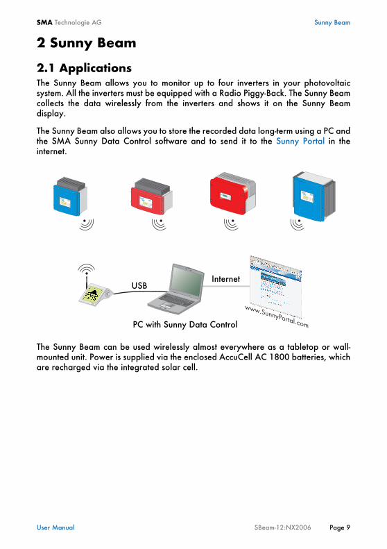
2.1 ApplicationsThe Sunny Beam allows you to monitor up to four inverters in your photovoltaicsystem. All the inverters must be equipped with a Radio Piggy-Back. The Sunny Beamcollects the data wirelessly from the inverters and shows it on the Sunny Beamdisplay.
The Sunny Beam also allows you to store the recorded data long-term using a PC andthe SMA Sunny Data Control software and to send it to the Sunny Portal in theinternet.
The Sunny Beam can be used wirelessly almost everywhere as a tabletop or wall-mounted unit. Power is supplied via the enclosed AccuCell AC 1800 batteries, whichare recharged via the integrated solar cell.
USBInternet
PC with Sunny Data Control
Sunny Beam SMA Technologie AG
Page10 SBeam-12:NX2006 User Manual
2.2 FunctionsThe device can be connected to the inverters via:• Wireless (radio) (up to approx. 100 m in open air, up to approx. 30 m in
buildings, max. 4 inverters)
Supported inverters:• Sunny Boys type
- SB700U- SB1100U- SB1800U- SB2500U- SB3800U- SB6000U
The device can be connected to the PC via:• USB (max. 2 m)
System data displayed via:• Integrated display in Sunny Beam• Sunny Portal (via Sunny Data Control and connected PC)
Sunny Beam installation site requirements:• Protect the Sunny Beam from dust, wet conditions and aggressive substances.• The ambient temperature must be between 0 °C and +40 °C.• The Sunny Beam is not suitable for outdoor installation.• Select a sunlit location in the house, so that the batteries can be charged via the
integrated solar cell of the Sunny Beam.
SMA Technologie AG Sunny Beam
User Manual SBeam-12:NX2006 Page 11
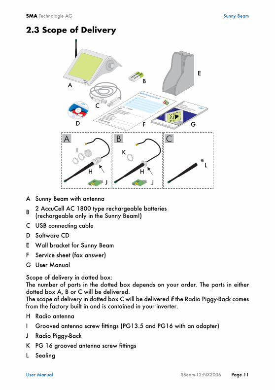
2.3 Scope of Delivery
Scope of delivery in dotted box:The number of parts in the dotted box depends on your order. The parts in eitherdotted box A, B or C will be delivered. The scope of delivery in dotted box C will be delivered if the Radio Piggy-Back comesfrom the factory built in and is contained in your inverter.
A Sunny Beam with antenna
B 2 AccuCell AC 1800 type rechargeable batteries (rechargeable only in the Sunny Beam!)
C USB connecting cable
D Software CD
E Wall bracket for Sunny Beam
F Service sheet (fax answer)
G User Manual
H Radio antenna
I Grooved antenna screw fittings (PG13.5 and PG16 with an adapter)
J Radio Piggy-Back
K PG 16 grooved antenna screw fittings
L Sealing
AB
C
D
E
F G
H
I
J
K
L
J
H
Sunny Beam SMA Technologie AG
Page12 SBeam-12:NX2006 User Manual
2.4 Accessories• USB power supply
SMA order number: SBEAM-NT• External antenna kit
SMA order number: BEAM-AW15 (with 1.5 m antenna extension cable)SMA order number: BEAM-AW100 (with 10 m antenna extension cable)
• Radio Piggy-Back retrofit kitSMA order number: BEAMPBU-NR-
• Spare batteries (AccuCell AC 1800)SMA order number: SBEAM-BAT
SMA Technologie AG Sunny Beam
User Manual SBeam-12:NX2006 Page 13
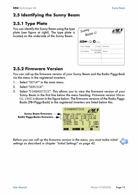
2.5 Identifying the Sunny Beam
2.5.1 Type PlateYou can identify the Sunny Beam using the typeplate (see figure at right). The type plate islocated on the underside of the Sunny Beam.
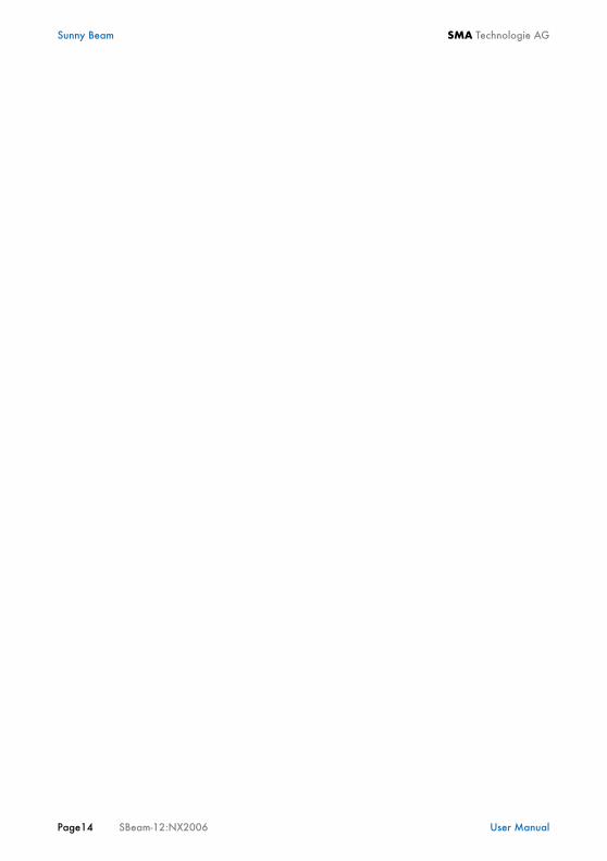
2.5.2 Firmware VersionYou can call up the firmware version of your Sunny Beam and the Radio Piggy-Backvia the menu in the registered inverters.1. Select "SETUP" in the main menu.2. Select "SERVICE".3. Select "DIAGNOSTICS". This allows you to view the firmware version of your
Sunny Beam in the first line below the menu heading. Firmware version SBeamV2.19US is shown in the figure below. The firmware versions of the Radio Piggy-Backs (PB=Piggy-Back) in the registered inverters are listed below this.
Before you can call up the firmware version in the menu, you must make initialsettings as described in chapter “Initial Settings" on page 42.
DIAGNOSTICS
SBeam V2.19US firmware 1.PB V:2.17 2.PB V:2.19 3.PB V:0.00 4.PB V:0.00 DEVICE S LS LR .67890: 204 0 0 100%
3.07V
.67891: 204 0 0 100%
Radio Piggy-Backs firmwareSunny Beam firmware
Sunny Beam SMA Technologie AG
Page14 SBeam-12:NX2006 User Manual

SMA Technologie AG Safety Instructions
User Manual SBeam-12:NX2006 Page 15
3 Safety InstructionsPlease follow all operating and safety instructions in this manual. Failure to do socould result in damage to the device and cause personal injury.
Operating instructions
All work on the inverters may only be performed by qualifiedelectricians! Please follow all safety instructions contained in theinverter documentation!
You can change the safety-related inverter parameters of your PVsystem using the sunny beam. The following guidelines must bemaintained:
- guidelines of the energy supply company- Solar manufacturer's specifications- national law
When in doubt, contact your competent authority.
The Sunny Beam may only be opened by qualified SMA staff. Thisdoes not apply to battery changes.
Our Sunny Boy Service Hotline is available for questions on details not coveredin this manual. See chapter “Contact" on page 89.
Data collected by the Sunny Beam regarding the power generated by yoursolar system can deviate from the electricity meter. The Sunny Beam datacannot be used for billing purposes.

Safety Instructions SMA Technologie AG
Page16 SBeam-12:NX2006 User Manual
SMA Technologie AG Mounting the Sunny Beam
User Manual SBeam-12:NX2006 Page 17
4 Mounting the Sunny BeamThe Sunny Beam can be used as a tabletop device or mounted on the wall bracket.
Suitable installation and assembly site• Protect the Sunny Beam from dust, wet conditions and aggressive substances.• For mounting and installation, select a location out of the reach of children.• Select a sunlit location in the house, so that the batteries can be charged via the
integrated solar cell of the Sunny Beam.• The ambient temperature must be between 0 °C and +40 °C.• If you use the wall bracket, ensure that there is sufficient mounting space around
the wall bracket.
4.1 Tabletop DeviceThe Sunny Beam can be installed anywhere in the building if the above points onselecting a suitable installation location are observed.
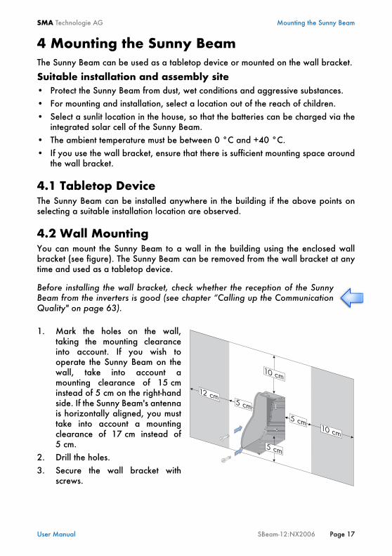
4.2 Wall MountingYou can mount the Sunny Beam to a wall in the building using the enclosed wallbracket (see figure). The Sunny Beam can be removed from the wall bracket at anytime and used as a tabletop device.
1. Mark the holes on the wall,taking the mounting clearanceinto account. If you wish tooperate the Sunny Beam on thewall, take into account amounting clearance of 15 cminstead of 5 cm on the right-handside. If the Sunny Beam's antennais horizontally aligned, you musttake into account a mountingclearance of 17 cm instead of5 cm.
2. Drill the holes.3. Secure the wall bracket with
screws.
Before installing the wall bracket, check whether the reception of the SunnyBeam from the inverters is good (see chapter “Calling up the CommunicationQuality" on page 63).
Mounting the Sunny Beam SMA Technologie AG
Page18 SBeam-12:NX2006 User Manual
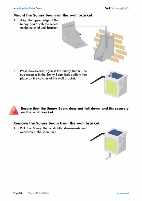
Mount the Sunny Beam on the wall bracket.1. Align the upper edge of the
Sunny Beam with the recesson the catch of wall bracket.
2. Press downwards against the Sunny Beam. Thetwo recesses in the Sunny Beam lock audibly intoplace on the catches of the wall bracket.
Remove the Sunny Beam from the wall bracket1. Pull the Sunny Beam slightly downwards and
outwards at the same time.
Ensure that the Sunny Beam does not fall down and fits securelyon the wall bracket.
SMA Technologie AG Installing a Radio Piggy-Back in an Inverter
User Manual SBeam-12:NX2006 Page 19
5 Installing a Radio Piggy-Back in an Inverter
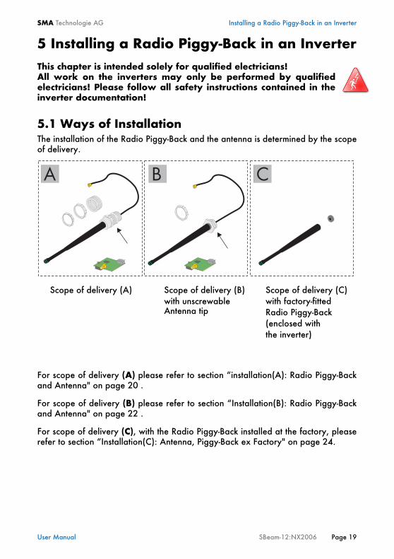
5.1 Ways of InstallationThe installation of the Radio Piggy-Back and the antenna is determined by the scopeof delivery.
For scope of delivery (A) please refer to section “installation(A): Radio Piggy-Backand Antenna" on page 20 .
For scope of delivery (B) please refer to section “Installation(B): Radio Piggy-Backand Antenna" on page 22 .
For scope of delivery (C), with the Radio Piggy-Back installed at the factory, pleaserefer to section “Installation(C): Antenna, Piggy-Back ex Factory" on page 24.
This chapter is intended solely for qualified electricians!All work on the inverters may only be performed by qualifiedelectricians! Please follow all safety instructions contained in theinverter documentation!
Scope of delivery (A)with unscrewableScope of delivery (B)
Antenna tip
Scope of delivery (C)with factory-fittedRadio Piggy-Back(enclosed with the inverter)
Installing a Radio Piggy-Back in an Inverter SMA Technologie AG
Page20 SBeam-12:NX2006 User Manual
5.1.1 installation(A): Radio Piggy-Back and AntennaThis section refers solely to scope of delivery (A). For the different scopes of delivery,please refer to section “Installing a Radio Piggy-Back in an Inverter" on page 19.
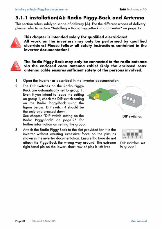
1. Open the inverter as described in the inverter documentation.2. The DIP switches on the Radio Piggy-
Back are automatically set to group 1.Even if you intend to leave the settingon group 1, check the DIP switch settingon the Radio Piggy-Back using thefigure below. DIP switch 4 should bethe only one pressed down. See chapter “DIP switch setting on theRadio Piggy-Back" on page 25 forfurther information on setting the group.
3. Attach the Radio Piggy-Back to the slot provided for it in theinverter without exerting excessive force on the pins asshown in the inverter documentation. Ensure tha tyou do notattach the Piggy-Back the wrong way around. The extremeright-hand pin on the lower, short row of pins is left free.
This chapter is intended solely for qualified electricians!All work on the inverters may only be performed by qualifiedelectricians! Please follow all safety instructions contained in theinverter documentation!
The Radio Piggy-Back may only be connected to the radio antennavia the enclosed coax antenna cable! Only the enclosed coaxantenna cable ensures sufficient safety of the persons involved.
DIP switches
DIP switches setto group 1

SMA Technologie AG Installing a Radio Piggy-Back in an Inverter
User Manual SBeam-12:NX2006 Page 21
4. Rotate the PG cover away from the inverter housing. The PG screw fitting whichfits your inverter is specified on the PG cover.
5. For a PG 16 screw fitting, screw theenclosed PG 16 adapter to the PG screwfitting of the antenna as shown in thefigure.
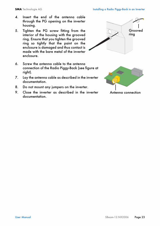
6. Insert the end of the antenna cablethrough the PG opening on the inverterhousing.
7. Tighten the PG screw fitting from theinterior of the housing with the groovedring of the corresponding PG screwfitting. Ensure that you tighten thegrooved ring so tightly that the paint onthe enclosure is damaged and thuscontact is made with the bare metal ofthe inverter enclosure.
8. Screw the antenna cable to the antennaconnection of the Radio Piggy-Back (see figure atright).
9. Lay the antenna cable as described in the inverterdocumentation.
10. Do not mount any jumpers on the inverter.11. Close the inverter as described in the inverter
documentation.
PG 16 adapter
Groovedring
for PG16 screw fitting only
Antenna connection
Installing a Radio Piggy-Back in an Inverter SMA Technologie AG
Page22 SBeam-12:NX2006 User Manual
5.1.2 Installation(B): Radio Piggy-Back and AntennaThis section refers solely to scope of delivery (B). For the different scopes of delivery,please refer to section “Installing a Radio Piggy-Back in an Inverter" on page 19.
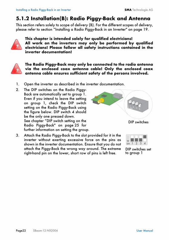
1. Open the inverter as described in the inverter documentation.2. The DIP switches on the Radio Piggy-
Back are automatically set to group 1.Even if you intend to leave the settingon group 1, check the DIP switchsetting on the Radio Piggy-Back usingthe figure below. DIP switch 4 shouldbe the only one pressed down. See chapter “DIP switch setting on theRadio Piggy-Back" on page 25 forfurther information on setting the group.
3. Attach the Radio Piggy-Back to the slot provided for it in theinverter without exerting excessive force on the pins asshown in the inverter documentation. Ensure that you do notattach the Piggy-Back the wrong way around. The extremeright-hand pin on the lower, short row of pins is left free.
This chapter is intended solely for qualified electricians!All work on the inverters may only be performed by qualifiedelectricians! Please follow all safety instructions contained in theinverter documentation!
The Radio Piggy-Back may only be connected to the radio antennavia the enclosed coax antenna cable! Only the enclosed coaxantenna cable ensures sufficient safety of the persons involved.
DIP switches
DIP switches setto group 1
SMA Technologie AG Installing a Radio Piggy-Back in an Inverter
User Manual SBeam-12:NX2006 Page 23
4. Insert the end of the antenna cablethrough the PG opening on the inverterhousing.
5. Tighten the PG screw fitting from theinterior of the housing with the groovedring. Ensure that you tighten the groovedring so tightly that the paint on theenclosure is damaged and thus contact ismade with the bare metal of the inverterenclosure.
6. Screw the antenna cable to the antennaconnection of the Radio Piggy-Back (see figure atright).
7. Lay the antenna cable as described in the inverterdocumentation.
8. Do not mount any jumpers on the inverter.9. Close the inverter as described in the inverter
documentation.
Groovedring
Antenna connection
Installing a Radio Piggy-Back in an Inverter SMA Technologie AG
Page24 SBeam-12:NX2006 User Manual
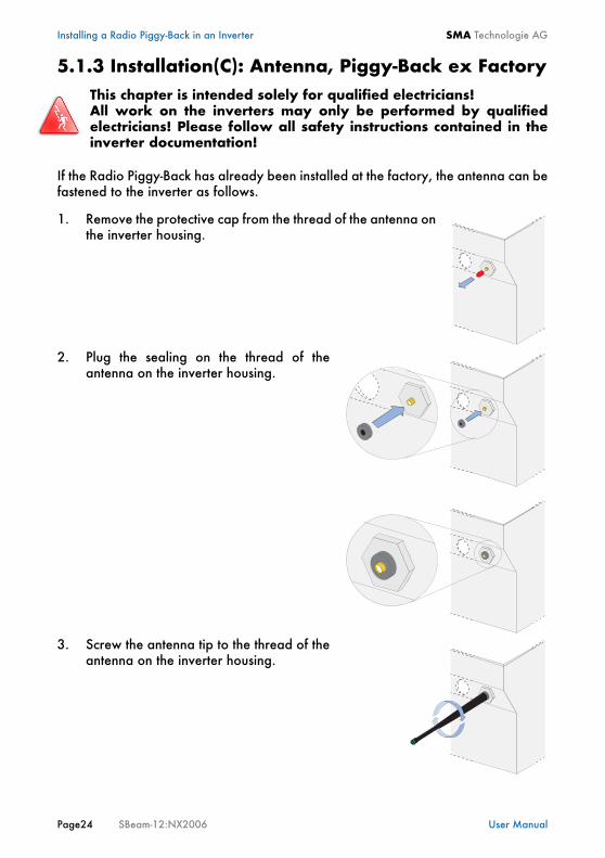
5.1.3 Installation(C): Antenna, Piggy-Back ex Factory
If the Radio Piggy-Back has already been installed at the factory, the antenna can befastened to the inverter as follows.
1. Remove the protective cap from the thread of the antenna onthe inverter housing.
2. Plug the sealing on the thread of theantenna on the inverter housing.
3. Screw the antenna tip to the thread of theantenna on the inverter housing.
This chapter is intended solely for qualified electricians!All work on the inverters may only be performed by qualifiedelectricians! Please follow all safety instructions contained in theinverter documentation!
SMA Technologie AG Installing a Radio Piggy-Back in an Inverter
User Manual SBeam-12:NX2006 Page 25
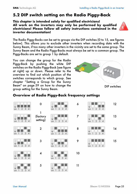
5.2 DIP switch setting on the Radio Piggy-Back
The Radio Piggy-Backs can be set to groups via the DIP switches (0 to 15, see figuresbelow). This allows you to exclude other inverters when recording data with theSunny Beam, if too many other inverters in the vicinity are set to the same group. TheSunny Beam and the Radio Piggy-Backs must always be set to a common group. ThePiggy-Backs are set to group 1 by default.
You can change the group for the RadioPiggy-Back by pushing the white DIPswitches on the Radio Piggy-Back (see figureat right) up or down. Please refer to theoverview to find out which position of theswitches corresponds to which group. Seechapter “Setting a Group for the SunnyBeam" on page 59 on how to change thegroup setting for the Sunny Beam.
Overview of Radio Piggy-Back frequency settings
This chapter is intended solely for qualified electricians!All work on the inverters may only be performed by qualifiedelectricians! Please follow all safety instructions contained in theinverter documentation!
0 6 12
1(factory setting)
7 13
2 8 14
3 9 15
4 10
5 11
DIP switches
Installing a Radio Piggy-Back in an Inverter SMA Technologie AG
Page26 SBeam-12:NX2006 User Manual
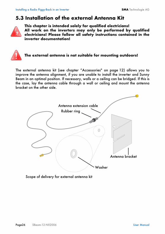
5.3 Installation of the external Antenna Kit
The external antenna kit (see chapter “Accessories" on page 12) allows you toimprove the antenna alignment, if you are unable to install the inverter and SunnyBeam in an optimal position. If necessary, walls or a ceiling can be bridged. If this isthe case, lay the antenna cable through a wall or ceiling and mount the antennabracket on the other side.
This chapter is intended solely for qualified electricians!All work on the inverters may only be performed by qualifiedelectricians! Please follow all safety instructions contained in theinverter documentation!
The external antenna is not suitable for mounting outdoors!
Washer
Rubber ringAntenna extension cable
Antenna bracket
Scope of delivery for external antenna kit
SMA Technologie AG Installing a Radio Piggy-Back in an Inverter
User Manual SBeam-12:NX2006 Page 27
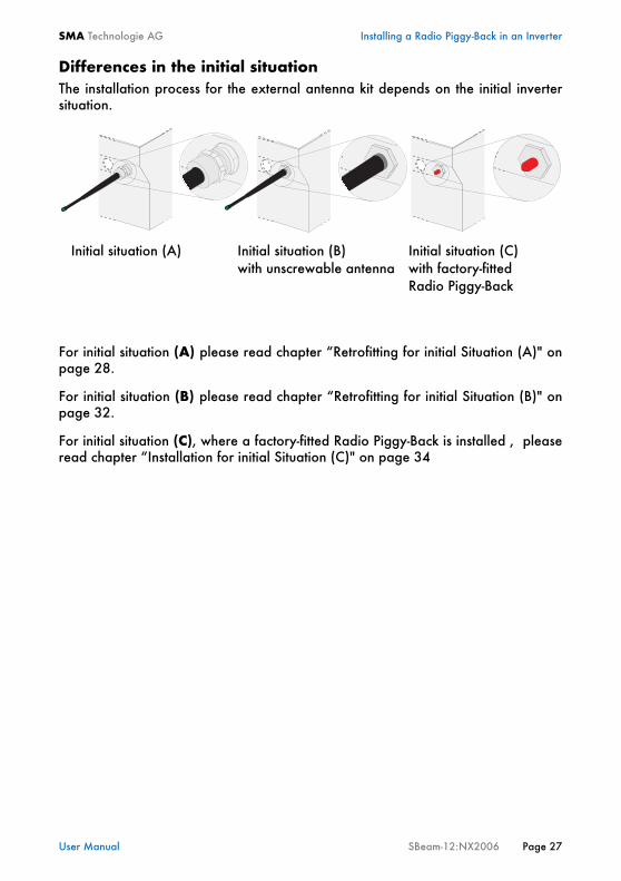
Differences in the initial situationThe installation process for the external antenna kit depends on the initial invertersituation.
For initial situation (A) please read chapter “Retrofitting for initial Situation (A)" onpage 28.
For initial situation (B) please read chapter “Retrofitting for initial Situation (B)" onpage 32.
For initial situation (C), where a factory-fitted Radio Piggy-Back is installed , pleaseread chapter “Installation for initial Situation (C)" on page 34
Initial situation (A) Initial situation (B)with unscrewable antenna
Initial situation (C)with factory-fittedRadio Piggy-Back
Installing a Radio Piggy-Back in an Inverter SMA Technologie AG
Page28 SBeam-12:NX2006 User Manual
5.3.1 Retrofitting for initial Situation (A)
This chapter only relates to initial situation (A). To distinguish between the differentinitial situations, refer to chapter “Installation of the external Antenna Kit" onpage 26.
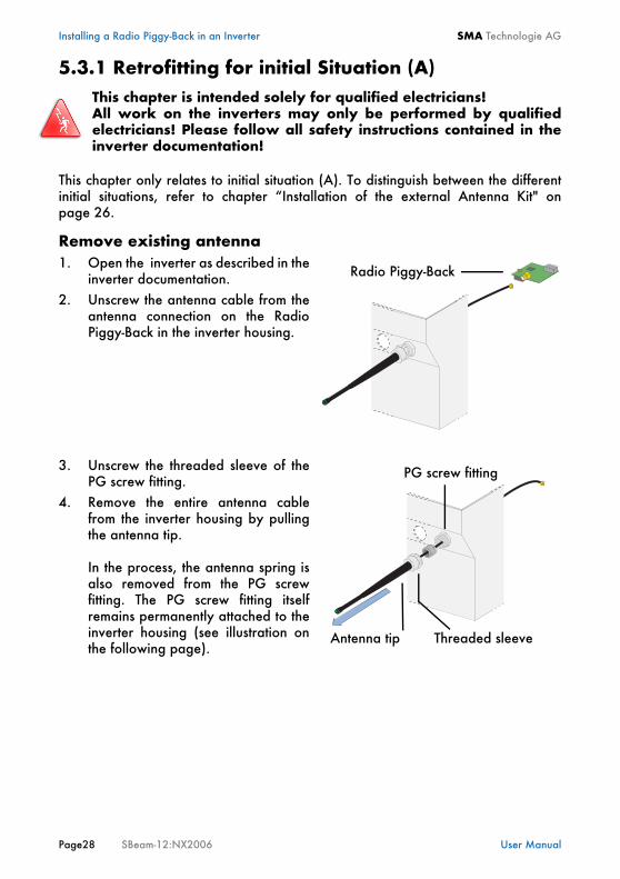
Remove existing antenna1. Open the inverter as described in the
inverter documentation.2. Unscrew the antenna cable from the
antenna connection on the RadioPiggy-Back in the inverter housing.
3. Unscrew the threaded sleeve of thePG screw fitting.
4. Remove the entire antenna cablefrom the inverter housing by pullingthe antenna tip.
In the process, the antenna spring isalso removed from the PG screwfitting. The PG screw fitting itselfremains permanently attached to theinverter housing (see illustration onthe following page).
This chapter is intended solely for qualified electricians!All work on the inverters may only be performed by qualifiedelectricians! Please follow all safety instructions contained in theinverter documentation!
Radio Piggy-Back
Antenna tip Threaded sleeve
PG screw fitting
SMA Technologie AG Installing a Radio Piggy-Back in an Inverter
User Manual SBeam-12:NX2006 Page 29
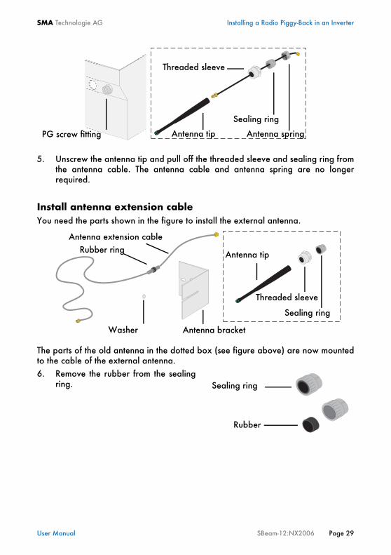
5. Unscrew the antenna tip and pull off the threaded sleeve and sealing ring fromthe antenna cable. The antenna cable and antenna spring are no longerrequired.
Install antenna extension cableYou need the parts shown in the figure to install the external antenna.
The parts of the old antenna in the dotted box (see figure above) are now mountedto the cable of the external antenna.6. Remove the rubber from the sealing
ring.
Antenna spring
Sealing ring
Threaded sleeve
Antenna tipPG screw fitting
Threaded sleeve
Sealing ring
Antenna bracketWasher
Rubber ringAntenna extension cable
Antenna tip
Sealing ring
Rubber
Installing a Radio Piggy-Back in an Inverter SMA Technologie AG
Page30 SBeam-12:NX2006 User Manual
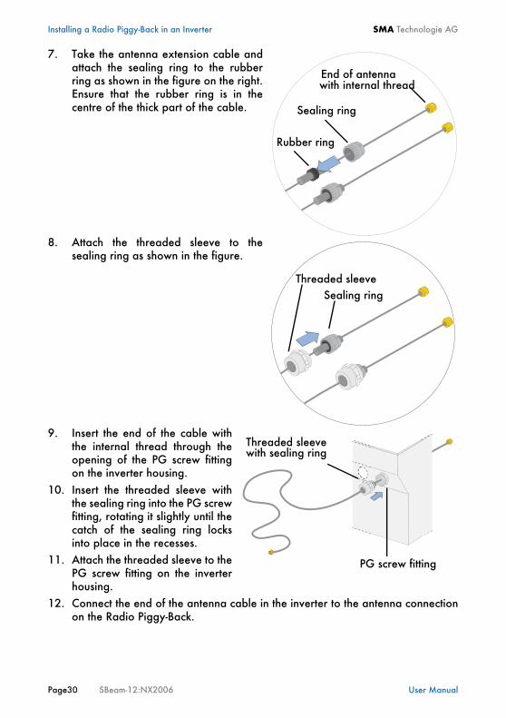
7. Take the antenna extension cable andattach the sealing ring to the rubberring as shown in the figure on the right.Ensure that the rubber ring is in thecentre of the thick part of the cable.
8. Attach the threaded sleeve to thesealing ring as shown in the figure.
9. Insert the end of the cable withthe internal thread through theopening of the PG screw fittingon the inverter housing.
10. Insert the threaded sleeve withthe sealing ring into the PG screwfitting, rotating it slightly until thecatch of the sealing ring locksinto place in the recesses.
11. Attach the threaded sleeve to thePG screw fitting on the inverterhousing.
12. Connect the end of the antenna cable in the inverter to the antenna connectionon the Radio Piggy-Back.
Rubber ring
Sealing ring
End of antennawith internal thread
Threaded sleeveSealing ring
PG screw fitting
Threaded sleevewith sealing ring

SMA Technologie AG Installing a Radio Piggy-Back in an Inverter
User Manual SBeam-12:NX2006 Page 31
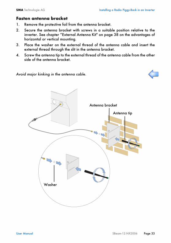
Fasten antenna bracket1. Remove the protective foil from the antenna bracket.2. Secure the antenna bracket with screws in a suitable position relative to the
inverter. See chapter “External Antenna Kit" on page 38 on the advantages ofhorizontal or vertical mounting.
3. Place the washer on the external thread of the antenna cable and insert theexternal thread through the slit in the antenna bracket.
4. Screw the antenna tip to the external thread of the antenna cable from the otherside of the antenna bracket.
Avoid major kinking in the antenna cable.
Washer
Antenna bracket
Antenna tip
Installing a Radio Piggy-Back in an Inverter SMA Technologie AG
Page32 SBeam-12:NX2006 User Manual
5.3.2 Retrofitting for initial Situation (B)
This chapter only relates to initial situation (B). To distinguish between the differentinitial situations, refer to chapter “Installation of the external Antenna Kit" onpage 26.
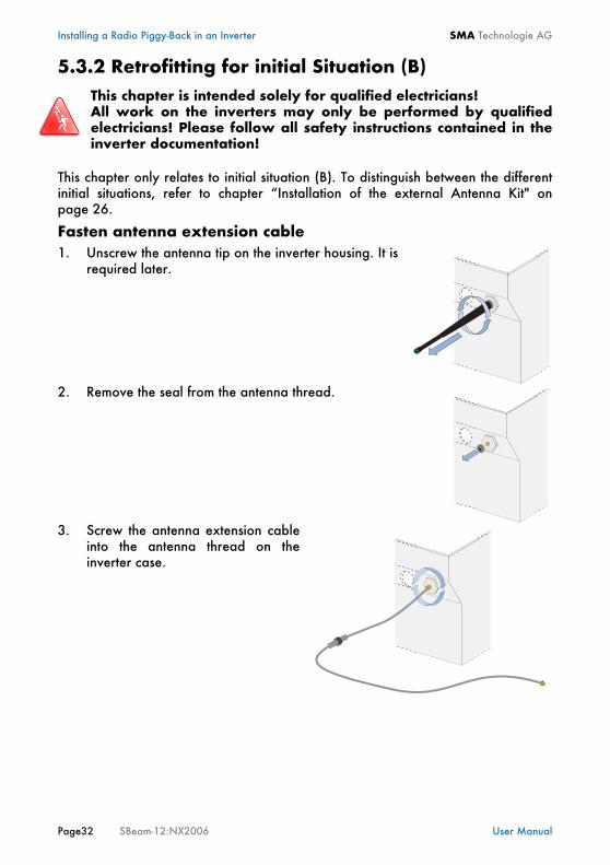
Fasten antenna extension cable1. Unscrew the antenna tip on the inverter housing. It is
required later.
2. Remove the seal from the antenna thread.
3. Screw the antenna extension cableinto the antenna thread on theinverter case.
This chapter is intended solely for qualified electricians!All work on the inverters may only be performed by qualifiedelectricians! Please follow all safety instructions contained in theinverter documentation!
SMA Technologie AG Installing a Radio Piggy-Back in an Inverter
User Manual SBeam-12:NX2006 Page 33
Fasten antenna bracket1. Remove the protective foil from the antenna bracket.2. Secure the antenna bracket with screws in a suitable position relative to the
inverter. See chapter “External Antenna Kit" on page 38 on the advantages ofhorizontal or vertical mounting.
3. Place the washer on the external thread of the antenna cable and insert theexternal thread through the slit in the antenna bracket.
4. Screw the antenna tip to the external thread of the antenna cable from the otherside of the antenna bracket.
Avoid major kinking in the antenna cable.
Washer
Antenna bracket
Antenna tip

Installing a Radio Piggy-Back in an Inverter SMA Technologie AG
Page34 SBeam-12:NX2006 User Manual
5.3.3 Installation for initial Situation (C)This chapter only relates to initial situation (C). If the Sunny Beam Piggy-Back hasalready been installed at the factory, then the external antenna kit can be installedon the inverter in the following manner. To distinguish between the different initialsituations, refer to chapter “Installation of the external Antenna Kit" on page 26.
Fasten antenna extension cable1. Remove the protective cap from the thread of the antenna on
the inverter housing.
2. Screw the antenna extension cableinto the antenna thread on theinverter case.

SMA Technologie AG Installing a Radio Piggy-Back in an Inverter
User Manual SBeam-12:NX2006 Page 35
Fasten antenna bracket3. Remove the protective foil from the antenna bracket.4. Secure the antenna bracket with screws in a suitable position relative to the
inverter. See chapter “External Antenna Kit" on page 38 on the advantages ofhorizontal or vertical mounting.
5. Place the washer on the external thread of the antenna cable and insert theexternal thread through the slit in the antenna bracket.
6. Screw the antenna tip to the external thread of the antenna cable from the otherside of the antenna bracket.
Avoid major kinking in the antenna cable.
Washer
Antenna bracket
Antenna tip
Installing a Radio Piggy-Back in an Inverter SMA Technologie AG
Page36 SBeam-12:NX2006 User Manual
5.4 Basic Information on Radio TransferThe radio range from the antenna on the inverter to the Sunny Beam in buildings is30 m and up to 100 m in the open air. The ambient conditions and the distance fromthe Sunny Beam to the antenna on the inverter are the critical factors for the radiorange. The greater the absorbing qualities of walls, doors etc., the lower the range.
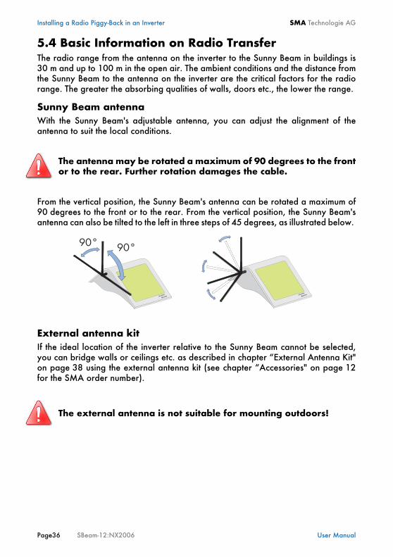
Sunny Beam antennaWith the Sunny Beam's adjustable antenna, you can adjust the alignment of theantenna to suit the local conditions.
From the vertical position, the Sunny Beam's antenna can be rotated a maximum of90 degrees to the front or to the rear. From the vertical position, the Sunny Beam'santenna can also be tilted to the left in three steps of 45 degrees, as illustrated below.
External antenna kitIf the ideal location of the inverter relative to the Sunny Beam cannot be selected,you can bridge walls or ceilings etc. as described in chapter “External Antenna Kit"on page 38 using the external antenna kit (see chapter “Accessories" on page 12for the SMA order number).
The antenna may be rotated a maximum of 90 degrees to the frontor to the rear. Further rotation damages the cable.
The external antenna is not suitable for mounting outdoors!

SMA Technologie AG Installing a Radio Piggy-Back in an Inverter
User Manual SBeam-12:NX2006 Page 37
5.4.1 Antenna on InverterStandard case from storey to storeyIf you installed your inverter e.g. in the attic of your building, ensure that the SunnyBeam is not in the dead spot directly below the inverter in the building. If you still have poor reception in the building, you can use the external antenna kitto bridge ceilings or walls, as described in chapter “External Antenna Kit" onpage 38.
Dead spot
Installing a Radio Piggy-Back in an Inverter SMA Technologie AG
Page38 SBeam-12:NX2006 User Manual
5.4.2 External Antenna KitThe external antenna kit (see chapter “Accessories" on page 12 for SMA ordernumber) can be installed horizontally and vertically, which allows the antennaposition to be adjusted for local conditions.
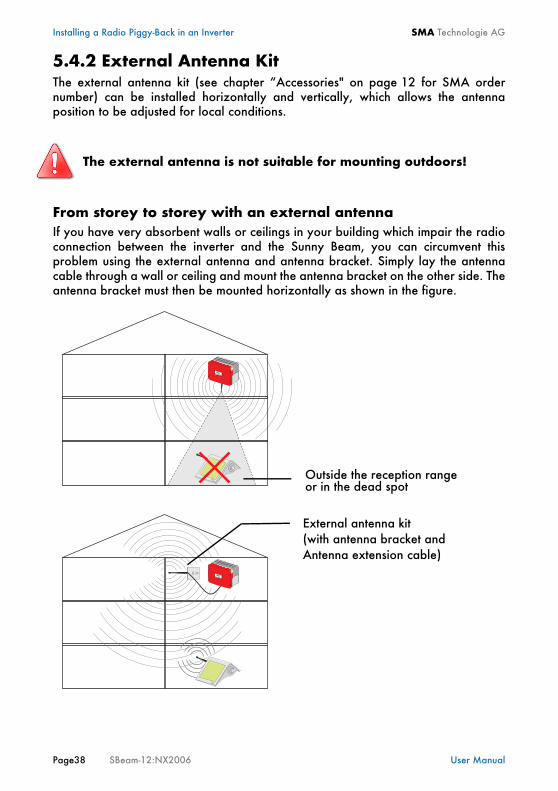
From storey to storey with an external antennaIf you have very absorbent walls or ceilings in your building which impair the radioconnection between the inverter and the Sunny Beam, you can circumvent thisproblem using the external antenna and antenna bracket. Simply lay the antennacable through a wall or ceiling and mount the antenna bracket on the other side. Theantenna bracket must then be mounted horizontally as shown in the figure.
The external antenna is not suitable for mounting outdoors!
Outside the reception range
External antenna kit
or in the dead spot
(with antenna bracket andAntenna extension cable)
SMA Technologie AG Installing a Radio Piggy-Back in an Inverter
User Manual SBeam-12:NX2006 Page 39
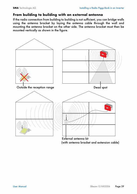
From building to building with an external antennaIf the radio connection from building to building is not sufficient, you can bridge wallsusing the antenna bracket by laying the antenna cable through the wall andmounting the antenna bracket on the other side. The antenna bracket must then bemounted vertically as shown in the figure.
External antenna kit
Dead spotOutside the reception range
(with antenna bracket and extension cable)
Installing a Radio Piggy-Back in an Inverter SMA Technologie AG
Page40 SBeam-12:NX2006 User Manual
SMA Technologie AG Operating the Sunny Beam
User Manual SBeam-12:NX2006 Page 41
6 Operating the Sunny Beam
6.1 Inserting the Batteries
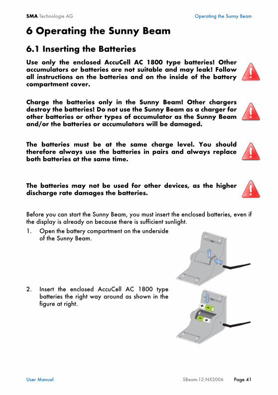
Before you can start the Sunny Beam, you must insert the enclosed batteries, even ifthe display is already on because there is sufficient sunlight.1. Open the battery compartment on the underside
of the Sunny Beam.
2. Insert the enclosed AccuCell AC 1800 typebatteries the right way around as shown in thefigure at right.
Use only the enclosed AccuCell AC 1800 type batteries! Otheraccumulators or batteries are not suitable and may leak! Followall instructions on the batteries and on the inside of the batterycompartment cover.
Charge the batteries only in the Sunny Beam! Other chargersdestroy the batteries! Do not use the Sunny Beam as a charger forother batteries or other types of accumulator as the Sunny Beamand/or the batteries or accumulators will be damaged.
The batteries must be at the same charge level. You shouldtherefore always use the batteries in pairs and always replaceboth batteries at the same time.
The batteries may not be used for other devices, as the higherdischarge rate damages the batteries.
Operating the Sunny Beam SMA Technologie AG
Page42 SBeam-12:NX2006 User Manual
6.2 Initial Startup
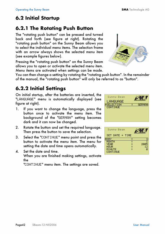
6.2.1 The Rotating Push ButtonThe "rotating push button" can be pressed and turnedback and forth (see figure at right). Rotating the"rotating push button" on the Sunny Beam allows youto select the individual menu items. The selection framewith an arrow always shows the selected menu item(see example figures below).Pressing the "rotating push button" on the Sunny Beamallows you to open or activate the selected menu item.Menu items are activated when settings can be made.You can then change a setting by rotating the "rotating push button". In the remainderof the manual, the "rotating push button" will only be referred to as "button".
6.2.2 Initial SettingsOn initial startup, after the batteries are inserted, the"LANGUAGE" menu is automatically displayed (seefigure at right).1. If you want to change the language, press the
button once to activate the menu item. Thebackground of the "GERMAN" setting becomesdark and it can now be changed.
2. Rotate the button and set the required language.Then press the button to save the selection.
3. Select the "CONTINUE" menu point and press thebutton to activate the menu item. The menu forsetting the date and time opens automatically.
4. Set the date and time.When you are finished making settings, activatethe "CONTINUE" menu item. The settings are saved.
LANGUAGESELECTION : GERMAN
CONTINUE
SET DATE + TIME
DAY : 1 MONTH : 1
CONTINUE
YEAR : 2005
MINUTE : 0 HOUR : 12
SMA Technologie AG Operating the Sunny Beam
User Manual SBeam-12:NX2006 Page 43
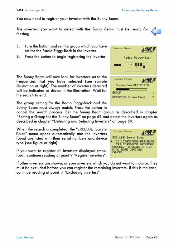
You now need to register your inverter with the Sunny Beam.
5. Turn the button and set the group which you haveset for the Radio Piggy-Back in the inverter.
6. Press the button to begin registering the inverter.
The Sunny Beam will now look for inverters set to thefrequencies that you have selected (see sampleillustration at right). The number of inverters detectedwill be indicated as shown in the illustration. Wait forthe search to end.
The group setting for the Radio Piggy-Back and theSunny Beam must always match. Press the button tocancel the search process. Set the Sunny Beam group as described in chapter“Setting a Group for the Sunny Beam" on page 59 and detect the inverters again asdescribed in chapter “Detecting and Selecting Inverters" on page 59.
When the search is completed, the "EXCLUDE SunnyBoys" menu opens automatically and the invertersfound are listed with their serial numbers and devicetype (see figure at right).
If you want to register all inverters displayed (max.four), continue reading at point 9 "Register inverters".
If other inverters are shown, or your inverters which you do not want to monitor, theymust be excluded before you can register the remaining inverters. If this is the case,continue reading at point 7 "Excluding inverters".
The inverters you want to detect with the Sunny Beam must be ready forfeeding.
Radio Piggy-Back
Sunny Boy DETECTION
GROUP 1
DETECTED Sunny Boys 2
EXCLUDE Sunny Boys
1:11234567890 WR11HX08
PROCEED TO REGISTRATION
FIND MORE DEVICES CANCEL
2:11234567891 WR50MS08

Operating the Sunny Beam SMA Technologie AG
Page44 SBeam-12:NX2006 User Manual
Excluding inverters7. Select an inverter you want to exclude from
monitoring and press the button. The serialnumber and the device type are crossed out onthe display (see figure at right). Repeat thisprocedure to exclude other inverters.
8. Activate the "FIND MORE DEVICES" menu itemto search for other inverters. Continue with point9 when all inverters you want to monitor are displayed.
Registering inverters9. Activate the
"PROCEED TO REGISTRATION" menu item.Sunny Beam then saves the inverters and switchesautomatically to the normal view at the end of theregistration process (see the figure at right). That completes the registration process.
If the Sunny Beam does not find any inverters, you can cancel the search by pressingthe button. The "EXCLUDE Sunny Boys" menu opens automatically. Activate"CANCEL" in the main menu. The main menu opens. Chapter “Troubleshooting/Problem Solving" on page 75contains troubleshooting instructions.
It may take a few minutes before the first system values are displayed.
EXCLUDE Sunny Boys
1:11234567890 WR11HX08
PROCEED TO REGISTRATION
FIND MORE DEVICES CANCEL
2:11234567891 WR50MS08
P1 : 54
SMA Technologie AG Operating the Sunny Beam
User Manual SBeam-12:NX2006 Page 45
6.3 The display Elements
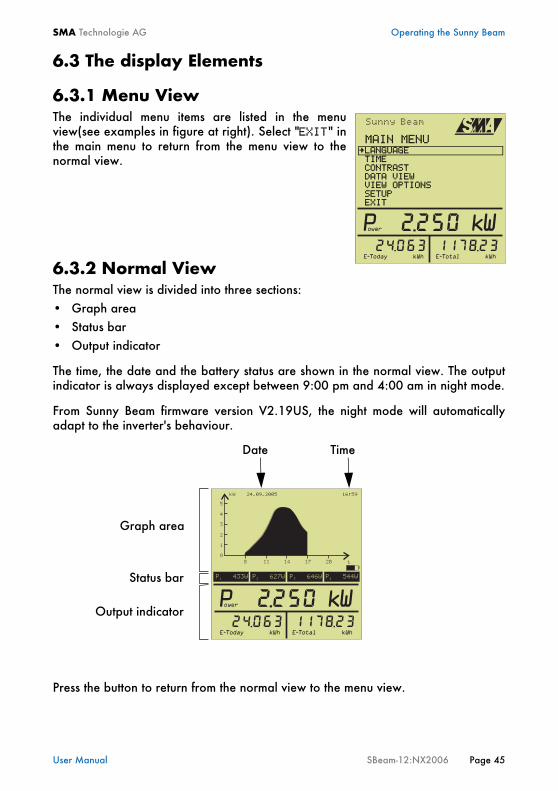
6.3.1 Menu ViewThe individual menu items are listed in the menuview(see examples in figure at right). Select "EXIT" inthe main menu to return from the menu view to thenormal view.
6.3.2 Normal ViewThe normal view is divided into three sections:• Graph area• Status bar• Output indicator
The time, the date and the battery status are shown in the normal view. The outputindicator is always displayed except between 9:00 pm and 4:00 am in night mode.
From Sunny Beam firmware version V2.19US, the night mode will automaticallyadapt to the inverter's behaviour.
Press the button to return from the normal view to the menu view.
MAIN MENULANGUAGE
TIME CONTRAST
EXIT
DATA VIEW
SETUP VIEW OPTIONS
Graph area
Status bar
Output indicator
Date Time
Operating the Sunny Beam SMA Technologie AG
Page46 SBeam-12:NX2006 User Manual
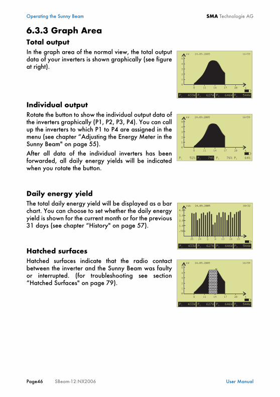
6.3.3 Graph AreaTotal outputIn the graph area of the normal view, the total outputdata of your inverters is shown graphically (see figureat right).
Individual outputRotate the button to show the individual output data ofthe inverters graphically (P1, P2, P3, P4). You can callup the inverters to which P1 to P4 are assigned in themenu (see chapter “Adjusting the Energy Meter in theSunny Beam" on page 55).After all data of the individual inverters has beenforwarded, all daily energy yields will be indicatedwhen you rotate the button.
Daily energy yieldThe total daily energy yield will be displayed as a barchart. You can choose to set whether the daily energyyield is shown for the current month or for the previous31 days (see chapter “History" on page 57).
Hatched surfacesHatched surfaces indicate that the radio contactbetween the inverter and the Sunny Beam was faultyor interrupted. (for troubleshooting see section“Hatched Surfaces" on page 79).
�� ���������� ���
� ��
� �� �
� � �
� � �
�
�
�
�
�
� � � �� �
aaaaaaaaaaaaaaaaaaaaaaaaaaaaaaaaaaaaaaaaaaaaaaaaaaaaaaaaaaaaaaa
SMA Technologie AG Operating the Sunny Beam
User Manual SBeam-12:NX2006 Page 47
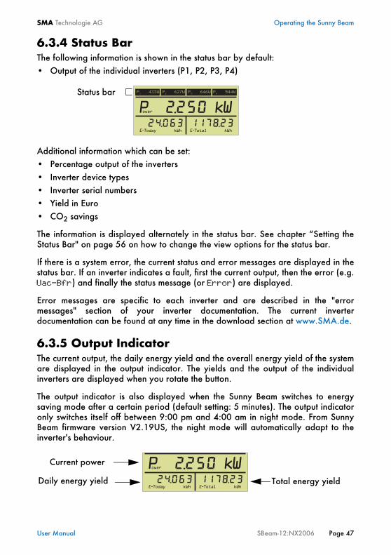
6.3.4 Status BarThe following information is shown in the status bar by default:• Output of the individual inverters (P1, P2, P3, P4)
Additional information which can be set:• Percentage output of the inverters• Inverter device types• Inverter serial numbers• Yield in Euro• CO2 savings
The information is displayed alternately in the status bar. See chapter “Setting theStatus Bar" on page 56 on how to change the view options for the status bar.
If there is a system error, the current status and error messages are displayed in thestatus bar. If an inverter indicates a fault, first the current output, then the error (e.g.Uac-Bfr) and finally the status message (or Error) are displayed.
Error messages are specific to each inverter and are described in the "errormessages" section of your inverter documentation. The current inverterdocumentation can be found at any time in the download section at www.SMA.de.
6.3.5 Output IndicatorThe current output, the daily energy yield and the overall energy yield of the systemare displayed in the output indicator. The yields and the output of the individualinverters are displayed when you rotate the button.
The output indicator is also displayed when the Sunny Beam switches to energysaving mode after a certain period (default setting: 5 minutes). The output indicatoronly switches itself off between 9:00 pm and 4:00 am in night mode. From SunnyBeam firmware version V2.19US, the night mode will automatically adapt to theinverter's behaviour.
Status bar
Current power
Daily energy yield Total energy yield
Operating the Sunny Beam SMA Technologie AG
Page48 SBeam-12:NX2006 User Manual
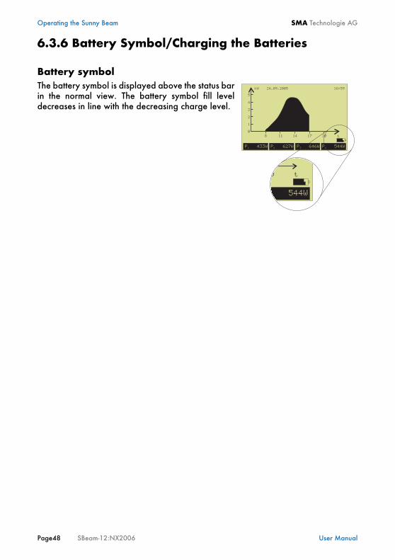
6.3.6 Battery Symbol/Charging the Batteries
Battery symbolThe battery symbol is displayed above the status barin the normal view. The battery symbol fill leveldecreases in line with the decreasing charge level.
SMA Technologie AG Operating the Sunny Beam
User Manual SBeam-12:NX2006 Page 49
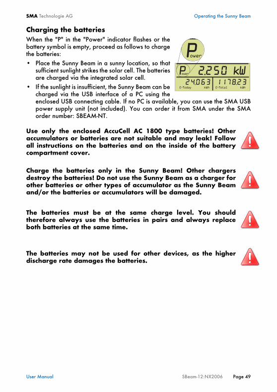
Charging the batteriesWhen the "P" in the "Power" indicator flashes or thebattery symbol is empty, proceed as follows to chargethe batteries:• Place the Sunny Beam in a sunny location, so that
sufficient sunlight strikes the solar cell. The batteriesare charged via the integrated solar cell.
• If the sunlight is insufficient, the Sunny Beam can becharged via the USB interface of a PC using theenclosed USB connecting cable. If no PC is available, you can use the SMA USBpower supply unit (not included). You can order it from SMA under the SMAorder number: SBEAM-NT.
Use only the enclosed AccuCell AC 1800 type batteries! Otheraccumulators or batteries are not suitable and may leak! Followall instructions on the batteries and on the inside of the batterycompartment cover.
Charge the batteries only in the Sunny Beam! Other chargersdestroy the batteries! Do not use the Sunny Beam as a charger forother batteries or other types of accumulator as the Sunny Beamand/or the batteries or accumulators will be damaged.
The batteries must be at the same charge level. You shouldtherefore always use the batteries in pairs and always replaceboth batteries at the same time.
The batteries may not be used for other devices, as the higherdischarge rate damages the batteries.
Operating the Sunny Beam SMA Technologie AG
Page50 SBeam-12:NX2006 User Manual
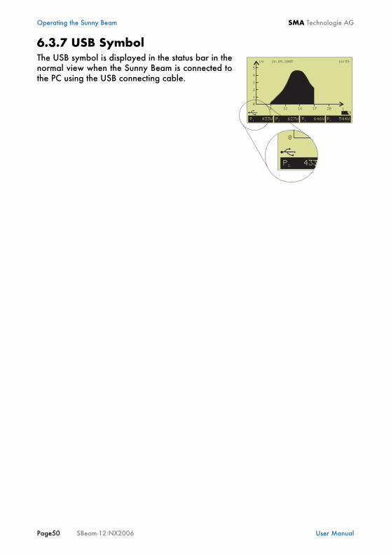
6.3.7 USB SymbolThe USB symbol is displayed in the status bar in thenormal view when the Sunny Beam is connected tothe PC using the USB connecting cable.
SMA Technologie AG Operating the Sunny Beam
User Manual SBeam-12:NX2006 Page 51
6.4 Sunny Beam Basic Settings
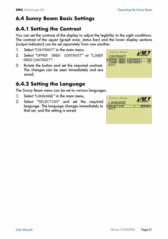
6.4.1 Setting the ContrastYou can set the contrast of the display to adjust the legibility to the sight conditions.The contrast of the upper (graph area, status bar) and the lower display sections(output indicator) can be set separately from one another.1. Select "CONTRAST" in the main menu.2. Select "UPPER AREA CONTRAST" or "LOWER
AREA CONTRAST".3. Rotate the button and set the required contrast.
The changes can be seen immediately and aresaved.
6.4.2 Setting the LanguageThe Sunny Beam menu can be set to various languages.1. Select "LANGUAGE" in the main menu.2. Select "SELECTION" and set the required
language. The language changes immediately tothat set, and the setting is saved.
CONTRASTUPPER AREA CONTRAST: 30
LOWER AREA CONTRAST: 18 EXIT
LANGUAGESELECTION : GERMAN
EXIT
Operating the Sunny Beam SMA Technologie AG
Page52 SBeam-12:NX2006 User Manual
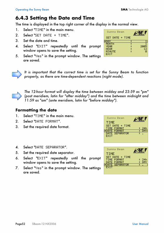
6.4.3 Setting the Date and TimeThe time is displayed in the top right corner of the display in the normal view.1. Select "TIME" in the main menu.2. Select "SET DATE + TIME".3. Set the date and time.4. Select "EXIT" repeatedly until the prompt
window opens to save the setting.5. Select "Yes" in the prompt window. The settings
are saved.
Formatting the date1. Select "TIME" in the main menu.2. Select "DATE FORMAT".3. Set the required date format.
4. Select "DATE SEPARATOR".5. Set the required date separator.6. Select "EXIT" repeatedly until the prompt
window opens to save the setting.7. Select "Yes" in the prompt window. The settings
are saved.
It is important that the correct time is set for the Sunny Beam to functionproperly, as there are time-dependent reactions (night mode).
The 12-hour format will display the time between midday and 23:59 as "pm"(post meridiem, latin for "after midday") and the time between midnight and11:59 as "am" (ante meridiem, latin for "before midday").
SET DATE + TIME
DAY : 1 MONTH : 1
EXIT
YEAR : 2005
MINUTE : 0 HOUR : 12
TIME SET DATE + TIME TIME FORMAT : 24hDATE FORMAT : DMY
DATE SEPARATOR : . EXIT
TIME SET DATE + TIME TIME FORMAT : 24h DATE FORMAT : DMY
DATE SEPARATOR : . EXIT
SMA Technologie AG Operating the Sunny Beam
User Manual SBeam-12:NX2006 Page 53
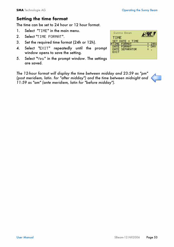
Setting the time formatThe time can be set to 24 hour or 12 hour format.1. Select "TIME" in the main menu.2. Select "TIME FORMAT".3. Set the required time format (24h or 12h). 4. Select "EXIT" repeatedly until the prompt
window opens to save the setting.5. Select "Yes" in the prompt window. The settings
are saved.
The 12-hour format will display the time between midday and 23:59 as "pm"(post meridiem, latin. for "after midday") and the time between midnight and11:59 as "am" (ante meridiem, latin for "before midday").
TIME SET DATE + TIMETIME FORMAT : 24h
DATE FORMAT : DMY
DATE SEPARATOR : . EXIT
Operating the Sunny Beam SMA Technologie AG
Page54 SBeam-12:NX2006 User Manual
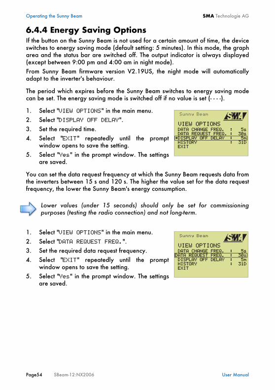
6.4.4 Energy Saving OptionsIf the button on the Sunny Beam is not used for a certain amount of time, the deviceswitches to energy saving mode (default setting: 5 minutes). In this mode, the grapharea and the status bar are switched off. The output indicator is always displayed(except between 9:00 pm and 4:00 am in night mode). From Sunny Beam firmware version V2.19US, the night mode will automaticallyadapt to the inverter's behaviour.
The period which expires before the Sunny Beam switches to energy saving modecan be set. The energy saving mode is switched off if no value is set (- - - -).
1. Select "VIEW OPTIONS" in the main menu.2. Select "DISPLAY OFF DELAY".3. Set the required time.4. Select "EXIT" repeatedly until the prompt
window opens to save the setting.5. Select "Yes" in the prompt window. The settings
are saved.
You can set the data request frequency at which the Sunny Beam requests data fromthe inverters between 15 s and 120 s. The higher the value set for the data requestfrequency, the lower the Sunny Beam's energy consumption.
1. Select "VIEW OPTIONS" in the main menu.2. Select "DATA REQUEST FREQ.".3. Set the required data request frequency.4. Select "EXIT" repeatedly until the prompt
window opens to save the setting.5. Select "Yes" in the prompt window. The settings
are saved.
Lower values (under 15 seconds) should only be set for commissioningpurposes (testing the radio connection) and not long-term.
VIEW OPTIONS DATA CHANGE FREQ. : 5s DATA REQUEST FREQ. : 30sDISPLAY OFF DELAY : 5m
HISTORY : 31D EXIT
VIEW OPTIONS DATA CHANGE FREQ. : 5sDATA REQUEST FREQ. : 30s DISPLAY OFF DELAY : 5m
HISTORY : 31D EXIT
SMA Technologie AG Operating the Sunny Beam
User Manual SBeam-12:NX2006 Page 55
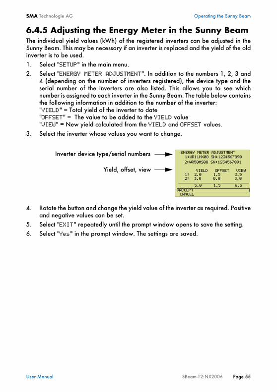
6.4.5 Adjusting the Energy Meter in the Sunny BeamThe individual yield values (kWh) of the registered inverters can be adjusted in theSunny Beam. This may be necessary if an inverter is replaced and the yield of the oldinverter is to be used.1. Select "SETUP" in the main menu.2. Select "ENERGY METER ADJUSTMENT". In addition to the numbers 1, 2, 3 and
4 (depending on the number of inverters registered), the device type and theserial number of the inverters are also listed. This allows you to see whichnumber is assigned to each inverter in the Sunny Beam. The table below containsthe following information in addition to the number of the inverter:"YIELD" = Total yield of the inverter to date"OFFSET" = The value to be added to the YIELD value"VIEW" = New yield calculated from the YIELD and OFFSET values.
3. Select the inverter whose values you want to change.
4. Rotate the button and change the yield value of the inverter as required. Positiveand negative values can be set.
5. Select "EXIT" repeatedly until the prompt window opens to save the setting.6. Select "Yes" in the prompt window. The settings are saved.
ENERGY METER ADJUSTMENT
YIELD OFFSET VIEW
1:WR11HX08 SN:1234567890
1: 2.0 1.5 3.5
CANCEL
ACCEPT
2:WR50MS08 SN:1234567891
5.0 1.5 6.5
2: 3.0 0.0 3.0
Inverter device type/serial numbers
Yield, offset, view
Operating the Sunny Beam SMA Technologie AG
Page56 SBeam-12:NX2006 User Manual
6.5 Setting the Status BarThe status bar is described in chapter “Status Bar" on page 47.
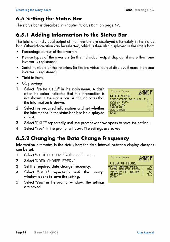
6.5.1 Adding Information to the Status BarThe total and individual output of the inverters are displayed alternately in the statusbar. Other information can be selected, which is then also displayed in the status bar:• Percentage output of the inverters• Device types of the inverters (in the individual output display, if more than one
inverter is registered)• Serial numbers of the inverters (in the individual output display, if more than one
inverter is registered)• Yield in Euro• CO2 savings1. Select "DATA VIEW" in the main menu. A dash
after the colon indicates that this information isnot shown in the status bar. A tick indicates thatthe information is shown.
2. Select the required information and set whetherthe information in the status bar is to be displayedor not.
3. Select "EXIT" repeatedly until the prompt window opens to save the setting.4. Select "Yes" in the prompt window. The settings are saved.
6.5.2 Changing the Data Change FrequencyInformation alternates in the status bar; the time interval between display changescan be set.1. Select "VIEW OPTIONS" in the main menu.2. Select "DATA CHANGE FREQ.".3. Set the required data change frequency.4. Select "EXIT" repeatedly until the prompt
window opens to save the setting.5. Select "Yes" in the prompt window. The settings
are saved.
DATA VIEW PERCENTAGE TO P-LIMIT : - DEVICE TYPE : - SERIAL NO : -
EARNINGS : -
EXITCO2 SAVED
VIEW OPTIONSDATA CHANGE FREQ. : 5s
DATA REQUEST FREQ. : 30s DISPLAY OFF DELAY : 5m
HISTORY : 31D EXIT
SMA Technologie AG Operating the Sunny Beam
User Manual SBeam-12:NX2006 Page 57
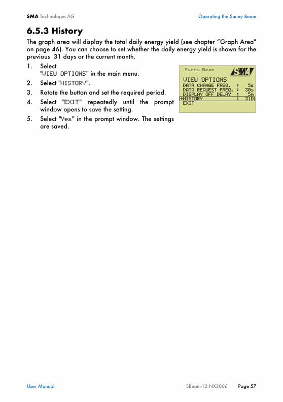
6.5.3 HistoryThe graph area will display the total daily energy yield (see chapter “Graph Area"on page 46). You can choose to set whether the daily energy yield is shown for theprevious 31 days or the current month. 1. Select
"VIEW OPTIONS" in the main menu.2. Select "HISTORY".3. Rotate the button and set the required period.4. Select "EXIT" repeatedly until the prompt
window opens to save the setting.5. Select "Yes" in the prompt window. The settings
are saved.
VIEW OPTIONS DATA CHANGE FREQ. : 5s DATA REQUEST FREQ. : 30s DISPLAY OFF DELAY : 5m
HISTORY : 31D EXIT

Operating the Sunny Beam SMA Technologie AG
Page58 SBeam-12:NX2006 User Manual
6.5.4 Setting Factors
6.5.4.1 Setting Yield per kWhThe yield per kWh depends on the location and system type.1. Select "SETUP" in the main menu.2. Select "COEFFICIENTS OF BALANCE".3. Select "EARNINGS/kWh".4. Rotate the button and set the required value.5. Select "EXIT" repeatedly until the prompt
window opens to save the setting.6. Select "Yes" in the prompt window. The settings are saved.
6.5.4.2 Setting the CurrencyYou can select different currencies.1. Select "SETUP" in the main menu.2. Select "COEFFICIENTS OF BALANCE".3. Select "CURRENCY".4. Rotate the button and set the required currency.5. Select "EXIT" repeatedly until the prompt
window opens to save the setting.6. Select "Yes" in the prompt window. The settings are saved.
6.5.4.3 Setting the CO2-savings FactorYour photovoltaic system contributes to reducing CO2 emissions. The CO2savings,e.g. compared with the current German electricity mix, is calculated with a factor of0.7. This factor is set by default. The calculation factors are country-specific.1. Select "SETUP" in the main menu.2. Select "COEFFICIENTS OF BALANCE".3. Select "kg CO2/kWh". 4. Rotate the button and set the corresponding
value.5. Select "EXIT" repeatedly until the prompt
window opens to save the setting.6. Select "Yes" in the prompt window. The settings are saved.
COEFFICIENTS OF BALANCE
EARNING/kWh : 0.5740 CURRENCY : kg CO2/kWh : 0.70
EXIT
$
COEFFICIENTS OF BALANCE
EARNINGS/kWh : 0.5740CURRENCY : kg CO2/kWh : 0.70
EXIT
$
COEFFICIENTS OF BALANCE
EARNINGS/kWh : 0.5740 CURRENCY : kg CO2/kWh : 0.70
EXIT
$
SMA Technologie AG Operating the Sunny Beam
User Manual SBeam-12:NX2006 Page 59
6.6 Service Settings
6.6.1 Setting a Group for the Sunny Beam
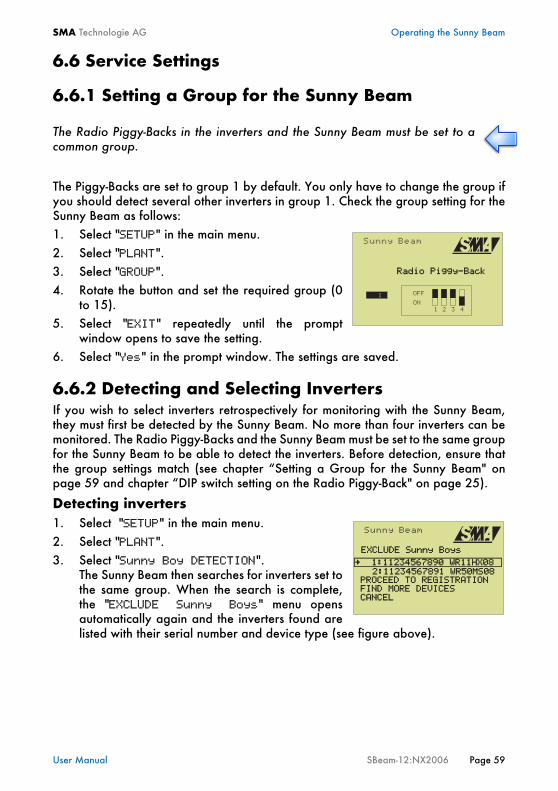
The Piggy-Backs are set to group 1 by default. You only have to change the group ifyou should detect several other inverters in group 1. Check the group setting for theSunny Beam as follows:1. Select "SETUP" in the main menu.2. Select "PLANT".3. Select "GROUP".4. Rotate the button and set the required group (0
to 15).5. Select "EXIT" repeatedly until the prompt
window opens to save the setting.6. Select "Yes" in the prompt window. The settings are saved.
6.6.2 Detecting and Selecting InvertersIf you wish to select inverters retrospectively for monitoring with the Sunny Beam,they must first be detected by the Sunny Beam. No more than four inverters can bemonitored. The Radio Piggy-Backs and the Sunny Beam must be set to the same groupfor the Sunny Beam to be able to detect the inverters. Before detection, ensure thatthe group settings match (see chapter “Setting a Group for the Sunny Beam" onpage 59 and chapter “DIP switch setting on the Radio Piggy-Back" on page 25).
Detecting inverters1. Select "SETUP" in the main menu.2. Select "PLANT".3. Select "Sunny Boy DETECTION".
The Sunny Beam then searches for inverters set tothe same group. When the search is complete,the "EXCLUDE Sunny Boys" menu opensautomatically again and the inverters found arelisted with their serial number and device type (see figure above).
The Radio Piggy-Backs in the inverters and the Sunny Beam must be set to acommon group.
Radio Piggy-Back
EXCLUDE Sunny Boys
1:11234567890 WR11HX08
PROCEED TO REGISTRATION
FIND MORE DEVICES CANCEL
2:11234567891 WR50MS08
Operating the Sunny Beam SMA Technologie AG
Page60 SBeam-12:NX2006 User Manual
If you want to register all inverters displayed (max. four), continue reading at point 6"Register inverters".
The Sunny Beam radio range may also have reached and found "other" inverters,e.g. those that are fitted in neighbouring buildings. If other inverters are shown, oryour inverters which you do not want to monitor, they must be excluded before youcan register the remaining inverters. If this is the case, continue reading at point 4"Excluding inverters".
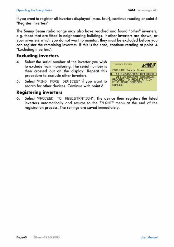
Excluding inverters4. Select the serial number of the inverter you wish
to exclude from monitoring. The serial number isthen crossed out on the display. Repeat thisprocedure to exclude other inverters.
5. Select "FIND MORE DEVICES" if you want tosearch for other devices. Continue with point 6.
Registering inverters6. Select "PROCEED TO REGISTRATION". The device then registers the listed
inverters automatically and returns to the "PLANT" menu at the end of theregistration process. The settings are saved immediately.
EXCLUDE Sunny Boys
1:11234567890 WR11HX08
PROCEED TO REGISTRATION
FIND MORE DEVICES CANCEL
2:11234567891 WR50MS08

SMA Technologie AG Operating the Sunny Beam
User Manual SBeam-12:NX2006 Page 61
6.6.3 Setting the Data Request FrequencyYou can set the data request frequency at which the Sunny Beam requests data fromthe inverters between 15 s and 120 s.
1. Select "VIEW OPTIONS" in the main menu.2. Select "DATA REQUEST FREQ.".3. Set the required data request frequency.4. Select "EXIT" repeatedly until the prompt
window opens to save the setting.5. Select "Yes" in the prompt window. The settings
are saved.
Lower values (under 15 seconds) should only be set for commissioningpurposes (testing the radio connection) and not long-term.
The lower the data request frequency value, the higher the Sunny Beam'senergy consumption.
VIEW OPTIONS DATA CHANGE FREQ. : 5sDATA REQUEST FREQ. : 30s
DISPLAY OFF DELAY : 5m
HISTORY : 31D EXIT
Operating the Sunny Beam SMA Technologie AG
Page62 SBeam-12:NX2006 User Manual
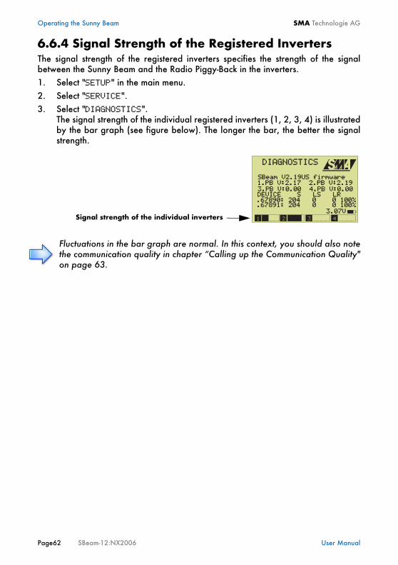
6.6.4 Signal Strength of the Registered InvertersThe signal strength of the registered inverters specifies the strength of the signalbetween the Sunny Beam and the Radio Piggy-Back in the inverters.1. Select "SETUP" in the main menu.2. Select "SERVICE".3. Select "DIAGNOSTICS".
The signal strength of the individual registered inverters (1, 2, 3, 4) is illustratedby the bar graph (see figure below). The longer the bar, the better the signalstrength.
Fluctuations in the bar graph are normal. In this context, you should also notethe communication quality in chapter “Calling up the Communication Quality"on page 63.
3.PB V:0.00 4.PB V:0.00
SBeam V2.19US firmware
DIAGNOSTICS
1.PB V:2.17 2.PB V:2.19
DEVICE S LS LR .67890: 204 0 0 100%
3.07V Signal strength of the individual inverters
.67891: 204 0 0 100%
SMA Technologie AG Operating the Sunny Beam
User Manual SBeam-12:NX2006 Page 63
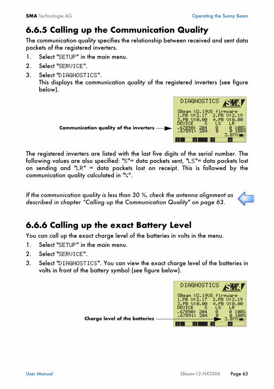
6.6.5 Calling up the Communication QualityThe communication quality specifies the relationship between received and sent datapackets of the registered inverters.1. Select "SETUP" in the main menu.2. Select "SERVICE".3. Select "DIAGNOSTICS".
This displays the communication quality of the registered inverters (see figurebelow).
The registered inverters are listed with the last five digits of the serial number. Thefollowing values are also specified: "S"= data packets sent, "LS"= data packets loston sending and "LR" = data packets lost on receipt. This is followed by thecommunication quality calculated in "%".
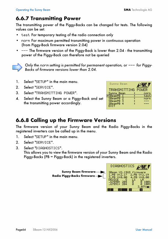
6.6.6 Calling up the exact Battery LevelYou can call up the exact charge level of the batteries in volts in the menu.1. Select "SETUP" in the main menu.2. Select "SERVICE".3. Select "DIAGNOSTICS". You can view the exact charge level of the batteries in
volts in front of the battery symbol (see figure below).
If the communication quality is less than 30 %, check the antenna alignment asdescribed in chapter “Calling up the Communication Quality" on page 63.
3.PB V:0.00 4.PB V:0.00
SBeam V2.19US firmware
DIAGNOSTICS
1.PB V:2.17 2.PB V:2.19
DEVICE S LS LR .67890: 204 0 0 100%
3.07V
Communication quality of the inverters .67891: 204 0 0 100%
3.PB V:0.00 4.PB V:0.00
Charge level of the batteries
SBeam V2.19US firmware
DIAGNOSTICS
1.PB V:2.17 2.PB V:2.19
DEVICE S LS LR .67890: 204 0 0 100%
3.07V .67891: 204 0 0 100%
Operating the Sunny Beam SMA Technologie AG
Page64 SBeam-12:NX2006 User Manual
6.6.7 Transmitting PowerThe transmitting power of the Piggy-Backs can be changed for tests. The followingvalues can be set:• test For temporary testing of the radio connection only• norm For maximum permitted transmitting power in continuous operation
(from Piggy-Back firmware version 2.04)• --- The firmware version of the Piggy-Back is lower than 2.04 - the transmitting
power of the Piggy-Back can therefore not be queried
1. Select "SETUP" in the main menu.2. Select "SERVICE".3. Select "TRANSMITTING POWER".4. Select the Sunny Beam or a Piggy-Back and set
the transmitting power accordingly.
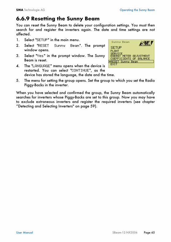
6.6.8 Calling up the Firmware VersionsThe firmware version of your Sunny Beam and the Radio Piggy-Backs in theregistered inverters can be called up in the menu.1. Select "SETUP" in the main menu.2. Select "SERVICE".3. Select "DIAGNOSTICS".
This allows you to view the firmware version of your Sunny Beam and the RadioPiggy-Backs (PB = Piggy-Back) in the registered inverters.
Only the norm setting is permitted for permanent operation, or --- for Piggy-Backs of firmware versions lower than 2.04.
TRANSMITTING POWER Sunny Beam : normSBeamPB 1 : test
SBeamPB 2 : norm
SBeamPB 3 : --- SBeamPB 4 : --- EXIT
3.PB V:0.00 4.PB V:0.00
Sunny Beam firmwareRadio Piggy-Backs firmware
SBeam V2.19US firmware
DIAGNOSTICS
1.PB V:2.17 2.PB V:2.19
DEVICE S LS LR .67890: 204 0 0 100%
3.07V .67891: 204 0 0 100%
SMA Technologie AG Operating the Sunny Beam
User Manual SBeam-12:NX2006 Page 65
6.6.9 Resetting the Sunny BeamYou can reset the Sunny Beam to delete your configuration settings. You must thensearch for and register the inverters again. The date and time settings are notaffected.1. Select "SETUP" in the main menu.2. Select "RESET Sunny Beam". The prompt
window opens.3. Select "Yes" in the prompt window. The Sunny
Beam is reset.4. The "LANGUAGE" menu opens when the device is
restarted. You can select "CONTINUE", as thedevice has stored the language, the date and the time.
5. The menu for setting the group opens. Set the group to which you set the RadioPiggy-Backs in the inverter.
When you have selected and confirmed the group, the Sunny Beam automaticallysearches for inverters whose Piggy-Backs are set to this group. Now you may haveto exclude extraneous inverters and register the required inverters (see chapter“Detecting and Selecting Inverters" on page 59).
SETUP PLANT SERVICE ENERGY METER ADJUSTMENT
COEFFICIENTS OF BALANCE
EXITRESET Sunny Beam
Operating the Sunny Beam SMA Technologie AG
Page66 SBeam-12:NX2006 User Manual
SMA Technologie AG Connecting the Device to the PC
User Manual SBeam-12:NX2006 Page 67
7 Connecting the Device to the PCYou can manage the Sunny Beam data with a PC and the SMA Sunny Data ControlSoftware. The following possibilities are available:• Saving and displaying the monthly Sunny Beam data• Parameterizing the inverters via the Sunny Beam (for qualified staff only)• Sending system data to the Sunny Portal in the internet
The Sunny Portal allows you to store your system data long-term, display them andcompare them with other PV systems. See www.SunnyPortal.com for moreinformation on the Sunny Portal.
Connecting the Device to the PC SMA Technologie AG
Page68 SBeam-12:NX2006 User Manual
7.1 Detecting Sunny Beam with Sunny Data ControlIn order to detect the Sunny Beam with Sunny Data Control you need:• a PC with a USB connection• the enclosed SMA-CD with Sunny Data Control Software and USB driver
(available also from the download area at www.SMA.de)• the Sunny Beam and the enclosed USB connecting cable
First, you install the USB driver and the Sunny Data Control software in order to beable to detect the Sunny Beam with Sunny Data Control.
7.1.1 Installing the USB DriverOperating systems supported by the USB driver: WINDOWS 2000/XP.1. Switch on your PC and wait until the operating system has booted up
completely. Once you have installed the USB driver, connect the Sunny Beam (in the normalview) to the PC using the USB connecting cable and install the Sunny DataControl as described in chapter “Installing Sunny Data Control" on page 69.
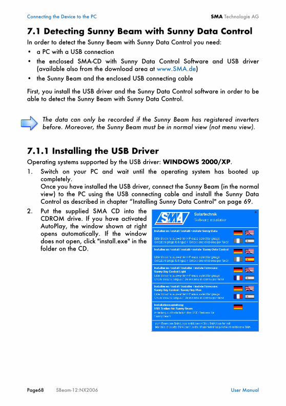
2. Put the supplied SMA CD into theCDROM drive. If you have activatedAutoPlay, the window shown at rightopens automatically. If the windowdoes not open, click "install.exe" in thefolder on the CD.
The data can only be recorded if the Sunny Beam has registered invertersbefore. Moreover, the Sunny Beam must be in normal view (not menu view).
SMA Technologie AG Connecting the Device to the PC
User Manual SBeam-12:NX2006 Page 69
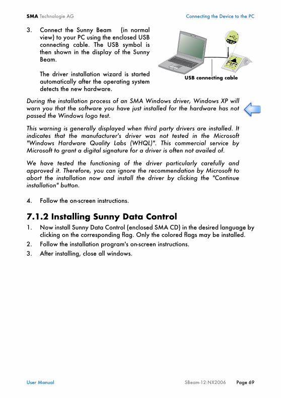
3. Connect the Sunny Beam (in normalview) to your PC using the enclosed USBconnecting cable. The USB symbol isthen shown in the display of the SunnyBeam.
The driver installation wizard is startedautomatically after the operating systemdetects the new hardware.
4. Follow the on-screen instructions.
7.1.2 Installing Sunny Data Control1. Now install Sunny Data Control (enclosed SMA CD) in the desired language by
clicking on the corresponding flag. Only the colored flags may be installed.2. Follow the installation program's on-screen instructions.3. After installing, close all windows.
During the installation process of an SMA Windows driver, Windows XP willwarn you that the software you have just installed for the hardware has notpassed the Windows logo test.
This warning is generally displayed when third party drivers are installed. Itindicates that the manufacturer's driver was not tested in the Microsoft"Windows Hardware Quality Labs (WHQL)". This commercial service byMicrosoft to grant a digital signature for a driver is often not availed of.
We have tested the functioning of the driver particularly carefully andapproved it. Therefore, you can ignore the recommendation by Microsoft toabort the installation now and install the driver by clicking the "Continueinstallation" button.
USB connecting cable
Connecting the Device to the PC SMA Technologie AG
Page70 SBeam-12:NX2006 User Manual
7.1.3 Setting up Sunny Data Control1. Start Sunny Data Control.2. Open the "Setup" menu in Sunny Data Control.3. Under "connection via", set "SunnyBeamUSB".4. Open the "Detect" menu and click on "detect". 5. Now you can drag the Sunny Beam to the right part of the window in the the
current value display using the "drag and drop" function in order to request themeasurement values.
In the Sunny Data Control Help (on the CD or in the download area ofwww.SMA.de) there is further information on Sunny Data Control and how you cansend data to the Sunny Portal in the internet.
SMA Technologie AG Connecting the Device to the PC
User Manual SBeam-12:NX2006 Page 71
7.2 Parameterizing the Inverters
Inverter parameterization is described in the Sunny Data Control Help. The device isparameterized via a radio connection between the Sunny Beam and the inverters.Before you can parameterize the device, you must first detect the Sunny Beam withthe SMA Sunny Data Control software (see chapter “Detecting Sunny Beam withSunny Data Control" on page 68).
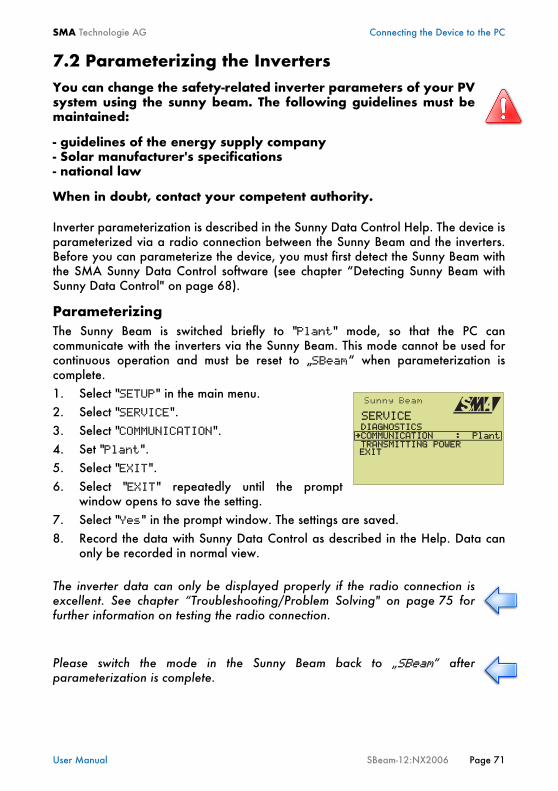
ParameterizingThe Sunny Beam is switched briefly to "Plant" mode, so that the PC cancommunicate with the inverters via the Sunny Beam. This mode cannot be used forcontinuous operation and must be reset to „SBeam“ when parameterization iscomplete.1. Select "SETUP" in the main menu.2. Select "SERVICE".3. Select "COMMUNICATION".4. Set "Plant".5. Select "EXIT".6. Select "EXIT" repeatedly until the prompt
window opens to save the setting.7. Select "Yes" in the prompt window. The settings are saved.8. Record the data with Sunny Data Control as described in the Help. Data can
only be recorded in normal view.
You can change the safety-related inverter parameters of your PVsystem using the sunny beam. The following guidelines must bemaintained:
- guidelines of the energy supply company- Solar manufacturer's specifications- national law
When in doubt, contact your competent authority.
The inverter data can only be displayed properly if the radio connection isexcellent. See chapter “Troubleshooting/Problem Solving" on page 75 forfurther information on testing the radio connection.
Please switch the mode in the Sunny Beam back to „SBeam“ afterparameterization is complete.
SERVICE DIAGNOSTICSCOMMUNICATION : Plant
TRANSMITTING POWER
EXIT
Connecting the Device to the PC SMA Technologie AG
Page72 SBeam-12:NX2006 User Manual
7.3 Updating the FirmwareYou can call up the firmware version of your Sunny Beam via the menu, as describedin section “Calling up the Firmware Versions" on page 64.To update the Sunny Beam Firmware, you require:• a PC with a USB connection and internet connection• the supplied SMA CD for the USB driver
(also available in the download area at www.SMA.de)• the Sunny Beam and the enclosed USB connecting cable• the latest firmware update (available from the download area at www.SMA.de)
The latest Sunny Beam user manual is also available from the download area atwww.SMA.de.
Installing the USB driver1. Install the USB driver as described in chapter “Installing the USB Driver" on
page 68.Once you have installed the USB driver, connect the Sunny Beam (in the normalview) to the PC using the USB connecting cable. Then set the Sunny Beam to theupdate mode as described below.
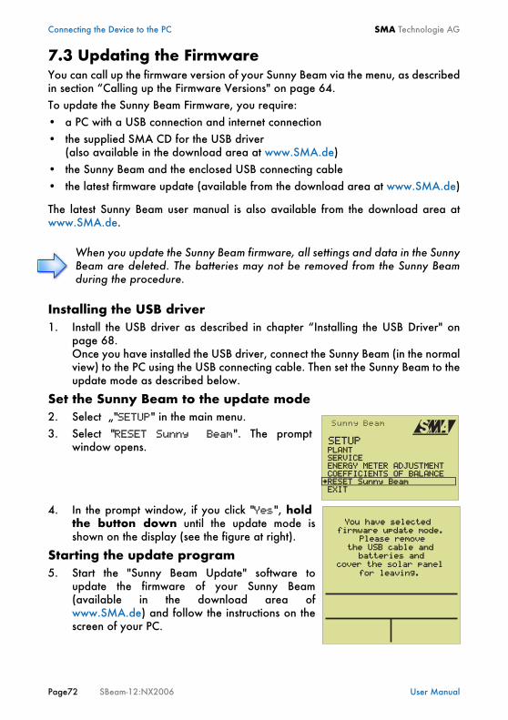
Set the Sunny Beam to the update mode2. Select „"SETUP" in the main menu.3. Select "RESET Sunny Beam". The prompt
window opens.
4. In the prompt window, if you click "Yes", holdthe button down until the update mode isshown on the display (see the figure at right).
Starting the update program5. Start the "Sunny Beam Update" software to
update the firmware of your Sunny Beam(available in the download area ofwww.SMA.de) and follow the instructions on thescreen of your PC.
When you update the Sunny Beam firmware, all settings and data in the SunnyBeam are deleted. The batteries may not be removed from the Sunny Beamduring the procedure.
SETUP PLANT SERVICE ENERGY METER ADJUSTMENT
COEFFICIENTS OF BALANCE
EXITRESET Sunny Beam
You have selected
firmware update mode.
Please remove
the USB cable and
batteries and
cover the solar panel
for leaving.

SMA Technologie AG Connecting the Device to the PC
User Manual SBeam-12:NX2006 Page 73
If the USB connector is removed during the update procedure, or the update isotherwise interrupted, it may not be possible to reset the Sunny Beam to its normaloperating mode.1. Remove the batteries and insert them again while pressing the rotating push
button.2. Connect your Sunny Beam to the PC again using the USB connecting cable and
restart the update procedure.If the Sunny Beam still does not indicate normal operation, contact the Sunny BoyHotline (see chapter “Contact" on page 89).

Connecting the Device to the PC SMA Technologie AG
Page74 SBeam-12:NX2006 User Manual
SMA Technologie AG Troubleshooting/Problem Solving
User Manual SBeam-12:NX2006 Page 75
8 Troubleshooting/Problem Solving
8.1 Radio Connection
All work on the inverters may only be performed by qualifiedelectricians! Please follow all safety instructions contained in theinverter documentation!
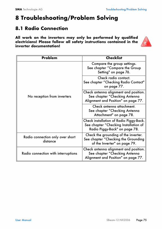
Problem Checklist
No reception from inverters
Compare the group settings.See chapter “Compare the Group
Setting" on page 76.
Check radio contact.See chapter “Checking Radio Contact"
on page 77.
Check antenna alignment and position.See chapter “Checking Antenna
Alignment and Position" on page 77.
Check antenna attachment.See chapter “Checking Antenna
Attachment" on page 78.
Check installation of Radio Piggy-Back.See chapter “Checking Installation of
Radio Piggy-Back" on page 78.
Radio connection only over short distance
Check the grounding of the inverter.See chapter “Checking the Grounding
of the Inverter" on page 79.
Radio connection with interruptionsCheck antenna alignment and position.
See chapter “Checking Antenna Alignment and Position" on page 77.

Troubleshooting/Problem Solving SMA Technologie AG
Page76 SBeam-12:NX2006 User Manual
8.1.1 Compare the Group SettingThe group set for the Radio Piggy-Back must match the group set in the Sunny Beamfor the Sunny Beam to detect the inverter. The Radio Piggy-Backs and the SunnyBeam are set to group 1 by default. If more than one device is to be detected (max.four), they must all be set to the same group.1. Check the group setting for the Radio Piggy-Back as described in chapter “DIP
switch setting on the Radio Piggy-Back" on page 25 (permitted only for qualifiedelectricians).
2. Check the group setting for the Sunny Beam asfollows: Select "SETUP" in the main menu.
3. Select "PLANT". 4. Select "GROUP".5. Compare the group setting of your Sunny Beam
in the menu with the DIP switch setting on theRadio Piggy-Back.
6. If the Sunny Beam is not set to the same group as the Piggy-Backs, rotate thebutton and set the corresponding group (0 to 15).
7. Select "EXIT" repeatedly until the prompt window opens to save the setting.8. Select "Yes" in the prompt window. The settings are saved.
Radio Piggy-Back

SMA Technologie AG Troubleshooting/Problem Solving
User Manual SBeam-12:NX2006 Page 77
8.1.2 Checking Radio ContactProceed as follows to check whether the Sunny Beam has radio contact to theinverters:1. Position the Sunny Beam approx. three meters (not less) away from the inverter
(sight contact, same height).2. Select "VIEW OPTIONS" in the main menu of the Sunny Beam.3. Select "DATA REQUEST FREQ.".4. Set the data request frequency to the maximum frequency (the minimum
selectable interval).
5. Restart inverter detection as described in chapter “Detecting and SelectingInverters" on page 59.
6. If the Sunny Beam has no radio connection even when 3m away from theinverter, the radio communication may be subject to interference from otherdevices. Try to position other radio devices outside the range of the SunnyBeam.
8.1.3 Checking Antenna Alignment and Position1. Turn the Sunny Beam so that the internal antenna is optimally adjusted.2. Check whether the antenna alignment is suitable for the radio gap to be bridged
between the Sunny Beam and the inverters (see chapter “Basic Information onRadio Transfer" on page 36).
Select a location for the Sunny Beam that is closer to the inverter, taking into accountthe installation site requirements (see “Mounting the Sunny Beam" on page 17).
After finishing this test, it is important that you set the data request frequencyback to minimum 15 seconds. Lower values (under 15 seconds) should only beset for commissioning purposes (testing the radio connection) and not long-term.
The lower the data request frequency value, the higher the Sunny Beam'senergy consumption.

Troubleshooting/Problem Solving SMA Technologie AG
Page78 SBeam-12:NX2006 User Manual
8.1.4 Checking Antenna Attachment
1. Check whether the antenna cable is securely fastened to the antenna connectionof the Radio Piggy-Back.
2. Check whether the grooved ring used to secure the PG screw fitting to theinterior of the enclosure has electrical contact to the bare metal enclosure.
Check the low resistance connection of the metallic PG screw fitting to the enclosure(PE) in the inverter (e.g. using a multimeter).
8.1.5 Checking Installation of Radio Piggy-Back
1. Check that the Radio Piggy-Back is fitted and positioned correctly in the inverter,as described in the inverter documentation (see also chapter “Installing a RadioPiggy-Back in an Inverter" on page 19, of the Sunny Beam user manual).
This chapter is intended solely for qualified electricians!All work on the inverters may only be performed by qualifiedelectricians! Please follow all safety instructions contained in theinverter documentation!
This chapter is intended solely for qualified electricians!All work on the inverters may only be performed by qualifiedelectricians! Please follow all safety instructions contained in theinverter documentation!
SMA Technologie AG Troubleshooting/Problem Solving
User Manual SBeam-12:NX2006 Page 79
8.1.6 Checking the Grounding of the Inverter
1. Check the grounding of the inverter as described in the inverter documentation.2. Check that the inverter's earth wire (PE) is connected to the distributor. 3. Check the quality of the building grounding.
8.2 Hatched SurfacesHatched surfaces occur in the curves if the radio connection between the Sunny Beamand the Radio Piggy-Backs is reduced. Check the radio contact (“Checking RadioContact" on page 77), the antenna attachment (“Checking Antenna Attachment" onpage 78) and the antenna alignment (“Checking Antenna Alignment and Position"on page 77).
8.3 The Display switches off completelyIf the Sunny Beam's display switches off completely (including the power indicator),this may be for the following reasons:
• The Sunny Beam automatically goes into night mode if the inverter has switcheditself off as no feed-in occurs at night. When the inverter starts to feed in again inthe morning and switches itself on, the Sunny Beam display automatically switchesitself back on as well.
• No inverter is yet registered on the Sunny Beam. Detect your inverters with theSunny Beam as described in chapter “Detecting and Selecting Inverters" onpage 59.
• The batteries are to weak or too old. Recharge the batteries as described inchapter “Battery Symbol/Charging the Batteries" on page 48. If the battery output remains low in spite of this, replace the two batteries with twoof the same type (SMA order number: SBEAM-BAT), as described in section“Replacing the Batteries" on page 81 .
This chapter is intended solely for qualified electricians!All work on the inverters may only be performed by qualifiedelectricians! Please follow all safety instructions contained in theinverter documentation!
One indication of a missing PE, is if a radio connection is only possible overrelatively short distances.
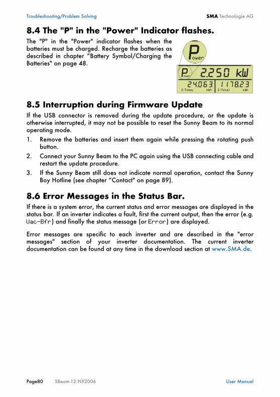
Troubleshooting/Problem Solving SMA Technologie AG
Page80 SBeam-12:NX2006 User Manual
8.4 The "P" in the "Power" Indicator flashes.The "P" in the "Power" indicator flashes when thebatteries must be charged. Recharge the batteries asdescribed in chapter “Battery Symbol/Charging theBatteries" on page 48.
8.5 Interruption during Firmware UpdateIf the USB connector is removed during the update procedure, or the update isotherwise interrupted, it may not be possible to reset the Sunny Beam to its normaloperating mode.1. Remove the batteries and insert them again while pressing the rotating push
button.2. Connect your Sunny Beam to the PC again using the USB connecting cable and
restart the update procedure.3. If the Sunny Beam still does not indicate normal operation, contact the Sunny
Boy Hotline (see chapter “Contact" on page 89).
8.6 Error Messages in the Status Bar.If there is a system error, the current status and error messages are displayed in thestatus bar. If an inverter indicates a fault, first the current output, then the error (e.g.Uac-Bfr) and finally the status message (or Error) are displayed.
Error messages are specific to each inverter and are described in the "errormessages" section of your inverter documentation. The current inverterdocumentation can be found at any time in the download section at www.SMA.de.
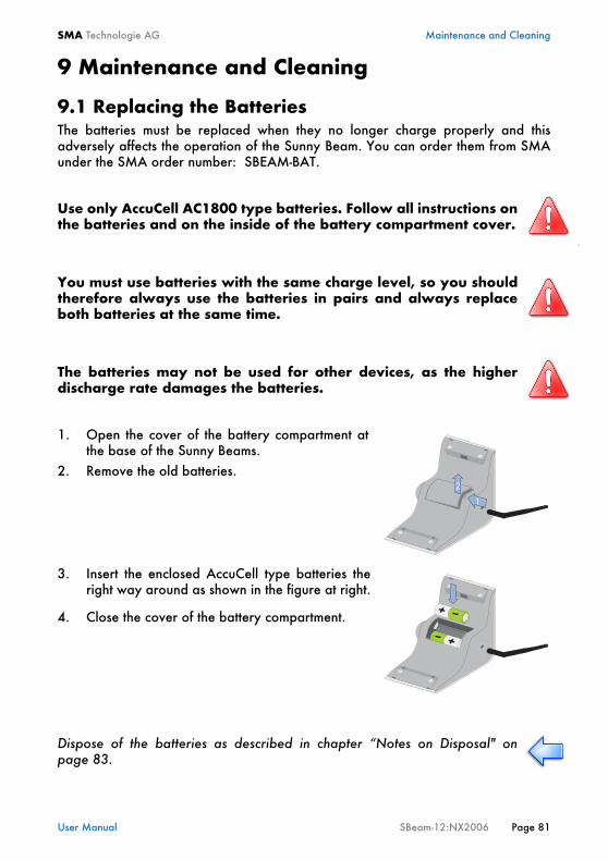
SMA Technologie AG Maintenance and Cleaning
User Manual SBeam-12:NX2006 Page 81
9 Maintenance and Cleaning
9.1 Replacing the BatteriesThe batteries must be replaced when they no longer charge properly and thisadversely affects the operation of the Sunny Beam. You can order them from SMAunder the SMA order number: SBEAM-BAT.
1. Open the cover of the battery compartment atthe base of the Sunny Beams.
2. Remove the old batteries.
3. Insert the enclosed AccuCell type batteries theright way around as shown in the figure at right.
4. Close the cover of the battery compartment.
Use only AccuCell AC1800 type batteries. Follow all instructions onthe batteries and on the inside of the battery compartment cover.
s
You must use batteries with the same charge level, so you shouldtherefore always use the batteries in pairs and always replaceboth batteries at the same time.
The batteries may not be used for other devices, as the higherdischarge rate damages the batteries.
Dispose of the batteries as described in chapter “Notes on Disposal" onpage 83.
Maintenance and Cleaning SMA Technologie AG
Page82 SBeam-12:NX2006 User Manual
9.2 CleaningTo clean your Sunny Beam, use a mild, non-corrosive cleaning agent or a damp cloth.Make sure that the cloth is made of scratch-free material so the surface of the SunnyBeam will not be damaged.
SMA Technologie AG Disposal
User Manual SBeam-12:NX2006 Page 83
10 Disposal
10.1 DecommissioningRemove the batteries as described in chapter “Replacing the Batteries" on page 81.
10.2 Notes on Disposal
10.2.1 BatteriesThe AccuCell type batteries are environmentally friendly alkali-manganese cells(without lead, cadmium or mercury). However, they must still be disposed ofcorrectly. Please dispose of the batteries correctly. You can order them from SMAunder the SMA order number: SBEAM-BAT.
10.2.2 Sunny BeamPlease dispose of the Sunny Beam at an authorized disposal company.
10.3 Packaging for ShipmentWhen returning the device to us, please be sure to use packaging which adequatelyprotects the device from damage during transport (if possible, the original packing).
Disposal SMA Technologie AG
Page84 SBeam-12:NX2006 User Manual
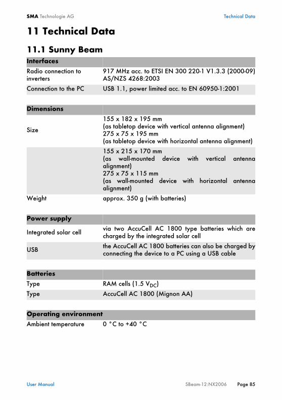
SMA Technologie AG Technical Data
User Manual SBeam-12:NX2006 Page 85
11 Technical Data
11.1 Sunny BeamInterfaces
Radio connection toinverters
917 MHz acc. to ETSI EN 300 220-1 V1.3.3 (2000-09)AS/NZS 4268:2003
Connection to the PC USB 1.1, power limited acc. to EN 60950-1:2001
Dimensions
Size
155 x 182 x 195 mm (as tabletop device with vertical antenna alignment)275 x 75 x 195 mm (as tabletop device with horizontal antenna alignment)
155 x 215 x 170 mm (as wall-mounted device with vertical antennaalignment)275 x 75 x 115 mm(as wall-mounted device with horizontal antennaalignment)
Weight approx. 350 g (with batteries)
Power supply
Integrated solar cell via two AccuCell AC 1800 type batteries which arecharged by the integrated solar cell
USB the AccuCell AC 1800 batteries can also be charged byconnecting the device to a PC using a USB cable
Batteries
Type RAM cells (1.5 VDC)
Type AccuCell AC 1800 (Mignon AA)
Operating environment
Ambient temperature 0 °C to +40 °C
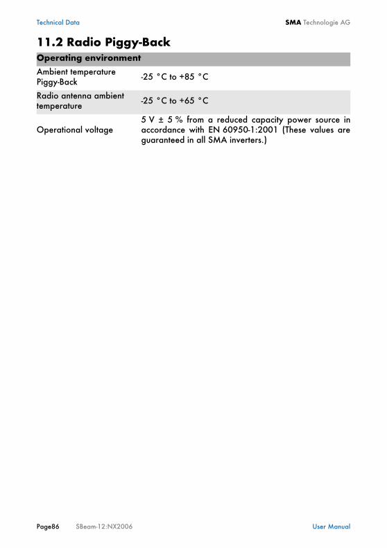
Technical Data SMA Technologie AG
Page86 SBeam-12:NX2006 User Manual
11.2 Radio Piggy-BackOperating environment
Ambient temperaturePiggy-Back -25 °C to +85 °C
Radio antenna ambienttemperature -25 °C to +65 °C
Operational voltage5 V ± 5 % from a reduced capacity power source inaccordance with EN 60950-1:2001 (These values areguaranteed in all SMA inverters.)

SMA Technologie AG Technical Data
User Manual SBeam-12:NX2006 Page 87
11.3 Declaration of Conformity
Product: Sunny Beam U, SBEAMPB2 - 01 included in BEAMPBU - NR
We declare that the above specified devices are compliant with the Australian standards, interms of the design and the version fabricated by SMA.
The devices are compliant with the following standards:
AS/NZS 4268:2003Amendment No. 1 to AS/NZS 4268:2003ETSI EN 300220-1 V1.3.1 (2000 - 09)FCC CFR 47, part 17
SBEA
M-A
US-
11:B
E180
6
Declaration of Conformity
Niestetal, 04.05.2006
SMA Technologie AG
Peter Drews(Board of Manager)
SMA Technologie AGHannoversche Straße 1-5 34266 NiestetalTel. +49 561 9522 – 0Fax +49 561 9522 – [email protected]
for Data Logging Equipment
Technical Data SMA Technologie AG
Page88 SBeam-12:NX2006 User Manual
SMA Technologie AG Contact
User Manual SBeam-12:NX2006 Page 89
12 ContactIf you have any questions or queries, please contact us. A team of qualified engineersand technicians is at your disposal.
Help us to help you by having the following information ready when you call us:• Type of Sunny Beam (see chapter “Identifying the Sunny Beam" on page 13)• Firmware of the Sunny Beam and the Radio Piggy-Backs (see chapter Table 2.5
on page 13)• Type of inverter and serial number (see inverter documentation)
Address:
SMA Technologie AGHannoversche Str. 1-534266 NiestetalGermany
Tel. (+49) 5 61 95 22 – 499Fax (+49) 5 61 95 22 – 4699www.SMA.de
Contact SMA Technologie AG
Page90 SBeam-12:NX2006 User Manual
12.1 Suggested ImprovementsThe following e-mail address can be used to suggest improvements to thisdocumentation:[email protected].
SMA Technologie AG Contact
User Manual SBeam-12:NX2006 Page 91
Legal Restrictions SMA Technologie AG
Page 92 SBeam-12:NX2006 User Manual
The information contained in this document is the property of SMA Technologie AG. Publishing its content,either partially or in full, requires the written permision of SMA Technologie AG. Any internal companycopying of the document for the purposes of evaluating the product or its correct implementation is allowedand does not require permission.
Exclusion of liabilityThe general terms and conditions of delivery of SMA Technologie AG shall apply.The content of these documents is continually checked and amended, where necessary. However,discrepancies cannot be excluded. No guarantee is made for the completeness of these documents. Thelatest version is available on the Internet at www.SMA.de or from the usual sales channels.Guarantee or liability claims for damages of any kind are exlcuded if they are caused by one or more of thefollowing:• Improper or inappropriate use of the product• Operating the product in an unintended environment• Operating the product whilst ignoring relevant, statutory safety regulations in the deployment location• Ignoring safety warnings and instructions contained in all documents relevant to the product• Operating the product under incorrect safety or protection conditions• Altering the product or supplied software without authority• The product malfunctions due to operating attached or neighboring devices beyond statutory limit values• In case of unforeseen calamity or force majeure
Software licensingThe use of supplied software produced by SMA Technologie AG is subject to the following conditions:This software may be copied for internal company purposes and may be installed on any number ofcomputers. Supplied source codes may be changed or adapted for internal company purposes on your ownresponsibility. Drivers may also be transferred to other operating systems. Source codes may only bepublished with the written permission of SMA Technologie AG. Sub-licensing of software is not permissible.Limitation of liability: SMA Technologie AG rejects any liability for direct or indirect damages arising fromthe use of software developed by SMA Technologie AG. This also applies to the provision or non-provisionof support activities.Supplied software not developed by SMA Technologie AG is subject to the respective licensing and liabilityagreements of the manufacturer.
TrademarksAll trademarks are recognized even if these are not marked separately. Missing designations do not meanthat a product or brand is not a registered trademark. SMA Technologie AGHannoversche Straße 1-534266 NiestetalGermanyTel. +49 561 9522-0Fax +49 561 9522-100www.SMA.deE-mail: [email protected]© 2005 SMA Technologie AG. All rights reserved.


www.SMA.deSales Solar Technology
SMA Technologie AGHannoversche Strasse 1–534266 Niestetal, GermanyTel. : +49 561 9522 4000Fax: +49 561 9522 4040E-Mail: [email protected]: +800 SUNNYBOYFreecall: +800 78669269
Innovation in Systems Technology for the Success of Photovoltaics