system for reading the status and for controlling the power supplies
TRANSCRIPT

US005949974A ‘
United States Patent 119] Ewing et al.
5,949,974 Sep. 7, 1999
[11] Patent Number:
[45] Date of Patent:
[54]
[76]
[21]
[22]
[51] [52]
[53]
SYSTEM FOR READING THE STATUS AND 5.585.678 12/1996 Dijk et a]. ............................. .. 307/112 FOR CONTROLLING THE POWER $652,893 7/1997 Ben-Meir et a1. . 995/150 02 SUPPLIES 0F APPLIANCES CONNECTED 5.761.084 6/1998 Edwards .......... .. 364152828 T0 COMPUTER NETWORKS 5,781,434 7/1998 Tobita et a]. .......................... .. 364/184
0 _ OTHER PUBLICATIONS Inventors: Carrel! W. Ewing. 585 Washington.
palo Alto‘ Cant 94301; Andrew J. W. Richard Stevens. “TCP/IP Illustrated. vol. 1 —The Cleveland. 12467 Creek View 01.. San Pr9I9¢9ls”- pp- 359—361- 1994 Mal-um Cami 95046 Michael Slater. “Microprocessor-Based Design-A Com—
prehensive Guide to Hardware Design". pp. 19-24. 1989. Peter Drake “Usin SNMP to Mana e Networks” . A 1. N .1 08/685 36 ~ g g - PP
pp 0 A 2/1-2/4. 1991. F 'l d: . , . 1 6 Jul 23 1996 Primary Examiner—Zarn1 Maung Int. Cl.6 ............................. .. G06F 15/16; G06F 1/26 Assistant Examiner—Andrew Caldwell US. Cl. .............................. .. 395/200.32: 395/200.53; Alwmey. Agent, or Firm—Richard B. Main
_ 3977-50-03 [57] ABSTRACT Field of Search ................................... .. 340/644. 646.
340/31001. 825.5; 395/20032. 200.53. A SNMP network comprises a power manager with :1 SNMP 200.54 agent in TCP/IP communication over a network with a
SNMP network manager. The power manager is connected References Cited to control several intelligent power modules each able to
Us‘ PATENT DOCUMENTS independently control the on/olf power to several inter > networking dev1ces 1n an equipment rack at a common
4.101.878 7/1978 Shimizu et al. ................. .. 340/31001 remote node. e.g.. a point-of-presence site. Power-0n and 4.495.568 1/1985 Gilbert et a1. 395/1822 load sensors Within each intelligent power module are able 4,709,318 11/1987 Gepharl 6t ......................... .. 363/37 [0 l'cpon the power status of each intcpngtworking dcvicg to 4.780,? 14 10/1988 Moustakas et a1. ............... .. 340/8255 the SNMP network manager with MR; variables in response
1:; a1‘ to GET commands. The SNMP network manager is further 5‘ 412’6“ 5,1995 Youislgn ‘370/365 able to reboot each inter-networking device by cycling the ‘514811136 [/1998 Brown at a], " '5'951750‘08 power onlo?’ to its respective intelligent power module with 5:485:576 1/1996 Fee et al. .... .. .: 395/18509 the SET command Pmvided i" convcmlional SNMP ma" 5.495.607 2/1996 PIS/e110 813]. . .... .. 701/10 agcmcm applications
5506573 4/1996 Ewing et a1. . 340/644 5.561.769 10/1996 Kumar et al. .................... .. 395000.32 12 Claims, 4 Drawing Sheets
10 e‘
/\ 14 5° IE" ( TCP/IP
*Elqa POP POP 24
SNMP '\ SNMP 22 SNMP ‘/ 20 '\ a ] manager 12 99"“ agent 15 1a
host El ‘9 “—2 E2]
25 power 46 mgr ‘
ILP w % 36
SNMP [- 31 agent 32
err 30
UPS 26
ulrlrty power
Sheet 2 of 4 US. Patent Sep. 7, 1999
2 Fig.
100 "1 i apply a series of alternating current (AC) voltage pulses
to an appliance with an on/otf switch that are synchronized
to a source of AC power
it
5,949,974
102
"104 sense the presence of any series of
AC current pulses that result it the appliance switch is closed
in step 104 to determine if they resulted from the application
of the AC voltage in step 102
analyze any AC current pulses detected (‘106
L output an on/off status indication
for the appliance switch 108
l

US. Patent Sep. 7, 1999 Sheet 4 0f 4 5,949,974
Flg._4 +5 VDC
(214
f 246 +12 VDC
70 VAC ,
“ O I power
' supp'y 245
Eref _ J __
+ neutraLin (244 neutraLout O I "v I a
5 Rs 5
....................................................................................................... _¢
236
V_SENS
5.949.974 1
SYSTEM FOR READING THE STATUS AND FOR CONTROLLING THE POWER
SUPPLIES OF APPLIANCES CONNECTED TO COMPUTER NETWORKS
BACKGROUND OF THE INVENTION
1. Field of the Invention The invention relates generally to automatic power con
trol and more particularly to remote control methods and devices to maintain computer network system availability.
2. Description of the Prior Art Enterprise networks exist to support large world-wide
organizations and depend on a combination of technologies. e.g.. data communications. inter-networking equipment (frame relay controllers. asynchronous transfer mode (ATM) switches. routers. integrated services digital network (ISDN) controllers. application servers). and network management application software. Such enterprise networks can be used to support a large company‘s branch o?ices throughout the world. and. as such. these networks have become mission critical to the functioning of such organizations. Masses of information are routinely expected to be exchanged. and such information exchanges are necessary to carry on the daily business of modern organizations. For example. some international banks have thousands of branch of?ces placed throughout Europe. Asia and the United States that each critically depend on their ability to communicate banking transactions quickly and e?iciently with one another and headquarters. A typical enterprise network uses building blocks of
router and frame relay inter-networking devices mounted in equipment racks. Such equipment racks are distributed to remote point of presence (POP) locations in the particular network. Each equipment rack can include frame relay controllers. routers. ISDN controllers. servers and modems. etc.. each of which are connected to one or more power sources. The value of POP equipment can range from $200000 to $500.000. and the number of individual devices can exceed a thousand.
Many enterprises rely on an uninterruptable power supply (UPS) to keep their inter-networking devices operational. Many inter-networking devices are typically connected to a single UPS. and this sets up a problem. When an individual router locks up. the router’s power cannot be individually cycled on and off externally at the UPS because it is connected to a multiple power outlet. The recovery action choices available to the network control center operator thus do not include being able to reinitialize the individual equipment through a power interruption reset. The network operator could command the UPS to power cycle. but that would reset all the other attached devices that were osten sibly operating normally and carrying other network tra?ic. Another option is to dispatch someone to the remote location to reset the locked-up device. Neither choice is an attractive solution.
In large organizations that have come to depend heavily on enterprise networks. great pressures develop to control costs and thus to improve pro?ts. Organizational down sizing has been used throughout the corporate world to reduce non-network costs. and that usually translates to fewer technical people available in the right places to support large and complex in-house global networks. Such reduced repair staffs now rely on a combination of central ized network management tools and third-party maintenance organizations to service their remote POP sites. The costs associated with dispatching third-party maintenance techni
10
25
30
35
45
50
55
65
2 cians is very high. and the dispatch and travel delay times can humble the business operations over a wide area for what seems an eternity.
Global communication network operators. located at a few centralized network management centers. are relying more and more on automated network management appli cations to analyze. process. display and support their net works. An increasing number of network management soft ware applications are being marketed that use open-system standardized protocols. Particular network application tool software is available to report lists of the inter-networking devices. by location. and can issue uouble lists and keep track of software versions and releases. New simple network management protocol (SNMP) applications are convention ally used to issue alarms to central management consoles when remote inter-networking devices fail. One such SNMP network management application is
marketed by Hewlett-Packard. HP OPENVIEW is a family of network and system management tools and services for local and wide area multivendor networks. OPENVIEW is a management platform that provides application developers and users with the ability to manage multivendor networks and expand their distributed computing environments. OPENVIEW allows network operation centers to build an intelligent hierarchical network management application. and uses open standards such as SNMP. user datagrarn protocol (UDP). and the now ubiquitous transmission con trol protocol/internet protocol (T CP/IP). Because OPEN VIEW is built on open system standards. global communi cation network operators can easily integrate the various inter-networking equipment nodes into a managed environ ment operated by strategically located network consoles.
In order to provide a reliable computing environment. a robust and active process for problem resolution must be in place. OPENVIEW allows the de?nition of thresholds and monitoring intervals. and the interception of network. system. database. and application-messages and alerts. Once a threshold value is- exceeded. intelligent agents can run a pre-defined automatic action and/or generate and send a message to alert an operator on a central management console. Messages can also be forwarded to a pager or trouble-ticketing application. To help focus on the most critical problems. a message browser window is used to display six severity levels for incoming problems and events. e.g.. ranging from stable to critical. An integrated history database is provided for auditing and analyzing system and network activities. for identifying trends and for anticipating problems before they occur. Activity displays and reports can be customized by the users.
Prior art SNMP network management uses embedded microprocessors in almost every inter-networking device to support two-way inter-computer communications with TCP/ IP. of which SNMP is a member of the TCP/IP protocol suite. SNMP is conventionally used to send messages between management client nodes and agent nodes. Man agement information blocks (MIBs) are used for statistic counters. port status. and other information about routers and other network devices. GET and SET commands are issued from management consoles and operate on particular MlB variables for the equipment nodes. Such commands allow network management functions to be carried out between client equipment nodes and management agent nodes. SNMP is an application protocol for network manage
ment services in the internet protocol suite. SNMP has been adopted by numerous network equipment vendors as their

5.949.974 3
main or secondary management interface. SNMP de?nes a client/server relationship. wherein the client program. a “network manager". makes virtual connections to a server program. an “SNMP agent”. on a remote network device. The data base controlled by the SNMP agent is the SNMP management information base. and is a standard set of statistical and control values. SNMP and private MlIBs allow the extension of standard values with values speci?c to a particular agent. Directives issued by the network manager client to an SNMP agent comprise SNMP variable identi?ers. e. g.. MIB object identi?ers or MIB variables. and instructions to either GET the value for the identi?er. or SET the identi?er to a new value. Thus private MIB variables allow SNMP agents to be customized for speci?c devices. e.g.. network bridges. gateways. and routers. The de?nitions of MB variables being supported by particular agents are located in descriptor ?les. typically written in abstract syn tax notation (ASN.1) format. The de?nitions are available to network management client programs. SNMP enjoys widespread popularity. and SNMP agents
are available for network devices including computers. bridges. modems. and printers. Such universal support pro motes interoperability. The SNMP management protocol is flexible and extensible. SNMP agents can incorporate device speci?c data. Mechanisms such as ASN.1 ?les allow the upgrading of network management client programs to inter face with special agent capabilities. Thus SNMP can take on numerous jobs speci?c to device classes such as printers. routers. and bridges. A standard mechanism of network control and monitoring is thus possible.
Unfortunately. SNMP is a complicated protocol to implement. due to complex encoding rules. and it is not a particularly e?icient protocol. Bandwidth is often wasted with needless information. such as the SNMP version that is to be transmitted in every SNMP message. and multiple length and data descriptors scattered throughout each mes sage. SNMP variables are identi?ed as byte strings. where each byte corresponds to a particular node in the MIB database. Such identi?cation leads to needlessly large data handles that can consume substantial parts of each SNMP message. Most vendors implement network managers thinking a
user’s primary interest is in the data associated with par ticular network devices. But such data is easily acquired by other means. e.g.. “netstat” and “rsh” UNIX programs. The important information about the network includes the dif ferences between devices. besides their current states. SNMP atfords a good mechanism for rapidly processing such differences on large networks. since SNMP avoids the processing burden of remote login and execution. Network management applications can thus monitor the
health of every part of a global communications network and can be set to communicate alarms to a central management console. Current network management applications do an adequate job of informing central management consoles about the health of various nodes in the network and the alarms they issue when a node is failing are useful.
Conventional SNMP network management technologies do not provide su?icient information related to the nodes’ electrical power status. A new technology is needed that can be simply and inexpensively added to client equipment nodes for SNMP reporting of the electrical power status of the node. For example. in a router based network with SNMP support. prior art individual routers can use SNMP to issue an alarm to me management console. But the console operator would know only that the router is failing. A GET
5
15
20
25
35
45
55
65
4 command can be issued to the router node to determine if the counter and buffer thresholds limits were exceeded and caused a router to lock-up. However. the console operator does not have any information about the electrical power status to the router. e.g.. has the router power switch been moved to the OFF position or has the switch been acciden tally turned OFF? The electrical power source could have failed. the power cable connection become loose. or a technician may have accidentally removed the router from a rack.
SUNIMARY OF THE PRESENT INVENTION
It is therefore an object of the present invention to provide a system and method for providing power supply status and control in network nodes at geographically distant locations.
It is another object of the present invention to provide a system and method for describing power supply status and control in SNMP MIB variables between network nodes and a central network management console.
Brie?y. an SNMP network embodiment of the present invention comprises a power manager with an SNMP agent in TCP/IP communication over a network with an SNMP network manager. The power manager is connected to control several intelligent power modules each able to independently control the power on/olf status of several inter-networking devices in an equipment rack at a common remote node. e.g.. a point-of-presence site. Power-on and load sensors within each intelligent power module are able to report the power status of each inter-networking device to the SN MP network manager with MIB variables in response to GET commands. The SNMP network manager is further able to reboot each inter-networking device by cycling the power o?/on to its respective intelligent power module with the SET command provided in conventional SNMP man agement applications. An advantage of the present invention is that a system and
method is provided for communicating and controlling the power supply status of network nodes at geographically distant locations.
Another advantage of the present invention is that a system and method is provided for describing power supply status and control in SNMP MIB variables between network nodes and a central network management console.
A further advantage of the present invention is that a system and method is provided that allows a network console operator to investigate the functionality of the electrical power status when a router or other network device has been detected as failing. A still further advantage of the present invention is that a
system and method is provided for reducing the need for enterprise network operators to dispatch third party main tenance vendors to remote equipment rooms and POP loca tions simply to power-cycle failed inter-networking devices. The costs to dispatch such third party maintenance vendor can run from $300-$600 per call. The cost of implementing the present invention can be recaptured in less than one year. e.g.. by reducing the number of third party maintenance dispatches to remote locations.
Another advantage of the present invention is that a system and method is provided for reducing the time it takes to restore a failed inter-networking device and improving service level measures.
Another advantage of the present invention is that a system and method is provided for reducing organization losses from network downtime. Being able to immediately

5.949.974 5
power-cycle a failed server and thus return the server to operation can directly reduce the downtime loss to the organization. These and many other objects and advantages of the
present invention will no doubt become obvious to those of ordinary skill in the art after having read the following detailed description of the preferred embodiments which are illustrated in the various drawing ?gures.
IN THE DRAWINGS
FIG. 1 is a block diagram of a simple network manage ment protocol (SNMP) network embodiment of the present invention:
FIG. 2 is a ?owchart of a method of appliance power switch status detection. according to the present invention:
FIG. 3 is a schematic of a representative intelligent power module such as are included in the network of FIG. 1:
FIG. 4 is a schematic diagram of the load sensor included in the intelligent power module of FIG. 3; and
FIG. 5 is a schematic diagram of the power-on sensor included in the intelligent power module of FIG. 3.
DETAILED DESCRIPTION OF THE PREFERRED EMBODIMENTS
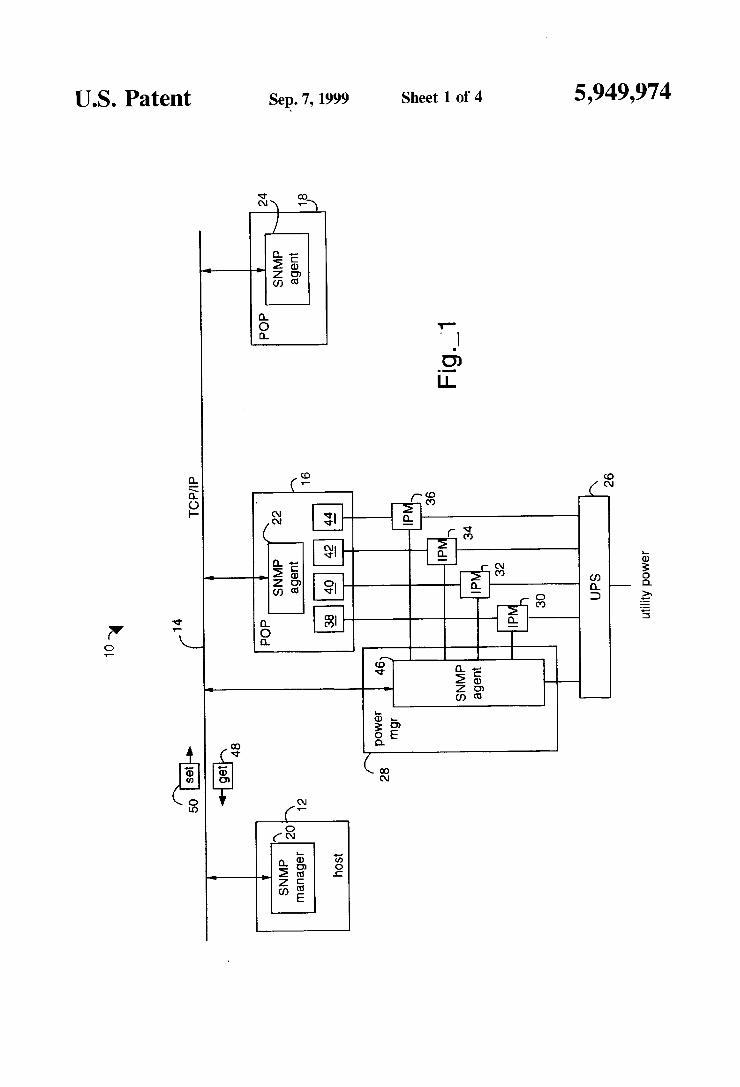
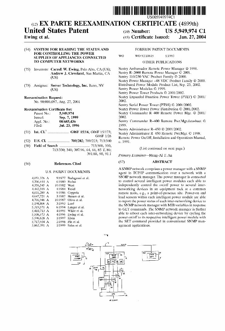
FIG. 1 illustrates a simple network management protocol (SNMP) network embodiment of the present invention. referred to herein by the general reference numeral 10. The SNMP network 10 includes a host 12 with a TCP/IP con nection 14 to a plurality of point-of-presence (POP) nodes represented by a pair of equipment racks l6 and 18. SNMP network management is provided by an SNMP manager 20 in communication with a respective pair of SNMP agents 22 and 24 at the remote nodes. The SNMP manager 20 may comprise a commercial product such as IBM NETVIEW/ 6000. HP OPENVIEW. POLYCENTER. SunNet MANAGER. Cabletron SPECTRUM. etc. Each POP node can be associated with an uninterruptable
power supply (UPS) 26 that provides operating power to a TCP/IP-addressable enterprise power manager 28 and sev eral intelligent power modules 30. 32. 34. 36 connected to corresponding inter-networking devices 38. 40. 42. 44. An SNMP agent 46 is private to the power manager 28 and does not depend'on the equipment rack 16 or its inter-networking devices 38. 40. 42. 44. The power manager 28 is connected to independently control each of the intelligent power mod ules 30. 32. 34. 36. Such control includes being able to sense the power-on and load status of each of the inter-networkin g devices 38. 40. 42. 44 and to switch power on and off to each of the inter-networking devices 38. 40. 42. 44. Such status is sensed and reported by an SNMP GEI‘ command 48 and the power switching is accomplished with an SNMP SE1" command 50 that issue from the host 12.
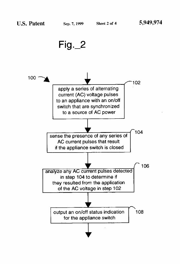
FIG. 2 shows a method of appliance power switch status detection. referred to herein by the general reference numeral 100. The method 100 comprises a step 102 applying a series of alternating current (AC) voltage pulses to an appliance with an on/off switch that are synchronized to a source of AC power. A step 104 senses the presence of any series of AC current pulses that result if the appliance switch is closed. A step 106 analyzes any AC current pulses detected in step 104 to determine if they resulted from the application of the AC voltage in step 102. A step 108 outputs an on/off status indication for the appliance switch. Method 100 does not result in the turning-on and the operation of the appliance during steps 102 or 104. and is therefore unob tru sive.
15
20
6 FIG. 3 illustrates an intelligent power module 200. similar
to intelligent power modules 30. 32. 34. 36. which may be located external or internal to devices 38. 40. 42. 44. or internal or external to the UPS 26. The intelligent power module 200 includes a power supply and clock generator 212. a load sensor 214. a power-on sensor 216. a solid-state relay 218 and a microprocessor 220. A serial input/output (I/O) connection 221 provides for communication with a controller. e.g.. power manager 28. An appliance. such as the inter-networking devices 38. 40. 42. 44. has a power on/off switch 223 that may be internal or external to the appliance represented by a network device load 224. The switch 223 may also actually comprise both internal and external switches in series. The incoming alternating current (AC) line power is applied to the intelligent power module 200 at a hot (H) terminal 225. a neutral (N) terminal 226 and a ground (G) terminal 228. The appliance has its incoming AC line power applied to a hot (H) terminal 230. a neutral (N) terminal 232 and a ground (G) terminal 234. which are respectively connected to a hot (H) terminal 236. a neutral
‘ (N) terminal 238 and a ground (G) terminal 240. A relay 242
25
35
50
55
65
allows automatic remote control by the microprocessor of power to the appliance due to its position in the incoming AC line. The load sensor 214 is such that if a current is ?owing
because switch 223 is closed. the microprocessor will receive a logic low status indication.
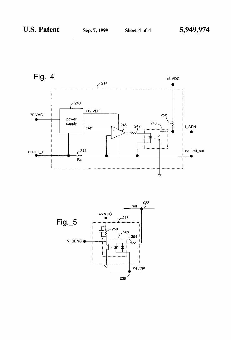
FIG. 4 represents an embodiment of the load sensor 214 included in FIG. 3. The load sensor 214 comprises a sense resistor 244 connected to a voltage comparator 245. When the voltage dropped across the sense resistor 244 exceeds a reference voltage provided by a power supply 246. the output of the voltage comparator 245 goes high. A resistor 247 couples this to an opto-isolator 248 and produces a ?ve volt digital output (I_SENS) that indicates load/no-load to the microprocessor 220.
FIG. 5 represents an embodiment of the power-on sensor 216 included in FIG. 3. The power-on sensor 216 includes an opto-isolator 252. The output of the opto-isolator 252 goes low when a sufficient voltage is dropped across a resistor 254. A ?ve volt power supply connection and a pull-up 256 provide a ?ve volt logic output (V_SENS) that indicates power/no-power to the microprocessor 220.
In operation. the device 200 senses if switch 223 is closed or open by converting AC current pulses from the power supply 212 that ?ow through the series circuit comprising the solid-state relay 218. the H-terminals 236 and 230. the switch 223. the network device load. the N-terminals 232 and 238. the load sensor 214. and return to the power supply 212. If the switch 223 is open. no such current can ?ow.
The power supply and clock generator 212 provides a ?ve volt pulse clock (CLK) to the microprocessor 220 at each zero-crossing of the incoming AC power line voltage across the H-terminal 225 and the N-terminal 226. A slightly delayed version of the clock is output by the microprocessor 220 to control the solid-state relay 218. A seventy volt AC output (7OVAC) of the power supply and clock generator 212 provides a reduced voltage AC sine wave that is approximately seventy volts RMS. The solid-state relay 218 therefore gates through the seventy volt AC waveform twice each cycle such that alternating pulses of +70 volts and —70 volts are sent through switch 223 and load sensor 214. If a current ?ows because the switch 223 is closed. a character istic pulse synchronized to the CLK signal will appear as an output from the opto-isolator m. A resistor 250 provides a pull-up to a current sense input to the microprocessor 220.
5.949.974 7
If the switch 223 is open. the characteristic pulses will not appear. An “onsense" device 252 provides isolation for a voltage sense input to the microprocessor 220. The microprocessor 220 analyzes and stores its determi
nation of whether the power is applied to the device 38-44 and whether the switch 223 is closed. Such data is thereafter useful to control the relay 242. The microprocessor 220 is programmed to control the relay 242 and to report the presence of current and voltage to the appliance through serial communication conducted over the serial IIO connec tion 221. The power manager 28 is able to read from the intelligent
power modules 30. 32. 34. 36. whether there is a proper operating voltage being supplied to the inter-networking devices 38. 40. 42. 44. and whether such loads are turned on. The power manager 28 and its SNMP agent 46 are able to report such status in response to the GET command 48. The GET command modi?es a MIB variable that is reported by the SNMP agent 46 to the SNMP manager 20. The power manager 28 is able to require the intelligent
power modules 30. 32. 34. 36. to turn the power being supplied to the inter-networking devices 38. 40. 42. 44. on or off in response to the SET command 50. Such SET commands modify the MIB variable de?ned for power on/olf. and allow independent power-cycling of each and any of the inter-networking devices 38. 40. 42. 44. Such power cycling promotes a power-up reset of the appliance. e.g.. when the SNMP agent 22 has reported a failure of the POP node 16 to the SNMP manager 20. SNMP de?nes a client/ server relationship. The client
program. network manager 20. makes virtual connections to the server program. the SNMP agent 22 and 24 on a remote network device. The database controlled by the SNMP agent is the management information base (MIB). The MIB is a standard set of statistical and control values that provides information about the attributes of devices attached to the network. SNMP allows for the extension of these standard values with values that are speci?c to a particular SNMP agent through the use of private MlBs. The use of private MIB variables allows SNMP agents to be modi?ed for a variety of devices. e.g.. bridges. hubs. routers and CSU/ DSUs. etc. SNMP operates by exchanging network infor mation through protocol data unit (PDU) messages. PDUs carry variables that have both titles and values. There are ?ve types of PDUs that SNMP uses to monitor a network. two for reading terminal data. two for setting terminal data. and one. the trap. monitoring network events. Every SNMP message consists of a variable. and every variable consists of a variable title. the integer. string data type of the variable. whether the variable is read-only or read-write. and the value of the variable. The SNMP manager 20 collects information via MIBs
about routers. hubs. bridges. concentrators. servers. switches and other inter~networking devices. When a problem at a remote node is detected. the corresponding SNMP agent issues an alarm that identifies the problem by type and node address. The SNMP manager typically sends a Telnet script to a TCP/lP-addressable enterprise power manager. The Telnet script instructs the enterprise power manager to cycle the power cycle. to recover an otherwise locked-up network device. SNMP management is not required for the enterprise power manger and the associated intelligent power modules. The intelligent power modules include normally closed relays so power is always on except when the relay is deliberately opened to trigger a power on reset and reboot. The network management application monitors the UPS and the inter-networking devices.
20
25
30
35
50
55
65
8 The load sensor and power-on sensor can be combined
such that a console operator can determine if electrical power is available to an equipment rack and to an individual inter~networking device. A relay reset located between the power source and the client equipment node supports an SNMP-type SET command that can be de?ned to open and close a relay to power-cycle the inter-networking device. Such power-cycling can clear a lockup condition and allow the device to return to normal operation via its own internal power-up reset mechanism.
A console operator can be noti?ed by conventional means that a router is failing. A determination then needs to be made that the electrical power is available to the equipment rack and to an individual inter-networking device. The next action would be to try to power-cycle an individual inter networking device to return it to operational status.
A power-on sensor 252. a load sensor 214 and a relay reset 218 can be combined in the electrical power supply con nected to the equipment rack. Once a console operator has determined both that the router is failing and that the electrical power is available to the equipment rack and to the individual inter-networking device. the next logical step can be to power-cycle the individual inter-networking device. e.g.. to return it to operational status.
Where the in-place equipment that supplies electrical power for an equipment rack cannot be modi?ed to incor porate the functions of an intelligent power module. the intelligent power module 200 can be connected in-line between the electrical power source and the equipment power receptacle. The intelligent power module provides the necessary power-on sensor. load sensor. and relay reset circuit functions. The network management console opera tor can determine by conventional means that a device such as a router is failing. With the present invention it can be further determined that electrical power is available to an equipment rack and to an individual inter-networking device. and even that the device’s power switch is on. The present invention further permits an action to power-cycle the individual inter-networking device. to return it to opera tional status by forcing a reboot. A pass-through communication switch is preferably
included with power managers 28 that are installed in the same equipment rack with other inter-networking devices because many inter-networking devices have RS-232 net— work management system ports. Such management ports are intended to permit users to upload new software and to update/inspect con?guration tables. A call-pass-through multi-port communications switch allows the initial com munications session with modern. RS_232 or TCPflP. to be switched directly to a device’s management port. For example. when a communications session is established to reboot a locked up router. after the router is back in operation. the same communications session can be trans ferred from the power manager 28 to the router’s manage ment port. Preferably. such transfer of die particular com municatjons session can be switched directly from a user interface screen in communication with the SNMP agent 46. The network operator can thereafter continue the repair operation by inspecting or updating the router's con?gura tion table. and to verify its operability.
User interfaces are preferably provided to be con?gured by a system administrator at the SNMP manager 20. A screen interface allows an operator to control individual intelligent power modules 30. 32. 34. 36. directly from an associated keyboard. A command interface preferably allows script ?les to be constructed and sent directly for

5.949.974 v9
execution. Response codes are returned after each command is executed. Group names are preferably supported which allows a single command to control multiple devices. The power manager 28 preferably supports a variety of
communication interfaces. such as. RS-232 and ETHER NET. Out-of-band communications are connectable through an RS-232 interface using a DB9-type connector on a back panel. Such a port is used to establish communications sessions. An external dial-in-modem can also be used to establish communications. In-band communications are preferably provided with a LAN communications interface that supports ETHERNET connections. e.g.. lOBaseT or l0Base2. with both lPX and TCP/IP protocols being sup ported. A seven layer network communications model that is
universally used to communicate between most types of computer networks is de?ned by the International Organi zation of Standards (ISO). Every layer relies on all its lower layers to complete its communication tasks. There are seven layers identi?ed as the application. presentation. session. transport. network. data link. and physical layers. For example. e-mail is a task of the application layer. The application layer uses all of the layers below it to deliver particular e-mail messages to their destinations. The presen tation layer formats the look of the e-mail. and the physical layer actually transports the binary data across the network. For more information. see. Naugle. Matthew G.. Local Area Networking. (McGraw-Hill: New York). 1991. The information that the SNMP manager 20 can gather
from the SNMP agents 22 and 24 around a network is the de?nition of the MIB and it has a hierarchical tree structure. At the top of the tree is the general network information. Each branch of the tree gets more detailed about a speci?c network area. The leaves of the tree include the most detail. A device may be a parent in the tree. and its children can be discrete serial and parallel devices. Each node in the MIB tree can be represented by a variable. The top of a local area network MIB tree is usually referred to as “internet”. Managed objects are accessed via the MIB and are
de?ned using a subset of ASN.1. Each object type is named by an object identi?er. which is an administratively assigned name. The object type and an object instance uniquely identify a speci?c object. Descriptor text strings are used to refer to the object type.
Network information is exchanged with protocol data unit (PDU) messages. which are objects that contain variables and have both titles and values. SNMP uses ?ve types of PDUs to monitor a network Two deal with reading terminal data. two deal with setting terminal data. and one. the trap. is used for monitoring network events such as terminal start-ups or shut-downs. When a user wants to see if a terminal is attached to the network. for example. SNMP is used to send out a read PDU to that terminal. If the terminal is attached. the user receives back a PDU with a value ‘yes. the terminal is attached”. If the terminal was shut off. the user would receive a packet informing them of the shutdown with a trap PDU.
In alternative embodiments of the present invention. it may be advantageous to include the power manager and intelligent power module functions internally as intrinsic components of an uninterruptable power supply (UPS). In applications where it is too late to incorporate such functionally. external plug-in assemblies are preferred such that off-the-shelf UPS systems can be used.
Although the present invention has been described in terms of the present embodiment. it is to be understood that
15
25
35
45
50
65
10 the disclosure is not to be interpreted as limiting. Various alterations and modi?cations will no doubt become apparent to those skilled in the art after having read the above disclosure. Accordingly. it is intended that the appended claims be interpreted as covering all alterations and modi frcations as fall within the true spirit and scope of the invention. What is claimed is: l. A computer network (10). comprising: a host system (12) with a network manager (20) and
providing for a TCP/IP communication connection (14) and able to issue read-status (48) and write-control (50) commands:
at least one remote node ( 16) with an network agent (22) connected to said TCP/IP communication connection (14) and comprising a plurality of inter-networking devices (38-44) connected to receive operating power from an uninterruptable power supply (UPS) (26);
a plurality of intelligent power modules (IPM) (30-36) connected between the UPS (26) and said plurality of internetworking devices (38-44). wherein each intelli gent power module is connected to and provides at least one of power-on sensing load-sensing. or power cycling on-off for a corresponding internetworking device: and
a power manager (28) with a network agent (46) con nected to said TCP/IP communication connection (14) and each intelligent power module (30-36). and pro viding for at least one of power-on sensing. load sensing or power cycling on/off of the intelligent power module (30-36) according to receipt of said read-status (48) and write-control (50) commands.
2. The network (10) of claim 1. wherein: each of the intelligent power modules (30-36) is con
nected to the power manager (28) with a serial com munications connection (221) supported by a micro processor (220).
3. The network (10) of claim 1. wherein: each of the intelligent power modules (30-36) includes a
microprocessor (220) connected by opto-isolator (252) to independently sense the power-on status of said IPM-corresponding internetworking device.
4. The network (10) of claim 3. wherein: said microprocessor communicates said power-on status
of said IPM-corresponding inter-networking device (38-44) to the network manager (20) through the power manager (28) as a variable in a managed information base (MIB) data construct communicated by said TCP/ [P communication connection (14) according to a simple network management protocol (SNMP).
5. The network (10) of claim 1. wherein: each of the intelligent power modules (30-36) includes a
microprocessor (220) connected by load sensing means (214) to independently sense the load status of said [PM-corresponding inter-networking device (38-44).
6. The network (10) of claim 5. wherein: said microprocessor communicates said load status of said
IPM-corresponding inter-networking device (38-44) to the network manager (20) through the power manager (28) as a variable in a managed information base (MIB) data construct communicated by said TCP/IP commu nication connection (14) according to a simple network management protocol (SNMP).
7. The network (10) of claim 1. wherein: each of the intelligent power modules (30-36) includes a
microprocessor (220) connected by on/off means (242)
5.949.974 11
to independently control the operating power applied to said IPM-corresponding internetworking device.
8. The network (10) of claim 7. wherein: said microprocessor controls said operating power
applied to said [PM-corresponding inter-networking device (38-44) to the network manager (20) through the power manager (28) in response to a variable in a managed information base (MIB) data construct com municated by said TCP/[P communication connection (14) according to a simple network management pro tocol (SNMP).
9. The network (10) of claim 1. wherein:
each of the intelligent power modules (30-36) includes a microprocessor ( 220) connected by voltage sensing means (252) to independently sense the power-on sta tus of each of said plurality of inter-networking devices (38-44). and connected by load sensing means (214) to independently sense the load status of each of said plurality of inter-networking devices (38-44). and con nected by on/off means (242) to independently control the operating power applied to said lPM-corresponding internetworking device.
10. The network (10) of claim 1. wherein each of the intelligent power modules (30-36) comprises: means (212-218) for applying a series of alternating
current (AC) voltage pulses synchronized to a source of AC power to plurality of inter-networking devices (38-44) with an onlo? switch (223);
means (214) for sensing the presence of a series of AC current pulses that result if said device switch is closed;
means (220) for analyzing any AC current pulses detected by the sensing means (214) to determine if they resulted from an application of the AC voltage by the applying means (212-218); and
means (220. 221) for outputting an on/otf status indication for said switch (223).
IO
20
25
35
12 11. The network (10) of claim 1. wherein each of the
intelligent power modules (30-36) comprises: terminals (236-240) for connection to the power inputs
(230-234) of said inter-networking devices (38-44) with a power switch (223);
synchronized pulse generation means (212) connected to the terminals for applying an alternating pulsed voltage synchronized to an incoming alternating current power source to said inter-networking devices (3844);
current sensing means (214) connected in series with said terminals (236-240) and the synchronized pulse gen eration means (212); and
analysis means (220) connected to both the synchronized pulse generation means (212) and the current sensing means (214) for determining if a current sensed with the current sensing means resulted from both said switch (223) being closed and the application of said alternating pulsed voltage from the synchronized pulse generation means (212).
12. The network (10) of claim 11. wherein each of me intelligent power modules (30-36) comprises:
the terminals (236-240) comprise hot. neutral and ground connections to the power inputs of said inter— networking devices (38-44);
the synchronized pulse generation means (212) includes a clock generator with an output to coincide with each zero-crossing of said incoming AC power input;
the current sensing means (214) comprises an opto isolator (248) and a sense resistor (244); and
the analysis means (220) comprises a microprocessor with a data input (I_SENS) connected to said opto-isolator and a data output (EACG) connected to control the synchronized pulse generation means.
* * * * *
United States Patent Ewing et al.
US005949974C1
(12) EX PARTE REEXAMINATION CERTIFICATE (4899th) US 5,949,974 (:1
Jan. 27, 2004 (10) Number: (45) Certi?cate Issued:
SYSTEM FOR READING THE STATUS AND FOR CONTROLLING THE POWER SUPPLIES OF APPLIANCES CONNECTED TO COMPUTER NETWORKS
(54)
(75) Inventors: Carrel] W. Ewing, Palo Alto, CA (US); Andrew J. Cleveland, San Martin, CA (Us)
(73) Assignee: Server Technology, Inc, Reno, NV (Us)
Reexamination Request: No. 90/006,097, Aug. 27, 2001
Reexamination Certi?cate for: Patent No.: 5,949,974 Issued: Sep. 7, 1999 Appl. No.: 08/685,436 Filed: Jul. 23, 1996
(51) Int. Cl.7 ..................... .. G06F 15/16; G06F 15/173;
(52) US. Cl. ...................... .. 709/202; 709/223; 713/340
(58) Field of Search ............................... .. 713/300, 310,
713/330, 340, 307/96, 64, 66, 85 T, 86; 391/88, 90, 91.1
(56) References Cited
U.S. PATENT DOCUMENTS
FOREIGN PATENT DOCUMENTS
WO 93/10615 5/1993
OTHER PUBLICATIONS
WO
Sentry Ambassador Remote Power Manager © 1996. Sentry R—2000 Remote Power Manager © 2001. Sentry 110/230 VAC Product Family @ 2000. Sentry Power Manager —48 VDC Product Family @ 2000. Distributed Power Module Product List, Sep. 23, 2002. Sentry Power Modules @ 1999. Sentry Power Tower Products © 2001/2002. Sentry Expanded Function Power Tower (PTEF) @ 2001/ 2002. Sentry Serial Power Tower (PTSS) @ 2001/2002. Sentry Power Tower Power Distribution @ 2001/2002. Sentry Commander R—400 Remote Power Mgr. @ 2001/ 2002. Sentry Commander R—400 Remote Pwr.Mgr.datasheet @ 1999. Sentry Administrator R—450 @ 2001/2002. Sentry Administrator R—450 Remote Pwr.Mgr. @ 1998. Remote Power On/Off, Installation and Operations Manual, c. 1991.
(List continued on next page.)
Primary Examiner—Meng-Al T. An
(57) ABSTRACT
ASNMP network comprises a power manager with a SNMP agent in TCP/IP communication over a network with a SNMP network manager. The power manager is connected to control several intelligent power modules each able to independently control the on/off power to several inter networking devices in an equipment rack at a common remote node, e.g., a point-of-presence site. Power-on and load sensors within each intelligent power module are able to report the power status of each inter-networking device to the SNMP network manager with MIB variables in response to GET commands. The SNMP network manager is further able to reboot each inter-networking device by cycling the power on/off to its respective intelligent power module with the SET command provided in conventional SNMP man agement applications.
TCP/IP
4,051,326 A 9/1977 Badagnani et al. 4,206,444 A 6/1980 Ferlan 4,356,545 A 10/1982 West 4,442,319 A 4/1984 Treidl 4,611,289 A 9/1986 Coppola 4,647,721 A 3/1987 Busam et al. 4,701,946 A 10/1987 Oliva et al. 5,198,806 A 3/1993 Lord 5,319,571 A 6/1994 Langer et al. 5,410,713 A 4/1995 White et al. 5,506,573 A 4/1996 Ewing et al. 5,596,628 A 1/1997 Klein 5,717,934 A 2/1998 Pitt et al. 5,862,391 A 1/1999 Salas et al.
10"
14
5o 1}» f
‘553*. SNMP 20 manager 1 2
“O5!
powar 4e as Mr
24 SNMP agent
SNMP aqem
ulimy power
UPS

US 5,949,974 01 Page 2
OTHER PUBLICATIONS
Sentry Remote Power Manager brochure,c. 1991. PoWer—On product Wrapper,c. 1991. Remote PoWer On/Off product Wrapper,cv. 1991. Intelligent PoWer Module,c. 1991. Local and Remote PoWer On/Off Alternatives,c. 1991. NEW BOX Speci?cation, dated Mar. 6, 1991. RPM—15 PoWer Module Speci?cation, Mar. 18, 1991. Sentry Remote Power Manager, Operational Instructions, Sep. 24, 1992. “Keeping Up With . . . ”, INTERNET TELEPHONY, Mar.
2000, pp. 84—87. “Rebooting Across the Net”, PC MagaZine, May 5, 1998. “APC MasterSWitch”, PC MagaZine, May 5, 1998. “Server Technology Sentry R—2000”, PC MagaZine, May 5, 1998. American PoWer Conversion, “Call—UPSTM”, #996—0070, APC, West Kingston RI 02892USA. American Power Conversion, “Measure—UPSTM”, Mar. 1993, #996—0127, APC, West Kingston RI 02892USA. American Power Conversion, “Introducing the UPS to build your business on . . . ”, Oct. 1993, #996—0207—A,APC, West
Kingston, RI 02892USA. American Power Conversion, “Application Note # 1993, APC, West Kingston, RI 02892USA. American Power Conversion, “Application Note #A6”, Oct. 1993, APC, West Kingston, RI 02892USA. American Power Conversion, “InternetWorking PoWer Pro tection”, Jan. 1994, #996—0295, APC, West Kingston, RI 02892USA. American Power Conversion, “PoWerNetTM SNMP Adapter”, Jan. 1994, #996—0126, APC, West Kingston, RI 02892USA. American Power Conversion, “Solutions ’94”, Feb. 1994, #996—0131, APC, West Kingston, RI 02892USA. American Power Conversion, “APC NetShelter”, 1995, #996—0643—A, APC, West Kingston, RI 02892USA. American Power Conversion, “PoWerNet”, Sep. 1995, #996—0325—b, APC, West Kingston, RI 02892USA. American Power Conversion, “APC Srnart—UPS RM”, 1996, #996—0618—B, APC, West Kingston, RI 02892USA. American Power Conversion, “APC Srnart—UPS XL”, 1996, #996—0630—B, APC, West Kingston, RI 02892USA.
1991,
Oct.
American Power Conversion, “Srnart—UPS”, #996—0386—E, APC, West Kingston, RI 02892USA. American Power Conversion, “PoWerChute plus”, 1996, #996—00041—C, APC, West Kingston, RI 02892USA. American Power Conversion, “InternetWorking PoWer Pro tection”, 1996, #996—0295—B, APC, West Kingston, RI 02892USA.
American Power Conversion, “UPS Accessories”, 1996, #996—0411—C, APC, West Kingston, RI 02892USA. American Power Conversion, “Application Notes”, Oct. 1996, #996—0495—C, APC, West Kingston, RI 02892USA. American Power Conversion, “PoWerNet®”, 1998, #996—0325D, APC, West Kingston, RI 02892USA. B. EWing and J. Mallory, “PoWer—ON/OFF—Product Infor mation”, 1990, Server Technology, Inc., Reno, Nevada. Raphael Needlernan, “PoWer—ON/OFF Lets You Turn on Rernote PCs by Phone”, Feb. 1991, Info World Irnpressions, V. 13, Issue 5. Server Technology, Inc., “Any—To—Any Matrix Communi cations SWitch”, 1996, Server Technology, Inc., Reno, Nevada.
Server Technology, Inc., “Sentry Arnbassador”, 1996, Server Technology, Inc., Reno, Nevada. Server Technology, Inc., “LAN, WAN, Enterprise, Internet Access Equipment”, 1996, Server Technology, Inc., Reno, Nevada.
Server Technology, Inc., “SENTRYRACK”, 1996, Server Technology, Inc., Reno, Nevada. Server Technology, Inc., “SENTRYINTERNATIONAL”, 1996, Server Technology, Inc., Reno, Nevada. Server Technology, Inc., “SENTRY Communications and User Interface”, 1996, Server Technology, Inc., Reno, Nevada.
Server Technology, Inc., “SENTRYSHELF”, 1996, Server Technology, Inc., Reno, Nevada. Server Technology, Inc., “SENTRY PoWer Modules”, 1996, Server Technology, Inc., Reno, Nevada. Server Technology, Inc., “SENTRY R—2000 Remote Power Manager”, 1999, Server Technology, Inc., Reno, Nevada. Server Technology, Inc., “MasterSWitchTM”, 1996, Server Technology, Inc., Reno, Nevada.
1996,
US 5,949,974 C1 1
EX PARTE REEXAMINATION CERTIFICATE ISSUED UNDER 35 U.S.C. 307
THE PATENT IS HEREBY AMENDED AS INDICATED BELOW.
Matter enclosed in heavy brackets [ ] appeared in the patent, but has been deleted and is no longer a part of the patent; matter printed in italics indicates additions made to the patent.
AS A RESULT OF REEXAMINATION, IT HAS BEEN DETERMINED THAT:
Claims 5, 7 and 9 are cancelled.
Claims 1, 6, 8 and 12 are determined to be patentable as amended.
Claims 2—4 and 10—11, dependent on an amended claim, are determined to be patentable.
1. A computer network (10), comprising: a host system (12) With a network manager (20) and
providing for a TCP/IP communication connection (14) and able to issue read-status (48) and Write-control (50) commands;
at least one remote node (16) With an netWork agent (22) connected to said TCP/IP communication connection (14) and comprising a plurality of inter-networking devices (38—44) connected to receive operating poWer from an uninterruptable poWer supply (UPS) (26);
a plurality of intelligent poWer modules (IPM) (30—36) connected betWeen the UPS (26) and said plurality of internetWorking devices (38—44), Wherein each of the intelligent poWer [module is connected to and provides at least one of poWer-on sensing load-sensing, or poWer cycling on-off for a corresponding internetWorking device] modules (30—36) includes a microprocessor (220) connected by voltage sensing means (252) to independently sense the power-on status of each of said plurality of inter-networking devices (38-44), and con nected by load sensing means (214) to independently sense the load status of each of said plurality of
10
15
25
35
45
2 inter-networking devices (38—44), and connected by power on/o?r means (242) to independently control the operating power applied to said 1PM corresponding internetworking device; and
a poWer manager (28) With a netWork agent (46) con nected to said TCP/IP communication connection (14) and each intelligent poWer module (30—36), and pro viding for [at least one of] poWer-on sensing, load sensing or poWer [cycling] on/off [oi] by the intelligent poWer module (30—36) according to receipt of said read-status (48) and Write-control (50) commands.
6. The netWork (10) of claim [5] 1, Wherein: said microprocessor communicates said load status of said
IPM-corresponding inter-networking device (38—44) to the netWork manager (20) through the poWer manager (28) as a variable in a managed information base (MIB) data construct communicated by said TCP/IP commu nication connection (14) according to a simple netWork management protocol (SNMP).
8. The netWork (10) of claim [7] 1, Wherein: said microprocessor controls said operating poWer
applied to said IPM-corresponding inter-networking device (38—44) to the netWork manager (20) through the poWer manager (28) in response to a variable in a managed information base (MIB) data construct com municated by said TCP/IP communication connection (14) according to a simple netWork management pro tocol (SNMP).
12. The netWork (10) of claim 11, Wherein for each of the intelligent poWer modules (30—36) [comprises]:
the terminals (236—240) comprise hot, neutral and ground connections to the poWer inputs of said inter netWorking devices (38—44);
the synchronized pulse generation means (212) includes a clock generator With an output to coincide With each Zero-crossing of said incoming AC poWer input;
the current sensing means (214) comprises an opto isolator (248) and a sense resistor (244); and
the analysis means (220) comprises a microprocessor With a data input (IiSENS) connected to said opto-isolator and a data output (EACG) connected to control the synchronized pulse generation means.
* * * * *