synthesis of nanodiamond-reinforced aluminum metal ... maximum nd–al mmc powder parti-cle hardness...
TRANSCRIPT
Calhoun: The NPS Institutional Archive
Faculty and Researcher Publications Faculty and Researcher Publications
2013
Synthesis of nanodiamond-reinforced
aluminum metal composite powders and
coatings using high-energy ball milling
and cold spray
Woo, D. J.
Elsevier
Carbon, v. 63, 2013, pp. 404-415
http://hdl.handle.net/10945/41321
C A R B O N 6 3 ( 2 0 1 3 ) 4 0 4 – 4 1 5
.sc iencedi rect .com
Avai lab le at wwwjournal homepage: www.elsev ier .com/ locate /carbon
Synthesis of nanodiamond-reinforced aluminummetal composite powders and coatings usinghigh-energy ball milling and cold spray
0008-6223/$ - see front matter Published by Elsevier Ltd.http://dx.doi.org/10.1016/j.carbon.2013.07.001
* Corresponding author: Fax: +1 831 656 2834.E-mail address: [email protected] (S. Osswald).
D.J. Woo a, B. Sneed b, F. Peerally a, F.C. Heer b, L.N. Brewer b, J.P. Hooper a,S. Osswald a,b,*
a Department of Physics, Naval Postgraduate School, 833 Dyer Road, Monterey, CA 93943, USAb Department of Mechanical and Aerospace Engineering, Naval Postgraduate School, 700 Dyer Road, Monterey, CA 93943, USA
A R T I C L E I N F O
Article history:
Received 16 April 2013
Accepted 1 July 2013
Available online 8 July 2013
A B S T R A C T
Nanodiamond-reinforced aluminum metal matrix composites (ND–Al MMC) powders were
synthesized by means of high energy ball milling. We present a systematic study of the
effect of various milling conditions on the structure and properties of the resulting MMC
powders. The described method can be used to control important powder characteristics,
including particle size and shape, Al crystal size and residual strain, and structural integrity
and dispersion of the nanoparticle inclusions, a crucial requirement for subsequent pow-
der consolidation. Raman spectroscopy was utilized for the first time to directly verify
the structural integrity and the dispersion of ND in the Al matrix. For low ball-to-powder
ratios (BPR), average particle size and size range of the ND–Al composite powders were
found to decrease during milling, while the hardness increases. A BPR of 10:1, a milling
time of 10 h, and a ND content of 10 wt.% were most effective in obtaining small powder
particle sizes, small Al crystal sizes, and improved mechanical properties reaching a hard-
ness of 3.46 GPa, a 210% increase over the pristine, untreated Al powder (1.10 GPa). Finally,
we demonstrate that the as-produced composite powders are well-suited for low-temper-
ature consolidation processing by fabricating the first cold-sprayed ND–Al MMC coating.
Published by Elsevier Ltd.
1. Introduction
The need for lightweight, high strength materials has been
recognized in numerous fields ranging from the automotive
and aircraft industries, to shipbuilding, and a variety of mili-
tary applications. As stiffness and hardness of a material in-
crease, the mass required for a certain load-bearing
application is reduced. This leads to several advantages,
including a potential increase in the maximum payload
and/or improvements in fuel efficiency. However, for many
applications, the challenge lies in finding materials that
possess the required mechanical strength, but that are also
light weight and inexpensive. While few materials in their
elemental form can meet these requirements, the develop-
ment of nanostructure-reinforced metal matrix composites
(MMCs) has opened new pathways for the design of new
materials that exhibit a unique set of properties, such as high
strength and low weight.
The performance of MMCs depends primarily on the abil-
ity (1) to adequately disperse the reinforcement agents in the
metal matrix, (2) to maintain its structural integrity during
composite synthesis and processing, and (3) to establish a
C A R B O N 6 3 ( 2 0 1 3 ) 4 0 4 – 4 1 5 405
suitable matrix-reinforcement agent interface [1–6]. The
strength of a MMC can be further enhanced by reducing the
crystal size of the metal matrix to the lower nanoscale [7].
The majority of the studies reported in the literature involv-
ing nanocarbon-based MMC’s focused their efforts on the rein-
forcement of ductile metals, such as aluminum (Al),
magnesium (Mg), and copper (Cu). Owing to their exceptional
mechanical properties and high aspect ratio, carbon nanotubes
(CNT) have been the reinforcement agent of choice in most of
these studies [1,8–10]. Carbon nanotube-reinforced aluminum
MMCs (CNT-Al MMC) have successfully been produced using a
variety of synthesis methods, including extrusion [3], sintering
and extrusion [11,12], pressing and rolling [13], infiltration [14],
and plasma spray [15]. In nearly all of these studies, CNT were
mixed with Al powder, followed by ball milling, a crucial step
required to properly disperse the nanostructures prior to pow-
der compaction [3,16–18]. With CNT-contents ranging between
1.5 and 15 wt.%, the reported improvements in mechanical
properties were primarily increases in yield strength, ultimate
tensile strength and Young’s modulus [3,11–18]. For a detailed
overview of existing literature on CNT-metal composites, the
reader is referred to a recent review by Bakshi et al. [19]. While
CNTs are a suitable reinforcement agent for a variety of applica-
tions, nanodiamond (ND) offers the possibility of achieving
superior material hardness, well beyond that possible for
CNT-Al MMCs. Increases in hardness generally scale with in-
creases in yield strength, another critical mechanical property
for most structural applications.
ND, another member of the carbon nanomaterial family
that has recently sparked interest in the materials commu-
nity [20], is considered the hardest naturally occurring mate-
rial [21], making it an ideal candidate for the reinforcement of
Al-based MMCs. The average size of the individual nanodia-
mond crystals is around 4–5 nm; however, due to the strong
tendency of nanomaterials to agglomerate, the observed par-
ticle size typically ranges from 50 to 500 nm [22]. Current
applications include biomedical imaging material [23], nano-
scale magnetic sensors [24], biocompatible materials [25,26],
cooling fluids [27], lubricants [28], electroplating baths [29]
and composites [30–33].
Existing studies on using ND as a reinforcing agent for
MMCs include incorporation into aluminum [10,34], copper
[35,10], and aluminum–magnesium [36], aluminum–copper
[10] and copper–tungsten alloys [10]. As expected, hardness
is the most thoroughly investigated characteristic of ND-rein-
forced MMCs. Using planetary ball milling, Livramento et al.
dispersed 10 and 20 wt.% ND in a nanocrystalline copper ma-
trix, yielding a 20% and 40% increase in Vicker’s hardness,
respectively, as compared to pure nanocrystalline Cu [35]. In
their study, the saturation point of ND in the Cu-based MMC
was �30 wt.%. Bobrovnitchii et al. demonstrated the potential
of ND as reinforcement agent in Al. Using a combination of
powder mixing and high pressure sintering, they increased
the hardness of Al by incorporating up to 50 wt.% ND into
Al matrix and reported a nearly linear increase in MMC hard-
ness with ND content [10]. In their study, incorporation of
10 wt.% ND lead to composite hardness of �2.34 GPa after
mixing and sintering at 2.0 GPa and 700 �C for 3 min, a
�138% increase over pure Al (0.98 GPa). While the authors re-
ported the formation of aluminum carbide phases, as ex-
pected under these conditions, no information on the
structural integrity and dispersion of the ND was given. Hard-
ness measurements on powder particles were not conducted.
Kaftelen and Ovecoglu [34] synthesized Al–ND MMCs con-
taining up to 10 wt.% ND by employing a combination of high-
energy ball milling and sintering. Precursor powders were
milled for up to 2 h using 6-mm steel balls and a ball-to-pow-
der ratio (BPR) of 7:1. A maximum ND–Al MMC powder parti-
cle hardness of �1.4 GPa (10 wt.% ND) was reported. After
sintering, the hardness increased to �3.3 GPa, indicating
some discrepancies between the hardness measurements of
the precursor powders and the consolidated MMC. Similar
to the study by Bobrovnitchii et al., they reported a linear rela-
tionship between ND content and hardness in the sintered
composites. The sintering also led to substantial carbide for-
mation, suggesting strong chemical interaction between ND
and Al matrix. Again, no data on ND dispersion in powder
particles or its structural integrity after milling and sintering
was reported.
Since most MMC synthesis techniques utilize some form of
powder consolidation, the structural and compositional charac-
teristics of the precursor powder are of great importance and
strongly affect the properties of the consolidated MMC. For
example, without any treatment of the precursor powders,
the best obtainable dispersion of the reinforcement agents for
consolidation methods such as pressing, sintering, rolling,
extrusion, and thermal spray [37–39], would be limited to the
size of the powder particles. In the case of thermal spray meth-
ods, particle size and shape, hardness, and residual strain in
precursor powders control important processing parameters
such as particle velocity, deposition efficiency, and coating den-
sity [40]. The ability to fully control both structural characteris-
tics and mechanical properties of the composite powders is
therefore crucial for further processing and consolidation, par-
ticularly when employing thermal spray techniques. Control
over these powder characteristics can be achieved by ball mill-
ing, also known as mechanical alloying (MA), a versatile powder
processing method commonly utilized to mix different pow-
dered elements into a homogeneous composite [37,41].
While previous studies have demonstrated the great poten-
tial of ND as reinforcement agent for lightweight metals, these
studies focused primarily on the consolidated (typically sin-
tered) composites rather than the precursor powders and there-
fore lack a comprehensive analysis of the relationship between
synthesis conditions and resulting powder characteristics.
In this paper, we utilize MA to synthesize ND-reinforced Al-
MMC (ND–Al MMC) precursor powders, intended to be used for
cold spray deposition, a low-temperature thermal spray meth-
od. The primary focus is on investigating the effects of milling
parameters such as milling time, ball-to-powder mass ratio
(BPR) and ND concentration, on both the structural characteris-
tics and the mechanical properties of the MMC powder.
2. Experimental
2.1. Materials
The Al powder (H-10) was purchased from Valimet Inc. (Stock-
ton, CA). Particle size and purity were given by the manufac-
turer as �325 mesh and 99.7%, respectively. ND powder was
406 C A R B O N 6 3 ( 2 0 1 3 ) 4 0 4 – 4 1 5
obtained from the International Technology Center (Research
Triangle Park, NC, USA). Average ND crystal and agglomerate
size were reported as 4–5 nm and 200 nm, respectively. The
process control agent (PCA) used in this study was stearic acid
(Sigma–Aldrich) with a purity of >95%. All chemicals were
used as-received, without further purification.
2.2. Composite synthesis
2.2.1. MMC powderMMC powders were produced using a SPEX 8000 M high-en-
ergy ball mill (1735 RPM) with a SPEX 65 mL-hardened steel
vial and 5 mm-hardened steel grinding balls. Sample vials
were sealed in an argon-filled glove box to remove oxygen
and moisture from the vial prior to a ball milling. For all
experiments, 3.0 wt.% stearic acid was added to the powder
mixture as a PCA to prevent agglomeration. The ND content
in the Al matrix was varied between 0, 5 and 10 wt.%. Milling
conditions included ball-to-powder mass ratios of 10:1, 20:1
and 30:1, and milling times of 1, 4 and 10 h, leading to a total
of 27 different MMC powders.
2.2.2. MMC coatingMMC powders were consolidated using a Series C cabinet cold
spray system from CenterLine (Windsor) Limited, Supersonic
Spray Technologies (SST), Canada. The system was operated
using a vibrational feed hopper and a computer controlled
2-axis robotic spray gun. Powders were deposited on an exter-
nally heated (�160 �C) 1018 steel substrate. Prior to the depo-
sition, the substrate surface was cleaned and roughened
using aluminum oxide grit (SST-G0002) from CenterLine.
Nitrogen was selected as spray gas with temperature and
pressure set to 450 �C and 250 psi, respectively.
2.3. Material characterization
The morphology of the ball-milled MMC powders was charac-
terized using a Zeiss Neon 40 field emission gun scanning
electron microscope–focused ion beam (FIB–SEM) instrument
(Jena, Germany) operated at a voltage of 20 kV.
A laser diffraction particle size analyzer (Partica LA-950,
Horiba, Kyoto, Japan) was used for quantitative particle size
analysis. Around 300 mg of each sample was mixed with iso-
propanol (dispersant liquid), and transferred to an analytic
glass cell. Raman spectra were recorded with an inVia Raman
Microspectrometer from Renishaw (UK) using 325-nm HeCd
laser, a 2400 l/mm grating, and 10· objective (spatial resolu-
tion �0.8 lm). For Raman imaging of the cross-section of
composites, polished samples for nanoindentation were
used. X-ray diffraction (XRD) was conducted utilizing a Phil-
lips PW1830 diffractometer with a Cu target at a current of
30 mA and voltage of 35 kV. The Williamson–Hall analysis
[42] was used to relate changes in the width of the XRD peaks,
bsample (integral breadths), to the lattice strain (e) and the crys-
tallite size (L):
bsample cos h
k¼ e
ksin hþ k
Lð1Þ
where k (Scherrer constant) and k (wavelength of X-ray) were
set to 0.94 and 0.1542 nm, respectively. In the linear plot of
bsample cosh vs. sinh, the reciprocal of the y-intercept multi-
plied by the constant k yields the crystallite size, while the
slope of the curve divided by k equals the microstrain. The
peak broadening related to the instrument (binst) was deter-
mined using a LaB6 standard (SRM 660b from National Insti-
tute of Standards & Technology). XRD peaks recorded from
the samples were fitted using a mixed Lorentzian–Gaussian
function. The binst were then removed from the measured
Lorentzian (bobs-L) and Gaussian (bobs-G) contributions using a
geometrical average [42,43]:
bsample ¼ffiffiffiffiffiffiffiffiffiffiffiffiffiffiffiffiffiffiffiffiffiffiffiffiffiffiffiffiffiffiffiffiffiffiffiffiffiffiffiffiffiffiffiffiffiffiffiffiffiffiffiffiffiffiffiffiffiffiffiffiffiffiffiffiffiffiðbobs�L � binstÞ �
ffiffiffiffiffiffiffiffiffiffiffiffiffiffiffiffiffiffiffiffiffiffiffiffiffiffiffib2
obs�G � b2inst
qrð2Þ
the integral breadths of the Lorentzian and Gaussian profile
were calculated from the measured full-width at half maxi-
mum (FWHM) values of the peaks according to:
bobs�L ¼p � FWHM
2ð3Þ
bobs�G ¼ffiffiffiffiffiffiffiffiffiffiffiffi
plnð2Þ
r� FWHM
2ð4Þ
For nanoindentation measurements, sample powders
were dispersed in an epoxy resin. EpoFix resin and hardener
from Struers (Cleveland, OH) were mixed together in a mass
ratio of 5:1 and transferred to a silicone rubber mold contain-
ing the composite powders. After curing at ambient tempera-
ture for 24 h, the embedded powder sample was mechanically
polished using 400, 800, 1200, and 4000 grit paper with 0.1 and
0.05 lm-aluminum oxide suspensions. The hardness of the
composites was characterized by a G200 nanoindenter from
Agilent Technologies (Santa Clara, CA, USA). Indentation data
was collected using the continuous stiffness monitoring
(CSM) method. A Poisson’s ratio of 0.33, a measuring depth
of 100–200 nm from the depth limit of 500 nm, an allowable
thermal drift rate of 0.05 nm/s, a strain rate of 0.05 1/s, a har-
monic displacement target of 2 nm, a frequency of 45 Hz, and
a surface approach velocity of 10 nm/s and an approach dis-
tance of 1000 nm were set for the test condition. The Berko-
vich tip shape consisting of diamond was calibrated using a
fused silica reference standard. Dependent upon the sample’s
surface, a 60· or 100· objective lens was used to locate nano-
indentation points on the center of individual powder particle
cross sections; 10–15 different points were measured on each
sample. Because the powder particles were suspended in
epoxy, the effective machine compliance for each particle var-
ied and was corrected using the approach of Buchheit and
Vogler [44]. In this approach, the effective machine compli-
ance is measured for each powder particle and then used to
adjust the indentation measurement such that the stiffness-
square divided by the load is constant for all depths.
3. Results and discussion
3.1. Particle morphology
In the scope of this study, a full-factorial series of 27 different
Al–ND composites was produced by varying ND content and
critical milling parameters, including milling time and ball-
to-powder ratio, all at three levels. Fig. 1 shows the SEM
images of three MMC samples that contain 5 wt.% ND, in
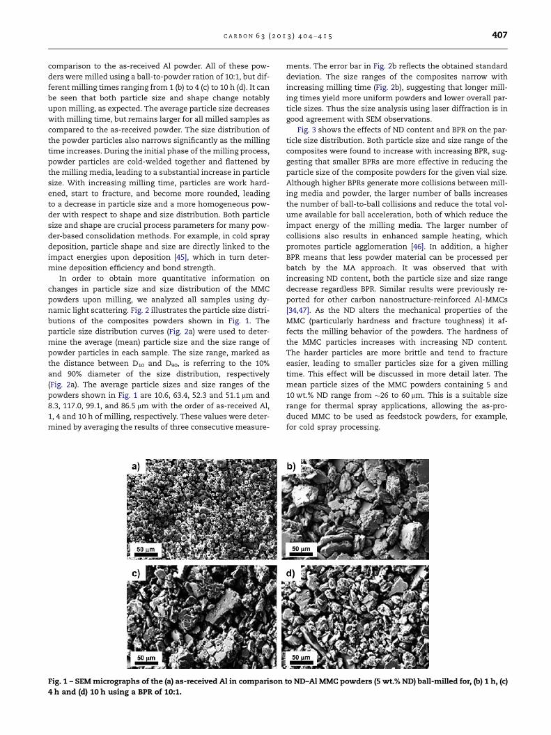
C A R B O N 6 3 ( 2 0 1 3 ) 4 0 4 – 4 1 5 407
comparison to the as-received Al powder. All of these pow-
ders were milled using a ball-to-powder ration of 10:1, but dif-
ferent milling times ranging from 1 (b) to 4 (c) to 10 h (d). It can
be seen that both particle size and shape change notably
upon milling, as expected. The average particle size decreases
with milling time, but remains larger for all milled samples as
compared to the as-received powder. The size distribution of
the powder particles also narrows significantly as the milling
time increases. During the initial phase of the milling process,
powder particles are cold-welded together and flattened by
the milling media, leading to a substantial increase in particle
size. With increasing milling time, particles are work hard-
ened, start to fracture, and become more rounded, leading
to a decrease in particle size and a more homogeneous pow-
der with respect to shape and size distribution. Both particle
size and shape are crucial process parameters for many pow-
der-based consolidation methods. For example, in cold spray
deposition, particle shape and size are directly linked to the
impact energies upon deposition [45], which in turn deter-
mine deposition efficiency and bond strength.
In order to obtain more quantitative information on
changes in particle size and size distribution of the MMC
powders upon milling, we analyzed all samples using dy-
namic light scattering. Fig. 2 illustrates the particle size distri-
butions of the composites powders shown in Fig. 1. The
particle size distribution curves (Fig. 2a) were used to deter-
mine the average (mean) particle size and the size range of
powder particles in each sample. The size range, marked as
the distance between D10 and D90, is referring to the 10%
and 90% diameter of the size distribution, respectively
(Fig. 2a). The average particle sizes and size ranges of the
powders shown in Fig. 1 are 10.6, 63.4, 52.3 and 51.1 lm and
8.3, 117.0, 99.1, and 86.5 lm with the order of as-received Al,
1, 4 and 10 h of milling, respectively. These values were deter-
mined by averaging the results of three consecutive measure-
Fig. 1 – SEM micrographs of the (a) as-received Al in comparison
4 h and (d) 10 h using a BPR of 10:1.
ments. The error bar in Fig. 2b reflects the obtained standard
deviation. The size ranges of the composites narrow with
increasing milling time (Fig. 2b), suggesting that longer mill-
ing times yield more uniform powders and lower overall par-
ticle sizes. Thus the size analysis using laser diffraction is in
good agreement with SEM observations.
Fig. 3 shows the effects of ND content and BPR on the par-
ticle size distribution. Both particle size and size range of the
composites were found to increase with increasing BPR, sug-
gesting that smaller BPRs are more effective in reducing the
particle size of the composite powders for the given vial size.
Although higher BPRs generate more collisions between mill-
ing media and powder, the larger number of balls increases
the number of ball-to-ball collisions and reduce the total vol-
ume available for ball acceleration, both of which reduce the
impact energy of the milling media. The larger number of
collisions also results in enhanced sample heating, which
promotes particle agglomeration [46]. In addition, a higher
BPR means that less powder material can be processed per
batch by the MA approach. It was observed that with
increasing ND content, both the particle size and size range
decrease regardless BPR. Similar results were previously re-
ported for other carbon nanostructure-reinforced Al-MMCs
[34,47]. As the ND alters the mechanical properties of the
MMC (particularly hardness and fracture toughness) it af-
fects the milling behavior of the powders. The hardness of
the MMC particles increases with increasing ND content.
The harder particles are more brittle and tend to fracture
easier, leading to smaller particles size for a given milling
time. This effect will be discussed in more detail later. The
mean particle sizes of the MMC powders containing 5 and
10 wt.% ND range from �26 to 60 lm. This is a suitable size
range for thermal spray applications, allowing the as-pro-
duced MMC to be used as feedstock powders, for example,
for cold spray processing.
to ND–Al MMC powders (5 wt.% ND) ball-milled for, (b) 1 h, (c)
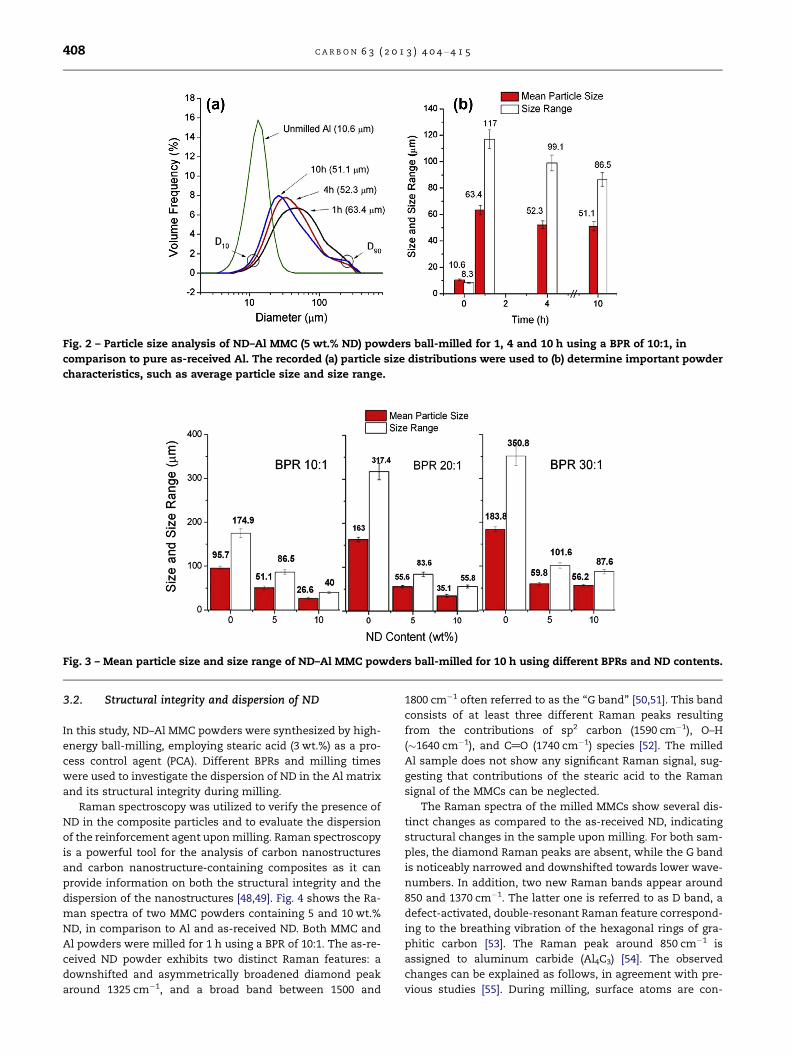
Fig. 2 – Particle size analysis of ND–Al MMC (5 wt.% ND) powders ball-milled for 1, 4 and 10 h using a BPR of 10:1, in
comparison to pure as-received Al. The recorded (a) particle size distributions were used to (b) determine important powder
characteristics, such as average particle size and size range.
Fig. 3 – Mean particle size and size range of ND–Al MMC powders ball-milled for 10 h using different BPRs and ND contents.
408 C A R B O N 6 3 ( 2 0 1 3 ) 4 0 4 – 4 1 5
3.2. Structural integrity and dispersion of ND
In this study, ND–Al MMC powders were synthesized by high-
energy ball-milling, employing stearic acid (3 wt.%) as a pro-
cess control agent (PCA). Different BPRs and milling times
were used to investigate the dispersion of ND in the Al matrix
and its structural integrity during milling.
Raman spectroscopy was utilized to verify the presence of
ND in the composite particles and to evaluate the dispersion
of the reinforcement agent upon milling. Raman spectroscopy
is a powerful tool for the analysis of carbon nanostructures
and carbon nanostructure-containing composites as it can
provide information on both the structural integrity and the
dispersion of the nanostructures [48,49]. Fig. 4 shows the Ra-
man spectra of two MMC powders containing 5 and 10 wt.%
ND, in comparison to Al and as-received ND. Both MMC and
Al powders were milled for 1 h using a BPR of 10:1. The as-re-
ceived ND powder exhibits two distinct Raman features: a
downshifted and asymmetrically broadened diamond peak
around 1325 cm�1, and a broad band between 1500 and
1800 cm�1 often referred to as the ‘‘G band’’ [50,51]. This band
consists of at least three different Raman peaks resulting
from the contributions of sp2 carbon (1590 cm�1), O–H
(�1640 cm�1), and C@O (1740 cm�1) species [52]. The milled
Al sample does not show any significant Raman signal, sug-
gesting that contributions of the stearic acid to the Raman
signal of the MMCs can be neglected.
The Raman spectra of the milled MMCs show several dis-
tinct changes as compared to the as-received ND, indicating
structural changes in the sample upon milling. For both sam-
ples, the diamond Raman peaks are absent, while the G band
is noticeably narrowed and downshifted towards lower wave-
numbers. In addition, two new Raman bands appear around
850 and 1370 cm�1. The latter one is referred to as D band, a
defect-activated, double-resonant Raman feature correspond-
ing to the breathing vibration of the hexagonal rings of gra-
phitic carbon [53]. The Raman peak around 850 cm�1 is
assigned to aluminum carbide (Al4C3) [54]. The observed
changes can be explained as follows, in agreement with pre-
vious studies [55]. During milling, surface atoms are con-
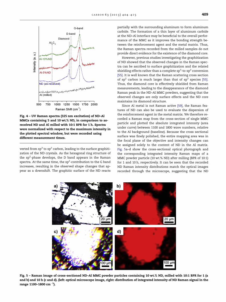
Fig. 4 – UV Raman spectra (325 nm excitation) of ND–Al
MMCs containing 5 and 10 wt.% ND, in comparison to as-
received ND and Al milled with 10:1 BPR for 1 h. Spectra
were normalized with respect to the maximum intensity in
the plotted spectral window, but were recorded using
different measurement times.
C A R B O N 6 3 ( 2 0 1 3 ) 4 0 4 – 4 1 5 409
verted from sp3 to sp2 carbon, leading to the surface graphiti-
zation of the ND crystals. As the hexagonal ring structure of
the sp2-phase develops, the D band appears in the Raman
spectra. At the same time, the sp2-contribution to the G band
increases, resulting in the observed shape changes that ap-
pear as a downshift. The graphitic surface of the ND reacts
Fig. 5 – Raman image of cross-sectioned ND–Al MMC powder pa
and b) and 10 h (c and d). (left: optical microscope image, right: d
range 1100–1800 cm�1).
partially with the surrounding aluminum to form aluminum
carbide. The formation of a thin layer of aluminum carbide
at the ND–Al interface may be beneficial to the overall perfor-
mance of the MMC as it improves the bonding strength be-
tween the reinforcement agent and the metal matrix. Thus,
the Raman spectra recorded from the milled samples do not
provide direct evidence for the existence of the diamond core.
However, previous studies investigating the graphitization
of ND showed that the observed changes in the Raman spec-
tra can be ascribed to surface graphitization and the related
shielding effects rather than a complete sp3-to-sp2 conversion
[55]. It is well known that the Raman scattering cross section
of sp2 carbon is much larger than that of sp3 species [55].
Thus, the diamond core is effectively shielded from Raman
measurements, leading to the disappearance of the diamond
Raman peak in the ND–Al MMC powders, suggesting that the
observed changes are only surface effects and the ND core
maintains its diamond structure.
Since Al metal is not Raman active [59], the Raman fea-
tures of ND can also be used to evaluate the dispersion of
the reinforcement agent in the metal matrix. We therefore re-
corded a Raman map from the cross-section of single MMC
particle and plotted the absolute integrated intensity (area
under curve) between 1100 and 1800 wave numbers, relative
to the Al background (baseline). Because the cross sectional
surface was finely polished, the entire mapping area was in
the focal plane of the objective and intensity changes can
be assigned solely to the content of ND in the Al matrix.
Fig. 5a–d show the cross-sectional optical photograph and
the corresponding integrated intensity Raman maps of a
MMC powder particle (10 wt.% ND) after milling (BPR of 10:1)
for 1 and 10 h, respectively. It can be seen that the recorded
ND Raman intensity distributions match the optical images
recorded through the microscope, suggesting that the ND
rticles containing 10 wt.% ND, milled with 10:1 BPR for 1 (a
istribution of integrated intensity of ND Raman signal in the
410 C A R B O N 6 3 ( 2 0 1 3 ) 4 0 4 – 4 1 5
agglomerates have been dispersed homogenously within the
Al particles, even after short milling times. However, it should
be noted that since the spatial resolution of the Raman spec-
trometer is limited to about 0.8 lm, statements about ND dis-
persion below this limit cannot be made. These results
demonstrate that high-energy ball milling is an effective
means for size reduction and dispersion of ND agglomerates
in an Al matrix, in analogy to CNT-Al composites [2,3].
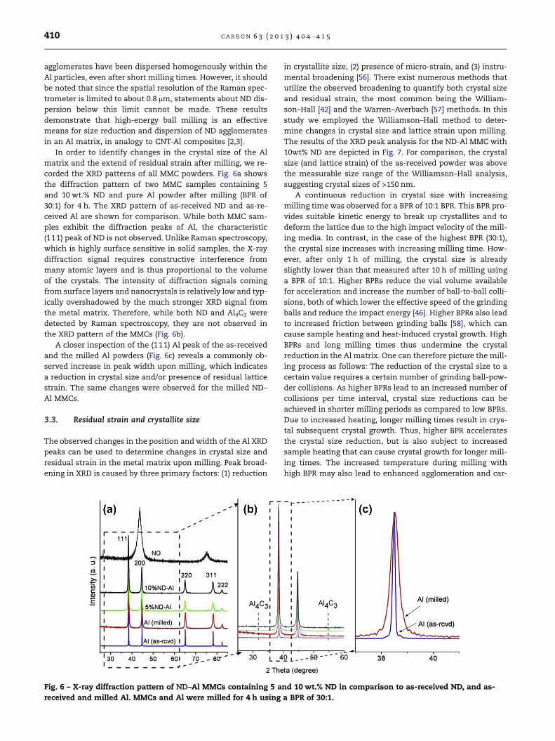
In order to identify changes in the crystal size of the Al
matrix and the extend of residual strain after milling, we re-
corded the XRD patterns of all MMC powders. Fig. 6a shows
the diffraction pattern of two MMC samples containing 5
and 10 wt.% ND and pure Al powder after milling (BPR of
30:1) for 4 h. The XRD pattern of as-received ND and as-re-
ceived Al are shown for comparison. While both MMC sam-
ples exhibit the diffraction peaks of Al, the characteristic
(111) peak of ND is not observed. Unlike Raman spectroscopy,
which is highly surface sensitive in solid samples, the X-ray
diffraction signal requires constructive interference from
many atomic layers and is thus proportional to the volume
of the crystals. The intensity of diffraction signals coming
from surface layers and nanocrystals is relatively low and typ-
ically overshadowed by the much stronger XRD signal from
the metal matrix. Therefore, while both ND and Al4C3 were
detected by Raman spectroscopy, they are not observed in
the XRD pattern of the MMCs (Fig. 6b).
A closer inspection of the (111) Al peak of the as-received
and the milled Al powders (Fig. 6c) reveals a commonly ob-
served increase in peak width upon milling, which indicates
a reduction in crystal size and/or presence of residual lattice
strain. The same changes were observed for the milled ND–
Al MMCs.
3.3. Residual strain and crystallite size
The observed changes in the position and width of the Al XRD
peaks can be used to determine changes in crystal size and
residual strain in the metal matrix upon milling. Peak broad-
ening in XRD is caused by three primary factors: (1) reduction
Fig. 6 – X-ray diffraction pattern of ND–Al MMCs containing 5 a
received and milled Al. MMCs and Al were milled for 4 h using
in crystallite size, (2) presence of micro-strain, and (3) instru-
mental broadening [56]. There exist numerous methods that
utilize the observed broadening to quantify both crystal size
and residual strain, the most common being the William-
son–Hall [42] and the Warren–Averbach [57] methods. In this
study we employed the Williamson–Hall method to deter-
mine changes in crystal size and lattice strain upon milling.
The results of the XRD peak analysis for the ND-Al MMC with
10wt% ND are depicted in Fig. 7. For comparison, the crystal
size (and lattice strain) of the as-received powder was above
the measurable size range of the Williamson–Hall analysis,
suggesting crystal sizes of >150 nm.
A continuous reduction in crystal size with increasing
milling time was observed for a BPR of 10:1 BPR. This BPR pro-
vides suitable kinetic energy to break up crystallites and to
deform the lattice due to the high impact velocity of the mill-
ing media. In contrast, in the case of the highest BPR (30:1),
the crystal size increases with increasing milling time. How-
ever, after only 1 h of milling, the crystal size is already
slightly lower than that measured after 10 h of milling using
a BPR of 10:1. Higher BPRs reduce the vial volume available
for acceleration and increase the number of ball-to-ball colli-
sions, both of which lower the effective speed of the grinding
balls and reduce the impact energy [46]. Higher BPRs also lead
to increased friction between grinding balls [58], which can
cause sample heating and heat-induced crystal growth. High
BPRs and long milling times thus undermine the crystal
reduction in the Al matrix. One can therefore picture the mill-
ing process as follows: The reduction of the crystal size to a
certain value requires a certain number of grinding ball-pow-
der collisions. As higher BPRs lead to an increased number of
collisions per time interval, crystal size reductions can be
achieved in shorter milling periods as compared to low BPRs.
Due to increased heating, longer milling times result in crys-
tal subsequent crystal growth. Thus, higher BPR accelerates
the crystal size reduction, but is also subject to increased
sample heating that can cause crystal growth for longer mill-
ing times. The increased temperature during milling with
high BPR may also lead to enhanced agglomeration and car-
nd 10 wt.% ND in comparison to as-received ND, and as-
a BPR of 30:1.
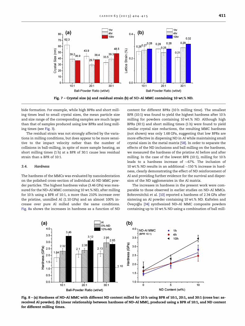
Fig. 7 – Crystal size (a) and residual strain (b) of ND–Al MMC containing 10 wt.% ND.
C A R B O N 6 3 ( 2 0 1 3 ) 4 0 4 – 4 1 5 411
bide formation. For example, while high BPRs and short mill-
ing times lead to small crystal sizes, the mean particle size
and size range of the corresponding samples are much larger
than that of samples produced using low BPRs and long mill-
ing times (see Fig. 3).
The residual strain was not strongly affected by the varia-
tions in milling conditions, but does appear to be more sensi-
tive to the impact velocity rather than the number of
collisions in ball-milling, in spite of more sample heating, as
short milling times (1 h) at a BPR of 30:1 cause less residual
strain than a BPR of 10:1.
3.4. Hardness
The hardness of the MMCs was evaluated by nanoindentation
on the polished cross-section of individual Al-ND MMC pow-
der particles. The highest hardness value (3.46 GPa) was mea-
sured for the ND–Al MMC containing 10 wt.% ND, after milling
for 10 h using a BPR of 10:1, a more than 210% increase over
the pristine, unmilled Al (1.10 GPa) and an almost 100% in-
crease over pure Al milled under the same conditions.
Fig. 8a shows the increases in hardness as a function of ND
Fig. 8 – (a) Hardness of ND–Al MMC with different ND content m
received Al powder). (b) Linear relationship between hardness o
for different milling times.
content for different BPRs (10 h milling time). The smallest
BPR (10:1) was found to yield the highest hardness after 10 h
milling for powders containing 10 wt.% ND. Although high
BPRs (30:1) and short milling times (1 h) were found to yield
similar crystal size reductions, the resulting MMC hardness
(not shown) was only 1.68 GPa, suggesting that low BPRs are
more effective in dispersing ND in Al while maintaining small
crystal sizes in the metal matrix [58]. In order to separate the
effects of the ND inclusions and ball milling on the hardness,
we measured the hardness of the pristine Al before and after
milling. In the case of the lowest BPR (10:1), milling for 10 h
leads to a hardness increase of �67%. The inclusion of
10 wt.% ND results in an additional �150 % increase in hard-
ness, clearly demonstrating the effect of ND reinforcement of
Al and providing further evidence for the survival and disper-
sion of the ND agglomerates in the Al matrix.
The increases in hardness in the present work were com-
parable to those observed in earlier studies on ND–Al MMCs.
Bobrovnitchii et al. [10] reported a hardness of 2.34 GPa after
sintering an Al powder containing 10 wt.% ND. Kaftelen and
Ovecoglu [34] synthesized ND–Al MMC composite powders
containing up to 10 wt.% ND using a combination of ball mill-
illed for 10 h using BPR of 10:1, 20:1, and 30:1 (cross bar: as-
f ND–Al MMC, produced using a BPR of 10:1, and ND content
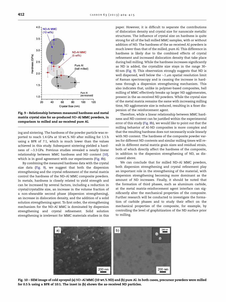
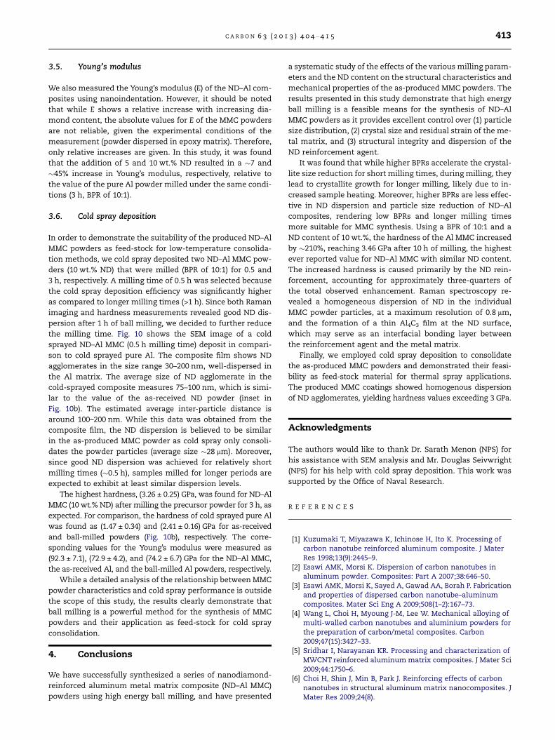
Fig. 9 – Relationship between measured hardness and metal
matrix crystal size for as-produced ND–Al MMC powders, in
comparison to milled and as-received pure Al.
412 C A R B O N 6 3 ( 2 0 1 3 ) 4 0 4 – 4 1 5
ing and sintering. The hardness of the powder particle was re-
ported to reach 1.4 GPa at 10 wt.% ND after milling for 1.5 h
using a BPR of 7:1, which is much lower than the values
achieved in this study. Subsequent sintering yielded a hard-
ness of �3.3 GPa. Previous studies revealed a nearly linear
relationship between MMC hardness and ND content [10],
which is in good agreement with our experiments (Fig. 8b).
By combining the measured hardness data with the crystal
size data (Fig. 9), we suggest that both the dispersion
strengthening and the crystal refinement of the metal matrix
control the hardness of the ND–Al MMC composite powders.
In metals, hardness is closely related to yield strength and
can be increased by several factors, including a reduction in
crystal/crystallite size, an increase in the volume fraction of
a non-shearable second phase (dispersion strengthening),
an increase in dislocation density, and the addition of a solid
solution strengthening agent. To first order, the strengthening
mechanism for the ND–Al MMC is dominated by dispersion
strengthening and crystal refinement. Solid solution
strengthening is irrelevant for MMC materials studies in this
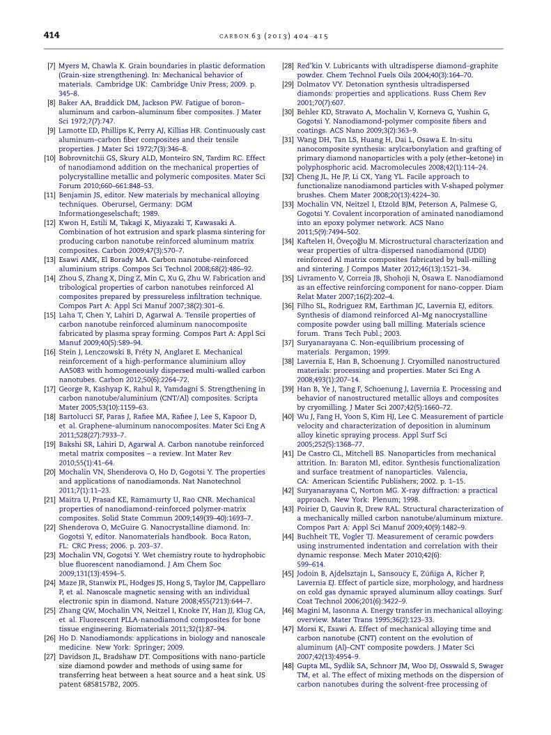
Fig. 10 – SEM image of cold sprayed (a) ND–Al MMC (10 wt.% ND)
for 0.5 h using a BPR of 10:1. The inset in (b) shows the as-rece
paper. However, it is difficult to separate the contributions
of dislocation density and crystal size for nanoscale metallic
structures. The influence of crystal size on hardness is quite
strong for all of the ball milled MMC samples, with or without
addition of ND. The hardness of the as-received Al powders is
much lower than that of the milled, pure Al. This difference in
hardness is likely due to the combined effects of crystal
refinement and increased dislocation density that take place
during ball milling. While the hardness increases significantly
as ND is added, the crystallite size stays in the range 30–
60 nm (Fig. 9). This observation strongly suggests that ND is
well dispersed, well below the �1 lm spatial resolution limit
of Raman spectroscopy and is causing the increase in hard-
ness through a dispersion strengthening mechanism. This
also indicates that, unlike in polymer-based composites, ball
milling of MMC effectively breaks up larger ND agglomerates,
present in the as-received ND powders. While the crystal size
of the metal matrix remains the same with increasing milling
time, ND agglomerate size is reduced, resulting in a finer dis-
persion of the reinforcement agent.
Therefore, while a linear relationship between MMC hard-
ness and ND content can be justified within the experimental
error of this study (Fig. 8b), we would like to point out that the
milling behavior of Al-ND composites is more complex and
that the resulting hardness does not necessarily scale linearly
with ND content. The hardness of the composite powder var-
ies for different ND contents and similar milling times will re-
sult in different metal matrix grain sizes and residual strain,
both of which directly affect the hardness of the composite,
in addition to the dispersion strengthening of ND, as dis-
cussed above.
We can conclude that for milled ND–Al MMC powders,
both dispersion strengthening and crystal refinement play
an important role in the strengthening of the material, with
dispersion strengthening becoming more dominant as the
amount of ND increases. Finally, it should be noted that
the formation of third phases, such as aluminum carbide,
at the metal matrix-reinforcement agent interface can sig-
nificantly alter the mechanical properties of the composite.
Further research will be conducted to investigate the forma-
tion of carbide phases and to study their effect on the
mechanical properties of the composite, for example, by
controlling the level of graphitization of the ND surface prior
to milling.
and (b) pure Al. In both cases, precursor powders were milled
ived ND particles.
C A R B O N 6 3 ( 2 0 1 3 ) 4 0 4 – 4 1 5 413
3.5. Young’s modulus
We also measured the Young’s modulus (E) of the ND–Al com-
posites using nanoindentation. However, it should be noted
that while E shows a relative increase with increasing dia-
mond content, the absolute values for E of the MMC powders
are not reliable, given the experimental conditions of the
measurement (powder dispersed in epoxy matrix). Therefore,
only relative increases are given. In this study, it was found
that the addition of 5 and 10 wt.% ND resulted in a �7 and
�45% increase in Young’s modulus, respectively, relative to
the value of the pure Al powder milled under the same condi-
tions (3 h, BPR of 10:1).
3.6. Cold spray deposition
In order to demonstrate the suitability of the produced ND–Al
MMC powders as feed-stock for low-temperature consolida-
tion methods, we cold spray deposited two ND–Al MMC pow-
ders (10 wt.% ND) that were milled (BPR of 10:1) for 0.5 and
3 h, respectively. A milling time of 0.5 h was selected because
the cold spray deposition efficiency was significantly higher
as compared to longer milling times (>1 h). Since both Raman
imaging and hardness measurements revealed good ND dis-
persion after 1 h of ball milling, we decided to further reduce
the milling time. Fig. 10 shows the SEM image of a cold
sprayed ND–Al MMC (0.5 h milling time) deposit in compari-
son to cold sprayed pure Al. The composite film shows ND
agglomerates in the size range 30–200 nm, well-dispersed in
the Al matrix. The average size of ND agglomerate in the
cold-sprayed composite measures 75–100 nm, which is simi-
lar to the value of the as-received ND powder (inset in
Fig. 10b). The estimated average inter-particle distance is
around 100–200 nm. While this data was obtained from the
composite film, the ND dispersion is believed to be similar
in the as-produced MMC powder as cold spray only consoli-
dates the powder particles (average size �28 lm). Moreover,
since good ND dispersion was achieved for relatively short
milling times (�0.5 h), samples milled for longer periods are
expected to exhibit at least similar dispersion levels.
The highest hardness, (3.26 ± 0.25) GPa, was found for ND–Al
MMC (10 wt.% ND) after milling the precursor powder for 3 h, as
expected. For comparison, the hardness of cold sprayed pure Al
was found as (1.47 ± 0.34) and (2.41 ± 0.16) GPa for as-received
and ball-milled powders (Fig. 10b), respectively. The corre-
sponding values for the Young’s modulus were measured as
(92.3 ± 7.1), (72.9 ± 4.2), and (74.2 ± 6.7) GPa for the ND–Al MMC,
the as-received Al, and the ball-milled Al powders, respectively.
While a detailed analysis of the relationship between MMC
powder characteristics and cold spray performance is outside
the scope of this study, the results clearly demonstrate that
ball milling is a powerful method for the synthesis of MMC
powders and their application as feed-stock for cold spray
consolidation.
4. Conclusions
We have successfully synthesized a series of nanodiamond-
reinforced aluminum metal matrix composite (ND–Al MMC)
powders using high energy ball milling, and have presented
a systematic study of the effects of the various milling param-
eters and the ND content on the structural characteristics and
mechanical properties of the as-produced MMC powders. The
results presented in this study demonstrate that high energy
ball milling is a feasible means for the synthesis of ND–Al
MMC powders as it provides excellent control over (1) particle
size distribution, (2) crystal size and residual strain of the me-
tal matrix, and (3) structural integrity and dispersion of the
ND reinforcement agent.
It was found that while higher BPRs accelerate the crystal-
lite size reduction for short milling times, during milling, they
lead to crystallite growth for longer milling, likely due to in-
creased sample heating. Moreover, higher BPRs are less effec-
tive in ND dispersion and particle size reduction of ND–Al
composites, rendering low BPRs and longer milling times
more suitable for MMC synthesis. Using a BPR of 10:1 and a
ND content of 10 wt.%, the hardness of the Al MMC increased
by �210%, reaching 3.46 GPa after 10 h of milling, the highest
ever reported value for ND–Al MMC with similar ND content.
The increased hardness is caused primarily by the ND rein-
forcement, accounting for approximately three-quarters of
the total observed enhancement. Raman spectroscopy re-
vealed a homogeneous dispersion of ND in the individual
MMC powder particles, at a maximum resolution of 0.8 lm,
and the formation of a thin Al4C3 film at the ND surface,
which may serve as an interfacial bonding layer between
the reinforcement agent and the metal matrix.
Finally, we employed cold spray deposition to consolidate
the as-produced MMC powders and demonstrated their feasi-
bility as feed-stock material for thermal spray applications.
The produced MMC coatings showed homogenous dispersion
of ND agglomerates, yielding hardness values exceeding 3 GPa.
Acknowledgments
The authors would like to thank Dr. Sarath Menon (NPS) for
his assistance with SEM analysis and Mr. Douglas Seivwright
(NPS) for his help with cold spray deposition. This work was
supported by the Office of Naval Research.
R E F E R E N C E S
[1] Kuzumaki T, Miyazawa K, Ichinose H, Ito K. Processing ofcarbon nanotube reinforced aluminum composite. J MaterRes 1998;13(9):2445–9.
[2] Esawi AMK, Morsi K. Dispersion of carbon nanotubes inaluminum powder. Composites: Part A 2007;38:646–50.
[3] Esawi AMK, Morsi K, Sayed A, Gawad AA, Borah P. Fabricationand properties of dispersed carbon nanotube–aluminumcomposites. Mater Sci Eng A 2009;508(1–2):167–73.
[4] Wang L, Choi H, Myoung J-M, Lee W. Mechanical alloying ofmulti-walled carbon nanotubes and aluminium powders forthe preparation of carbon/metal composites. Carbon2009;47(15):3427–33.
[5] Sridhar I, Narayanan KR. Processing and characterization ofMWCNT reinforced aluminum matrix composites. J Mater Sci2009;44:1750–6.
[6] Choi H, Shin J, Min B, Park J. Reinforcing effects of carbonnanotubes in structural aluminum matrix nanocomposites. JMater Res 2009;24(8).
414 C A R B O N 6 3 ( 2 0 1 3 ) 4 0 4 – 4 1 5
[7] Myers M, Chawla K. Grain boundaries in plastic deformation(Grain-size strengthening). In: Mechanical behavior ofmaterials. Cambridge UK: Cambridge Univ Press; 2009. p.345–8.
[8] Baker AA, Braddick DM, Jackson PW. Fatigue of boron–aluminum and carbon–aluminum fiber composites. J MaterSci 1972;7(7):747.
[9] Lamotte ED, Phillips K, Perry AJ, Killias HR. Continuously castaluminum–carbon fiber composites and their tensileproperties. J Mater Sci 1972;7(3):346–8.
[10] Bobrovnitchii GS, Skury ALD, Monteiro SN, Tardim RC. Effectof nanodiamond addition on the mechanical properties ofpolycrystalline metallic and polymeric composites. Mater SciForum 2010;660–661:848–53.
[11] Benjamin JS, editor. New materials by mechanical alloyingtechniques. Oberursel, Germany: DGMInformationgeselschaft; 1989.
[12] Kwon H, Estili M, Takagi K, Miyazaki T, Kawasaki A.Combination of hot extrusion and spark plasma sintering forproducing carbon nanotube reinforced aluminum matrixcomposites. Carbon 2009;47(3):570–7.
[13] Esawi AMK, El Borady MA. Carbon nanotube-reinforcedaluminium strips. Compos Sci Technol 2008;68(2):486–92.
[14] Zhou S, Zhang X, Ding Z, Min C, Xu G, Zhu W. Fabrication andtribological properties of carbon nanotubes reinforced Alcomposites prepared by pressureless infiltration technique.Compos Part A: Appl Sci Manuf 2007;38(2):301–6.
[15] Laha T, Chen Y, Lahiri D, Agarwal A. Tensile properties ofcarbon nanotube reinforced aluminum nanocompositefabricated by plasma spray forming. Compos Part A: Appl SciManuf 2009;40(5):589–94.
[16] Stein J, Lenczowski B, Frety N, Anglaret E. Mechanicalreinforcement of a high-performance aluminium alloyAA5083 with homogeneously dispersed multi-walled carbonnanotubes. Carbon 2012;50(6):2264–72.
[17] George R, Kashyap K, Rahul R, Yamdagni S. Strengthening incarbon nanotube/aluminium (CNT/Al) composites. ScriptaMater 2005;53(10):1159–63.
[18] Bartolucci SF, Paras J, Rafiee MA, Rafiee J, Lee S, Kapoor D,et al. Graphene–aluminum nanocomposites. Mater Sci Eng A2011;528(27):7933–7.
[19] Bakshi SR, Lahiri D, Agarwal A. Carbon nanotube reinforcedmetal matrix composites – a review. Int Mater Rev2010;55(1):41–64.
[20] Mochalin VN, Shenderova O, Ho D, Gogotsi Y. The propertiesand applications of nanodiamonds. Nat Nanotechnol2011;7(1):11–23.
[21] Maitra U, Prasad KE, Ramamurty U, Rao CNR. Mechanicalproperties of nanodiamond-reinforced polymer-matrixcomposites. Solid State Commun 2009;149(39–40):1693–7.
[22] Shenderova O, McGuire G. Nanocrystalline diamond. In:Gogotsi Y, editor. Nanomaterials handbook. Boca Raton,FL: CRC Press; 2006. p. 203–37.
[23] Mochalin VN, Gogotsi Y. Wet chemistry route to hydrophobicblue fluorescent nanodiamond. J Am Chem Soc2009;131(13):4594–5.
[24] Maze JR, Stanwix PL, Hodges JS, Hong S, Taylor JM, CappellaroP, et al. Nanoscale magnetic sensing with an individualelectronic spin in diamond. Nature 2008;455(7213):644–7.
[25] Zhang QW, Mochalin VN, Neitzel I, Knoke IY, Han JJ, Klug CA,et al. Fluorescent PLLA-nanodiamond composites for bonetissue engineering. Biomaterials 2011;32(1):87–94.
[26] Ho D. Nanodiamonds: applications in biology and nanoscalemedicine. New York: Springer; 2009.
[27] Davidson JL, Bradshaw DT. Compositions with nano-particlesize diamond powder and methods of using same fortransferring heat between a heat source and a heat sink. USpatent 6858157B2, 2005.
[28] Red’kin V. Lubricants with ultradisperse diamond–graphitepowder. Chem Technol Fuels Oils 2004;40(3):164–70.
[29] Dolmatov VY. Detonation synthesis ultradisperseddiamonds: properties and applications. Russ Chem Rev2001;70(7):607.
[30] Behler KD, Stravato A, Mochalin V, Korneva G, Yushin G,Gogotsi Y. Nanodiamond-polymer composite fibers andcoatings. ACS Nano 2009;3(2):363–9.
[31] Wang DH, Tan LS, Huang H, Dai L, Osawa E. In-situnanocomposite synthesis: arylcarbonylation and grafting ofprimary diamond nanoparticles with a poly (ether–ketone) inpolyphosphoric acid. Macromolecules 2008;42(1):114–24.
[32] Cheng JL, He JP, Li CX, Yang YL. Facile approach tofunctionalize nanodiamond particles with V-shaped polymerbrushes. Chem Mater 2008;20(13):4224–30.
[33] Mochalin VN, Neitzel I, Etzold BJM, Peterson A, Palmese G,Gogotsi Y. Covalent incorporation of aminated nanodiamondinto an epoxy polymer network. ACS Nano2011;5(9):7494–502.
[34] Kaftelen H, Ovecoglu M. Microstructural characterization andwear properties of ultra-dispersed nanodiamond (UDD)reinforced Al matrix composites fabricated by ball-millingand sintering. J Compos Mater 2012;46(13):1521–34.
[35] Livramento V, Correia JB, Shohoji N, �Osawa E. Nanodiamondas an effective reinforcing component for nano-copper. DiamRelat Mater 2007;16(2):202–4.
[36] Filho SL, Rodriguez RM, Earthman JC, Lavernia EJ, editors.Synthesis of diamond reinforced Al–Mg nanocrystallinecomposite powder using ball milling. Materials scienceforum. Trans Tech Publ.; 2003.
[37] Suryanarayana C. Non-equilibrium processing ofmaterials. Pergamon; 1999.
[38] Lavernia E, Han B, Schoenung J. Cryomilled nanostructuredmaterials: processing and properties. Mater Sci Eng A2008;493(1):207–14.
[39] Han B, Ye J, Tang F, Schoenung J, Lavernia E. Processing andbehavior of nanostructured metallic alloys and compositesby cryomilling. J Mater Sci 2007;42(5):1660–72.
[40] Wu J, Fang H, Yoon S, Kim HJ, Lee C. Measurement of particlevelocity and characterization of deposition in aluminumalloy kinetic spraying process. Appl Surf Sci2005;252(5):1368–77.
[41] De Castro CL, Mitchell BS. Nanoparticles from mechanicalattrition. In: Baraton MI, editor. Synthesis functionalizationand surface treatment of nanoparticles. Valencia,CA: American Scientific Publishers; 2002. p. 1–15.
[42] Suryanarayana C, Norton MG. X-ray diffraction: a practicalapproach. New York: Plenum; 1998.
[43] Poirier D, Gauvin R, Drew RAL. Structural characterization ofa mechanically milled carbon nanotube/aluminum mixture.Compos Part A: Appl Sci Manuf 2009;40(9):1482–9.
[44] Buchheit TE, Vogler TJ. Measurement of ceramic powdersusing instrumented indentation and correlation with theirdynamic response. Mech Mater 2010;42(6):599–614.
[45] Jodoin B, Ajdelsztajn L, Sansoucy E, Zuniga A, Richer P,Lavernia EJ. Effect of particle size, morphology, and hardnesson cold gas dynamic sprayed aluminum alloy coatings. SurfCoat Technol 2006;201(6):3422–9.
[46] Magini M, Iasonna A. Energy transfer in mechanical alloying:overview. Mater Trans 1995;36(2):123–33.
[47] Morsi K, Esawi A. Effect of mechanical alloying time andcarbon nanotube (CNT) content on the evolution ofaluminum (Al)–CNT composite powders. J Mater Sci2007;42(13):4954–9.
[48] Gupta ML, Sydlik SA, Schnorr JM, Woo DJ, Osswald S, SwagerTM, et al. The effect of mixing methods on the dispersion ofcarbon nanotubes during the solvent-free processing of
C A R B O N 6 3 ( 2 0 1 3 ) 4 0 4 – 4 1 5 415
multiwalled carbon nanotube/epoxy composites. J Polym SciPart B: Polym Phys 2013;51(6):410–20.
[49] Mu MF, Osswald S, Gogotsi Y, Winey KI. An in situ Ramanspectroscopy study of stress transfer between carbonnanotubes and polymer. Nanotechnology 2009;20(33):335703.
[50] Ferrari AC, Robertson J. Raman spectroscopy of amorphous,nanostructured, diamond-like carbon, and nanodiamond.Philos Trans R Soc Lond Ser A: Math Phys Eng Sci2004;362(1824):2477–512.
[51] Osswald S, Mochalin VN, Havel M, Yushin G, Gogotsi Y.Phonon confinement effects in the Raman spectrum ofnanodiamond. Phys Rev B 2009;80(7):075419.
[52] Mochalin V, Osswald S, Gogotsi Y. Contribution of functionalgroups to the Raman spectrum of nanodiamond powders.Chem Mater 2009;21(2):273–9.
[53] Reich S, Thomsen C. Raman spectroscopy of graphite. PhilosTrans R Soc Lond Ser A: Math Phys Eng Sci2004;362(1824):2271–88.
[54] Zameshin A, Popov M, Medvedev V, Perfilov S, Lomakin R,Buga S, et al. Electrical conductivity of nanostructured andC60-modified aluminum. Appl Phys A 2012;107(4):863–9.
[55] Cebik J, McDonough J, Peerally F, Medrano R, Neitzel I,Gogotsi Y, et al. Raman Spectroscopy of the Transformationof Detonation Nanodiamond to Carbon Onions during LowTemperature Annealing. Nanotechnology2013;24(20):205703.
[56] He HH. Two-dimensional X-ray diffraction. Hoboken,NJ: Wiley Publishing; 2011.
[57] Warren B, Averbach B. The Effect of cold-work distortion onX-Ray patterns. J Appl Phys 1950;21(6):595–9.
[58] Suryanarayana C. Mechanical alloying and milling. ProgMater Sci 2001;46:1–184.
[59] Nafie LA. Theory of Raman Scattering. In: Lewis IR, EdwardsHGM, editors. Handbook of Raman spectroscopy. CRCPress: New York; 2001. p. 1–10.