synplify for actel user...
TRANSCRIPT

Synplify®
for Actel
User Guide
September 2004
Synplicity, Inc.600 West California Avenue
Sunnyvale, CA 94086(U.S.) +1 408 215-6000 direct
(U.S.) +1 408 222-0263 faxwww.synplicity.com
LO
Preface
ii Synplify User Guide, September 2004
Preface
Disclaimer of WarrantySynplicity, Inc. makes no representations or warranties, either expressed or implied, by or with respect to anything in this manual, and shall not be liable for any implied warranties of merchantability or fitness for a particular purpose of for any indirect, special or consequential damages.
Copyright NoticeCopyright © 1994-2004 Synplicity, Inc. All Rights Reserved.
Synplicity software products contain certain confidential information of Synplicity, Inc. Use of this copyright notice is precautionary and does not imply publication or disclosure. No part of this publication may be repro-duced, transmitted, transcribed, stored in a retrieval system, or translated into any language in any form by any means without the prior written permission of Synplicity, Inc. While every precaution has been taken in the preparation of this book, Synplicity, Inc. assumes no responsibility for errors or omissions. This publication and the features described herein are subject to change without notice.
TrademarksSynplicity, the Synplicity “S” logo, Behavior Extracting Synthesis Technology, Embedded Synthesis, HDL Analyst, SCOPE, Simply Better Results, Simply Better Synthesis, Synplify, and Synthesis Constraint Optimization Environ-ment are registered trademarks of Synplicity, Inc.
Amplify, B.E.S.T., Certify, DST, Direct Synthesis Technology, Partition-Driven Synthesis, and Physical Optimizer are trademarks of Synplicity, Inc.

Preface
Synplify User Guide, September 2004 iii
Verilog is a registered trademark of Cadence Design Systems, Inc. IBM and PC are registered trademarks of International Business Machines Corpora-tion. Microsoft is a registered trademark of Microsoft Corporation. Sun, SPARC, Solaris, and SunOS are trademarks of Sun Microsystems, Inc. UNIX is a registered trademark of UNIX Systems Laboratories, Inc.
All other product names mentioned herein are the trademarks or registered trademarks of their respective owners.
Synplicity products are protected under U.S. Patent No. 6,182,268.
Restricted Rights LegendGovernment Users: Use, reproduction, release, modification, or disclosure of this commercial computer software, or of any related documentation of any kind, is restricted in accordance with FAR 12.212 and DFARS 227.7202, and further restricted by the Synplicity Software License Agreement. Synplicity, Inc., 600 West California Avenue, Sunnyvale, CA 94086, U.S.A
Printed in the U.S.ASeptember 2004

LO
Preface
iv Synplify User Guide, September 2004
Synplicity Software License Agreement
Important! READ CAREFULLY BEFORE PROCEEDING
BY INDICATING YOUR ACCEPTANCE OF THE TERMS OF THIS AGREEMENT, YOU ARE REPRESENT-ING THAT YOU HAVE THE RIGHT AND AUTHORITY TO LEGALLY BIND YOURSELF OR YOUR COM-PANY, AS APPLICABLE, AND CONSENTING TO BE LEGALLY BOUND BY ALL OF THE TERMS OF THIS AGREEMENT. IF YOU DO NOT AGREE TO ALL THESE TERMS DO NOT INSTALL OR USE THE SOFT-WARE, AND RETURN THE SOFTWARE TO THE LOCATION OF PURCHASE FOR A REFUND. This is a legal agreement governing use of the software program ("SOFTWARE") provided to you ("Licensee") by Syn-plicity. The term "SOFTWARE" also includes related documentation (whether in print or electronic form) and any updates or upgrades of the SOFTWARE provided by Synplicity, but does not include certain software licensed by third party licensors and made available to you by Synplicity under the terms of such third party licensor's license (including software licensed under the General Public License (GPL)). If Licensee is a par-ticipant in the University Program or has been granted an Evaluation License, then some of the following terms and conditions may not apply (refer to the sections entitled, respectively, Evaluation License and Uni-versity Program, below).
Evaluation License. If Licensee has obtained the SOFTWARE pursuant to an evaluation license, then, in addi-tion to all other terms and conditions, the following restrictions apply: (a) The license to the SOFTWARE ter-minates after 20 days (unless otherwise agreed to in writing by Synplicity); and (b) Licensee may use the SOFTWARE only for the sole purpose of internal testing and evaluation to determine whether Licensee wishes to license the SOFTWARE on a commercial basis. Licensee shall not use the SOFTWARE to design any inte-grated circuits for production or pre-production purposes or any other commercial use including, but not lim-ited to, for the benefit of Licensee's customers. If Licensee breaches any of the foregoing restrictions, then Licensee shall pay to Synplicity a license fee equal to Synplicity's standard license fee for the commercial ver-sion of the SOFTWARE.
License. Synplicity grants to Licensee a non-exclusive right to install the SOFTWARE and to use or authorize use of the SOFTWARE by up to the number of nodes for which Licensee has a license and for which Licensee has the security key(s) or authorization code(s) provided by Synplicity or its agents. If Licensee has obtained the SOFTWARE under a node-locked license, then a "node" refers to a specific machine, and the SOFTWARE may be installed only on the number of "nodes" or machines authorized, must be used only on the machine(s) on which it is installed, and may be accessed only by users who are physically present at that node or machine. A node-locked license may only be used by one user at a time running one instance of the software at a time. If Licensee has obtained the SOFTWARE under a "floating" license, then a "node" refers to a concurrent user or session, and the SOFTWARE may be used concurrently by up to the number of users or sessions indicated. All SOFTWARE must be used within the country for which the systems were licensed and at Licensee's Site (con-tained within a one kilometer radius); however, if Licensee has a floating license then remote use is permitted by employees who work at the site but are temporarily telecommuting to that same site from less than 50 miles away (for example, an employee who works at a home office on occasion), but the maximum number of con-current sessions or nodes still applies. In addition, Synplicity grants to Licensee a non-exclusive license to copy and distribute internally the documentation portion of the SOFTWARE in support of its license to use the program portion of the SOFTWARE. For purposes of this Agreement the "Licensee's Site" means the location of the server on which the SOFTWARE resides, or when a server is not required, the location of the client com-

Preface
Synplify User Guide, September 2004 v
puter for which the license was issued.
Copy Restrictions. This SOFTWARE is protected by United States copyright laws and international treaty pro-visions and Licensee may copy the SOFTWARE only as follows: (i) to directly support authorized use under the license, and (ii) in order to make a copy of the SOFTWARE for backup purposes. Copies must include all copyright and trademark notices.
Use Restrictions. This SOFTWARE is licensed to Licensee for internal use only. Licensee shall not (and shall not allow any third party to): (i) decompile, disassemble, reverse engineer or attempt to reconstruct, identify or discover any source code, underlying ideas, underlying user interface techniques or algorithms of the SOFT-WARE by any means whatever, or disclose any of the foregoing; (ii) provide, lease, lend, or use the SOFT-WARE for timesharing or service bureau purposes, on an application service provider basis, or otherwise circumvent the internal use restrictions; (iii) modify, incorporate into or with other software, or create a deriva-tive work of any part of the SOFTWARE; (iv) disclose the results of any benchmarking of the SOFTWARE, or use such results for its own competing software development activities, without the prior written permission of Synplicity; or (v) attempt to circumvent any user limits, maximum gate count limits or other license, timing or use restrictions that are built into the SOFTWARE.
Transfer Restrictions/No Assignment. The SOFTWARE may only be used under this license at the desig-nated locations and designated equipment as set forth in the license grant above, and may not be moved to other locations or equipment or otherwise transferred without the prior written consent of Synplicity. Any per-mitted transfer of the SOFTWARE will require that Licensee executes a "Software Authorization Transfer Agreement" provided by Synplicity. Further, Licensee shall not sublicense, or assign this Agreement or any of the rights or licenses granted under this Agreement, without the prior written consent of Synplicity.
Security. Licensee agrees to take all appropriate measures to safeguard the SOFTWARE and prevent unautho-rized access or use thereof, including without limitation: (i) implementation of firewalls and other security applications, (ii) use of FLEXlm options file that restricts access to the SOFTWARE to identified users; (iii) maintaining and storing license information in paper format only; (iv) changing TCP port numbers every three (3) months; and (v) communicating to all authorized users that use of the SOFTWARE is subject to the restric-tions set forth in this Agreement.
Ownership of the SOFTWARE. Synplicity retains all right, title, and interest in the SOFTWARE (including all copies), and all worldwide intellectual property rights therein. Synplicity reserves all rights not expressly granted to Licensee. This License is not a sale of the original SOFTWARE or of any copy.
Ownership of Design Techniques. "Design" means the representation of an electronic circuit or device(s), derived or created by Licensee through the use of the SOFTWARE in its various formats, including, but not limited to, equations, truth tables, schematic diagrams, textual descriptions, hardware description languages, and netlists. "Design Techniques" means the data, circuit and logic elements, libraries, algorithms, search strat-egies, rule bases, and technical information incorporated in the SOFTWARE and employed in the process of creating Designs. Synplicity retains all right, title and interest in and to Design Techniques incorporated into the SOFTWARE, including all intellectual property rights embodied therein. Licensee acknowledges that Syn-plicity has an unrestricted, royalty-free right to incorporate any Design Techniques disclosed by Licensee into its software, documentation and other products, and to sublicense third parties to use those incorporated design techniques.

LO
Preface
vi Synplify User Guide, September 2004
Termination. Synplicity may terminate this Agreement immediately if Licensee breaches any provision, including without limitation, failure by Licensee to implement the Security measures set forth above. Upon notice of termination by Synplicity, all rights granted to Licensee under this Agreement will immediately ter-minate, and Licensee shall cease using the SOFTWARE and return or destroy all copies (and partial copies) of the SOFTWARE and documentation.
Limited Warranty and Disclaimer. Synplicity warrants that the program portion of the SOFTWARE will per-form substantially in accordance with the accompanying documentation for a period of 90 days from the date of receipt. Synplicity's entire liability and Licensee's exclusive remedy for a breach of the preceding limited warranty shall be, at Synplicity's option, either (a) return of the license fee, or (b) providing a fix, patch, work-around, or replacement of the SOFTWARE that does not meet such limited warranty. In either case, Lic-ensee must return the SOFTWARE to Synplicity with a copy of the purchase receipt or similar document. Replacements are warranted for the remainder of the original warranty period or 30 days, whichever is longer. Some states/jurisdictions do not allow limitations, so the above limitation may not apply. EXCEPT AS EXPRESSLY SET FORTH ABOVE, NO OTHER WARRANTIES OR CONDITIONS, EITHER EXPRESS, IMPLIED, STATUTORY OR OTHERWISE, ARE MADE BY SYNPLICITY OR ITS LICENSORS WITH RESPECT TO THE SOFTWARE AND THE ACCOMPANYING DOCUMENTATION, AND SYNPLICITY EXPRESSLY DISCLAIMS ALL WARRANTIES AND CONDITIONS NOT EXPRESSLY STATED HEREIN, INCLUDING BUT NOT LIMITED TO THE IMPLIED WARRANTIES OR CONDITIONS OF MERCHANT-ABILITY, NONINFRINGEMENT, AND FITNESS FOR A PARTICULAR PURPOSE. SYNPLICITY AND ITS LICENSORS DO NOT WARRANT THAT THE FUNCTIONS CONTAINED IN THE SOFTWARE WILL MEET LICENSEE'S REQUIREMENTS, BE UNINTERRUPTED OR ERROR FREE, OR THAT ALL DEFECTS IN THE PROGRAM WILL BE CORRECTED. Licensee assumes the entire risk as to the results and performance of the SOFTWARE. Some states/jurisdictions do not allow the exclusion of implied warranties, so the above exclu-sion may not apply.
Limitation of Liability. IN NO EVENT SHALL SYNPLICITY OR ITS LICENSORS OR THEIR AGENTS BE LIABLE FOR ANY INDIRECT, SPECIAL, CONSEQUENTIAL OR INCIDENTAL DAMAGES WHATSOEVER (INCLUDING, WITHOUT LIMITATION, DAMAGES FOR LOSS OF BUSINESS PROFITS, BUSINESS INTER-RUPTIONS, LOSS OF BUSINESS INFORMATION, OR OTHER PECUNIARY LOSS) ARISING OUT OF THE USE OF OR INABILITY TO USE THE SOFTWARE, EVEN IF SYNPLICITY AND/OR ITS LICENSORS HAVE BEEN ADVISED OF THE POSSIBILITY OF SUCH DAMAGES. FURTHER, IN NO EVENT SHALL SYNPLIC-ITY'S LICENSORS BE LIABLE FOR ANY DIRECT DAMAGES ARISING OUT OF LICENSEE'S USE OF THE SOFTWARE. In no event will Synplicity or its licensors be liable to Licensee for damages in an amount greater than the fees paid for the use of the SOFTWARE. Some states/jurisdictions do not allow the limitation or exclu-sion of incidental or consequential damages, so the above limitations or exclusions may not apply.
Intellectual Property Right Infringement. If a claim alleging infringement of an intellectual property right arises concerning the SOFTWARE (including but not limited to patent, trade secret, copyright or trademark rights), Synplicity in its sole discretion may elect to defend or settle such claim, and/or terminate this Agree-ment and all rights to use the SOFTWARE, and require the return or destruction of the SOFTWARE, with a refund of the fees paid for use of the SOFTWARE less a reasonable allowance for use and shipping.
Export. Licensee warrants that it is not prohibited from receiving the SOFTWARE under U.S. export laws; that it is not a national of a country subject to U.S. trade sanctions; that it will not use the SOFTWARE in a location that is the subject of U.S. trade sanctions that would cover the SOFTWARE; and that to its knowledge it is not on the U.S. Department of Commerce's table of deny orders or otherwise prohibited from obtaining goods of this sort from the United States.

Preface
Synplify User Guide, September 2004 vii
Miscellaneous. This Agreement is the entire agreement between Licensee and Synplicity with respect to the license to the SOFTWARE, and supersedes any previous oral or written communications or documents (includ-ing, if you are obtaining an update, any agreement that may have been included with the initial version of the SOFTWARE). This Agreement is governed by the laws of the State of California, USA excluding its conflicts of laws principals. This Agreement will not be governed by the U. N. Convention on Contracts for the Interna-tional Sale of Goods and will not be governed by any statute based on or derived from the Uniform Computer Information Transactions Act (UCITA). If any provision, or portion thereof, of this Agreement is found to be invalid or unenforceable, it will be enforced to the extent permissible and the remainder of this Agreement will remain in full force and effect. Failure to prosecute a party's rights with respect to a default hereunder will not constitute a waiver of the right to enforce rights with respect to the same or any other breach.
Government Users. The Software contains commercial computer software and commercial computer soft-ware documentation. In accordance with FAR 12.212 and DFARS 227.7202, use, duplication or disclosure is subject to restrictions under paragraph (c)(1)(ii) of the Rights in Technical Data and Computer Software clause at 252.227-7013, and further restricted by this Agreement. Synplicity, Inc., 600 W. California Avenue, Sunny-vale, CA 94086, U. S. A.
University Program. The following section applies only if Licensee is a participant in Synplicity's University Program; it does not replace the remainder of the Agreement and supersedes only those terms that directly con-flict.
University Program: License. Subject to the terms and conditions of this Agreement, Synplicity hereby grants to Licensee (a University) for the License Term (defined below), a non-exclusive license, only for purposes of course work or teaching in connection with a university-sponsored class, or for academic research either spon-sored by or conducted under the auspices of Licensee, to (a) install and use the SOFTWARE, and (b) reproduce and distribute copies of the documentation included in the SOFTWARE subject only to payment for those cop-ies (which may be based on the number of users, the number and type of copies, or both). If the SOFTWARE is licensed pursuant to a node-locked license, then the Licensee may install and use the SOFTWARE on the authorized workstations. If the SOFTWARE is licensed pursuant to a floating license, then the Licensee may install the SOFTWARE on the authorized server and use the SOFTWARE on up to the number of nodes for which Licensee has paid license fees and Synplicity has granted authorization.
University Program: License Term and Termination. For purposes of the University Program, "License Term" means one year unless otherwise agreed to in writing. This Agreement will terminate at the end of the License Term, unless earlier terminated in accordance with this Agreement.
University Program: License Restrictions. As Licensee, University may not (i) allow access to the SOFTWARE by any user not registered for a course or participating in an academic research project for which use of the SOFTWARE has been authorized; (ii) use the SOFTWARE to design any commercial products; or (iii) disclose the results of any benchmarking of the SOFTWARE, or use such results for its own competing software devel-opment activities, without the prior written permission of Synplicity.
University Program: Technical Liaison. Licensee shall appoint a Technical Liaison who will serve as the single point of contact between Synplicity and Licensee with respect to the subject matter of this Agreement. The Technical Liaison will coordinate installation and maintenance of the SOFTWARE, communicate with Synplic-ity regarding license procedures, administer Licensee's obligations under this Agreement and respond to inquiries by Synplicity related to the subject matter of this Agreement.

LO
Preface
viii Synplify User Guide, September 2004
University Program: Technical Support in North America. Unless otherwise agreed in writing, Synplicity will accept calls only from the appointed Technical Liaison. No technical support will be provided other than calls from the Technical Liaison relating to installation of the SOFTWARE. SOFTWARE upgrades may be obtained from the Synplicity Web Site.
University Program: International Technical Support. Technical support is provided through Synplicity's authorized distributors in accordance with their applicable policies.
revised 7/03
Synplify User Guide, September 2004 ix
Contents
Chapter 1: IntroductionThe Synplify Synthesis Tool . . . . . . . . . . . . . . . . . . . . . . . . . . . . . . . . . . . . . . . . . . 1-2
About the Software . . . . . . . . . . . . . . . . . . . . . . . . . . . . . . . . . . . . . . . . . . . . . . 1-2Synplicity Product Family . . . . . . . . . . . . . . . . . . . . . . . . . . . . . . . . . . . . . . . . . 1-3
The Generic FPGA Design Flow . . . . . . . . . . . . . . . . . . . . . . . . . . . . . . . . . . . . . . 1-4HDL Design Entry . . . . . . . . . . . . . . . . . . . . . . . . . . . . . . . . . . . . . . . . . . . . . . 1-4Logic Optimization (Compilation) . . . . . . . . . . . . . . . . . . . . . . . . . . . . . . . . . . . 1-5Technology Mapping . . . . . . . . . . . . . . . . . . . . . . . . . . . . . . . . . . . . . . . . . . . . 1-5Placement . . . . . . . . . . . . . . . . . . . . . . . . . . . . . . . . . . . . . . . . . . . . . . . . . . . . 1-5Routing . . . . . . . . . . . . . . . . . . . . . . . . . . . . . . . . . . . . . . . . . . . . . . . . . . . . . . . 1-6FPGA Configuration . . . . . . . . . . . . . . . . . . . . . . . . . . . . . . . . . . . . . . . . . . . . . 1-6
Audience . . . . . . . . . . . . . . . . . . . . . . . . . . . . . . . . . . . . . . . . . . . . . . . . . . . . . . . . . 1-6
Scope of the Document . . . . . . . . . . . . . . . . . . . . . . . . . . . . . . . . . . . . . . . . . . . . . 1-7
Starting the Software . . . . . . . . . . . . . . . . . . . . . . . . . . . . . . . . . . . . . . . . . . . . . . . 1-7Getting Started . . . . . . . . . . . . . . . . . . . . . . . . . . . . . . . . . . . . . . . . . . . . . . . . . 1-7Using the License Wizard . . . . . . . . . . . . . . . . . . . . . . . . . . . . . . . . . . . . . . . . 1-8Getting Help . . . . . . . . . . . . . . . . . . . . . . . . . . . . . . . . . . . . . . . . . . . . . . . . . . 1-10
User Interface Overview . . . . . . . . . . . . . . . . . . . . . . . . . . . . . . . . . . . . . . . . . . . . 1-11
The Design Flow . . . . . . . . . . . . . . . . . . . . . . . . . . . . . . . . . . . . . . . . . . . . . . . . . . 1-12
Chapter 2: File SetupSetting Up HDL Source Files . . . . . . . . . . . . . . . . . . . . . . . . . . . . . . . . . . . . . . . . . 2-2
Creating Source Files . . . . . . . . . . . . . . . . . . . . . . . . . . . . . . . . . . . . . . . . . . . . 2-2Checking Source Files . . . . . . . . . . . . . . . . . . . . . . . . . . . . . . . . . . . . . . . . . . . 2-4Editing Source Files with the Built-in Text Editor . . . . . . . . . . . . . . . . . . . . . . . 2-5Using an External Text Editor . . . . . . . . . . . . . . . . . . . . . . . . . . . . . . . . . . . . . 2-8Setting Editing Window Preferences . . . . . . . . . . . . . . . . . . . . . . . . . . . . . . . . 2-9
Setting Up Project Files . . . . . . . . . . . . . . . . . . . . . . . . . . . . . . . . . . . . . . . . . . . . 2-11Creating a Project File Without the Project Wizard . . . . . . . . . . . . . . . . . . . . 2-11
LO
Preface
x Synplify User Guide, September 2004
Creating a Project File with the Project Wizard . . . . . . . . . . . . . . . . . . . . . . . 2-14Opening an Existing Project File . . . . . . . . . . . . . . . . . . . . . . . . . . . . . . . . . . 2-15Making Changes to a Project . . . . . . . . . . . . . . . . . . . . . . . . . . . . . . . . . . . . . 2-16Setting Project View Display Preferences . . . . . . . . . . . . . . . . . . . . . . . . . . . 2-18
Chapter 3: Constraints, Attributes, and OptionsSetting Implementation Options . . . . . . . . . . . . . . . . . . . . . . . . . . . . . . . . . . . . . . . 3-2
Setting Device Options . . . . . . . . . . . . . . . . . . . . . . . . . . . . . . . . . . . . . . . . . . . 3-2Setting Constraint and Optimization Options . . . . . . . . . . . . . . . . . . . . . . . . . . 3-5Specifying Result Options . . . . . . . . . . . . . . . . . . . . . . . . . . . . . . . . . . . . . . . . 3-6Specifying Timing Report Output . . . . . . . . . . . . . . . . . . . . . . . . . . . . . . . . . . . 3-8Setting Verilog and VHDL Options . . . . . . . . . . . . . . . . . . . . . . . . . . . . . . . . . . 3-9
Setting Constraints in the SCOPE Window . . . . . . . . . . . . . . . . . . . . . . . . . . . . . 3-13Opening the SCOPE Window . . . . . . . . . . . . . . . . . . . . . . . . . . . . . . . . . . . . 3-13Entering and Editing Constraints in the SCOPE Window . . . . . . . . . . . . . . . . 3-15Entering Default Constraints . . . . . . . . . . . . . . . . . . . . . . . . . . . . . . . . . . . . . 3-18Setting Clock and Path Constraints . . . . . . . . . . . . . . . . . . . . . . . . . . . . . . . . 3-20Defining Clocks . . . . . . . . . . . . . . . . . . . . . . . . . . . . . . . . . . . . . . . . . . . . . . . 3-22Defining I/O Constraints . . . . . . . . . . . . . . . . . . . . . . . . . . . . . . . . . . . . . . . . . 3-26Defining False Paths . . . . . . . . . . . . . . . . . . . . . . . . . . . . . . . . . . . . . . . . . . . 3-27Defining From/To/Through for Timing Exceptions . . . . . . . . . . . . . . . . . . . . . 3-28Setting SCOPE Display Preferences . . . . . . . . . . . . . . . . . . . . . . . . . . . . . . . 3-30
Working with Constraint Files . . . . . . . . . . . . . . . . . . . . . . . . . . . . . . . . . . . . . . . . 3-31When to Use Constraint Files over Source Code . . . . . . . . . . . . . . . . . . . . . . 3-31Tcl Syntax Guidelines for Constraint Files . . . . . . . . . . . . . . . . . . . . . . . . . . . 3-32Using a Text Editor for Constraint Files . . . . . . . . . . . . . . . . . . . . . . . . . . . . . 3-33
Adding Attributes and Directives . . . . . . . . . . . . . . . . . . . . . . . . . . . . . . . . . . . . . . 3-36Adding Attributes and Directives in VHDL . . . . . . . . . . . . . . . . . . . . . . . . . . . 3-36Adding Attributes and Directives in Verilog . . . . . . . . . . . . . . . . . . . . . . . . . . 3-37Adding Attributes in the SCOPE Window . . . . . . . . . . . . . . . . . . . . . . . . . . . . 3-38Adding Attributes to a Tcl Constraint File . . . . . . . . . . . . . . . . . . . . . . . . . . . . 3-40Adding Attributes From the RTL and Technology Views . . . . . . . . . . . . . . . . 3-40
Chapter 4: Result AnalysisChecking Log Results . . . . . . . . . . . . . . . . . . . . . . . . . . . . . . . . . . . . . . . . . . . . . . . 4-2
Viewing the Log File . . . . . . . . . . . . . . . . . . . . . . . . . . . . . . . . . . . . . . . . . . . . . 4-2Analyzing Results Using the Log File Reports . . . . . . . . . . . . . . . . . . . . . . . . . 4-4Handling Warnings . . . . . . . . . . . . . . . . . . . . . . . . . . . . . . . . . . . . . . . . . . . . . . 4-4
Basic Operations in the Schematic Views . . . . . . . . . . . . . . . . . . . . . . . . . . . . . . 4-10Differentiating Between the Views . . . . . . . . . . . . . . . . . . . . . . . . . . . . . . . . . 4-11

Preface
Synplify User Guide, September 2004 xi
Opening the Views . . . . . . . . . . . . . . . . . . . . . . . . . . . . . . . . . . . . . . . . . . . . . 4-11Analyzing Your Design Graphically . . . . . . . . . . . . . . . . . . . . . . . . . . . . . . . . 4-13Viewing Object Properties . . . . . . . . . . . . . . . . . . . . . . . . . . . . . . . . . . . . . . . 4-14Selecting Objects in the RTL/Technology Views . . . . . . . . . . . . . . . . . . . . . . 4-17Working with Multisheet Schematics . . . . . . . . . . . . . . . . . . . . . . . . . . . . . . . 4-18Moving Between Views in a Schematic Window . . . . . . . . . . . . . . . . . . . . . . 4-20Setting Schematic View Preferences . . . . . . . . . . . . . . . . . . . . . . . . . . . . . . . 4-20Managing Windows . . . . . . . . . . . . . . . . . . . . . . . . . . . . . . . . . . . . . . . . . . . . 4-22
Exploring Design Hierarchy . . . . . . . . . . . . . . . . . . . . . . . . . . . . . . . . . . . . . . . . . 4-24Traversing Design Hierarchy with the Hierarchy Browser . . . . . . . . . . . . . . . 4-24Exploring Object Hierarchy by Pushing/Popping . . . . . . . . . . . . . . . . . . . . . . 4-25Exploring Object Hierarchy of Transparent Instances . . . . . . . . . . . . . . . . . . 4-29
Finding Objects . . . . . . . . . . . . . . . . . . . . . . . . . . . . . . . . . . . . . . . . . . . . . . . . . . . 4-30Browsing to Find Objects . . . . . . . . . . . . . . . . . . . . . . . . . . . . . . . . . . . . . . . . 4-30Using Find for Hierarchical and Restricted Searches . . . . . . . . . . . . . . . . . . . 4-32Using Wildcards with the Find Command . . . . . . . . . . . . . . . . . . . . . . . . . . . 4-35
Crossprobing . . . . . . . . . . . . . . . . . . . . . . . . . . . . . . . . . . . . . . . . . . . . . . . . . . . . 4-38Crossprobing Description . . . . . . . . . . . . . . . . . . . . . . . . . . . . . . . . . . . . . . . . 4-38Crossprobing within an RTL/Technology View . . . . . . . . . . . . . . . . . . . . . . . . 4-39Crossprobing from the RTL/Technology View . . . . . . . . . . . . . . . . . . . . . . . . 4-40Crossprobing from the Text Editor Window . . . . . . . . . . . . . . . . . . . . . . . . . . 4-42
Analyzing With the HDL Analyst Tool . . . . . . . . . . . . . . . . . . . . . . . . . . . . . . . . . . 4-44Viewing Design Hierarchy and Context . . . . . . . . . . . . . . . . . . . . . . . . . . . . . 4-44Filtering Schematics . . . . . . . . . . . . . . . . . . . . . . . . . . . . . . . . . . . . . . . . . . . . 4-48Expanding Pin and Net Logic . . . . . . . . . . . . . . . . . . . . . . . . . . . . . . . . . . . . . 4-50Expanding and Viewing Connections . . . . . . . . . . . . . . . . . . . . . . . . . . . . . . . 4-54Flattening Schematic Hierarchy . . . . . . . . . . . . . . . . . . . . . . . . . . . . . . . . . . . 4-56Minimizing Memory Usage While Analyzing Designs . . . . . . . . . . . . . . . . . . 4-60
Analyzing Timing . . . . . . . . . . . . . . . . . . . . . . . . . . . . . . . . . . . . . . . . . . . . . . . . . 4-61Analyzing Clock Trees in the RTL View . . . . . . . . . . . . . . . . . . . . . . . . . . . . . 4-61Viewing Critical Paths . . . . . . . . . . . . . . . . . . . . . . . . . . . . . . . . . . . . . . . . . . 4-62Handling Negative Slack . . . . . . . . . . . . . . . . . . . . . . . . . . . . . . . . . . . . . . . . 4-65
Chapter 5: Design OptimizationDesign Guidelines . . . . . . . . . . . . . . . . . . . . . . . . . . . . . . . . . . . . . . . . . . . . . . . . . . 5-2
General Optimization Tips . . . . . . . . . . . . . . . . . . . . . . . . . . . . . . . . . . . . . . . . 5-2Area Optimization Tips . . . . . . . . . . . . . . . . . . . . . . . . . . . . . . . . . . . . . . . . . . . 5-3Timing Optimization Settings . . . . . . . . . . . . . . . . . . . . . . . . . . . . . . . . . . . . . . 5-4
Optimizing Results . . . . . . . . . . . . . . . . . . . . . . . . . . . . . . . . . . . . . . . . . . . . . . . . . 5-5
LO
Preface
xii Synplify User Guide, September 2004
Sharing Resources . . . . . . . . . . . . . . . . . . . . . . . . . . . . . . . . . . . . . . . . . . . . . . 5-5Setting Fanout Limits . . . . . . . . . . . . . . . . . . . . . . . . . . . . . . . . . . . . . . . . . . . . 5-7Controlling Buffering and Replication . . . . . . . . . . . . . . . . . . . . . . . . . . . . . . . . 5-9Controlling Hierarchy Flattening . . . . . . . . . . . . . . . . . . . . . . . . . . . . . . . . . . . 5-10Preserving Objects from Optimization . . . . . . . . . . . . . . . . . . . . . . . . . . . . . . 5-10Preserving Hierarchy . . . . . . . . . . . . . . . . . . . . . . . . . . . . . . . . . . . . . . . . . . . 5-12
Defining State Machines for Synthesis . . . . . . . . . . . . . . . . . . . . . . . . . . . . . . . . . 5-13Defining State Machines in Verilog . . . . . . . . . . . . . . . . . . . . . . . . . . . . . . . . 5-13Defining State Machines in VHDL . . . . . . . . . . . . . . . . . . . . . . . . . . . . . . . . . 5-14Specifying FSMs with Attributes and Directives . . . . . . . . . . . . . . . . . . . . . . . 5-15
Using the Symbolic FSM Compiler . . . . . . . . . . . . . . . . . . . . . . . . . . . . . . . . . . . . 5-17Choosing When to Use the FSM Compiler . . . . . . . . . . . . . . . . . . . . . . . . . . 5-17Running the FSM Compiler on the Whole Design . . . . . . . . . . . . . . . . . . . . . 5-18Running the FSM Compiler on Individual FSMs . . . . . . . . . . . . . . . . . . . . . . 5-19
Defining Black Boxes for Synthesis . . . . . . . . . . . . . . . . . . . . . . . . . . . . . . . . . . . 5-22Instantiating Black Boxes and I/Os in Verilog . . . . . . . . . . . . . . . . . . . . . . . . . 5-22Instantiating Black Boxes and I/Os in VHDL . . . . . . . . . . . . . . . . . . . . . . . . . 5-24Adding Black Box Timing Constraints . . . . . . . . . . . . . . . . . . . . . . . . . . . . . . 5-26Adding Other Black Box Attributes . . . . . . . . . . . . . . . . . . . . . . . . . . . . . . . . . 5-30
Chapter 6: Vendor-Specific OptimizationsPassing Information to the P&R Tools . . . . . . . . . . . . . . . . . . . . . . . . . . . . . . . . . . 6-2
Specifying Pin Locations . . . . . . . . . . . . . . . . . . . . . . . . . . . . . . . . . . . . . . . . . 6-2Specifying Locations for Actel Bus Ports . . . . . . . . . . . . . . . . . . . . . . . . . . . . . 6-3Specifying Macro and Register Placement . . . . . . . . . . . . . . . . . . . . . . . . . . . 6-3
Generating Vendor-Specific Output . . . . . . . . . . . . . . . . . . . . . . . . . . . . . . . . . . . . 6-4Targeting Output to Your Vendor . . . . . . . . . . . . . . . . . . . . . . . . . . . . . . . . . . . 6-4
Working with Actel Designs . . . . . . . . . . . . . . . . . . . . . . . . . . . . . . . . . . . . . . . . . . 6-4Using Predefined Actel Black Boxes . . . . . . . . . . . . . . . . . . . . . . . . . . . . . . . . 6-5Using ACTGen Macros . . . . . . . . . . . . . . . . . . . . . . . . . . . . . . . . . . . . . . . . . . 6-5Working with Radhard Designs . . . . . . . . . . . . . . . . . . . . . . . . . . . . . . . . . . . . 6-6
Chapter 7: Design Flows and Process OptimizationUsing Batch Mode . . . . . . . . . . . . . . . . . . . . . . . . . . . . . . . . . . . . . . . . . . . . . . . . . . 7-2
Running Batch Mode on a Project File . . . . . . . . . . . . . . . . . . . . . . . . . . . . . . . 7-2Running Batch Mode with a Tcl Script . . . . . . . . . . . . . . . . . . . . . . . . . . . . . . . 7-3
Working with Tcl Scripts and Commands . . . . . . . . . . . . . . . . . . . . . . . . . . . . . . . . 7-4Using Tcl Scripts . . . . . . . . . . . . . . . . . . . . . . . . . . . . . . . . . . . . . . . . . . . . . . . 7-4Generating a Job Script . . . . . . . . . . . . . . . . . . . . . . . . . . . . . . . . . . . . . . . . . . 7-5
Preface
Synplify User Guide, September 2004 xiii
Creating a Tcl Synthesis Script . . . . . . . . . . . . . . . . . . . . . . . . . . . . . . . . . . . . 7-5Using Tcl Variables to Try Different Clock Frequencies . . . . . . . . . . . . . . . . . . 7-7Using Tcl Variables to Try Several Target Technologies . . . . . . . . . . . . . . . . . 7-8Running Bottom-up Synthesis with a Script . . . . . . . . . . . . . . . . . . . . . . . . . . . 7-9
Integrating with Third-Party Software . . . . . . . . . . . . . . . . . . . . . . . . . . . . . . . . . . 7-10Integrating with ModelSim . . . . . . . . . . . . . . . . . . . . . . . . . . . . . . . . . . . . . . . 7-10Resynthesizing with QuickLogic SpDE Information . . . . . . . . . . . . . . . . . . . . 7-11Working with Visual Elite . . . . . . . . . . . . . . . . . . . . . . . . . . . . . . . . . . . . . . . . 7-12
Working with the Identify RTL Debugger . . . . . . . . . . . . . . . . . . . . . . . . . . . . . . . 7-16

LO
Preface
xiv Synplify User Guide, September 2004

Synplify User Guide, September 2004 1
C H A P T E R 1
Introduction
This chapter is an introduction to the Synplify® software, and describes the following:
• The Generic FPGA Design Flow, on page 1-4
• Audience, on page 1-6
• Scope of the Document, on page 1-7
• Starting the Software, on page 1-7
• User Interface Overview, on page 1-11
• The Design Flow, on page 1-12

LO
Preface
2 Synplify User Guide, September 2004
The Synplify Synthesis ToolThis section briefly discusses the following topics:
• About the Software, on page 1-2
• Synplicity Product Family, on page 1-3
About the SoftwareSynplify® is a logic synthesistool for FPGAs (Field Programmable Gate Arrays) and Complex PLDs (Programmable Logic Devices), developed by Synplicity® of Sunnyvale, California. For input, the software uses high-level designs written in Verilog and VHDL hardware description languages (HDLs). Using propri-etary Behavior Extracting Synthesis Technology® (B.E.S.T.)®, the tool converts the HDL into small, high-performance, design netlists that are optimized for popular technology vendors. Optionally, the software can write post-synthesis VHDL and Verilog netlists that you can use to verify function-ality through simulation.
The software has he following built-in features:
• The HDL Analyst® tool, a graphical interface for analysis and crossprobing.
• The Synplify Text Editor window, with a language-sensitive editor for writing and editing HDL code.
• The SCOPE® (Synthesis Constraint Optimization Environment®) inter-face, which uses a spreadsheet-like format to manage the timing constraints and attributes in the design.
• A symbolic FSM Compiler, which performs advanced state machine optimizations.
Preface
Synplify User Guide, September 2004 3
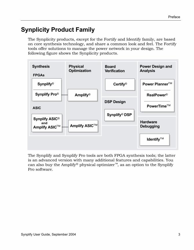
Synplicity Product FamilyThe Synplicity products, except for the Fortify and Identify family, are based on core synthesis technology, and share a common look and feel. The Fortify tools offer solutions to manage the power network in your design. The following figure shows the Synplicity products.
The Synplify and Synplify Pro tools are both FPGA synthesis tools; the latter is an advanced version with many additional features and capabilities. You can also buy the Amplify® physical optimizer™, as an option to the Synplify Pro software.
Synplify® Certify®
Synthesis Board Verification
Physical Optimization
FPGAs
ASIC
Synplify Pro® Amplify®
Power Design and Analysis
Power Planner™
RealPower®
Hardware Debugging
PowerTime™
Synplify ASIC®
Amplify ASIC™and
Amplify ASIC™
Synplify® DSP
DSP Design
Identify™
LO
Preface
4 Synplify User Guide, September 2004
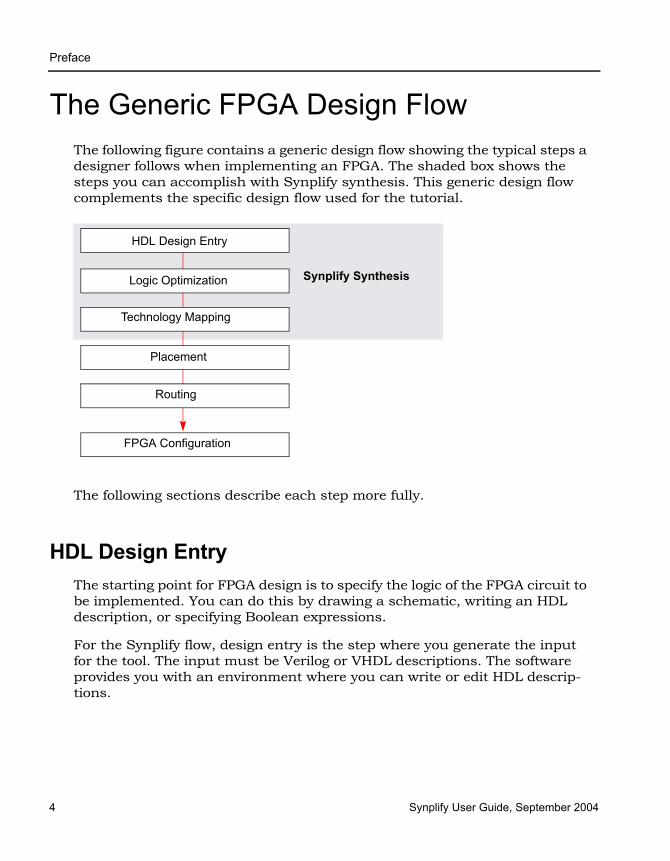
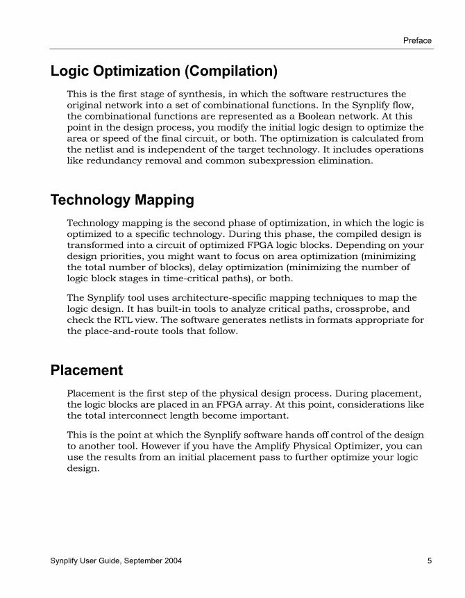
The Generic FPGA Design FlowThe following figure contains a generic design flow showing the typical steps a designer follows when implementing an FPGA. The shaded box shows the steps you can accomplish with Synplify synthesis. This generic design flow complements the specific design flow used for the tutorial.
The following sections describe each step more fully.
HDL Design EntryThe starting point for FPGA design is to specify the logic of the FPGA circuit to be implemented. You can do this by drawing a schematic, writing an HDL description, or specifying Boolean expressions.
For the Synplify flow, design entry is the step where you generate the input for the tool. The input must be Verilog or VHDL descriptions. The software provides you with an environment where you can write or edit HDL descrip-tions.
HDL Design Entry
Logic Optimization
Technology Mapping
Routing
Placement
FPGA Configuration
Synplify Synthesis
Preface
Synplify User Guide, September 2004 5
Logic Optimization (Compilation)This is the first stage of synthesis, in which the software restructures the original network into a set of combinational functions. In the Synplify flow, the combinational functions are represented as a Boolean network. At this point in the design process, you modify the initial logic design to optimize the area or speed of the final circuit, or both. The optimization is calculated from the netlist and is independent of the target technology. It includes operations like redundancy removal and common subexpression elimination.
Technology MappingTechnology mapping is the second phase of optimization, in which the logic is optimized to a specific technology. During this phase, the compiled design is transformed into a circuit of optimized FPGA logic blocks. Depending on your design priorities, you might want to focus on area optimization (minimizing the total number of blocks), delay optimization (minimizing the number of logic block stages in time-critical paths), or both.
The Synplify tool uses architecture-specific mapping techniques to map the logic design. It has built-in tools to analyze critical paths, crossprobe, and check the RTL view. The software generates netlists in formats appropriate for the place-and-route tools that follow.
PlacementPlacement is the first step of the physical design process. During placement, the logic blocks are placed in an FPGA array. At this point, considerations like the total interconnect length become important.
This is the point at which the Synplify software hands off control of the design to another tool. However if you have the Amplify Physical Optimizer, you can use the results from an initial placement pass to further optimize your logic design.

LO
Preface
6 Synplify User Guide, September 2004
RoutingRouting is the final step of the physical design process. At this stage, use the place-and-route tool to connect the placed logic blocks by assigning wire segments and choosing programmable switches.
FPGA ConfigurationIn this design phase, you configure the final FPGA chip and implement it.
AudienceThe Synplify software is targeted towards the FPGA system developer. It is assumed that you are knowledgeable about the following:
• Design synthesis
• RTL
• FPGAs
• Verilog/VHDL

Preface
Synplify User Guide, September 2004 7
Scope of the DocumentThis user guide is part of a document set, and is intended for use with the other documents in the set. It concentrates on describing how to use the Synplify software to accomplish typical tasks. This implies the following:
• The user guide only explains the options needed to do the typical tasks described in the manual. It does not describe every available command and option. For complete descriptions of all the command options and syntax, refer to the User Interface Commands chapter in the Synplify Reference Manual.
• The user guide contains task-based information. For a breakdown of how information is organized, see Getting Help, on page 1-10.
Starting the SoftwareThis section shows you how to get started with the Synplify software. It describes the following topics, but does not supersede the information in the installation instructions about licensing and installation:
• Getting Started, on page 1-7
• Using the License Wizard, on page 1-8
• Getting Help, on page 1-10
Getting Started1. If you have not already done so, install the Synplify software according to
the installation instructions.
2. Start the software.
– If you are working on a PC, select Programs->Synplicity->Synplify <version> from the Start button.
– If you are working on a UNIX platform, type this at the command line:
synplify
LO
Preface
8 Synplify User Guide, September 2004
The command starts the Synplify synthesis tool, and opens the Project window. If you have run the software before, the window displays the previous project. For more information about the interface, see the User Interface Overview chapter of the Synplify Reference Manual.
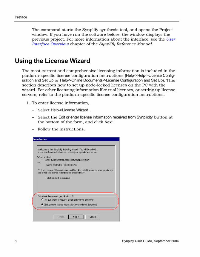
Using the License WizardThe most current and comprehensive licensing information is included in the platform-specific license configuration instructions (Help->Help->License Config-uration and Set Up or Help->Online Documents->License Configuration and Set Up). This section describes how to set up node-locked licenses on the PC with the wizard. For other licensing information like trial licenses, or setting up license servers, refer to the platform-specific license configuration instructions.
1. To enter license information,
– Select Help->License Wizard.
– Select the Edit or enter license information received from Synplicity button at the bottom of the form, and click Next.
– Follow the instructions.

Preface
Synplify User Guide, September 2004 9
2. To select a new floating license or change your current license,
– Pick Help->Preferred License Selection.
– Click on a license from the License Type list, and click Select.
– To automatically start the selected license the next time you start the software, select Save as default license type at the bottom of the window.
– Click Save and restart the software.
3. For Windows 98, Windows NT, and Windows 2000, install the sentinel driver. For detailed instructions, select Help->Online Documents and then click Windows License Configuration and Set Up. After the drive has been installed, restart the computer. You can now start the Synplify software.

LO
Preface
10 Synplify User Guide, September 2004
Getting HelpBefore you call Synplicity Support, look through the documented informa-tion. You can access the information online from the Help menu, or refer to the PDF version. The following table shows you how the information is organized.
For help with... Refer to the...
Using software features Synplify User Guide
How to... Synplify User Guide, application notes on the Synplicity support web site
Flow information Synplify User Guide, application notes on the Synplicity support web site
Error messages Online help (select Help->Error Messages)
Licensing License configuration information for your platform
Attributes and directives Synplify Reference Manual
Synthesis features Synplify Reference Manual
Language and syntax Synplify Reference Manual
Tcl syntax Online help (select Help->Tcl Help)
Tcl synthesis commands Synplify Reference Manual
Product updates Synplify Reference Manual (Web menu commands)
Preface
Synplify User Guide, September 2004 11
User Interface OverviewThe user interface (UI) consists of a main window, called the Project view, and specialized windows or views for different tasks. For details about each of the features, see the User Interface Overview chapter of the Synplify Reference Manual.
LO
Preface
12 Synplify User Guide, September 2004
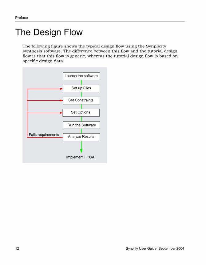
The Design FlowThe following figure shows the typical design flow using the Synplicity synthesis software. The difference between this flow and the tutorial design flow is that this flow is generic, whereas the tutorial design flow is based on specific design data.
Set up Files
Set Constraints
Run the Software
Launch the software
Analyze Results
Implement FPGA
Set Options
Fails requirements

Synplify User Guide, September 2004 1
C H A P T E R 2
File Setup
This chapter describes typical synthesis tasks, some of which are also in the tutorial. It covers the following:
• Setting Up HDL Source Files, on page 2-2
• Setting Up Project Files, on page 2-11
LO
Preface
2 Synplify User Guide, September 2004
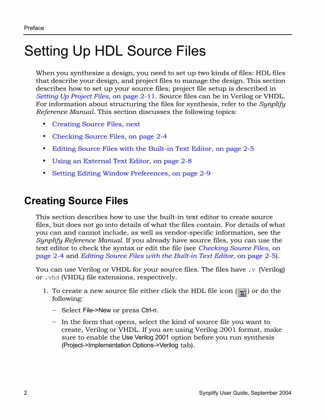
Setting Up HDL Source FilesWhen you synthesize a design, you need to set up two kinds of files: HDL files that describe your design, and project files to manage the design. This section describes how to set up your source files; project file setup is described in Setting Up Project Files, on page 2-11. Source files can be in Verilog or VHDL. For information about structuring the files for synthesis, refer to the Synplify Reference Manual. This section discusses the following topics:
• Creating Source Files, next
• Checking Source Files, on page 2-4
• Editing Source Files with the Built-in Text Editor, on page 2-5
• Using an External Text Editor, on page 2-8
• Setting Editing Window Preferences, on page 2-9
Creating Source FilesThis section describes how to use the built-in text editor to create source files, but does not go into details of what the files contain. For details of what you can and cannot include, as well as vendor-specific information, see the Synplify Reference Manual. If you already have source files, you can use the text editor to check the syntax or edit the file (see Checking Source Files, on page 2-4 and Editing Source Files with the Built-in Text Editor, on page 2-5).
You can use Verilog or VHDL for your source files. The files have .v (Verilog) or .vhd (VHDL) file extensions, respectively.
1. To create a new source file either click the HDL file icon ( ) or do the following:
– Select File->New or press Ctrl-n.
– In the form that opens, select the kind of source file you want to create, Verilog or VHDL. If you are using Verilog 2001 format, make sure to enable the Use Verilog 2001 option before you run synthesis (Project->Implementation Options->Verilog tab).

Preface
Synplify User Guide, September 2004 3
– Type a name and location for the file. Click OK.
A blank editing window opens with line numbers on the left. You can name it now by pressing Ctrl-s and naming the file.
2. Type the source information in the window, or cut and paste it. See Editing Source Files with the Built-in Text Editor, on page 2-5 for more information on working in the Editing window.
For the best synthesis results, check the Reference Manual and ensure that you are using the available constructs and vendor-specific attributes and directives effectively.
3. Save the file by selecting File->Save or the Save icon ( ). Use the correct extension for the type of file you created (.v or .vhd).
Once you have created a source file, you can check that you have the right syntax, as described in Checking Source Files, on page 2-4.
LO
Preface
4 Synplify User Guide, September 2004
Checking Source FilesThe software automatically checks the source files when it compiles them, but if you want to check your source code before synthesis, use this proce-dure to check your code. There are two kinds of checks you do in the synthesis software: syntax and synthesis.
1. Select the source files you want to check.
– To check a single file, open the file with File->Open or double-click the file in the Project window. For details of setting up the project file, see Setting Up Project Files, on page 2-11. If you have more than one file open and want to check only one of them, put your cursor in the appropriate file window to make sure that it is the active window .
– To check all the source files in a project, deselect all files in the project list, and make sure that none of the files are open in an active window. Go to the next step. If you have an active source file, the software only checks the active file.
2. To check the syntax, select Run->Syntax Check or press Shift+F7.
The software detects syntax errors like incorrect keywords and punctua-tion. It puts an exclamation mark next to files in the project list that have errors, and lists the number of warnings or notes found.
3. To run a synthesis check, select Run->Synthesis Check or press Shift+F8.
If there are hardware-related errors like incorrectly coded flip-flops, the software displays an exclamation mark next to the file name in the project list and lists the number of warnings or errors it found in the file.
4. Review the errors by doing one of the following:
– Check the log file for information about the error by selecting View -> Log File.
– Look at the relevant source code by double-clicking on the file with errors.
The Text Editor window opens the relevant source file, and highlights the code that caused the error message. Messages can be categorized as errors, warnings or notes. Review all of them and resolve all errors. Warnings are less serious than errors, but you must read through and understand them even if you do not resolve all of them. Notes generally contain information. For information on fixing errors, see Editing Source Files with the Built-in Text Editor, on page 2-5.

Preface
Synplify User Guide, September 2004 5
Editing Source Files with the Built-in Text EditorThe built-in text editor makes it easy to create your source code, view it, or edit it when you need to fix errors. If you want to use an external text editor, see Using an External Text Editor, on page 2-8.
1. Do one of the following to open a source file for viewing or editing:
– To automatically open the first file in the list with errors, press Ctrl-F5.
– To open a specific file, double-click the file in the Project window or use File->Open (Ctrl-o) and specify the source file.
The Text Editor window opens and displays the source file. Lines are numbered. Keywords are in blue, and comments in green. String values are in red. If you want to change these colors, see Setting Editing Window Preferences, on page 2-9.
2. To edit a file, type directly in the window.
This table summarizes common editing operations you might use. You can also use the keyboard shortcuts instead of the commands.
To... Do...
Cut, copy, and paste; undo, or redo an action
Select the command from the popup (hold down the right mouse button) or Edit menu.
Go to a specific line Press Ctrl-g or select Edit->Go To, type the line number, and click OK.
Find text Press Ctrl-f or select Edit ->Find. Type the text you want to find, and click OK.

LO
Preface
6 Synplify User Guide, September 2004
3. To cut and paste a section of a PDF document, select the T-shaped Text Select icon, highlight the text you need and copy and paste it into your file. The Text Select icon lets you select parts of the document.
4. To create and work with bookmarks in your file, see the following table.
Bookmarks are a convenient way to navigate long files or to jump to points in the code that you refer to often. You can use the icons in the Edit toolbar for these operations. If you cannot see the Edit toolbar on the far right of your window, resize some of the other toolbars.
Replace text Press Ctrl-h or select EditReplace. Type the text you want to find, and the text you want to replace it with. Click OK.
Complete a keyword Type enough characters to uniquely identify the keyword, and press Esc.
Indent text to the right Select the block, and press Tab.
Indent text to the left Select the block, and press Shift-Tab.
Change to upper case Select the text, and then select Edit->Advanced->Uppercase or press Ctrl-Shift-u.
Change to lower case Select the text, and then select Edit->Advanced->Lowercase or press Ctrl-u.
Add block comments Put the cursor at the beginning of the comment text, and select Edit->Advanced->Comment Code or press Alt-c.
Edit columns Press Alt, and use the left mouse button to select the column. On some platforms, you have to use the key to which the Alt functionality is mapped, like the Meta or diamond key.
To... Do...
Insert a bookmark
Click anywhere in the line you want to bookmark. Select EditToggle Bookmarks, press Ctrl-F2, or select the first icon in the Edit toolbar.The line number is highlighted to indicate that there is a bookmark at the beginning of that line.
To... Do...
Preface
Synplify User Guide, September 2004 7
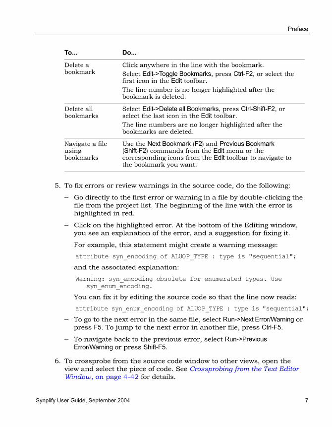
5. To fix errors or review warnings in the source code, do the following:
– Go directly to the first error or warning in a file by double-clicking the file from the project list. The beginning of the line with the error is highlighted in red.
– Click on the highlighted error. At the bottom of the Editing window, you see an explanation of the error, and a suggestion for fixing it.
For example, this statement might create a warning message:
attribute syn_encoding of ALUOP_TYPE : type is "sequential";
and the associated explanation:
Warning: syn_encoding obsolete for enumerated types. Use syn_enum_encoding.
You can fix it by editing the source code so that the line now reads:
attribute syn_enum_encoding of ALUOP_TYPE : type is "sequential";
– To go to the next error in the same file, select Run->Next Error/Warning or press F5. To jump to the next error in another file, press Ctrl-F5.
– To navigate back to the previous error, select Run->Previous Error/Warning or press Shift-F5.
6. To crossprobe from the source code window to other views, open the view and select the piece of code. See Crossprobing from the Text Editor Window, on page 4-42 for details.
Delete a bookmark
Click anywhere in the line with the bookmark. Select Edit->Toggle Bookmarks, press Ctrl-F2, or select the first icon in the Edit toolbar.The line number is no longer highlighted after the bookmark is deleted.
Delete all bookmarks
Select Edit->Delete all Bookmarks, press Ctrl-Shift-F2, or select the last icon in the Edit toolbar.The line numbers are no longer highlighted after the bookmarks are deleted.
Navigate a file using bookmarks
Use the Next Bookmark (F2) and Previous Bookmark (Shift-F2) commands from the Edit menu or the corresponding icons from the Edit toolbar to navigate to the bookmark you want.
To... Do...
LO
Preface
8 Synplify User Guide, September 2004
7. When you have fixed all the errors, select File->Save or click the Save icon to save the file.
To use the file, it must be part of a project. You can add it to a project automatically when you save it. You can also add it later, as described in Making Changes to a Project, on page 2-16. If it is already in a project, you can rerun synthesis.
Using an External Text EditorYou can now use an external text editor like vi or emacs instead of the built-in text editor. Do the following to enable an external text editor. For information about using the built-in text editor, see Editing Source Files with the Built-in Text Editor, on page 2-5.
1. Select Options->Editor Options and turn on the External Editor option.
2. Select the external editor, using the method appropriate to your operating system.
– If you are working on a PC platform, click the ...( Browse) button and select the external text editor executable.
– From a UNIX or Linux platform for a text editor that creates its own window, click the ... Browse button and select the external text editor executable.
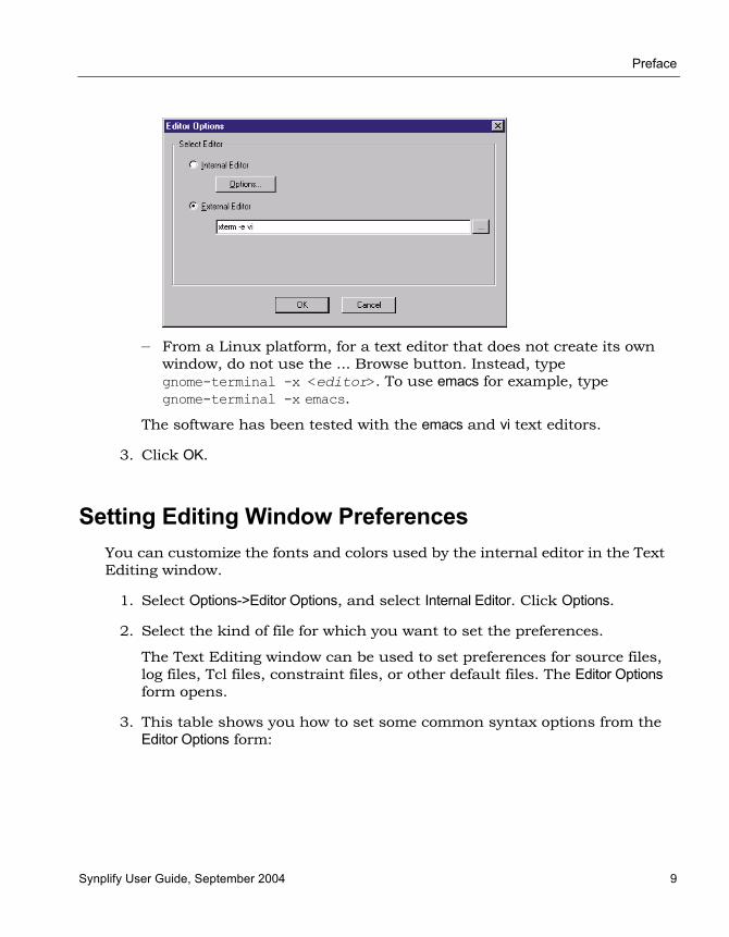
– From a UNIX platform for a text editor that does not create its own window, do not use the ... Browse button. Instead type xterm -e <editor>. The following figure shows VI specified as the external editor.
Preface
Synplify User Guide, September 2004 9
– From a Linux platform, for a text editor that does not create its own window, do not use the ... Browse button. Instead, type gnome-terminal -x <editor>. To use emacs for example, type gnome-terminal -x emacs.
The software has been tested with the emacs and vi text editors.
3. Click OK.
Setting Editing Window PreferencesYou can customize the fonts and colors used by the internal editor in the Text Editing window.
1. Select Options->Editor Options, and select Internal Editor. Click Options.
2. Select the kind of file for which you want to set the preferences.
The Text Editing window can be used to set preferences for source files, log files, Tcl files, constraint files, or other default files. The Editor Options form opens.
3. This table shows you how to set some common syntax options from the Editor Options form:

LO
Preface
10 Synplify User Guide, September 2004
4. Click OK on the Editor Options form.
To... Do This on the Editor Options form...
Set syntax color defaults
Click Syntax coloring.On the Syntax Coloring form, check Use syntax coloring.Set the colors you want for keywords, comments, quotes, and default text by clicking Foreground and Background and selecting colors from the palette. Click OK.
Define comment characters
Click Syntax coloring. On the Syntax Coloring form, type the comment start character(s) in the lower part of the form. Type the comment end characters if necessary.Click OK.
Make the text editorcase-sensitive
Click Syntax coloringOn the Syntax Coloring form, check Case Sensitive.Click OK.
Set fonts Click Fonts. On the Font form, set the font and the size.Click OK.
Set tabs Specify tab size.Specify whether spaces or tabs are to be used to define tabs. Set the display of a tab character.

Preface
Synplify User Guide, September 2004 11
Setting Up Project FilesFor a specific example on setting up a project file, refer to the tutorial. This section describes the following:
• Creating a Project File Without the Project Wizard, next
• Creating a Project File with the Project Wizard, on page 2-14
• Opening an Existing Project File, on page 2-15
• Making Changes to a Project, on page 2-16
• Setting Project View Display Preferences, on page 2-18
Creating a Project File Without the Project WizardYou must set up a project file for each project. A project contains the data needed for a particular design: the list of source files, the synthesis results file, and your device option settings. The following procedure shows you how to set up a project file using individual commands. For information about setting up a project file with the Project Wizard, see Creating a Project File with the Project Wizard, on page 2-14.
1. Start by selecting one of the following: File->Build Project, File->Open Project, or the P icon. Click New Project.
The Project window shows a new project. Click the Add File button, press F4, or select the Project->Add Source File command. The Select Files to Add to Project dialog box opens.
2. Add the source files to the project.
– Make sure the Look in field at the top of the form points to the right directory. The files are listed in the box. If you do not see the files, check that the Files of Type field is set to display the correct file type.

LO
Preface
12 Synplify User Guide, September 2004
– To add all the files in the directory at once, click the Add All button on the right side of the form. To add files individually, click on the file in the list and then click the Add button, or double-click the file name.
You can add all the files in the directory and then remove the ones you do not need with the Remove button.
– Click OK.
Your project window displays a new project file. If you click on the plus sign next to the project and expand it, you see the following:
– A folder with the source filesIf your files are not in a folder under the project directory, you can set this preference by selecting Options->Project View Options and checking the View project files in folders box. This separates one kind of file from another in the Project view by putting them in separate folders.

Preface
Synplify User Guide, September 2004 13
– The implementation, usually named rev_1. Implementations are revisions of your design within the context of the synthesis software, and do not replace external source code control software and processes. Each implementation has its own synthesis and device options and its own project-related files.
3. Check file order in the Project view. File order is especially important for VHDL files.
– For VHDL files, you can automatically order the files by selecting Run->Arrange VHDL Files. Alternatively, manually move the files in the Project view. Package files must be first on the list because they are compiled before they are used. If you have design blocks spread over many files, make sure you have the following file order: the file containing the entity must be first, followed by the architecture file, and finally the file with the configuration.
– In the Project view, check that the last file in the Project view is the top-level source file. Alternatively, you can specify the top-level file when you set the device options.
4. To add a third-party VHDL package library, do the following:
– Add the .vhd file to the design, as described in step 2.
– Right click the file in the Project view and select File Options, or select Project-> Set VHDL library. Specify a library name that is compatible with the simulators. For example, MYLIB.

LO
Preface
14 Synplify User Guide, September 2004
– Make sure that this package library is before the top-level design in the list of files in the Project view.
For information about setting Verilog and VHDL file options, see Setting Verilog and VHDL Options, on page 3-9. You can set these file options later, before running synthesis.
5. Select File->Save, type a name for the project, and click Save. The Project window reflects your changes.
6. To close a project file, select the Close Project button or File->Close Project.
Creating a Project File with the Project WizardThe easiest way to create a project file is to use the wizard, but you can also use individual commands for each step in the process of building a project file. See Creating a Project File Without the Project Wizard, on page 2-11 for details.
1. Click the P icon or select File->Open Project. Click Project Wizard in the form that opens.
The Project Wizard opens. It prompts you to fill out information.
2. Set Project Type to Synthesis, type a name for the project, and click Next.
3. Click Add Files. The Select Files to Add to Project dialog box opens.

Preface
Synplify User Guide, September 2004 15
4. Add the files as described in Creating a Project File Without the Project Wizard, on page 2-11.
5. Check file order. You can adjust the file order within the wizard or in the Project view. The following shows you how to use the wizard; for information about adjusting file order in the Project view and general information about VHDL file order, see Creating a Project File Without the Project Wizard, on page 2-11.
– To adjust file order within the wizard, select the file and use the arrows to move the file to the right position. For example, use the arrows to move the top-level source file to the last position. If you do not do this now, you must explicitly specify the top-level source file when you set the device options or move the file in the Project view.
– At this point, you can either click Finish, because you have finished setting up the project file, or click Next and set the source file and other options with the wizard. For details about these options, see Setting Implementation Options, on page 3-2.
6. To add a third-party VHDL package library, right-click in the Project view and select Project-> Set VHDL library. Specify a library name that is compatible with the simulators. See step 4 of the procedure described in Creating a Project File Without the Project Wizard, on page 2-11.
7. To close a project file, select the Close Project button or File->Close Project.
Opening an Existing Project FileThere are two ways to open a project file: the Open Project and the generic File->Open command.
1. If the project you want to open is one you worked on recently, you can select it directly: File->Recent Projects-> projectName.
2. Use one of the following methods to open any project file:
Move file up
Move file downDelete file

LO
Preface
16 Synplify User Guide, September 2004
The project opens in the Project window.
Making Changes to a ProjectTypically, you might have to add, delete, or replace files.
1. To add source or constraint files to a project, select the Add Files button or Project->Add Source File to open the Select Files to Add to Project dialog box. See Creating a Project File Without the Project Wizard, on page 2-11 for details.
2. To delete a file from a project, click the file in the Project window, and press the Delete key.
3. To replace a file in a project,
– Select the file you want to change in the Project window.
– Click the Change File button, or select Project->Change File.
– In the Source File dialog box that opens, set Look In to the directory where the new file is located. The new file must be of the same type as the file you want to replace.
– If you do not see your file listed, select the type of file you need from the Files of Type field.
– Double-click the file. The new file replaces the old one in the project list.
Open Project Command File->Open Command
Select File->Open Project orclick the P icon. To open a recent project, double-click it from the list of recent projects. Otherwise, click the Existing Project button to open the Open dialog box and select the project.
Select File->Open. Specify the correct directory in the Look In: field. Set File of Type to Project Files (*.prj). The box lists the project files. Double-click on the project you want to open.

Preface
Synplify User Guide, September 2004 17
4. To specify how project files are saved in the project, right click on a file in the Project view and select File Options. Set the Save File option to either Relative to Project or Absolute Path.
5. To check the time stamp on a file, right click on a file in the Project view and select File Options. Check the time that the file was last modified. Click OK.

LO
Preface
18 Synplify User Guide, September 2004
Setting Project View Display PreferencesYou can customize the organization and display of project files.
1. Select Options->Project View Options.
The Project View Options form opens.
2. To organize different kinds of input files in separate folders, check View Project Files in Folders.
Checking this option creates separate folders in the Project view for constraint files and source files.
Preface
Synplify User Guide, September 2004 19
3. Control file display with the following:
– Automatically display all the files, by checking Show Project Library. If this is unchecked, the Project view does not display files until you click on the plus symbol and expand the files in a folder.
– Check one of the boxes in the Project File Name Display section of the form to determine how filenames are displayed. You can display just the filename, the relative path, or the absolute path.
4. Control the output file display with the following:
– Check the Show all Files in Results Directory box to display all the output files generated after synthesis.
– Change output file organization by clicking in one of the header bars in the Implementation Results view. You can group the files by type or sort them according to the date they were last modified.
5. To view file information, select the file in the Project view, right-click, and select File Options. For example, you can check the date a file was modified.

LO
Preface
20 Synplify User Guide, September 2004
Synplify User Guide, September 2004 1
C H A P T E R 3
Constraints, Attributes, and Options
This chapter describes the typical options you set when working through the synthesis design flow. It covers the following:
• Setting Implementation Options, on page 3-2
• Setting Constraints in the SCOPE Window, on page 3-13
• Working with Constraint Files, on page 3-31
• Adding Attributes and Directives, on page 3-36
LO
Preface
2 Synplify User Guide, September 2004
Setting Implementation OptionsYou can set global options for your synthesis run, some of them technology-specific. This section covers the global options you set with the Implementation Options command. You can override the global setting by setting individual attributes or directives. For details of vendor-specific options, or attributes and directives, see the Synplify Reference Manual. For information about the Verilog and VHDL options, see This section discusses the following topics:
• Setting Device Options, next
• Setting Constraint and Optimization Options, on page 3-5
• Specifying Result Options, on page 3-6
• Specifying Timing Report Output, on page 3-8
• Setting Verilog and VHDL Options, on page 3-9
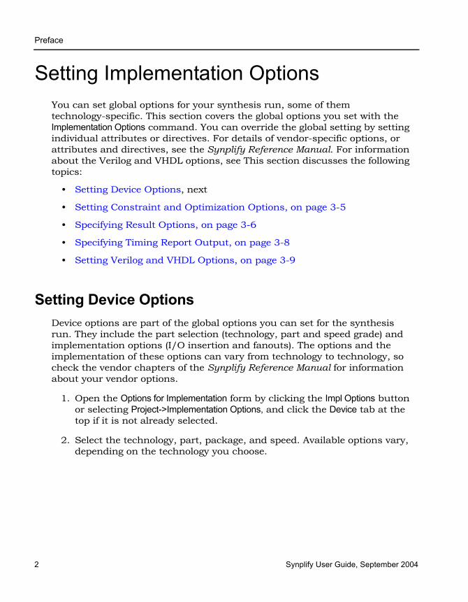
Setting Device OptionsDevice options are part of the global options you can set for the synthesis run. They include the part selection (technology, part and speed grade) and implementation options (I/O insertion and fanouts). The options and the implementation of these options can vary from technology to technology, so check the vendor chapters of the Synplify Reference Manual for information about your vendor options.
1. Open the Options for Implementation form by clicking the Impl Options button or selecting Project->Implementation Options, and click the Device tab at the top if it is not already selected.
2. Select the technology, part, package, and speed. Available options vary, depending on the technology you choose.
Preface
Synplify User Guide, September 2004 3
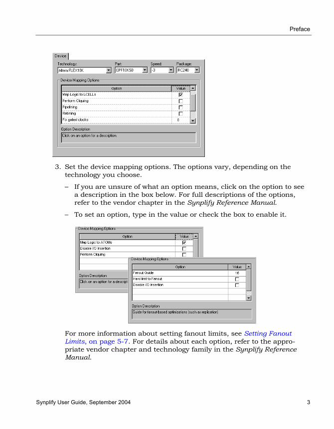
3. Set the device mapping options. The options vary, depending on the technology you choose.
– If you are unsure of what an option means, click on the option to see a description in the box below. For full descriptions of the options, refer to the vendor chapter in the Synplify Reference Manual.
– To set an option, type in the value or check the box to enable it.
For more information about setting fanout limits, see Setting Fanout Limits, on page 5-7. For details about each option, refer to the appro-priate vendor chapter and technology family in the Synplify Reference Manual.

LO
Preface
4 Synplify User Guide, September 2004
4. Set other options as described in Setting Constraint and Optimization Options, on page 3-5, Specifying Result Options, on page 3-6, Specifying Timing Report Output, on page 3-8, and Setting Verilog and VHDL Options, on page 3-9.
5. Click OK and run synthesis.
The software compiles and maps the design using the options you set.
6. To set device options with a script, use the set_option Tcl command.
The following table contains an alphabetical list of the device options on the form mapped to the equivalent Tcl commands. Because the options are technology-based, all the options will not apply to your design. All commands begin with set_option, followed by the syntax in the column as shown. Check the Synplify Reference Manual for the most comprehen-sive list of options for your vendor.
The following table shows typical device options.
Option Tcl Command (set_option...)
Disable I/O insertion -disable_io_insertion {true|false}
Fanout guide) -fanout_guide fanout_value
Fanout limit -fanout_limit limit
Fanout limit (hard) (Actel) -maxfan_hard {true|false}
Package -package pkg_name
Part -part part_name
Speed -speed_grade speed_grade
Technology -technology keyword

Preface
Synplify User Guide, September 2004 5
Setting Constraint and Optimization OptionsConstraint and optimization options are part of the global options you can set for the run. This section tells you how to set options like frequency and global optimization options like resource sharing. You can also set some of these options with the appropriate buttons on the UI.
1. Open the Options for Implementation form by clicking the Impl Options button or selecting Project->Implementation Options, and click the Options tab at the top.
2. Click the optimization options you want, either on the form or on the left panel. Your choices vary, depending on the technology. If an option is not available for your technology, it is grayed out. Setting the option in one place automatically updates it in the other.
The equivalent Tcl set_option command options are -frequency, -resource_sharing, and -symbolic_fsm_compiler.
For more information about the FSM compiler,see Using the Symbolic FSM Compiler, on page 5-17
3. Click the Constraints tab and specify the constraints you want to use.
– Specify the frequency. The equivalent Tcl set_option command is -frequency frequency_value. See Setting Constraints in the SCOPE Window, on page 3-13 for more information about constraints
– Check the constraints (.sdc) files you want to use in the project.
– If you do not want to use a constraint file that is currently in the project, click off the checkbox next to the file name. You can do the same thing in the Project view by right-clicking on the file, and selecting Remove from Project.
Implementation Options Form Option Panel in Project View

LO
Preface
6 Synplify User Guide, September 2004
4. Set other options as described in Setting Device Options, on page 3-2, Specifying Result Options, on page 3-6, Specifying Timing Report Output, on page 3-8, and Setting Verilog and VHDL Options, on page 3-9.
5. Click OK and run synthesis.
The software compiles and maps the design using the options you set.
Specifying Result OptionsThis section shows you how to specify criteria for the output of the synthesis run.
1. Open the Options for Implementation form by clicking the Impl Options button or selecting Project->Implementation Options, and click the Implementation Results tab at the top.
Implementation Options Form Option Panel in Project View
Preface
Synplify User Guide, September 2004 7
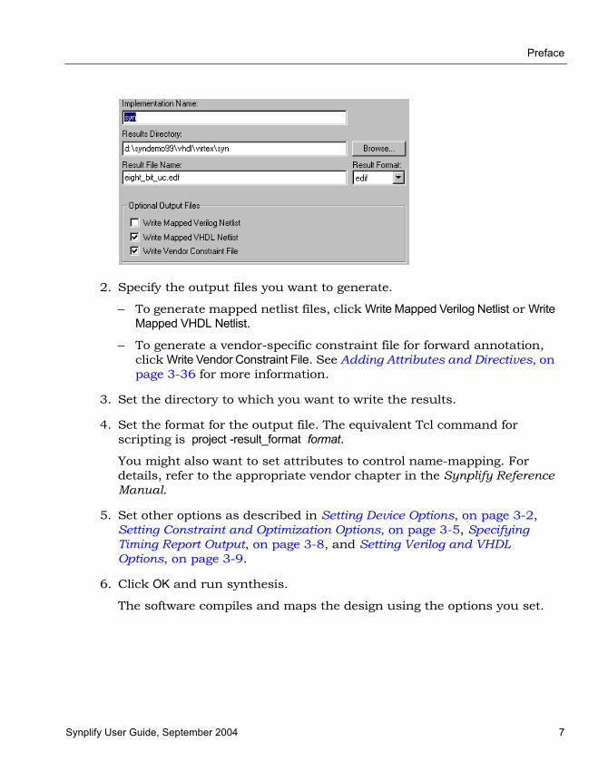
2. Specify the output files you want to generate.
– To generate mapped netlist files, click Write Mapped Verilog Netlist or Write Mapped VHDL Netlist.
– To generate a vendor-specific constraint file for forward annotation, click Write Vendor Constraint File. See Adding Attributes and Directives, on page 3-36 for more information.
3. Set the directory to which you want to write the results.
4. Set the format for the output file. The equivalent Tcl command for scripting is project -result_format format.
You might also want to set attributes to control name-mapping. For details, refer to the appropriate vendor chapter in the Synplify Reference Manual.
5. Set other options as described in Setting Device Options, on page 3-2, Setting Constraint and Optimization Options, on page 3-5, Specifying Timing Report Output, on page 3-8, and Setting Verilog and VHDL Options, on page 3-9.
6. Click OK and run synthesis.
The software compiles and maps the design using the options you set.

LO
Preface
8 Synplify User Guide, September 2004
Specifying Timing Report OutputYou can determine how much is reported in the timing report by setting the following options.
1. Open the Options for Implementation form by clicking the Impl Options button or selecting Project->Implementation Options, and click the Timing Report tab at the top.
2. Set the number of critical paths you want the software to report.
3. Specify the number of start and end points you want to see reported in the critical path sections.
4. Set other options as described in Setting Device Options, on page 3-2, Setting Constraint and Optimization Options, on page 3-5, Setting Verilog and VHDL Options, on page 3-9, and Specifying Result Options, on page 3-6.
5. Click OK and run synthesis.
The software synthesizes the design and generates a timing report according to the options you set.
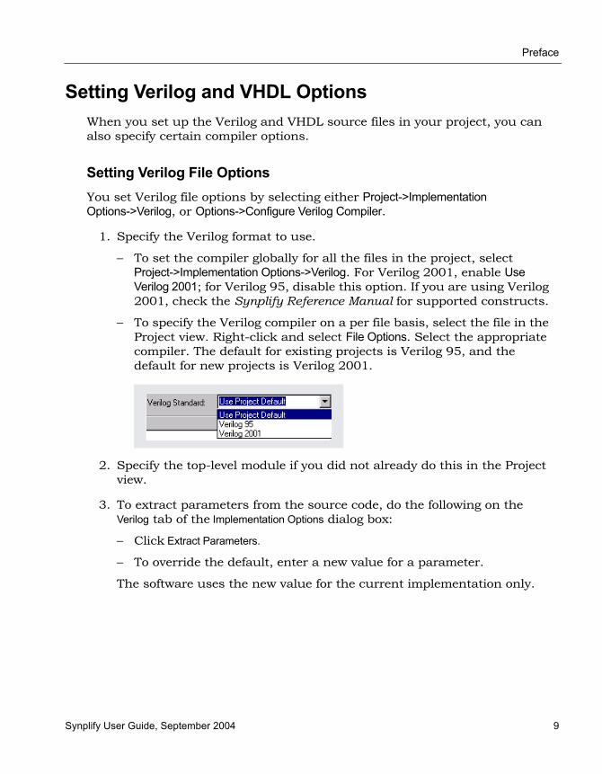
Preface
Synplify User Guide, September 2004 9
Setting Verilog and VHDL OptionsWhen you set up the Verilog and VHDL source files in your project, you can also specify certain compiler options.
Setting Verilog File OptionsYou set Verilog file options by selecting either Project->Implementation Options->Verilog, or Options->Configure Verilog Compiler.
1. Specify the Verilog format to use.
– To set the compiler globally for all the files in the project, select Project->Implementation Options->Verilog. For Verilog 2001, enable Use Verilog 2001; for Verilog 95, disable this option. If you are using Verilog 2001, check the Synplify Reference Manual for supported constructs.
– To specify the Verilog compiler on a per file basis, select the file in the Project view. Right-click and select File Options. Select the appropriate compiler. The default for existing projects is Verilog 95, and the default for new projects is Verilog 2001.
2. Specify the top-level module if you did not already do this in the Project view.
3. To extract parameters from the source code, do the following on the Verilog tab of the Implementation Options dialog box:
– Click Extract Parameters.
– To override the default, enter a new value for a parameter.
The software uses the new value for the current implementation only.

LO
Preface
10 Synplify User Guide, September 2004
4. Type in compiler directives, using spaces to separate the statements.
You can type in directives you would normally enter with ‘ifdef and ‘define statements in the code. For example, size=32 test_impl results in the software writing the following statements to the project file:
set_option -hdl_define -set "size=32 test_impl"
5. In the Include Path Order box, specify the search paths for the include commands in your project. Use the buttons in the upper right corner of the box to add, delete, or reorder the paths.
6. Set other options as described in Setting Device Options, on page 3-2, Setting Constraint and Optimization Options, on page 3-5, Specifying Result Options, on page 3-6, and Specifying Timing Report Output, on page 3-8. Click OK and run synthesis.
The software compiles and maps the design using the options you set.
Setting VHDL File OptionsYou set VHDL file options by selecting either Project->Implementation Options->VHDL, or Options->Configure VHDL Compiler.
Move file up
Move file downDelete file

Preface
Synplify User Guide, September 2004 11
For VHDL source, you can specify the following options:
• Top Level Entity – top level entity for the design.
Use this option when you want to specify a module that is not the actual top-level entity for HDL Analyst displaying and debugging in the schematic views.
• Default Enum Encoding – default encoding style for enumerated data types. See Defining State Machines in VHDL, on page 5-14 for information.
• Push Tristates – When enabled (default), tristates are pushed across process/block boundaries. For details, see Push Tristates Option, on page 3-38.
• Synthesis On/Off Implemented as Translate On/Off – This switch operates in conjunction with the synthesis_on and synthesis_off directives. When selected, these directives operate the same as translate_on/translate_off. If this switch is disabled, the synthesis_on/synthesis_off directives are ignored. See translate_off/translate_on, on page 8-103 in the Synplify Reference Manual for more information.
• Extract Generic Constants – Extracts generics from the top-level entity and displays them in the Generics table.
• Generics – Displays values from the Extract Generic Constants command. You can override the default and set a new value for the generic constant. The value is valid for the current implementation.
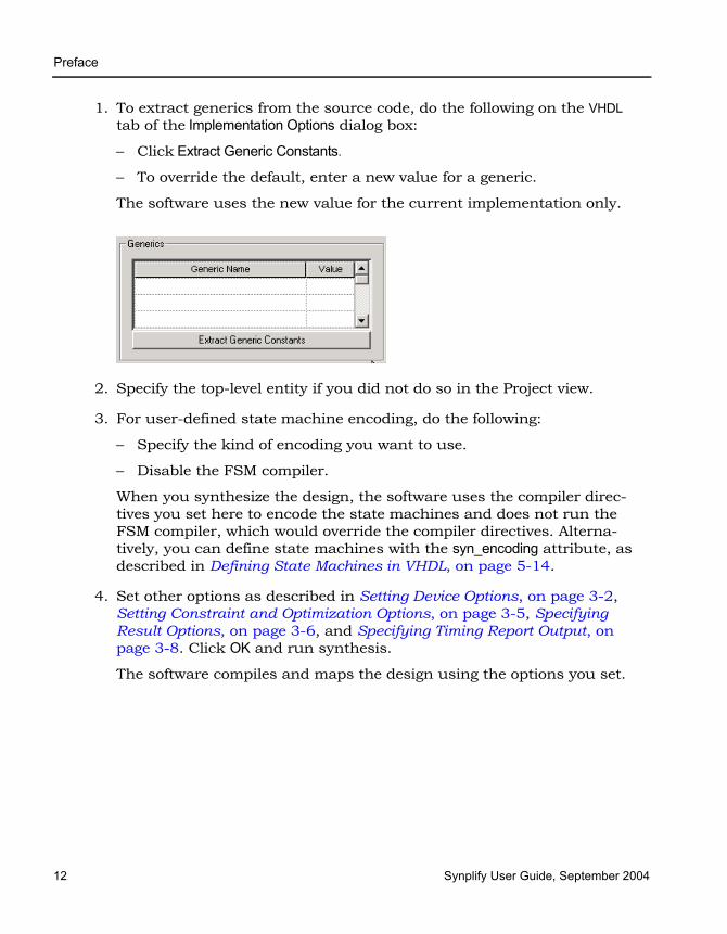
LO
Preface
12 Synplify User Guide, September 2004
1. To extract generics from the source code, do the following on the VHDL tab of the Implementation Options dialog box:
– Click Extract Generic Constants.
– To override the default, enter a new value for a generic.
The software uses the new value for the current implementation only.
2. Specify the top-level entity if you did not do so in the Project view.
3. For user-defined state machine encoding, do the following:
– Specify the kind of encoding you want to use.
– Disable the FSM compiler.
When you synthesize the design, the software uses the compiler direc-tives you set here to encode the state machines and does not run the FSM compiler, which would override the compiler directives. Alterna-tively, you can define state machines with the syn_encoding attribute, as described in Defining State Machines in VHDL, on page 5-14.
4. Set other options as described in Setting Device Options, on page 3-2, Setting Constraint and Optimization Options, on page 3-5, Specifying Result Options, on page 3-6, and Specifying Timing Report Output, on page 3-8. Click OK and run synthesis.
The software compiles and maps the design using the options you set.

Preface
Synplify User Guide, September 2004 13
Setting Constraints in the SCOPE WindowYou can use a text editor to create a constraint file as described in Working with Constraint Files, on page 3-31, but it is easier to use the SCOPE (Synthesis Constraint Optimization Environment) window, which provides a spreadsheet-like interface. The SCOPE interface is good for editing most constraints, but there are some constraints (like black box constraints) which can only be entered as directives in the source files. If you want to use a text editor to edit a constraint file, close the SCOPE window before editing the file, or you will overwrite results.
This section describes the following:
• Opening the SCOPE Window, next
• Entering and Editing Constraints in the SCOPE Window, on page 3-15
• Entering Default Constraints, on page 3-18
• Defining Clocks, on page 3-22
• Defining I/O Constraints, on page 3-26
• Defining False Paths, on page 3-27
• Defining From/To/Through for Timing Exceptions, on page 3-28
• Setting SCOPE Display Preferences, on page 3-30
You can also use the SCOPE window to add attributes. For more information, see Adding Attributes in the SCOPE Window, on page 3-38.
Opening the SCOPE WindowTo work with the SCOPE interface, you must have a compiled design so that the SCOPE table can access the design information. You can use the SCOPE window with an uncompiled design, but you have to type in entries manually because the software has no knowledge of the design.
1. To create a new constraint file, follow these steps:
– Compile the design (F7). If you do not compile the design, you can still use the SCOPE window, but you can not automatically initialize the clocks and I/O ports.

LO
Preface
14 Synplify User Guide, September 2004
– Open the SCOPE window by clicking the SCOPE icon in the toolbar ( ), pressing Ctrl-n, or selecting File -> New. If you use one of the latter two methods, select Constraint File (SCOPE) as the type of file to open. This opens the Initialize New Constraint File dialog box.
– Optionally, select the constraints to be initialized and click OK. If you started with a compiled design, setting these options automatically initializes the Clock and Inputs/Outputs tabs with the appropriate signals.
An empty SCOPE spreadsheet window opens. The tabs along the bottom
of the SCOPE window list the different kinds of constraints you can add. For each kind of constraint, the columns contain specific data.
You can now enter constraints directly or with the wizard. Refer to Entering and Editing Constraints in the SCOPE Window, on page 3-15 or Entering Default Constraints, on page 3-18.
File->New Ctrl-n

Preface
Synplify User Guide, September 2004 15
2. To open an existing file, do one of the following:
– Double-click the file from the project window.
– Press Ctrl-o or select File->Open. In the dialog box, set the kind of file you want to open to Constraint Files (SCOPE) (*.sdc), and double-click to select the file from the list.
The SCOPE window opens with the file you specified. For details about editing the file, see Entering and Editing Constraints in the SCOPE Window, on page 3-15. If you want to edit the Tcl file directly, see Working with Constraint Files, on page 3-31.
Entering and Editing Constraints in the SCOPE WindowFor manual constraints, the direct method is best suited for editing and entering individual constraints. If you are setting many constraints or defaults, use the wizard, as described in Entering Default Constraints, on page 3-18. You can use the wizard to enter default constraints, and then use the direct method to modify, add, or delete constraints.
1. Click the appropriate tab at the bottom of the window to enter the kind of constraint you want to create:
To define... Click...
Clock frequency for a clock signal output of clock divider logicA specific clock frequency that overrides the global frequency
Clock
Edge-to-edge clock delay that overrides the automatically calculated delay.
Clock to Clock
Input/output delays that model your FPGA input/output interface with the outside environment
Inputs/Outputs
Delay constraints for paths feeding into/out of registers Registers
Paths that require multiple clock cycles Multicycle paths
Paths to ignore for timing analysis (false paths) False Paths

LO
Preface
16 Synplify User Guide, September 2004
The SCOPE window displays columns appropriate to the kind of constraint you picked. You can now enter constraints using the wizard, or work directly in the SCOPE window.
2. Enter or edit constraints as follows:
– For attribute cells in the spreadsheet, click in the cell and select from the pulldown list of available choices.
– For object cells in the spreadsheet, click in the cell and select from the pulldown list. When you select from the list, the objects automatically have the proper prefixes in the SCOPE window.
Alternatively, you can drag and drop an object from an HDL Analyst view into the cell, or type in a name. If you drag a bus, the software enters the whole bus (busA). To enter busA[3:0], select the appropriate bus bits before you drag and drop them. If you drag and drop or type a name, make sure that the object has the proper prefix:
– For cells with values, type in the value or select from the pulldown list.
Maximum delay for paths Max Delay Paths
Attributes, like syn_reference_clock, that were not entered in the source files
Attributes
Place and route tool constraintsOther constraints not used for synthesis, but which are passed to other tools. For example, multiple clock cycles from a register or input pin to a register or output pin
Other
Prefix Description
v: view object (for a module)
i: instance
p: port
b: bit slice of a port
n: internal net
To define... Click...
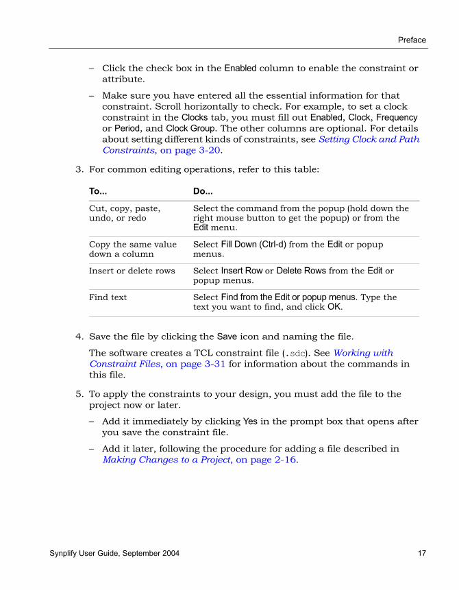
Preface
Synplify User Guide, September 2004 17
– Click the check box in the Enabled column to enable the constraint or attribute.
– Make sure you have entered all the essential information for that constraint. Scroll horizontally to check. For example, to set a clock constraint in the Clocks tab, you must fill out Enabled, Clock, Frequency or Period, and Clock Group. The other columns are optional. For details about setting different kinds of constraints, see Setting Clock and Path Constraints, on page 3-20.
3. For common editing operations, refer to this table:
4. Save the file by clicking the Save icon and naming the file.
The software creates a TCL constraint file (.sdc). See Working with Constraint Files, on page 3-31 for information about the commands in this file.
5. To apply the constraints to your design, you must add the file to the project now or later.
– Add it immediately by clicking Yes in the prompt box that opens after you save the constraint file.
– Add it later, following the procedure for adding a file described in Making Changes to a Project, on page 2-16.
To... Do...
Cut, copy, paste, undo, or redo
Select the command from the popup (hold down the right mouse button to get the popup) or from the Edit menu.
Copy the same value down a column
Select Fill Down (Ctrl-d) from the Edit or popup menus.
Insert or delete rows Select Insert Row or Delete Rows from the Edit or popup menus.
Find text Select Find from the Edit or popup menus. Type the text you want to find, and click OK.
LO
Preface
18 Synplify User Guide, September 2004
Entering Default ConstraintsThe wizard is best for entering a number of constraints or for setting defaults manually. To edit or set individual constraints, or create constraints in the Other tab, work directly in the SCOPE window (Setting Clock and Path Constraints, on page 3-20).The following procedure shows you two methods to enter defaults. The quick method, in step 1, is only appropriate for certain kinds of constraints. The rest of the steps show you how to use the wizard to enter other SCOPE constraints.
1. To quickly generate defaults in the Clocks or Inputs/Outputs tabs without the wizard, follow these steps. This method does not work for other constraints.
– Click on the Clocks or Inputs/Outputs tabs, and select Edit->Insert Quick. A new row is inserted at the top of the spreadsheet.
– Select the objects you want from the list.
– Enter the values you want, and enable the constraint.
– Save the constraint file and add it to the project.
2. To generate defaults with the wizard, follow the rest of these steps. Select a tab in the SCOPE window and then select Edit->Insert Wizard or press Ctrl-w to start the wizard.

Preface
Synplify User Guide, September 2004 19
The wizard guides you through two dialog boxes, which vary slightly depending on the kind of constraints you want to set.
3. In the first dialog box, select the design objects to which you want to attach the constraints.
– Move objects to the selected list by either using wildcards, or highlighting objects in the unselected list and using the arrow buttons to move them. If there are no objects in the Unselected box, disable the Exclude Duplicates option.
– Click Next.
4. In the second dialog box, set defaults for the selected objects.
– Enable or disable the constraints.
– Set the default value.
– Click Finish.

LO
Preface
20 Synplify User Guide, September 2004
When you are done, the constraints appear in the SCOPE window. To modify or add to them, do so directly in the SCOPE window (refer to Entering and Editing Constraints in the SCOPE Window, on page 3-15).
5. To apply the constraints, add the file to the project according to the procedure described in Making Changes to a Project, on page 2-16. The constraints file has a .sdc extension. See Working with Constraint Files, on page 3-31 for more information about constraint files.
Setting Clock and Path ConstraintsThe following table summarizes how to set different clock and path constraints from the SCOPE window. For information about setting attributes, see Adding Attributes in the SCOPE Window, on page 3-38. For information about setting default constraints, see Entering Default Constraints, on page 3-18.
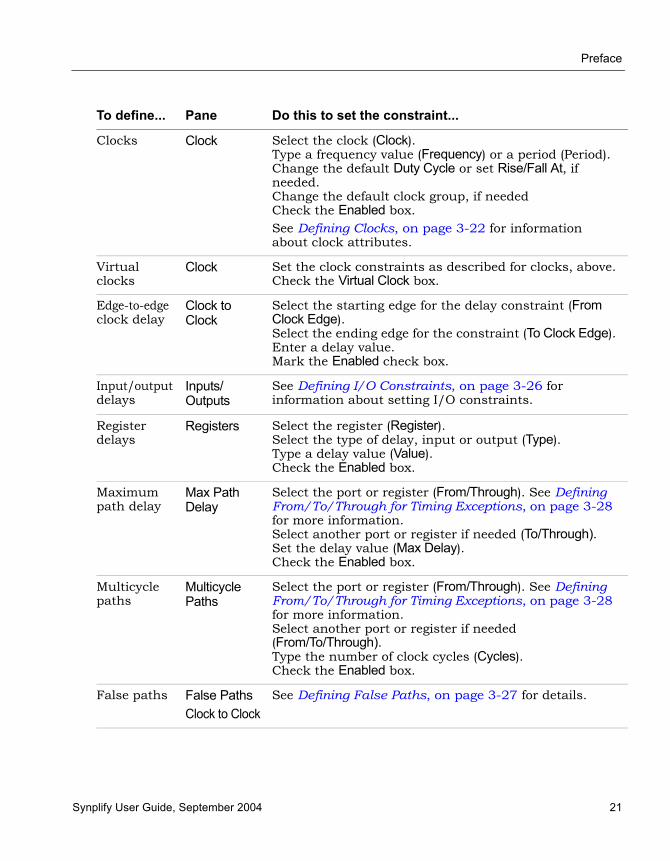
Preface
Synplify User Guide, September 2004 21
To define... Pane Do this to set the constraint...
Clocks Clock Select the clock (Clock).Type a frequency value (Frequency) or a period (Period). Change the default Duty Cycle or set Rise/Fall At, if needed. Change the default clock group, if neededCheck the Enabled box. See Defining Clocks, on page 3-22 for information about clock attributes.
Virtual clocks
Clock Set the clock constraints as described for clocks, above.Check the Virtual Clock box.
Edge-to-edge clock delay
Clock to Clock
Select the starting edge for the delay constraint (From Clock Edge).Select the ending edge for the constraint (To Clock Edge).Enter a delay value.Mark the Enabled check box.
Input/output delays
Inputs/Outputs
See Defining I/O Constraints, on page 3-26 for information about setting I/O constraints.
Register delays
Registers Select the register (Register).Select the type of delay, input or output (Type).Type a delay value (Value).Check the Enabled box.
Maximum path delay
Max Path Delay
Select the port or register (From/Through). See Defining From/To/Through for Timing Exceptions, on page 3-28 for more information. Select another port or register if needed (To/Through).Set the delay value (Max Delay).Check the Enabled box.
Multicycle paths
Multicycle Paths
Select the port or register (From/Through). See Defining From/To/Through for Timing Exceptions, on page 3-28 for more information. Select another port or register if needed (From/To/Through). Type the number of clock cycles (Cycles).Check the Enabled box.
False paths False PathsClock to Clock
See Defining False Paths, on page 3-27 for details.
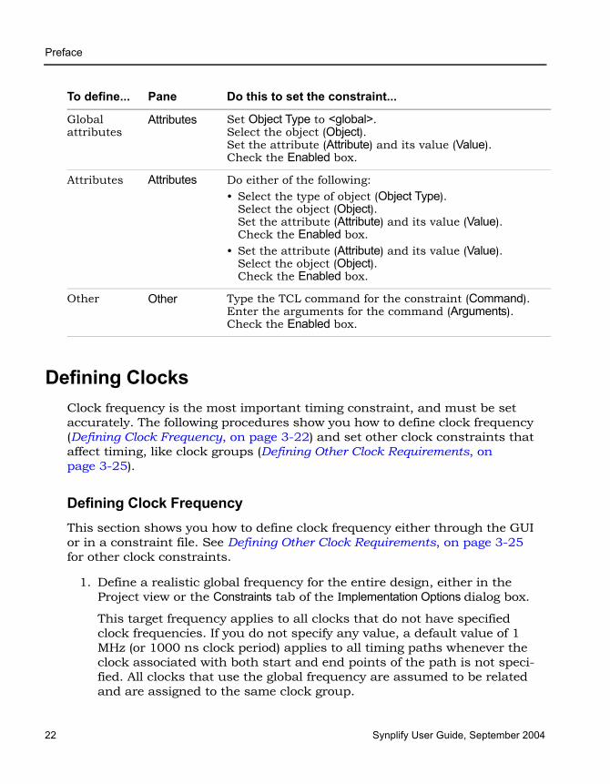
LO
Preface
22 Synplify User Guide, September 2004
Defining ClocksClock frequency is the most important timing constraint, and must be set accurately. The following procedures show you how to define clock frequency (Defining Clock Frequency, on page 3-22) and set other clock constraints that affect timing, like clock groups (Defining Other Clock Requirements, on page 3-25).
Defining Clock FrequencyThis section shows you how to define clock frequency either through the GUI or in a constraint file. See Defining Other Clock Requirements, on page 3-25 for other clock constraints.
1. Define a realistic global frequency for the entire design, either in the Project view or the Constraints tab of the Implementation Options dialog box.
This target frequency applies to all clocks that do not have specified clock frequencies. If you do not specify any value, a default value of 1 MHz (or 1000 ns clock period) applies to all timing paths whenever the clock associated with both start and end points of the path is not speci-fied. All clocks that use the global frequency are assumed to be related and are assigned to the same clock group.
Global attributes
Attributes Set Object Type to <global>.Select the object (Object).Set the attribute (Attribute) and its value (Value).Check the Enabled box.
Attributes Attributes Do either of the following:• Select the type of object (Object Type).
Select the object (Object).Set the attribute (Attribute) and its value (Value).Check the Enabled box.
• Set the attribute (Attribute) and its value (Value).Select the object (Object).Check the Enabled box.
Other Other Type the TCL command for the constraint (Command).Enter the arguments for the command (Arguments).Check the Enabled box.
To define... Pane Do this to set the constraint...
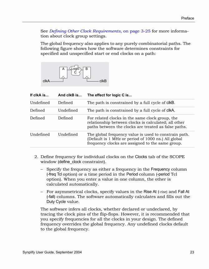
Preface
Synplify User Guide, September 2004 23
See Defining Other Clock Requirements, on page 3-25 for more informa-tion about clock group settings.
The global frequency also applies to any purely combinatorial paths. The following figure shows how the software determines constraints for specified and unspecified start or end clocks on a path:
2. Define frequency for individual clocks on the Clocks tab of the SCOPE window (define_clock constraint).
– Specify the frequency as either a frequency in the Frequency column (-freq Tcl option) or a time period in the Period column (-period Tcl option). When you enter a value in one column, the other is calculated automatically.
– For asymmetrical clocks, specify values in the Rise At (-rise) and Fall At (-fall) columns. The software automatically calculates and fills out the Duty Cycle value.
The software infers all clocks, whether declared or undeclared, by tracing the clock pins of the flip-flops. However, it is recommended that you specify frequencies for all the clocks in your design. The defined frequency overrides the global frequency. Any undefined clocks default to the global frequency.
If clkA is... And clkB is... The effect for logic C is...
Undefined Defined The path is constrained by a full cycle of clkB.
Defined Undefined The path is constrained by a full cycle of clkA.
Defined Defined For related clocks in the same clock group, the relationship between clocks is calculated; all other paths between the clocks are treated as false paths.
Undefined Undefined The global frequency value is used to constrain path. (Default is 1 MHz or period of 1000 ns.) All global frequency clocks are assigned to the same group.
BA
clkA clkB
LogicC

LO
Preface
24 Synplify User Guide, September 2004
3. Define internal clock frequencies (clocks generated internally) on the SCOPE Clocks tab (define_clock constraint). Apply the constraint according to the source of the internal clock.
4. For signals other than clocks, define frequencies with the syn_reference_clock attribute. You can add this attribute on the SCOPE Attributes tab.
You might need to do this if your design uses an enable signal as a clocking signal because of limited clocking resources. If the enable is slower than the clock, defining the enable frequency separately instead slowing down the clock frequency ensures more accuracy. If you slow down the clock frequency, it affects all other registers driven by the clock, and can result in longer run times as the tool tries to optimize a non-critical path.
Define this attribute as follows:
– Define a dummy clock on the Clocks tab (define_clock constraint).
– Add the syn_reference_clock attribute (Attributes tab) to the affected registers to apply the clock. In the constraint file, you can use the Find command to find all registers enabled by a particular signal and then apply the attribute:
define_clock -virtual dummy -period 40.0 define_attribute {find -reg -enable en40}
syn_reference_clock dummy
5. After synthesis, check the Performance Summary section of the log file for a list of all the defined and inferred clocks in the design.
Source Add SCOPE constraint/define_clock to...
Register Register.
Instance, like a PLL or clock DLL
Instance. If the instance has more than one clock output, apply the clock constraints to each of the output nets, making sure to use the n: prefix (to signify a net) in the SCOPE table.
Combinatorial logic Net. Make sure to use the n: prefix in the SCOPE interface.

Preface
Synplify User Guide, September 2004 25
Defining Other Clock RequirementsBesides clock frequency (described in Defining Clock Frequency, on page 3-22), you can also set other clock requirements, as follows:
1. If you have limited clock resources, define clocks that do not need a clock buffer by attaching the syn_noclockbuf attribute to an individual port, or the entire module/architecture.
2. Define the relationship between clocks by setting clock domains. By default, all clocks are in default_clkgroup. All inferred and other clocks that use the global frequency are in the same clock group.
– On the SCOPE Clocks tab, group related clocks by putting them into the same clock group. Use the Clock Group field to assign all related clocks to the same clock group.
– Make sure that unrelated clocks are in different clock groups. If you do not, the software calculates timing paths between unrelated clocks in the same clock group, instead of treating them as false paths.
The software does not check design rules, so it is best to define the relationship between clocks as completely as possible.
3. Define all gated clocks with the define_clock constraint.
Avoid using gated clocks to eliminate clock skew. If possible, move the logic to the data pin instead of using gated clocks. If you do use gated clocks, you must define them explicitly, because the software does not propagate the frequency of clock ports to gated clocks.
To define a gated clock, attach the define_clock constraint to the clock source, as described above for internal clocks. To attach the constraint to a keepbuf (a keepbuf is a placeholder instance for clocks generated from combinatorial logic), do the following:
– Attach the syn_keep attribute to the gated clock to ensure that it retains the same name through changes to the RTL code.
– Attach the define_clock constraint to the keepbuf generated for the gated clock.
4. Specify edge-to-edge clock delays on the Clock to Clock tab (define_clock_delay).
5. After synthesis, check the Performance Summary section of the log file for a list of all the defined and inferred clocks in the design.

LO
Preface
26 Synplify User Guide, September 2004
Defining I/O ConstraintsIn addition to setting I/O delays in the SCOPE window as described in Setting Clock and Path Constraints, on page 3-20, you can also set the Use clock period for unconstrained IO option.
1. Open the SCOPE window, click Inputs/Outputs, and select the port (Port).You can set the constraint for
– All inputs and outputs (globally in the top-level netlist)
– For a whole bus
– For single bits
You can specify multiple constraints for the same port. The software applies all the constraints; the tightest constraint determines the worst slack. If there are multiple constraints from different levels, the most specific overrides the more global. For example, if there are two bit constraints and two port constraints, the two bit constraints override the two port constraints for that bit. The other bits get the two port constraints.
2. Specify the constraint value in the SCOPE window:
– Select the type of delay: input or output (Type).
– Type a delay value (Value).
– Check the Enabled box, and save the constraint file in the project.
Make sure to specify explicit constraints for each I/O path you want to constrain.
3. To determine how the I/O constraints are used during synthesis, do the following:
– Select Project->Implementation Options, and click Constraints.
– To use only the explicitly defined constraints, enable Use clock period for unconstrained IO.
– To synthesize with all the constraints, using the clock period for all I/O paths that do not have an explicit constraint, disable Use clock period for unconstrained IO.
– Synthesize the design. When you forward-annotate the constraints, the constraints used for synthesis are forward-annotated.

Preface
Synplify User Guide, September 2004 27
Defining False PathsYou define false paths by setting constraints explicitly on the False Paths tab or implicitly on the Clock or Clock to Clock tabs. You can also define false paths with the corresponding define_false_path, define_clock, and define_clock_delay Tcl commands.
1. To define a false path between ports or registers, select the SCOPE False Paths tab, and do the following:
– Select the port or register (From/To/Through). See Defining From/To/Through for Timing Exceptions, on page 3-28 for more information.
– Select another port or register if needed (From/ To/Through).
– Check the Enabled box.
The software treats this is as an explicit false constraint and assigns it the highest priority. Any other constraints on this path are ignored.
2. To define a false path between two clock edges, select the SCOPE Clock to Clock tab, and do the following:
– Specify one clock as the starting clock edge (From Clock Edge).See Defining From/To/Through for Timing Exceptions, on page 3-28 for more information.
– Specify the other clock as the ending clock edge (To Clock Edge).
– Click in the Delay column, and select false.
– Mark the Enabled check box.
Use this technique to specify a false path between any two clocks, regardless of whether their clock groups. This constraint can be overridden by a maximum delay constraint on the same path.
3. To define a false path between two clocks, select the SCOPE Clocks tab, and assign the clocks to different clock groups:
The software implicitly assumes a false path between clocks in different clock groups. This false path constraint can be overridden by a maximum path delay constraint, or with an explicit constraint as described in the next step.
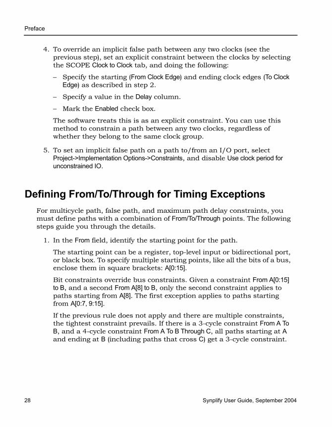
LO
Preface
28 Synplify User Guide, September 2004
4. To override an implicit false path between any two clocks (see the previous step), set an explicit constraint between the clocks by selecting the SCOPE Clock to Clock tab, and doing the following:
– Specify the starting (From Clock Edge) and ending clock edges (To Clock Edge) as described in step 2.
– Specify a value in the Delay column.
– Mark the Enabled check box.
The software treats this is as an explicit constraint. You can use this method to constrain a path between any two clocks, regardless of whether they belong to the same clock group.
5. To set an implicit false path on a path to/from an I/O port, select Project->Implementation Options->Constraints, and disable Use clock period for unconstrained IO.
Defining From/To/Through for Timing ExceptionsFor multicycle path, false path, and maximum path delay constraints, you must define paths with a combination of From/To/Through points. The following steps guide you through the details.
1. In the From field, identify the starting point for the path.
The starting point can be a register, top-level input or bidirectional port, or black box. To specify multiple starting points, like all the bits of a bus, enclose them in square brackets: A[0:15].
Bit constraints override bus constraints. Given a constraint From A[0:15] to B, and a second From A[8] to B, only the second constraint applies to paths starting from A[8]. The first exception applies to paths starting from A[0:7, 9:15].
If the previous rule does not apply and there are multiple constraints, the tightest constraint prevails. If there is a 3-cycle constraint From A To B, and a 4-cycle constraint From A To B Through C, all paths starting at A and ending at B (including paths that cross C) get a 3-cycle constraint.

Preface
Synplify User Guide, September 2004 29
2. In the To field, identify the ending point for the path.
The ending point can be a register, top-level output or bidirectional port, or black box. To specify multiple ending points, like all the bits of a bus, enclose them in square brackets: B[0:15]. In the case of multiple constraints, the priority rules described in the previous step apply.
If you specify multiple start points and multiple end points such as From A[0:15] to B[0:15], the constraint applies from any start point to any end point. In this example, the exception applies to all 16 * 16 = 256 combina-tions of start/end points.
3. For a single through point, specify the net name in the Through field.
This constraint applies to any path passing through regs_mem[2].
define_path_delay -through n:regs_mem[2]
4. To specify a list of through points, specify the nets in the Through field.
The constraint works as an OR function and applies to any path passing through any of the specified nets. The following constraint is applied to any path through regs_mem[2] OR prgcntr.pc[7] OR dmux.alub[0]:
define_path_delay -through {n:regs_mem[2], n:prgcntr.pc[7], n:dmux.alub[0]} -max 5
You can only specify one list of points.
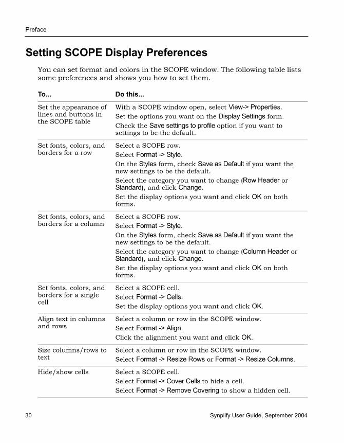
LO
Preface
30 Synplify User Guide, September 2004
Setting SCOPE Display PreferencesYou can set format and colors in the SCOPE window. The following table lists some preferences and shows you how to set them.
To... Do this...
Set the appearance of lines and buttons in the SCOPE table
With a SCOPE window open, select View-> Properties.Set the options you want on the Display Settings form. Check the Save settings to profile option if you want to settings to be the default.
Set fonts, colors, and borders for a row
Select a SCOPE row.Select Format -> Style.On the Styles form, check Save as Default if you want the new settings to be the default. Select the category you want to change (Row Header or Standard), and click Change.Set the display options you want and click OK on both forms.
Set fonts, colors, and borders for a column
Select a SCOPE row.Select Format -> Style.On the Styles form, check Save as Default if you want the new settings to be the default. Select the category you want to change (Column Header or Standard), and click Change.Set the display options you want and click OK on both forms.
Set fonts, colors, and borders for a single cell
Select a SCOPE cell.Select Format -> Cells.Set the display options you want and click OK.
Align text in columns and rows
Select a column or row in the SCOPE window. Select Format -> Align.Click the alignment you want and click OK.
Size columns/rows to text
Select a column or row in the SCOPE window.Select Format -> Resize Rows or Format -> Resize Columns.
Hide/show cells Select a SCOPE cell.Select Format -> Cover Cells to hide a cell.Select Format -> Remove Covering to show a hidden cell.

Preface
Synplify User Guide, September 2004 31
Working with Constraint FilesConstraint files are text files that are automatically generated by the SCOPE interface (see Setting Constraints in the SCOPE Window, on page 3-13), or which you create manually with a text editor. They contain Tcl commands or attributes that constrain the synthesis run. Alternatively, you can set constraints in the source code, but it is not the preferred method.
This section contains information about
• When to Use Constraint Files over Source Code, on page 3-31
• Tcl Syntax Guidelines for Constraint Files, on page 3-32
• Using a Text Editor for Constraint Files, on page 3-33
• Adding Attributes and Directives, on page 3-36
When to Use Constraint Files over Source CodeYou can add constraints in constraint files (generated by SCOPE interface or entered in a text editor) or in the source code. In general, it is better to use constraint files, because you do not have to recompile for the constraints to take effect. It also makes your source code more portable.
However, if you have black box timing constraints (syn_tco, syn_tpd, syn_tsu), you must enter them in the source code. Unlike attributes, directives can only be added to the source code, not to constraint files. See Adding Attributes and Directives, on page 3-36 for more information on adding directives to source code.
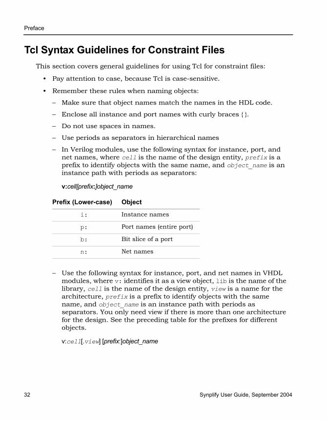
LO
Preface
32 Synplify User Guide, September 2004
Tcl Syntax Guidelines for Constraint FilesThis section covers general guidelines for using Tcl for constraint files:
• Pay attention to case, because Tcl is case-sensitive.
• Remember these rules when naming objects:
– Make sure that object names match the names in the HDL code.
– Enclose all instance and port names with curly braces { }.
– Do not use spaces in names.
– Use periods as separators in hierarchical names
– In Verilog modules, use the following syntax for instance, port, and net names, where cell is the name of the design entity, prefix is a prefix to identify objects with the same name, and object_name is an instance path with periods as separators:
v:cell[prefix:]object_name
– Use the following syntax for instance, port, and net names in VHDL modules, where v: identifies it as a view object, lib is the name of the library, cell is the name of the design entity, view is a name for the architecture, prefix is a prefix to identify objects with the same name, and object_name is an instance path with periods as separators. You only need view if there is more than one architecture for the design. See the preceding table for the prefixes for different objects.
v:cell[.view] [prefix:]object_name
Prefix (Lower-case) Object
i: Instance names
p: Port names (entire port)
b: Bit slice of a port
n: Net names

Preface
Synplify User Guide, September 2004 33
• Use the * and ? wildcards to match names. The asterisk matches any number of characters, and the question mark matches a single character. These characters do not match periods that are used as hierarchy separators. For example, you can use the following to identify all bits of the statereg instance in the statemod module:
statemod | i: statereg[*]
Using a Text Editor for Constraint FilesThis section shows you how to manually create a Tcl constraint file. The software automatically creates this file if you use the SCOPE interface to enter the constraints. The Tcl constraint file only contains general timing constraints. Black box constraints must be entered in the source code. For details of the Tcl commands, refer to the Synplify Reference Manual. For additional information, see When to Use Constraint Files over Source Code, on page 3-31.
1. Open a file for editing.
– Make sure you have closed the SCOPE window, or you could overwrite previous constraints.
– To create a new file, select File->New, and select the Constraint File (SCOPE) option. Type a name for the file and click OK.
– To edit an existing file, select File->Open, set the Files of Type filter to Constraint Files (.sdc) and open the file you want.
2. Follow the syntax guidelines in Tcl Syntax Guidelines for Constraint Files, on page 3-32.

LO
Preface
34 Synplify User Guide, September 2004
3. Enter the timing constraints you need. For the syntax, see the Reference Manual. If you have black box timing constraints, you must enter them in the source code.
To define... Use...
Clock frequencies define_clock. See Defining Clocks, on page 3-22 for additional information.
Clock frequency other than the one implied by the signal on the clock pin
syn_reference_clock (attribute). See Defining Clocks, on page 3-22 for additional information
Clock domains with asymmetric duty cycles
define_clock. See Defining Clocks, on page 3-22 for additional information
Edge-to-edge clock delays define_clock_delay. See Defining Clocks, on page 3-22 for additional information
Speed up paths feeding into a register
define_reg_input_delay.
Speed up paths coming from a register
define_reg_output_delay.
Input delays from outside the FPGA
define_input_delay. See Defining I/O Constraints, on page 3-26 for additional information
Output delays from your FPGA
define_output_delay. See Defining I/O Constraints, on page 3-26 for additional information
Paths with multiple clock cycles
define_multicycle_path. See Defining From/To/Through for Timing Exceptions, on page 3-28 for additional information
False paths (certain technologies)
define_false_path. See Defining False Paths, on page 3-27 for additional information
Path delays define_path_delay. See Defining From/To/Through for Timing Exceptions, on page 3-28 for additional information

Preface
Synplify User Guide, September 2004 35
The following code excerpt shows some typical Tcl constraints:
# Override the default frequency for clk_fast and set it to run # at 66.0 MHz.
define_clock {clk_fast} -freq 66.0
# Set a default input delay of 4 nsdefine_input_delay -default 4.0
# Except for the "sel" signal, which has an input delay of 8 nsdefine_input_delay {sel} 8.0
# The outputs have an off-chip delay of 3.0 nsdefine_output_delay -default 3.0
# Get better results on the critical path going to register# "inst3.q[0]” (in the memory) by adding 3 ns with -improve
define_reg_input_delay {inst3.q[0]} -improve 3.0
4. You can also add vendor-specific attributes in the constraint file using define_attribute. See Adding Attributes to a Tcl Constraint File, on page 3-40 for more information.
5. Save the file.
6. Add the file to the project as described in Making Changes to a Project, on page 2-16, and run synthesis.
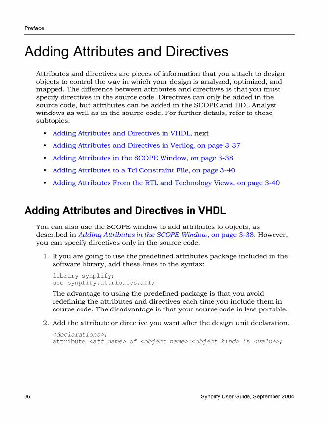
LO
Preface
36 Synplify User Guide, September 2004
Adding Attributes and DirectivesAttributes and directives are pieces of information that you attach to design objects to control the way in which your design is analyzed, optimized, and mapped. The difference between attributes and directives is that you must specify directives in the source code. Directives can only be added in the source code, but attributes can be added in the SCOPE and HDL Analyst windows as well as in the source code. For further details, refer to these subtopics:
• Adding Attributes and Directives in VHDL, next
• Adding Attributes and Directives in Verilog, on page 3-37
• Adding Attributes in the SCOPE Window, on page 3-38
• Adding Attributes to a Tcl Constraint File, on page 3-40
• Adding Attributes From the RTL and Technology Views, on page 3-40
Adding Attributes and Directives in VHDLYou can also use the SCOPE window to add attributes to objects, as described in Adding Attributes in the SCOPE Window, on page 3-38. However, you can specify directives only in the source code.
1. If you are going to use the predefined attributes package included in the software library, add these lines to the syntax:
library synplify;use synplify.attributes.all;
The advantage to using the predefined package is that you avoid redefining the attributes and directives each time you include them in source code. The disadvantage is that your source code is less portable.
2. Add the attribute or directive you want after the design unit declaration.
<declarations>;attribute <att_name> of <object_name>:<object_kind> is <value>;
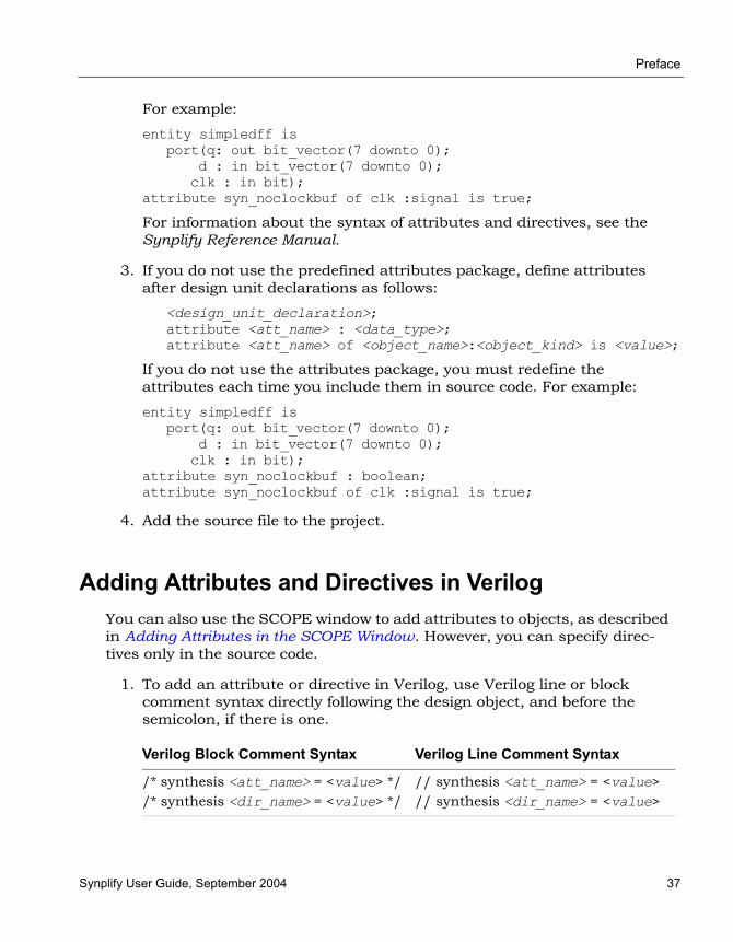
Preface
Synplify User Guide, September 2004 37
For example:
entity simpledff isport(q: out bit_vector(7 downto 0);
d : in bit_vector(7 downto 0);clk : in bit);
attribute syn_noclockbuf of clk :signal is true;
For information about the syntax of attributes and directives, see the Synplify Reference Manual.
3. If you do not use the predefined attributes package, define attributes after design unit declarations as follows:
<design_unit_declaration>;attribute <att_name> : <data_type>;attribute <att_name> of <object_name>:<object_kind> is <value>;
If you do not use the attributes package, you must redefine the attributes each time you include them in source code. For example:
entity simpledff isport(q: out bit_vector(7 downto 0);
d : in bit_vector(7 downto 0);clk : in bit);
attribute syn_noclockbuf : boolean;attribute syn_noclockbuf of clk :signal is true;
4. Add the source file to the project.
Adding Attributes and Directives in VerilogYou can also use the SCOPE window to add attributes to objects, as described in Adding Attributes in the SCOPE Window. However, you can specify direc-tives only in the source code.
1. To add an attribute or directive in Verilog, use Verilog line or block comment syntax directly following the design object, and before the semicolon, if there is one.
Verilog Block Comment Syntax Verilog Line Comment Syntax
/* synthesis <att_name> = <value> *//* synthesis <dir_name> = <value> */
// synthesis <att_name> = <value>// synthesis <dir_name> = <value>
LO
Preface
38 Synplify User Guide, September 2004
Verilog does not have predefined synthesis attributes and directives, so you must add them as comments. Note that the attribute or directive name is preceded by the keyword synthesis. For information about attributes and their values, refer to the Synplify Reference Manual.
The following are examples of attributes and directives:
module fifo(out, in) /* synthesis syn_hier = “firm“ */;
module b_box(out, in) /* synthesis syn_black_box */;
2. To attach multiple attributes or directives to the same object, separate the attributes with white spaces, but do not repeat the synthesis keyword. For example:
case state /* synthesis full_case parallel_case */;
Adding Attributes in the SCOPE WindowThe SCOPE window provides an easy-to-use interface to add any attribute. You cannot use it for adding directives, because they must be added to the source files. (See Adding Attributes and Directives in VHDL, on page 3-36 or Adding Attributes and Directives in Verilog, on page 3-37).
1. Start with a compiled design and open the SCOPE window. To add the attributes to an existing constraint file, open the SCOPE window by clicking on the existing file in the Project view. To add the attributes to a new file, click the SCOPE icon and click Initialize to open the SCOPE window.
2. Click the Attributes tab at the bottom of the SCOPE window.
You can either select the object first (step 2) or the attribute first (step 3).
3. To specify the object, do one of the following in the Object column. If you already specified the attribute, the Object column lists only valid object choices for that attribute.
– Drag the object to which you want to attach the attribute from the RTL or Technology views to the Object column in the SCOPE window.
– Select the type of object in the Object Filter column, and then select an object from the list of choices in the Object column.
– Type the name of the object in the Object column. If you do not know the name, use the Find command or the Object Filter column.

Preface
Synplify User Guide, September 2004 39
If you specified the object first, you can now specify the attribute. The list shows only the valid attributes for the type of object you selected.
4. Specify the attribute by holding down the mouse button in the Attribute column and selecting an attribute from the list.
If you selected the object first, the choices available are determined by the selected object and the technology you are using. If you selected the attribute first, the available choices are determined by the technology.
When you select an attribute, the SCOPE window tells you the kind of value you must enter for that attribute and provides a brief description of the attribute. If you selected the attribute first, make sure to go back and specify the object.
5. Fill out the value. Hold down the mouse button in the Value column, and select from the list. You can also type in a value.
If you manually type an attribute the software does not recognize, or select an incompatible attribute/object combination, the attribute cell is shaded in red.
6. Save the file and add it to the project, if it is not already in the project.
The software saves the SCOPE information in a Tcl constraint file, using the define_attribute syntax. See Adding Attributes to a Tcl Constraint File, on page 3-40 for information about adding this attribute manually to a constraint file. When you synthesize the design, the software reads the constraint file and applies the attribute.

LO
Preface
40 Synplify User Guide, September 2004
Adding Attributes to a Tcl Constraint FileWhen you add attributes through the SCOPE window (Adding Attributes in the SCOPE Window, on page 3-38), the attributes are automatically added to the constraint file using the Tcl define_attribute syntax. The following procedure explains how to add attributes manually to a Tcl constraint file. For informa-tion about editing the constraints in a constraint file, see Using a Text Editor for Constraint Files, on page 3-33.
1. In the constraint file, add the attribute and value you want, using the following define_attribute syntax.
define_attribute {object_name} attribute_name value
Check the descriptions of individual attributes in the Reference Manual for the exact values and syntax of the attribute.
Adding Attributes From the RTL and Technology ViewsYou can add attributes to instances, nets, or ports in the RTL or Technology windows.
1. If you already have a constraint file but you want to use a new one for the attributes, create a file first, and add it to the project. If you are using an existing constraint file, go to the next step.
2. Select an instance, net, or port in an RTL or Technology view.
You can only select a single object. The instance must be a primitive or a module.
3. Right-click and select SCOPE->Edit Attributes from the popup menu.
If the command is grayed out, you have selected an invalid object.
If you do not have a constraint file, the software asks you if you want to create one. If you select OK, the software automatically creates a constraint file and adds it to the project file. If you have a constraint file, the software opens and minimizes it. If there are multiple constraint files, you are prompted to choose one from a list.
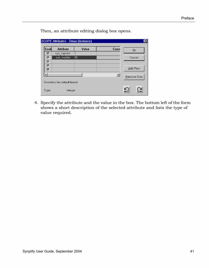
Preface
Synplify User Guide, September 2004 41
Then, an attribute editing dialog box opens.
4. Specify the attribute and the value in the box. The bottom left of the form shows a short description of the selected attribute and lists the type of value required.

LO
Preface
42 Synplify User Guide, September 2004

Synplify User Guide, September 2004 1
C H A P T E R 4
Result Analysis
This chapter describes typical analysis tasks. It describes graphical analysis with the HDL Analyst tool as well as interpretation of the text log file. It covers the following:
• Checking Log Results, on page 4-2
• Basic Operations in the Schematic Views, on page 4-10
• Exploring Design Hierarchy, on page 4-24
• Finding Objects, on page 4-30
• Crossprobing, on page 4-38
• Analyzing With the HDL Analyst Tool, on page 4-44
• Analyzing Timing, on page 4-61

LO
Preface
2 Synplify User Guide, September 2004
Checking Log ResultsYou can check the log file for information about the synthesis run. The following describe different ways to check the results of your run:
• Viewing the Log File, next
• Analyzing Results Using the Log File Reports, on page 4-4
• Handling Warnings, on page 4-4
Viewing the Log FileThe log file contains the most comprehensive results and information about a synthesis run.
1. To view the log file, select View -> Log File, or click the View Log button in the Project window. You see a Text Editor window with the log file.
The log file lists the compiled files, details of the synthesis run, color-coded errors, warnings and notes, and a number of reports. For infor-mation about the reports, see Analyzing Results Using the Log File Reports, on page 4-4.
For general information about working in an Editing window, including adding bookmarks, see Editing Source Files with the Built-in Text Editor, on page 2-5.
2. To find information in the log file, select Edit -> Find or press Ctrl-f. Fill out the criteria in the form and click OK.

Preface
Synplify User Guide, September 2004 3
The areas of the log file that are most important are the warning messages and the timing report. The following table lists places in the log file you can use when searching for information.
3. Resolve any errors and check all warnings.
You must fix errors, because you cannot synthesize a design with errors. Check the warnings and make sure you understand them. See Handling Warnings, on page 4-4 for information about some common warnings. Notes are usually informational, and can be ignored. For details about crossprobing and fixing errors, see Editing Source Files with the Built-in Text Editor, on page 2-5 .
4. If you are trying to find and resolve errors, you can bookmark them as shown in this procedure:
– Select Edit -> Find or press Ctrl-f.
– Type @W as the criteria on the Find form, and click Mark All. The software inserts bookmarks at every line with a warning. You can now page through the file from bookmark to bookmark using the commands in the Edit menu or the icons in the Edit toolbar. For more information on using bookmarks, see Editing Source Files with the Built-in Text Editor, on page 2-5.
5. To crossprobe from the log file to the source code, double-click on a warning.
To find... Search for...
Notes @N, or look for blue text
Warnings and errors @W and @E, or look for purple and red text respectively
Performance summary Performance Summary
The beginning of the timing report START TIMING REPORT
Detailed information about slack times, constraints, arrival times, etc.
Interface Information
Resource usage Resource Usage Report
Hierarchical usage Area Report

LO
Preface
4 Synplify User Guide, September 2004
Analyzing Results Using the Log File ReportsThe log file contains technology-appropriate reports like timing reports, resource usage reports and net buffering reports, in addition to any notes, errors, and warning messages.
1. To analyze timing results,
– View the Timing Report by going to the Performance Summary section of the log file.
– Check the slack times. See Handling Negative Slack, on page 4-65 for details.
– Check the detailed information for the critical paths, including the setup requirements at the end of the detailed critical path description. You can crossprobe and view the information graphically and determine how to improve the timing.
2. To check buffers,
– Check the report by going to the Net Buffering Report section of the log file.
– Check the number of buffers or registers added or replicated and determine whether this fits into your design optimization strategy.
3. To check logic resources,
– Go to the Resource Usage Report section at the end of the log file.
– Check the number and types of components used to determine if you have used too much of your resources.
Handling WarningsThe following cases describe some warning messages you might see in your log file and show how you can deal with them.
Asynchronous LoadsRegister <name> with async load is being synthesized in compatibility mode. A synthesis/simulation mismatch is possible.

Preface
Synplify User Guide, September 2004 5
This message is generated when the software creates objects that are not explicitly defined in the RTL code. For example, if you have a register with an asynchronous load, the software generates a set/reset register even if this is not defined in the code. To avoid simulation mismatches, rewrite the code with explicit assignments.
Verilog Example
Original Code Revised Code
always @(posedge clk or posedge load)beginif (load)q=d0;
else q=d1;
end
wire tmp_set = load & d0;wire tmp_rst = load & -d0;always @(posedge clk or posedgetm_rst or posedge tmp_set)
beginif (tmp_rst)q=0;
else if (tmp_set)q=1;
elseq=d;
end
VHDL Example
Original Code Revised Code
process (clk, load)beginif (load = '1') then )q <= d0;
elsif (rising_edge(clk)) thenq <=d;
end if;end
begintmp_set <= load and d0;tmp_rst <= load and not (d0);process (clk, tmp_rst, tmp_set)if (tmp_rst = '1') then )q <= 0;
elsif (t'p_set = '1') thenq <= '1’;
elsif (rising_edge(clk)) thenq <=d;
end if;end

LO
Preface
6 Synplify User Guide, September 2004
Latch InferenceLatch generated from always block for signal <name>, probably caused by a missing assignment in IF or CASE statement.
You see a message like this when you have not declared all the cases in a CASE or IF statement describing purely combinatorial logic. Even if this is permissible in your design, check to make sure. If you do not want to generate a latch, make sure to use a default clause or a Verilog full_case directive for CASE statements. Make sure you always use the else clause in IF-THEN-ELSE statements. If you require a latch, use assign statements.
The software generates a latch for the following example, because there is no assignment for sel2 = 11. To fix it, add a statement, as shown.
Latch generated because there is no assignment for case 11:
case sel2 iwhen "00" => mux41_out <= inp1;when "01" => mux41_out <= inp2;when "10" => mux41_out <= inp3;when others => null;end case;
No latch generated when all the cases are specified:
case sel2 iwhen "00" => mux41_out <= inp1;when "01" => mux41_out <= inp2;when "10" => mux41_out <= inp3;when "11" => mux41_out <= inp4;when others => null;end case;

Preface
Synplify User Guide, September 2004 7
Incomplete Sensitivity ListIncomplete Sensitivity List - assuming completeness. Referenced variable <name> is not in the sensitivity list.
The software generates this message if you have signals missing in the sensi-tivity list. The software assumes the list is complete and does not account for missing signals, so you could have a mismatch with the simulation results.
The following table shows pieces of code. In the examples on the left, the signal B is missing from the sensitivity list. When A is unchanged at 1, and B changes from 1 to 0, the code on the left is insensitive to the change and Y1 remains at 1 nand 1 or 0. However, when the code is written as shown on the right, it is sensitive to the change and the value is 1 nand 0 or 1.
Unused Inputs“<design>|Input <input name> is unused.
You see this kind of message when an input is unused. You must check these warnings because the software removes any logic that does not ultimately feed a primary output.
Verilog Example
Original Code Revised Code
module nand2(A,B,Y1);input A, B;output Y1;always @(A)beginY1 = !(A & B);
endendmodule
module nand2(A,B,Y1);input A, B;output Y1;always @(A or B)beginY1 = !(A & B);
endendmodule
VHDL Example
Original Code Revised Code
process (A)beginY1 <= A nand B;
end process;
process (A, B)beginY1 <= A nand B;
end process;
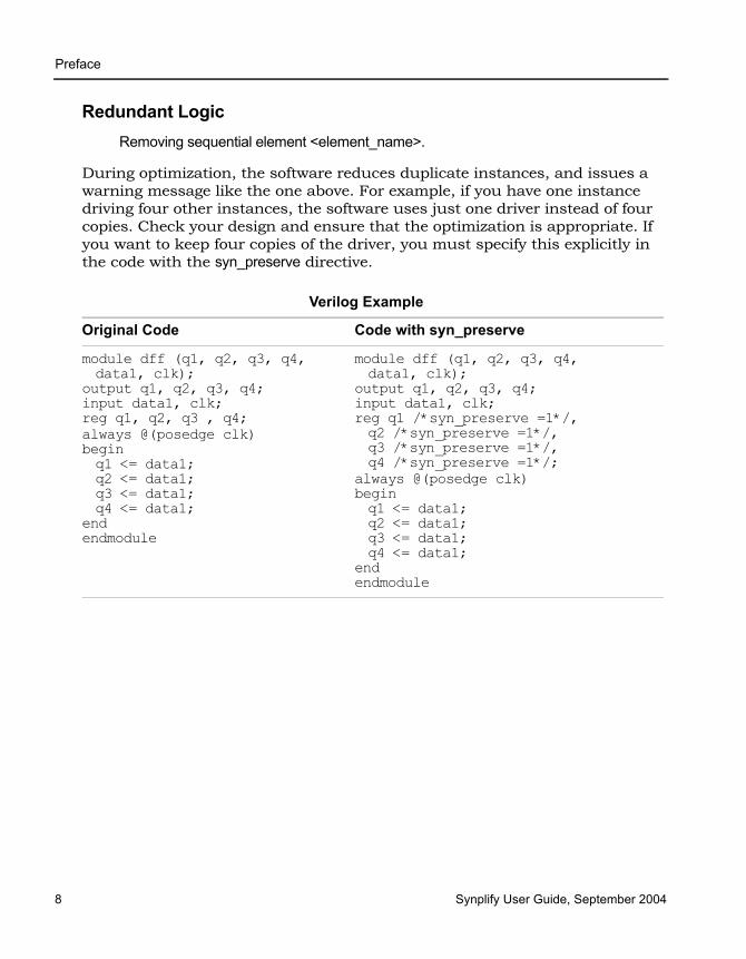
LO
Preface
8 Synplify User Guide, September 2004
Redundant LogicRemoving sequential element <element_name>.
During optimization, the software reduces duplicate instances, and issues a warning message like the one above. For example, if you have one instance driving four other instances, the software uses just one driver instead of four copies. Check your design and ensure that the optimization is appropriate. If you want to keep four copies of the driver, you must specify this explicitly in the code with the syn_preserve directive.
Verilog Example
Original Code Code with syn_preserve
module dff (q1, q2, q3, q4,data1, clk);
output q1, q2, q3, q4;input data1, clk;reg q1, q2, q3 , q4;always @(posedge clk)beginq1 <= data1;q2 <= data1;q3 <= data1;q4 <= data1;
endendmodule
module dff (q1, q2, q3, q4, data1, clk);
output q1, q2, q3, q4;input data1, clk;reg q1 /*syn_preserve =1*/, q2 /*syn_preserve =1*/, q3 /*syn_preserve =1*/, q4 /*syn_preserve =1*/;
always @(posedge clk)beginq1 <= data1;q2 <= data1;q3 <= data1;q4 <= data1;
endendmodule
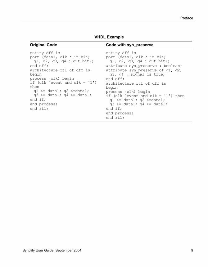
Preface
Synplify User Guide, September 2004 9
VHDL Example
Original Code Code with syn_preserve
entity dff isport (data1, clk : in bit;q1, q2, q3, q4 : out bit);
end dff;architecture rtl of dff is beginprocess (clk) beginif (clk ‘event and clk = '1') thenq1 <= data1; q2 <=data1; q3 <= data1; q4 <= data1;
end if;end process;end rtl;
entity dff isport (data1, clk : in bit;q1, q2, q3, q4 : out bit);
attribute syn_preserve : boolean;attribute syn_preserve of q1, q2,q3, q4 : signal is true;
end dff;architecture rtl of dff is beginprocess (clk) beginif (clk ‘event and clk = '1') thenq1 <= data1; q2 <=data1; q3 <= data1; q4 <= data1;
end if;end process;end rtl;

LO
Preface
10 Synplify User Guide, September 2004
Basic Operations in the Schematic ViewsThe RTL and Technology views are schematic views used to graphically analyze your design. They are part of the HDL Analyst package. The RTL view is available after a design is compiled; the Technology view is available after a designed has been synthesized and contains technology-specific primitives. For a detailed description of these views and operations, see Chapter 2 of the Synplify Reference Manual. This section describes basic procedures you use in the RTL and Technology views. The information is organized into these topics:
• Differentiating Between the Views, next
• Opening the Views, on page 4-11
• Analyzing Your Design Graphically, on page 4-13
• Viewing Object Properties, on page 4-14
• Selecting Objects in the RTL/Technology Views, on page 4-17
• Working with Multisheet Schematics, on page 4-18
• Moving Between Views in a Schematic Window, on page 4-20
• Setting Schematic View Preferences, on page 4-20
• Managing Windows, on page 4-22
For information on specific tasks like analyzing critical paths, see the following sections:
• Exploring Object Hierarchy by Pushing/Popping, on page 4-25
• Exploring Object Hierarchy of Transparent Instances, on page 4-29
• Browsing to Find Objects, on page 4-30
• Crossprobing, on page 4-38
• Analyzing With the HDL Analyst Tool, on page 4-44
• Analyzing Timing, on page 4-61
Preface
Synplify User Guide, September 2004 11
Differentiating Between the ViewsThe difference between the RTL and Technology views is that the RTL view is the view generated after compilation, while the Technology view is the view generated after mapping.
• The RTL view displays your design as a high-level, technology-indepen-dent schematic. At this high level of abstraction, the design is repre-sented with technology-independent components like variable-width adders, registers, large muxes, state machines, and so on. This view corresponds to the .srs netlist file generated by the software in the Synplicity proprietary format. For a detailed description, see Chapter 2 of the Synplify Reference Manual.
• The Technology view contains technology-specific primitives. It shows low-level vendor-specific components such as look-up tables, cascade and carry chains, muxes, and flip-flops, which can vary with the vendor and the technology. This view corresponds to the .srm netlist file, gener-ated by the software in the Synplicity proprietary format. For a detailed description, see Chapter 2 of the Synplify Reference Manual.
Opening the ViewsThe procedure for opening an RTL or Technology view is similar; the main difference is the design stage at which these views are available.
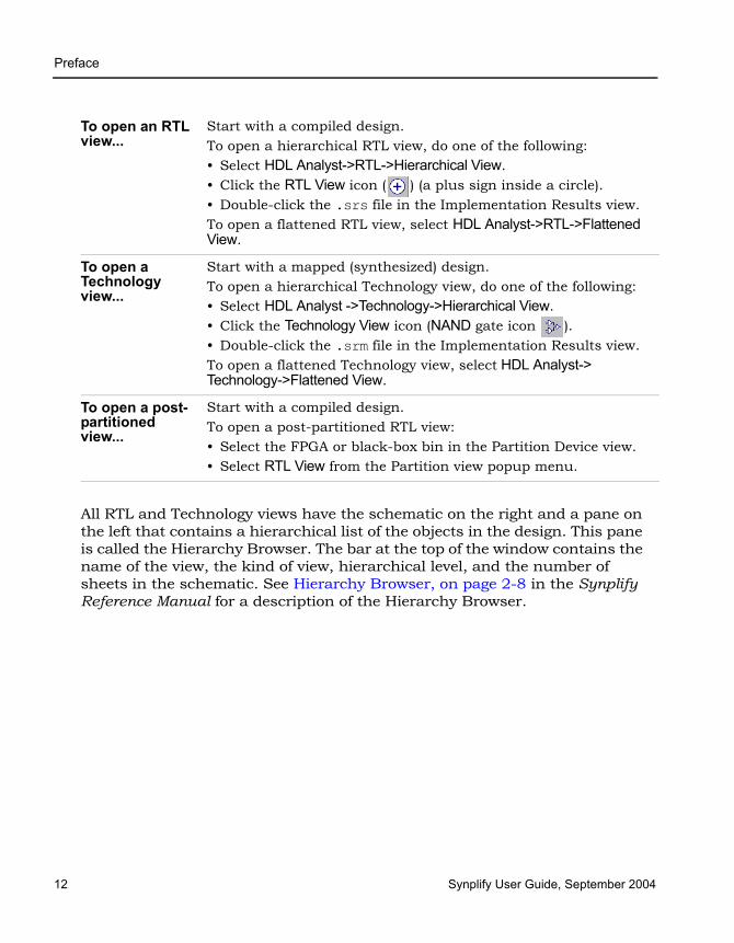
LO
Preface
12 Synplify User Guide, September 2004
All RTL and Technology views have the schematic on the right and a pane on the left that contains a hierarchical list of the objects in the design. This pane is called the Hierarchy Browser. The bar at the top of the window contains the name of the view, the kind of view, hierarchical level, and the number of sheets in the schematic. See Hierarchy Browser, on page 2-8 in the Synplify Reference Manual for a description of the Hierarchy Browser.
To open an RTL view...
Start with a compiled design. To open a hierarchical RTL view, do one of the following:• Select HDL Analyst->RTL->Hierarchical View. • Click the RTL View icon ( ) (a plus sign inside a circle).• Double-click the .srs file in the Implementation Results view.To open a flattened RTL view, select HDL Analyst->RTL->Flattened View.
To open a Technology view...
Start with a mapped (synthesized) design.To open a hierarchical Technology view, do one of the following: • Select HDL Analyst ->Technology->Hierarchical View. • Click the Technology View icon (NAND gate icon ). • Double-click the .srm file in the Implementation Results view.To open a flattened Technology view, select HDL Analyst-> Technology->Flattened View.
To open a post-partitioned view...
Start with a compiled design.To open a post-partitioned RTL view:• Select the FPGA or black-box bin in the Partition Device view.• Select RTL View from the Partition view popup menu.
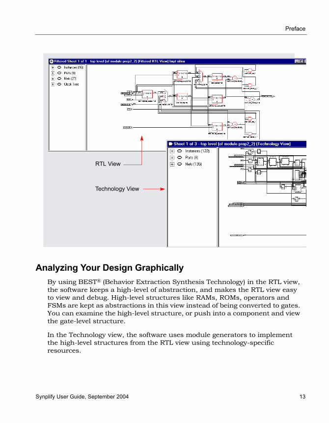
Preface
Synplify User Guide, September 2004 13
Analyzing Your Design GraphicallyBy using BEST® (Behavior Extraction Synthesis Technology) in the RTL view, the software keeps a high-level of abstraction, and makes the RTL view easy to view and debug. High-level structures like RAMs, ROMs, operators and FSMs are kept as abstractions in this view instead of being converted to gates. You can examine the high-level structure, or push into a component and view the gate-level structure.
In the Technology view, the software uses module generators to implement the high-level structures from the RTL view using technology-specific resources.
Technology View
RTL View

LO
Preface
14 Synplify User Guide, September 2004
To analyze information, compare the current view with the information in the RTL/Technology view, the log file, and the source code. You can use techniques like crossprobing, flattening, and filtering to isolate and examine the components. The following table points you to where you can find more information about some analysis techniques.
Viewing Object PropertiesThere are a few ways in which you can view the properties of objects.
1. To temporarily display the properties of a particular object, hold the cursor over the object. A tooltip temporarily displays the information. at the cursor and in the status bar at the bottom of the product window.
2. Select the object, right-click and select Properties. The properties and their values are displayed in a table.
If you select an instance, you can view the properties of the associated pins by selecting the pin from the list . Similarly, if you select a port, you can view the properties on individual bits.
For Information About See...
Crossprobing Crossprobing, on page 4-38
Analyzing logic Analyzing With the HDL Analyst Tool, on page 4-44
Isolating or filtering logic Filtering Schematics, on page 4-48
Expanding filtered logic Expanding Pin and Net Logic, on page 4-50 and Expanding and Viewing Connections, on page 4-54
Flattening Flattening Schematic Hierarchy, on page 4-56
Analyzing timing Analyzing Timing, on page 4-61

Preface
Synplify User Guide, September 2004 15
3. To flag objects by property, do the following with an open RTL/Technology view:
– Set the properties you want to see by selecting Options->Schematic Options->Visual Properties, and selecting the properties from the pulldown list. Some properties are only available in certain views.
– Close the Schematic Options dialog box.
Set this field to the pin name to see pin properties
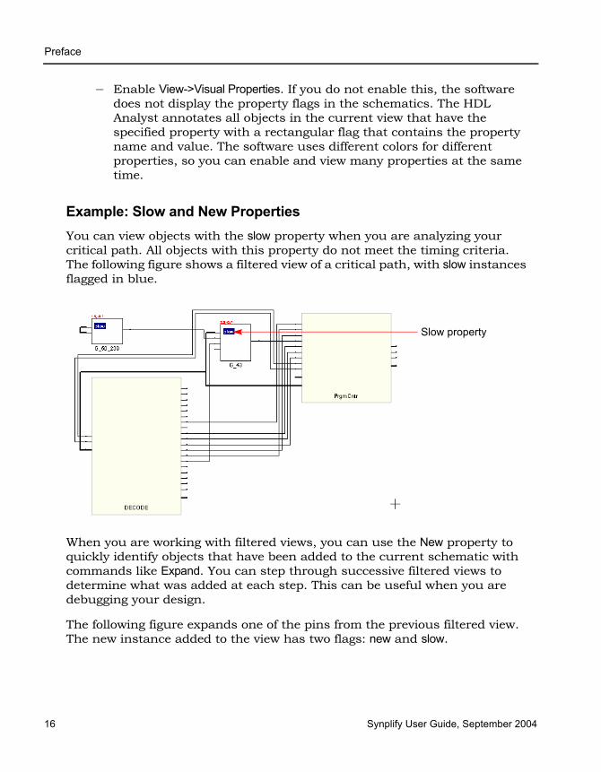
LO
Preface
16 Synplify User Guide, September 2004
– Enable View->Visual Properties. If you do not enable this, the software does not display the property flags in the schematics. The HDL Analyst annotates all objects in the current view that have the specified property with a rectangular flag that contains the property name and value. The software uses different colors for different properties, so you can enable and view many properties at the same time.
Example: Slow and New PropertiesYou can view objects with the slow property when you are analyzing your critical path. All objects with this property do not meet the timing criteria. The following figure shows a filtered view of a critical path, with slow instances flagged in blue.
When you are working with filtered views, you can use the New property to quickly identify objects that have been added to the current schematic with commands like Expand. You can step through successive filtered views to determine what was added at each step. This can be useful when you are debugging your design.
The following figure expands one of the pins from the previous filtered view. The new instance added to the view has two flags: new and slow.
Slow property
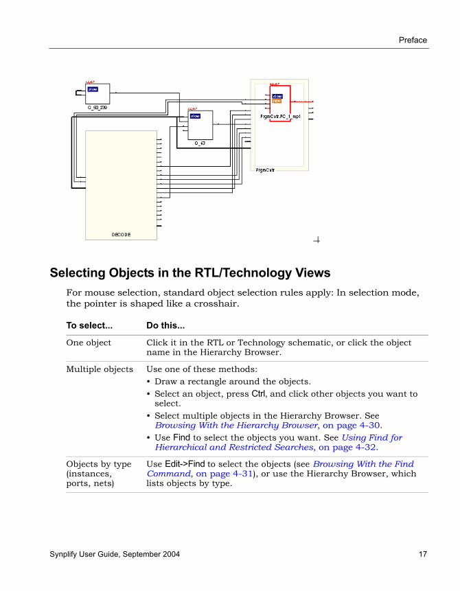
Preface
Synplify User Guide, September 2004 17
Selecting Objects in the RTL/Technology ViewsFor mouse selection, standard object selection rules apply: In selection mode, the pointer is shaped like a crosshair.
To select... Do this...
One object Click it in the RTL or Technology schematic, or click the object name in the Hierarchy Browser.
Multiple objects Use one of these methods:• Draw a rectangle around the objects. • Select an object, press Ctrl, and click other objects you want to
select.• Select multiple objects in the Hierarchy Browser. See
Browsing With the Hierarchy Browser, on page 4-30. • Use Find to select the objects you want. See Using Find for
Hierarchical and Restricted Searches, on page 4-32.
Objects by type (instances, ports, nets)
Use Edit->Find to select the objects (see Browsing With the Find Command, on page 4-31), or use the Hierarchy Browser, which lists objects by type.
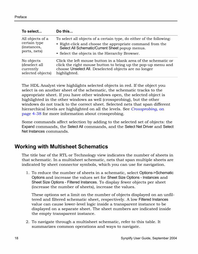
LO
Preface
18 Synplify User Guide, September 2004
The HDL Analyst view highlights selected objects in red. If the object you select is on another sheet of the schematic, the schematic tracks to the appropriate sheet. If you have other windows open, the selected object is highlighted in the other windows as well (crossprobing), but the other windows do not track to the correct sheet. Selected nets that span different hierarchical levels are highlighted on all the levels. See Crossprobing, on page 4-38 for more information about crossprobing.
Some commands affect selection by adding to the selected set of objects: the Expand commands, the Select All commands, and the Select Net Driver and Select Net Instances commands.
Working with Multisheet SchematicsThe title bar of the RTL or Technology view indicates the number of sheets in that schematic. In a multisheet schematic, nets that span multiple sheets are indicated by sheet connector symbols, which you can use for navigation.
1. To reduce the number of sheets in a schematic, select Options->Schematic Options and increase the values set for Sheet Size Options - Instances and Sheet Size Options - Filtered Instances. To display fewer objects per sheet (increase the number of sheets), increase the values.
These options set a limit on the number of objects displayed on an unfil-tered and filtered schematic sheet, respectively. A low Filtered Instances value can cause lower-level logic inside a transparent instance to be displayed on a separate sheet. The sheet numbers are indicated inside the empty transparent instance.
2. To navigate through a multisheet schematic, refer to this table. It summarizes common operations and ways to navigate.
All objects of a certain type (instances, ports, nets)
To select all objects of a certain type, do either of the following:• Right-click and choose the appropriate command from the
Select All Schematic/Current Sheet popup menus. • Select the objects in the Hierarchy Browser.
No objects (deselect all currently selected objects)
Click the left mouse button in a blank area of the schematic or click the right mouse button to bring up the pop-up menu and choose Unselect All. Deselected objects are no longer highlighted.
To select... Do this...
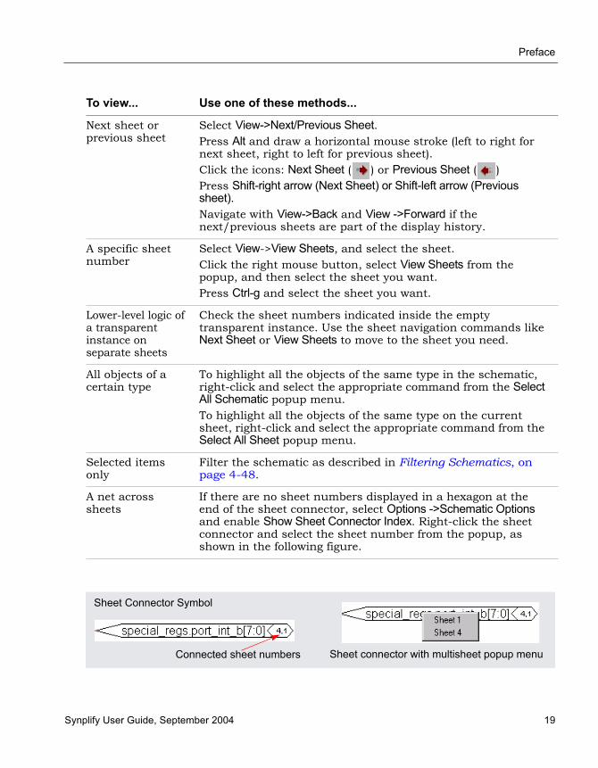
Preface
Synplify User Guide, September 2004 19
To view... Use one of these methods...
Next sheet or previous sheet
Select View->Next/Previous Sheet. Press Alt and draw a horizontal mouse stroke (left to right for next sheet, right to left for previous sheet).Click the icons: Next Sheet ( ) or Previous Sheet ( ) Press Shift-right arrow (Next Sheet) or Shift-left arrow (Previous sheet).Navigate with View->Back and View ->Forward if the next/previous sheets are part of the display history.
A specific sheet number
Select View->View Sheets, and select the sheet. Click the right mouse button, select View Sheets from the popup, and then select the sheet you want. Press Ctrl-g and select the sheet you want.
Lower-level logic of a transparent instance on separate sheets
Check the sheet numbers indicated inside the empty transparent instance. Use the sheet navigation commands like Next Sheet or View Sheets to move to the sheet you need.
All objects of a certain type
To highlight all the objects of the same type in the schematic, right-click and select the appropriate command from the Select All Schematic popup menu. To highlight all the objects of the same type on the current sheet, right-click and select the appropriate command from the Select All Sheet popup menu.
Selected items only
Filter the schematic as described in Filtering Schematics, on page 4-48.
A net across sheets
If there are no sheet numbers displayed in a hexagon at the end of the sheet connector, select Options ->Schematic Options and enable Show Sheet Connector Index. Right-click the sheet connector and select the sheet number from the popup, as shown in the following figure.
Sheet Connector Symbol
Sheet connector with multisheet popup menuConnected sheet numbers
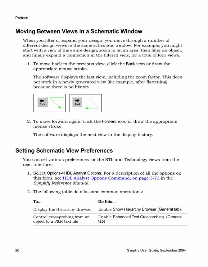
LO
Preface
20 Synplify User Guide, September 2004
Moving Between Views in a Schematic WindowWhen you filter or expand your design, you move through a number of different design views in the same schematic window. For example, you might start with a view of the entire design, zoom in on an area, then filter an object, and finally expand a connection in the filtered view, for a total of four views.
1. To move back to the previous view, click the Back icon or draw the appropriate mouse stroke.
The software displays the last view, including the zoom factor. This does not work in a newly generated view (for example, after flattening) because there is no history.
2. To move forward again, click the Forward icon or draw the appropriate mouse stroke.
The software displays the next view in the display history.
Setting Schematic View PreferencesYou can set various preferences for the RTL and Technology views from the user interface.
1. Select Options->HDL Analyst Options. For a description of all the options on this form, see HDL Analyst Options Command, on page 3-73 in the Synplify Reference Manual.
2. The following table details some common operations:
To... Do this...
Display the Hierarchy Browser Enable Show Hierarchy Browser (General tab).
Control crossprobing from an object to a P&R text file
Enable Enhanced Text Crossprobing. (General tab)

Preface
Synplify User Guide, September 2004 21
Some of these options do not take effect in the current view, but are visible in the next schematic view you open.
3. To view hierarchy within a cell, enable the General -> Show Cell Interiors option.
4. To control the display of labels, first enable the Text->Show Text option, and then enable the Label Options you want. The following figure illustrates the label that each option controls.
Determine the number of objects displayed on a sheet.
Set the value with Maximum Instances on the Sheet Size tab. Increase the value to display more objects per sheet.
Determine the number of objects displayed on a sheet in a filtered view.
Set the value with Maximum Filtered Instances on the Sheet Size tab. Increase the number to display more objects per sheet. You cannot set this option to a value less than the Maximum Instances value.
To... Do this...
Show Cell Interior off Show Cell Interior on

LO
Preface
22 Synplify User Guide, September 2004
For a more detailed information about some of these options, see Schematic Display, on page 6-9 in the Synplify Reference Manual.
5. Click OK on the Schematic Options form.
The software writes the preferences you set to the .ini file, and they remain in effect until you change them.
Managing WindowsAs you work on a project, you open different windows. For example, you might have two Technology views, an RTL view, and a source code window open. The following guidelines help you manage the different windows you have open. For information about cycling through the display history in a single schematic, see Moving Between Views in a Schematic Window, on page 4-20.
1. Toggle on View->Workbook Mode.
Below the Project view, you see tabs like the following for each open view. The tab for the current view is on top. The symbols in front of the view name on the tab help identify the kind of view.
Show Instance Name
Show Symbol Name
Show Pin NameShow Conn Name
Show Port Name

Preface
Synplify User Guide, September 2004 23
2. To bring an open view to the front, do one of the following:
– If the window is not visible, click its tab. If part of the window is visible, click in any part of the window.
– If you previously minimized the view, it will be in minimized form. Double-click the minimized view to open it.
3. To bring the next view to the front, click Ctrl-F6 in that window.
4. Order the display of open views with the commands from the Window menu. You can cascade the views (stack them, slightly offset), or tile them horizontally or vertically.
5. To close a view, press Ctrl-F4 in that window or select File->Close.
LO
Preface
24 Synplify User Guide, September 2004
Exploring Design HierarchySchematics generally have a certain amount of design hierarchy. You can move between hierarchical levels using the Hierarchy Browser or Push/Pop mode. For additional information, see Analyzing With the HDL Analyst Tool, on page 4-44.
Traversing Design Hierarchy with the Hierarchy BrowserThe Hierarchy Browser is the list of objects on the left side of the RTL and Technology views. It is best used to get an overview, or when you need to browse and find an object. If you want to move between design levels of a particular object, Push/Pop mode is more direct. Refer to Exploring Object Hierarchy by Pushing/Popping, on page 4-25 for details.
The hierarchy browser allows you to traverse and select the following:
• Instances and submodules
• Ports
• Internal nets
• Clock trees (in an RTL view)
The browser lists the objects by type. A plus sign in a square icon indicates that there is hierarchy under that object, and a minus sign indicates that the design hierarchy has been expanded. To see lower-level hierarchy, click on the plus sign for the object. To ascend the hierarchy, click on the minus sign.
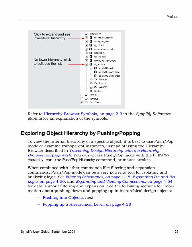
Preface
Synplify User Guide, September 2004 25
Refer to Hierarchy Browser Symbols, on page 2-9 in the Synplify Reference Manual for an explanation of the symbols.
Exploring Object Hierarchy by Pushing/PoppingTo view the internal hierarchy of a specific object, it is best to use Push/Pop mode or examine transparent instances, instead of using the Hierarchy Browser described in Traversing Design Hierarchy with the Hierarchy Browser, on page 4-24. You can access Push/Pop mode with the Push/Pop Hierarchy icon, the Push/Pop Hierarchy command, or mouse strokes.
When combined with other commands like filtering and expansion commands, Push/Pop mode can be a very powerful tool for isolating and analyzing logic. See Filtering Schematics, on page 4-48, Expanding Pin and Net Logic, on page 4-50, and Expanding and Viewing Connections, on page 4-54 for details about filtering and expansion. See the following sections for infor-mation about pushing down and popping up in hierarchical design objects:
– Pushing into Objects, next
– Popping up a Hierarchical Level, on page 4-28
No lower hierarchy; click to collapse the list.
Click to expand and see lower-level hierarchy
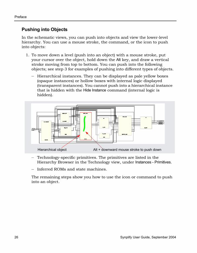
LO
Preface
26 Synplify User Guide, September 2004
Pushing into ObjectsIn the schematic views, you can push into objects and view the lower-level hierarchy. You can use a mouse stroke, the command, or the icon to push into objects:
1. To move down a level (push into an object) with a mouse stroke, put your cursor over the object, hold down the Alt key, and draw a vertical stroke moving from top to bottom. You can push into the following objects; see step 3 for examples of pushing into different types of objects.
– Hierarchical instances. They can be displayed as pale yellow boxes (opaque instances) or hollow boxes with internal logic displayed (transparent instances). You cannot push into a hierarchical instance that is hidden with the Hide Instance command (internal logic is hidden).
– Technology-specific primitives. The primitives are listed in the Hierarchy Browser in the Technology view, under Instances - Primitives.
– Inferred ROMs and state machines.
The remaining steps show you how to use the icon or command to push into an object.
Hierarchical object Alt + downward mouse stroke to push down
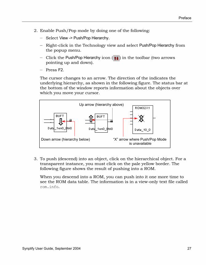
Preface
Synplify User Guide, September 2004 27
2. Enable Push/Pop mode by doing one of the following:
– Select View -> Push/Pop Hierarchy.
– Right-click in the Technology view and select Push/Pop Hierarchy from the popup menu.
– Click the Push/Pop Hierarchy icon ( ) in the toolbar (two arrows pointing up and down).
– Press F2.
The cursor changes to an arrow. The direction of the indicates the underlying hierarchy, as shown in the following figure. The status bar at the bottom of the window reports information about the objects over which you move your cursor.
3. To push (descend) into an object, click on the hierarchical object. For a transparent instance, you must click on the pale yellow border. The following figure shows the result of pushing into a ROM.
When you descend into a ROM, you can push into it one more time to see the ROM data table. The information is in a view-only text file called rom.info.
“X” arrow where Push/Pop Mode
Up arrow (hierarchy above)
Down arrow (hierarchy below)is unavailable

LO
Preface
28 Synplify User Guide, September 2004
Popping up a Hierarchical Level1. To move up a level (pop up a level), put your cursor anywhere in the
design, hold down the Alt key, and draw a vertical mouse stroke, moving from the bottom upwards.
The software moves up a level, and displays the next level of hierarchy.
Alt + upward mouse stroke to pop up a level

Preface
Synplify User Guide, September 2004 29
2. To pop (ascend) a level using the commands or icon, do the following:
– Select the command or icon if you are not already in Push/Pop mode. See Pushing into Objects, on page 4-26for details.
– Move your cursor to a blank area and click.
3. To exit Push/Pop mode, do one of the following:
– Click the right mouse button in a blank area of the view.
– Deselect View->Push/Pop Hierarchy.
– Deselect the Push/Pop Hierarchy icon.
– Press F2.
Exploring Object Hierarchy of Transparent InstancesExamining a transparent instance is one way of exploring the design hierarchy of an object. The following table compares this method with pushing (described in Exploring Object Hierarchy by Pushing/Popping, on page 4-25).
Pushing Transparent Instance
User control
You initiate the operation through the command or icon.
You have no direct control; the transparent instance is automatically generated by some commands that result in a filtered view.
Design context
Context lost; the lower-level logic is shown in a separate view
Context maintained; lower-level logic is displayed inside a hollow yellow box at the hierarchical level of the parent.

LO
Preface
30 Synplify User Guide, September 2004
Finding ObjectsYou can use the Hierarchy Browser or the Find command to find objects., as explained in these sections:
• Browsing to Find Objects, next
• Using Find for Hierarchical and Restricted Searches, on page 4-32
• Using Wildcards with the Find Command, on page 4-35
Browsing to Find ObjectsYou can always zoom in to find an object in the RTL and Technology schematics. The following procedure shows you how to browse through design objects and find an object at any level of the design hierarchy. You can use the Hierarchy Browser or the Find command to do this. If you are familiar with the design hierarchy, the Hierarchy Browser can be the quickest method to locate an object. The Find command is best used to graphically browse and locate the object you want.
Browsing With the Hierarchy Browser1. In the Hierarchy Browser, click the name of the net, port, or instance
you want to select.
The object is highlighted in the schematic.
2. To select a range of objects, select the first object in the range. Then, scroll to to display the last object in the range. Press and hold the Shift key while clicking the last object in the range.
The software selects and highlights all the objects in the range.
3. If the object is on a lower hierarchical level, do either of the following:
– Expand the appropriate higher-level object by clicking the plus symbol next to it, and then select the object you want.
– Push down into the higher-level object, and then select the object from the Hierarchy Browser.
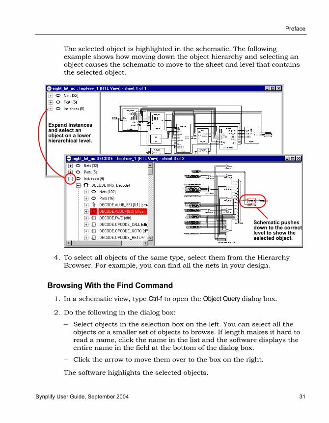
Preface
Synplify User Guide, September 2004 31
The selected object is highlighted in the schematic. The following example shows how moving down the object hierarchy and selecting an object causes the schematic to move to the sheet and level that contains the selected object.
4. To select all objects of the same type, select them from the Hierarchy Browser. For example, you can find all the nets in your design.
Browsing With the Find Command1. In a schematic view, type Ctrl-f to open the Object Query dialog box.
2. Do the following in the dialog box:
– Select objects in the selection box on the left. You can select all the objects or a smaller set of objects to browse. If length makes it hard to read a name, click the name in the list and the software displays the entire name in the field at the bottom of the dialog box.
– Click the arrow to move them over to the box on the right.
The software highlights the selected objects.
Expand Instances and select an object on a lower hierarchical level.
Schematic pushes down to the correct level to show the selected object.

LO
Preface
32 Synplify User Guide, September 2004
3. In the Object Query dialog box, click on an object in the box on the right.
The software tracks to the schematic page with that object.
Using Find for Hierarchical and Restricted SearchesYou can always zoom in to find an object in the RTL and Technology schematics or use the Hierarchy Browser (see Browsing to Find Objects, on page 4-30). This procedure shows you how to use the Find command to do hierarchical object searches or restrict the search to the current level or the current level and its underlying hierarchy.
1. If needed, restrict the range of the search by filtering the view, hiding instances, or both.
See Viewing Design Hierarchy and Context, on page 4-44 and Filtering Schematics, on page 4-48 for details. With a filtered view, the software only searches the filtered instances, unless you set the scope of the search to Entire Design, as described below. In that case, Find searches the entire design. Hidden instances and their hierarchy are excluded from the search. When you have finished the search, use the Unhide Instances command to make the hierarchy visible.
You can use the filtering technique to restrict your search to just one schematic sheet. Select all the objects on one sheet and filter the view. Continue with the procedure
2. Select HDL Analyst->Find or press Control-f, to open the Object Query form. Move the dialog box so you can see both your schematic and the dialog box.

Preface
Synplify User Guide, September 2004 33
3. Select the tab (at the top of the form) for the type of object. The Unhighlighted box on the left lists all objects of that type.
For fastest results, search by Instances rather than Nets. When you select Nets, the software loads the whole design, which could take some time.
4. Click one of these buttons to set the hierarchical range for the search: Entire Design, Current Level & Below, or Current Level Only, depending on the hierarchical level of the design to which you want to restrict your search.
The range setting is especially important when you use wildcards. See Effect of Search Range on Wildcard Searches, on page 4-35 for details. Current Level Only or Current Level & Below are useful for searching filtered schematics or critical path schematics.
Use Entire Design to hierarchically search the whole design. For large hierarchical designs, reduce the scope of the search by using the techniques described in the first step.
The Unhighlighted box shows available objects within the scope you set. Objects are listed in alphabetical order, not hierarchical order.
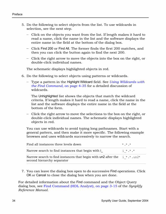
LO
Preface
34 Synplify User Guide, September 2004
5. Do the following to select objects from the list. To use wildcards in selection, see the next step.
– Click on the objects you want from the list. If length makes it hard to read a name, click the name in the list and the software displays the entire name in the field at the bottom of the dialog box.
– Click Find 200 or Find All. The former finds the first 200 matches, and then you can click the button again to find the next 200.
– Click the right arrow to move the objects into the box on the right, or double-click individual names.
The schematic displays highlighted objects in red.
6. Do the following to select objects using patterns or wildcards.
– Type a pattern in the Highlight Wildcard field. See Using Wildcards with the Find Command, on page 4-35 for a detailed discussion of wildcards.
The Unhighlighted list shows the objects that match the wildcard criteria. If length makes it hard to read a name, click the name in the list and the software displays the entire name in the field at the bottom of the form.
– Click the right arrow to move the selections to the box on the right, or double-click individual names. The schematic displays highlighted objects in red.
You can use wildcards to avoid typing long pathnames. Start with a general pattern, and then make it more specific. The following example browses and uses wildcards successively to narrow the search.
7. You can leave the dialog box open to do successive Find operations. Click OK or Cancel to close the dialog box when you are done.
For detailed information about the Find command and the Object Query dialog box, see Find Command (HDL Analyst), on page 3-15 of the Synplify Reference Manual.
Find all instances three levels down *.*.*
Narrow search to find instances that begin with i_ i_*.*.*
Narrow search to find instances that begin with un2 after the second hierarchy separator
i_*.*.un2*
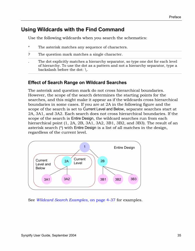
Preface
Synplify User Guide, September 2004 35
Using Wildcards with the Find CommandUse the following wildcards when you search the schematics:
Effect of Search Range on Wildcard SearchesThe asterisk and question mark do not cross hierarchical boundaries. However, the scope of the search determines the starting points for the searches, and this might make it appear as if the wildcards cross hierarchical boundaries in some cases. If you are at 2A in the following figure and the scope of the search is set to Current Level and Below, separate searches start at 2A, 3A1, and 3A2. Each search does not cross hierarchical boundaries. If the scope of the search is Entire Design, the wildcard searches run from each hierarchical point (1, 2A, 2B, 3A1, 3A2, 3B1, 3B2, and 3B3). The result of an asterisk search (*) with Entire Design is a list of all matches in the design, regardless of the current level.
See Wildcard Search Examples, on page 4-37 for examples.
* The asterisk matches any sequence of characters.
? The question mark matches a single character.
. The dot explicitly matches a hierarchy separator, so type one dot for each level of hierarchy. To use the dot as a pattern and not a hierarchy separator, type a backslash before the dot: \.
2A
1
2B
3B33B23B13A23A1
Entire Design
Current Level and Below
Current Level
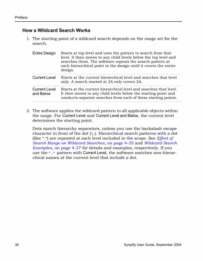
LO
Preface
36 Synplify User Guide, September 2004
How a Wildcard Search Works1. The starting point of a wildcard search depends on the range set for the
search.
2. The software applies the wildcard pattern to all applicable objects within the range. For Current Level and Current Level and Below, the current level determines the starting point.
Dots match hierarchy separators, unless you use the backslash escape character in front of the dot (\.). Hierarchical search patterns with a dot (like *.*) are repeated at each level included in the scope. See Effect of Search Range on Wildcard Searches, on page 4-35 and Wildcard Search Examples, on page 4-37 for details and examples, respectively. If you use the *.* pattern with Current Level, the software matches non-hierar-chical names at the current level that include a dot.
Entire Design Starts at top level and uses the pattern to search from that level. It then moves to any child levels below the top level and searches them. The software repeats the search pattern at each hierarchical point in the design until it covers the entire design.
Current Level Starts at the current hierarchical level and searches that level only. A search started at 2A only covers 2A.
Current Level and Below
Starts at the current hierarchical level and searches that level. It then moves to any child levels below the starting point and conducts separate searches from each of these starting points.
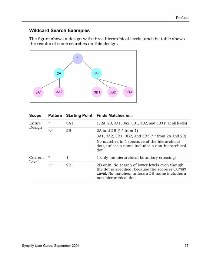
Preface
Synplify User Guide, September 2004 37
Wildcard Search ExamplesThe figure shows a design with three hierarchical levels, and the table shows the results of some searches on this design.
Scope Pattern Starting Point Finds Matches in...
Entire Design
* 3A1 1, 2A, 2B, 3A1, 3A2, 3B1, 3B2, and 3B3 (* at all levels)
*.* 2B 2A and 2B (*.* from 1)3A1, 3A2, 3B1, 3B2, and 3B3 (*.* from 2A and 2B)No matches in 1 (because of the hierarchical dot), unless a name includes a non-hierarchical dot.
Current Level
* 1 1 only (no hierarchical boundary crossing)
*.* 2B 2B only. No search of lower levels even though the dot is specified, because the scope is Current Level. No matches, unless a 2B name includes a non-hierarchical dot.
2A
1
2B
3B33B23B13A23A1

LO
Preface
38 Synplify User Guide, September 2004
Crossprobing This section describes how to crossprobe from different views. It includes the following:
• Crossprobing Description, on page 4-38, next
• Crossprobing within an RTL/Technology View, on page 4-39
• Crossprobing from the RTL/Technology View, on page 4-40
• Crossprobing from the Text Editor Window, on page 4-42
Crossprobing DescriptionCrossprobing is the process of selecting an object in one view and having the object or the corresponding logic automatically highlighted in other views. Highlighting a line of text, for example, highlights the corresponding logic in the schematic views. Crossprobing helps you visualize where coding changes or timing constraints might help to reduce area or increase performance.
You can crossprobe between the RTL view, Technology view, the log file, the source files, and some external text files from place-and-route tools. However, not all objects or source code crossprobe to other views, because some source code and RTL view logic is optimized away during the compilation or mapping processes.
Current Level and Below
* 2A 2A only (no hierarchical boundary crossing)
*.* 1 2A and 2B (*.* from 1)3A1, 3A2, 3B1, 3B2, and 3B3 (*.* from 2A and 2B)No matches from 1, because the dot is specified.
*.* 2B 3B1, 3B2, and 3B3 (*.* from 2B)
*.* 3A2 No matches (no hierarchy below 3A2)
*.*.* 1 3A1, 3A2, 3B1, 3B2, and 3B3 (*.*.* from 1)Search ends because there is no hierarchy two levels below 2A and 2B.
Scope Pattern Starting Point Finds Matches in...

Preface
Synplify User Guide, September 2004 39
For further details, see Crossprobing, on page 4-38 of the Synplify Reference Manual.
Crossprobing within an RTL/Technology ViewSelecting an object name in the Hierarchy Browser highlights the object in the schematic, and vice versa.
In this example, when you select the DECODE module in the Hierarchy Browser, the DECODE module is automatically selected in the RTL view.
Selected Object Highlighted Object
Instance in schematic (single-click) Module icon in Hierarchy Browser
Net in schematic Net icon in Hierarchy Browser
Port in schematic Port icon in Hierarchy Browser
Logic icon in Hierarchy Browser Instance in schematic
Net icon in Hierarchy Browser Net in schematic
Port icon in Hierarchy Browser Port in schematic

LO
Preface
40 Synplify User Guide, September 2004
Crossprobing from the RTL/Technology View1. To crossprobe from an RTL or Technology views to other open views,
select the object by clicking on it.
The software automatically highlights the object in all open views. If the open view is a schematic, the software highlights the object in the Hierarchy Browser on the left as well as in the schematic. If the highlighted object is on another sheet of a multi-sheet schematic, the view does not automatically track to the page. If the crossprobed object is inside a hidden instance, the hidden instance is highlighted in the schematic.
If the open view is a source file, the software tracks to the appropriate code and highlights it. The following figure shows crossprobing between the RTL, Technology, and Text Editor (source code) views.

Preface
Synplify User Guide, September 2004 41
2. To crossprobe from the RTL or Technology view to the source file when the source file is not open, double-click on the object in the RTL or Technology view.
Double-clicking automatically opens the appropriate source code file, and highlights the appropriate code. For example, if you double-click an object in a Technology view, the HDL Analyst tool automatically opens an editor window with the source code and highlights the code that contains the selected register.
The following table summarizes the crossprobing capability from the RTL or Technology view.
3. To crossprobe and trace component cause with Visual Elite software, select HDL Analyst->Connect to Visual Elite and click the object in the HDL Analyst view. See Working with Visual Elite, on page 7-12 for details of the setup and procedure.
4. To crossprobe simulation waveforms from ModelSim, follow the procedure described in Integrating with ModelSim, on page 7-10.
From To Procedure
RTL Source code Double-click an object. If the source code file is not open, the software opens the Text Editor window to the appropriate piece of code. If the source file is already open, the software scrolls to the correct section of the code and highlights it.
RTL Technology The Technology view must be open. Click the object to highlight and crossprobe.
Technology Source code If the source code file is already, open, the software scrolls to the correct section of the code and highlights it. If the source code file is not open, double-click an object in the Technology view to open the source code file.
Technology RTL The RTL view must be open. Click the object to highlight and crossprobe.
LO
Preface
42 Synplify User Guide, September 2004
Crossprobing from the Text Editor WindowTo crossprobe from a source code window or the log file to an RTL, Technology view, use this procedure. You can use this method to crossprobe from any text file with objects that have the same instance names as in the synthesis software. For example, you can crossprobe from place-and-route files. See Example of Crossprobing a Path from a Text File, on page 4-42 for a practical example of how to use crossprobing.
1. Open the RTL or Technology view to which you want to crossprobe.
2. To crossprobe from a log file, double-click the note, warning, or error to open the corresponding source code in another Text Editor window.
3. To crossprobe from a third-party text file (not source code or a log file), select Options->Schematic Options-General, and enable Enhanced Text Crossprobing.
4. Select the appropriate portion of text in the Text Editor window. In some cases, you might have to select the entire block of text to crossprobe.
The software highlights the objects corresponding to the selected code in all the open windows. If an object is on another schematic sheet or on another hierarchical level, the highlighting might not be obvious. If you filter the RTL or schematic view (right-click in the source code window with the selected text and select Filter Schematic from the popup menu), you can isolate the highlighted objects for easy viewing.
Example of Crossprobing a Path from a Text FileThis example selects a path in a log file and crossprobes it in the Technology view. You can use the same technique to crossprobe from other text files like place-and-route files, as long as the instance names in the text file match the instance names in the synthesis tool.
1. Open the log file, the RTL, and Technology views.
2. Select the path objects in the log file.
– Select the column by pressing Alt and dragging the cursor to the end of the column. On UNIX and Linux platforms, use the key to which the Alt function is mapped; this is usually the Meta or Diamond key for UNIX or the Ctrl-Alt key combination for Linux.

Preface
Synplify User Guide, September 2004 43
– To select all the objects in the path, right-click and choose Select All from the popup menu. Alternatively, you can select certain objects only, as described next.
The software selects the objects in the column, and highlights the path in the open RTL and Technology views.
– To further filter the objects in the path, right-click and choose Select From from the popup menu.On the form, check the objects you want, and click OK. The corresponding objects are highlighted.
3. To isolate and view only the selected objects, do this in the Technology view: press F12, or right-click and select the Filter Schematic command from the popup menu.
You see just the selected objects.
Technology view

LO
Preface
44 Synplify User Guide, September 2004
Analyzing With the HDL Analyst ToolThe HDL Analyst tool is a graphical productivity tool that helps you visualize your synthesis results, and improve device performance and area results. The hierarchical RTL-level and technology-primitive level schematics let you graphically view and analyze your design, as described in subsequent sections. This section discusses the following topics:
• Viewing Design Hierarchy and Context, next
• Filtering Schematics, on page 4-48
• Expanding Pin and Net Logic, on page 4-50
• Expanding and Viewing Connections, on page 4-54
The HDL Analyst views also let you analyze timing and crossprobe, and these operations are described in other sections: Basic Operations in the Schematic Views, on page 4-10, Exploring Design Hierarchy, on page 4-24, Finding Objects, on page 4-30, Crossprobing, on page 4-38, and Analyzing Timing, on page 4-61.
Viewing Design Hierarchy and ContextMost large designs are hierarchical, so the synthesis software provides tools that help you view hierarchy details or put the details in context. Alterna-tively, you can browse and navigate hierarchy with Push/Pop mode, or flatten the design to view internal hierarchy.
This section describes how to use interactive hierarchical viewing operations to better analyze your design. Automatic hierarchy viewing operations that are built into other commands are described in the context in which they appear. For example, Viewing Critical Paths, on page 4-62 describes how the software automatically traces a critical path through different hierarchical levels using hollow boxes with nested internal logic (transparent instances) to indicate levels in hierarchical instances.
See Chapter 3 of the Synplify Reference Manual for details about the commands mentioned here.
1. To view the internal logic of primitives in your design, do either of the following:

Preface
Synplify User Guide, September 2004 45
– To view the logic of an individual primitive, push into it. This generates a new schematic view with the internal details. Click the Back icon to return to the previous view.
– To view the logic of all primitives in the design, select Options-> Schematic Options->General, and enable Show Cell Interior. This command lets you see internal logic in context, by adding the internal details to the current schematic view and all subsequent views. If the view is too cluttered with this option on, filter the view (see Filtering Schematics, on page 4-48) or push into the primitive. Click the Back icon to return to the previous view after filtering or pushing into the object.
The following figure compares these two methods:
2. To hide selected hierarchy, select the instance whose hierarchy you want to exclude, and then select Hide Instances from the HDL Analyst menu or the right-click popup menu in the schematic view.
You can hide opaque (solid yellow) or transparent (hollow) instances. The software marks hidden instances with an H in the lower left. Hidden instances are like black boxes; their hierarchy is excluded from filtering, expanding, dissolving, or searching in the current window, although they can be crossprobed. An instance is only hidden in the current view window; other view windows are not affected. Temporarily hiding unnec-essary hierarchy focuses analysis and saves time in large designs.
Result of pushing into a primitive (new view of lower-level logic) Result of enabling Show Cell Interior
option (same view with internal logic)
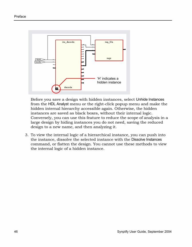
LO
Preface
46 Synplify User Guide, September 2004
Before you save a design with hidden instances, select Unhide Instances from the HDL Analyst menu or the right-click popup menu and make the hidden internal hierarchy accessible again. Otherwise, the hidden instances are saved as black boxes, without their internal logic. Conversely, you can use this feature to reduce the scope of analysis in a large design by hiding instances you do not need, saving the reduced design to a new name, and then analyzing it.
3. To view the internal logic of a hierarchical instance, you can push into the instance, dissolve the selected instance with the Dissolve Instances command, or flatten the design. You cannot use these methods to view the internal logic of a hidden instance.
‘H’ indicates a hidden instance

Preface
Synplify User Guide, September 2004 47
4. If the result of filtering or dissolving is a hollow box with no internal logic, try either of the following, as appropriate, to view the internal hierarchy:
– Select Options->Schematic Options->Sheet Size and increase the value of Maximum Filtered Instances. Use this option if the view is not too cluttered.
– Use the sheet navigation commands to go to the sheets indicated in the hollow box.
If there is too much internal logic to display in the current view, the software puts the internal hierarchy on separate schematic sheets. It displays a hollow box with no internal logic and indicates the schematic sheets that contain the internal logic.
5. To view the design context of an instance in a filtered view, select the instance, right-click, and select Show Context from the popup menu.
The software displays an unfiltered view of the hierarchical level that contains the selected object, with the instance highlighted. This is useful when you have to go back and forth between different views during analysis. The context differs from the Expand commands, which show connections. To return to the original filtered view, click Back.
Pushing into an instance
Generates a view that shows only the internal logic. You do not see the internal hierarchy in context. To return to the previous view, click Back. See Exploring Object Hierarchy by Pushing/Popping, on page 4-25 for details.
Flattening the entire design
Opens a new view where the entire design is flattened, except for hidden hierarchy. Large flattened designs can be overwhelming. See Flattening Schematic Hierarchy, on page 4-56 for details about flattening designs. Because this is a new view, you cannot use Back to return to the previous view. To return to the top-level unflattened schematic, right-click in the view and select Unflatten Schematic.
Flattening an instance by dissolving
Generates a view where the hierarchy of the selected instances is flattened, but the rest of the design is unaffected. This provides context. See Flattening Schematic Hierarchy, on page 4-56 for details about dissolving instances.

LO
Preface
48 Synplify User Guide, September 2004
Filtering SchematicsFiltering is a useful first step in analysis, because it focuses analysis on the relevant parts of the design. Some commands, like the Expand commands, automatically generate filtered views; this procedure only discusses manual filtering, where you use the Filter Schematic command to isolate selected objects. See Chapter 3 of the Synplify Reference Manual for details about these commands.
This table lists the advantages of using filtering over flattening:
1. Select the objects that you want to isolate. For example, you can select two connected objects.
If you filter a hidden instance, the software does not display its internal hierarchy when you filter the design. The following example illustrates this.
Filter Schematic Command Flatten Commands
Loads part of the design; better memory usage
Loads entire design
Combine filtering with Push/Pop mode, and history buttons (Back and Forward) to move freely between hierarchical levels
Must use Unflatten Schematic to return to top level, and flatten the design again to see lower levels. Cannot return to previous view if the previous view is not the top-level view.

Preface
Synplify User Guide, September 2004 49
2. Select the Filter Schematic command, using one of these methods:
– Select Filter Schematic from the HDL Analyst menu or the right-click popup menu.
– Click the Filter Schematic icon (buffer gate) ( ).
– Press F12.
– Press Alt and draw a narrow V-shaped mouse stroke in the schematic window. See Help->Mouse Stroke Tutor for details.
The software filters the design and displays the selected objects in a filtered view. The title bar indicates that it is a filtered view. Hidden instances have an H in the lower left. The view displays other hierar-chical instances as hollow boxes with nested internal logic (transparent instances). For descriptions of filtered views and transparent instances, see Filtered and Unfiltered Schematic Views, on page 6-2 and Trans-parent and Opaque Display of Hierarchical Instances, on page 6-7 in the Synplify Reference Manual. If the transparent instance does not display internal logic, use one of the alternatives described in Viewing Design Hierarchy and Context, on page 4-44, step 4.
3. If the filtered view does not display the pin names of technology primitives and transparent instances that you want to see, do the following:
– Select Options->Schematic Options->Text and enable Show Pin Name.
Filtered view

LO
Preface
50 Synplify User Guide, September 2004
– To temporarily display a pin name, move the cursor over the pin. The name is displayed as long as the cursor remains over the pin. Alternatively, select a pin. The software displays the pin name until you make another selection. Either of these options can be applied to individual pins. Use them to view just the pin names you need and keep design clutter to a minimum.
– To see all the hierarchical pins, select the instance, right-click, and select Show All Hier Pins.
You can now analyze the problem, and do operations like the following:
4. To return to the previous schematic view, click the Back icon. If you flattened the hierarchy, right-click and select Unflatten Schematic to return to the top-level unflattened view.
For additional information about filtering schematics, see Filtering Schematics, on page 4-48 and Flattening Schematic Hierarchy, on page 4-56 of the Synplify Reference Manual.
Expanding Pin and Net LogicWhen you are working in a filtered view, you might need to include more logic in your selected set to debug your design. This section describes commands that expand logic fanning out from pins or nets; to expand paths, see Expanding and Viewing Connections, on page 4-54.
Trace paths, build up logic See Expanding Pin and Net Logic, on page 4-50 and Expanding and Viewing Connections, on page 4-54
Filter further Select objects and filter again
Find objects See Finding Objects, on page 4-30
Flatten, or hide and flatten See Flattening Schematic Hierarchy, on page 4-56. You can hide transparent or opaque instances.
Crossprobe from filtered view
See Crossprobing from the RTL/Technology View, on page 4-40
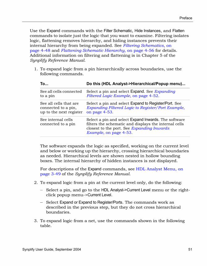
Preface
Synplify User Guide, September 2004 51
Use the Expand commands with the Filter Schematic, Hide Instances, and Flatten commands to isolate just the logic that you want to examine. Filtering isolates logic, flattening removes hierarchy, and hiding instances prevents their internal hierarchy from being expanded. See Filtering Schematics, on page 4-48 and Flattening Schematic Hierarchy, on page 4-56 for details. Additional information on filtering and flattening is in Chapter 5 of the Synplify Reference Manual.
1. To expand logic from a pin hierarchically across boundaries, use the following commands.
The software expands the logic as specified, working on the current level and below or working up the hierarchy, crossing hierarchical boundaries as needed. Hierarchical levels are shown nested in hollow bounding boxes. The internal hierarchy of hidden instances is not displayed.
For descriptions of the Expand commands, see HDL Analyst Menu, on page 3-49 of the Synplify Reference Manual.
2. To expand logic from a pin at the current level only, do the following:
– Select a pin, and go to the HDL Analyst->Current Level menu or the right-click popup menu->Current Level.
– Select Expand or Expand to Register/Ports. The commands work as described in the previous step, but they do not cross hierarchical boundaries.
3. To expand logic from a net, use the commands shown in the following table.
To... Do this (HDL Analyst->Hierarchical/Popup menu)...
See all cells connected to a pin
Select a pin and select Expand. See Expanding Filtered Logic Example, on page 4-52.
See all cells that are connected to a pin, up to the next register
Select a pin and select Expand to Register/Port. See Expanding Filtered Logic to Register/Port Example, on page 4-53.
See internal cells connected to a pin
Select a pin and select Expand Inwards. The software filters the schematic and displays the internal cells closest to the port. See Expanding Inwards Example, on page 4-53.

LO
Preface
52 Synplify User Guide, September 2004
– To expand at the current level and below, select the commands from the HDL Analyst->Hierarchical menu or the right-click popup menu.
– To expand at the current level only, select the commands from the HDL Analyst->Current Level menu or the right-click popup menu->Current Level.
Expanding Filtered Logic Example
To... Do this...
Select the driver of a net
Select a net and select Select Net Driver. The result is a filtered view with the net driver selected (Selecting the Net Driver Example, on page 4-54).
Trace the driver, across sheets if needed
Select a net and select Go to Net Driver. The software shows a view that includes the net driver.
Select all instances on a net
Select a net and select Select Net Instances. You see a filtered view of all instances connected to the selected net.

Preface
Synplify User Guide, September 2004 53
Expanding Filtered Logic to Register/Port Example
Expanding Inwards Example

LO
Preface
54 Synplify User Guide, September 2004
Selecting the Net Driver Example
Expanding and Viewing ConnectionsThis section describes commands that expand logic between two or more objects; to expand logic out from a net or pin, see Expanding Pin and Net Logic, on page 4-50. You can also isolate the critical path or use the Timing Analyst to generate a schematic for a path between objects, as described in Analyzing Timing, on page 4-61.
Use the following path commands with the Filter Schematic and Hide Instances commands to isolate just the logic that you want to examine. The two techniques described here differ: Expand Paths expands connections between selected objects, while Isolate Paths pares down the current view to only display connections to and from the selected instance.
For detailed descriptions of the commands mentioned here, see Commands That Result in Filtered Schematics, on page 6-28 in the Synplify Reference Manual.
1. To expand and view connections between selected objects, do the following:
– Select two or more points.
– To expand the logic at the current level only, select HDL Analyst-> Current Level->Expand Paths or popup menu->Current Level Expand Paths.
– To expand the logic at the current level and below, select HDL Analyst-> Hierarchical->Expand Paths or popup menu->Expand Paths.
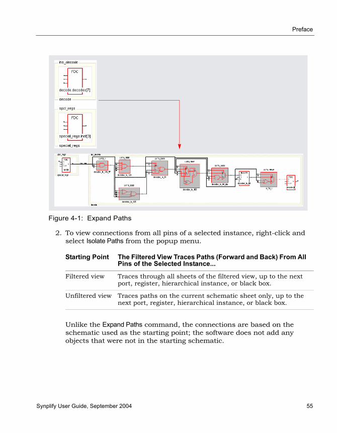
Preface
Synplify User Guide, September 2004 55
Figure 4-1: Expand Paths
2. To view connections from all pins of a selected instance, right-click and select Isolate Paths from the popup menu.
Unlike the Expand Paths command, the connections are based on the schematic used as the starting point; the software does not add any objects that were not in the starting schematic.
Starting Point The Filtered View Traces Paths (Forward and Back) From All Pins of the Selected Instance...
Filtered view Traces through all sheets of the filtered view, up to the next port, register, hierarchical instance, or black box.
Unfiltered view Traces paths on the current schematic sheet only, up to the next port, register, hierarchical instance, or black box.

LO
Preface
56 Synplify User Guide, September 2004
Flattening Schematic HierarchyFlattening removes hierarchy so you can view the logic without hierarchical levels. In most cases, you do not have to flatten your hierarchical schematic to debug and analyze your design, because you can use a combination of filtering, Push/Pop mode, and expanding to view logic at different levels. However, if you must flatten the design, use the following techniques., which include flattening, dissolving, and hiding instances.
1. To flatten an entire design down to logic cells, use one of the following commands:
– For an RTL view, select HDL Analyst->RTL->Flattened View. This flattens the design to generic logic cells.
– For a Technology view, select Flattened View or Flattened to Gates View from the HDL Analyst->Technology menu. Use the former command to flatten the design to the technology primitive level, and the latter command to flatten it further to the equivalent Boolean logic.
The software flattens the top-level design and displays it in a new window. To return to the top-level design, right-click and select Unflatten Schematic.
Unless you really need the entire design flattened, use Push/Pop mode and the filtering commands (Filtering Schematics, on page 4-48) to view the hierarchy. Alternatively, you can use one of the selective flattening techniques described in subsequent steps.
2. To selectively flatten transparent instances when you analyze critical paths or use the Expand commands, select Flatten Current Schematic from the HDL Analyst menu, or select Flatten Schematic from the right-click popup menu.
The software generates a new view of the current schematic in the same window, with all transparent instances at the current level and below flattened. RTL schematics are flattened down to generic logic cells and Technology views down to technology primitives. If you want to control the number of hierarchical levels that are flattened, use the Dissolve Instances command described in step 4.
If your view only contains hidden hierarchical instances or pale yellow (opaque) hierarchical instances, nothing is flattened. If you flatten an unfiltered (usually the top-level design) view, the software flattens all
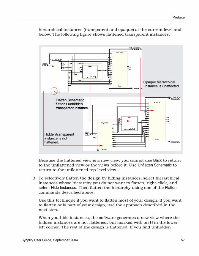
Preface
Synplify User Guide, September 2004 57
hierarchical instances (transparent and opaque) at the current level and below. The following figure shows flattened transparent instances.
Because the flattened view is a new view, you cannot use Back to return to the unflattened view or the views before it. Use Unflatten Schematic to return to the unflattened top-level view.
3. To selectively flatten the design by hiding instances, select hierarchical instances whose hierarchy you do not want to flatten, right-click, and select Hide Instances. Then flatten the hierarchy using one of the Flatten commands described above.
Use this technique if you want to flatten most of your design. If you want to flatten only part of your design, use the approach described in the next step.
When you hide instances, the software generates a new view where the hidden instances are not flattened, but marked with an H in the lower left corner. The rest of the design is flattened. If you find unhidden
Flatten Schematic flattens unhidden transparent instance.
Hidden transparent instance is not flattened.
Flatten Schematic flattens unhidden transparent instance.
Opaque hierarchical instance is unaffected.
LO
Preface
58 Synplify User Guide, September 2004
hierarchical instances are not flattened by this procedure, use the Flattened View or Flattened to Gates View commands described in step 1 instead of the Flatten Current Schematic command described in step 2, which only flattens transparent instances in filtered views.
You can select the hidden instances, right-click, and select Unhide Instances to make their hierarchy accessible again. To return to the unflattened top-level view, right-click in the schematic and select Unflatten Schematic.
4. To selectively flatten some hierarchical instances in your design by dissolving them, do the following:
– If you want to flatten more than one level, select Options->Schematic Options and change the value of Dissolve Levels. If you want to flatten just one level, leave the default setting.
– Select the instances to be flattened.
– Right-click and select Dissolve Instances.
The results differ slightly, depending on the kind of view from which you dissolve instances.
Starting View Software Generates a...
Filtered Filtered view with the internal logic of dissolved instances displayed within hollow bounding boxes (transparent instances), and the hierarchy of the rest of the design unchanged. If the transparent instance does not display internal logic, use one of the alternatives described in step 4 of Viewing Design Hierarchy and Context, on page 4-44. Use the Back button to return to the undissolved view.
Unfiltered New, flattened view with the dissolved instances flattened in place (no nesting) to Boolean logic, and the hierarchy of the rest of the design unchanged. Select Unflatten Schematic to return to the top-level unflattened view. You cannot use the Back button to return to previous views because this is a new view.

Preface
Synplify User Guide, September 2004 59
The following figure illustrates this.
Use this technique if you only want to flatten part of your design while retaining context. If you want to flatten most of the design, use the technique described in the previous step. Instead of dissolving instances, you can use a combination of the filtering commands and Push/Pop mode.
Dissolved logic for prgmcntr, shown nested when you start from a filtered view.
Dissolved logic for prgmcntr, shown flattened in context when you start from an unfiltered view.

LO
Preface
60 Synplify User Guide, September 2004
Minimizing Memory Usage While Analyzing DesignsWhen working with large hierarchical designs, use the following techniques to use memory resources efficiently.
• Before you do any analysis operations like searching, flattening, expanding, or pushing/popping, hide (HDL Analyst->Hide Instances) the hierarchical instances you do not need. This saves memory resources, because the software does not load the hierarchy of the hidden instances.
• Temporarily divide your design into smaller working files. Before you do any analysis, hide the instances you do not need. Save the design. The .srs and .srm files generated are smaller because the software does not save the hidden hierarchy. Close any open HDL Analyst windows, to free all memory from the large design. In the Implementation Results view, double-click one of the smaller files to open the RTL or Technology schematic. Analyze the design using the smaller, working schematics.
• Filter your design instead of flattening it. If you have to flatten your design, hide the instances whose hierarchy you do not need before flattening, or use the Dissolve Instances command. See Flattening Schematic Hierarchy, on page 4-56 for details. For more information on the Expand Paths and Isolate Paths commands, see RTL View and Technology View Popup Menu Commands, on page 3-98 of the Synpli-fyReference Manual.
• When searching your design, search by instance rather than by net. Searching by net loads the entire design, which uses memory.
• Limit the scope of a search by hiding instances you do not need to analyze. You can limit the scope further by filtering the schematic in addition to hiding the instances you do not want to search.
Preface
Synplify User Guide, September 2004 61
Analyzing TimingYou can use the Timing Analyst and HDL Analyst functionality to analyze timing. This section describes the following:
• Analyzing Clock Trees in the RTL View, next
• Viewing Critical Paths, on page 4-62
• Handling Negative Slack, on page 4-65
Analyzing Clock Trees in the RTL View1. In the RTL view Hierarchy Browser, expand Clock Tree, select all the
clocks, and filter the design.
The Hierarchy Browser lists all clocks and the instances that drive them under Clock Tree. The filtered view shows the selected objects.
2. If necessary, use the filter and expand commands to trace clock connections back to the ports and check them.
For details about the commands for filtering and expanding paths, see Filtering Schematics, on page 4-48, Expanding Pin and Net Logic, on page 4-50 and Expanding and Viewing Connections, on page 4-54. For more information on filtering schematics, see HDL Analyst Menu: Filtering and Flattening Commands, on page 3-53 of the Synplify Refer-ence Manual.
3. Check that your defined clock constraints cover the objects in the design.
If you do not define your clock constraints accurately, you might not get the best possible synthesis optimizations.

LO
Preface
62 Synplify User Guide, September 2004
Viewing Critical PathsThe HDL Analyst tool makes it simple to find and examine critical paths and the relevant source code. The following procedure shows you how to filter and analyze a critical path.
1. If needed, set the slack time for your design.
– Select HDL Analyst->Set Slack Margin.
– To view only instances with the worst-case slack time, enter a zero.
– To set a slack margin range, type a value for the slack margin, and click OK. The software gets a range by subtracting this number from the slack time, and the Technology view displays instances within this range. For example, if your slack time is -10 ns, and you set a slack margin of 4 ns, the command displays all instances with slack times between -6 ns and -10 ns. If your slack margin is 6 ns, you see all instances with slack times between -4 ns and -10 ns.
2. Display the critical path using one of the following methods. The Technology view displays a hierarchical view that highlights the instances and nets in the most critical path of your design.
– To generate a hierarchical view of the critical path, click the Show Critical Path icon (stopwatch icon ), select HDL Analyst-> Technology->Hierarchical Critical Path or select the command from the popup menu. This is a filtered view in the same window, with hierarchical logic shown in transparent instances. History commands apply, so you can return to the previous view by clicking Back.
– To flatten the hierarchical critical path described above, right-click and select Flatten Schematic. The software generates a new view in the current window, and flattens only the transparent instances needed to show the critical path; the rest of the design remains hierarchical. Click Back to go the top-level design.
– To generate a flattened critical path in a new window, select HDL Analyst->Technology->Flattened Critical Path. This uses more memory because it flattens the entire design and generates a new view for the flattened critical path in a new window. Click Back in this window to go to the flattened top-level design, or return to the previous window.

Preface
Synplify User Guide, September 2004 63
3. Use the timing numbers displayed above each instance to analyze the path. If no numbers are displayed, enable HDL Analyst->Show Timing Information. Interpret the numbers as follows:
4. View instances in the critical path that have less than the worst-case slack time. For additional information on handling slack times, see Handling Negative Slack, on page 4-65.
If necessary change the slack margin and regenerate the critical path.
5. Crossprobe and check the RTL view and source code. Analyze the code and the schematic to determine how to address the problem. You can add more constraints or make code changes.
Flattened Critical Path
Hierarchical Critical Path
8.8, 1.2
DelayFor combinational logic, it is the cumulative delay to the output of the instance, including the net delay of the output. For flip-flops, it is the portion of the path delay attributed to the flip flop. The delay can be associated with either the input path or output path, whichever is worse, because the flip flop is the end of one path and the start of another.
Slack timeSlack of the worst path that goes through the instance. A negative value indicates that timing has failed.

LO
Preface
64 Synplify User Guide, September 2004
6. Click the Back icon to return to the previous view. If you flattened your design during analysis, select Unflatten Schematic to return to the top-level design.
There is no need to regenerate the critical path, unless you flattened your design during analysis or changed the slack margin. When you flatten your design, the view is regenerated so the history commands do not apply and you must click the Critical Path icon again to see the critical path view.
7. Rerun synthesis, and check your results.
If you have fixed the path, the window displays the next most critical path when you click the icon.
Repeat this procedure and fix the design for the remaining critical paths. When you are within 5-10 percent of your desired results, place and route your design to see if you meet your goal. If so, you are done. If your vendor provides timing-driven place and route, you might improve your results further by adding timing constraints to place and route.
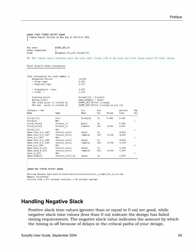
Preface
Synplify User Guide, September 2004 65
Handling Negative SlackPositive slack time values (greater than or equal to 0 ns) are good, while negative slack time values (less than 0 ns) indicate the design has failed timing requirements. The negative slack value indicates the amount by which the timing is off because of delays in the critical paths of your design.
LO
Preface
66 Synplify User Guide, September 2004
The following procedure shows you how to add constraints to fix negative slack. Timing constraints can improve your design by 10% to 20%.
1. Display the critical path in a filtered Technology view.
– For a hierarchical critical path, either click the Critical Path icon, select HDL Analyst-> Show Critical Path, or select HDL Analyst->Technology-> Hierarchical Critical Path.
– For a flat path, select HDL Analyst->Technology->Flattened Critical Path.
2. Analyze the critical path.
– Check the end points of the path. The start point can be a primary input or a flip-flop. The end point can be a primary output or a flip-flop.
– Examine the instances. Use the commands described in Filtering Schematics, on page 4-48, Expanding Pin and Net Logic, on page 4-50, and Expanding and Viewing Connections, on page 4-54. For more information on filtering schematics, see Filtering Schematics, on page 4-48.
3. Determine whether there is a timing exception, like a false or multicycle path. If this is the cause of the negative slack, set the appropriate timing constraint.
If there are fewer start points, pick a start point to add the constraint. If there are fewer end points, add the constraint to an end point.
4. If your design does not meet timing by 20% or more, you might need to make structural changes. You could do this by
– Enabling options like resource sharing.
– Modifying the source code.
5. Rerun synthesis and check your results.

Synplify User Guide, September 2004 1
C H A P T E R 5
Design Optimization
This chapter covers techniques for optimizing your design using built-in tools or attributes. For vendor-specific optimizations, see Chapter 6, Vendor-Specific Optimizations.
It describes the following:
• Design Guidelines, on page 5-2
• Optimizing Results, on page 5-5
• Defining State Machines for Synthesis, on page 5-13
• Using the Symbolic FSM Compiler, on page 5-17
• Defining Black Boxes for Synthesis, on page 5-22
LO
Preface
2 Synplify User Guide, September 2004
Design GuidelinesThe software automatically makes efficient tradeoffs to achieve the best results. However, you can optimize your results by using the appropriate control parameters. This section describes general design guidelines for optimization. The topics have been categorized as follows:
• General Optimization Tips, next
• Area Optimization Tips, on page 5-3
• Timing Optimization Settings, on page 5-4
General Optimization TipsThis section contains general optimization tips that are not directly area or timing-related. For area optimization tips, see Area Optimization Tips, on page 5-3. For timing optimization, see Timing Optimization Settings, on page 5-4.
• In your source code, remove any unnecessary priority structures in timing-critical designs. For example, use CASE statements instead of nested IF-THEN-ELSE statements for priority-independent logic.
• If your design includes safe state machines, use the syn_encoding attribute with a value of safe. This ensures that the synthesized state machines never lock in an illegal state.
• For FSMs coded in VHDL using enumerated types, use the same encoding style (syn_enum_encoding attribute value) on both the state machine enumerated type and the state signal. This ensures that there are no discrepancies in the type of encoding to negatively affect the final circuit.
• Make sure that the source code supports inferencing or instantiation by using architecture-specific resources like memory blocks.
• Some designs benefit from hierarchical optimization techniques. To enable hierarchical optimization on your design, set the syn_hier attribute to firm.
Preface
Synplify User Guide, September 2004 3
• For timing-driven synthesis, explicitly define the clock frequency with a constraint. The software does not use the global clock frequency for timing-driven synthesis.
Area Optimization TipsThis section contains information on optimizing to reduce area. Optimizing for area often means larger delays, and you will have to weigh your perfor-mance needs against your area needs to determine what works best for your design. For tips on optimizing for performance, see Timing Optimization Settings, on page 5-4. General optimization tips are in General Optimization Tips, on page 5-2.
• Increase the fanout limit when you set the implementation options. A higher limit means less replicated logic and fewer buffers inserted during synthesis, and a consequently smaller area. In addition, as P&R tools typically buffer high fanout nets, there is no need for excessive buffering during synthesis. See Setting Fanout Limits, on page 5-7 for more infor-mation.
• Check the Resource Sharing option when you set implementation options. With this option checked, the software shares hardware resources like adders, multipliers, and counters wherever possible, and minimizes area.See Sharing Resources, on page 5-5 for details.
• For designs with large FSMs, use the gray or sequential encoding styles, because they typically use the least area. For details, see Specifying FSMs with Attributes and Directives, on page 5-15.
• If you are mapping into a CPLD and do not meet area requirements, set the default encoding style for FSMs to sequential instead of onehot. For details, see Specifying FSMs with Attributes and Directives, on page 5-15.
• For small CPLD designs (less than 20K gates), you might improve area by using the syn_hier attribute with a value of flatten. When specified, the software optimizes across hierarchical boundaries and creates smaller designs.
LO
Preface
4 Synplify User Guide, September 2004
Timing Optimization SettingsThis section contains information on optimizing to meet timing requirements. Optimizing for timing is often at the expense of area, and you will have to balance the two to determine what works best for your design. For tips on optimizing for area, see Area Optimization Tips, on page 5-3. General optimi-zation tips are in General Optimization Tips, on page 5-2.
• Use realistic design constraints, about 10 - 15% of the real goal. Overconstraining your design can be counter-productive because you can get poor implementations. Use clock, false path, and multicycle path constraints to make the constraints realistic.
• Select a balanced fanout constraint. A large constraint creates nets with large fanouts, and a low fanout constraint results in replicated logic. See Setting Fanout Limits, on page 5-7 for information about setting limits.
• If the critical path goes through arithmetic components, try disabling Resource Sharing. You can get faster times at the expense of increased area, but use this technique carefully. Adding too many resources can cause longer delays and defeat your purpose.
• If the P&R and Synplify tools report different critical paths, use a timing constraint with the -route option. With this option, the software adds route delay to its calculations when trying to meet the clock frequency goal. Use realistic values for the constraints.
• For FSMs, use the onehot encoding style, because it is often the fastest implementation. If a large output decoder follows an FSM, gray or sequential encoding could be faster.
• For designs with black boxes, characterize the timing models accurately, using the syn_tpd, syn_tco, and syn_tso directives.
• If you saw warnings about feedback muxes being created for signals when you compiled your source code, make sure to assign set/resets for the signals. This improves performance by eliminating the extra mux delay on the input of the register.
• Make sure that you pass your timing constraints to the place-and-route tools, so that they can use the constraints to optimize timing.

Preface
Synplify User Guide, September 2004 5
Optimizing ResultsYou can optimize your results with attributes and directives, some of which are specific to the technology you are using. Similarly, you can use specify objects or hierarchy that you want to preserve during synthesis. For a complete list of all the directives and attributes, see the Reference Manual. This section describes the following:
• Sharing Resources, next
• Setting Fanout Limits, on page 5-7
• Controlling Buffering and Replication, on page 5-9
• Controlling Hierarchy Flattening, on page 5-10
• Preserving Objects from Optimization, on page 5-10
• Preserving Hierarchy, on page 5-12
Sharing ResourcesOne of the ways you can optimize area is to use resource sharing. With resource sharing, the software uses the same arithmetic operators for mutually exclusive statements; for example, with the branches of a case statement. Conversely, you can improve timing by disabling resource sharing, but at the expense of increased area.
1. Specify resource sharing globally for the whole design with one of the methods below. Enable the option to improve area; disable it to improve timing.
– Select Project->Implementation Options->Options, and enable or disable Resource Sharing. Alternatively, enable Resource Sharing in the Project view.
– Apply the syn_sharing directive to the top-level module or architecture in the source code. See syn_sharing, on page 8-88 of the Synplify Reference Manual for syntax examples.
Verilog module top(out, in, clk_in) /* synthesis syn_sharing = “on” */;
VHDL architecture rtl of top is attribute syn_sharing : string; attribute syn_sharing of rtl : architecture is “off”;
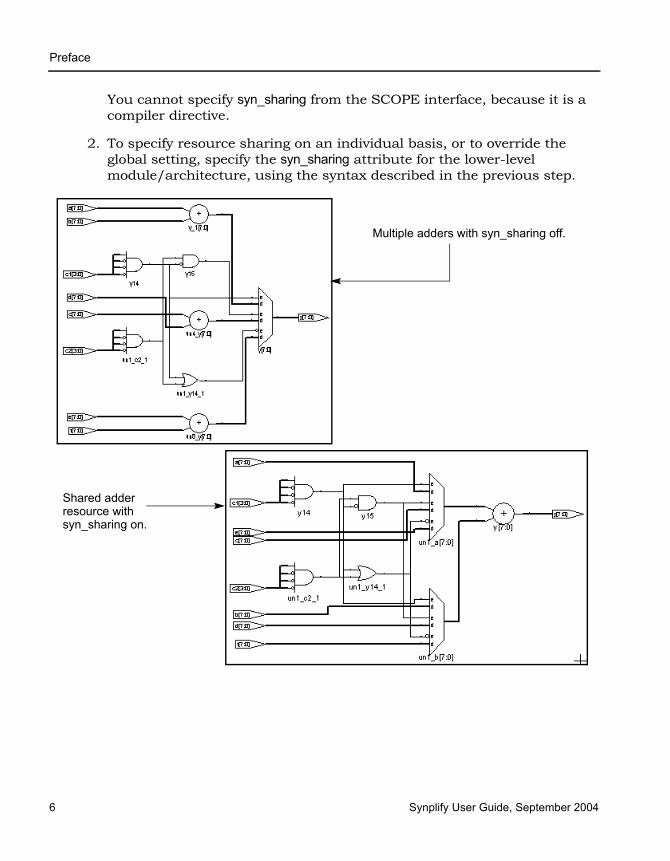
LO
Preface
6 Synplify User Guide, September 2004
You cannot specify syn_sharing from the SCOPE interface, because it is a compiler directive.
2. To specify resource sharing on an individual basis, or to override the global setting, specify the syn_sharing attribute for the lower-level module/architecture, using the syntax described in the previous step.
Multiple adders with syn_sharing off.
Shared adder resource with syn_sharing on.

Preface
Synplify User Guide, September 2004 7
Setting Fanout LimitsOptimization affects net fanout. If your design has critical nets with high fanout, you can set fanout limits. You can only do this in certain technologies. For details specific to individual technologies, see the Synplify Reference Manual.
1. To set a global fanout limit for the whole design, do either of the following:
– Select Project-> Implementation Options->Device and type a value for the Fanout Guide option.
– Apply the syn_maxfan attribute to the top-level view or module.
The value sets the number of fanouts for a given driver, and affects all the nets in the design. The defaults vary, depending on the technology. Select a balanced fanout value. A large constraint creates nets with large fanouts, and a low fanout constraint results in replicated or buffered logic. Both extremes affect routing and design performance. The right value depends on your design. The same value of 32 might result in fanouts of 11 or 12 and large delays on the critical path in one design or in excessive replication in another design.
The software uses the value as a soft limit, or a guide. It traverses the inverters and buffers to identify the fanout, and tries to ensure that all fanouts are under the limit by replicating or buffering where needed (see Controlling Buffering and Replication, on page 5-9 for details). However, the synthesis tool does not respect the fanout limit absolutely; it ignores the limit if the limit imposes constraints that interfere with optimization.
2. For certain Actel technologies, you can set a global hard fanout limit by doing the following:
– Select Project-> Implementation Options->Device and type a value for the Fanout Guide option, as described in the previous step.
– On the same tab, check the Hard Fanout Limit option.
This makes the specified value a global hard fanout limit for the design.
3. To override the global fanout guideline and set a soft fanout limit at a lower level, set the syn_maxfan attribute on modules, views, or non-primitive instances.

LO
Preface
8 Synplify User Guide, September 2004
These limits override the more global limits for that object (including a global hard limit in Actel technologies). However, these limits still function as soft limits, and are replicated or buffered, as described in Controlling Buffering and Replication, on page 5-9.
4. To set a hard or absolute limit, set the syn_maxfan attribute on a port, net, register, or primitive instance.
Fanouts that exceed the hard limit are buffered or replicated, as described in Controlling Buffering and Replication, on page 5-9p.
5. To preserve net drivers from being optimized, attach the syn_keep or syn_preserve attributes.
For example, the software does not traverse a syn_keep buffer (inserted as a result of the attribute), and does not optimize it. However, the software can optimize implicit buffers created as a result of other opera-tions; for example, it does not respect an implicit buffer created as a result of syn_direct_enable.
6. Check the results of buffering and replication in
– The log file (click View Log). The log file reports the number of buffered and replicated objects and the number of segments created for the net.
– The HDL Analyst views. The software might not follow DRC rules when buffering or replicating objects, or when obeying hard fanout limits.
Attribute specified on... Effect
Module or view Soft limit for the module; overrides the global setting.
Non-primitive instance Soft limit; overrides global and module settings
Clock nets or asynchronous control nets
Soft limit.

Preface
Synplify User Guide, September 2004 9
Controlling Buffering and ReplicationTo honor fanout limits (see Setting Fanout Limits, on page 5-7) and reduce fanout, the software either replicates components or adds buffers. The software reduces fanout on input ports through buffering and reduces fanout on nets driven by registers or combinatorial logic through replication. The software first tries replication, replicating the net driver and splitting the net into segments. This increases the number of register bits in the design. When replication is not possible, the software buffers the signals. Buffering is more expnsive in terms of intrinsic delay and resource consumption. The following table summarizes the behavior.
You can control whether high fanout nets are buffered or replicated, using the techniques described here:
• To use buffering instead of replication, set syn_replicate with a value of 0 globally, or on modules or registers. The syn_replicate attribute prevents replication, so that the software uses buffering to satisfy the fanout limit. For example, you can prevent replication between clock boundaries for a register that is clocked by clk1 but whose fanin cone is driven by clk2, even though clk2 is an unrelated clock in another clock group.
• To specify that high-fanout clock ports should not be buffered, set syn_noclockbuf globally, or on individual input ports. Use this if you want to save clock buffer resources for nets with lower fanouts but tighter constraints.
• Turn off buffering and replication entirely, by setting syn_maxfan to a very high number, like 1000.
Replicates When... Creates Buffers When...
syn_maxfan is set on a register output
syn_maxfan is set on input ports in Actel 54SX and Actel 42MX
syn_replicate is 1 syn_replicate is 0
syn_maxfan is set on a port/net that is driven by a port or I/O pad
The net driver has a syn_keep or syn_preserve attribute
The net driver is not a primitive gate or register
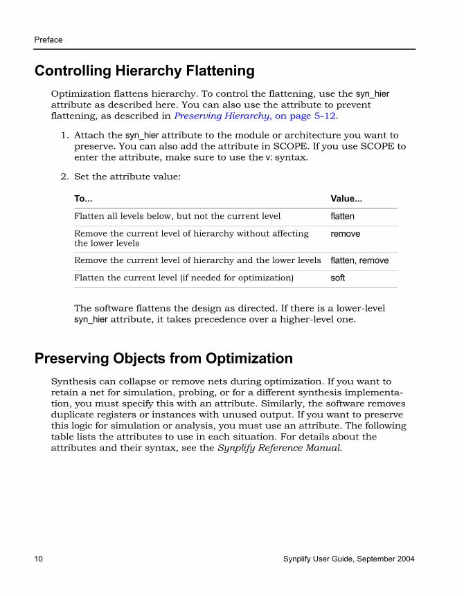
LO
Preface
10 Synplify User Guide, September 2004
Controlling Hierarchy FlatteningOptimization flattens hierarchy. To control the flattening, use the syn_hier attribute as described here. You can also use the attribute to prevent flattening, as described in Preserving Hierarchy, on page 5-12.
1. Attach the syn_hier attribute to the module or architecture you want to preserve. You can also add the attribute in SCOPE. If you use SCOPE to enter the attribute, make sure to use the v: syntax.
2. Set the attribute value:
The software flattens the design as directed. If there is a lower-level syn_hier attribute, it takes precedence over a higher-level one.
Preserving Objects from OptimizationSynthesis can collapse or remove nets during optimization. If you want to retain a net for simulation, probing, or for a different synthesis implementa-tion, you must specify this with an attribute. Similarly, the software removes duplicate registers or instances with unused output. If you want to preserve this logic for simulation or analysis, you must use an attribute. The following table lists the attributes to use in each situation. For details about the attributes and their syntax, see the Synplify Reference Manual.
To... Value...
Flatten all levels below, but not the current level flatten
Remove the current level of hierarchy without affecting the lower levels
remove
Remove the current level of hierarchy and the lower levels flatten, remove
Flatten the current level (if needed for optimization) soft
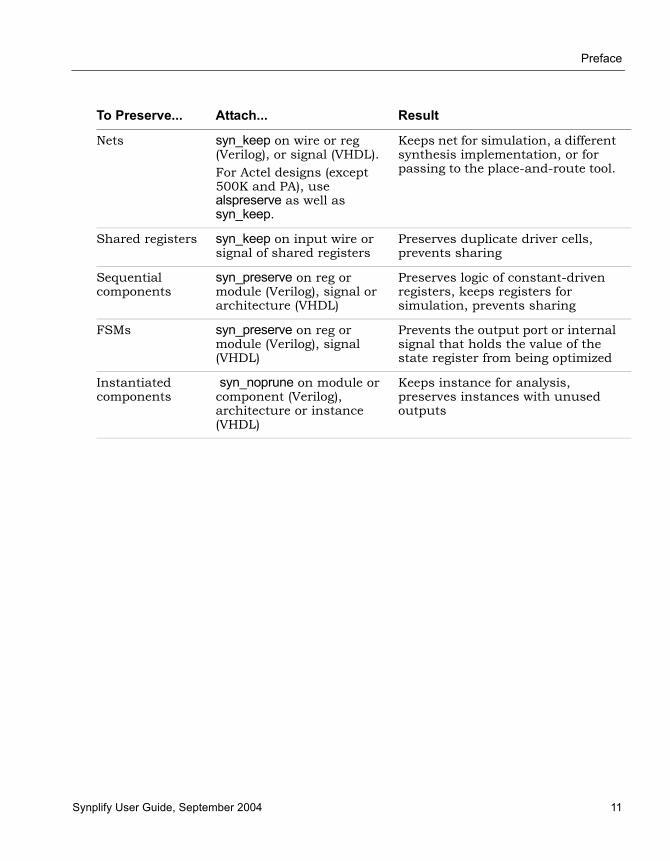
Preface
Synplify User Guide, September 2004 11
To Preserve... Attach... Result
Nets syn_keep on wire or reg (Verilog), or signal (VHDL). For Actel designs (except 500K and PA), use alspreserve as well as syn_keep.
Keeps net for simulation, a different synthesis implementation, or for passing to the place-and-route tool.
Shared registers syn_keep on input wire or signal of shared registers
Preserves duplicate driver cells, prevents sharing
Sequential components
syn_preserve on reg or module (Verilog), signal or architecture (VHDL)
Preserves logic of constant-driven registers, keeps registers for simulation, prevents sharing
FSMs syn_preserve on reg or module (Verilog), signal (VHDL)
Prevents the output port or internal signal that holds the value of the state register from being optimized
Instantiated components
syn_noprune on module or component (Verilog), architecture or instance (VHDL)
Keeps instance for analysis, preserves instances with unused outputs
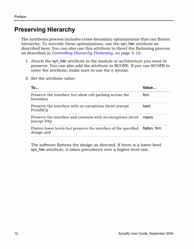
LO
Preface
12 Synplify User Guide, September 2004
Preserving HierarchyThe synthesis process includes cross-boundary optimizations that can flatten hierarchy. To override these optimizations, use the syn_hier attribute as described here. You can also use this attribute to direct the flattening process as described in Controlling Hierarchy Flattening, on page 5-10.
1. Attach the syn_hier attribute to the module or architecture you want to preserve. You can also add the attribute in SCOPE. If you use SCOPE to enter the attribute, make sure to use the v: syntax.
2. Set the attribute value:
The software flattens the design as directed. If there is a lower-level syn_hier attribute, it takes precedence over a higher-level one.
To... Value...
Preserve the interface but allow cell packing across the boundary
firm
Preserve the interface with no exceptions (Actel (except ProASIC))
hard
Preserve the interface and contents with no exceptions (Actel (except PA))
macro
Flatten lower levels but preserve the interface of the specified design unit
flatten, firm

Preface
Synplify User Guide, September 2004 13
Defining State Machines for SynthesisA finite state machine (FSM) is a piece of hardware that advances from state to state at a clock edge. The synthesis software recognizes and extracts the state machines from the HDL source code. For guidelines on setting up the source code, see the following:
• Defining State Machines in Verilog, next
• Defining State Machines in VHDL, on page 5-14
• Specifying FSMs with Attributes and Directives, on page 5-15
For information about the attributes used to define state machines, see Running the FSM Compiler on Individual FSMs, on page 5-19.
Defining State Machines in VerilogThe synthesis software recognizes and automatically extracts state machines from the Verilog source code if you follow these coding guidelines. The software attaches the syn_state_machine attribute to each extracted FSM.
For alternative ways to define state machines, see Defining State Machines in VHDL, on page 5-14 and Specifying FSMs with Attributes and Directives, on page 5-15.
• In Verilog, model the state machine with case, casex, or casez state-ments in always blocks. Check the current state to advance to the next state and then set output values. Do not use if statements.
• Always use a default assignment as the last assignment in the case statement, and set the state variable to ‘bx. This is a “don’t care” state-ment and ensures that the software can remove unnecessary decoding and gates.
• Make sure the state machines have a synchronous or asynchronous reset to set the hardware to a valid state after power-up, or to reset the hardware when you are operating.

LO
Preface
14 Synplify User Guide, September 2004
• Use explicit state values for states using parameter or ‘define state-ments. This is an example of a parameter statement that sets the current state to 2’h2:
parameter state1 = 2’h1, state2 = 2’h2;...current_state = state2;
This example shows how to set the current state value with ‘define statements:
‘define state1 2’h1‘define state2 2’h2...current_state = ‘state2;
Defining State Machines in VHDLThe synthesis software recognizes and automatically extracts state machines from the VHDL source code if you follow coding guidelines. For alternative ways to define state machines, see Defining State Machines in Verilog, on page 5-13 and Specifying FSMs with Attributes and Directives, on page 5-15.
The following are VHDL guidelines for coding. The software attaches the syn_state_machine attribute to each extracted FSM.
• Use CASE statements to check the current state at the clock edge, advance to the next state, and set output values. You can also use IF-THEN-ELSE statements, but CASE statements are preferable.
• If you do not cover all possible cases explicitly, include a WHEN OTHERS assignment as the last assignment of the CASE statement, and set the state vector to some valid state.
• If you create implicit state machines with multiple WAIT statements, the software does not recognize them as state machines.
• Make sure the state machines have a synchronous or asynchronous reset to set the hardware to a valid state after power-up, or to reset the hardware when you are operating.
• To choose an encoding style, attach the syn_encoding attribute to the enumerated type. The software automatically encodes your state machine with the style you specified.

Preface
Synplify User Guide, September 2004 15
Specifying FSMs with Attributes and DirectivesIf your design has state machines, the software can extract them automati-cally with the FSM Compiler (see Using the Symbolic FSM Compiler, on page 5-17), or you can manually specify attributes to define the state machines. You attach the attributes to the state registers. For detailed infor-mation about the attributes and their syntax, see the Synplify Reference Manual.
The following steps show you how to use attributes to define FSMs for extrac-tion. For alternative ways to define state machines, see Defining State Machines in Verilog, on page 5-13 and Defining State Machines in VHDL, on page 5-14.
1. To determine how state machines are extracted, set attributes in the source code as shown in the following table:
For information about how to add attributes, see Adding Attributes and Directives, on page 3-36.
2. To determine the encoding style used for the state machine, set the syn_encoding attribute in the source code or in the SCOPE window. For VHDL users there are alternative methods, described in the next step.
The FSM Compiler honors this setting. The different values for this attribute are briefly described here:
To... Attribute
Specify a state machine for extraction and optimization
syn_state_machine=1
Prevent state machines from being extracted and optimized
syn_state_machine=0
Prevent the state machine from being optimized away
syn_preserve=1

LO
Preface
16 Synplify User Guide, September 2004
3. If you are using VHDL, you have two choices for defining encoding:
– Use syn_encoding as described above, and enable the FSM compiler.
– Use syn_enum_encoding to define the states (sequential, onehot, gray, and safe) and disable the FSM compiler. If you do not disable the FSM compiler, the syn_enum_encoding values are not implemented. This is because the FSM compiler, a mapper operation, overrides syn_enum_encoding, which is a compiler directive.
Use this method for user-defined FSM encoding. For example:
attribute syn_enum_encoding of state_type : type is "001 010 101";
Situation: If... syn_encoding Value Explanation
Area is important sequential One of the smallest encoding styles.
Speed is important
onehot Usually the fastest style and suited to most FPGA styles.
Recovery from an invalid state is important
safe, with another style. For example: /* synthesis syn_encoding = “safe, onehot” */
Forces the state machine to reset. For example, where an alpha particle hit in a hostile operating environment causes a spontaneous register change, you can use safe to reset the state machine.
There are <5 states
sequential Default encoding.
Large output decoder follows the FSM
sequential or gray
Could be faster than onehot, even though the value must be decoded to determine the state. For sequential, more than one bit can change at a time; for gray, only one bit changes at a time, but more than one bit can be hot.
There are a large number of flip-flops
onehot Fastest style, because each state variable has one bit set, and only one bit of the state register changes at a time.

Preface
Synplify User Guide, September 2004 17
Using the Symbolic FSM CompilerThe Symbolic FSM Compiler is an advanced state machine optimizer, which automatically recognizes state machines in your design and optimizes them. Unlike other synthesis tools that treat state machines as regular logic, the FSM Compiler extracts the state machines as symbolic graphs, and then optimizes them by re-encoding the state representations and generating a better logic optimization starting point for the state machines.
For more information, see the following:
• Choosing When to Use the FSM Compiler, on page 5-17, next
• Running the FSM Compiler on the Whole Design, on page 5-18
• Running the FSM Compiler on Individual FSMs, on page 5-19
• Specifying FSMs with Attributes and Directives, on page 5-15
Choosing When to Use the FSM CompilerThe FSM Compiler is an automatic tool for state machines, but you can also specify FSMs manually with attributes. For more information about FSM attributes, see Adding Attributes and Directives, on page 3-36 and Specifying FSMs with Attributes and Directives, on page 5-15.
Here are the main reasons to use the FSM Compiler:
• To generate better results for your state machines
The software uses optimization techniques that are specifically tuned for FSMs, like reachability analysis for example. The FSM Compiler also lets you convert an encoded state machine to another encoding style (to improve speed and area utilization) without changing the source. For example, you can use a onehot style to improve results.
• To debug the state machines
State machine description errors result in unreachable states, so if you have errors, you will have fewer states. You can check whether your source code describes your state machines correctly.
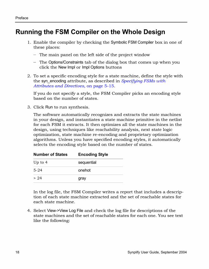
LO
Preface
18 Synplify User Guide, September 2004
Running the FSM Compiler on the Whole Design1. Enable the compiler by checking the Symbolic FSM Compiler box in one of
these places:
– The main panel on the left side of the project window
– The Options/Constraints tab of the dialog box that comes up when you click the New Impl or Impl Options buttons
2. To set a specific encoding style for a state machine, define the style with the syn_encoding attribute, as described in Specifying FSMs with Attributes and Directives, on page 5-15.
If you do not specify a style, the FSM Compiler picks an encoding style based on the number of states.
3. Click Run to run synthesis.
The software automatically recognizes and extracts the state machines in your design, and instantiates a state machine primitive in the netlist for each FSM it extracts. It then optimizes all the state machines in the design, using techniques like reachability analysis, next state logic optimization, state machine re-encoding and proprietary optimization algorithms. Unless you have specified encoding styles, it automatically selects the encoding style based on the number of states.
In the log file, the FSM Compiler writes a report that includes a descrip-tion of each state machine extracted and the set of reachable states for each state machine.
4. Select View->View Log File and check the log file for descriptions of the state machines and the set of reachable states for each one. You see text like the following:
Number of States Encoding Style
Up to 4 sequential
5-24 onehot
> 24 gray
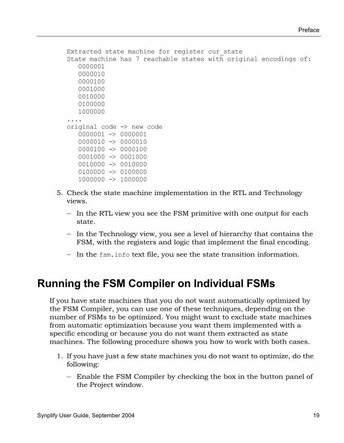
Preface
Synplify User Guide, September 2004 19
Extracted state machine for register cur_stateState machine has 7 reachable states with original encodings of:
0000001000001000001000001000001000001000001000000
....original code -> new code
0000001 -> 00000010000010 -> 00000100000100 -> 00001000001000 -> 00010000010000 -> 00100000100000 -> 01000001000000 -> 1000000
5. Check the state machine implementation in the RTL and Technology views.
– In the RTL view you see the FSM primitive with one output for each state.
– In the Technology view, you see a level of hierarchy that contains the FSM, with the registers and logic that implement the final encoding.
– In the fsm.info text file, you see the state transition information.
Running the FSM Compiler on Individual FSMsIf you have state machines that you do not want automatically optimized by the FSM Compiler, you can use one of these techniques, depending on the number of FSMs to be optimized. You might want to exclude state machines from automatic optimization because you want them implemented with a specific encoding or because you do not want them extracted as state machines. The following procedure shows you how to work with both cases.
1. If you have just a few state machines you do not want to optimize, do the following:
– Enable the FSM Compiler by checking the box in the button panel of the Project window.
LO
Preface
20 Synplify User Guide, September 2004
– If you do not want to optimize the state machine, add the syn_state_machine directive to the registers in the Verilog or VHDL code. Set the value to 0. When synthesized, these registers are not extracted as state machines.
– If you want to specify a particular encoding style for a state machine, use the syn_encoding attribute, as described in Specifying FSMs with Attributes and Directives, on page 5-15. When synthesized, these registers have the specified encoding style.
– Run synthesis.
The software automatically recognizes and extracts all the state machines, except the ones you marked. It optimizes the FSMs it extracted from the design, honoring the syn_encoding attribute. It writes out a log file that contains a description of each state machine extracted, and the set of reachable states for each FSM.
2. If you have many state machines you do not want optimized, do this:
– Disable the compiler by disabling the Symbolic FSM Compiler box in one of these places: the main panel on the left side of the project window or the Options/Constraints tab of the dialog box that comes up when you click the New Impl or Impl Options buttons. This disables the compiler from optimizing any state machine in the design. You can now selectively turn on the FSM compiler for individual FSMs.
– For state machines you want the FSM Compiler to optimize automatically, add the syn_state_machine directive to the individual state registers in the VHDL or Verilog code. Set the value to 1. When synthesized, the FSM Compiler extracts these registers with the default encoding styles according to the number of states.
Verilog reg [3:0] curstate /* synthesis syn_state_machine=0 */ ;
VHDL signal curstate : state_type;attribute syn_state_machine : boolean;attribute syn_state_machine of curstate : signal is false;v
Verilog reg [3:0] curstate /* synthesis syn_state_machine=1 */ ;
VHDL signal curstate : state_type;attribute syn_state_machine : boolean;attribute syn_state_machine of curstate : signal is true;
Preface
Synplify User Guide, September 2004 21
– For state machines with specific encoding styles, set the encoding style with the syn_encoding attribute, as described in Specifying FSMs with Attributes and Directives, on page 5-15. When synthesized, these registers have the specified encoding style.
– Run synthesis.
The software automatically recognizes and extracts only the state machines you marked. It automatically assigns encoding styles to the state machines with the syn_state_machine attribute, and honors the encoding styles set with the syn_encoding attribute. It writes out a log file that contains a description of each state machine extracted, and the set of reachable states for each state machine.
3. Check the state machine in the log file, the RTL and technology views.
LO
Preface
22 Synplify User Guide, September 2004
Defining Black Boxes for SynthesisBlack boxes are predefined components for which the interface is specified, but whose internal architectural statements are ignored. They are used as place holders for IP blocks, legacy designs, or a design under development.
This section discusses the following topics:
• Instantiating Black Boxes and I/Os in Verilog, next
• Instantiating Black Boxes and I/Os in VHDL, on page 5-24
• Adding Black Box Timing Constraints, on page 5-26
• Adding Other Black Box Attributes, on page 5-30
Instantiating Black Boxes and I/Os in Verilog Verilog black boxes for macros and I/Os come from two sources: commonly-used or vendor-specific components that are predefined in Verilog macro libraries, or black boxes that are defined in another input source like a schematic. For information abut instantiating black boxes in VHDL, see Instantiating Black Boxes and I/Os in VHDL, on page 5-24.
The following process shows you how to instantiate both types as black boxes. Refer to the Synplify_install_dir/examples directory for examples of instantiations of low-level resources.
1. To instantiate a predefined Verilog module as a black box:
– Select the library file with the macro you need from the Synplify_install_dir/lib/<technology> directory. Files are named <technology>.v. Most vendor architectures provide macro libraries that predefine the black boxes for primitives and macros.
– Make sure the library macro file is the first file in the source file list for your project.
2. To instantiate a module that has been defined in another input source as a black box:
– Create an empty macro that only contains ports and port directions.
Preface
Synplify User Guide, September 2004 23
– Put the syn_black_box synthesis directive just before the semicolon in the module declaration.
module myram (out, in, addr, we) /* synthesis syn_black_box */;output [15:0] out;input [15:0] in;input [4:0] addr;input we;
endmodule
– Make an instance of the stub in your design.
– Compile the stub along with the module containing the instantiation of the stub.
– To simulate with a Verilog simulator, you must have a functional description of the black box. To make sure the synthesis software ignores the functional description and treats it as a black box, use the translate_off and translate_on constructs. For example:
module adder8(cout, sum, a, b, cin);// Code that you want to synthesize/* synthesis translate_off */// Functional description./* synthesis translate_on */// Other code that you want to synthesize.endmodule
3. To instantiate a vendor-specific (black box) I/O that has been defined in another input source:
– Create an empty macro that only contains ports and port directions.
– Put the syn_black_box synthesis directive just before the semicolon in the module declaration.
– Specify the external pad pin with the black_box_pad_pin directive, as in this example:
module BBDLHS(D,E,GIN,GOUT,PAD,Q)/* synthesis syn_black_box black_box_pad_pin="PAD"
– Make an instance of the stub in your design.
– Compile the stub along with the module containing the instantiation of the stub.

LO
Preface
24 Synplify User Guide, September 2004
4. Add timing constraints and attributes as needed. See Adding Black Box Timing Constraints, on page 5-26 and Adding Other Black Box Attributes, on page 5-30.
5. After synthesis, merge the black box netlist and the synthesis results file using the method specified by your vendor.
Instantiating Black Boxes and I/Os in VHDL VHDL black boxes for macros and I/Os come from two sources: commonly-used or vendor-specific components that are predefined in VHDL macro libraries, or black boxes that are defined in another input source like a schematic. For information abut instantiating black boxes in VHDL, see Instantiating Black Boxes and I/Os in Verilog, on page 5-22.
The following process shows you how to instantiate both types as black boxes. Refer to the Synplify_install_dir/examples directory for examples of instantiations of low-level resources.
1. To instantiate a predefined VHDL macro (for a component or an I/O),
– Select the library file with the macro you need from the Synplify_install_dir/lib/vendor directory. Files are named family.vhd. Most vendor architectures provide macro libraries that predefine the black boxes for primitives and macros.
– Add the appropriate library and use clauses to the beginning of your design units that instantiate the macros.
library family ;use family.components.all;
2. To create a black box for a component from another input source:
– Create a component declaration for the black box.
– Declare the syn_black_box attribute as a boolean attribute.
– Set the attribute to be true.
library synplify;use synplify.attributes.all;entity top is
port (clk, rst, en, data: in bit; q; out bit);end top;

Preface
Synplify User Guide, September 2004 25
architecture structural of top iscomponent bbox
port(Q: out bit; D, C, CLR: in bit);end component;
attribute syn_black_box of bbox: component is true;...
– Instantiate the black box and connect the ports.
beginmy_bbox: my_bbox port map (
Q => q,D => data_core,C => clk,CLR => rst);
– To simulate with a VHDL simulator, you must have the functional description of a black box. To make sure the synthesis software ignores the functional description and treats it as a black box, use the translate_off and translate_on constructs. For example:
architecture behave of ram4 isbegin
synthesis translate_offstimulus: process (clk, a, b)-- Functional description
end process;synthesis translate_on
-- Other source code you WANT synthesized
3. To create a vendor-specific (black box) I/O for an I/O defined in another input source:
– Create a component declaration for the I/O.
– Declare the black_box_pad_pin attribute as a string attribute.
– Set the attribute value on the component to be the external pin name for the pad.
library synplify;use synplify.attributes.all;...
component mybufport(O: out bit; I: in bit);
end component;attribute black_box_pad_pin of mybuf: component is “I”;

LO
Preface
26 Synplify User Guide, September 2004
– Instantiate the pad and connect the signals.
begindata_pad: mybuf port map (
O => data_core,I => data);
4. Add timing constraints and attributes. See Adding Black Box Timing Constraints, on page 5-26 and Adding Other Black Box Attributes, on page 5-30.
Adding Black Box Timing ConstraintsA black box does not provide the software with any information about internal timing characteristics. You must characterize black box timing accurately, because it can critically affect the overall timing of the design. To do this, you add constraints in the source code or in the SCOPE interface.
You attach black box timing constraints to instances that have been defined as black boxes. There are three black box timing constraints, syn_tpd, syn_tsu, and syn_tco. There are additional attributes for black box pins; see Adding Other Black Box Attributes, on page 5-30.
1. Define the instance as a black box, as described in Instantiating Black Boxes and I/Os in Verilog, on page 5-22 or Instantiating Black Boxes and I/Os in VHDL, on page 5-24.
Black Box
D
syn_tpd
syn_tsu
syn_tco
Q
clk

Preface
Synplify User Guide, September 2004 27
2. Determine the kind of constraint for the information you want to specify:
3. In VHDL, use the following syntax for the constraints.
– Use the predefined attributes package by adding this syntax
library synplify;use synplify.attributes.all;
In VHDL, you must use the predefined attributes package. For each directive, there are ten predeclared constraints in the attributes package, from directive_name1 to directive_name10. If you need more constraints, declare the additional constraints using integers greater than 10. For example:
attribute syn_tco11 : string;attribute syn_tco12 : string;
– Define the constraints in either of these ways:
The following table shows the appropriate syntax for att_value. See the Synplify Reference Manual for complete syntax information.
To define... Use...
Propagation delay through the black box syn_tpd
Setup delay (relative to the clock) for input pins syn_tsu
Clock-to-output delay through the black box syn_tco
VHDL syntax
attribute attribute_name<n> : “att_value”
Verilog-style notation
attribute attribute_name<n> of bbox_name : component is "att_value"

LO
Preface
28 Synplify User Guide, September 2004
The following is an example of black box attributes, using VHDL signal notation:
architecture top of top is component rcf16x4z port(
ad0, ad1, ad2, ad3 : in std_logic;di0, di1, di2, di3 : in std_logic;wren, wpe : in std_logic;tri : in std_logic;do0, do1, do2 do3 : out std_logic;
end component
attribute syn_tpd1 of rcf16x4z : component is“ad0,ad1,ad2,ad3 -> do0,do1,do2,do3 = 2.1”;
attribute syn_tpd2 of rcf16x4z : component is“tri -> do0,do1,do2,do3 = 2.0”;
attribute syn_tsu1 of rcf16x4z : component is“ad0,ad1,ad2,ad3 -> ck = 1.2”;
attribute syn_tsu2 of rcf16x4z : component is“wren,wpe,do0,do1,do2,do3 -> ck = 0.0”;
4. In Verilog, add the directives as comments, as shown in the following example. For explanations about the syntax, see the table in the previous step or the Synplify Reference Manual.
module ram32x4 (z, d, addr, we, clk)/* synthesis syn_black_boxsyn_tpd1=”addr[3:0]->z[3:0]=8.0”syn_tsu1=”addr[3:0]->clk=2.0”syn_tsu2=”we->clk=3.0” */;
output [3:0[ z;
Attribute Value Syntax
syn_tsu<n> bundle -> [!]clock = value
syn_tco<n> [!]clock -> bundle = value
syn_tpd<n> bundle -> bundle = value
• <n> is a numerical suffix. • bundle is a comma-separated list of buses and scalar signals, with no
intervening spaces. For example, A,B,C. • ! indicates (optionally) a negative edge for a clock.• value is in ns.

Preface
Synplify User Guide, September 2004 29
input [3:0] d;input [3:0] addr;input we;input clk;endmodule
5. To add black box attributes through the SCOPE interface, do the following:
– Open the SCOPE spreadsheet and select the Attributes panel.
– In th Object column, select the name of the black-box module or component declaration from the pull-down list. Manually prefix the black box name with v: to apply the constraint to the view.
– In the Attribute column, type the name of the timing attribute, followed by the numerical suffix, as shown in the following table. You cannot select timing attributes from the pull-down list.
– In the Value column, type the appropriate value syntax, as shown in the table in step 3.
– Save the constraint file, and add it to the project.
The resulting constraint file contains syntax like this:
define_attribute v:{blackbox_module} attribute<n> {att_value}
6. Synthesize the design, and check black box timing.

LO
Preface
30 Synplify User Guide, September 2004
Adding Other Black Box AttributesBesides black box timing constraints, you can also add other attributes to define pin types on the black box. You cannot use the attributes for all technologies. Check the Synplify Reference Manual for details about which technologies are supported.
1. To specify that a clock pin on the black box has access to global clock routing resources, use syn_isclock.
Depending on the technology, different clock resources are inserted. In Actel, it inserts CLKBUF.
2. To specify that the software need not insert a pad for a black box pin, use black_box_pad_pin.
Use this for technologies that automatically insert pad buffers for the I/Os .
3. To define a tristate pin so that you do not get a mixed driver error when there is another tristate buffer driving the same net, use black_box_tri_pins.
Pad
Clk
Clk buffer
syn_isclock
black_box_tri_pins
Black Box
black_box_pad_pin

Synplify User Guide, September 2004 1
C H A P T E R 6
Vendor-Specific Optimizations
This chapter covers techniques for optimizing your design for various vendors. The information in this chapter is intended to be used together with the information in Chapter 5, Design Optimization.
This chapter describes the following:
• Passing Information to the P&R Tools, on page 6-2
• Generating Vendor-Specific Output, on page 6-4
• Working with Actel Designs, on page 6-4

LO
Preface
2 Synplify User Guide, September 2004
Passing Information to the P&R ToolsThe following procedures show you how to pass information to the place-and-route tool; this information generally has no impact on synthesis. Typically, you use attributes to pass this information to the place-and-route tools. This section describes the following:
• Specifying Pin Locations, on page 6-2
• Specifying Locations for Actel Bus Ports, on page 6-3
• Specifying Macro and Register Placement, on page 6-3
Specifying Pin LocationsYou can specify pin locations that are forward-annotated to the corre-sponding place-and-route tool. The following procedure shows you how to specify the appropriate attributes. For information about other placement properties, see Specifying Macro and Register Placement, on page 6-3.
1. Start with a design using one of the following technologies: 3200DX, 40MX, 42MX, 54SX/SXA, ACT1, ACT2, ACT3, Axcelerator, and EX.
2. Add the appropriate attribute to the port. For a bus, list all the bus pins, separated by commas. To specify Actel bus port locations, see Specifying Locations for Actel Bus Ports, on page 6-3.
– To add the attribute from the SCOPE interface, click the Attributes tab and specify the appropriate attribute and value.
– To add the attribute in the source files, use the appropriate attribute and syntax. See the Synplify Reference Manual for syntax details.
Family Attribute and Value
Actel (except 500K, PA, ProASIC3/3E))
alspin {pin_number}

Preface
Synplify User Guide, September 2004 3
Specifying Locations for Actel Bus Ports You can specify pin locations for Actel bus ports, except the 500K and PA technologies. To assign pin numbers to a bus port, or to a single- or multiple-bit slice of a bus port, do the following:
1. Open the constraint file an add these attributes to the design.
2. Specify the syn_noarrayports attribute globally to bit blast all bus ports in the design.
define_global_attribute syn_noarrayports {1};
3. Use the alspin attribute to specify pin locations for individual bus bits. This example shows locations specified for individual bits of bus ADDRESS0.
define_attribute {ADDRESS0[4]} alspin {26}define_attribute {ADDRESS0[3]} alspin {30}define_attribute {ADDRESS0[2]} alspin {33}define_attribute {ADDRESS0[1]} alspin {38}define_attribute {ADDRESS0[0]} alspin {40}
The software forward-annotates these pin locations to the place-and-route software.
Specifying Macro and Register Placement You can use attributes to specify macro and register placement in Actel and QuickLogic designs. The information here supplements the pin placement information described in Specifying Pin Locations, on page 6-2 and bus pin placement information described in Specifying Locations for Actel Bus Ports, on page 6-3.
For... Use...
Relative placement of Actel macros and IP blocks
alsloc define_attribute {u1} alsloc {R15C6}

LO
Preface
4 Synplify User Guide, September 2004
Generating Vendor-Specific Output
Targeting Output to Your VendorYou can generate output targeted to your vendor.
1. To specify the output, click the Impl Options button.
2. Click the Implementation Results tab, and check the output files you need.
The following table summarizes the outputs to set for the different vendors, and shows the P&R tools for which the output is intended.
3. To generate mapped Verilog/VHDL netlists and constraint files, check the appropriate boxes and click OK.
See Specifying Result Options, on page 3-6 for details about setting the option. For more information about constraint file output formats and how constraints get forward-annotated, see Adding Attributes and Direc-tives, on page 3-36.
Working with Actel DesignsThe following procedures describe procedures or tips that are specific to Actel designs.
• Using Predefined Actel Black Boxes, on page 6-5
• Using ACTGen Macros, on page 6-5
• Working with Radhard Designs, on page 6-6
Vendor Output Netlist P&R Tool
Actel EDIF (.edn) Designer Series

Preface
Synplify User Guide, September 2004 5
Using Predefined Actel Black BoxesThe Actel macro libraries contain predefined black boxes for Actel macros so that you can manually instantiate them in your design. For information about using ACTGen macros, see Using ACTGen Macros, on page 6-5.
To instantiate an Actel macro, use the following procedure.
1. Locate the Actel macro library file appropriate to your technology in one of these subdirectories under synplify_install_dir/lib.
Use the macro file that corresponds to your target architecture. If you are targeting the 1200XL architecture, use the act2.v or act2.vhd macro library.
2. Add the Actel macro library at the top of the source file list for your synthesis project. Make sure that the library file is first in the list.
3. For VHDL, also add the appropriate library and use clauses to the top of the files that instantiate the macros:
library family ;use family.components.all ;
Specify the appropriate technology in family; for example, act3.
Using ACTGen MacrosThe following procedure shows you how to include ACTgen macros in your design. For information about using Actel macro libraries, see Using Predefined Actel Black Boxes, on page 6-5.
1. In ACTgen, generate the function you want to include.
2. Use the Actel netlist translation utility to convert the resulting EDIF netlist to VHDL or Verilog.
3. For VHDL macros, do the following:
proasic ProASIC (500K) and ProASIC PLUS (PA and ProAsic3E) macros
actel Macros for all other Actel technologies.
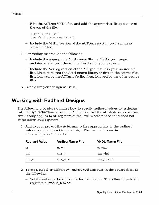
LO
Preface
6 Synplify User Guide, September 2004
– Edit the ACTgen VHDL file, and add the appropriate library clause at the top of the file:
library family ;use family.components.all
– Include the VHDL version of the ACTgen result in your synthesis source file list.
4. For Verilog macros, do the following:
– Include the appropriate Actel macro library file for your target architecture in your the source files list for your project.
– Include the Verilog version of the ACTgen result in your source file list. Make sure that the Actel macro library is first in the source files list, followed by the ACTgen Verilog files, followed by the other source files.
5. Synthesize your design as usual.
Working with Radhard DesignsThe following procedure outlines how to specify radhard values for a design with the syn_radhardlevel attribute. Remember that the attribute is not recur-sive. It only applies to all registers at the level where it is set and does not affect lower-level registers.
1. Add to your project the Actel macro files appropriate to the radhard values you plan to set in the design. The macro files are in <install_dir>/lib/actel:
2. To set a global or default syn_radhardlevel attribute in the source files, do the following:
– Set the value in the source file for the module. The following sets all registers of module_b to cc:
Radhard Value Verilog Macro File VHDL Macro File
cc cc.v cc.vhd
tmr tmr.v tmr.vhd
tmr_cc tmr_cc.v tmr_cc.vhd
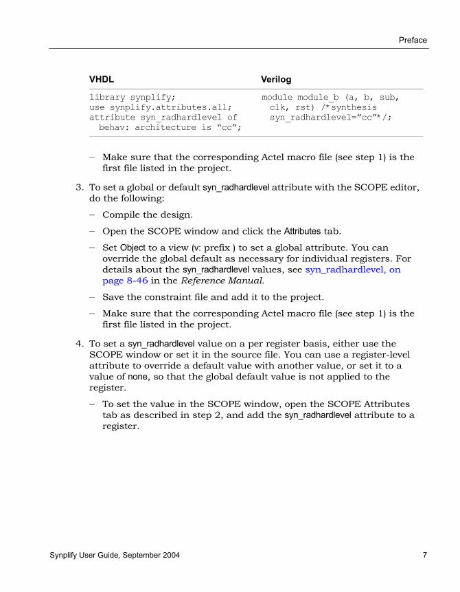
Preface
Synplify User Guide, September 2004 7
– Make sure that the corresponding Actel macro file (see step 1) is the first file listed in the project.
3. To set a global or default syn_radhardlevel attribute with the SCOPE editor, do the following:
– Compile the design.
– Open the SCOPE window and click the Attributes tab.
– Set Object to a view (v: prefix ) to set a global attribute. You can override the global default as necessary for individual registers. For details about the syn_radhardlevel values, see syn_radhardlevel, on page 8-46 in the Reference Manual.
– Save the constraint file and add it to the project.
– Make sure that the corresponding Actel macro file (see step 1) is the first file listed in the project.
4. To set a syn_radhardlevel value on a per register basis, either use the SCOPE window or set it in the source file. You can use a register-level attribute to override a default value with another value, or set it to a value of none, so that the global default value is not applied to the register.
– To set the value in the SCOPE window, open the SCOPE Attributes tab as described in step 2, and add the syn_radhardlevel attribute to a register.
VHDL Verilog
library synplify;use synplify.attributes.all;attribute syn_radhardlevel ofbehav: architecture is “cc”;
module module_b (a, b, sub, clk, rst) /*synthesis syn_radhardlevel=”cc”*/;

LO
Preface
8 Synplify User Guide, September 2004
– To set the value in the source file, add the attribute to the register. For example, to set the value of register bl_int to tmr_cc, enter the following in the module source file:
VHDL Verilog
library synplify;use synplify.attributes.all;attribute syn_radhardlevel ofbl_int: signal is “tmr_cc”
reg [15:0] a1_int, b1_int /*synthesis syn_radhardlevel = ”tmr_cc”*/;
Synplify User Guide, September 2004 1
C H A P T E R 7
Design Flows and Process Optimization
This chapter covers topics that can help the advanced user improve produc-tivity and interoperability with other tools. It includes the following:
• Using Batch Mode, on page 7-2
• Working with Tcl Scripts and Commands, on page 7-4
• Integrating with Third-Party Software, on page 7-10
• Working with the Identify RTL Debugger, on page 7-16
LO
Preface
2 Synplify User Guide, September 2004
Using Batch ModeBatch mode is a command-line mode where you run scripts from the command line. You might want to set up multiple synthesis runs with a batch script. You can run in batch mode if you have a floating license, but not with a node-locked license.
Batch scripts are in Tcl format. For more information about Tcl syntax and commands, see Working with Tcl Scripts and Commands, on page 7-4 and the Synplify Reference Manual.
This section describes the following operations:
• Running Batch Mode on a Project File, next
• Running Batch Mode with a Tcl Script, on page 7-3
Running Batch Mode on a Project FileUse this procedure to run batch mode if you already have a project file set up.
1. Make sure you have a project file (.prj) set up with the implementation options. For more information about creating this Tcl file, see Creating a Tcl Synthesis Script, on page 7-5.
2. From a command prompt, go to the directory where the project files are located, and type the following:
synplify -batch project_file_name.prj
The software runs synthesis in batch mode. Use absolute path names or a variable instead of a relative path name.
3. If there are errors in the source files, check the standard output for messages. On UNIX systems, this is generally the monitor; on Windows systems, it is the sdout.log file.
4. After synthesis, check the result_file.srr log file for error messages about the run.
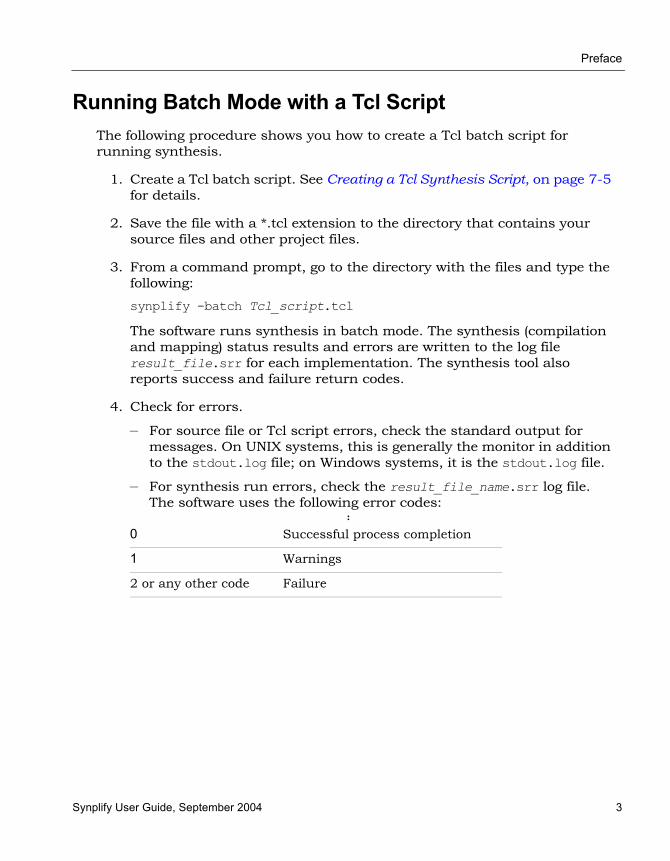
Preface
Synplify User Guide, September 2004 3
Running Batch Mode with a Tcl ScriptThe following procedure shows you how to create a Tcl batch script for running synthesis.
1. Create a Tcl batch script. See Creating a Tcl Synthesis Script, on page 7-5 for details.
2. Save the file with a *.tcl extension to the directory that contains your source files and other project files.
3. From a command prompt, go to the directory with the files and type the following:
synplify -batch Tcl_script.tcl
The software runs synthesis in batch mode. The synthesis (compilation and mapping) status results and errors are written to the log file result_file.srr for each implementation. The synthesis tool also reports success and failure return codes.
4. Check for errors.
– For source file or Tcl script errors, check the standard output for messages. On UNIX systems, this is generally the monitor in addition to the stdout.log file; on Windows systems, it is the stdout.log file.
– For synthesis run errors, check the result_file_name.srr log file. The software uses the following error codes:
:
0 Successful process completion
1 Warnings
2 or any other code Failure

LO
Preface
4 Synplify User Guide, September 2004
Working with Tcl Scripts and CommandsThe software uses extensions to the popular Tcl (Tool Command Language) scripting language to control synthesis and for constraint files. See the following for more information:
• Using Tcl Scripts, on page 7-4, next
• Generating a Job Script, on page 7-5
• Creating a Tcl Synthesis Script, on page 7-5
• Using Tcl Variables to Try Different Clock Frequencies, on page 7-7
• Using Tcl Variables to Try Several Target Technologies
• Running Bottom-up Synthesis with a Script, on page 7-9
Using Tcl Scripts1. To get help on Tcl syntax, do any of the following:
– Refer to the online help (Help -> Tcl Help) for general information about Tcl syntax.
– Refer to the Synplify Reference Manual for information about the synthesis commands.
2. To run a Tcl script, do the following:
– Create a Tcl script. Refer to Generating a Job Script, on page 7-5 and Creating a Tcl Synthesis Script, on page 7-5.
– Run the Tcl script by selecting File -> Run Tcl Script, selecting the Tcl file and clicking Open.
The software runs the selected script and executes the commands in it. For more information about Tcl scripts, refer to the following sections.

Preface
Synplify User Guide, September 2004 5
Generating a Job ScriptYou can record Tcl commands from the interface and use it to generate job scripts.
1. In the Tcl script window, type recording -file logfile to write out a Tcl log file.
2. Work through a synthesis session.
The software saves the commands from this session into a Tcl file that you can use as a job script, or as a starting point for creating other Tcl files.
Creating a Tcl Synthesis ScriptTcl scripts are text files with a *.tcl extension. You can use the graphic user interface to help you create a Tcl script. Interactive commands that you use actually execute Tcl commands, which are displayed in the Tcl window as they are run. You can copy this text in the Tcl window and paste it into a text file that you build to run as a Tcl script. For example:
add_file -verilog "prep2.v"set_option -technology PROASIC3set_option -part EP1SGX40Dset_option -package FC1020
project -run
The following procedure covers general guidelines for creating a synthesis script from scratch.
1. Use a text file editor or select File->New, click the Tcl Script option and type a name for your Tcl script.
2. Start the script by specifying the project with the project -new command. For an existing project, use load project.prj.
3. Add files. This may not be needed for an existing project.
– Add source files with add_file -vhdl or add_file -verilog. Make sure the top-level file is last:

LO
Preface
6 Synplify User Guide, September 2004
add_file -vhdl "statemach.vhd"add_file -vhdl "rotate.vhd"add_file -vhdl "memory.vhd"add_file -vhdl "top_level.vhd"
– Add constraint files with constraints and vendor-specific attributes. See Using a Text Editor for Constraint Files, on page 3-33 for details about this file.
add_file -constraint "design.sdc"
4. Set the design synthesis controls and the output:
– Set vendor-specific set_option controls as needed. See the appropriate vendor chapter in the Synplify Reference Manual for details.
set_option -technology VIRTEX2set_option -part XC2V40set_option -package CS144set_option -speed_grade -6
– Use the set_option command for implementation options.
set_option -symbolic_fsm_compiler trueset_option -frequency 30.0
– Set the output file information with project -result_file and project -log_file.
5. Set the file and run options:
– Save the project with project -save.
– Run the project with project -run.
– Open the RTL and Technology views:
open_file -rtl_viewopen_file -technology_view
6. Check the syntax.
– Check case, because Tcl is case-sensitive.
– Start all comments with a hash mark (#).
– Enclose all pathnames and filenames in double quotes.
– Always use a forward slash (/) in directory and pathnames, even on the PC.

Preface
Synplify User Guide, September 2004 7
Using Tcl Variables to Try Different Clock Frequencies To create a single script for multiple synthesis runs with different clock frequencies, you need to create a Tcl variable for the different settings you want to try. For example, you might want to try different target technologies.
1. To create a variable, use this syntax:
set variable_name {first_option_to_trysecond_option_to_try...}
2. Create a foreach loop that runs through each option in the list, using the appropriate Tcl commands. The following example shows a variable set up to synthesize a design with different frequencies. It also creates a separate log file for each run.
The following code shows the complete script:
project -load "design.prj"set try_these {
20.024.028.032.036.040.0
}
set try_freq {85.090.092.095.097.0100.0
)foreach frequency $try_freq {
set_option -frequency $frequencyproject -log_file $frequency.srrproject -run}
Tcl commands that set the frequency, create separate log files for each run, and run synthesis
Foreach loop
Set of frequenciesto try

LO
Preface
8 Synplify User Guide, September 2004
foreach frequency $try_these {set_option -frequency $frequencyproject -log_file $frequency.srrproject -runopen_file -edit_file $frequency.srr
}
Using Tcl Variables to Try Several Target Technologies This technique used here to run multiple synthesis implementations with different target technologies is similar to the one described in Using Tcl Variables to Try Different Clock Frequencies, on page 7-7. As in that section, you use a variable to define the target technologies you want to try.
1. Create a variable called try_these with a list of the technologies.
set try_these {
ISPGDX APEX20K Virtex2 # list of technologies}
2. Add a foreach loop that creates a new implementation for each technology and opens the RTL view for each implementation.
foreach technology $try_these {impl -addset_option -technology $technologyproject -run -fgopen_file -rtl_view
}
The following code example shows the script:
# Open a new project, set frequency, and add files.project -newset_option -frequency 33.3add_file -verilog "D:/test/simpletest/prep2_2.v"
# Create the Tcl variable to try different target technologies.set try_these
ISPGDX APEX20K Virtex2 # list of technologies}

Preface
Synplify User Guide, September 2004 9
# Loop through synthesis for each target technology.foreach technology $try_these {
impl -addset_option -technology $technologyproject -run -fgopen_file -rtl_view
}
Running Bottom-up Synthesis with a ScriptTo run bottom-up synthesis, you create Tcl scripts for individual logic blocks, and a script for the top level that reads the other Tcl scripts.
1. Create a Tcl script for each logic block. The Tcl script must synthesize the block. See Creating a Tcl Synthesis Script, on page 7-5 for details.
2. Create a top-level script that reads the block scripts. Create the script with the with project -new command.
3. Add the top-level data:
– Add source files with add_file -vhdl or add_file -verilog.
– Add constraint files with add_file -constraint.
– Set the top-level options with set_option.
– Set the output file information with project -result_file and project -log_file.
– Save the project with project -save.
– Run the project with project -run.
4. Save the top-level script, and then run it using this syntax:
source “block_script.tcl”
When you run this, the entire design is synthesized, beginning with the lower-level logic blocks specified in the sourced files, and then the top level.
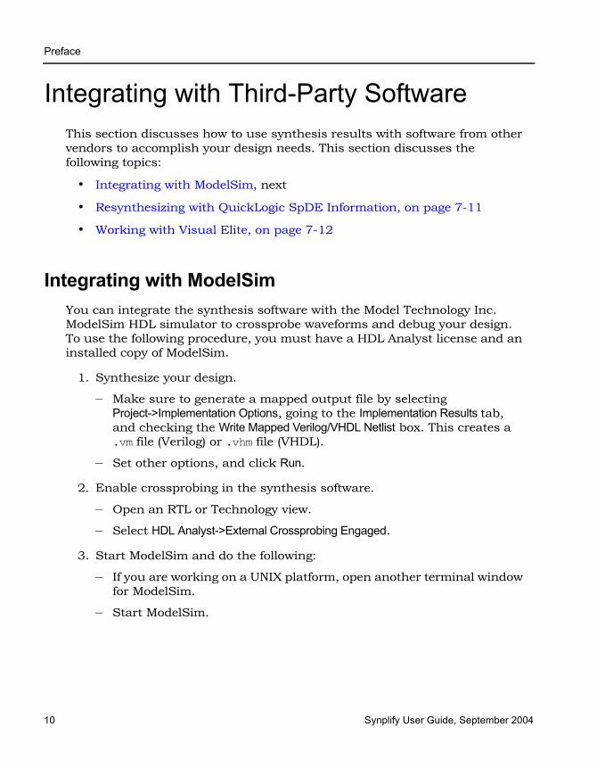
LO
Preface
10 Synplify User Guide, September 2004
Integrating with Third-Party SoftwareThis section discusses how to use synthesis results with software from other vendors to accomplish your design needs. This section discusses the following topics:
• Integrating with ModelSim, next
• Resynthesizing with QuickLogic SpDE Information, on page 7-11
• Working with Visual Elite, on page 7-12
Integrating with ModelSimYou can integrate the synthesis software with the Model Technology Inc. ModelSim HDL simulator to crossprobe waveforms and debug your design. To use the following procedure, you must have a HDL Analyst license and an installed copy of ModelSim.
1. Synthesize your design.
– Make sure to generate a mapped output file by selecting Project->Implementation Options, going to the Implementation Results tab, and checking the Write Mapped Verilog/VHDL Netlist box. This creates a .vm file (Verilog) or .vhm file (VHDL).
– Set other options, and click Run.
2. Enable crossprobing in the synthesis software.
– Open an RTL or Technology view.
– Select HDL Analyst->External Crossprobing Engaged.
3. Start ModelSim and do the following:
– If you are working on a UNIX platform, open another terminal window for ModelSim.
– Start ModelSim.
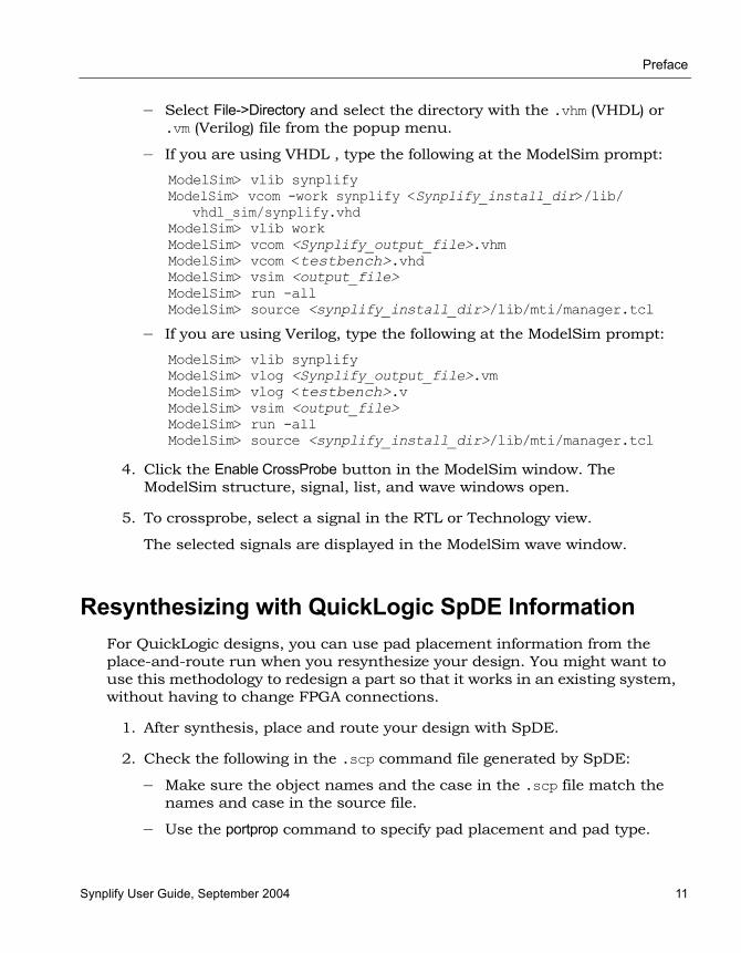
Preface
Synplify User Guide, September 2004 11
– Select File->Directory and select the directory with the .vhm (VHDL) or .vm (Verilog) file from the popup menu.
– If you are using VHDL , type the following at the ModelSim prompt:
ModelSim> vlib synplifyModelSim> vcom -work synplify <Synplify_install_dir>/lib/
vhdl_sim/synplify.vhdModelSim> vlib workModelSim> vcom <Synplify_output_file>.vhmModelSim> vcom <testbench>.vhdModelSim> vsim <output_file>ModelSim> run -allModelSim> source <synplify_install_dir>/lib/mti/manager.tcl
– If you are using Verilog, type the following at the ModelSim prompt:
ModelSim> vlib synplifyModelSim> vlog <Synplify_output_file>.vmModelSim> vlog <testbench>.vModelSim> vsim <output_file>ModelSim> run -allModelSim> source <synplify_install_dir>/lib/mti/manager.tcl
4. Click the Enable CrossProbe button in the ModelSim window. The ModelSim structure, signal, list, and wave windows open.
5. To crossprobe, select a signal in the RTL or Technology view.
The selected signals are displayed in the ModelSim wave window.
Resynthesizing with QuickLogic SpDE InformationFor QuickLogic designs, you can use pad placement information from the place-and-route run when you resynthesize your design. You might want to use this methodology to redesign a part so that it works in an existing system, without having to change FPGA connections.
1. After synthesis, place and route your design with SpDE.
2. Check the following in the .scp command file generated by SpDE:
– Make sure the object names and the case in the .scp file match the names and case in the source file.
– Use the portprop command to specify pad placement and pad type.

LO
Preface
12 Synplify User Guide, September 2004
– Specify fixed placement for I/O pads with the instprop command.
For the syntax of these commands, see the Synplify Reference Manual.
3. Include the .scp command file in your project by doing one of the following:
– Add the include directive to your project file, and specify the .scp file with the pad placement information.
– Add the include directive to a Tcl script file, and specify the .scp file with the pad placement information. Read the Tcl script into your project.
For more information about the include directive, see the Synplify Refer-ence Manual.
4. Resynthesize your design.
When you modify and resynthesize the design, the software keeps the pin locations specified in the included .scp file.
Working with Visual EliteVisual Elite™ is a third-party tool that you can use to create and edit HDL designs. For details about this tool, see http://www.sd.com/. You can crossprobe to this tool from the synthesis software, if you set it up correctly. This section covers the following:
• Windows Platform Setup, on page 7-12
• UNIX Platform Setup, on page 7-13
• Launching the Synthesis Software from Visual Elite, on page 7-14
• Crossprobing to the Visual Elite Editor, on page 7-14
Windows Platform SetupTo use Visual Elite and the Synplicity software together on the Microsoft® Windows® operating system, you need to do the following:
1. Ensure that Visual Elite is installed, with a valid license.

Preface
Synplify User Guide, September 2004 13
2. Set the following variables:
– Set the VSH_LIB environment variable to point to the directory:
synplify_installation_dir\lib\summit\visual
– Point the VSH_VISUAL_COMMAND environment variable to the executable:
Visual_Elite_installation_dir\bin\visual_elite.exe
– Set the LM_LICENSE_FILE environment variable to include the Synplicity license.
3. Set the path to include synplify_installation_dir\bin.
4. Edit the synplify.ini file and add the following lines:
[crossprobe]VisualEnabled = 1
5. Set Visual Elite options:
– Open Visual Elite, and select Tools->Options -> Synthesis -> Remote Synthesis, which opens a dialog box.
– In the dialog box, set Remote Synthesis to No.
– Set the directory in the Synthesis Directory text box. You can enter the path to any directory for which you have write permission. Click OK.
UNIX Platform SetupTo use Visual Elite and the Synplicity software together on a UNIX platform, you must do the following:
1. Make sure that the Visual Elite tool is properly installed on your system, with a valid license.
2. Set environment variables.
– Set the VSH_LIB to point to the Visual Elite directory:
synplify_installation_dir/lib/summit/visual
– Point the VSH_VISUAL_COMMAND environment variable to either the Verilog or VHDL version:
Visual_Elite_installation_dir/platform/bin/visual_elite
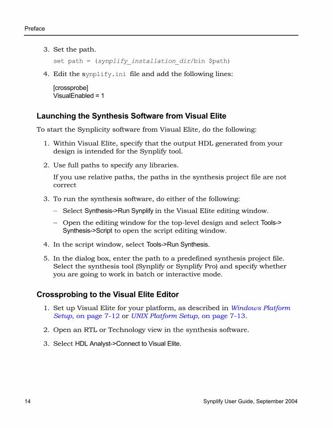
LO
Preface
14 Synplify User Guide, September 2004
3. Set the path.
set path = (synplify_installation_dir/bin $path)
4. Edit the synplify.ini file and add the following lines:
[crossprobe]VisualEnabled = 1
Launching the Synthesis Software from Visual EliteTo start the Synplicity software from Visual Elite, do the following:
1. Within Visual Elite, specify that the output HDL generated from your design is intended for the Synplify tool.
2. Use full paths to specify any libraries.
If you use relative paths, the paths in the synthesis project file are not correct
3. To run the synthesis software, do either of the following:
– Select Synthesis->Run Synplify in the Visual Elite editing window.
– Open the editing window for the top-level design and select Tools-> Synthesis->Script to open the script editing window.
4. In the script window, select Tools->Run Synthesis.
5. In the dialog box, enter the path to a predefined synthesis project file. Select the synthesis tool (Synplify or Synplify Pro) and specify whether you are going to work in batch or interactive mode.
Crossprobing to the Visual Elite Editor1. Set up Visual Elite for your platform, as described in Windows Platform
Setup, on page 7-12 or UNIX Platform Setup, on page 7-13.
2. Open an RTL or Technology view in the synthesis software.
3. Select HDL Analyst->Connect to Visual Elite.

Preface
Synplify User Guide, September 2004 15
4. Click or double-click the object in the HDL Analyst view.
Clicking Highlights the object in Visual Elite.
Double-clicking Highlights the object in Visual Elite and the associated HDL text in the Synplicity text editor window.

LO
Preface
16 Synplify User Guide, September 2004
Working with the Identify RTL DebuggerThe Identify® RTL debugger provides logic debugging capabilities that allow the designer to functionally debug the hardware directly in the RTL source code, in the target system, running at the target speed. This means the designer can functionally verify RTL designs thousands of times faster than with RTL simulators, and save results in the standard VCD format supported by most waveform viewers. This reduces the need for extensive system-level simulation, and simulation can concentrate on the much simpler and faster module-level simulation.
You can also use the Identify debugger in conjunction with the synthesis software to debug system-level functionality. You can add in-system stimuli for various applications in the Identify software, create a synthesis project, and debug the results graphically in the RTL view. The following procedure shows you how to launch the Identify RTL debugger from the synthesis inter-face and use it with the synthesis software to debug a design.
1. In the synthesis interface, open the design you want to debug, and then select Run->Launch Identify Instrumentor or select the icon ( ). If the icon and menu command are inaccessible, you are either on an unsupported platform (HP) or are using a technology that does not support this feature.
– If the synthesis application locates the Identify software, it opens a dialog box with the path to the Identify instrumentor executable. Set License Type to the appropriate technology, and click OK.
– If you have the Identify software installed but the synthesis application can not find it, click Locate in the dialog box that opens.
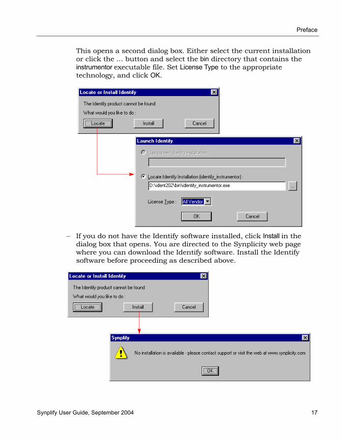
Preface
Synplify User Guide, September 2004 17
This opens a second dialog box. Either select the current installation or click the ... button and select the bin directory that contains the instrumentor executable file. Set License Type to the appropriate technology, and click OK.
– If you do not have the Identify software installed, click Install in the dialog box that opens. You are directed to the Synplicity web page where you can download the Identify software. Install the Identify software before proceeding as described above.
LO
Preface
18 Synplify User Guide, September 2004
The Identify software interface opens, with an Identify project automati-cally set up for the design to be debugged.
2. Do the following in the Identify interface:
– Open the RTL files, and instrument the design. For details of using the Identify instrumentor, refer to the Identify documentation.
– Save the instrumented design.
The Identify tool exports the instrumented design to the synthesis software. It creates an instrumentation subdirectory under your synthesis working directory called designName_instr, which contains the following:
– A synthesis project file
– An instr_sources subdirectory for the instrumented HDL files
– Tcl scripts for loading the instrumented design
3. Return to the synthesis interface and view the instrumented design that contains the debugging logic.
– In the synthesis interface, open the project file for the instrumented design, which is in theinstr_sources subdirectory listed in the Implementations Results view for your original synthesis project.
– Synthesize the design.
– Open the RTL view to see the inserted debugging logic.
4. Place and route the instrumented design after synthesis.
5. Return to the Identify interface and use the Identify debugger to debug the instrumented design. You do not have access to the Identify debugger with the evaluation copy; you must have a full-up version of Identify.

Synplify User Guide, September 2004 Index-1
Index
Symbols.ini file
adding crossprobing information for Visual Elite 7-13, 7-14
.sdc file 3-15
.v files. See Verilog
.vhd files. See VHDL
AActel
ACTgen macros 6-5macro libraries 6-5output netlist 6-4pin numbers for bus ports 6-3
ACTgen macros 6-5alspin
bus port pin numbers 6-3pin locations 6-2
alspreserveusing with syn_keep 5-11
Alt keycolumn editing 2-6
Alt key mapping 4-42area, optimizing 5-3asterisk wildcard
Find command 4-35async load warning message 4-4attributes
adding 3-36from RTL and Technology views 3-40in constraint files 3-35in SCOPE 3-38Verilog 3-37VHDL 3-36
for FSMs 5-15syn_encoding 5-15VHDL package 3-36
audience for the document 1-6
BB.E.S.T 4-13Back button
navigating views 4-20backslash
escaping dot wildcard in Find command 4-35
batch mode 7-2Behavior Extraction Synthesis Technology.
See B.E.S.Tblack boxes 5-22
adding constraints 5-26adding constraints in SCOPE 5-29adding constraints in Verilog 5-28adding constraints in VHDL 5-27instantiating in Verilog 5-22instantiating in VHDL 5-24pin attributes 5-30timing constraints 5-26
bookmarksin source files 2-6using in log files 4-3
browsers 4-24buffering
crontrolling 5-9bus
drag and drop 3-16
Cclock constraints
edge-to-edge delay 3-21false paths 3-27
clock constraints, setting 3-21clock domains
setting up 3-25clock groups
effect on false path constraints 3-27for global frequency clocks 3-22
clock trees 4-61

Index
Index-2 Synplify User Guide, September 2004
clocksasymmetrical 3-23defining 3-22frequency 3-23gated 3-25implicit false path 3-27limited resources 3-25overriding false paths 3-28
colorsin text files 2-10
column editing 2-6comment characters
in text files 2-10comments in source files 2-6compiler directives (Verilog)
specifying 3-10constraint files 3-31
See also SCOPEcolors 2-10comments 2-10creating in a text editor 3-33creating with SCOPE 3-13Find command 3-24fonts 2-10opening 3-15tabs 2-10when to use 3-31
constraintsadding in Tcl files 3-33black box 5-26defaults 3-18define_clock 3-34define_reg_input_delay 3-34kinds of 3-15options 3-5setting 3-16syn_reference_clock 3-34
contextfor object in filtered view 4-47
critical pathsdelay 4-63flat view 4-62hierarchical view 4-62slack time 4-63using -route 5-4viewing 4-62
crossprobing 4-38allowing to place-and-route file 4-20filtering text objects for 4-43from log file 4-3
from text files 4-42Hierarchy Browser 4-39ModelSim 7-10paths 4-42RTL view 4-40Technology view 4-40Text Editor view 4-40text file example 4-42Verilog file 4-40VHDL file 4-40with Visual Elite 7-14within RTL and Technology views 4-39
current levelexpanding logic from net 4-52expanding logic from pin 4-51
current level and below search 4-32current level search 4-32
Ddefault enum encoding 3-11define_attribute 3-40define_clock constraint 3-34define_false_paths constraint 3-34define_input_delay constraint 3-34define_multicycle_path constraint 3-34define_output_delay constraint 3-34define_reg_input_delay constraint 3-34define_reg_output_delay constraint 3-34design entry 1-4design flows
FPGA 1-4Synplify 1-12synthesis 1-12
design guidelines 5-2design hierarchy
viewing 4-44design size
amount displayed on a sheet 4-21device options
See alsoimplementation optionsdirectives
adding 3-36Verilog 3-37VHDL 3-36
black box 5-27, 5-28for FSMs 5-15specifying for the compiler (Verilog) 3-10syn_state_machine 5-20
Index
Synplify User Guide, September 2004 Index-3
syn_tco 5-28adding black box constraints 5-27
syn_tpd 5-28adding black box constraints 5-27
syn_tsu 5-28adding black box constraints 5-27
Dissolve Instances commandusing 4-58
dissolving 4-58dot wildcard
Find command 4-35drag and drop 3-16drivers
preserving duplicates with syn_keep 5-11
selecting 4-54
EEdit menu commands
for editing source files 2-5Editing window 2-5emacs text editor 2-8encoding styles
default VHDL 3-12FSM Compiler 5-18
errorsdefinition 2-4source files 2-4Verilog 2-4VHDL 2-4
Expand commandusing 4-51
Expand commandsconnections 4-54pin and net logic 4-50
Expand Inwards commandusing 4-51
Expand Paths commanddifferent from Isolate Paths 4-54
Expand to Register/Port commandusing 4-51
expandingconnections 4-54pin and net logic 4-50
Extract Generic Constants 3-11
Ffalse paths
defining between clocks 3-27I/O paths 3-28impact of clock group assignments 3-27overriding 3-28ports 3-27registers 3-27setting constraints 3-27
fanoutsbuffering vs replication 5-9hard limits 5-8soft global limit 5-7soft module-level limit 5-7using syn_maxfan 5-7
features 1-2files
.sdc 3-15
.v 2-2
.vhd 2-2fsm.info 5-19log 4-2output 6-4rom.info 4-27Tcl 7-4
See also Tcl commandsTcl batch script 7-3
Filter Schematic commandusing 4-49
Filter Schematic iconusing 4-49
filtering 4-48advantages over flattening 4-48using to restrict search 4-32
Find command4-32
browsing with 4-31constraint file 3-24hierarchical search 4-33long names 4-31reading long names 4-34search scope, effect of 4-35search scope, setting 4-33setting limit for results 4-34using in RTL and Technology views 4-32using wildcards 4-35wildcard examples 4-37
finding informationinformation organization 1-10
Flatten Current Schematic commandtransparent instances 4-56using 4-56
Index
Index-4 Synplify User Guide, September 2004
Flatten Schematic commandusing 4-56
flattening 4-56See also dissolvingcompared to filtering 4-48hidden instances 4-57transparent instances 4-56using syn_hier 5-10
fontssetting in text files 2-10
Forward buttonnavigating views 4-20
FPGA configuration 1-6FPGA design flow 1-4frequency
clocks 3-23internal clocks 3-24other signals 3-24
FSM Compiler 5-17advantages 5-17enabling 5-18
FSM encodinguser-defined 5-16using syn_enum_encoding 5-16
fsm.info file 5-19FSMs
See also FSM Compiler, FSM Explorerattributes and directives 5-15defining in Verilog 5-13defining in VHDL 5-14definition 5-13optimizing with FSM Compiler 5-17
GGenerics (VHDL panel) 3-11global optimization options 3-5
HHDL Analyst
See also RTL view, Technology viewcritical paths 4-62crossprobing 4-38filtering schematics 4-48Push/Pop mode 4-27, 4-29traversing hierarchy with mouse
strokes 4-25traversing hierarchy with Push/Pop
mode 4-27
using 4-44HDL Analyst tool
deselecting objects 4-18selecting/deselecting objects 4-17
HDL file icon 2-2help
information organization 1-10hidden instances
consequences of saving 4-46flattening 4-57restricting search by hiding 4-32specifying 4-45status in other views 4-45
hierarchical designexpanding logic from nets 4-51expanding logic from pins 4-51
hierarchical instancesdissolving 4-58hiding. See hidden instances, Hide
Instances commandmultiple sheets for internal logic 4-47pin name display 4-49viewing internal logic 4-46
hierarchical objectspushing into with mouse stroke 4-26traversing with Push/Pop mode 4-27
hierarchical search 4-32hierarchy
flattening 4-56traversing 4-24
hierarchy browserclock trees 4-61controlling display 4-20crossprobing from 4-39defined 4-24finding objects 4-30traversing hierarchy 4-24
history commands. See Back button, For-ward button.
II/O paths
false path constraint 3-28I/Os
Verilog black boxes 5-22VHDL black boxes 5-24
Identifyflow 7-16

Index
Synplify User Guide, September 2004 Index-5
running from the synthesis software 7-16
implementation options 3-2constraint 3-5device 3-2global optimization 3-5part selection 3-2specifying results 3-6
input constraints, setting 3-26input files. See source filesinstances
preserving with syn_noprune 5-11properties 4-14properties of pins 4-14
Isolate Paths commanddifferent from Expand Paths 4-54, 4-55
Kkeyboard shortcuts
Ctrl-d 3-17Ctrl-n 2-2Ctrl-s 2-3Ctrl-w 3-18Shift+F8 2-4shift-F7 2-4
keywords, completing in source files 2-6
Llatches
warning message 4-6license, setting up with the wizard 1-8LM_LICENSE_FILE environment variable
including synthesis in Visual Elite (Windows) 7-13
log fileschecking errors 2-4checking information 4-2colors 2-10fonts 2-10state machine descriptons 5-18tabs 2-10viewing 4-2
logicexpanding between objects 4-54expanding from net 4-51expanding from pin 4-51
logic preservationsyn_hier 5-12
syn_keep for nets 5-11syn_keep for registers 5-11syn_noprune 5-11syn_preserve 5-11
logic removalwarning message 4-8
Mmemory usage
maximizing with HDL Analyst 4-60ModelSim
working with 7-10mouse strokes
navigating between views 4-20pushing/popping objects 4-25
multicycle paths, setting constraints 3-21multisheet schematics 4-18
for nested internal logic 4-47searching just one sheet 4-32transparent instances 4-19
Nnetlists
for ModelSim 7-10netlists for different vendors 6-4nets
expanding logic from 4-51preserving with syn_keep 5-11properties 4-14selecting drivers 4-54
New property 4-16notes, definition 2-4
Oobjects
finding on current sheet 4-32flagging by property 4-15selecting/deselecting 4-17
optimizationfor area 5-3for timing 5-4logic preservation. See logic
preservation.preserving hierarchy 5-12preserving objects 5-10tips for 5-2
output constraints, setting 3-26

Index
Index-6 Synplify User Guide, September 2004
output files 6-4specifying 3-6
Ppackage library, adding 2-13part selection options 3-2path constraints
false paths 3-27pathnames
using wildcards for long names (Find) 4-34
pathstracing between objects 4-54tracing from net 4-51tracing from pin 4-51
paths, crossprobing 4-42PDF
cutting from 2-6pin names, displaying 4-50pins
expanding logic from 4-51properties 4-14
placement, description 1-5platform setup, Visual Elite GUI
UNIX 7-13ports
false path constraint 3-27properties 4-14
preferencescrossprobing to place-and-route
file 4-20displaying Hierarchy Browser 4-20displaying labels 4-21RTL and Technology views 4-20SCOPE 3-30sheet size (UI) 4-21
primitivespin name display 4-49pushing into with mouse stroke 4-26viewing internal hierarchy 4-44
probesusing Identify 7-16
project filesadding files 2-11adding files to 2-16batch mode 7-2creating 2-11definition 2-11deleting files from 2-16
opening 2-15replacing files in 2-16VHDL file order 2-13VHDL library 2-13
propertiesdisplaying with tooltip 4-14viewing for individual objects 4-14
Push/Pop modeHDL Analyst 4-25keyboard shortcut 4-27using 4-25, 4-27
Qquestion mark wildcard, Find command 4-35QuickLogic
pad placement 7-11
Rregister constraints, setting 3-21registers
false path constraint 3-27replication
controlling 5-9resource sharing
optimization technique 5-3overriding option with syn_sharing 5-6results example 5-6using 5-5
rom.info file 4-27ROMs
viewing data table 4-27routing, description 1-6RTL
debugging with Identify 7-16RTL view
adding attributes 3-40crossprobing description 4-38crossprobing from 4-40crossprobing from Text Editor 4-42defined 4-11description 4-10filtering 4-48finding objects with Find 4-32finding objects with Hierarchy
Browser 4-30flattening hierarchy 4-56icon 4-12opening 4-12

Index
Synplify User Guide, September 2004 Index-7
selecting/deselecting objects 4-17setting preferences 4-20state machine implementation 5-19traversing hierarchy 4-24
RTL view. See also HDL AnalystRTL views
analyzing clock trees 4-61
Sschematic objects
selecting/deselecting 4-17schematic page size 4-21schematics
multisheet. See multisheet schematicsselecting/deselecting objects 4-17
SCOPEadding attributes 3-38drag and drop 3-16setting constraints 3-13setting display preferences 3-30state machine attributes 5-15using the wizard 3-14using the wizard to generate
defaults 3-18scope of the document 1-7search
browsing objects with the Find command 4-31
browsing with the Hierarchy Browser 4-30
finding objects on current sheet 4-32setting limit for results 4-34setting scope 4-33using the Find command in HDL
Analyst views 4-32See also searchselection, in RTL and Technology views 4-17sensitivity list
warning message 4-7sentinel driver 1-9set_option command 3-4sheet connectors
navigating with 4-19sheet size
setting number of objects 4-21Show Cell Interior option 4-44Show Context command
different from Expand 4-47using 4-47
Show Critical Path icon 4-62slack
handling 4-65setting margins 4-62
Slow property 4-16source code
defining FSMs 5-13fixing errors 2-7opening automatically to
crossprobe 4-41optimizing 5-2when to use for constraints 3-31
source filesSee also Verilog, VHDL.adding comments 2-6adding files 2-11checking 2-4colors 2-10column editing 2-6comments 2-10copying examples from PDF 2-6creating 2-2crossprobing 4-42editing operations 2-5fonts 2-10specifying default encoding style 3-12specifying top level file in the
wizard 2-15specifying top level in Project view 2-13specifying top-level file in the
Implementation Options dialog box 3-12
state machine attributes 5-15tabs 2-10using bookmarks 2-6
specifying levels 4-58state machines
See also FSM Compiler, FSM Explorer, FSM viewer, FSMs.
attributes 5-15descriptions in log file 5-18implementation 5-19
syn_encoding attribute 5-15syn_enum_encoding directive
FSM encoding 5-16syn_hier attribute
controlling flattening 5-10preserving hierarchy 5-12
syn_isclockblack box clock pins 5-30

Index
Index-8 Synplify User Guide, September 2004
syn_keepusing with alspreserve 5-11
syn_keep attributeeffect on buffering 5-9preserving nets 5-11preserving shared registers 5-11
syn_maxfansetting fanout limits 5-7
syn_noarrayportsuse with alspin 6-3
syn_noprune attributepreserving instances 5-11
syn_preserveeffect on buffering 5-9
syn_preserve attributelogic removal warnings 4-8preserving FSMs from optimization 5-15preserving logic 5-11
syn_reference_clock constraint 3-34syn_replicate attribute
using buffering 5-9syn_sharing directive
overriding default 5-6syn_state_machine directive
using with value=0 5-20syn_tco attribute
adding in SCOPE 5-29syn_tco directive 5-28
adding black box constraints 5-27syn_tpd attribute
adding in SCOPE 5-29syn_tpd directive 5-28
adding black box constraints 5-27syn_tsu attribute
adding in SCOPE 5-29syn_tsu directive 5-28
adding black box constraints 5-27Synplify
starting from Visual Elite 7-14Synplify Pro
starting from Visual Elite 7-14Synplify software
design flow 1-12features 1-2overview 1-2starting 1-7
syntaxchecking source files 2-4checking Verilog 2-4
checking VHDL 2-4synthesis
checking source files 2-4checking Verilog 2-4checking VHDL 2-4
Synthesis On/Off Implemented as Translate On/Off 3-11
synthesis_on/off 3-11
Ttabs
setting in text files 2-10Tcl commands
batch script 7-3entering in SCOPE 3-22running 7-4
Tcl files 7-4adding constraints 3-33colors 2-10comments 2-10creating 7-5fonts 2-10for bottom-up synthesis 7-9guidelines 3-32naming conventions 3-32recording from commands 7-5tabs 2-10using variables 7-7wildcards 3-33
Tcl scriptsSee Tcl files.
technology mapping, description 1-5Technology view
See also HDL Analystadding attributes 3-40critical paths 4-62crossprobing 4-38, 4-40crossprobing from source file 4-42filtering 4-48finding objects with Find 4-32finding objects with Hierarchy
Browser 4-30flattening hierarchy 4-56general description 4-10opening 4-12selecting/deselecting objects 4-17setting preferences 4-20state machine implementation in 5-19traversing hierarchy 4-24
Index
Synplify User Guide, September 2004 Index-9
Text editorusing 2-5
text editorbuilt-in 2-5external 2-8
Text Editor viewcrossprobing 2-7, 4-40
Text Editor windowcolors 2-9fonts 2-9
text filescrossprobing 4-42
time stamp, checking on files 2-17timing constraints 3-34timing failures, handling 4-65timing information
critical paths 4-63timing optimization 5-4timing report
specifying format options 3-8tips
memory usage 4-60top level entity
specifying in VHDL 3-11top level module
specifying in VHDL 3-11transparent hierarchical instances
lower-level logic on multiple sheets 4-19transparent instances
flattening 4-56
UUNIX commands, synplify 1-7UNIX platform setup, Visual Elite GUI 7-13unused input, warning message 4-7
Vvendor-specific netlists 6-4Verilog‘ifdef and ‘define statements 3-10Actel ACTgen macros 6-6adding attributes and directives 3-37black boxes 5-22black boxes, instantiating 5-22checking 2-4choosing a compiler 3-9creating source files 2-2
crossprobing from HDL Analyst view 4-40
defining FSMs 5-13editing operations 2-5specifying compiler directives 3-10
Verilog 2001enabling globally 3-9setting global option from the Project
view 3-9setting option per file 3-9
Verilog macro librariesActel 6-5
VHDLActel ACTgen macros 6-5adding attributes and directives 3-36black boxes 5-24black boxes, instantiating 5-24checking 2-4creating source files 2-2crossprobing from HDL Analyst
view 4-40defining FSMs 5-14editing operations 2-5macro libraries, Actel 6-5
VHDL filesadding library 2-13adding third-party package library 2-13order in project file 2-13ordering automatically 2-13
vi text editor 2-8views
defined 4-20virtual clock, setting 3-21Visual Elite
crossprobing 7-14starting synthesis software from 7-14UNIX platform setup 7-13Windows platform setup 7-12
Visual Elite GUIUnix platform setup 7-13
VSH_LIB environment variableUNIX 7-13Windows 7-13
VSH_VISUAL_COMMAND environment variable 7-13
UNIX 7-13
Wwarning messages

Index
Index-10 Synplify User Guide, September 2004
async load 4-4definition 2-4latch generation 4-6logic removal 4-8sensitivity list 4-7unused input 4-7
warningsfeedback muxes 5-4handling 4-4
wildcardseffect of search scope 4-35Find command examples 4-37
wildcards (Find)how they work 4-35

Index
Synplify User Guide, September 2004 Index-11

Index
Index-12 Synplify User Guide, September 2004