synchronous design of avionic applications based on model
TRANSCRIPT

HAL Id: hal-00541523https://hal.archives-ouvertes.fr/hal-00541523
Submitted on 30 Nov 2010
HAL is a multi-disciplinary open accessarchive for the deposit and dissemination of sci-entific research documents, whether they are pub-lished or not. The documents may come fromteaching and research institutions in France orabroad, or from public or private research centers.
L’archive ouverte pluridisciplinaire HAL, estdestinée au dépôt et à la diffusion de documentsscientifiques de niveau recherche, publiés ou non,émanant des établissements d’enseignement et derecherche français ou étrangers, des laboratoirespublics ou privés.
Synchronous design of avionic applications based onmodel refinements
Abdoulaye Gamatié, Thierry Gautier, Paul Le Guernic
To cite this version:Abdoulaye Gamatié, Thierry Gautier, Paul Le Guernic. Synchronous design of avionic applicationsbased on model refinements. Journal of Embedded Computing (IOS Press), IOS Press, 2006, 2 (3-4),pp.273-289. <hal-00541523>

Synchronous Design of Avionic
Applications based on Model Refinement
Abdoulaye Gamatie∗†, Thierry Gautier‡and Paul Le Guernic§
Abstract
In this article, we address the design of avionic applications based
on an approach, which relies on model refinement. This study is done
within the synchronous framework, which has solid mathematical foun-
dations enabling formal methods for specification, verification and anal-
ysis, transformations, etc. In the proposed approach, we first consider
a functional description of a given application using the Signal lan-
guage. This description is independent of a specific implementation
platform. Then, some transformations that fully preserve the seman-
tics of manipulated Signal programs are applied to the description
such that a representation reflecting an integrated modular avionics
architecture results.
Keywords: Integrated Modular Avionics, ARINC, synchronous design, Sig-
nal, model refinement.
∗Corresponding author. Phone: +33 3 59 57 78 16; Fax: +33 3 28 77 85 38; E-mail:
[email protected]†Inria Futurs, Synergie Park, 6bis avenue Pierre et Marie Curie, 59260 Lezennes
‡Irisa, Campus de Beaulieu, 35042 Rennes, France. Email: [email protected]
§Irisa, Campus de Beaulieu, 35042 Rennes, France. Email: [email protected]
1

1 Introduction
Avionics play an important role in the overall cost of modern aircrafts (e.g.,
in civil aeronautics, it is estimated around 35% of the global cost). By avion-
ics, we mean electronic systems, equipment, and other devices aboard air-
crafts, which achieve functions like the treatment of information received
from sensors, the autopilot, the management of fuel level, communication
with an operator during a flight, etc. Today, we notice that avionics have
significantly evolved. In particular, the following observations can be made
about modern avionics [31] [34] [15]:
• functionalities are increasing in these systems: maintenance and on-
board diagnostic, mission simulation, need of autonomy, etc. On the
other hand, the integration level of functions is getting higher for an
efficient cooperation;
• contrarily to the traditional approach where functions are loosely cou-
pled (e.g., the autopilot and navigation functions are achieved by ap-
plications using different computing resources), avionics progressively
adopt an integrated approach, where functions (even of different criti-
cality levels) can be achieved through applications that share common
computing resources;
• the industry of avionics tends to use more and more commercial ma-
terial components, which are not a priori designed for these systems.
While this could help to reduce the development cost and increase
functionalities, there is the risk of guarantee lack of such products (as
2

a matter of fact, they rapidly become obsolete or unavailable);
• the correctness and reliability requirements call for the use of formal
methods in order to efficiently cope with validation problems.
Therefore, the increasing complexity and high criticality of embedded
real-time systems in the avionic domain raise some challenging issues about
their development. Among these issues, we mention the correctness of de-
signed systems against requirements, development effort, correctness and
reliability of implementations (e.g. the costs of minor and major bugs re-
spectively range from $100K to $500K and from $1M to $500M), time-to-
market (which is between three and four years). Therefore, there is the need
of suitable methodologies that efficiently address above issues. According to
Pnueli [32], such methodologies must enable at least formal specifications,
verification and analysis, and automatic (possibly distributed) code genera-
tion.
In this article, we address the design of avionic applications based on
model refinement within the development environment Polychrony, as-
sociated with the synchronous language Signal. Synchronous technologies
are interesting because of their formal basis, which favors validation. The
remainder of the article is organized as follows: Section 2 first introduces
avionics architectures: federated architectures and integrated modular avion-
ics - IMA (our study relies on the latter); then, Section 3 presents related
work; after a short introduction to the Signal language in Section 4, we ex-
pose our approach to describe IMA applications using the Signal language
in Section 5 and 6; finally, concluding remarks are given in Section 7.
3

2 Architecture design for avionics
We present the two basic approaches for architecture design in the avionic
domain: the federated approach (Section 2.1) and the integrated modular
approach (Section 2.2).
2.1 Federated architectures
Traditionally in avionics, each control function is associated with its own
material resources (e.g. computer system). These resources are most often
replicated for fault tolerance and they vary from one function to another.
Hence, it results a loosely-coupled and heterogeneous architecture where
every function can be almost executed independently of other functions. It
is not the case locally to a function, where concerned components strongly
cooperate in order to achieve the mission affected to that function. Such
an architecture of avionics is called federated architecture [3]. For instance,
the Airbus A330 and A340 adopt this kind of architecture. The numeric
equipments that implement the concerned on-board functions are linked by
a mono-emitter bus.
Besides their simplicity, a great advantage of federated architectures is
the minimization of the risk for error propagation, which can occur during
the execution of a function in the system. Another advantage of these ar-
chitectures is their inherent heterogeneity (computing resources required by
one function may differ from those needed by another). As a result, this
enables to use computer systems with variable performance characteristics
depending on functions.
4

However, a major drawback of federated architectures lies in the high
risk of massive usage of computing resources (replicated for fault tolerance)
since each function requires its dedicated computer system. Consequently,
the overall design costs get increased: enough space is required on-board
aircrafts in order to support the computing resources (typically, their asso-
ciated weight), one must cope with the resulting install and maintenance
issues, etc.
2.2 Integrated modular avionics (IMA)
More recently, another vision emerged concerning avionics design. This vi-
sion aims at dealing with the major obstacles inherent to federated archi-
tectures by proposing a system organization where several functions (even
of different criticality level) can share now computing and communication
resources. This new architecture is referred to as integrated modular avionics
(IMA) [3]. The Airbus A380 and Boeing B777 are examples of aircrafts that
adopt this kind of architecture.
IMA enables resource savings, thus reasonably limits the global develop-
ment costs. However, it may introduce a high error propagation probability,
which no longer exists in federated architectures (e.g., an abnormal execut-
ing application that achieves some function in the system may monopolize
the communication system or may provoke inappropriate commands; it is
not easy to preserve each function from such an erroneous behavior). The
solution that has been proposed in order to solve this problem consists in a
functional decomposition of the system, which takes into account the avail-
able memory space and time budget. The logical allocation unit resulting
5

from the decomposition is called a partition [3]. In practice, the spatial par-
titioning of systems relies on the use of material components in charge of
memory management, in order to prevent every memory area from corrup-
tion during modifications of its neighbored areas. The temporal partitioning
rather depends on expected system functionalities (e.g., it is crucial to exe-
cute regularly the function achieving the refreshment of critical parameters
such as the fuel level). Finally, we can notice that partitioning facilitates the
verification, validation and certification of avionics.
High-level IMA infrastructures. IMA platforms consist of core process-
ing modules (CPM) grouped in cabinets throughout the aircraft. Message
exchanges between cabinets is achieved through multiplex networks, which
are composed of buses (e.g. of ARINC 629 type [1] ) or Ethernet strands
linked by commutators. The IMA communication networks interacts with
its external environment (e.g. sensors and actuators) via gateway modules
(GWMs). Fig. 1 and 2 respectively illustrate two kinds of IMA infrastruc-
tures [9]. The first one shows an architecture for the Boeing B777 (CPMs
exchange messages within cabinets via ARINC 659 buses [2]) while the sec-
ond one depicts an architecture for the Airbus 380 (here, CPMs communicate
via an Ethernet network switched at nodes SW).
Module level. A core processing module contains one or more partitions
that possibly belong to functions of different criticality levels. Mechanisms
are provided in order to prevent a partition from having “abnormal” access
to the memory area of another partition. A processor is allocated to each par-
6

tition for a fixed time window within a major time frame maintained by the
module-level operating system (OS). A partition cannot be distributed over
multiple processors either in the same module or in different modules. Fi-
nally, partitions communicate asynchronously via logical ports and channels.
Message exchanges rely on two transfer modes: sampling mode and queuing
mode. In the former, no message queue is allowed. A message remains in
the source port until it is transmitted via the channel or it is overwritten by
a new occurrence of the message. A received message remains in the desti-
nation port until it is overwritten. A refresh period attribute is associated
with each sampling port. When reading a port, a validity parameter indi-
cates whether the age of the read message is consistent with the required
refresh period attribute of the port. In the queuing mode, ports are allowed
to store messages from a source partition in queues until they are received
by the destination partition (the queuing discipline is First-In First-Out).
Partition level. Partitions are composed of processes that represent exec-
utive units (in fact, an IMA partition/process is akin a UNIX process/task).
Processes run concurrently and achieve the functions associated with their
containing partitions. Each process is uniquely characterized by information
(typically, its period, priority or deadline time) useful to the partition-level
OS, which is responsible for the correct execution of processes within a
partition. The scheduling policy for processes is priority preemptive. Com-
munications between processes are achieved by three basic mechanisms. The
bounded buffer allows to send and receive messages following a FIFO policy.
The event permits the application to notify processes of the occurrence of
7

a condition for which they may be waiting. The blackboard is used to dis-
play and read messages: no message queues are allowed, and any message
written on a blackboard remains there until the message is either cleared or
overwritten by a new instance of the message. Synchronizations are achieved
using a semaphore.
The APEX-ARINC 653 standard [4] that codifies the “time/space par-
titioning” concept of IMA is now adopted by various real-time operating
systems, both proprietary and off-the-shelf (e.g. VxWorks AE653 ). It de-
fines an interface allowing IMA applications to access the underlying OS
functionalities. This interface includes services for communication between
partitions on the one hand and between processes on the other hand, syn-
chronization services for processes, and partition and process management
services, etc.
3 Related work
We first give a quick overview of works that specifically focus on IMA de-
sign. Then, we present three approaches aiming to address more general
issues on avionic software development: Aadl (Avionic Architecture De-
scription Language), Cotre (Real Time Components) and Scade (Safety
Critical Application Development Environment). All these approaches pro-
mote model-based and formal techniques. In particular, Scade relies on the
synchronous approach, which is also adopted in our study.
A few studies on IMA. We first mention studies that concern the two-
8

level hierarchical scheduling aspects of IMA systems. In [30] Lee et al. present
algorithms that provide cyclic partition and channel schedules for IMA sys-
tems. In the same context, Audsley and Wellings analyze response times of
IMA applications [7]. They point out the possibility of large amount of jitter
and discuss possible ways to reduce the jitter by checking process periods
with respect to partitions periods. In [23], we illustrate a Signal-based tech-
nique for temporal analysis that provides information about the execution
time of partitions. Typically, this information is useful when taking decisions
about processor allocation to partitions. Another benefit of defining such a
technique in a formal framework is the availability of techniques and tools
that help to address critical issues such as partitioning of IMA, which still re-
mains to be thoroughly explored. One outstanding study about partitioning
has been done by Di Vito [17]. He proposes a formal description of parti-
tioning requirements using the language associated with PVS (Prototype
Verification System). However, this description only concerns space parti-
tioning and does not address time partitioning. Communication is another
important topic in IMA systems. For this, we merely mention a communi-
cation network designed for the Airbus A380 presented by Sanchez-Puebla
and Carretero in [35]. Finally, a study addressing certification issues is done
by Conmy and McDermid [16] in which they propose a high level failure
analysis for IMA that is part of an overall IMA certification strategy.
AADL. The Avionics Architecture Description Language is a standard de-
veloped by the international Society of Automotive Engineers (SAE) [19].
It is dedicated to the design of the software and hardware components of
9

avionics and interfaces between these components. The definition of Aadl is
based on MetaH, an Architecture Description Language (Adl) developed
by Honeywell [36]. Aadl permits the description of the structure of an em-
bedded system as an assembly of software and hardware components in a
similar way as in MetaH. It also includes a dedicated Uml profile. This
enables the access to its underlying analysis and code generation tools from
Uml graphical specifications. While Aadl combines various formalisms and
tools for the design of embedded real-time systems, our approach relies on
the single semantic model of the Signal language. This favors a uniform
framework, which facilitates system validation.
COTRE. The Cotre approach [13] is also devoted to the design of em-
bedded real-time systems in the avionic domain. Its main objective consists
in providing the designer with a methodology, an Adl called Cotre and an
environment to describe, verify and implement embedded real-time systems.
The Cotre language distinguishes two different views for descriptions: a user
view expressed using the Cotre for User language (termed U-Cotre) and a
view for verification (termed V-Cotre). In fact, the latter plays the role of an
intermediate language between U-Cotre and existing verification formalisms
(e.g. timed automata, timed Petri nets). Authors of [13] argue that the use
of formal techniques is one of the main differences between the Cotre lan-
guage and other Adls. Cotre is closely related to Aadl.
SCADE. Scade proposes one of the most popular formal design envi-
ronments in avionics domain [18] [14]. It supports correct by construction
10

methodology [5] and automated generation of implementation from a high-
level formal model of embedded applications (cf. Fig. 3). As a result, drastic
savings of the development and validation effort are enabled.
Basically, Scade provides developer with two kinds of formalism for
specification: graphical block diagrams - GBDs (familiar to control engineers)
and hierarchical safe state machines - SSMs (based on the Esterel lan-
guage [12] and the SyncCharts state machine [6]). The former is used for
continuous control while the latter is used for discrete control. In this con-
text, continuous control means sampling sensors at regular time intervals,
performing signal-processing computations on their values, and producing
values often using complex mathematical formulas. Discrete control means
modifying behavior according to events coming either from discrete sensors
and user inputs or from internal program events. GBDs and SSMs can be
combined in order to define descriptions including both continuous and dis-
crete aspects. Scade adopts the synchronous computation model [10], which
is a fully precise representation of the well-known cycle-based computation
model. Roughly speaking, the cycle-based computation model consists of
a loop where a program (or a system) repeatedly achieves the following
actions: first read inputs from the environment, then compute them, and
finally write corresponding outputs (which the environment is waiting for).
In particular, Scade is based on the Lustre [26] and Esterel languages.
Its associated compilers and verifiers can be used to check the consistency
of specifications (e.g. detection of missing definitions, coherence of produc-
tion/consumption rates of data), and to validate them with respect to system
requirements. Finally, documentation and embeddable code can be automat-
11

ically generated from specifications-level descriptions by the Scade qualifi-
able code generator (level A with respect to DO-178B guidelines). This is
a major advantage of Scade compared to other synchronous design tools.
Among important avionic projects in which the Scade suite has been used,
we can mention the Airbus A380 and Eurocopter.
4 An introduction to the Signal language
The underlying theory of the synchronous approach is that of discrete event
systems and automata theory. Time is logical : it is handled according to
partial order and simultaneity of observed events. Actual execution dura-
tions are considered as constraints to be checked during implementation
phase. Typical synchronous languages are Esterel [12], Lustre [26] and
Signal [11]. They mainly differ from each other by their programming style
(Esterel is imperative while Lustre and Signal are dataflow oriented).
However, joint efforts have been made to provide a common format [8] in
order to facilitate interoperability.
Signal [11] is a dataflow oriented language. It handles infinite sequences
of typed values that are implicitly indexed by discrete logical time and called
signals. At a given logical instant, a signal may be present (then it holds
a value of some type, e.g., boolean, integer, real, etc.) or absent. There
is a particular type of signal called event. A signal of this type always
carries the value true. The set of instants where a signal is present is called
its clock. Signals that have the same clock are said to be synchronous. A
Signal program also termed a “process” (see Fig. 4), is a system of equations
12
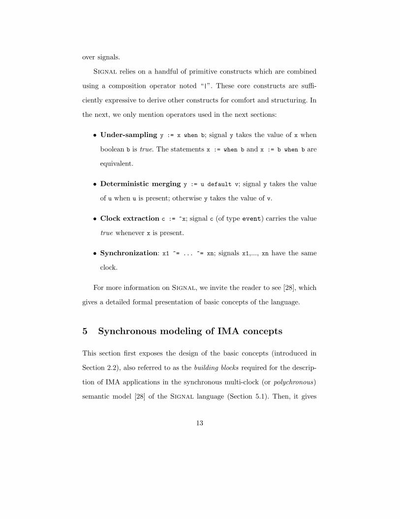
over signals.
Signal relies on a handful of primitive constructs which are combined
using a composition operator noted “|”. These core constructs are suffi-
ciently expressive to derive other constructs for comfort and structuring. In
the next, we only mention operators used in the next sections:
• Under-sampling y := x when b; signal y takes the value of x when
boolean b is true. The statements x := when b and x := b when b are
equivalent.
• Deterministic merging y := u default v; signal y takes the value
of u when u is present; otherwise y takes the value of v.
• Clock extraction c := ^x; signal c (of type event) carries the value
true whenever x is present.
• Synchronization: x1 ^= ... ^= xn; signals x1,..., xn have the same
clock.
For more information on Signal, we invite the reader to see [28], which
gives a detailed formal presentation of basic concepts of the language.
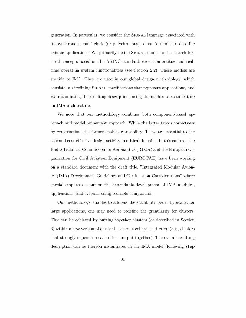
5 Synchronous modeling of IMA concepts
This section first exposes the design of the basic concepts (introduced in
Section 2.2), also referred to as the building blocks required for the descrip-
tion of IMA applications in the synchronous multi-clock (or polychronous)
semantic model [28] of the Signal language (Section 5.1). Then, it gives
13

a brief presentation of an ongoing work (see Section 5.2) that consists in
defining a modeling paradigm based on the resulting library of components
within a Generic Modeling Environment (Gme) [29]. The intent is to facil-
itate the access to the library together with the polychronous development
platform through very general modeling environments like Gme.
5.1 Basic building blocks
The synchronous design of avionic applications using Signal relies on a few
basic blocks [22], which allow us to model partitions: APEX-ARINC 653
services, an RTOS and executive entities (i.e. processes). In the following,
we show for each building block, how its corresponding Signal model is
obtained.
Modeling of APEX services. To illustrate the approach that has been
adopted here, let us consider a typical APEX service: the read blackboard
service [4]. It enables messages to be displayed and read in a blackboard.
The inputs are the blackboard identifier and a time-out duration that limits
the waiting time on a request, when the blackboard is empty. The outputs
are a message defined by its address and size, and a return code for the
diagnostics of the service request. An informal specification of the service is
given in [22].
We start by defining an abstract formal description that corresponds
to the service (see Fig. 4). This description expresses properties such as
logical instants at which a return code is produced (s.2). The variable
C_return_code is a local boolean signal with the value true whenever a
14

return code is received on a read request, i.e. C_return_code represents the
clock of the return code1 signal. For the moment, C_return_code appears
in the description as a local signal. It is defined during refinements of the
abstract description. At this stage, we assume that there only exist signals
such that properties in which it is involved are satisfied. Property (s.1)
states that C_return_code and all inputs are synchronous i.e. whenever
there is read request, C_return_code indicates whether or not a return
code is to be produced. Property (s.3) says that messages are received on
a read request only when the return code value is NO ERROR.
Lines (d.1) and (d.2) are dependency relations between inputs and
outputs. In Signal, the notation x --> y expresses a dependency relation
between two signals x and y within a logical instant (read: y is preceded
by x). For instance, (d.2) states that message and length are preceded by
timeout and board_ID, at the logical instants where the return code carries
the value NO_ERROR.
Descriptions such as the one in Fig. 4 are expressive enough to check, for
instance, the conformance of a component model during its integration into
a system described within the same formalism. Here, the description exhibits
the interface properties of the read blackboard service. More specifically, it
states conditions that describe when a message is received by a process on a
read request. However, the description does not mention how messages can
1The retrieval of a return code is not always immediate when calling the read blackboard
service. Typically, when the blackboard is empty and the timeout parameter carries some
positive value, the calling process is suspended. In this case, C return code carries the
value false. The suspended process must wait: either a message is displayed on the black-
board, or the expiration of the activated time counter, which produces the return code
TIMED OUT.
15

be obtained.
The specifications given in [4] are somewhat imprecise. This gives rise
to ambiguities, which are not easy to see. As an example we can think of
two possible implementations for the read blackboard service. They mainly
depend on the interpretation of message retrieval. Consider a process P1,
previously blocked on a read request in a blackboard and now released on a
display request by another process P2:
1. some implementations assume that the message read by the suspended
process P1 is the same as the one just displayed on the blackboard P2;
2. there are other implementations that display the message retrieved
by P1 when the execution of P1 is resumed. This is because a higher
priority process could be ready to execute when P1 gets released. So,
P1 does not necessarily read the message displayed by P2 since the
message may have been overwritten while it was suspended.
As one can notice, the level of detail of the model described in Fig. 4, al-
though somewhat abstract, allows to cover both interpretations of the ser-
vice. In practice, we observe that these interpretations can be useful depend-
ing on the context.
• Implementations of type (1) may be interesting when all the messages
displayed on the blackboard are relevant to the process P1. Every mes-
sage must be retrieved. However, even if using a blackboard for such
message exchanges appears cheaper than using a buffer (in terms of
memory space required for message queuing, and of blocked processes
16

management), it would be more judicious to consider a buffer for such
communications since it guarantees that no message is lost.
• On the other hand, implementations of type (2) are useful when P1
does not need to retrieve all displayed messages. For instance, P1 only
needs to read refreshed data of the same type. In that case, only the
latest occurrence of message is relevant.
The presence of ambiguities as illustrated above justifies a model refine-
ment design approach, where abstract descriptions are sufficiently general
and can be refined progressively in order to derive a particular implementa-
tion. Here, the way messages are retrieved during the read blackboard service
call is not clear. The model given in Fig. 4 allows to describe such a situation.
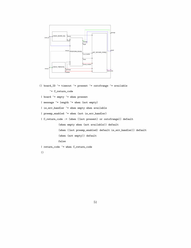
A more detailed version of the service model is shown in Fig. 5. This
model relies on the second interpretation of the read blackboard service. Its
internal properties can now be explicitly specified with respect to interface
properties defined in Fig. 4. For that, we start with a functional decom-
position of the informal specification of the service [22], and this leads to
four main sub-parts as illustrated in Fig. 5. Sub-parts CHECK_BOARD_ID and
CHECK_TIMEOUT verify the validity of inputs board_ID and timeout. If these
inputs are valid, PERFORM_READ tries to read the specified blackboard. Only
after this it sends the latest message displayed on the blackboard. It also
transmits all necessary information to GET_RETURN_CODE, which defines the
final diagnostic message of the service request. The intermediate signals ex-
changed by these sub-parts allow us to derive a complete definition of the
local signal C return code, which was only declared previously (see Fig. 4).
17

In addition, further properties such as clock relations between all identified
signals are specified. Finally, each sub-part is developed in a similar way so
as to define every signal. The resulting model of the service, which gives the
complete Signal code of the service can be found in [21].
The modeling of the other APEX-ARINC services follows the approach.
The corresponding models allow us to describe process management, com-
munication and synchronization between processes, etc. The next section
presents the definition of the partition-level OS, which is in charge of con-
trolling the execution of processes within a partition.
Modeling of the partition-level OS. The role of the partition level
OS is to ensure the correct concurrent execution of processes within the
partition; each process must have exclusive control on the processor. An
example model of the partition level OS is shown in Fig. 6.
The notions taken into account for the modeling of the partition level OS
are mainly: process management (e.g. create, suspend a process), scheduling
(including the definition of process descriptors and a scheduler), time man-
agement (e.g. update time counters), communications, and synchronizations
between processes. The APEX interface provides a major part of required
services to achieve the notions mentioned above. However, in order to have
a complete description of the partition level OS functionalities, we added
additional services to our library. These services allow us to describe process
scheduling within a partition and they also allow to update time counters.
Their description can be found in [22]. A case study using these services is
presented in [23]. Here, we only present the generic interface of the partition
18

level OS (cf. Fig. 6). We explain how it interacts with the other subparts of
its containing partition, in particular processes.
In Fig. 6, the input Active_partition_ID represents the identifier of the
running partition selected by the module-level OS, and it denotes an execu-
tion order when it identifies the current partition. The activation of all parti-
tions depends on this signal. It is produced by the module-level OS, which is
in charge of the management of partitions within a module. The presence of
the input signal initialize, which corresponds to the initialization phase
of the partition: creation of all the mechanisms and processes contained in
the partition. Whenever the partition executes, the PARTITION_LEVEL_OS
selects an active process within the partition. The process is identified by
the value carried by the output Active_process_ID, which is sent to each
process. The signal dt denotes duration information corresponding to pro-
cess execution. This is the duration of the current “block” of actions executed
by an active process. It is used to update time counter values. The signal
timedout produced by the partition-level OS carries information about the
current status of the time counters used within the partition. For instance, a
time counter is used for a wait when a process gets interrupted on a service
request with time-out. As the partition-level OS is responsible for the man-
agement of time counters, it notifies each interrupted process of the partition
with the expiration of its associated time counter. This is reflected by the
signal timedout.
Modeling of IMA processes. The definition of an IMA process model
consists of its computation and control parts. This is depicted in Fig. 7
19

with the sub-components CONTROL and COMPUTE. Any process is seen
as a reactive component that reacts whenever an execution order (denoted
by the input Active_process_ID) is received. The input timedout notifies
processes of time-out expiration. In addition, there are other inputs (respec-
tively outputs) needed for (respectively produced by) the process computa-
tions. The CONTROL and COMPUTE sub-components cooperate in order
to achieve the correct execution of the process model.
The CONTROL sub-component of the IMA process is a transition sys-
tem that indicates which statements have to be executed when the pro-
cess model reacts. It can be encoded quite naturally by an automaton in
Signal. A process executes whenever it is identified by the numeric input
Active_process_ID. Depending on the current state of the transition sys-
tem representing the execution flow of the process, a block of actions in the
COMPUTE sub-component is selected to be executed instantaneously (this
is represented by the arrow pointing from CONTROL to COMPUTE in the
figure). The COMPUTE sub-component is composed of blocks of actions
that represent elementary pieces of code to be executed without interrup-
tion. The statements associated with a block are assumed to complete within
a bounded amount of time. In the model, a block is executed instantaneously.
Therefore, one must take care of what kinds of statements can be put to-
gether in a block [20]. An execution of IMA process is a sequence of blocks,
and preemption occurs when there are two consecutive blocks that belong to
different processes in a sequence. Finally, the execution duration associated
with blocks is provided through dt. This information can be obtained before
or during the execution of the model using wcet calculation techniques [33]
20

or a profiling technique based on Signal [27], as illustrated in [23].
Global view of a partition model. Fig. 8 shows a coarse overview
of a partition composed of three processes. In this model, the component
GLOBAL_OBJECTS is created for structuring purposes. It mainly includes com-
munication and synchronization mechanisms used by the processes such as
buff, sema.
5.2 A modeling paradigm based on the building blocks
Now, we briefly discuss ongoing efforts in order to carry out our library
of components in the General Modeling Environment (Gme) [29]. The pri-
mary purpose is to increase the usability of the library by proposing the
same concepts within a non domain-specific tool such as Gme. Therefore,
without being an expert of synchronous technologies, a user could still be
able to design applications based on the IMA modeling approach proposed
in Polychrony. Today, we observe that the attention of the industry tends
to shift to frameworks based on general-purpose modeling formalisms (e.g.
the Unified Modeling Language), in response to a growing industry demand
for higher abstraction-levels in the system design process and an attempt to
fill the so-called productivity gap. This calls for an effort toward the con-
vergence between the theory of formal methods and the industrial practice
and trends in the design of embedded real-time systems.
Gme [29] is a configurable object-oriented toolkit, which supports the
creation of domain-specific modeling and program synthesis environments.
Metamodels are proposed in the environment to describe modeling paradigms
21

for specific domains: basic concepts required for model representation from
a syntactical viewpoint to a semantical one.
Our modeling paradigm for IMA design in Gme, called Mimad, is rep-
resented by the layer on the top in Fig. 9. The layers on the bottom are dedi-
cated to domain-specific technologies. Here, we consider the Polychrony en-
vironment, which is associated with the Signal language. However, one can
observe that the idea is extensible to further technologies that offer specific
useful functionalities to the Mimad layer (e. g., the integrated environment
Uppaal, which enables validation and verification of real-time systems using
timed automata). As Gme enables to import and export XML files, informa-
tion exchange between layers relies on this intermediate format. This favors
a high flexibility and interoperability.
The Mimad layer aims at providing a user with a graphical framework
allowing to model applications using a component-based approach. Applica-
tion architectures can be easily described by just selecting these components
via drag and drop. Component parameters (e.g. period or deadline of an IMA
process model) can be specified. The resulting Gme model is transformed in
Signal (referred to as Mimad2Sig in Fig. 9) based on the XML intermediate
format.
In the synchronous data-flow layer, the XML description obtained from
the upper layer is used to generate a corresponding Signal model of the
initial application description. This is achieved by using the IMA-based com-
ponents already defined in Polychrony [22]. Thereon, the formal analysis
and transformation techniques available in the platform can be applied to
the generated Signal specification. Finally, a feedback is sent to the Mi-
22

mad layer to notify the user with possible incoherences in initial descriptions.
By defining the Mimad layer, users can easily design applications based
on the IMA modeling approach proposed in Polychrony without being
experts of synchronous technologies.
In the next section, a methodology is proposed in order to generalize our
design approach for IMA applications in Signal. The key idea is to con-
sider initial Signal program representing an application. This program does
not reflect any implementation architecture. By applying some conservative
transformations (i.e. they strictly preserve the semantics of manipulated pro-
grams) to the program, we obtain a new program that can be instantiated
on the IMA architecture using our predefined building blocks.
6 Design by model refinement
By refinement, we mean a set of transformations allowing to define pro-
gressively, from an initial Signal description P, further descriptions in the
following way: at each step, a new description Q is obtained through the “in-
stantiation” of intermediate variables by adding supplementary equations to
P. Typically, this refinement process could modify non-functional properties
of P such as temporal properties, by introducing delays during the execution
or by relaxing some synchronization relations, but its functional properties
are strictly preserved.
23

6.1 Basic notions
The notions presented below have been introduced during the European
project Sacres [24]. Its goal was to define ways for generating distributed
code from synchronous specifications (particularly Signal programs). In
the following, an application is represented by a Signal program P =
P1 | P2 | ... | Pn, where each sub-program Pi can be itself recursively com-
posed of other sub-programs (i.e., Pi = Pi1 | Pi2 | ... | Pim). We assume the
following hypotheses:
1. considered programs P are initially endochronous [28], hence tem-
porally deterministic (roughly speaking, an endochronous program is
temporally insensitive to its environment behavior);
2. they do not contain any circular definitions;
3. a set of processors q = {q1, q2, ..., qm}; and
4. a function locate : {Pi} −→ P(q), which associates with each subpart
of an application P = P1 | P2 | ... | Pn a non empty set of processors
(the allocation can be done either manually or automatically).
First transformation. Let us consider a Signal program P = P1 | P2,
as illustrated in Fig. 10. Each sub-program Pi (represented by a circle) is
itself composed of four sub-programs Pi1, Pi2, Pi3 and Pi4. The program P
is distributed on two processors q1 and q2 as follows:
∀i ∈ {1, 2} ∀k ∈ {1, 2}, locate(Pik) = {q1} and
∀i ∈ {1, 2} ∀k ∈ {3, 4}, locate(Pik) = {q2}
24

Hence, P can be rewritten into P = Q1 | Q2, where
Q1 = P11 | P12 | P21 | P22 and
Q2 = P13 | P14 | P23 | P24
The sub-programs Q1 and Q2 resulting from the partitioning of P are
called s-tasks [24]. This transformation yields a new form of the program P
that reflects a multi-processor architecture. It also preserves the semantics
of the transformed program (since it simply consists of program rewriting).
Second transformation. We want to refine the level of granularity re-
sulting from the above transformation. For that we consider descriptions at
processor level, so called s-tasks. We are now interested in how to decom-
pose s-tasks into fine grain entities. An s-task can be seen as a set of nodes
(e.g. P11, P12, P21 and P22 in Q1). In order to get an optimized execution at
the s-task level, nodes are gathered in a way such that they can be executed
atomically. We therefore distinguish two possible ways to define such subsets
of nodes, also referred to as clusters: either they are composed of a single
Signal primitive construct, or they contain more than one primitive con-
struct. The former yields a finer granularity than the latter. However, from
the execution point of view, the latter is more efficient since more actions
can be achieved at a same time (i.e. atomically).
The definition of atomic nodes use the following criterion: all expressions
contained in a node depend on the same set of inputs. The verification of
this condition relies on a sensitivity analysis. There exists a causality path
25

between a node N1 and a node N2 if there is at least one situation where
the execution of N2 depends on the execution of N1. If this is the case, all
possible intermediate nodes are also scheduled to be executed.
Definition 1 Two nodes N1 and N2 are sensitively equivalent iff for each
input i: there is a causality path from i to N1 ⇔ there is a causality path
from i to N2.
Sensitively equivalent nodes belong to the same cluster. Inputs always
precede outputs within a cluster. Also, if a transformed program is initially
endochronous, the resulting clusters are also endochronous (this ensures a
deterministic execution of each cluster). Fig. 11 shows a decomposition of
the s-task Q1 into two clusters L1 and L2. The input of the sub-program
P11 (bold-faced arrow) is originally an input of P . The other arrows rep-
resent communications between s-tasks (These message exchanges are local
to P ). We can notice that after this second transformation, the semantic
equivalence of the initial program and the resulting one is strictly preserved.
The two transformations presented above describe a partitioning of Sig-
nal programs following a multi-task multi-processor architecture. The in-
stantiation of such a description in the IMA model consists in using the
ARINC component models we have introduced in Section 5.1 (APEX ser-
vices, processes, partitions).
26

6.2 Instantiation of Signal programs in the IMA model
We present this instantiation at processor level but the approach can be
generalized for the multi-processor level. From the above transformations,
a processor can be considered as a graph where nodes are represented by
clusters. Therefore, the partitioning of a given Signal program following
the IMA architecture model is obtained through the following steps :
• Step 0: Distribution on available processors. Here, we assume a
given distribution function. The program is transformed into s-tasks.
In practice, this step is often an expert matter. However, there exist
tools that can help to achieve this kind of task (e.g SynDEx [25]).
• Step 1: For each processor, transform the associated s-task
into a graph of clusters. This task is done automatically by the
Signal compiler.
• Step 2: For each processor, associate clusters with parti-
tions/processes. The first decision about the graph of clusters re-
sulting from the previous step consists in choosing a partitioning of
clusters into IMA partitions/processes. In other words, we have to
identify clusters that can be executed within the same partition/process.
In our simple example, we decide to model the graph associated with
Q1 (cf. Fig. 11) by one partition. Once partitions are chosen, each
graph corresponding to a partition is decomposed into sub-graphs.
These contain the clusters that should be executed by the same pro-
cess. In the example, clusters associated with the “partition Q1” form
27

the set of instruction blocks of a single process. The decomposition of
a graph of clusters into partitions and processes has to be done with
respect to coherent criteria. For instance, it can be very interesting
to put clusters that strongly depend on each other together in a same
partition/process. This would greatly reduce inter-process communica-
tion costs. In the next step, the program can be effectively instantiated
using our building blocks.
• Step 3: Instantiate the program in the IMA model. Two
phases are considered: we first instantiate processes then partitions.
An overview of used basic components is given in Fig. 12. The symbol
“|” denotes the synchronous composition. The following transforma-
tions are defined:
1. Description of the process associated with a set of clusters:
– The definition of the CONTROL part of the process relies
on dependencies between clusters. Clusters are executed se-
quentially with respect to these dependencies.
– Each cluster is “embedded” in a block within the COMPUTE
part of the process.
– Internal communications between the clusters of a sub-graph
associated with a process are modeled using local state vari-
ables (i.e. those defined by the delay primitive construct).
These variables enable to memorize exchanged data. On the
other hand, communications between sub-graphs of clusters
from different processes are modeled with APEX services. For
28

each entry point (resp. exit point) of a sub-graph, a block con-
taining a suitable communication or synchronization service
call is added in the COMPUTE part of the associated pro-
cess model. When the process becomes active, this block is
executed just before (resp. after) the block that contains the
cluster concerned by the entry point (resp. the exit point).
The choice of the suitable service to call here depends on the
desired type of communication. For instance, if one needs
to use a bounded message queue, services associated with a
buffer are preferred to those related to a blackboard, which
are more appropriate for message exchanges via one memory-
place. Services associated with semaphore are used for syn-
chronization.
2. Description of the partition associated with a set of clusters:
– The component corresponding to the partition-level OS (con-
taining among other things the scheduler, which manages
process execution within the partition) is added to processes
defined at the previous phase.
– The communication and synchronization mechanisms used
by the APEX services added in the previous phase are created
(for instance, for a send buffer service call, a buffer should
be created in which messages can be stored). This creation
is done for example within the GLOBAL OBJECTS sub-part of
the partition, as illustrated on Fig. 8.
29

Example Fig. 13 outlines a process model resulting from the transforma-
tion of Q1. There are six blocks two of which contain the clusters L1 and
L2. The other blocks have been added for communication: r, s and w re-
spectively denote a read request (receive buffer or read blackboard), an event
notification (set event), and an event notification waiting (wait event). The
automaton described in the control part gives the execution order of the blocks
with respect to the precedence constraints of the cluster graph. It is derived
following the identified dependencies. The corresponding partition is obtained
by considering the phase 2 of Step 3, in the current section.
For each processor with multiple partitions, a model of partition sched-
uler is required. Partition management is done based on a time sharing strat-
egy, so we have to compose a component (corresponding to the module-level
OS - see Section 2.2) with partition models. A model of such a component
is similar to the partition-level OS in that its definition relies on the use of
APEX services, except that the scheduling policy differs.
6.3 Discussion
One major characteristic of our study is the use of formal techniques in or-
der to address design obstacles in safety-critical domains such as avionics.
In the proposed solution, we advocate a correctness by construction philos-
ophy, which facilitates validation issues. As a result, global design costs can
be significantly reduced. More generally, we use the synchronous technology,
which provides designers with tools and techniques with solid mathematical
foundations for specification, verification and analysis, and automatic code
30
generation. In particular, we consider the Signal language associated with
its synchronous multi-clock (or polychronous) semantic model to describe
avionic applications. We primarily define Signal models of basic architec-
tural concepts based on the ARINC standard: execution entities and real-
time operating system functionalities (see Section 2.2). These models are
specific to IMA. They are used in our global design methodology, which
consists in i) refining Signal specifications that represent applications, and
ii) instantiating the resulting descriptions using the models so as to feature
an IMA architecture.
We note that our methodology combines both component-based ap-
proach and model refinement approach. While the latter favors correctness
by construction, the former enables re-usability. These are essential to the
safe and cost-effective design activity in critical domains. In this context, the
Radio Technical Commission for Aeronautics (RTCA) and the European Or-
ganization for Civil Aviation Equipment (EUROCAE) have been working
on a standard document with the draft title, ”Integrated Modular Avion-
ics (IMA) Development Guidelines and Certification Considerations” where
special emphasis is put on the dependable development of IMA modules,
applications, and systems using reusable components.
Our methodology enables to address the scalability issue. Typically, for
large applications, one may need to redefine the granularity for clusters.
This can be achieved by putting together clusters (as described in Section
6) within a new version of cluster based on a coherent criterion (e.g., clusters
that strongly depend on each other are put together). The overall resulting
description can be thereon instantiated in the IMA model (following step
31
3 in the methodology).
Another important issue is usability. Our methodology is entirely de-
veloped within Polychrony, the design environment associated with the
Signal language. This means that some knowledge of synchronous program-
ming is a prerequisite to use the provided models. However, as illustrated in
Section 5.2, we are currently modeling the same concepts within the Gme
environment, which is not a domain-specific tool. This supplementary layer
will be connected to Polychrony so as to provide users with access to our
Signal models.
Compared to existing related work, we can mention common points be-
tween our study and di Vito’s work [17] in that guaranteeing the correctness
of partitioning is a major objective. However, in [17], the author first con-
siders a given application partitioning and then addresses correctness issues.
Here, we rather use the data-flow representation offered by the Signal lan-
guage to get a correct-by-construction partitioning, based on the sensitivity
analysis. Akin to Cotre [13] and Aadl [19], our work aims at provid-
ing a solution to design and validation problems for avionic applications.
However, our approach entirely relies on the single semantic model of the
Signal language. This is not the case in Cotre and Aadl where different
kinds of formalism are considered for specification, verification, and analysis.
Using different formalisms can lead to difficult validation activity. Finally,
we mention the Scade approach [14], which is close to our approach. While
both rely on the synchronous technology, they do not have the same vision
of a system execution: the approach exposed in this article considers an
operating system based computation whereas Scade uses the cycle-based
32

computation model.
7 Conclusions
In this article, we present a design methodology based on model refinement
for avionic applications deployed on integrated modular avionics architec-
tures (IMA). This methodology relies, on the one hand, on systematic and
conservative transformations of Signal programs and, on the other hand,
on the use of a library of component models (also described in Signal)
specified by the avionic standard ARINC. For a given application, an asso-
ciated initial Signal specification is first considered, which is independent
of a specific implementation platform. This application is distributed on a
multi-processor architecture with the help of a specific distribution function.
Each resulting sub-part is now refined using transformations that strictly
preserve the semantics of the application. Finally, on each processor, our
ARINC component models are used to instantiate the transformed applica-
tion sub-parts such as to reflect IMA architecture.
Beyond the fact that our approach promotes a design activity within
a formal framework and therefore simplifies validation issues, it suggests
a solution to critical issues in partitioning of avionics. Indeed, the lack of
techniques that efficiently cope with these issues makes federated architec-
tures still very attractive from IMA ones. As a result, IMA architectures
and operating systems do not currently extend to the most critical avionic
functions. For instance, flight-critical systems such as the aircraft environ-
ment surveillance system (AESS) or the flight management system (FMS)
33

employ separate hardware assemblies and operating systems. The sensitiv-
ity analysis described in our approach provides a correct by construction
way enabling an easy identification of dependencies between sub-parts of an
application, which favors a reliable partitioning of the application.
Our methodology is defined within the Polychrony platform that offers
a set of tools and techniques for model transformation and analysis based
on the Signal language (http://www.irisa.fr/espresso/Polychrony).
A library of APEX-ARINC component models is available within the plat-
form.
Acknowledgments
This work has been partly supported by the European project IST SafeAir
(Advanced Design Tools for Aircraft Systems and Airborne Software - see
the following address: http://www.safeair.org).
References
[1] Airlines Electronic Engineering Committee. ARINC 629: IMA Multi-
transmitter databus parts 1-4. Technical Report 629, Aeronautical radio, Inc.,
Annapolis, Maryland, October 1990.
[2] Airlines Electronic Engineering Committee. ARINC 659: Backplane data bus.
Technical Report 659, Aeronautical radio, Inc., Annapolis, Maryland, Decem-
ber 1993.
34

[3] Airlines Electronic Engineering Committee. ARINC report 651-1: Design guid-
ance for integrated modular avionics. Technical Report 651, Aeronautical ra-
dio, Inc., Annapolis, Maryland, November 1997.
[4] Airlines Electronic Engineering Committee. ARINC specification 653: Avionics
application software standard interface. Technical Report 653, Aeronautical
radio, Inc., Annapolis, Maryland, January 1997.
[5] P. Amey. Correctness by construction: Better can also be cheaper. CrossTalk
Magazine, The journal of Defense Software Engineering, March 2002.
[6] C. Andre. Computing synccharts reactions. In Proc. of Synchronous Lang.,
Applications, and Programming (SLAP’03), Porto - Portugal, July 2003.
[7] N.C. Audsley and A.J. Wellings. Analysing APEX Applications. In Proceedings
of Real Time Systems Symposium (RTSS’96), Washington, DC, USA, IEEE
Computer Society, December 1996.
[8] P. Beaufreton, H. Granier, X. Mehaut, and E. Rutten. The Sacres approach
to embedded systems applied to aircraft engine controllers. In Proc. of the 22nd
IFAC/IFIP Workshop on Real-Time Program., Lyon - France, Sep. 1997.
[9] G. Bel, F. Boniol, G. Durrieu, C. Fraboul, J. Foisseau, and V. Wiels. Modeles
comportementaux pour l’avionique modulaire integree. In 1er Congres pluri-
sectoriel - Logiciel Temps Reel Embarques - Meteo France, Toulouse, pages
677–691, January 2002.
[10] A. Benveniste, P. Caspi, S. Edwards, N. Halbwachs, P. Le Guernic, and R. de
Simone. The synchronous languages twelve years later. Proceedings of the
IEEE, 91(1):64–83, January 2003.
[11] A. Benveniste, P. Le Guernic, and C. Jacquemot. Programming with events
and relations: the Signal language and its semantics. Science of Computer
Programming, 16(2):103–149, November 1991.
35

[12] G. Berry and G. Gonthier. The Esterel synchronous programming lan-
guage : design, semantics, implementation. Science of Computer Programming,
19(2):87–152, November 1992.
[13] B. Berthomieu et al. Towards the Verification of Real-Time Systems in Avion-
ics: the Cotre Approach. In 8th International workshop for industrial critical
systems, ROROS, Thomas Arts, Wan Fokkink (eds), pages 201–216, June 2003.
[14] J.-L. Camus and B. Dion. Efficient development of airborne soft-
ware with Scade suite. In Esterel Technologies white paper, 2003.
http://www.esterel-technologies.com.
[15] D. Cofer and M. Rangarajan. Formal modeling and analysis of advanced
scheduling features in an avionics RTOS. In procedings of Conference on
Embedded Software (EMSOFT’02), J. Sifakis and A. Sangiovanni-Vincentelli,
Eds, LNCS 2491, Springer Verlag, p. 138-152, 2002.
[16] P. Conmy and J. McDermid. High Level Failure Analysis for Integrated Mod-
ular Avionics. In Proceedings of the 6th Australian Workshop on Industrial
Experience with Safety Critical Systems and Software, Brisbane, Australia,
June 2001.
[17] B.L. Di Vito. A Model of Cooperative Noninterference for Integrated Modular
Avionics. In Proceedings of Dependable Computing for Critical Applications
(DCCA-7), San Jose, CA, January 1999.
[18] Esterel Technologies. Scade language reference manual. 2004.
http://www.esterel-technologies.com.
[19] P.H. Feiler, B. Lewis, and S. Vestal. The SAE Avionics Architecture De-
scription Language (Aadl) Standard: A Basis for Model-Based Architecture-
Driven Embedded Systems Engineering. In Proceedings of Workshop on Model-
Driven Embedded Systems, Washington D.C., USA, May 2003.
36

[20] A. Gamatie. Modelisation polychrone et evaluation de systemes temps reel.
PhD thesis, Universite de Rennes I, Rennes, France, May 2004.
[21] A. Gamatie and T. Gautier. Synchronous modeling of modular avionics archi-
tectures using the Signal language. Technical Report 4678, INRIA, December
2002. Available at http://www.inria.fr/rrrt/rr-4678.html.
[22] A. Gamatie and T. Gautier. Synchronous modeling of avionics applications
using the Signal language. In Proc. of the 9th IEEE Real-time/Embedded
technology and Applications symposium (RTAS’03). Washington D.C., USA,
May 2003.
[23] A. Gamatie, T. Gautier, and P. Le Guernic. An example of synchronous
design of embedded real-time systems based on IMA. In Proceedings of the
10th International Conference on Real-time and Embedded Computing Systems
and Applications (RTCSA’04). Gothenburg - Sweden, August 2004.
[24] T. Gautier and P. Le Guernic. Code generation in the Sacres project.
In Safety-critical Systems Symposium (SSS’99), Springer. Huntingdon, UK,
February 1999.
[25] T. Grandpierre and Y. Sorel. From algorithm and architecture specifications
to automatic generation of distributed real-time executives: a seamless flow of
graphs transformations. In Formal Methods and Models for Codesign Confer-
ence (MEMOCODE’03), Mont Saint-Michel, France, June 2003.
[26] N. Halbwachs, F. Lagnier, and C. Ratel. Programming and verifying real-
time systems by means of the synchronous data-flow programming language
Lustre. IEEE Trans. on Software Engineering, 18(9):785–793, Sep. 1992.
[27] A. Kountouris and P. Le Guernic. Profiling of Signal programs and its ap-
plication in the timing evaluation of design implementations. In IEE Colloq.
37

on HW-SW Cosynthesis for Reconfigurable Systems, IEE, pages 6/1–6/9. HP
Labs, Bristol, UK, February 1996.
[28] P. Le Guernic, J.-P. Talpin, and J.-C. Le Lann. Polychrony for system design.
Journal for Circuits, Systems and Computers, 12(3):261–304, April 2003.
[29] A. Ledeczi and al. The Generic Modeling Environment. In Proc. of the IEEE
Workshop on Intelligent Signal Processing (WISP’01), May 2001. For more
details, see www.isis.vanderbilt.edu/Projects/gme.
[30] Y.-H. Lee et al. Resource Scheduling in Dependable Integrated Modular Avion-
ics. In Proceedings of the International Conference on Dependable Systems and
Networks, April 2000.
[31] B. Lewis, S. Vestal, and D. McConnell. Modern avionics requirements for
the disbuted system annex. In Ada-Europe’98, L. Asplund, Ed, LNCS 1411,
Springer Verlag, p. 201-212, 1998.
[32] A. Pnueli. Embedded Systems: Challenges in Specification and Verification.
In 2002 Conference on Embedded Software, J. Sifakis and A. Sangiovanni-
Vincentelli, Eds, LNCS 2491, Spr. Verlag., p. 252-265, 2002.
[33] P. Puschner and A. Burns. A review of worst-case execution-time analysis.
Journal of Real-Time Systems, 18(2/3):115–128, May 2000.
[34] J. Rushby. Partitioning in avionics architectures: Require-
ments, mechanisms, and assurance. Technical Report CR-1999-
209347, NASA Langley Research Center, June 1999. Available at
http://www.csl.sri.com/users/rushby/partitioning.html.
[35] M.A. Sanchez-Puebla and J. Carretero. A new Approach for Distributed Com-
puting in Avionics Systems. In Proceedings of the 1st International Symposium
on Information and Communication Technologies, Dublin, Ireland, 2003.
38

[36] S. Vestal. MetaH Support for Real-Time Multi-Processor Avionics. In Pro-
ceedings of the IEEE Workshop on Parallel and Distributed Real-Time Sys-
tems, April 1997.
39

Fig. 1: Example of IMA infrastructure for the Boeing B777.
Fig. 2: Example of IMA infrastructure for the Airbus A380.
Fig. 3: A sketch of the model-based development with Scade.
40

Fig. 4: Abstract Signal description of read blackboard.
Fig. 5: Refined description of read blackboard and clock relations betweensignals.
Fig. 6: Interface of the partition level OS model.
Fig. 7: IMA process model.
Fig. 8: An example of partition model composed of three processes.
Fig. 9: A component-oriented modeling framework for IMA design.
Fig. 10: Decomposition of a Signal process into two s-tasks Q1 and Q2.
Fig. 11: Decomposition of an s-task into two clusters L1 and L2.
Fig. 12: Modeling rules for IMA partitions.
Fig. 13: A process model resulting from the transformation of Q1.
41

42

cabinet1 cabinet2
CPM1 CPM2 GWM CPM’1 CPM’2 GWM
internal ARINC 659 businternal ARINC 659 bus
external ARINC 629 bus
43

44

CPM1 CPM2 GWM CPM’1 CPM’2 GWM’
GWM"
CPM"2
CPM"1
SW3
SW2SW1Ethernet bus
external environment
45

46

Requirements& DesignDocument
Graphical SimulationProof &
ModelSoftware
Qualifiable Source Code
47

48

process READ_BLACKBOARD =
{ ProcessID_type process_ID; }
( ? Comm_ComponentID_type board_ID;
SystemTime_type timeout;
! MessageArea_type message;
MessageSize_type length;
ReturnCode_type return_code; )
(| (| { {board_ID, timeout} -->
return_code } when C_return_code (d.1)
| { {board_ID, timeout} --> {message, length} }
when (return_code = #NO_ERROR) (d.2)
|)
| (| board_ID ^= timeout ^= C_return_code (s.1)
| return_code ^= when C_return_code (s.2)
| message ^= length ^= when (return_code = #NO_ERROR) (s.3)
|)
|) where boolean C_return_code
49

50
board_ID
timeout
message
length
present
board
CHECK_BOARD_ID{}
outofrange
available
CHECK_TIMEOUT{}
timeout
message
length
is_err_handler
empty
preemp_enabled
PERFORM_READ{}
return_code
GET_RETURN_CODE{}
(| board_ID ^= timeout ^= present ^= outofrange ^= available
^= C_return_code
| board ^= empty ^= when present
| message ^= length ^= when (not empty)
| is_err_handler ^= when empty when available
| preemp_enabled ^= when (not is_err_handler)
| C_return_code := (when ((not present) or outofrange)) default
(when empty when (not available)) default
(when ((not preemp_enabled) default is_err_handler)) default
(when (not empty)) default
false
| return_code ^= when C_return_code
|)
51

52

Active_partition_ID
dt
Timedout
Active_process_ID
Partition−level OSinitialize
53

54

....
....
....
.....
Outputs
dt
Active_process_ID
timedout
Inputs
CONTROL
COMPUTE
Block
Block
Block
Block
55

56

57

58

GME
MIMAD
XML, GME facilities ...
feedbackafter analysis
Mimad2Sig
...
POLYCHRONY
IMA components
Interoperability
Object−oriented
Synchronous data−flow
59

60

P11
P23
P24
P22P12
P14
P13
P2P1
P21
Q1 ≡ s-task1
P
Q2 ≡ s-task2
61

62

P11
P22
P12
P21
Q1 ≡ s-task1
L1L2
63

64

p − OS (partition-level OS)
conti (“control“ part of a process pi)
bij (block)
compi ::= bi1 | ... | bimi(“compute” part of a process pi)
pi ::= conti | compi (process)
p ::= p − OS | p1 | ... | pn (partition)
65

66

L1
L2
s
w
s
r
67