switch yard erection(2)
TRANSCRIPT

FOR INTERNAL CIRCULATION ONLY
user’s manualof
Construction(part two)
Sub-StationsVolume-3
Switchyard Erection
Construction Management
Power Grid Corporation of India Limited(A Government of India Enterprise)
DOCUMENT CODE NO. : CM/SS/SW. ERN/99 SEPT, 1999
CONTENTS
CHAPTER ONE
ELECTRICAL SUBSTATION
PAGE NO.
1.O INTRODUCTION 1
1.1 FUNCTIONS OF A SUB-STATION 2
1.2 VOLTAGE LEVELS IN AC SUBSTATIONS
AND HVDC SUBSTATIONS 3
1.3 FORMS OF SUBSTATIONS 4
1.4 TYPES OF SUBSTATIONS 6
1.5 ESSENTIAL FEATURES OF A SUBSTATION 7
1.5.1 SPECIAL FEATURES 12
1.6 SITE SELECTION 13
ANNEXURE - I
FORMAT FOR COMPARATIVE STATEMENT OF
SITES FOR SUBSTATION 14
1.6.1 LAND ACQUISITION 16
1.6.2 PROVISIONS UNDER THE LAND
ACQUISITION ACT, 1894 FOR SUB-STATIONS 16
1.6.3 LAND ACQUISITION ACT,1894 AS AMENDED
IN 1984 17
ANNEXURE - II
ACTIVITY CHART(TIME FRAME) 18
1.7 SUBSTATION PARTS AND EQUIPMENT
1.8 FUNCTIONS OF SUB-STATION EQUIPMENTS &
ASSOCIATED SYSTEMS
1.9 SUBSTATIN LAYOUTS, BUSBAR SCHEMES
1.10 CONSTRUCTION/ERECTION DRAWINGS

CHAPTER TWO
SWITCHYARD CIVIL WORKS
2.0 INTRODUCTION
2.1 SOIL INVESTIGATION
2.2 LEVELLING
2.3 FOUNDATIONS
2.4 FOUNDATIONS FOR TRANSFORMER & SHUNT
REACTORS
2.5 CABLE TRENCHES IN SWITCHYARD
2.6 CABLE TRENCH COVER SLABS
2.7 ANTI-WEED TREATMENT, MICRO LEVELLING’
GRAVEL FILLING & METAL SPREADING
2.7.1 ANTI-WEED TREATMENT
2.7.2 MICRO LEVELLING
2.7.3 METAL SPREADING IN SWITCHYARD
2.8 DO’S, DON’T’S & SPECIAL PRECAUTIONS
2.9 CHECK FORMAT
CHAPTER THREE
SWITCHYARD EARTHING
3.0 INTRODUCTION3.1 FUNCTIONAL REQUIREMENTS OF EARTHING SYSTEM
3.2 EARTHNG SYSTEM IN SWITCHYARD3.3 STEP AND TOUCH POTENTIAL3.3.1 STEP POTENTIAL3.3.2 TOUCH POTENTIAL3.4 SOIL RESISTIVITY
3.5 EARTHING MATERIAL
3.6 EARTHING CONDUCTOR LAYOUT 45
3.7 EQUIPMENT AND STRUCTURE EARTHING
IN SUBSTATION 45
3.8 JOINTING 48
3.9 MEASUREMENT OF EARTH RESISTANCE 49
3.10 DO'S DON'TS AND SPECIAL PRECAUTIONS 50
3.11 CHECK FORMAT
CHAPTER FOUR
SWITCHYARD STRUCTURES
4.0 INTRODUCTION 54
4.1 STRUCTURE WORKS IN SUBSTATION
SWITCHYARD 54
4.2 RECEIPT OF MATERIAL & INSPECTION 54
4.3 STORAGE 55
4.4 ERECTION 55
4.4.1 ERECTION OF GANTRY & LATTICE STRUCTURES 55
4.4.2 ERECTION OF PIPE STRUCTURE 57
4.3 LIGHTNING MASTS 57
4.4 DO'S, DONT'S AND SPECIAL PRECAUTIONS 58
4.5 CHECK FORMAT 60

CHAPTER FIVE
BUS POST INSULATORS & BUS BARS
5.0 INTRODUCTION 62
5.1 STEPS IN BUSBAR DESIGN 62
5.2 FORMS OF BUSBARS 63
5.2.1 ACSR 63
5.2.2 ALUMINIUM 63
5.3 CONFIGURATION OF BUSBARS IN
OUTDOOR SUBSTATION 64
5.4 RECEIPT AND INSPECTION OF MATERIAL
AT SITE 64
5.5 BUS POST INSULATORS 65
5.5.1 TECHNICAL PARAMETERS OF BUS POST
INSULATORS 66
5.6 ERECTION OF ALUMINIUM BUS BAR 67
5.6.1 BENDING PROCEDURE OF ALUMINIUM TUBE
DURING ERECTION 68
5.6.2 WELDING OF ALUMINIUM TUBE 68
5.7 WELDING PROCEDURE AND WELDER'S
QUALIFICATIONS 69
5.8 DO'S, DONT'S AND SPECIAL PRECAUTIONS 70
5.9 CHECK FORMAT 71

CHAPTER SIX
STRINGING IN SWITCHYARD
6.0 INTRODUCTION 78
6.1 PRE-STRINGING CHECKS 78
6.2 STRINGING 79
6.3 T&P AND MATERIALS USED FOR STRINGING 79
6.4 DO’S DONT’S AND SPECIAL PRECAUTIONS 81
6.5 CHECK FORMAT 84
CHAPTER SEVEN
SURGE ARRESTER
7.0 INTRODUCTION 86
7.1 CONVENTIONAL GAPPED LIGHTNING ARRESTER
(VALVE TYPE ARRESTER) 86
7.2 METAL OXIDE LIGHTNING ARRESTERS 87
7.3 PACKING, TRANSPORT, HANDLING AND STORAGE 88
7.4 INSTALLATION 89
7.5 INSTALLATION OF SINGLE UNIT ARRESTER 89
7.6 INSTALLATION OF MULTI-STACK ARRESTER 89
7.7 DO'S, DONT'S & SPECIAL PRECAUTIONS 91
7.8 CHECK FORMAT 92

CHAPTER EIGHT
ISOLATORS
8.0 INTRODUCTION 94
8.1 CONSTRUCTION FEATURES 94
8.1.1 SUPPORT STRUCTURE 95
8.1.2 BASE ASSEMBLY 95
8.1.3 INSULATOR ASSEMBLY 95
8.1.4 MALE AND FEMALE CONTACTS ASSEMBLY 96
8.2. OPERATING MECHANISM 96
8.2.1 GEARED OPERATING MECHANISM 96
8.2.2 MANUAL OPERATING MECHANISM 96
8.2.3 EARTH SWITCH ASSEMBLY 97
8.3 RECEIPT, HANDLING AND STORAGE 97
8.4 ERECTION/INSTALLATIONS 97
8.4.1 STRUCTURES 97
8.4.2 BASE ASSEMBLY 98
8.4.3 INSULATORS 98
8.4.4 CONTACTS ASSEMBLY (MALE AND FEMALE
ASSEMBLY) 99
8.4.5 CONNECTING DISCONNECTOR 100
8.4.6 CONTROLS FOR ELECTRICAL
OPERATING EQUIPMENT 101
8.5 CLOSING OPERATION OF ISOLATOR 101
8.6 TANDEM PIPE ASSEMBLY 102
8.7 EARTH SWITCH ASSEMBLY 102
8.8 DO'S, DONT'S AND SPECIAL PRECAUTIONS 104
8.8.1 ADJUSTMENT IN DRIVE/ASSEMBLY ERECTION 104
8.9 CHECK FORMAT 107
CHAPTER NINECURRENT TRANSFORMER
9.0 INTRODUCTION 109
9.1 CONSTRUCTION FEATURES 109
9.2 HERMETIC SEALING 111
9.3 TRANSPORTATION, UNPACKING & INSPECTION 111

9.4 INSTALLATION/ERECTION 112
9.5 DO'S DONT'S & SPECIAL PRECAUTIONS 114
9.6 CHECK FORMAT 115
CHAPTER TENCAPACITIVE VOLTAGE TRANSFORMER
10.0 INTRODUCTION 117
10.1 DESCRIPTION & OPERATING PRINCIPLE 117
10.2 PACKING AND TRANSPORTATION 119
10.3 RECEIVING 120
10.4 UNLOADING 120
10.5 STORAGE 121
10.6 INSTALLATION 122
10.7 CONNECTION 122
10.8 DO'S, DONT'S AND SPECIAL PRECAUTIONS 125
10.8.1 INSPECTION BEFORE MOUNTING 125
10.8.2 DEFECT/DAMAGE 126
10.8.3 MINOR IRREGULARITIES 127
10.8.4 ERECTION 127
10.9 CHECK FORMAT 128
CHAPTER ELEVENPOWER LINE CARRIER COMMUNICATION
11.0 INTRODUCTION 129
11.1 PLC SYSTEM 129
11.2 COUPLING EQUIPMENT 129
11.3 COUPLING EQUIPMENT DESCRIPTION 130
11.4 CONSTRUCTION FEATURES 130
11.5 DATA TRANSMISSION 131
11.6 TELEPROTECTION 131
11.7 CARRIER PANEL 131
11.8 EARTHING 131
11.9 ERECTION OF PLCC AND ASSOCIATED
EQUIPMENT 132
11.9.1 OUTDOOR EQUIPMENTS 132
11.9.2 INDOOR EQUIPMENTS 134

11.10 CONNECTION OF HF CO-AXIAL CABLE 136
11.11 INSTALLATION OF EQUIPMENT AS PER
PLANNED SYSTEM 137
11.12 DEFECTIVE MODULES AND FAULT
RECTIFICATION AT SITE 137
11.13 DO'S, DON'TS AND SPECIAL PRECAUTIONS 139
11.14 CHECK FORMAT 141
CHAPTER TWELVECABLES
12.0 INTRODUCTION 143
12.1 RECEIPT, INSPECTION AND STORAGE 144
12.2 CABLE LAYING IN SWITCHYARD 144
12.2.1 CABLE LAYING IN UNDERGROUND
(BURIE TRENCHES) 145
12.2.2 CABLE LAYING IN CABLE TRAYS 145
12.3 CABLE TERMINATION 146
12.4 DO'S DON'TS AND SPECIAL PRECAUTIONS 148
12.5 CHECK FORMAT 152
CHAPTER THIRTEENCONTROL AND RELAY PANELS
13.0 INTRODUCTION 154
13.1 CONSTRUCTION FEATURES 155
13.2 SIMPLEX PANEL 156
13.3 DUPLEX PANEL 156
13.4 RECEIPT AND STORAGE AT SITE 156
13.5 ERECTION OF PANELS 157
13.6 MOUNTING ON PANELS 158
13.7 PANEL INTERNAL WIRING AND EQUIPMENTS
IN PANELS 158
13.8 PROVIDING TERMINAL BLOCKS 159
13.9 NAME PLATES AND MARKINGS 160
13.10 PANELS ACCESSORIES 160
13.11 EARTHING 161

13.12 DO'S DON'TS AND SPECIAL PRECAUTIONS 162
13.13 CHECK FORMAT

Chapter-1ELECTRICAL SUBSTATION

_________________________________________________________________________________
CHAPTER ONE
_________________________________________________________________________________
ELECTRICAL SUBSTATIONBack to contents page
1.0 Introduction Back to contents page
An electrical Network comprises of the following systems:
Generating Stations
Transmission Systems
Receiving Stations
Distribution Systems
Load Points
In all these systems, the power flow of electrical energy takes place
through Electrical Substations. An Electrical Substation is an
assemblage of electrical components including busbars, switchgear,
power transformers, auxiliaries, etc. Basically an electrical substation
consists of a number of incoming circuits and outgoing circuits
connected to common busbar system. Busbars are conducting bars to
which a number of incoming or outgoing circuits are connected. Each
circuit has certain electrical components such as circuit-breakers,
isolators, earthing switches, current transformers, voltage transformers,
etc. These components are connected in a definite sequence such that
a circuit can be switched off/on during normal operation by
manual/remote command and also automatically during abnormal
conditions such as short-circuits.
A substation receives electrical power from generating station via
incoming transmission lines and delivers electrical power via the
outgoing transmission lines. Substations are integral parts of a power
system and form important links between the generating stations,
transmission and distribution systems and the load points.

1.1 Functions of a sub-station:Back to contents page
An electricity supply undertaking generally aims at the following:
Supply of required electrical power to all the consumers
continuously at all times.
Maximum possible coverage of the supply network over the given
geographical area.
Maximum security of supply.
Shortest possible fault duration.
Optimum efficiency of plants and the network.
Supply of electrical power within targeted frequency limits.
Supply of electrical power within specified voltage limits.
Supply of electrical energy to the consumers at the lowest cost.
As a result of these objectives, there are various tasks which are
closely associated with the generation, transmission, distribution and
utilisation of the electrical energy. These tasks are performed by
various, manual, semi-automatic and fully automatic devices located in
generating stations and substations.
The tasks associated with a major substation in the transmission
system include the following:
Controlling the exchange of energy
Protection of transmission system
Ensuring steady state and transient stability
Load shedding and prevention of loss of synchronism.
Maintaining the system frequency within targeted limits
Voltage control, reducing the reactive power flow by
compensation of reactive power, tap-changing.
Securing the supply by providing adequate line capacity and
facility for changing the transmission paths.
Data transmission via power line carrier for the purpose of
network monitoring, control and protection.
Determining the energy transfer through transmission lines and
tie-lines.

Fault analysis and pin-pointing the cause and subsequent
improvements.
Securing supply by feeding the network at various points.
All these tasks are performed by the team work of load-control centre
and control rooms of substations. The substations perform several
important tasks and are integral part of the power system.
1.2 Voltage Levels in AC Substations and HVDC Substations Back to contents page
A substation receives power via the incoming transmission lines and delivers
power via the outgoing lines. The substation may have step-up
transformers or step-down transformers. Generally the switchyards at
sending-end of lines have step-up transformers and switchyards at
receiving-end have step-down transformers. The rated voltage level
refers to nominal voltage of 3 phase AC system and is expressed as
r.m.s. value between phases. An AC substation has generally 2 or 3
main voltage levels. The long distance transmission is generally at
extra high voltages such as 132 kV, 220 kV, 400 kV AC The
subtransmission is at medium high voltage such as 33 kV, 11 kV AC.
In a generating station, the generator is directly connected to step-up
transformer and secondary of the step-up transformer is connected to
outdoor EHV switchyard. The switchyard in a generating station
comprises generator transformer, unit auxiliary transformer and several
out-going lines. In addition to the main EHV switchyard, a generating
station has indoor auxiliary switchgear at two or three voltages such as
11 kV, 400 Volts.
The factory substations receive power at distribution voltage such as
11 kV and step it down to 440 volts AC. Larger factories receive power
at 132 kV and have internal distribution at 440 volts AC.
The choice of incoming and outgoing voltages of substations is decided
by the rated voltages and rated power of corresponding lines. Long
distance and high power transmission lines are at higher voltages. The
nominal voltages are selected from the standard values of rated
voltages specified in Indian Standards or relevant national standard.
The standards also specify the following reference values for each
voltage level.

Nominal voltage e.g. 220 kV, 400 kV
Highest system voltage, e.g. 245 kV, 420 kV
Lowest system voltage, e.g. 200 kV, 185 kV.

Table 1: Reference Values of Nominal Voltages in AC and HVDC Substations
AC Substation765 kV, 400 kV, 220 kV, 132 kV, 66 kV, 33 kV, 11 kV
HVDC Substation+400 Kv, +500 kV, +600 kV
Station AuxiliariesAux. AC Supply : 33 kV, 11 kV
400 V, 3 ph., phase to phase
230 V AC single phase
Aux. LVDC : 220 V, 110 V, 48 V DC
1.3 Forms of Substations Back to contents page
For voltage upto 11 kV, the sub-stations are either in the form of indoor
metal clad draw-out type Switchgear or Outdoor Kiosk. In indoor metal
clad switchgear, the required number of factory assembled units are
taken to site and placed in a row. SF6 Gas Insulated Switchgear has
been introduced for medium to high voltages such as 11 kV, 33 kV &
upto 400 kV level.
For voltages of 33 kV and above, outdoor substations are generally
preferred. In outdoor substations, the various equipments are installed
in open.
The indoor and outdoor substations have similar components.
However, configurations, assembly and dimensions of indoor sub-
stations are quite different from those of outdoor substations.
SF6 Gas Insulated Substations (GIS) are preferred for the following
EHV, HV Substations.
Substations in urban areas, industrial areas, mountainous regions
where land is costly and civil works are complex.
Heavily polluted areas such as sea-shores, industrial areas,
thermal power stations etc. Where open terminal substations
experience frequent flashovers.
Maintenance free substations.

Besides the main voltage levels, each substation has auxiliary AC and
DC distribution systems for feeding the various auxiliary systems,
protection systems and control systems. The reference values of
auxiliary voltage are mentioned above in in Table -1.
High voltage DC Transmission systems (HVDC) have following parts at
each end of the HVDC Transmission line.
EHV AC yard which is at 400 kV AC or 220 kV AC
HVDC yard which is at + 400 kV DC or + 500 kV DC etc.
Valve hall, Converter Transmission and AC Filters.
Electrode line, earth electrode.
Bipolar HVDC system has two poles, one of a positive and other
negative polarity with respect to earth. The nominal voltage + 500 kV
refers to voltage of the two DC poles with respect to earth. The
midpoint of converters is earthed through earth electrodes. One HVDC
substation is required at each end of the long HVDC transmission line.In case of Back-to-Back HVDC substation, the long distance HVDC
transmission line is eliminated and such substation has the following
parts:
AC Switchyard of one grid.
AC Switchyard of other grid.
Back-to-back converter transformers and valves.
Such substations are used for asynchronous links between two AC
systems for interconnection. The frequency fluctuations on one AC side
are not reflected on the other AC side and the power can be
transferred in either directions by adjusting the characteristics of the
converter valves. Power can be exchanged rapidly and accurately in a
controlled way.
1.4 Types of Substations Back to contents page
The substations can be classified in several ways including the
following:
i) Classification based on voltage levels e.g.:
AC Substation: EHV, HV, MV, LV; HVDC substation
ii) Classification-outdoor or indoor.

Outdoor substation is under open sky. Indoor substation is
inside a building.
iii) Classification based on configuration, e.g.:
a) Conventional air insulated outdoor substation or
b) SF6 Gas Insulated Substation (GIS)
c) Composite substations having combination of the above two.
iv) Classification based on application.
a) Distribution substation
b) Switchyard in Generating Station
c) Switching substation (without power transformers)
d) Sending-end substation
e) Receiving substation
f) Factory substation
g) Compensating substation e.g. having static var compensation etc.
h) Load substation, e.g. arc-furnace substation.
Table-2 given below gives the Main Data about a typical
400/230 kV AC Substation.
Table 2: Main Data of a Typical 400/220 kV Outdoor AC Substation
Operating Voltage 400 kV 220 kVRated current 2000/3150 A 2000AMaximum Short-circuit current in busbar 40 kA 40 kAMinimum phase to phase clearance 5.75 m 2.5 mMinimum phase to earth clearance 3.50 m 2.1 mNumber of horizontal levels of tubular
busbars/flexible busbars
2 2
Height of tubular busbars of first level above
ground
8 m 5.5 m
Height of tubular busbar of second level 13 m 4 mTubular Aluminium Busbar * 4” IPS 4” IPS
* It could be of suitable conductor also.
1.5 Essential Features of a Substation Back to contents page
An AC Substation has following parts:

AC Switchyard
Control Building
DC Battery System and LT Distribution System
Mechanical, Electrical and other auxiliaries
Civil works.
An HVDC substation has following main parts:
AC Switchyard
Converter Transformers
AC Filter banks
Valve Halls
AC Switchyard, Smoothing Reactor, DC Filters
Mechanical, Electrical and other auxiliary systems
Each substation is designed separately on the basis of functional
requirements, ratings, local conditions predominately based on load
centres etc. For the same requirement, several alternative designs are
possible. However, the principles and basic technical requirements of
all the substations are similar and the substation is designed on the
basis of these requirements and the earlier experience.
The Rihand-Delhi bipole project is the first commercial long distance
transmission project in India employing High Voltage Direct Current
(HVDC) Technology.
The main features of HVDC which distinguish it from high voltage AC
transmission system are:
It forms an asynchronous connection between two stations
connected through HVDC link i.e. the transmission of power is
independent of the sending and receiving end AC system
frequency. Due to this, one of the major use of HVDC is to
interconnect two regions which are usually operating at different
frequencies.
HVDC becomes economical for bulk power transfer beyond a
certain transmission distance. This is due to the fact that the DC
lines are much cheaper compared to the equivalent AC line(s)
whereas the terminal equipment of DC are costlier compared to the
AC terminal equipments.

Reduction in right of way. The DC line corridor being extremely
compact, results in reduction of right of way requirement. The total
requirement of the right-of-way reduces to about half, for the same
quantum of power to be transmitted.
The power flow through DC link can be precisely controlled under
steady state as well as dynamic conditions. During steady state
conditions, the power flow remain fixed at the ordered value and is
independent of the conditions in the AC system.
During dynamic conditions e.g. during power swings caused by
faults, the power flow through DC link can be modulated in a way so
as to assist the rest of the grid in damping the prevailing
disturbance.
Since a DC transmission line does not generate or absorb any
reactive power, it helps to increase the capability of the link to
transmit large quantities of power over long distances in an efficient
and economical manner. Due to the absence of reactive power, the
losses on a DC line are also low compared to an equivalent AC line.
Due to absence of frequency factor on DC link, the skin effect does
not play any part & complete cross section of the conductor can be
effectively used and more power can be transmitted on the same
size of the conductor. So HVDC transmission lines help in bulk
power transmission in more efficient, economical way on long
distances.
The DC transmission linens do not contribute to short circuit levels
at the terminals. This feature becomes important if two large
networks are being connected where short circuit levels are in the
vicinity of maximum values specified for the network.
In Rihand- Delhi HVDC link of Powergrid one of the converters of the project
which operates as rectifier is located in the south eastern corner of UP near
Rihand STPP. The other converter which operates as inverter is located in the
western side of UP in the district Ghaziabad at Dadri which is about 50 km from
Delhi. The project also includes two electrode stations one at Chapki, about 22
km from Rihand and the other at Dhankaur, about 25 km from Dadri. The
PLCC communication system has two repeater stations along the route of the

line: one at Katra, about 240 km from Rihand and the other at Jhinjhak, about
325 km from Dadri. The project transmits the power generated at the
Rihand/Singrauli complex to Dadri from where it is further distributed to various
beneficiaries states/union territories in the Northern Region. Typical Data of
Rihand - Delhi HVDC link is given below in Table -3.
Table 3: Typical data of Bipolar HVDC Substation (Rihand - Delhi link)
1 Rated Capacity 1500 MW2 Minimum power 40 MW/80 MW3 Operating voltage-DC + 500 kV4 AC side voltage range
For Performance 380-420 kV
For Rating 360-440 kV5 AC side frequency range
For Performance 48.5-50.5 Hz
For Rating 47.5-51.5 Hz6 Negative phase sequence unbalance
For Performance 1.0%
For Rating 2.6%7 Reduced Voltage Oprn. DC, 400 kV8 Overload rating
(For 2 hrs, available after every
12 hrs if ambient temp of Delhi
or Rihand is more than 33oC 1650 MW9 Continuous over load 1650 MW
(If ambient temp at Delhi & Rihand is less than 33oC)10 Short time over load 1000 MW Per pole
(For 5 Sec, available after every 5 min.)11 Thyristor Valves
Thyristor type YST 45
Max. Voltage per thyristor 6.5 kV
Current Rating
Continuous 1568 Amp.
2 Hr. Over Load 1725 Amp.
5 Sec. Over Load 2539 Amp.12 Converter Type 12 Pulse

13 Valve Type Quadruple Vertically
Suspended, 4 x 96 thyristors14 Quadruple per Converter 315 Cooling Water16 Converter Transformer
Type 10, 3 winding
Quantity 6 + 1 Spare per station
Rating 315/305 MVA
Tap Range + 14/-10
@ 1.25 %17 Secondary Voltage
For Delhi
Delta 206 kV
Star 119 kV
For Rihand
Delta 213 kV
Star 123 kV18 AC Filters
Numbers of Banks 3 per station
Numbers of Sub-banks 3
Size of each Bank 230 MVAR19 Oil Smoothing Reactor
Per pole per station 360 mH20 Air Smoothing Reactor
Per pole per station 180 mH21 DC Filters
Numbers per pole 2
Tuning Frequencies 12, 24 Hz22 PLCC Frequencies
Data (pole & bipole) 2400 Bauds
Per pole per station 180 mH
Repeater LAS to CU 600 Bauds
Speech 100/50 Bauds

23 Station AvailabilityDesign target 99%
Guaranteed 97%24 HVDC LINE
DC voltage + 500 kV
Configuration Horizontal bipole with a
pole spacing of 12750 mm25 Name and type of conductor ACSR “BERSIMIS” / 35.1 mm26 Number of conductors per pole 427 Insulators 160 kN HVDC disk insulator
with zinc sleeve, 38 insulators
used in each arm of ` V’ string.
Porcelain & toughened glass
insulators have been used 1.5.1 Special Features
Back to contents page
In order to integrate the project with the AC system and to help the
grid, a number of features have been incorporated into the project that
take advantages of the HVDC transmission. Some of these features
are
i) Power modulation Under normal operating conditions a part of the Northern Region
Ac system remains parallel to the Rihand-Delhi HVDC project. In
case of any disturbance in the AC system e.g. caused by faults,
switching actions, the power flow on the HVDC link is modulated
to counteract the power swings. Depending upon the need, as
determined through minimum power upto the five second
overload rating of the HVDC link.
ii) Frequency control At Rihand side, the rectifier is connected to the rest of the AC
System through two 400 kV AC lines. In case of outages of
these lines the power flow through the HVDC link is regulated to
prevent the Rihand machines from putting out of the grid and

maintain the frequency of the Rihand generators at a target
value near 50 Hz.
iii) Reactive power control This feature allows controlled switching of the available Ac
harmonic filter (s) (i) to meet the target value of reactive power
exchange with the Ac system at Rihand, and (ii) to meet the
target value of AC system voltage or reactive power exchange
at Dadri. While switching the Ac harmonic filter (s), proper care
is taken of the harmonic performance criteria, operating mode,
bipole power and the AC system conditions.
iv) Run back control The flow through the HVDC link is also regulated following
outages of AC lines at Dadri or generators at Rihand.
v) Control of sub-synchronous reasonance Suitable subsynchronous resonance damping controllers have
been incorporated to prevent any negative damping by the
HVDC at the nearby generator’s natural resonating frequencies.
This avoids any adverse interaction between HVDC and the
generators at the natural resonating frequencies.
1.6 Site Selection Back to contents page
Before the actual switchyard erection works, the land selected for
setting up the substation is acquired. A Proforma at Annexure- I gives
the Format for selection of site for Sub-Station site
Annexure-1Back to contents page
Format for Comparative Statement of Sites For Sub-Stations______________________________________________________________________________________________
Sl. No. Criteria Alternate-I Alternate-II Alternate-III______________________________________________________________________________________________
1.0 Land1.1 Size (Acre)
(Mtr. x Mtr.)
1.2 Govt. Private/Forest land
1.3 Agriculture/Wasteland

1.4 Development
1.5 Approximate cost
1.6 Type of soil
1.7 No. of owners
1.8 Environment/Pollution in the vicinity
1.9 Location with reference to nearest town
1.10 H.F.L. Data
1.11 Diversion of Nallah/Canal required
1.12 Slope
1.13 Extent of levelling required
1.14 Land acquisition feasibility
1.15 Rate of Govt. land
1.16 No. of owners
1.17 Exten. of approach
1.18 Planned/unplanned development
1.19 Size of sites
1.20 No. of families displaced
1.21 Required Government value
1.22 Level of site with ref. to road level
1.23 Distance from sea shore
2.0 Approach2.1 What are the Obstacles in reaching site
2.2 Approach road
2.3 Length of approach road
2.4 Distance from main road
2.5 Unloading facility at Railway Station
2.6 No. of Culverts required
3.0 Community Facilities3.1 Drinking Water
3.2 Drainage
3.3 a) Post Office
b) Telephone
c) Telex
3.4 Market

3.5 Security
3.6 Amendability
3.7 Availability of construction water
3.8 Availability of water
3.9 Nearest EHV line
3.10 Length of line between
this site & nearest substation
3.11 Length of line estimate
3.12 Additional crossings
3.13 Frontage for line take off
3.14 Telephone/Telegraph line
4.0 Others

1.6.1 Land Acquisition Back to contents page
Land is a state subject. Land acquisition activity starts after the
approval is obtained from the competent authority for the
recommended site. Land is to be acquired for starting the construction
activities. Typically for a 400 kV sub-station 50-80 Acre land is
required. Land being the state subject, acquisition for the sub-station
land is carried out through land acquisition deptt. of the concerned
state govt.
Brief summary of Land Acquisition Process is given below
1.6.2 Provisions Under The Land Acquisition Act, 1894 For Sub-Stations Back to contents page
When land is acquired for sub-stations, POWERGRID will follow
procedures laid down under the Land Acquisition Act (LA Act), 1894.
POWERGRID sub-stations have never resulted in large scale
displacement or loss of livelihoods. There have been only marginal
impacts due to flexibility exercised by POWERGRID in selecting sites.
The LA Act specifies that in all cases of land acquisition, no award of
land can be made by the government authorities unless all
compensation has been paid. POWERGRID has always followed a
schedule for R&R (illustrated in Table below). These will be further
reinforced taking into consideration POWERGRID’s entitlement
framework and public consultation process.Table 4: POWERGRID’s Activity Chart for Land Acquisition
and R&R Activity
Submission of cases for land acquisition
Section 4 draft notification
Spot verifications
Scope for objections from public
Publication of Section 6 draft declaration
Marking of land, notice to persons and award by Collector
Finalisation of R&R package
Payment of compensation and acquisition of land
Handing over land to POWERGRID
Implementation and completion of R&R package

1.6.3 Land Acquisition Act, 1894 as amended in 1984 Back to contents page
This is the principal law dealing with acquisition of private land by the
state for “a public purpose”. Progressive liberalisation and
industrialisation have led to an increase in compulsory land acquisition.
Land acquisition goes through a number of stages starting from
notification to payment of compensation.
POWERGRID selects a suitable substation site only after the approval
of the project by GOI. Attachment above shows the format for
comparative statements of sites to be considered for construction of
sub-stations. On the basis of data for the various parameters cited in
the checklist a comprehensive analysis for each alternative site is
carried out. Weightage given to the various parameters is often site
specific. Due consideration is given to infrastructure facilities such as
access roads, railheads etc.; type of land viz. Govt., revenue, private
land, agricultural land; social impacts such as no. of families getting
affected; and cost of compensation and rehabilitation.The Activity Chart given in the Annexure-2 shows the time frame for
the implementation of various sections of Land Acquisition Act (Section
wise time schedule) as well as the time schedule for parallel R&R
activities.

Annexure-2Back to contents page
ACTIVITY CHART (TIME FRAME)LAND ACQUISITION R&R ACTIVITY
(PARALLEL ACTIVITY)SECTION 16- POSSESSION OF LAND ________ 1 MONTH LINK__________DISBURSEMENT OF COMPENSATION __________ FINALISATION OF RAP __________15 DAYSSECTION 11- AWARD BY COLLECTOR 2 MONTHS__________1 MONTH PUBLIC CONSULTATIONSECTION 9- NOTICE TO PERSONS __________ 1 MONTH COMPLETION OF S-E SURVEYSECTION 8- MEASUREMENT AND MARKING OF LAND 3 MONTHS
___________15 DAYSSECTION 6-DECLARATION OF LAND FOR ACQUISITION ____________2 MONTHS SOCIO-ECONOMIC SURVEY LINK BY POWERGRID OR
OUT SIDEAGENCYSECTION 4- PUBLIC NOTIFICATION ___________ 2 MONTHS
SUBMISSION OF CASE TO STATE GOVT. FOR ACQUISITION BY POWERGRID

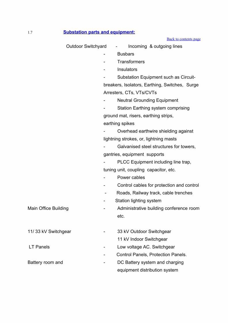
1.7 Substation parts and equipment:Back to contents page
Outdoor Switchyard - Incoming & outgoing lines
- Busbars
- Transformers
- Insulators
- Substation Equipment such as Circuit-
breakers, Isolators, Earthing, Switches, Surge
Arresters, CTs, VTs/CVTs
- Neutral Grounding Equipment
- Station Earthing system comprising
ground mat, risers, earthing strips,
earthing spikes
- Overhead earthwire shielding against
lightning strokes, or, lightning masts
- Galvanised steel structures for towers,
gantries, equipment supports
- PLCC Equipment including line trap,
tuning unit, coupling capacitor, etc.
- Power cables
- Control cables for protection and control
- Roads, Railway track, cable trenches
- Station lighting system
Main Office Building - Administrative building conference room
etc.
11/ 33 kV Switchgear - 33 kV Outdoor Switchgear
11 kV Indoor Switchgear
LT Panels - Low voltage AC. Switchgear
- Control Panels, Protection Panels.
Battery room and - DC Battery system and charging
equipment distribution system

Mechanical, Electrical - Fire fighting system Oil purification
system and other auxiliaries Substation parts
and equipment:
- Cooling water system
- Telephone system
- Workshop; stores etc.
Protection system - CTs, CVTs
- Protective Relays
- Circuit breakers
SCADA(Supervisory - Computer/Microprocessors,
Data collection
Control and Data - system, Data processing system
Acquisition System) - Man-machine interface
- Expert system etc.
1.8 Functions of Sub-station Equipments & Associated Systems Back to contents page
i) Circuit BreakersCircuit Breakers are the switching and current interrupting
devices. Basically a circuit-breaker comprises a set of fixed and
movable contacts. The contacts can be separated by means of
an operating mechanism. The separation of current carrying
contacts produces an arc. The arc is extinguished by a suitable
medium such as dielectric oil, vacuum, SF6 gas. The circuit
breakers are necessary at every switching point in the
substation.ii) Isolators
Isolators are disconnecting switches which can be used for
disconnecting a circuit under no current condition. They are
generally installed along with the circuit breakers. An isolator
can be opened after the circuit breaker. After opening the
isolator, the earthing switch can be closed to discharge the
trapped electrical charges to the ground.
iii) Current Transformers and Voltage Transformers

These transformers are used for transforming the current and
voltage to a lower value for the purpose of measurement,
protection and control.
iv) Surge Arresters
Surge Arresters divert the over voltages to earth and protect the
substation equipment from over voltage surges.
v) BusbarsBusbars are either flexible or rigid. Flexible busbars are made
of ACSR conductors and are supported on strain insulators.
Rigid busbars are made up of aluminium tubes and are
supported on post insulators.vi) Galvanised Steel Structures
Galvanised Steel Structures are made of bolted/welded
structures of angles/channels/pipes. These are used for towers,
gantries, equipment, support structures etc. Galvanised
structures provide rigid support to the various equipments and
insulators. The design should be safe and economical.
vii) Power Line Carrier Current Equipment PLCC is necessary for transmitting/receiving high frequency
signals over the power line (transmission Line) for the following:
a) Voice communication
b) Data transmission
c) Protection signalling
d) Control signalling
A small power system is generally controlled by direct
supervision of generating stations and substations through
respective control rooms. A large network having several
generating stations, substations and load centres is controlled
from central load despatch centre. Digital or voice signals are
transmitted over the transmission lines via the substations. The
substations are linked with the load control centres via Power
Line Carrier System (PLCC)/ microwave links and P&T phones.
The data collected from major substations and generating
stations is transmitted to the load control centre. The
instructions from the load control centres are transmitted to the

control rooms of generating stations and substations for
executing appropriate action. Modern power system is controlled
with the help of several automatic, semi-automatic equipments.
Digital computers and microprocessors are installed in the
control rooms of large substations, generating stations and load
control centres for data collection, data monitoring, automatic
protection and automatic control.
viii) Protective Systems in SubstationsA fault in its electrical equipment is defined as a defect in its
electrical circuit due to which the flow of current is diverted from
the intended path. During the fault the impedance is low and
fault current is high. Fault currents being high, can damage the
equipments thro’ which it flows.
Fault in certain important equipment can affect the stability of
the power system. For example, a fault in the bus zone of a
substation can cause tripping of all the feeders and can affect
the stability of the interconnected system.
The relays distinguish between normal and abnormal condition.
Whenever an abnormal condition develops, the relay closes its
contacts. Thereby the trip circuit of the circuit breaker is closed.
Current from the battery supply flows in the trip coil of the circuit
breaker and the circuit breaker opens and the faulty part is
disconnected from the supply. The entire process, ‘occurrence
of fault-operation of relay opening of circuit breaker to removal
of faulty part from the system’ is automatic and fast. Besides
relays and circuit breakers, there are several other important
components in the protective relaying scheme, these include :
protective current transformers and voltage transformers,
protective relays, time delay relays, auxiliary relays, secondary
circuits, trip circuits, auxiliaries and accessories, etc. Each
component is important. Protective relaying is a team work of
these components.
The function of different substation equipments and systems
are tabulated below in Table -5.

Table 5: Functions of different Substation Equipments & Systems
Sl.No.
Equipment Function
1. Bus-bar Incoming and outgoing circuits connected to bus-bar2. Circuit-breakers Automatic switching during normal or abnormal
conditions.3. Isolators
(Disconnectors)
Disconnection under no-load condition for safety,
isolation and maintenance.4. Earthing Switch To discharge the voltage on dead lines to earth.5. Current
Transformer
To step-down currents for measurement, control, and
protection.6. Voltage
Transformer
To step-down currents for measurement, control, and
protection.7. Lightning Arrester
(Surge Arrester)
To discharge lightning over voltage and switching over
voltage to earth.8. Shunt reactor To provide reactive power compensation during low
loads.9. Series Reactors To reduce the short-circuit current or starting currents.10. Neutral-Grounding
Reactors
To limit the earth fault current
11. Coupling capacitor To provide connection between high voltage line and
power line carrier current equipment.12. Line-trap To prevent high frequency signals from entering other
zones.13. Shunt capacitors To provide compensations to reactive loads of lagging
power factors.14. Power Transformer To step-up or step-down the voltage and transfer power
from one AC voltage to another AC voltage at the same
frequency.15. Series capacitors Compensation of long lines

16. Substation
Earthing
(Grounding)
System
-Earth mat
-Earthing spikes
-Earthing risers
To provide an earth mat for connecting neutral points,
equipment body, support structures to earth. For safety
of personnel and for enabling earth fault protection. To
provide the path for discharging the earth currents from
Neutrals, Faults, Surge arresters, overheads shielding
wires etc. with safe step-potential and touch potential.
17. Overhead earth
wire shielding or
lightning Masts.
To protect the outdoor substation equipment from
lightning strokes.
18. Illumination system
(lighting)
-for switchyard
-buildings
-roads, etc.
To provide illumination for vigilance, operation and
maintenance.
19. Protection System
-protection relay
panels
-control cables
-circuit-breakers
-CTs, VTs, etc.
To provide alarm or automatic tripping of faulty part from
healthy part and also to minimise damage to faulty
equipment and associated system.
20. Control cabling For protective circuits, control circuits, metering, circuits,
communication circuits. 21. Power cables To provide supply path to various auxiliary equipment
and machines.22. PLCC system
power line carrier
current system
-line trap
-coupling capacitor
-PLCC panels
For communication, telemetry, tele-control, power line
carrier protection etc.
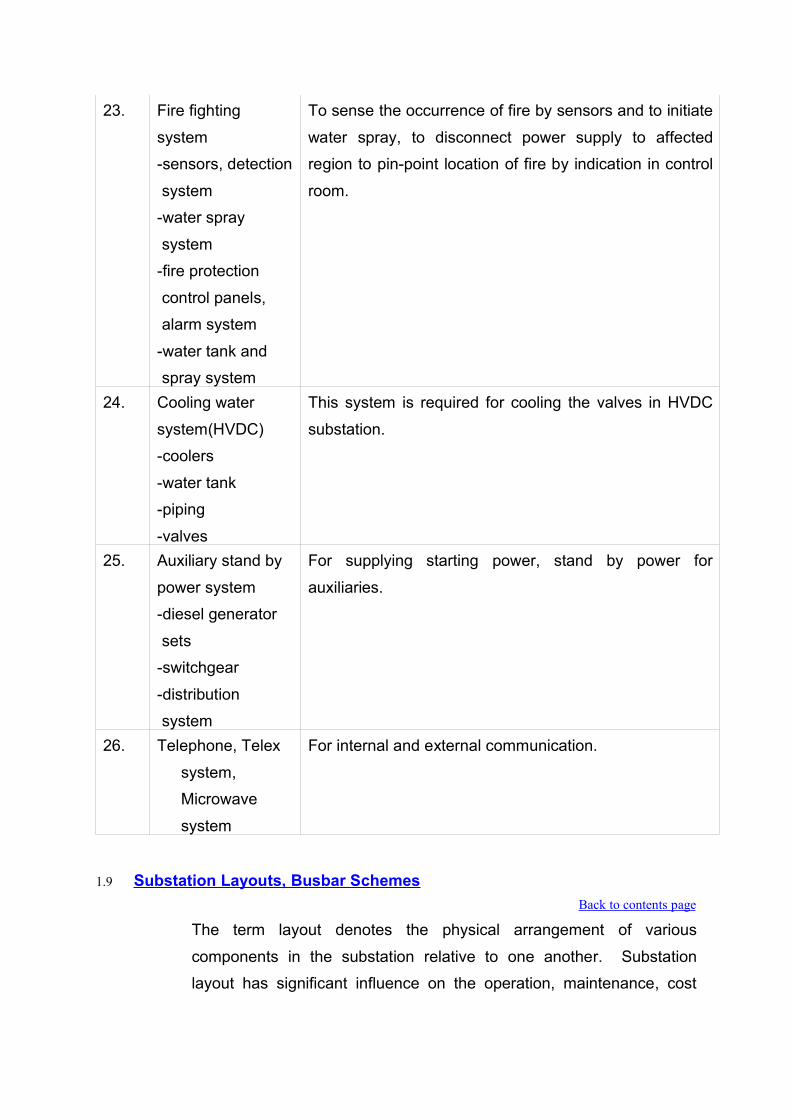
23. Fire fighting
system
-sensors, detection
system
-water spray
system
-fire protection
control panels,
alarm system
-water tank and
spray system
To sense the occurrence of fire by sensors and to initiate
water spray, to disconnect power supply to affected
region to pin-point location of fire by indication in control
room.
24. Cooling water
system(HVDC)
-coolers
-water tank
-piping
-valves
This system is required for cooling the valves in HVDC
substation.
25. Auxiliary stand by
power system
-diesel generator
sets
-switchgear
-distribution
system
For supplying starting power, stand by power for
auxiliaries.
26. Telephone, Telex
system,
Microwave
system
For internal and external communication.
1.9 Substation Layouts, Busbar Schemes Back to contents page
The term layout denotes the physical arrangement of various
components in the substation relative to one another. Substation
layout has significant influence on the operation, maintenance, cost

and protection of the substation and these aspects are considered
while designing the substation layout.
The reasoning behind the connections of components in each circuit
and the busbars layout should be understood. Within the frame-work
of the basic requirements, the substation layout can have several
alternative arrangements. The substation layouts are selected on the
basis of the size, the ratings, importance, local requirements and the
prevailing practice of the supply authorities. The different bus-bar
schemes in a substation with their relative advantages/disadvantages
are described below:
The choice of busbar schemes for AC yards depend upon several
factors mentioned above. The important busbar schemes include the
following:
Single busbar
Double busbar with one breaker per circuit.
Double busbar with two breakers per circuit.
Main and transfer bus
Ring bus
Breaker and a half arrangement
Mesh arrangement etc.


Table : 6 Various Bus-Bar Schemes
Sl.No.
Scheme Application Remarks
1. Single bus-bar Low voltage and medium
voltage substations
Not preferred for important/
large substations
- Cheapest
- Total shutdown in case of a
fault
- In case of maintenance of
circuit breaker, associated
feeder has also to be shut
down 2. Duplicate Bus High voltage substations - Costlier than single bus
- One bus can serve as a
reserve.
- During maintenance or
fault, the reserve bus is
used
- More flexibility of operation
- Buses are sometime
sectionalised & the bus
coupler breaker is
connected in between two
buses3. Double Main
and Transfer
Bus
Important EHV substations - Additional flexibility for
operation
- Fault on one bus will not
cause a complete outage of
the station.4. Breaker & a
half scheme
Important 400 kV
substations
- Uses three breakers for two
circuits
- High flexibility operations
- Higher costs
- Suitable for those
substations which handle
large amounts of power on
each circuit

5. Mesh System Used for large substations
having many incoming and
outgoing circuits.
- Costlier
- Gives good
operational flexibility
- Suitable where no. of
circuits are comparatively
few & chances of future
expansion are less
1.10 Construction/Erection DrawingsBack to contents page
Lists of construction/erection drawings used during Civil and other
construction activities in a substation are enclosed at Annexure-3 and
Annexure-4.

Annexure-3Back to contents page
A. Control Room Building1. Ground floor Plan & Elevators
2. Mezzanine Floor Plan & Elevations
3. Elevation, Section & Terrace Plan
4. Foundation Plan-Excavation drawing
5. Foundation & column up to first floor
6. Details of plinth beams
7. Mezzanine floor beams & reinforcement details
8. Mezzanine floor slab & reinforcement details
9. Mezzanine floor insert details
10. Lintel & Chhajja details
11. Roof slab reinforcemet details
12. Roof beam details
13. Roof slab insert details
14. Details of foundation for A/C plant room
15. GA & RCC details of foundation for cooling tower supporting structure
16. Internal cable trench details
17. Details of steel & window details
18. Aluminium glazing window details
19. Fire resistance door/siding door details
20. Details of toilet & pantry
21. Plumbing details
22. Details of septic tank
23. Finish schedule
24. Colour scheme
25. Electrical wiring drawings
B. DG Set Building1. Plan elevations and sections
2. Foundation layout and RCC details of slab flooring, columns, beams.
3. Details of brick wall foundation, columns and intel.
4. Details of doors and windows.
5. DG set foundation and cable trench layout and R/F details.

6. Colour scheme and misc. details, monorail fixing details.
7. Electrical wiring, insert fixing details.
C. F.F. Pump House1. Plan, elevation and sections
2. Foundation layout, RCC details of slab, footing, column beam.
3. Terrace plan and Misc. Details.
4. Details of water tanks.
5. Details of doors, window, ventilators and rolling shutters.
6. Equipment foundation, cable trench layout and reinforcement details.
7. Electrical wiring drgs., insert details.
D. Internal Roads and Drains1. Layouts of internal roads and drains.
2. Layouts and cross sectional details of roads and drains.
3. Layout of culverts and drains.
4. Details of culverts and drains.
E. Boundaries Wall and Fencing1. Boundaries wall and fencing details
2. Fencing and gate details
F. Shunt Reactors1. GA and foundation details.
2. Pylon support details
G. Auto Transformer1. GA and RCC details of foundation, General arrangement
2. Pylon support details
3. Details of rail track
4. Fire protection wall between auto-transformer
H. Approach Roads and Drains1. Layout of approach roads and drains.
2. Layout and C/S details of roads and drains.
3. Layout of drains and culverts
4. Details of culverts and drains.
I. Site Office and Store Complex1. Material store plan, Elevation and sections
2. Crane store plan, Elevationa and Sections.

3. Site office plan, Elevation and sections.
4. S/S store Plan, Elevation and sections.
5. Cement store Plan, Elevation and sections.
6. Details of raised platform.
7. Store complex layout plan.
8. Store complex TL material store.
9. Store complex TL material store.
10. Crane store foundation plan, roof plan and beam details.
11. S/S store foundation plan, roof plan and beam details.
12. Cement store foundation plan, roof plan and beam details
13. Details of entrance gate and fencing
14. Type section of tabular truss.
15. Details of doors and windows.
16. Finish schedule of site office and store complex.
17. Layout ext. drainage and sewerage system
18. Details of septic tank and soakpit.
19. Toilet and kitchen detail-site office
20. Toilet and kitchen details-S/S. store
J. Structural arrangement1. Design of towers and beams
2. Fabrication drawings of tower & beams
3. Tower foundation and their designs
4. Design of equipment supporting structure
a) CT
b) CVT
c) LA
d) Bus Post Insulator
e) Isolator
f) Wave Trap
g) Circuit Breaker
5. Equipment supporting structure fabrication drawings
a) CT
b) CVT
c) LA

d) Bus Post Insulator
e) Isolator
f) Wave Trap
g) Circuit Breaker
6. Details of foundation bolts
a) Equipment Structure
b) Gantry Structure
7. Design of equipment foundations & foundation details
8. Cable trench layout
9. Cable trench section details
10. Cable trench road crossings
11. Marshalling box foundation
12. Sump pit
List of construction Drawings for Township Work in a typical Sub-station
A. Quarters for Type A,B, C and D1. Architectural plan, Elevation
2. Architectural section, terrace plan
3. Foundation plan, Plinth beam layout
4. Details of foundation
5. Details of roof slab, first floor slab, lintel etc.
6. Electrical layout
7. Sanitary layout and plumbing details
A. Master Layout1. Plan
2. Electrical layout
3. Sewerage layout
4. Plumbing layout
5. Layout of drains and road.
B. Overhead and underground Water-Tank1. Architectural Drawings’
2. Structural details
3. Foundation Details
C. Non Residential Buildings(Nursery school, Dispensary and shopping centre)
4. Architectural plan and Elevation
5. Structural Details
6. Services
D. Administrative Building7. Architectural plan and Elevation
8. Structural details
9. Services

Annexure-4Back to contents page
List of drawings for a typical Sub-stationA. Sub-Station Drawings1. Single line diagram
2. General arrangement of substation’
3. Electrical layout (Plan and Section)
4. Electrical clearance diagram
5. Switchyard structural layout arrangement
6. Layout of equipment structures
7. Busbar support design and design calculations
8. Cable trench layout and foundation plan
9. Details of cable trench section
10. DSLP calculation
11. Drawing of DSLP scheme
12. Earthmat design calculation
13. Equipment/structure earthing details
(List all relevant drawings, under this heading)
a) Earthmat layout
b) Erection key diagram (Plan and Section)
c) Bill of Quantity
14. Short circuit force and critical span calculation(for spacers)
15. Design calculation for sag-tension and stringing chart
16. Power cable schedule
17. Inter pole cable schedule
18. Buried cable trench layout
19. OGA drg. for bus post insulator
20. Individual insulators detail drg. for bus post insulator
21. Detail drg. for bottom & inermediate flanges
22. Cap detail drg. for bus post insulator
23. Corona ring for bus post insulator
24. GA of bay marshalling kiosk
25. Schematic & wiring diagram of bay marshalling kiosk
26. Tension/suspension string insulator and hardware assembly

27. 120KN antifog disc insulator GA drg.
28. Clamps, connectors and spacers GA drg.
29. ACSR conductor, Al tube & shieldwire
30. GTP data sheets
31. Cable trays GA drawing
32. GA drg. for double compression type cable gland
33. Drum drg. for ACSR conductor and earthwire
B. 245KV SF6 Circuit Breaker1. Outline general arrangement drawing of C.B. indicating major parameters.
2. Outline general arrangement drg. of control cabinets and their foundation plan
and separate drawing showing component layout.
3. Outline general arrangement drg. of support insulator.
4. Interrupter insulator, insulator & insulator for grading capacitor showing clearly
the shed profile and parameters.
5. Support structure and foundation plan drawing with necessary support
structure design calculations.
6. Electrical schematic diagram including brief write up on operation.
7. Rating and name plate drawing.
8. Air/SF6 gas connection diagram
9. Schematic diagram of electro hydraulic operated mechanism in case of
hydraulic drive.
10. Wiring diagram
11. Terminal conenctor and corona ring drawings
12. Sectional view of SF6 gas couplings.
13. Sectional view of interruptor, voltage grading device identifying each part of
the assembly.
14. Following additional drawings for Unit air compressor:
a) Foundation plan and details for compressor and motor
b) Unit of contact manometer assembly.
C. 245KV Isolator1. Outline drawing of isolators with one E/S
2. Outline drawing of isolators with two E/S
3. Outline drawing of isoaltor without E/S
4. General arrangement of contact assembly.

5. Terminal pad and hinge contract.
6. Loading data.
a) GA of motor operated mechanism
b) GA of support insulator
7. Details of constructional interlock
8. Name Plate details
9. Drawings for terminal connector & corona rings.
10. Drawing for base frame.
11. Schematic drawings.
12. Wiring diagram & inerpole connection diagram.
13. Drawing for motor operated mechanism/manually operated mechanism, as
applicable with door open and identifying all parts of the mechanism and the
control panel.
14. Drawing for support structure.
D. 245KV Current Transformer1. Outline drawing of C.T. indicating major parameters.
2. Sectional view of C.T.
3. OGA of marshalling box
4. OGA of secondary terminal box
5. Wiring diagram of marshalling box(including interpole wiring).
6. Magnetisation curve.
7. Name plate.
8. Drawing of terminal connectors.
9. Drawing of corona ring.
10. Drawing for stool/sub-structure, if applicable.
11. Drawing for support structure.
E. 245KV Capacitor Voltage Transformer1. Outline drawing of CVT indicating major parameters.
2. Sectional view of CVT.
3. OGA of secondary terminal box.
4. OGA of marshalling box.
5. Wiring diagram of marshalling box (including interpole wiring)
6. Drawing for terminal connectors
7. Name plate drawing.

8. Drawing for stool/sub-structure, if applicable.
9. Drawing for support structure.
F. 245KV Class Surge Arrester1. OGA of Surge Arrester indicating major parameters.
2. Foundation details.
3. Insulating base drawing.
4. Discharge counter/surge monitor drawing
5. Method of connecting surge monitor with SA
6. Electrial schematic diagram of surge monitor
7. Ground terminal bracket details
8. Name plate drawing
9. Line teminal bracket drawing along with corona rings
10. Residual voltage verses discharge current curves
11. Drawing for stool/sub-structure, if applicable
12. Drawing showing internal view of SA
13. Drawing of Insulator
14. Drawing showing pressure relief arrangement
15. Support structure drawing.
G. Power and Control Cables1. Data sheet of all types of power cables
2. Data sheet of all types of control cables
3. Power cable schedule
4. Control cable sizing/section criteria
5. Control cable laying & termination schedules

List of Drawings for Erectin of C&R panels in a typical Sub-Station
1. Data requirement sheet with literature.
2. Type test report for all equipments.
3. Board formation redrawings.
4. Foundation details.
5. General arrangement of control panel/feeder.
6. General arrangement of relay panel/feeder.
7. Schematics of control panel/feeder.
8. Schematics of relay panel/feeder.
9. Cable schedule.
a) Inter panel schedule.
b) Cable laying schedule.
c) Cable terminating schedule.
10. Equipment layout drgs.
11. Relay settings.
12. As built drgs. And manuals for circulation.

List of drawings for Erection of PLCC panels in a typical Sub-Station
1. Data requirement sheet with literature.
2. Type test report for all equipments.
3. General arrangement of PLCC system.
4. Equipment drgs.
a) PLCC panel for speech and data.
b) PLCC panel for speech and protection.
c) Protection couplet.
d) Wave Trap.
e) Coupling Device.
f) EPAX
g) 4 wire/2 wire Telephone
5. Frequency Plan
6. As built drawing

Chapter-2SWITCHYARD CIVIL WORKS

CHAPTER TWO
SWITCHYARD CIVIL WORKS
Back to contents page
2.0 Introduction Back to contents page
Civil works in a substation mainly comprise of :
Construction of equipment foundations transformer/reactor plinth,
structure foundations
Cable trenches
Fencing around switch yard
Surface treatment, ground filling and sloping
Water supply system & Sewerage system
Construction of roads and drains
Construction of control room building, compressor room, offices,
repair / maintenance bay and other non-residential buildings
Construction of railway, siding and railway track if required
Construction of residential colony
Horticulture works
Administrative Building, community centre, guest house/transit
Camp, shopping complex & nursery school etc.
For carrying out the various civil works at site which is initially an open
barren/cultivated land, initially survey of land is carried out alongwith
the soil investigation. Survey is done to finalise the levels of switchyard,
roads and design & layout of drainage system in the switchyard as well
as in the township. Fix & permanent bench mark is provided for
adopting it as a reference point for various works like laying out of
control room, erection of gantries and various equipments, foundations
and buildings in the switchyard that are done in reference to this
permanent bench mark. Now grid lines are required to be marked in
East-West and North-South direction by erecting the concrete grid

pillars. Grid lines are marked on the land to fix the direction &
orientation of various civil structures with reference to some fixed
bench mark on the site. These gridlines help in implementing the
erection, orientation and layout of foundations for various equipments &
control room building which is later on helpful in laying out the other
equipments and structures on the land.
2.1 Soil Investigation Back to contents page
Soil investigation is carried out at site and result of soil investigation
are forwarded to Corporate Centre for design of various
foundations.
Detailed soil investigation is carried out at site to arrive at
sufficiently accurate, general as well as specific information about
the soil profile and necessary soil parameters of the site in order
that the foundations of various structures can be designed and
constructed safely & rationally.
The soil investigation tests should be conducted at all the critical
locations i.e. control room building, auto transformer, shunt reactor,
lightening masts, 400 KV tower locations etc.
Engineering department at Corporate Centre prepares the
foundation drawings and approved drawings are sent to site for
casting.
Engineering Department also releases various other erection
drawings for different works like cable trench design drawings,
cover slab design drawings, overall layout of equipments in
switchyard, equipments erection key drawings etc. for erection
works at site. During this period, the site levelling work is carried
out at site in order to smoothen the undulations.
2.2 Levelling Back to contents page
The land acquired for substation may be barren/cultivated land. The
soil may be rocky, black cotton, sandy or any other type. The acquired
land may contain trees, bushes, crop, drains, etc. that require cleaning/
clearing before starting the levelling works in the yard.

i) Switchyard area is important and preferably it should be brought to
a single level. However, in only unavoidable circumstances or
where it is uneconomical to go for levelling the soil than keeping a
multi-layered/in steps levels, the different levels may be kept.
ii) Levelling may also be required in township area for bringing the
land to a single level for designing the drainage system and
residential quarters. In case of too much level difference the
residences (categories) may be designed at different uniform levels
but with good drainage system to avoid water logging.
iii) Before starting the levelling works the marked area of switchyard is
cleaned. Any crop, bushes, trees, shrubs and structure that may
cause hindrance or that are undesired are cleared from the yard
area.
iv) Any drain, telephone line, building structure is also removed from
the switchyard area, to a nearby suitable place.
v) Now spot levels will have to be taken in the yard area before
making an assessment for the levelling i.e. for assessing the
requirement of soil for low level areas and cutting of soil from high
level area to bring the whole yard area to a normal formation level.
vi) In the ideal case of levelling there is no requirement for borrowed
earth and quantity of earth excavated from the high level and fill it in
the low lying areas is equal. This is the most economical method of
levelling. Care is to be taken such that the earth is not excavated
below the formation level.
vii) For compaction earth is filled in the low lying areas in layers of 20
cm thickness then watered and compacted by rollers/ dozers.
viii)The method and equipment used to compact the fill material to a
density that will give the allowable soil bearing pressure required for
the foundations, roads, etc. In each layer of fill material. Each layer
of earth embankment when compacted should be as close to
optimum moisture as practicable. Embankment material which
does not contain sufficient moisture to obtain proper compaction
should be wetted. If the material contains an excess of moisture,
then it should be allowed to dry before rolling by hand
rollers/dozers. No compaction is carried out in rainy weather.

ix) Sometime in hills or in rocky soil, we may have to go for blasting the
earth at higher levels. The blasting is done in the specified manner.
All safety precautions should be taken while blasting so as to avoid
any injury/loss of life and property. The explosive material used for
blasting should be handled very carefully. While applying the
explosive material for blasting, one should take care such that the
earth excavated/hole created by blasting is upto/very near the
desired ground level.
x) The levels in the entire area (after finishing the levelling work)
should be taken and checked up with the desired formation level.
Final dressing up and finishing should be done in case if levels are
not found satisfactory. The care should however be taken during
compaction. Measurement for levelling work (i.e. excavation &
filling) is a cumbersome process and it should be done strictly as
per the specifications. All the level records must be noted in field
levelling book duly signed by the concerned personnel of contractor
of site. The drawings of level before starting the levelling and then
final levels should be maintained. The measurements should be
recorded very carefully as per the technical specifications. Care
should be taken that with the movement of trucks, dozers etc. any
other structure in the vicinity is not affected or uprooted.
2.3 Foundations Back to contents page
Foundations in switchyard area the foundations are cast for:
i) Lattice Structure (Tower foundations) i.e. for gantries, lightening
masts etc.
ii) Cable trenches
iii) Equipment in switchyard
Based on the approved layout drawings furnished by Corporate
Engineering the foundations are marked on the ground.
While marking the foundations on the ground their layout should
be strictly verified with the layout drawings as well as with the
bench mark/grid lines on site with great accuracy.

Layout of the various switchyard equipments is also verified with
the layout drawings and with respect to gridlines on the ground.
For further confirmation, the control room building co-ordinates
can be used and necessary rectification in the layout & orientation
of various equipments and foundation can be made.
Any changes in layout if desired should be brought in the notice of
Corporate Engineering and necessary amendments should be
approved. It is a good practice to have a second confirmation for
marking the various foundations w.r.t. control room co-ordinates
that are fixed and marked before hand.
Foundations for various lattice structure are cast in the switchyard
area. The type of foundation is decided based on the type of soil.
Engineering Department at Corporate Centre provides the
necessary tower foundation, excavation and concreting work
drawings based on the soil investigation reports furnished to
them.
2.4 Foundations for Transformer & Shunt Reactors Back to contents page
i) Transformer of 400/220/33 kV, 315 MVA capacity is generally
provided at our substation sites. Transformer and shunt reactors
are the major equipments in switchyard. Their transportation,
storage, foundation and installation require special techniques
and efforts.
ii) Transformer & shunt reactor foundation work includes the supply
of a permanent track system to enable the replacement of any
failed unit by the spare unit located at the site. It also includes the
concreting, providing jacking pads, steel work for the MS grating
and providing the anchoring arrangement.
iii) The foundations for transformer & shunt reactor should be ready
in advance before actual receipt of the equipments. Proper co-
ordination in the works are required so that the foundations are
completed well in advance.
iv) For casting the foundation of Transformer & Shunt Reactor the
marking is done as per the approved drawings from the Corporate

Engineering Department. The marking of co-ordinates should be
checked properly and reconfirmed with the control room and
switchyard layout co-ordinates. The pylon supports that are
required to be laid before the concreting works is generally in the
scope of fire fighting contractor. Scheduling of such works should
be co-ordinated between the contractors for smooth working & to
avoid any stoppages in work.
2.5 Cable Trenches in Switchyard Back to contents page
i) The cable trench drawings are received by site from the
Corporate Engineering Department Based on these drawings
cable trenches are cast at site.
ii) The cable trenches are marked on ground and excavation is
started by the contractor on the marked trenches.
iii) Before starting the RCC the land should be levelled, smoothened
and then laid with PCC of required thickness. Proper care should
be taken during RCC casting.
iv) The centre line of cable trench (marked before excavation) should
be rechecked during the lean concerning to avoid any mistakes in
marking.
v) The slope in cable trenches is provided in such a way that the
water from secondary cable trenches flows towards the primary
cable trenches. The slope of primary cable trench is maintained
in such a way that the rain water may go in a sump on the other
side of the primary cable trench by gravity itself.
vi) Before starting the concreting, shuttering is provided for cable
trench walls. Provision should be made at this time to insert the
cable supporting angles and other steel reinforcements in the
cable trench walls.
vii) Concreting of cable trenches can be started after all the wall
inserts bends etc. have been inserted properly. Necessary
expansion joints generally made up of PVC or specified material
of designed size should be inserted at the specified length of
cable trench walls.

viii) Top of the trenches is kept at least 150 mm (or as specified)
above the furnished ground level such that the surface rain water
does not enter the trench.
ix) All metal parts inside the trench are connected to the earthing
system.
x) Trench wall should not foul with the foundations. Suitable clear
gap is maintained.
xi) A slope of 1/500 is provided in the trench bed along the run and
1/250 perpendicular to the run or as specified.
xii) All construction joints of cable trenches i.e. between base slab to
base slab & the junction of vertical wall to base slab as well as
from vertical wall to wall and all the expansion joints are to be
provided with approved quality PVC water stops of the specified
size. This is required in all the sections where the ground water
table is expected to rise above the junction of base slab and
vertical wall of cable trenches.
xiii) All the inserts exposed surfaces are be brushed with metal wire
brushes.
xiv) Cable supports are welded at the right level and painted with the
specified paint.
xv) All cable trenches are cleaned after the cable trench work is
completed.
2.6 Cable Trench Cover Slabs Back to contents page
i) Precast removable concrete covers are to be provided on the
cable trenches.
ii) These covers slabs are designed to cover the open trenches in
which cables are placed.
iii) Concrete cover slabs are cast by using metallic shuttering of
suitable size.
iv) The shuttering should not be deformed otherwise cover slabs will
also be deformed and become out of shape.
v) After casting the slabs, shuttering should be removed after 24 hrs.
and proper curing of cover slabs should be done for at least 10
-14 days.

vi) Cover slabs are placed over the cable trenches after the cables
have been laid.
vii) The cover slabs over cable trench are joined with cement mortar
and generally the tenth cover in a line is kept free from joining
with provision of lifting hook. This is done so that the covers can
be removed for regular inspection of cable trenches during
maintenance.
viii) Cover slabs are placed on cable trenches after completion of
cable laying.
2.7 Anti-weed Treatment, Micro Levelling Gravel Filling & Metal Spreading Back to contents page
2.7.1 Anti-weed Treatment Back to contents page
i) The soil of the entire switchyard area is subjected to
sterilisation/anti-weed treatment before the site surfacing/gravel
fill material. The treatment is done strictly as per instruction of the
manufacturer of the chemical required for soil sterilisation/anti-
weed treatment.
ii) After all the structures and equipments have been erected and
accepted, and soil sterilisation (as specified) is complete, the site
should be maintained to the lines and levels and
rolled/compacted by using roller of specified capacity with
suitable water sprinkling to form a smooth and compact surface
condition which should match with finished ground level of the
switchyard area.
2.7.2 Micro Levelling Back to contents page
i) After the soil sterilisation and application of anti weed treatment
the surface is prepared for levelling to the required level.
ii) The switchyard are is used by various contractors & executing
agencies for the various works like laying of earth mat excavation,
foundation casting & backfilling of earth, equipments erection,
cable laying in the cable trenches and piping work for fire fighting
systems.

iii) After completion of different works the various agencies working
in switchyard should remove their set up like construction power
cables, water pipe lines, sand, metal & other construction
materials and T&P etc.
iv) The heavy vehicles like cranes, trucks and other transport modes
move in the switchyard area. This movement causes a change in
the switchyard level causing lot of undulations in the earth level.
The earth that was earlier levelled now again requires some fine
levelling to bring it back to original finished desired level.
v) This process of removing the surplus earth and filling it at the low
lying areas so as to maintain one level is done after completion of
various works in switchyards. This laid earth is then duly
compacted.
vi) The method of compaction is same that water is poured over, the
layer of specified check thickness of earth and the layer of such
earth is then compacted using compaction tools. Again a layer is
laid and water is poured in it and the earth is again compacted.
vii) This process of refilling and compaction goes on until the required
level of earth is achieved. Care should however be taken that
during excavating the excess earth (for refilling at the low level) the
earth is cut and removed only upto the required level and not
below otherwise this area may again require some refilling causing
wastage of labour.
viii) The important thing in micro levelling is the backfilling and
compaction. If both are not done properly the earth level may
come down after some time (after rains etc.) making it low lying
area. In case of some reservations over the degree of compaction
of backfilling the specified tests can be performed.
2.7.3 Metal spreading in Switchyard Back to contents page
i) The area where metal spreading is to be done is measured for
quantity of metal required for filling.
ii) Hard granite store of 40 mm nominal size is spreaded in different
stages. Under size and over size metal should be rejected.

iii) The metal stacks are placed at a designated place and these are
measured and recorded before actually spreading in the
switchyard metal is spreaded in the layers of 100 mm.
DO’S DON’T’S&
SPECIAL PRECAUTIONS

2.8 Do’s , Don’ts & Special PrecautionsBack to contents page
i) Whenever water table is met during the excavation, it should be
dewatered and water table maintained below the bottom of the
excavation level during excavation, concreting and backfilling.
ii) The method and equipment used to compact the fill material should
be suitable to achieve the density that will give the allowable soil
bearing pressure required for the foundations, roads etc. In each
year of fill material.
iii) Minimum 75 mm thick lean concrete (1:4:8) or as specified should
be provided below all underground structures, foundations,
trenches etc. To provide a base of construction.
iv) Necessary protection to the foundation work, if required should be
provided to take care of any special requirements for aggressive
alkaline soil, black cotton soil or any other type of soil which is
detrimental/harmful to the concrete foundations.
v) RCC columns should be provided with rigid connection at the base.
vi) Only approved admixtures should be used in the concrete for the
Works. When more than one admixture is to be used, each
admixture is batched in its own batch and added to the mixing water
separately before discharging into the mixer.
vii) The water-reducing set-retarding admixture if used should be of
approved brand
viii)The water roofing cement additives shall be used as
required/advised by the consignee.
ix) The concreting of trench should be arranged for a length of not
more than 30 mtrs. at a time.
x) Bar bending schedule for raft and trench wall should be prepared as
per the drawing and same should be checked for placement.
xi) To meet the commissioning schedules, the priority areas are to be
identified and the construction of foundations and cable trenches
should be taken up in stages and priority-wise.

xii) Wherever earth mats are crossing the cable trench suitable U
bends of MS rounds should be placed below the trench raft before
concreting.
xiii)A separate sump should be constructed for curing the cover slabs.
xiv)The cover slab should be kept in water sump for a period of about
10 days for curing.
xv) Due care should be taken so as not damage any foundation
structure or equipment during rolling/compaction.
xvi)The gravel should be allowed to come from one or two approved
quarries where the similar gravel availability is possible.
xvii)The stone should be hard, coarse and it should not be flat.
xviii)The quantity required to fill up a measured area should be
ascertained actually. Then the metal of adequate measurement
should be spread in this area.
xix)Use of undersize & oversize metal than the specified size should be
avoided. A 20 mm sieve can be used to remove the oversized
gravel.
xx) The material required for site surfacing/gravel filling should be free
from all types of organic materials and should be of standard
approved quality, and as directed by the Engineer-in-charge.
xxi)The rail and concrete sleepers are required for providing the track
for transformer and shunt reactor unit. These items are required to
be procured from the market. The items are of specific dimension
and requirement. Their availability in the open market may not be
easy so efforts to procure these items should be started
simultaneously while the works for foundation are started.

CHECK FORMAT

2.9 Check FormatBack to contents page
1. Soil investigation report has been approved by competent authority Yes/No
2. Construction drawings are being released by Engg. deptt. Yes/No3. Grid pillars are erected at site. Yes/No4. Grid lines are formed as per designed layout at site Yes/No5. Centre line marking for cable trench is checked as per drawing Yes/No6. Proper slope of main and all secondary cable trenches is
maintained
Yes/No
7. Bar bending schedule trench walls and raft is approved Yes/No8. Nosing angles and inserts for fixing cable supports have been
provided in trench wall
Yes/No
9. For concreting proper shuttering is provided in cable trenches Yes/No10. Required water stoppers at the specified trench length has been
provided
Yes/No
11. Concreting of trenches/raft done as per specifications Yes/No12. U bends have been provided in cable trenches where these cross
the earth mats.
Yes/No
13. For equipment foundations location exact co-ordinates are verified Yes/No14. All levelling work is complete before start of foundations Yes/No15. All materials like sand, cement, metal, foundation bolts etc. are
available with adequate T&P before start of foundation activities
Yes/No
16. Cable trench cover slabs being cast on special platform and with
proper shuttering
Yes/No
17. Proper curing of cover slabs is being done Yes/No18. When placed on trenches (after cable laying etc.) joints have been
sealed
Yes/No
19. For transformer & shunt reactor foundations pylon supports have
been provided by the concerned agency
Yes/No
20. Layout of foundation is verified with switchyard layout drawing Yes/No21. Rail and sleepers have already been procured before start of
concreting at site
Yes/No
22. All cable trench work, backfilling and cable trench cover slabs have
been provided
Yes/No

23. Earth mat work is complete Yes/No24. Site is cleared from any construction material and power cables and
all T&P has been removed from site
Yes/No
25. Microlevelling work is being done satisfactorily and the desired site
level is achieved
Yes/No
26. Earth required for low lying area is being cut from high level areas Yes/No27. Proper compaction of land as per specifications is being done Yes/No28. Before micro levelling all foundations have been properly backfilled Yes/No29. All metal/hard granite is properly stacked for recording Yes/No30. Hard granite metal store of specified size is spreaded Yes/No31. Metal is being brought from the selected/approved queries Yes/No32. Proper level marks for spreading and measurement of metal have
been provided
Yes/No
33. Metal spreading is completed and proper recording/measurements
have been taken
Yes/No

CHAPTER-3SWITCHYARD EARTHING

___________________________________________________________________________ CHAPTER
THREE___________________________________________________________________________
SWITCHYARD EARTHINGBack to contents page
3.0 Introduction Back to contents page
The object of earthing is to maintain a low potential on any object. The
purpose of a earthing system in a substation area is to limit the
potential gradient within and immediately outside the area to a value,
safe for the working personnel. Safety is to be ensured under normal
as well as abnormal operating conditions.
3.1 Functional Requirements of Earthing System Back to contents page
To provide earth connection for the neutral points of transformer, reactor,
capacitor banks, filter banks, generators.
To provide discharge path for lightning overvoltages coming via rod-gaps,
surge arresters, shielding wires etc.
To provide low resistance path to earthing switch earthed terminals, so as to
discharge the trapped charge to earth prior to maintenance or repairs.
To ensure safety of operating staff by limiting voltage gradient at ground level in
the substation.
To provide a sufficiently low resistance path to earth to minimise the rise in
earth potential with respect to a remote earth-fault. Persons touching any of
the non-current carrying earthed parts shall not receive a dangerous shock
during an earth fault. Each structure, transformer tank, body of equipment etc.
should be connected to earthing mat by their own earth connection.
3.2 Earthing System in Switchyard Back to contents page
Following basic requirements are to be satisfied as so to ensure a
proper and sound earthing system in substation switchyard.
i)The earth resistance for the switchyard area should be lower than a certain limiting
value “Ra” in order to ensure that a safe potential gradient is maintained in the

switchyard area and the protective relay equipments operate satisfactorily. For major
switchyards and substations in India, this limiting value of earth resistance (Ra) is
taken to be less than 0.5 ohm.
ii)The grounding conductor material should be capable of carrying the maximum
earth fault current without overheating and mechanical damage. The maximum fault
level in the 400 KV system has been estimated to be 40 kA and this value of fault
current is used in the design of earth mat for the 400 KV substation.
iii)All metallic objects which do not carry current and installed in the substation such
as structures, parts of electrical equipments, fences, armouring and sheaths of the
low voltage power and control cables should be connected to the earthing electrode
system.
iv)Mechanical ruggedness of the ground conductor should be ensured.
v)The design of ground conductor should take care such that whenever a fault
occurs in substation, fault current flows through the faulty circuit to the connecting
electrode.
3.3 Step and Touch Potential Back to contents page
Any person in the substation area is likely is encounter the following
potential rises.
i)The station earthing system should have earth resistance lower than 0.5 ohm for
effective discharge of lightning over voltage to earth.
ii) Grounding mesh is provided below ground level. Earth electrodes are
driven into ground at several points and are connected to the
grounding mat to form Earthing Mesh. All the structures, transformer
tanks, etc. are connected to this mesh.
3.3.1 Step potentialBack to contents page
The potential difference between two steps of a person standing on the
substation floor during the flow of earth fault current is known as step
potential.
3.3.2 Touch potential Back to contents page
The potential difference between a step and the tip of the raised hand
touching a substation structure during the flow of the earth fault current
through the latter is known as touch potential.

The step potential and touch potential depend upon the following
aspects:
Earth fault current
Duration of earth fault
Whether short time (less than 3 sec.)
Whether sustained (more than 3 sec.)
Fault current flowing through body
Values of body resistance in the path
The design of grounding system should be such that the voltage
gradient in volts/metre on the surface of the ground should be less than
the permitted value.
3.4 Soil Resistivity Measurement Back to contents page
The earth resistivity is measured by driving 4 electrodes in ground in a
straight line at equal spacing of 20-25m (Fig. 1). These electrodes are
connected to terminals of an earth tester. A typical earth tester has 4
terminals C1, C2, P1 and P2. The electodes are connected to the
tester in the order of C1, P1 and P2, C2. The handle of the tester is
rotated in case of manual one or the button is pressed (in case of
motorised tester) and the reading of the resistance is read on the
megger scale. The reading of meggar is used in calculating the soil
resistivity in Ohm-meters.


If R is the resistance measured then the
Specific Resistivity = 2 aR
where a= Distance between the electrodes
The design of earth mat is based on the results of earth resistivity
measured in the switchyard area. The earth resistivity is taken at about
15 places in switchyard and more particularly near shunt reactor,
transformer, Circuit Breaker and control room locations.
Prior to the testing of soil resistivity and earth resistance, site should
refer to the guidelines issued by the Operation Services Deptt. at
Corporate Centre. The operation manual of the testing instrument
available at site should also be referred.
3.5 Earthing Material Back to contents page
Following Table gives the typical size and materials required for
different earthing items in the substation:
Table -1: Typical sizes of materials used for Switchyard Earthing
Sl. No. Item Size Material1. Main Earthing Conductor to be buried
in ground (for earthed mat & earth
pipes)
40 mm dia Mild Steel rod
2. Conductor above ground & earthing
leads (for equipment)
75 x 12 mm
G.S. Flat
Galvanised Steel
3. Conductor above ground & earthing
leads (for columns & aux. Structures)
75x12 mm
G.S. Flat
Galvanised Steel
4. Earthing of indoor LT panels, Control
panels and out door marshalling
boxes, MOM boxes, junction boxes &
lighting panels etc.
50 x 6 mm
G.S. Flat
Galvanised Steel
5. Rod Earth Electrode 40 mm dia
3000 mm
long
Mild Steel
6. Pipe Earth Electrode (in treated earth
pit) as per IS.
40 mm dia
3000 mm
long
Galvanised Steel

7. Earthing for motors 25 x 3 mm
GS flat
Galvanised Steel
8. Earthing conductor along outdoor
cable trenches
50 x 6 mm
MS flat
Mild Steel
3.6 Earthing Conductor Layout Back to contents page
i) Earthing conductor in outdoor areas is buried at least 600 mm
below finished ground level or as specified.
ii) Wherever earthing conductor crosses cable trenches, underground
service ducts, pipes, tunnels, railway tracks etc. it is laid at
minimum 300 mm below these and be re-routed in case it fouls with
equipment/structure foundations etc.
iii) Tap-connections from the earthing grid to the equipment/structure
to be earthed are terminated on the earthing terminals of the
equipment/structure as per earthing details.
iv) Earthing conductors crossing the road is laid 300 mm below the
road or at greater depth to suit the site conditions.
v) Earthing conductors embedded in the concrete should have
approximately 50 mm concrete cover.
vi) Earth grid should be extended beyond 2000 mm from the
switchyard fencing towards out side.
vii) A minimum clearance of 1500 mm is maintained between the
earthing conductor and the control room building.
3.7 Equipment and Structure Earthing in Substation Back to contents page
i) Earthing pads are provided for the apparatus/equipments at
accessible position. The connection between earthing pads and
the earthing grid is made by two short earthing leads (one direct
and another through the support structure) free from kinks and
splices by 75 mm x 12 mm GS earth flat. The GS earth flat is
welded to a MS Rod riser which is connected to the earth mat in
ground.
ii) All steel/RCC columns, metallic stairs etc. are connected to the
nearby earthing grid conductor by two earthing leads. Electrical

continuity is ensured by bonding different sections of rails and
metallic stairs.
iii) Metallic pipes, conduits and cable tray sections for cable
installation are bonded to ensure electrical continuity and
connected to earthing conductors at regular interval. Apart from
intermediate connections, beginning points are also connected to
earthing system.
iv) A separate earthing conductor should be provided for earthing the
lighting fixtures, receptacles, switches, junction boxes, lighting
conduits etc.
v) A continuous ground conductor of 16 SWG GI wire is run all along
each conduit run and bonded at every 600 mm by not less than
two turns of the same size of wires. The conductor is connected
to each panel ground bus, all junction boxes, receptacles, lighting
fixtures etc.
vi) Railway tracks within switchyard are earthed at a spacing of 30 m
and also at both ends.
vii) 50 mm x 6 mm MS (or of specified size) flat runs on the top tier
and all along the cable trenches and the same is welded to each
of the racks. Further this flat is earthed at both ends at an
interval of 30 mtrs. The M.S. flat is finally painted with two coats
or Red oxide primer and two coats of Post Office red enamel paint
or of specified material.
viii) In isolator the base frame is connected to the earth mat.
The following Table-2 gives the various parts required to be earthed
alongwith their method of connection
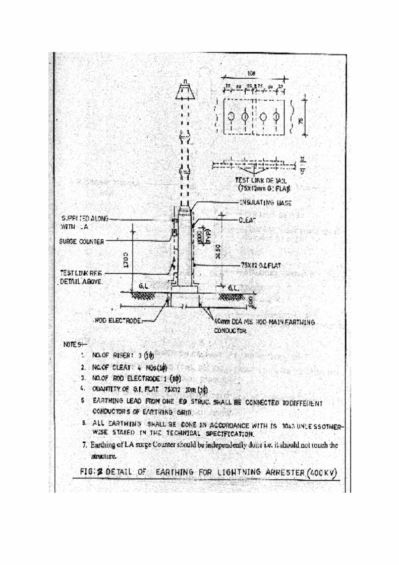


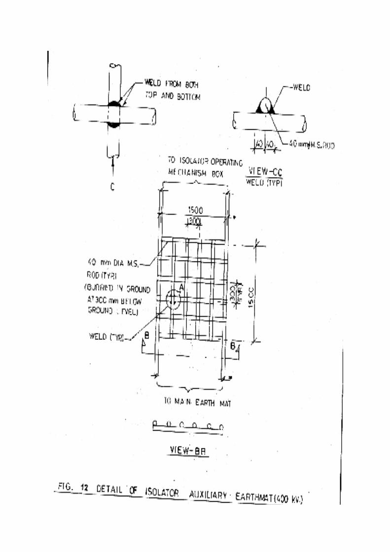


Table:2 Details of Apparatus /Structures to be earthed in Switchyard
Sl. No. Apparatus Parts to beEarthed
Method of connection
1. Support of bushing
insulators, Lightning
Arrester, fuse, etc.
Device flange or
base plate
Earth terminal of
each pole of 3
phase Surge
Arrester
Connect the earthing bolt of the
device to station earthing system.
In the absence of earthing bolt or in
case of connection to non-
conducting structures, connect
device fastening bolts to earth
When the device is mounted on a
steel structure, weld the structure,
mounting the device flange; each
supporting structure of apparatus to
earthing mesh via separate
conductor2. Cabinets of control and
relay panels
Frameworks of
switchgear and
cabinets
Weld the framework of each
separately mounted board and
cabinet minimum at two points to
the earth conductor of earthing
system.3. High-voltage Circuit
Breakers
Operating
mechanism,
frame
Connect the earthing bolt on the
frame and to operating mechanism
of CB to earthing system4. Isolator Isolator base
(frame),
operating
mechanism
bedplate.
Weld the isolator base frame,
connect it to the bolt on operating
mechanism base plate and station
earth.
Provide an auxiliary earth mat of
600 mm x 600 mm of earth
conductors in the ground near the
earth switch and connect the both.5. Surge Arrester Lower earth
point
To be directly connected to the
earth mat.

6. Potential
Transformer/CVT
CVT tank. LV
neutral, LV
winding phase
lead (if
stipulated by the
designers)
Connect the transformer earthing
bolt to earthing system.
Connect LV neutral of phase lead
to case with flexible copper
conductor.7. Current Transformer Secondary
winding and me
tal case
Connect secondary winding to
earthing bolt on transformer case
with a flexible copper conductor,
the case being earthed in the same
way as support insulators.8. Power transformer Transformer
tank
Connect the earthing bolt on
transformer tank to station earth.
Connect the Neutral directly to two
dedicated earth pits.9. Fencing Alternate
Fencing portions
GS earth flat connects the fencing
to earth mat.10. Water tanks Lightning rods
provided over
the top of water
tank
GS earth flat connects the lightning
rods to earth mat.
11. Cable trays & supports Cable trays and
support
GS flat running near trays is welded
at a spacing of 750 mm and
connected to earth mat at about 30
m distance.12. Shunt Reactor Tank Same as in transformer. NGR is
also connected to two earth pits.
3.8 Jointing Back to contents page
i)Earthing connections with equipment earthing pads are bolted type. Two bolts are
provided for making each connection. Equipment bolted connections, after being
checked and tested are painted with anti-corrosive paint/compound of specified
material.

ii)Resistance of Joint should not be more than the resistance of the equivalent length
of the conductor.
iii)All ground connections are made by electric arc welding. All welded joints are
allowed to cool down gradually to atmospheric temperature before putting any load
on it. Artificial cooling is not allowed.
iv)Each earthing lead from the neutral of the power transformer/reactor is directly
connected to two pipe electrodes in treated earth pit (as per IS) which in turn, are
buried in Cement Concrete pit with a cast iron cover hinged to a cast iron frame to
have an access to the joints. All accessories associated with transformer/reactor like
cooling banks, radiators etc. are connected to the earthing grid at minimum two
points.
v)Earthing terminals of each lightning arrester & Capacitor Voltage Transformer is
directly connected to rod earth electrode which in turn is connected to station
earthing grid.
3.9 Measurement of Earth Resistance Back to contents page
Three electrode methods is used for measuring the earth resistance in
switchyard (Fig. 14). To measure the earth resistance both C1 and P1
terminals of megger could be connected to a spike that is driven in
ground and connected to earth mat whereas terminals P2 and C2 are
connected to the equidistant spikes driven in ground (not connected to
earth mat). The value of of R could be read in the scale with the
rotation of the handle of megger or press of a button. This will give the
value of earth resistance. The value as far as possible should be below
1 ohm. In case this value is high water should be sprinkled in the
earthing pits for improvement of earth resistance.


DO’S DON’TS&
SPECIAL PRECAUTIONS

3.10 Do’s Don’ts and Special PrecautionsBack to contents page
i) Metallic conduits should not be used as earth continuity conductor.
ii) Wherever earthing conductor crosses or runs along metallic
structures such as gas, water, steam conduits, etc. and steel
reinforcement in concrete it should be bonded to the same.
iii) Flexible earthing connectors should be provided for the moving
parts.
iv) Steel to copper connections should be brazed type and treated to
prevent moisture ingression.
v) Sheath and armour of single core power cables should be earthed
at switchgear end and equipment side.
vi) Contact surface of earthing pads for jointing free from scale, paint,
enamel, grease, rust or dirt.
vii) Earthing conductors or leads along their run on cable trench ladder,
columns, beams, walls etc. should be supported by suitable
welding/cleating at intervals of 750 mm/ as specified.
viii)Light poles, junction boxes on the poles, cable and cable
boxes/glands, lockout switches etc. are connected to the earthing
conductor running alongwith the supply cable which inturn is
connected to earthing grid conductor at a minimum two points
whether specifically shown or not
ix) Earthing conductor is generally buried 2000 mm outside the
switchyard fence. All the gates and every alternate post of the
fence is be connected to earthing grid.
x) Meggar used for measuring soil resistivity should be calibrated with
great accuracy. In case if an accurately calibrated meggar is not
available, 2 or 3 different meggars should be used to take same set
of readings.
xi) The earth resistivity should be taken in dry weather condition.
xii) For transformer & shunt reactor earthing, earth pits of 3-4 m depth
below the ground with 40 mm dia GI pipe & specified quantity of salt
and coke should be provided.

xiii)The earth resistance should also be measured after completion of
laying of earth mat and earth electrodes by the same 4 electrode
methods for complete system, individual earth pits & earth rod
electrodes.
xiv)The measured value of combined earth resistance should not be
more than 0.5 ohm.
xv) For earth electrodes and individual earth pits, this value can be upto
1 ohm.
xvi)In case these values are not being achieved water should be
poured in earth pits to bring the earth resistance within the specified
range.

CHECK FORMAT

3.11 Check Format Back to contents page
1. Proper unloading arrangement has been made at site
(Preferably with crane) to unload the material.
Yes/No
2. All items have been checked with the packing list, MICC,
Challans, GR etc.
Yes/No
3. After unloading the visual inspection of the materials has
been carried out along with the erection contractor.
Yes/No
4. Earthing material has been checked for dimensions and
quality .
Yes/No
5. The galvanization of steel (where GI steel is to be used) is
proper.
Yes/No
6. Earthing conductor is buried at least 600 mm below finished
ground level/ at specified level.
Yes/No
7. Earthing Conductor crossing the road is laid 300 mm below
the road or at greater depth depending on the site
conditions
Yes/No
8. Earthing conductor in outdoor areas is buried at least 600
mm below furnished ground level.
Yes/No
9. Earth grid has been extended beyond 2000 mm from the
switchyard fencing towards outside.
Yes/No
10 Earthing pads have been provided for the apparatus /
equipments at accessible position.
Yes/No
11 All steel/RCC columns, metallic stairs are connected to
nearby earthing grid conductor by two earthing leads.
Yes/No
12 Metallic pipes, conducts and cable tray sections for cable
installations are bonded & then connected to earthing
conductor at regular interval
Yes/No
13 Earthing of Lighting fixtures, receptacles, switches, junction
boxes lighting conduit has been done by a separate
earthing conductor.
Yes/No
14 Railway tracks within switchyard area has been earthed at a
spacing of 30m/specified distance and also at both the
ends.
Yes/No

15 Cable trays have been connected to earthing flat of 50 mm
x 6 mm/ specified sized earthing flat.
Yes/No
16 This earth flat is earthed at about 30m distance. Yes/No17 Bolted conditions of earthing with the equipments have
been checked and tested before painting with anti corrosive
paint.
Yes/No
18 For transformer and shunt reactor earthing, earth pits of 3-4
m depth with specified sized GI pipe & specified quantity of
salt and coke have been provided.
Yes/No
19 Sheath & armour for single core power cable have been
earthed at switchgear end.
Yes/No
20 All accessories in transformer and reactor like radiators
tank, cooling banks etc. are connected to the earthing grid
at minimum two points.
Yes/No
21 Megger used for measuring earth resistivity has been
calibrated with great accuracy
Yes/No
22 Earth resistance has been measured after laying the
earthmat.
Yes/No
23 4 electrode method has been applied to measure the earth
resistance
Yes/No
24 Measured value of earth resistance is within specified range Yes/No25 In case the values are not within the specified limit, water
has been poured in earth pits to bring the earth resistance
within the specified range
Yes/No
CHAPTER-4SWITCHYARD STRUCTURES

___________________________________________________________________________CHAPTER
FOUR___________________________________________________________________________
SWITCHYARD STRUCTURESBack to contents page
4.0 Introduction
Back to contents page
Two types of structures are used in switchyard erection. These are
lattice type and pipe type structures. With both these type of structures,
supply of other components like washers, fasteners, foundation bolts
and other bolts & nuts is also linked up. Efforts should be made such
that a proper co-ordination is made in procuring these supplies and
structures so that erection work is not delayed due to non availability of
one or the other item. Various aspects right from the scope of work to
the erection of structures are described below.
4.1 Structure works in Substation Switchyard
Back to contents page
The scope of structural work in switchyard generally includes receipt,
handling, storage and erection of all lattice/pipe structures, lightning
masts, beams as shown in structural arrangement drawings and lattice
support for gantry and various equipments like CT, CVT, LAs etc. The
structure supports also include the cap and base plates, stiffeners,
clamps, foundation bolts mounting stool and bolts, fixtures for
supporting operating mechanism boxes, control cabinet etc. It also
includes the fabrication, supply, painting, erection of angle supports
and embedding in cable trenches as per cable trench designs and
layout, no. plates, phase plates and danger plates.
4.2 Receipt of Material & Inspection
Back to contents page
After receipt of all the materials at site, it should be inspected jointly
with the erection agency. This inspection is required to check the
materials received for their quantity, quality, correctness and
identification marks as per the delivery challan/ packing list etc. One
should go for checking the following :-
i) Despatch documents such as RR, LR, GR, MICC, Gate Pass,
Packing List etc.
ii) Quantity of materials received with the delivery challan, packing
list, BOQ and any shortages should be recorded.
iii) Identification marks should be checked from the MICC.
iv) Any physical damage should be brought to the notice of
supplier.
4.3 Storage
Back to contents page
i) The erection agency is allowed to store the angle/pipe material
near the place where tower gantries are to be installed. All
angles and pipes are to be stacked properly in such a way that
retrieving of required materials is easy.
ii) Maintenance of proper stock registers by the erection agency is
to be checked regularly by duly counter signing the registers.
iii) Bolts/nuts, spring washers, pack washers (in bags) should be
stored in the allocated room/building meant for storage with the
proper tags depicting the size, quantity, code no., supplier name
etc.

iv) In case the store building is not ready, the material may be kept
tents with adequate security.
4.4 Erection
Back to contents page
4.4.1 Erection of Gantry & Lattice Structures
Back to contents page
i) The erection should be carried out as per the specified technical
instructions and approved drawings.
ii) Tolerances are established in the approved manufacture drawings
or as stipulated in the technical specifications. Necessary care
should be exercised in handling to avoid the distortion of structures,
the marring of finish or bending of tower members.
iii) The erection work is carried out manually (by built up or piece meal
method) using ginpoles/derricks. However, crane can be used for
this purpose.
iv) The members are kept on ground serially according to erection
sequence.
v) The erection progress from the bottom upwards.
vi) The cross braces of the first section which are already assembled
on the ground are raised one by one as a unit and bolted to the
already erected corner leg angles.
vii) For assembling the second section of the towers, gin poles are
placed one each on the top of the diagonally opposite corner legs.
These two poles are used for raising parts of second sections.
viii)This process is continued till the complete tower in gantry is
erected.

ix) The lattice structure are used for various equipment erection in the
switchyard like circuit breaker, current transformer, CVT and surge
arrester.
x) Proper care in horizontal levelling of these lattice structure is taken
by using water level/spirit level. Even dumpy level/theodolyte may
also be used for good accuracy.
xi) To maintain the proper level necessary shims are inserted in pipe
works.
xii) The beam erection work of tower is carried out at the ground by
assembling various members preferably in two parts.
xiii)The assembled beam is lifted either by crane or by chain pulley
block. Even winch machines can also be used for this purpose.
xiv)The assembled beam is lifted slowly and carefully.
xv) One side of the beam is tightened first with the gantry structure on
one side. For finer adjustments winch machines can be used. This
side of assembled beam is fixed to the tower by proper sized bolts,
nuts & washers.
xvi)All the support structure for various equipments should be levelled
horizontally with water/spirit levels.
4.4.2 Erection of Pipe Structure
Back to contents page
i) The pipe structure are placed on the foundation bolts preferably by
cranes.
ii) During erection the top level of the pipe structure should be
maintained horizontal.

iii) This can be checked with the spirit level and shims can be used to
fill up the gap and to maintain the proper horizontal level.
iv) Necessary care is taken during pipe structure erection so that no
damage is caused to the threads of the foundation bolts.
v) The persons doing erection of pipe structure should use the safety
measures like helmets and safety belts etc.
4.3 Lightning Masts
Back to contents page
Lightning masts are the highest angle iron structures in the switchyard.
These are designed in the switchyard keeping in view the approved
switchyard bays. The erection procedure of Lightning Masts is similar
to that of tower and gantries.

DO’S DON’TS&
SPECIAL PRECAUTIONS

4.4 Do’s, Don’ts and Special Precautions
Back to contents page
During the erection of gantries/lattice structures/pipes following points
should be kept in mind.
i) As the supplies of lattice structure, washers, bolts and nuts, pipes
etc. is in the scope of different agencies, a co-ordinated follow up
should be maintained with the suppliers to the deliveries of these
items as per schedule. This will help in avoiding delays of erection
works due to non availability of one of these items.
ii) The lattice members, pipes etc. should be checked as per the BOQ
at site. The shortage or missed members in supplies should be
taken up with the suppliers rigorously. The erection work should be
started only after the structures are complete memberwise.
iii) Cranes should be used preferably for erection of pipe structure in
the switchyard.
iv) All safety procedures for erection work like use of safety helmets,
safety belts, use of guy wires etc. should be strictly adhered to
during structure erection works in the switchyard.
v) All the net/bolts should be tightened properly after the completion of
structure erection.
vi) Punching of bolts should be done.
vii) Any bend members and pipes should not be allowed and
straightaway rejected during supply stage.
viii)No hammering of members should be allowed to match the holes
during erection work.

ix) 2-3 threads of bolts should be exposed after tightening the nuts for
punching purpose.
x) Proper sized/bolts/nuts and pack washers should be used in
erection.
xi) After the completion of tower erection, proper tightening is to be
done. Before carrying out the final punching it must be ensured that
proper sized spring washers are provided.
xii) During erection, it should be seen that brazings should be properly
erected i.e., outer face of the member should always be at top so
that water does not stager on the members (water gate). Also,
members should not be over tensioned while carrying out the
erection.
xiii)Proper lifting arrangement of 4-5 MT capacity should be used
during erection works.
xiv)Proper sized spanners (box and ring type) as well as DE spanners
should be used.
xv) Poly-propylene ropes of 18/20/25 mm dia of about 100 m/as per
requirement length each may be used. The ropes should be
checked before use so as to avoid any breakage during works.
xvi)Steel rope of 3/8” dia of required length should be used with winch
machine.
xvii)D-shackles of 2 to 20 MT of different sizes should be used.
xviii)Single sheave and double sheave pulleys should not be less than
5 MT capacity. These should be checked for their smooth rotation
and locked during use on works.

xix)The verticality of different lattice structures should not be less than
the specified tolerance of 1 in 360.
xx) Proper punching of bolts/nuts is to be done on the various
structures.

CHECK FORMAT

4.5 Check Format
Back to contents page
1. All items have been checked with the packing list, MICC,
Challans GR etc.
Yes/No
2. After unloading the visual inspection of the angles/members
has been carried out for any bend/ damage.
Yes/No
3. All the members have been stacked properly in store. Yes/No4. Angles have been checked for size/dimensions, galvanization
and bend etc.
Yes/No
5. Required quantities of washers, fasteners, foundation bolts &
other bolts/nuts are available before starting the structure
erection at site.
Yes/No
6. All pipes have been checked and found straight w.o. any bends
or damage.
Yes/No
7. Bolts/nuts/spring, pack washers are stored in the closed room
(in bags).
Yes/No
8. Proper tags depicting the size, quantity code no. and supplier
name etc. have been written/inscripted on the tags tied on the
bags.
Yes/No
9. During structure erection proper safety measures like helmets,
safety bolts, ropes etc. are being used by the working
personnel.
Yes/No
10. All lattice members are available (as per drawings) before start
of erection.
Yes/No
11. Proper care in horizontal levelling of lattice structure for
equipments is taken by using water/spirit level.
Yes/No
12. To maintain proper level, shims have been inserted in pipe
works.
Yes/No

13. Assembled beam (of gantry structure) is being lifted with crane
for erection with proper safety.
Yes/No
14. Tightening and punching of bolts has been done properly. Yes/No15. Hammering of members has been disallowed during erection at
site.
Yes/No
16. 2-3 threads of bolts are exposed out after tightening the nuts for
punching purpose.
Yes/No
17. Proper sized bolts/nuts and pack washers are used in tower
erections.
Yes/No
18. Verticality of tower is within the safe tolerance of 1 in 360. Yes/No

CHAPTER-5BUSPOST INSULATORS & BUSBARS
___________________________________________________________________________
CHAPTER FIVE
___________________________________________________________________________
BUS POST INSULATORS & BUS BARSBack to contents page
5.0 Introduction Back to contents page
The substation busbars can be broadly classified in the following three
categories:
i) Outdoor Rigid Tubular Busbars
ii) Outdoor flexible ACSR aluminium alloy busbars
iii) Indoor busbars
The busbars are designed to carry certain normal current continuously.
The cross-section of conductors is designed on the basis of rated
normal current and permissible temperature rise. The value of cross
section so obtained is verified for temperature rise under short-time
short-circuit current.
The busbar conductors are supported on post insulators or strain
insulators. The insulators experience electro-dynamic forces during
short circuit currents. These forces are maximum at the instant of peak
of first major current loop. These forces produce bending moment on
separated insulators. The spacing between adjacent insulators is
decided on the basis of bending moment per metre and strength of
insulators.
5.1 Steps in Busbar Design Back to contents page
The busbar design is carried out in the following steps:
i) Choice of cross-section of conductor based on required normal
current, given ambient temperature and specified permissible
temperature rise.
ii) Calculation of temperature rise under short time current to see that
it is in safe limits.

iii) Calculation of electro-dynamic forces per metre for given short
circuit current.
iv) Calculation of choice of support insulators on the basis of bending
moment withstand value.
v) Calculation of span of support insulators on the basis of the force,
bending strength of insulators and factor of safety.
vi) Design of insulator system, phase to phase clearance, phase to
ground clearance and creepage.
vii) Design of support structures.
viii)Design of clamps and connectors, flexible joints.
5.2 Forms of Busbars Back to contents page
Busbars of Outdoor Switchyard are in the following forms:
ACSR conductors supported at each end on strain insulators.
Tubular Aluminium Conductors supported on post insulators
made of porcelain. These are either welded to get extended
lengths.
Busbars for Indoor Switchgear are in the form of aluminium or
copper flats. These are supported on epoxy cast insulators.
5.2.1 ACSR Back to contents page
ACSR conductor to be used for busbars is supported on insulators. As
most of the equipments can be installed below the flexible bus, land
requirements are also less. The cost of this scheme is lower due to
less no. of support structures.5.2.2 Aluminium
Back to contents page
Aluminium is used for busbars in indoor and outdoor switchgear.
Aluminium and aluminium castings (5 to 12% silicon) are used in
busbar. Aluminium is used in the form of strips /rectangular bars for
busbar application. While using aluminium for busbars, the difficulties
arise due to the following aspects:
i) Higher resistivity, hence associated problems of temperature rise.
ii) Lower tensile strength than copper.
iii) Lower thermal conductivity than copper.

iv) Higher coefficient of linear expansion than copper.
v) Higher joint resistance and associated problems about joining.
vi) Special welding techniques are necessary.
5.3 Configuration of Busbars in Outdoor Substation Back to contents page
The conductors of a busbars systems in an outdoor substation are of
the following two types:
i) Rigid aluminium tubular bus conductors supported on post
insulators
ii) Flexible ACSR supported on strain insulators. The conductors of
three phases of each bus are placed in horizontal configuration.
Table 1: Comparison between Rigid Bus System and Flexible Bus System
Feature Rigid Bus System Flexible Bus SystemCost Higher because of higher
conductor cost, post insulator
cost
Lower
Land Area
requirement
Larger Lower. Most of the
equipment installed below
the flexible busNumber of support
structures
- More numbers
- Simple
- Amount of steel lesser
- Less numbers
- Complex
5.4 Receipt and Inspection of Material at site Back to contents page
i) The items should be checked with the packing list, MICC, Challans
GR etc.
ii) In case of any discrepancy from the above documents/LOA the
same may be intimated to the manufacturer at the earliest.
iii) Any type of damage to the panels during transportation or any
missing items should also be brought to the notice of the panel
supplier.
iv) All materials and packages are to be carefully opened and verified
for damages and shortages, if any. These shortcomings have to be

properly intimated to the manufacturer as well as to the Insurance
authorities as the case may be.
v) Handling of large crates should be handled by crane carefully.
vi) All items should be stored on ramps/platforms, free from water
logging.
vii) BPIs are to be stored separately to avoid breakages.
5.5 Bus Post Insulators Back to contents page
Post type consist of a porcelain part permanently secured in a metal
base to be mounted on the supporting structures.
They are capable of being mounted upright. They are designed to
withstand any shocks to which they may be subjected to by the
operation of the associated equipment.
Porcelain used is homogeneous, free from lamination, cavities and
other flaws or imperfections that might affect the mechanical or
dielectric quality and thoroughly vitrified, tough and impervious to
moisture. Glazing of the porcelain is of uniform brown in colour, free
from blisters, burrs and other similar defects.
The insulator have alternate long and short sheds with aerodynamic
profile.
The design of the insulators should be such that stresses due to
expansion and contraction in any part of the insulator should not
lead to deterioration in Bus Post insulators
i) Every bolt should be provided with a steel washer under the nut
so that part of the threaded portion of the bolts is within the
thickness of the parts bolted together.
ii) Flat washer should be circular of a diameter 2.5 times that of
bolt and of suitable thickness. Where bolt heads/nuts bear upon
the levelled surfaces they are provided with square tapered
washers of suitable thickness to afford a seating square with the
axis of the bolt.
iii) All bolts and nuts should be made up of steel with well formed
hexagonal heads forged from the solid and hot dip galvanised.
The nuts should be good fit on the bolts and two clear threads

should show through the nut when it has been finally tightened
up.
5.5.1 Technical Parameters of typical Bus Post Insulators are Back to contents page
a) Type Solid core Solid core
b) Voltage class (kV) 420 245
c) Dry and wet one minute 680 460
power frequency withstand
voltage, Kv (rms)
d) Dry lightning impulse + 1425 + 1050
withstand voltagee) Wet switching surge + 1050 -
withstand voltage (kVp)
f) Max. radio interference 1000 1000
voltage (in microvolts)
at voltage of 305 kV (rms)
and 156 (rms) for 400 kV &
220 kV respectively
between phase to ground.
g) Corona extinction voltage 320 (Min.) 156 (Min.)
(kV rms)
h) Total minimum cantilever 800 800
strength (Kg)
i) Minimum torsional moment As per IEC-273
j) Total height of insulator (mm) 3650 2300
k) P.C.D
Top (mm) 127 127
Bottom (mm) 300 254
l) No. of bolts
Top 4 4
Bottom 8 8
m) Diameter of bolt/holes (mm)
Top M16 M16
Bottom dia 18 18
n) Pollution level as per Heavy(III) Heavy(III)

IEC-815
o) Minimum total creepage 10500 6125
distance for Heavy
Pollution (mm)
5.6 Erection of Aluminium Bus Bar Back to contents page
i) Before erection of the tube, it is to be checked for any scratches. If
any scratches are observed, they are to be repaired by means of
smooth file and emery paper.
ii) As Aluminium tube is soft material it is to be handled carefully to
avoid damages and scratches.
iii) The tube can be erected by means of crane or by means of a
derrick.
iv) Only polypropylene ropes are to be used to tie the tube while lifting.
v) After erection of the Aluminium tube it is to be checked that it rests
on all the BPI clamps (rigid/sliding/expansion) properly. If not,
necessary adjustments may be made by providing shims between
the clamp and the BPI.
vi) During erection of the tube care should be taken such that the tube
should be in perfect straight line and perfect level. The BPI clamps
suitable for Aluminium tube (rigid/sliding/expansion types) are
erected as per the erection key diagram.
5.6.1 Bending Procedure of Aluminium Tube During Erection: Back to contents page
Following bending procedure should be adopted during bending of the
Aluminium tube while bus bar erection
i) Wherever required the tube is bent suitably into a Z shape.
ii) Suitable tube bending machine is to be made use of.
iii) The tube bend should not be bent more than 45o.
iv) To ensure the circular cross section of the tube at the place of
bending the tube should be filled with smooth sand, well compacted
throughout the length of the tube and the ends should be plugged..
v) Care should be taken such that the tube is in one plane only even
after bending.
5.6.2 Welding of Aluminium Tube:

Back to contents page
i) Aluminium tube welding is done at erection site only by a qualified
and approved welder.
ii) Tube ends to be welded are cut neatly and precisely in shape.
iii) Both the tubes to be welded are kept in a plane and in the same
axis.
iv) Plane of the cut edge is to be exactly perpendicular to the plane
of longitudinal section of the tube.
v) The edge is to be made by grinding to the shape.
vi) Tube centring spacer is inserted in between them.
vii) Suitable welding sleeves of specified length for the above tube,
specially supplied for the purpose of tube welding is kept within
the tube, equally distributed in length among the tubes.
viii) After putting the pieces and welding sleeve in position 12 mm dia
holes are to be drilled at 100 mm intervals.
ix) Aluminium rods of specified length and dia with one end counter
shunk are inserted through these holes.
x) To accommodate the counter shunk aluminium rod the counter
shunk shape is drilled in the Aluminium Tube only.
xi) After positioning the tubes, welding sleeve and the Aluminium
rods in position the welding is to be taken up.
xii) The counter shunk Aluminium rods also are to be welded to the
tube.
xiii) Milli volt drop tests for testing the joints should be performed in
the field.
xiv) All other tests as given in the FQP should also be performed.
xv) If any of the joints are not successful in the test, those joints are
to be re-done.
5.7 Welding Procedure and Welder’s Qualifications Back to contents page
The erection contractor is supposed to get the Welding Procedure and
Welder’s /Welding Operator’s Qualifications approved from the
Corporate QA deptt. (in the enclosed proforma at Annexure-I and
Annexure-II) before commencement of the Aluminium welding of the
bus at site.


DO’S DON’TS&
SPECIAL PRECAUTIONS

5.8 Do’s, Don’ts and Special PrecautionsBack to contents page
i)In Aluminium tube the welding joint should not be at the centre. It
should be between support and 1/3 distance of the span.
ii)Dust free atmosphere is to be maintained at the place of welding.
iii)Check that proper alignment for complete aluminium tube is
achieved and verified before any welding is done.
iv)The welds in the Aluminium tube should be kept to the minimum and
there should not be more than one joint in the tube in any span length.
v)No inflammable material should be present around the work spot.
vi)While welding work is under progress, ensure the argon gas flow
along with the arc and also as long as the weld metal is red hot. This is
to prevent oxidation of the weld metal because of exposure to oxygen
in the atmosphere.
vii)The shed profile should meet requirements of IEC-88815 for the
specified pollution level.
viii) Welding of Aluminium tube at site should be done by adopting an
approved welding procedure and employing a qualified welder.
ix) Welders employed for Aluminium tube welding should be
experienced one in the field.
x)Corona bells should be provided wherever the bus extends beyond
the clamps and on free ends, for sealing the ends of the tubular
conductor against rain and moisture and to reduce the electrostatic
discharge loss at the end points.

5.9 Check Format Back to contents page
1. Proper unloading arrangement has been made at site (Preferably
with crane) to unload the packages.
Yes/No
2. All items have been checked with the packing list, MICC, Challans
GR etc.
Yes/No
3. After unloading the visual inspection of the packings has been
carried out along with the erection contractor and preferably with
the manufacturer of the equipment.
Yes/No
4. Any type of damage to the equipments/components during
transportation or any missing items has been brought to the
notice of the supplier.
Yes/No
5. Porcelain of BPI is free from lamination, cavities and other flaws
or imperfections.
Yes/No
6. Glazing of the Porcelain is uniform and free from blisters, burrs
and other defects.
Yes/No
7. Every bolt has been provided with a steel washer under the nut. Yes/No8. Packed washers of suitable size and thickness have been
provided.
Yes/No
9. Aluminium tube welding is being done by a qualified welder. Yes/No10. Aluminium tube welding is done as per approved welding
procedure.
Yes/No
11. Dust free atmosphere has been maintained at the place of
welding.
Yes/No
12. No inflammable material is present around the work spot Yes/No13. Care is taken so that not more than one joint is provided in one
span length
Yes/No
14. Aluminium tube has been checked for any scratches Yes/No15. In case of any scratches these have been repaired by mean of
smooth file and emery paper.
Yes/No
16. Only polypropylene rope is being used for Aluminium Tube
erection.
Yes/No
17. The tube is in the straight line and perfectly levelled. Yes/No18. BPI clamps for holding Aluminium tube have been erected as per
erection key diagram.
Yes/No
CHECK FORMAT

19. Suitable bending machine is used for bending purpose. Yes/No20. Care has been taken to maintain circular cross section of tube at
the place of bending by filling tube with smooth sand, well
compacted in the entire length & ends plugged.
Yes/No
21. Care has been taken so that pipe is in one plane after bending. Yes/No

Annexure - IQW-482 WELDING PROCEDURE SPECIFICATION (WPS)
SECTION IX, ASME-1986_____________________________________________________________
Joints (QW-402)
Joint Design :
Backing :
_____________________________________________________________
Base Metals (QW-403)
P.No. 23, Group No. SB221 to P No. 23, Group No. SB 221
Specification type and grade :
Pipe dia range :
Thickness Range :
_____________________________________________________________
Filler Metals (QW-404)
F. No. 23
Specification No. : (SFA) 5.10
AWS No. ER 4043
Size of filler metals :
_____________________________________________________________
_____________________________________________________________
Positions (QW-405)
Position of groove :
Welding progression :
_____________________________________________________________
Preheat (QW-406)
Preheat temperature min.
Interpass temperature max.
Preheat maintenance
_____________________________________________________________
Post weld heat treatment (QW-407)
Temperature range
Time range

____________________________________________________________
Gas (QW-408)
Shielding gas
Percent composition (mixture)
Flow rate
Gas backing
Trailing Shielding gas composition
_____________________________________________________________
_____________________________________________________________
Electrical characteristics
Current AC or DC
Amps (Range)
Tungston electrode size and type
Mode of metal transfer for GMAW
Electrode wire feed speed range
_____________________________________________________________
Technique (QW-410)
String or weave bead
Orifice or gas cup size
Initial and interpass cleaning
Method of back gauging
Oscillation
Contact tube to work distance
Multiple or single pass (per side)
Multiple or single electrode
Travel Speed (Range)
Peening
Other
_________________________________________________________________
WeldOthersLayer
Process Filler Class Metal dia Current
TypePolar
AmpRange
VoltageRange
Travel Speed
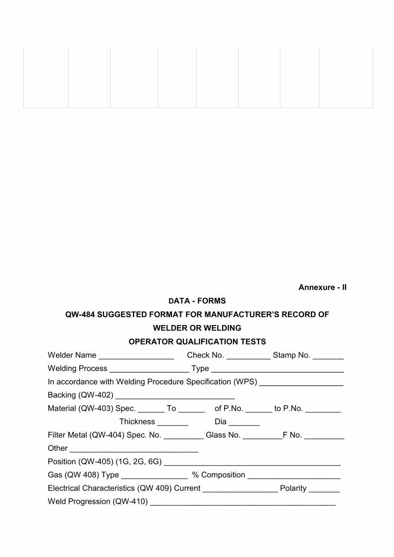
Annexure - IIDATA - FORMS
QW-484 SUGGESTED FORMAT FOR MANUFACTURER’S RECORD OFWELDER OR WELDING
OPERATOR QUALIFICATION TESTSWelder Name _________________ Check No. __________ Stamp No. _______
Welding Process __________________ Type ______________________________
In accordance with Welding Procedure Specification (WPS) ___________________
Backing (QW-402) ___________________________
Material (QW-403) Spec. ______ To ______ of P.No. ______ to P.No. ________
Thickness _______ Dia _______
Filter Metal (QW-404) Spec. No. _________ Glass No. _________F No. _________
Other _____________________________
Position (QW-405) (1G, 2G, 6G) ________________________________________
Gas (QW 408) Type _______________ % Composition _____________________
Electrical Characteristics (QW 409) Current _________________ Polarity _______
Weld Progression (QW-410) __________________________________________

Other _____________________________________________________
For Information Only
Filler Metal Diameter and Trade Name _________________________
Submerged Arc Flux Trade Name _________________________
Gas Metal Arc Welding Shield Gas Trade Name _______________________
Guided Bend Test Results QW-462.2(a). QW-463.2(a),QW-462.3(b)Type and Fig No.
Radiography Test for (QW 304 & QW-305)For alternative ____________ in above welds by radiography
Radiographic Results _________________________
Filler Weld Test Results _____________________62.4(a), QW-462 4(b)
Fracture Test (describe the location, nature _________________________
Length and Percent of _________________ inches %
Macro Test-Fusion
Appearance -Fillet Size________________________ in Convexity in or
Concavity _________ in ______________
Test conducted by ____________________ Laboratory - Test No. _______
We certify that the statements in this record are correct and that the test welds were
prepared, welded and tested required by the Code.)
NOTE: Any essential variables in addition to those above shall be recorded.

CHAPTER-6STRINGING SWITCHYARD
___________________________________________________________________________
CHAPTER SIX
___________________________________________________________________________
STRINGING IN SWITCHYARD
Back to contents page
6.0 Introduction
Back to contents page
In switchyard overhead stringing work is done between the gantries
and from the last tower on the lines to the first gantry structure. The
overhead stringing in 400 KV yard is done with twin ACSR moose
conductor. Erection of equipments can be started only after the
overhead stringing has been completed in the gantries of the
switchyard. The various outdoor equipments are connected with
overhead conductors by jumpers/droppers with suitable clamps.
Stringing is done manually in the switchyard, however, winch
machines may be used for final sag.
6.1 Pre- Stringing checks
Back to contents page
Though stringing work in switchyard is of small nature as compared to
a transmission line even then the site should take care of the following
before the stringing work starts at site.
i) Before starting and also during stringing works the condition of
conductor should be checked for any damage or scratches to the
aluminium strands of conductor.
ii) The glass/porcelain portion of insulators should be checked for any
cracks

iii) Insulators should be clean from dust or other foreign materials.
iv) Conductor should not be allowed to lie or rub on the ground during
paying/pulling.
v) Nuts and bolts of all gantry structure should be checked and the
tower members should be complete in all respect.
6.2 Stringing
Back to contents page
The process of manual stringing of moose conductor at site involves
the following steps :
i) Conductor is pulled between the gantries and strung on the
suspension on insulator strings.
ii) The final sagging is done by using winch machines. The winch
machines are connected to the leg of the towers/gantries.
iii) Final adjustment of conductor is done upto the desired point that
point by moving the conductor through winch machines and the
conductor is cut at the desired length.
iv) Dead end joint by compression machines is provided at the end of
the conductor with the dead end cone compressed with
compression machine.
v) Conductor is strung at the end with the double tension fitting.
vi) On suspension structure the conductor is strung through
suspension clamps.
vii) Spacers are provided between twin conductors after final sag is
completed.
6.3 T & P and Materials used for Stringing
Back to contents page

The following Tools and Plants and Line material is required while
stringing in substation switchyard.
Single sheave pulley (open type) - 4 Nos.
Double sheave pulley - 2 Nos.
Hydraulic/manual compression
machine of 100T capacity with die sets - 1 No.
Winch machine 10T capacity - 1 No.
Come along Clamp(Bolted/Automatic - 6 Nos.
Wire Cutter - 1 No.
Poly-propylene rope (25 mm dia) - 100 m or as
desired
D -Shackle - 8 nos.fs
Wire slings of required length - 16 mm dia
Spanners, round/flat files Screw driver, - 1 set
flat files, steel tape, Hecksaw frame each
& blades / as per reqmt.
ACSR moose conductor - As per
reqmt.
Single suspension fittings - - do
-
Double tension fittings - - do
-
120 kN porcelain/glass insulators
for suspension fitting - - do
-

160 kN porcelain/glass insulators
for tension fitting - -
do -
Spacers
(Bundle spaces and/or Rigid spacers) - -
do -

DO’S DON’TS&
SPECIAL PRECAUTIONS

6.4 Do’s Dont’s and Special Precautions
Back to contents page
i) Conductor during stringing should not be allowed to drag on
ground. For this purpose wooden planks or ground rollers should
be used to avoid any damage to the conductor.
ii) Insulator string should be pulled in such a way that it does not
drag/entangle with the tower members causing any damage.
iii) Adequate safety precautions should be taken by the personnel
working on the towers/ground. They should wear safety helmets
and use safety belts whole working on towers/structures. Workers
and supervisory staff working on ground should wear the safety
helmets.
iv) Conductor should be checked constantly as it is unwound from
conductor drum for any broken, damaged or loose strand. In case if
any major defect is noticed the defective conductor has to be
removed.
v) Marking of conductor should be done correctly after adjusting
length of tension fitting.
vi) Conductor should be cut at the marked point and dead end joint
be provided.
vii) Sag should be checked by sighting through the theodolite placed
on ground near the tower. Any mismatch should be corrected by
using sag adjustment plate in tension fitting.
viii)Immediate medical care should be provided to workmen met with
an accident. First Aid Box should be available at stringing site.
ix) Insulators should be completely cleaned with soft and clean cloth.
x) It should be verified that there is no crack or any other damage to
insulators.
xi) It is very important to ensure that ‘R’ clips in insulator caps are
fixed properly. This is a security measure to avoid disconnection of
insulator discs.
xii) Necessary precautions should be taken so that no damage to
insulators is caused during hoisting. In case of any damage, the
same needs to be replaced.
xiii)All hardware fittings should be provided as per approved drawings.
xiv)It should be verified that all nuts and bolts are tightened properly.
xv) It should be ensured that all the necessary security pins (split pins)
are fixed properly.
xvi)Conductor should be rejected in case it is found to contain any
broken, damaged or loose strands.
xvii)Proper arrangements should be made to avoid rubbing of
conductors on ground/hard surfaces by providing wooden planks.
xviii)Subconductors of each phase should be simultaneously tightened
by winch machine fixed on tower leg until the desired final sag is
achieved.
xix)Marking of conductor should be done correctly after adjusting
length of tension fittings.
xx) Conductor should be cut at the marked point and dead end joint be
provided with adequate compressive strength.
xxi)Spacers should be provided as per approved placement chart.
xxii)Length of jumper should be carefully checked such that it is in
parabolic shape and jumper drop is as per approved drawing.

Length of jumpers of sub-conductors of a bundle should be properly
checked so that jumper spacers lie in horizontal position as far as
possible.
xxiii)All nuts and bolts of jumper fittings should be properly tightened.
This is very essential to ensure tightness of jumpers to avoid hot
spot and melting in future.
xxiv)Jumper spacers should be provided as per technical specification
and approved drawings.
xxv)No damaged component of any hardware fitting should be used on
works.
xxvi)Sag mismatch should be within permissible limits.
xxvii)All fittings provided should be as per specification and approved
drawings. All necessary details like make, dimension, size and
specifications of these fittings should be recorded separately in
register for tractability in future.
xxviii)Jumpers/drops should be tightened properly. Live metal
clearance should be maintained as per specification.
xxix)Insulators should be cleaned with soft cloth. Glazing should be
proper and there should be no crack or white spot on its surface.
xxx)‘R’ Clips in insulators should be fitted properly.
xxxi) All Nuts/Bolts in fittings should be tightened properly.
xxxii)All components of fittings should be completely provided as per
approved drawings.
xxxiii)In case of Tension fitting dead end joint dimensions before and
after compression should be checked and recorded.
xxxiv)All components of spacers/jumper spacers should be provided as
per approved drawings.

6.5 Check Format
Back to contents page
1. Towers are tightened properly and all the members, Nut/Bolts
are complete in no. and size.
Yes/No
2. All Line materials, tested T & P, safety equipments and
relevant drawings are available for stringing.
Yes/No
3. Conductor is checked continuously during stringing in
switchyard. Damaged portion, if any, is removed.
Yes/No
4. Proper arrangements are made to avoid rubbing of conductor
on ground/hard surfaces.
Yes/No
5. Sag is measured correctly at prevailing temperature. Details
are recorded.
Yes/No
6. After measuring sag, marking/cutting of Earthwire/ conductor is
done correctly to fix dead end joint.
Yes/No
7. Conductor, insulators and other hardware fittings are available
at site before starting the overhead stringing.
Yes/No
8. Insulators and other hardware fittings have been cleaned
properly before erection
Yes/No
9. All fittings have been assembled at ground and all components
are OK.
Yes/No
10. All components of fittings have been checked up for
dimensions and make as per the manufacturer’s drawings
Yes/No
11. Insulators have been checked for any cracks/damage and care
has been taken that insulators are not broken during lifting.
Yes/No
12. Care has been taken so that conductor while pulling is not
damaged.
Yes/No
13. Proper sag and tension have been maintained as per the day
temperature and sag tension chart
Yes/No
CHECK FORMAT

14. Subconductors of each phase are being tightened
simultaneously by winch machine & to achieve the desired
sag.
Yes/No
15. All nuts & bolts of jumper fittings have been tightened properly. Yes/No16. Jumper spacers have been provided. Yes/No17. Spacers have been provided as per the spacer placement
chart.
Yes/No
18. Care has been taken to avoid any overtensioning. Yes/No19. R. Clips of the insulators in insulator string have been properly
provided.
Yes/No
20. In both suspension and double tension fitting the split pin have
been splitted properly.
Yes/No
21. Length of jumpers has been measured properly to give it a
parabolic shape.
Yes/No
22. In case of tension fitting dead end joint dimensions before &
after the compression are checked and recorded.
Yes/No
23. Jumpers are tightened properly. Live metal clearance have
been maintained as per specification.
Yes/No

CHAPTER-7SURGE ARRESTER

___________________________________________________________________CHAPTER
SEVEN
SURGE ARRESTERBack to contents page
7.0 Introduction Back to contents page
Surge Arrester is a device designed to protect electrical equipments
from high voltage surges and to limit the duration and amplitude of the
follow current. Surge arresters are used to protect Power System
Installations and equipments against lightning overvoltages also.
Generally arresters are connected in parallel with the equipment to be
protected, typically between phase and earth for three phase
installations.
The main element of a surge arrester is the ‘Non-Linear Resistor’, the
part of the arrester which offers a low resistance to the flow of
discharge current thus limiting the voltage across the arrester terminals
and high resistance to power frequency voltage, thus limiting the
magnitude of follow current.
There are 2 types of designs available for EHV Surge-Arrester. These
are Conventional gapped Surge-Arrester (Value Type) and Metal Oxide
Surge-Arrester.
7.1Conventional Gapped Lightning Arrester (Valve Type Arrester) Back to contents page
In a substation the Surge Arrester is connected between line and earth.
It is the first apparatus as seen from the overhead transmission line
entering in the switchyard. It consists of resistor elements in series with
gap elements offer non-linear resistance such that for normal
frequency power system voltages the resistance is high however, for
discharge currents the resistance is low. The gap units consist of air
gaps of appropriate length. During normal voltage4s the lightning


arrester does not conduct. When a surge-wave travelling along the
Overhead line comes to the arrester, the gap breaks down. The
resistance offered being low the surge is diverted to the earth. After a
few micro seconds the surge vanishes and normal power frequency
voltage is set up across the arrester. The resistance offered by
resistors to this voltage is very high. Therefore, are current reduces
and voltage across the gap is no more sufficient to maintain the arc.
Therefore, the current flowing to the earth is automatically interrupted
and normal condition is restored. The high voltage surge is discharged
to earth. Hence the insulation of equipment connected to the line is
protected.
7.2Metal Oxide Lightning Arresters Back to contents page
The metal oxide arresters without spark gaps consist of an active part
which is a highly non linear ceramic resistor made of essentially Zinc
Oxide. Fine Zinc Oxide crystals are surrounded by other metal oxides
(additives). Such microstructures render extreme non-linear
characteristics to these ceramic resistors.
In the operating characteristic of Surge Arrester the current axis is in
logarithmic scale. The current increases by 107 orders of magnitude
when the voltage across element doubles. This special characteristics
is the heart of protection technology in this type of Surge Arrester.
The lower linear part ‘A’ is temperature dependant and exhibits a
negative temperature coefficient. The arrester is designed in such a
way that the applied operating voltage gets located around point ‘O’.
This results in a continuous resistive curent of few micro amps flowing
through the resistor elements. Under over voltage condition, the
voltage increases and shifts operating pont momentarily for
overvoltage duration to point near ‘B’. This results in a resistive current
of few milli-Amperes flowing through the resistor elements. As soon as
the overvoltage disappears the operating point shifts back to ‘O’. In the
event of transient switching or lightning vervoltages, the operating point
will shift to portion ‘C’. For the transient of a few micro seconds it will
draw current in the range of 5/10 k Amps. In the event of very high
lightning current of the order of 40 to 100 k Amps peak, the operating

point will shift to portion ’D’. However, on expiry of transient of few milli
seconds the operating point will come back to point ‘O’.
Thus the operating point of these arresters is normally located at point
‘O’ called Maximum Continuous Operating Voltage (MCOV) and the
point ‘B’ of the Fig. (5) indicates approximately the rated voltage of
arrester. The arrester can stay at point ‘O’ i.e., MCOV, all long its life
but can stay at point ‘B’ (fault condition), i.e. Rated Voltage, for only 10
seconds (it is presumed that system breakers will operate to isolate the
fault within 2 seconds). The energy that gets dissipated, I.e. (I2R)
during continuous or overvoltage condition decides the size (dia) of
ZnO resistor element. These are classified as different classes
depending upon the energy handling capabilities. Higher class
corresponds to higher energy capability.
7.3 Packing, Transport, Handling And StorageBack to contents page
(i) Las are packed vertically on sturdy wooden case. For reasons of fragile
porcelain, care should be taken while unpacking, handling and installation
so as to avoid impact with hard surface.
(ii) Immediately on receipt, inspect the cases for signs of transhipment or
physical damages packings. In case of any damage matter should be
reported to insurance company as well as the manufacturer for guidance.
(iii) At site the Surge Arrester should e stored in the original packing case and it
should also be ensured that boxes are kept in the original vertical condition.
(iv) While taking out of the cases too, Arrester units should be placed in upright
position, the porcelain sheds facing down.
(v) As LAs are assembled in controlled condition, no attempt should be made at
site to open or repair the arrester without consultation of the manufacturer.
(vi) It is recommended to use nylon ropes for handling the arrester at site.


7.4 Installation
Back to contents page
i) LAs are mounted on sturdy structure.
(ii) Mounting plate of structure top should be regular and horizontal.
(iii) Check the level with a Spirit Level before mounting.
(iv) Clean the porcelain surface of insulators.
(v) Measure resistance preferably by 5 kV meggar. The insulation
resistance should be more than 1000 M Ohms.
7.5 Installation of Single Unit Arrester
Back to contents page
(i) Fix base plate with 4 bolts (if it was not already fixed) to LA bottom.
(ii) Base insulators should be placed loosely on the mounting plate of structure.
(iii) Fix the Surge Counter mounting bracket alongwith one of the base insulator
to the structure.
(iv) Lift the arrester vertically up as shown in figure.
(v) Lower the Arrester unit and use base insulator stud \ bolt to guide it in place.
(vi) Fix the Arrester in position.
(vii) Fix Surge Counter on the Surge Counter Bracket.
(viii) Connect the stud at the back of Surge Counter to base plate by the
connecting link.
(ix) When surge counter is not in use, base plate should be positively connected
to earth.
7.6 Installation of Multi-Stack Arrester
Back to contents page
(i) Fix base plate to LA bottom (if not fixed already)
(ii) Loosen and remove 4 bolts from top of the top units.

(iii) Fix the corona ring to the top of the top unit / middle unit using
the same bolts.
(iv) Loosen and remove 4 bolts from top of the bottom unit (& Middle
unit in case of 3 stack LAs).
(v) Lift the Top unit and engage 4 studs at the bottom.
(vi) Lower the top unit to the top of bottom unit (or middle unit in
case of 3 stack LAs) by guiding the stud and keeping
intermediate plate in between.
(vii) Fix the units in place. (In case of 3 stack LAs fix the top & middle
unit to bottom unit as described above.)
(viii) Keep the base insulator loosely on the top of structure.
(ix) Lift the LA (interconnected) and lower the structure top by
guiding through the base insulator bolts.
(x) Fix the Surge Counter mounting bracket with one of the bolts.
(xi) Surge monitor is connected to the main earth mat in the
substation.
(xii) Ensure that structure is earthed with the earth mat in the
substation.
(xiii) Fix the LA and secure in position by the 4 bolts.
(xiv) Fix surge counter on the bracket and connect the stud at the
back of the surge counter to the base plate.
(xv) When surge counter is not in use, base plate should be
positively connected to earth.
(xvi) Connection of jumper to the LA, CVT can be made through T
clamp or P G clamp or directly connected to the overhead
conductor.

DO’S DON’TS&
SPECIAL PRECAUTIONS

7.7 Do’s, Don’ts & Special Precautions
Back to contents page
(i) Slack span stringing from dead end tower to the gantry should
be completed before taking up of the erection of line Arrester.
(ii) Surge monitors of each phase is to be checked for any damage.
(iii) The IR value of each stack is to be measured.
(iv) Use of flexible copper strips between the bushings and earth
strips should be preferred.
(v) Proper care to prevent any damage to the surge bushing should
be taken.
(vi) Insulators should be cleaned before erection at site.
(vii) Terminal connectors should be tightened to proper torque.
(viii) Surge monitor has been connected to main earth mat.

CHECK FORMAT

7.8 Check Format
Back to contents page
1. Proper unloading arrangement has been made at site
(Preferably with crane to unload the packages.
Yes/No
2. All items have been checked with the packing list, MICC,
Challans GR etc.
Yes/No
3. After unloading the visual inspection of the packings has been
carried out along with the erection contractor and preferably
with the manufacturer of the equipment.
Yes/No
4. In case of any damage the matter has been reported to the
manufacturer (or insurance agency if required)
Yes/No
5. Slack span stringing from dead end tower to the gantry has
been completed before taking up of the erection of line LA.
Yes/No
6. IR value of each stack has been measured Yes/No7. Insulators have been cleaned before erection at site Yes/No8. Mounting plate of structure top is regular and horizontall. Yes/No9. Level has been checked with a Spirit Level before mounting. Yes/No10. Terminal connectors have been tightened to proper torque. Yes/No11. When surge counter is not in use, base plate has been
positively connected to earth.
Yes/No
12. Surge Monitor has been earthed by connecting it to main earth
mat.
Yes/No

___________________________________________________________________
CHAPTER EIGHT
___________________________________________________________________
ISOLATORBack to contents page
8.0 Introduction
Back to contents page
Isolators are disconnecting switches which are used for disconnecting
the circuit under no load conditions. They are installed in such a way
that a part of substation circuit can be isolated from other live parts for
the purpose of maintenance. Isolators play an important role in
maintenance of a substation. An isolator can be opened only after
opening the circuit-breaker. An isolator should be closed before
closing the circuit breaker. Opening and closing of a current carrying
circuit is performed by a circuit-breaker. An isolator does not have any
specified current breaking capacity or current making capacity. In some
cases isolators are used for breaking charging current of transmission
lines.
420 kV Centre Break Isolators are designed for independent single
pole operation or three pole electrically/mechanically ganged operation.
Single or Double Earth Switches, as required, can be fitted to them.
These isolators can be operated either manually or by motor. These
isolators are supplied in components and are assembled at site.
8.1 Construction features
Back to contents page
CHAPTER-8ISOLATOR

420 KV Centre Break Isolator comprises of the following:
i) Support Structure
ii) Base Assembly
iii) Insulator Stack
iv) Male and Female contacts Assembly
v) Operating Mechanism (Main & Earth)
vi) Down Operating Pipe (Main & Earth)
vii) Tandem Pipe (Main & Earth)
viii) Earth Switch Assembly
8.1.1 Support Structure
Back to contents page
i) Support Structure are made out of tube.
ii) They have the arrangement to fix over the foundation for fixing the
Base Assembly on the top of the structure and Operating
Mechanism Box (Main & Earth)
iii) Earthing strip fixing arrangement is also provided along with.
iv) These structures are designed to withstand all forces like short
circuit force, wind force and wind load etc.
v) Isolator structures are supplied in hot dip galvanised condition
8.1.2 Base Assembly
Back to contents page
For every 3 pole switch there are 2 types of bases.
i) Base Assembly with drive arrangement and interlocking
arrangement (if the switch is with earth). Other base is without
drive arrangement

ii) Stoppers are provided in both ends to control the travel of Moving
Blades in both close and open position of isolator.
iii) Complete base assembly and other components are duly
galvanised
iv) Base assemblies are supplied with
a) Inter Post coupling pipe assembled and aligned condition
b) Inter-Lock arrangement in set condition
c) Levers are assembled with pins, friction washers, brass
washers and split pins.
8.1.3 Insulator Assembly
Back to contents page
Insulators are selected to suit the basic insulation level, minimum
creepage and minimum bending load to suit the equipment design
requirement.
8.1.4 Male and Female Contacts Assembly
Back to contents page
i) In male and female contacts assembly the current carrying parts
are made up of Aluminium tubes
ii) The male and female contacts (reverse loop design) are made of
Electrolytic Copper with Silver Plating.
iii) The Connecting Stem is made out of electrolytic copper with Tin
Plating/Aluminium.
iv) The current transfer part that connects the Aluminium housing and
stem is made out of Copper with Tin plating and assembled inside
the Housing.
8.2 Operating Mechanism

Back to contents page
Two types of operating mechanisms are available in isolator.
8.2.1 Geared motor operating mechanism
Back to contents page
This consists of a reduction gear assembly which is driven by spur
gear fitted with 3-phase induction motor through pinion gear,
necessary overload protection, control switches for local/remote
operation, limit switches and mechanical stoppers. The mechanism
can be operated manually in case of failure of supply.
8.2.2 Manual operating mechanism
Back to contents page
i) Both the mechanisms are housed in a cabinet made of sheet steel.
Auxiliary switches having silver-plated contacts and positive wiping
action with adequate number of NO, NC and long wipe contacts are
provided.
ii) Front door of the mechanism box is provided with good quality
neoprene gaskets, which, on compression, when the door is closed,
ensures high degree of protection against polluted atmosphere. All
the boxes are metal treated before being taken up for painting.
Suitable terminal blocks made of highly non-inflammable
thermosetting plastic are provided for terminating control and
auxiliary wiring.
8.2.3 Earth Switch Assembly
Back to contents page
i) The vertical lift earth employs a turn and thrust movement by
initially rotating through 90o and subsequently moving upwards by
approximately 100 mm.

ii) The earthing switches can be actuated on a individual pole basis or
3 poles can be coupled and actuated by a single drive.
iii) Moving Blade of earth switch is made out of aluminium tube and
contacts are made out of copper with silver plating.
iv) Mounting Base and all other parts are galvanised.
8.3 Receipt , Handling and Storage
Back to contents page
i) All packages are to be carefully opened and verified for damages
and shortages, if any. These shortcomings have to be properly
intimated to the manufacturer as well as to the Insurance authorities
as the case may be.
ii) Handling of large crates should be handled by crane carefully.
iii) All items should be stored on ramps/platforms, free from water
logging.
iv) All items should be stored in upright position only.
v) Insulators are to be stored separately to avoid breakage’s.
8.4 Erection/Installations
Back to contents page
8.4.1 Structures
Back to contents page
i) Refer the site layout drawings and compare with equipment
General Assembly Drawing.
ii) Identify the structures according to the General Assembly Drawing
iii) Structure assembly is lifted and fixed over the plinth (Without
damaging the foundation bolts)
iv) Assemble washer, spring washer and nuts in all foundation bolts.

v) Check for level at the top of the structure in both directions by using
spirit levels. If required give shims below the base plate of structure
and tighten the nuts.
vi) All other structures should be assembled in similar way
8.4.2 Base Assembly
Back to contents page
i) Identify the Base Assembly from Equipment General Assembly
drawing.
ii) Lift the base assembly by using proper ropes and place it over the
relevant structure
iii) After keeping it over the base without removing the rope align it to
the mounting hole of base and top plate of structure and fix the
bolts and nuts and remove the rope.
iv) Check for level of flanges in both direction by using spirit level.
v) If necessary add shims below the leg of the base and align it.
vi) Tighten all the Bolts.
vii) Repeat the installation process for other two poles also.
viii)Ensure the Centre line of same pole and centre line of other
phases are aligned
ix) After completing the installation keep all the base assemblies in
open position
8.4.3 Insulators
Back to contents page
i) The top middle and bottom units of Insulators should be identified
by using Insulator Drawing.

ii) The bottom and middle units are assembled together by using
proper bolts and nuts. Lift the Insulator stack by using proper
hook and placed over the base assembly by ensuring the top 4
holes position.
iii) Without removing the hook align the holes and fix all bolts.
iv) The level of top surface of insulator should be checked by spirit
level/plumb and if necessary the shims should be inserted below
the bottom flange of the insulator or/and between two insulator unit
flanges .
v) Now rotate the shaft assembly & check for the rotation of insulator
& its eccentricity.
vi) The same procedure is to be repeated for the other side of same
pole also
vii) In the same way the top unit of insulator and middle unit are
installed On both sides.
8.4.4 Contacts Assembly (Male and Female Assembly)
Back to contents page
i) Identify the Assembly as per General Assembly Drawing
ii) Keep the Insulator corona ring on top of the Insulator
iii) Lift the Male Assembly by using proper sized rope and place it
over the insulator above corona ring.
iv) Without removing the rope align the holes and fix the screws.
v) Repeat the similar process for female assembly.
vi) Rotate the bearing shaft assembly and check for alignment of
Contacts assembly for horizontal alignment. Shims should be
inserted between the mounting flange of Assembly and top of
the insulator at relevant side. Similarly for vertical alignment
necessary shims should be inserted between insulator flange and
top of shaft assembly flange.
vii) If the entry is not smooth, loosen the contacts Mounting screws
and push the contacts forward or backward to get free entry.
viii) After achieving the entry check for centre line of Male and Female
in both directions.
ix) Now moving part should be rotated 2 to 3 times to ensure the
proper alignment
x) The Corona ring assembly should be identified for male and
female unit and connected properly to it.
xi) Moving part should be operated two to three times for checking
the free movement and also check that the contact corona ring
are not fouling each other
8.4.5 Connecting Disconnector
Back to contents page
i) Manually set mechanism and disconnector to be connected into
fully OPEN position (Arrow mark on top of mechanism cabinet
indicates the 'open' and 'close' positions).
ii) If mechanical interlock keys are fitted, it will be necessary to
obtain the relevant keys to make mechanism operational.
iii) Align the fixing hole and bolt them together to achieve desired
tightness.
iv) Ensure that the mounting channel on the drive and the structure
are matching.

v) Level the box by placing the spirit level on output shaft flange in
two directions.
vi) Provide shim wherever required.
vii) Check for centre line and verticality between torque bearing
flange and drive flange with a plumb.
viii) Introduce Universal Coupling as called for in the General
Arrangement Drawing.
ix) Measure exact height between torque bearing flange and top of
universal flange.
x) Cut the operating pipe with the specified clearance to facilitate
smooth entry.
xi) Weld the vernier flange properly keeping the flange
perpendicular to the centreline of the pipe. Level and bolt the
same. The drive is now ready for operation. Mounting angles of
mechanism to structure are slotted to provide horizontal
adjustment. Adjust the mechanism so that the vertical drive
tube rotates TRUE.
xii) Cabling (internal/external) be completed as per schematic
drawing. Ensure that all electrical interlocks are wired properly.
xiii) Before energising the circuitry, interlock wiring and control wiring
should be checked by multimeter (as per schematic drawings)
8.4.6 Controls for Electrical Operating Equipment
Back to contents page
A hinged panel on the right hand side of the cabinet carries the
electrical controls for operation of the mechanism. Controls for normal

operation are mounted on the front of the panel and are accessible
immediately the outer cabinet door is opened
These comprise :
i) Local OPEN and CLOSE Control Switch
ii) In case of individual pole drives the master control cabinet will
have push buttons for operating/closing also.
iii) Local/Remote Selector Switch
iv) Heater/Light Switch
8.5 Closing Operation of Isolator
Back to contents page
i) Ensure all castle keys are in position.
ii) Once the associated circuit breaker is open, closing contact will
energise the interlock thereby making availability of supply at the
local/remote selector switch.
iii) Set the electrical remote selector to local position as required and
then press push button for closing, thereby causing the closing
contactor to pick up.
iv) The hold on contact of closing contactor will now be closed there-
by retaining the supply after the push button is released.
v) Simultaneously contacts of closing contactor will close, thereby
supply to motor is made available.
vi) Ensure motor direction is towards closing. Otherwise alter the
phase sequence at motor terminal box.
vii) The isolator will start to close, and at the end of the closing
operation, limit switch for closing will open then de-energising the
closing contactor.

viii) The circuit is now de-energised and the closing operation is
completed.
ix) Car should be taken to prevent the mal-functioning. Contact
closing (CC) of the closing contactor will isolate the opening
circuit, once closing contactor is energised.
8.6 Tandem Pipe Assembly
Back to contents page
i) After single pole trial with motor keep that pole in closed
condition
ii) Fix other two poles also in closed condition (set the stopper
screws)
iii) Measure the distance between the lever of two adjacent poles
('R' & 'Y')
iv) Check and set the Tandem, pipe length on the floor itself
v) Lift the Tandem pipe by using proper rope and fix one side first
by using suitable anti friction washers, brass washers and split
pins.
vi) Fix other side in the same manner.
vii) Operate the operating mechanism and check for proper closing
and opening of both poles. If required do minor adjustments in
Tandem Pipe by length by using adjusting screw. Then finally
lock the adjusting screws by check nut.
viii) Repeat this process for the other poles ('Y' & 'B')
8.7 Earth Switch Assembly
Back to contents page

i) Identify the Assembly to fix the fixed contact assembly through
General Arrangement Drawing
ii) Take the Earth fixed contact assembly and fix it with the Hamper
Assembly by using proper sized Bolts as per General Assembly
Drawings. The above assembly can be carried out before
installing the Hamper Assembly over the insulator.
iii) Lift the Earth Blade Assembly by using rope and fix it with base
assembly using the middle set of mounting holes to hold the
assembly in place.
iv) Attach counter balance weights in pendulum arm at suitable hole
and check the position of Earth Switch which should be parallel to
ground.
v) Manually move earthing blade towards closing position .To adjust
add shims at the back of the mounting plate to tilt the earthing
blade in required direction.
vi) Continue to move earthing blade towards closing and observe
that the contact fingers come into the fixed contact. A small
adjustment to twist the contact fingers is possible by shimming
mounting plate.
vii) Continue to close earthing switch until contacts are fully engaged
i.e. when the insulated stop of the earthing blade comes to rest
without straining against fixed contact.
viii) Tighten all fixing bolts and keep the earth switch in closed
position.

DO’S DON’TS&
SPECIAL PRECAUTIONS

8.8 Do’s, Don’ts and Special Precautions
Back to contents page
i) Before the isolator is put into operation, the motor is to be
meggered and the contacts are cleaned.
ii) The mechanism box always is to be kept free from moisture.
Hence, space heaters are provided in the mechanism box.
iii) Also rubber beading should be kept in good condition.
iv) Cable glands should be properly fitted at the entry of the cables
and extra holes are plugged properly to avoid hazards.
v) For transportation, individual base and bearing pole assemblies &
the male and female contact arms should be packed separately.
The Insulators and drive boxes should also be packed separately.
vi) The bolts and nuts required for mounting the base to the structure
and the Insulators to the base are packed separately as loose
items, while all the other hardware (bolts & nuts) are fitted in their
respective places. Care should be taken that these are removed
only at the time of mounting to respective assemblies.
vii) All the assembles should be stored well preferably in a covered
area to avoid any damage/pilferage during storage.
8.8.1 Adjustment in drive/assembly erection
Back to contents page
i) Manual
a) By use of emergency handle, operate the coupled disconnector
and observe whether it is fully OPEN or CLOSE at each end of
its operating cycle

b) If isolator does not CLOSE fully remove clamping bolts and turn
mechanism slightly towards /OPEN and retighten bolts proceed
turning isolator towards CLOSED.
c) Repeat until satisfactory operation is obtained.
ii) Electrical
a) Make electrical connections by referring to contract diagram of
connections of incoming supply.
b) Do not attempt to operate the disconnector under power at this
stage.
c) When selector switch is fitted set it to LOCAL
d) When AC Motor is fitted manually set mechanism to mid position.
e) Operate control Switch and at the same time observe whether the
mechanism rotates towards the selected position
f) If it rotates in opposite direction to that selected stop motor
immediately by switching off power supply.
g) If necessary reverse the to phases of motor supply.
iii) Open and Close Push Buttons
The Control Push Buttons determine the direction of travel of the
isolator. When a cycle is initiated by switching to the appropriate
position the isolator will open or close. Once the mechanism has
received a signal the push button can be released. The
mechanism will complete the operation and will not respond to
further signals until it has completed its operation. An indicator,
shows the isolator position either OPEN or CLOSE outside the
cabinet at the base of the output shaft.
iv) Selector Switch

When the selector switch is set to LOCAL, operation of the
mechanism will be governed by the controls in the cabinet.
Setting the selector switch to REMOTE transfers controls of the
mechanism to remote control point.
v) Heater and Heater Switch
An anti-condensation heater is fitted in the bottom of the cabinet.
It should be switched on at all times, ensuring that the
temperature inside the cabinet exceeds the temperature
outside. The heated air leaves the cabinet by way of breather
around the output shaft and cool air is sucked in. A switch is
mounted on the front of the control panel for the control of the
heater through a thermostat.
vi) Open and Close Contactors
These contactors are mounted side by side on the rear of the
electrical control panel. They directly control the reversing
operation of the motor. Further contacts are used for electrically
interlocking the contactors, providing a sealing circuit across the
'OPEN' and 'CLOSE' Push Buttons.
vii) Auxiliary Switches
Silver plated contacts with a positive wiping action are used
giving reliable making of low current signalling circuits under
adverse climatic conditions.
viii) Fuse Links
Fuses for the control and heater circuits are mounted on the
control panel. Connections to these are made in the same
manner as connections to terminal blocks. The fuse wire is

routed through the top of the carrier. The current ratings of fuse-
links are shown on the schematic diagram drawing.
For opening the Isolator a similar sequence of operation will be
executed by pressing the push button for opening.
ix) Manual Operation
The mechanism may be operated manually in the event of a
motor power failure with the help of manual operating handle.

CHECK FORMAT

8.9 Check Format
Back to contents page
1. Proper unloading arrangement has been made at site
(Preferably with crane) to unload the packages.
Yes/No
2. All items have been checked with the packing list, MICC,
Challans GR etc.
Yes/No
3. After unloading the visual inspection of the packings has been
carried out along with the erection contractor and preferably
with the manufacturer of the equipment.
Yes/No
4. Any type of damage to the equipments/components during
transportation or any missing items has been brought to the
notice of the panel supplier.
Yes/No
5. Site where isolator is to be erected is ready before the starting
of erection work.
Yes/No
6. Level of the structure assembly has been checked during
erection using spirit level
Yes/No
7. Site where isolator is to be erected is ready before the starting
of erection work.
Yes/No
8. Level of the top surface of isolators has been checked during
erection, alignment & level of equipment
Yes/No
9. Centre line of all the poles in different phases are aligned. Yes/No10. Centre line alignment of male & female assembly has been
checked
Yes/No
11. Before fitting, the crane rings have been identified for male and
female assembly
Yes/No
12. Moving parts have been operated 2-3 times for checking the
free movement
Yes/No
13. The rotation of motor is in right direction Yes/No14. In case it is in opposite direction the same has been corrected
by altering of the phase sequence of the motor terminal.
Yes/No

15. Lifting of tandem pipe assembly is with proper size rope Yes/No16. During erection movement of earthing blade has been checked Yes/No17. Contact fingers of earthing blade and moving towards the fixed
contact
Yes/No
18. All fixing bolts have been tightened to keep the earth switch in
proper close/open position
Yes/No

CHAPTER-9CURRENT TRANSFORMER

___________________________________________________________________________
CHAPTER NINE
___________________________________________________________________________
CURRENT TRANSFORMERBack to contents page
9.0 Introduction
Back to contents page
Current transformers are used for reducing/stepping down ac current
from higher value to lower value for measuring /protection /control. CTs
have low VA rating.
Rated characteristics of CTs used for High Voltage metering/ protection
are given below:
i) Rated primary current
ii) Rated short time current (primary)
iii) Rated secondary current
iv) Rating exciting current
v) Rated burden
vi) Current error or ratio error
vii) Phase angle error
viii)Composite error
ix) Accuracy class
i)Over current factor
ii)Insulation level (primary)
9.1 Construction Features
Back to contents page

Construction-wise the Current Transformer may be of following two
types:
Hair Pin design or dead tank type and Top dome design or Dead Tank
design. In the hairpin design the primary conductor enters from the top
of insulators and passed through the tank. The secondary core is
wound on the primary inside the tank. The body of tank is earthed to
the switchyard earthing. Current Transformers of WSI, BHEL, ABB are
of this type. In the other top dome design the Primary conductor goes
straight in the dome shaped tank at the top. Secondary winding is
wound against it. As the tank body is always live this design is known
as the live tank design. Current Transformers of CGL, RK are of this
design. As the head is heavy, more care is required while lifting and
alignment of the CT.
The Current Transformer essentially consists of primary and secondary
coils and core. The core is constructed in the form of rings. The
secondary winding is wound uniformly over the insulated ring cores.
The secondary terminals are brought out through a terminal board into
the terminal box. From terminal board the connections are given to the
terminal blocks. The control cables are connected to the terminal
blocks.
The primary winding consists of Copper strips/Aluminium pipe (with
single turn) over which high quality insulation paper is wound.
Aluminium foil is wrapped at suitable intervals over the insulation paper
to get a constant voltage gradient along the arcing distance of the
porcelain insulator. The insulated primary passes through the
porcelain insulator and taken out through 4 nos. terminal bushings
(each rated for 1200 A) fixed to the wall of the expansion chamber.
The respective terminal bushings are shorted internally. The primary
conductor has sufficient cross sectional area to meet the continuous
and specified short-time current ratings.
The outer surfaces of ferrous parts are given light grey enamel paint to
shade over rust inhibitive coat of ready mixed zinc chrome primer.
Steel surfaces coming in contact with transformer oil are given a coat
of oil resisting varnish. Galvanised bolts and nuts are used as
fasteners. All welded and gasket joints are subjected to leak tests.
9.1 Hermetic Sealing
Back to contents page
The current transformer is subjected to heat and vacuum cycle in a
drying chamber to extract the moisture from the insulation paper. After
drying and oil impregnation under vacuum, the current transformer is
hermetically sealed with dry Nitrogen gas above oil. When the oil
expands or contracts due to temperature variations, the Nitrogen gas in
the chamber undergoes change in pressure. Depending on the
pressure and temperature, a part of Nitrogen gas in the chamber
undergoes change in pressure and a part of Nitrogen gas will be
absorbed by oil. The volume of expansion chamber and the gas
pressure at the time of initial filling are adjusted so that the gas
pressure will be less than + 0.5g/cm2 at 75oC and above -0.2 kg/cm2
at 0oC. A drain valve is provided at the bottom of lower tank. Some
CTs come with rubber/teflon/steel bellows to take care of temperature
variations. Such CTs are not filled with Nitrogen gas.
9.2 Transportation, Unpacking & Inspection

Back to contents page
i) The 400 kV current transformer is dispatched in the horizontal
position (with the oil level gauge side at the top) fixed to a
transportation frame in wooden crates whereas 220 kV CT is
positioned vertically in packing.
ii) Special oil sealing arrangement is provided in the expansion
chamber to prevent contact of Nitrogen gas with paper insulation
when the current transformer is in the horizontal position.
iii) For unloading /loading the crates, crane should be used in store
and switchyard. However, truck should be used for transporting
the CT from store to switchyard.
iv) CT at site should always be lifted from lifting brackets which are
provided on the base.
v) Unpacking of wooden crates should be done with particular care
so as not to damage the porcelain insulator and terminal
bushings.


vi) After receiving at site CT should be checked for any physical
defect.
vii) The name plate readings/rating of CT should confirm to
technical specification of our LOA.
viii) All the crates containing different parts of CT should be checked
with the store challans/MICC/Packing list etc.
ix) CT should be lifted by crane using chains/strings from the
indicated handling points on crates.
x) 400 kV CT is to be made vertical immediately on receipt at site
and kept in vertical position only.
9.4 Installation/Erection
Back to contents page
i) As the current transformer is dispatched in completely assembled
state, it can be installed directly after making it upright. It is to be
ensured that before commissioning, the porcelain insulator is clean
and free from all dust, grease and particles of packing material.
ii) Alignment of the support structure should be checked with
spirit/water level.
iii) Place the CT on duly levelled supporting structure by using a crane.


iv) Care should be taken such that primary polarity of erected CT is
correct and as per relevant drawing.
v) Fix the CT with four anchor bolts to the supporting structure.
vi) Now the crane can be removed after tightening the bolts & nuts.
vii) Provide proper earthing of transformer from the base of CT.
Earthing connection should be permanent.
viii) Lay the control cables from control room relay panels and
connect to CT marshalling box.
ix) Control cables should be laid in trays or in pipes.
x) Marshalling box of CT should also be earthed.
xi) Cabling work on secondary side should also be completed & its
IR valve be ascertained.
xii) Cable continuity should be checked after erection is completed.
xiii) Star point should be earthed properly.
xiv) Care should be taken during handling, lifting, loading or
unloading and erection no damage is done to CT insulator by
slings. Proper cushioning arrangement should be used for the
same.
xv) The receipt storage and erection should be done as per the
approved FQP.
xvi) The threaded fasteners should be clean & tight and missing or
broken fasteners should be replaced.
xvii) It should be ensured that all the times the oil in CT is at the
specified level and there is no leakage of oil.

xviii) The primary injection test of CT should be carried out as per the
prescribed procedure.
xix) Any secondary core of CT that is not being put in service should
be short circuited.
xx) Polarity of all secondary cores should be checked.

DO’S DON’TS&
SPECIAL PRECAUTIONS

9.5 Do’s Don’ts & Special Precautions
Back to contents page
i) In order to keep the unit hermetically sealed, the flanged joints with
gaskets in between should not be tampered with. The cover of the
secondary terminal box alone needs be opened for giving
connections to control cables.
ii) Since the current transformer is hermetically sealed and uses no
material harmful to oil, there is no necessity for extraction of
samples of oil for analysis or for reconditioning of oil. Check for
Nitrogen gas pressure is also not required. If oil level is below the
red mark it indicates leak and should be investigated.
iii) In case of heavy pollution deposits due to surrounding atmospheric
conditions, periodic external cleaning of porcelain insulator and
cleaning/painting of other exposed surfaces can be carried out (as
per the specific instruction of the manufacturer)
iv) Precautions should be taken not to keep open secondary circuit
when current is flowing in the primary as this may cause
overheating of core and breakdown of the insulation due to high
voltage developed across the secondary terminals.
v) The lower tank should be earthed in a positive and permanent
manner before commissioning.
vi) The CTs are dispatched with secondary terminals short circuited.
Care should be taken so that the shot circuiting links at the
terminals are not disturbed.
vii) For lifting the CTs at site one should look for proper handling points
for using slings and read the specific manufacturer’s instruction to
avoid any mishap.
viii)Weight of the CT should be read from the name
plates/specifications & lifting tackles of ample capacity should be
used.
ix) Crates of CT should be lifted without jerks or vibrations and placed
at the desired place without dropping or hard hitting on ground.

CHECK FORMAT

9.6 Check Format
Back to contents page
1. Proper unloading arrangement has been made at site
(Preferably with crane) to unload the packages.
Yes/No
2. All items have been checked with the packing list, MICC,
Challans, GR etc.
Yes/No
3. After unloading the visual inspection of the packings has been
carried out along with the erection contractor and preferably
with the manufacturer of the panels.
Yes/No
4. Any type of damage to the packing during transportation or
any missing items has been brought to the notice of the
manufacturer.
Yes/No
5. The unpacking of CT has been done carefully to avoid any
damage to it.
Yes/No
6. Site where CT is to be erected is ready before the starting of
erection work.
Yes/No
7. It has been checked that there is no leakage of oil from CT Yes/No8. Cranes or other good quality lifting T&P is available at site to
transport/ CT from store to site and for erection
Yes/No
9. Care has been taken to avoid any damage to insulators
during lifting (by providing cushion of suitable material)
Yes/No
10. Oil level in CT has been checked Yes/No11. IR value of primary and secondary winding recorded &
satisfactory results are obtained
Yes/No
12. CT has been placed on the support structure very carefully
and all nuts have been tightened.
Yes/No
13. The structure/equipment has been levelled Yes/No14. The polarity of CT is correct Yes/No15. The table of CT has been earthed at two points Yes/No16. The marshalling has been checked for heating and lighting
arrangement
Yes/No

17. The cable work between C&R panel to marshalling box is
complete.
Yes/No
18. Continuity of all cables has been ascertained Yes/No19. Primary injection test of CT at relay terminal has been
performed as per prescribed procedure.
Yes/No
20. Secondary core of CT that is not in use has been short
circuited.
Yes/No
CHAPTER-10CAPACITIVE VOLTAGE TRANSFORMER

___________________________________________________________________________
CHAPTER TEN
___________________________________________________________________________
CAPACITIVE VOLTAGE TRANSFORMERBack to contents page
10.0 Introduction
Back to contents page
Capacitive voltage transformer can be effectively employed as a
potential source for metering, protection, carrier communication and
other vital functions of an electrical network.
In the case of EHV systems CVTs are always supplied in multi-unit
construction. The multi-unit construction enables ease of transportation
and storage, convenience in handling and erection etc.
10.1 Description & operating principle:
Back to contents page
The Capacitive Voltage Transformer comprises of a Capacitor Divider
along with its associated Electro-Magnetic Unit. The Divider provides
an accurate proportioned voltage, while the Electro-Magnetic Unit
transforms this voltage, both in magnitude and phase to convenient
levels suitable for metering and protection.
The Electro-Magnetic Unit (EMU) comprises of the following
components;
Compensating Reactor
Intermediate transformer
Damping device


The compensating reactor is used for tuning CVTs to the desired rate
frequency of 50 Hz. Since the CVT comprises of capacitors the compensating
reactor plays the role of nullifying the capacitive effect of reactance due to the
capacitance of the CVT.
The capacitor unit comprises of HV capacitor C1 & intermediate
voltage capacitor (C2). These capacitor consist of oil impregnated,
series connected capacitor elements; housed inside oil filled porcelain
insulators. Each capacitor unit is hermetically sealed.
i) Capacitor Units
It comprises of metallic bellows to compensate for volumetric
expansion of oil inside the Porcelain. In case of multi-unit stack all the
potential points are electrically connected and shields are provided to
overcome the effect of corona and RIV.
ii) Transformer
The voltage tapped from the intermediate point of the capacitor is fed
to the primary of the transformer through the choke. This tapped
voltage is stepped down by the intermediate voltage transformer to the
required rated secondary voltage.
Typical Transformer Ratings
In case of 400 kV/4000/6600 pf and 400 kV/8800 pf CVT the rating
of transformer may be
Table -1: Rating of Transformer
1. Rated primary voltage 22/3 or 20/3 kV rms (Primary of
intermediate voltage transformer)

2. Rated secondary voltage 110/3 V (across each secondary
winding)3. Total simultaneous burden 300 VA for 0.5 class accuracy4. Rated output burden and accuracy
class per winding
Winding 1 : 200 VA 3P
Winding 2 : 200 VA 3P
Winding 3 : 100 VA 0.5
The transformer is made up of CRGO laminations of core type design
over which primary and secondary windings are wound around the
laminations. The insulation between the core and the windings and
interturn insulation is done by means of paper.
iii) Details of capacitor divider unit :
The Capacitor divider unit is used acts as a
i) Coupling capacitor for carrier communication.
ii) Voltage divider for stepping down the voltage to a suitable
level.
This stepped down voltage is fed to the primary of the
transformer through a choke (compensating reactor) which is
housed inside the electromagnetic unit.
The Capacitive Divider normally comprises of capacitor
elements of cellulose paper dielectric with aluminium foil
electrode. These elements are identical and are connected in
series by using copper taps. Hence the voltage across each
element is identical. The reduction in voltage is achieved by
taking tap from one of the capacitor elements.
10.1 Packing and Transportation :
Back to contents page

i) All Capacitor Units or the Capacitive Voltage Transformer are
securely packed in wooden crates. The Electro-Magnetic Unit
forms an integral part with the capacitor unit. In the case of Multi-
Unit type, the bottom most capacitor unit is hermetically associated
with the Electro-Magnetic Unit. Each wooden crate is identified with
the corresponding serial number of the unit inside.
ii) Each Capacitor unit has one Name Plate designating the rating of
the unit. Position of the Unit in the complete assembly is also
indicated in the Unit Name Plate by incorporating Top Unit or
Middle Unit or Bottom Unit.
iii) Bottom-most unit of Multi-Unit stack has one Master Name Plate
fixed on to the Electro-Magnetic Unit and one unit Name plate fixed
on to the bottom flange.
iv) The transportation must be performed in vertical position only.
Transportation should be carried out as smoothly as possible
without undue jerks.
v) The unpacked parts of the device should also be moved in the
same vertical position as within the packing
10.3 Receiving
Back to contents page
While receiving the CVT the site should check :
i) That the right CVT has reached at the destination with regard to its
voltage and other rating particulars.
ii) Ensure that CVTs are not mislinked.

iii) Look for transit damage before proceeding with any unloading
operation. Where a doubt arises, apprise the insurance authority or
insist on open delivery from the Transport Carriers.
iv) Inspect for breakage’s. In case of the manufacturer should be
notified immediately.
v) During handling, ensure that the capacitor Unit is always its upright
vertical state.
10.4 Unloading :
Back to contents page
Before unloading the crate(s) of the CVT from the carrier or
transporting vehicle
i) Carefully observe the instructions on the wooden crates.
ii) It is important to look for sling or chain markings, supporting points
etc. and use them.
iii) Ensure that the Top and Bottom ends of the crates are in order.
iv) Make arrangements for unloading with derricks or cranes and with
associated hoisting facilities.
v) Unload the crates one by one, taking all precautions required for
fragile material.
vi) As all porcelains are fragile and are susceptible to breakage, avoid
knocks and jerks during handling.
vii) The base unit should be lifted with crane by means of lifting lugs
provided on the EMU cover. Otherwise there is danger of breaking
a porcelain bushing.
viii)For taking the capacitor unit out of packing, use lifting lugs provided
on top cover of capacitor.

ix) While unloading/unpacking, vibrations, shocks are to be avoided.
x) The separate capacitor unit must be short circuited by bare wire
between head & bottom flange until erection and connection are
completed.
10.5 Storage
Back to contents page
i) CVTs are dispatched with the terminals short circuited. Store
the Capacitor Voltage Transformers taking care that the short
circuiting at the terminals is not disturbed.
(ii) A free capacitive voltage transformer with its terminals not short
circuited picks up dangerous potentials which may cause
injuries to personnel.
iii) It is also to be ensured that the CVT should be kept always in
vertical position.
iv) When not in use keep the Capacitive Voltage Transformers away
from energised locations, water logged areas, marshy or humid
locations.
v) When CVT is to be stored, it should be put back into trapezoidal
crate/packing case.
If prior to the installation, the CVT is to be stored for longer
duration without usage, the following tests may be carried out
on the CVT.
a) Visual inspection as per approved drawing
b) Measurement of capacitance
10.6 Installation
Back to contents page

i) Before proceeding with the installation, keep all the units near
the erection site.
ii) Ensure that the Top, Middle and Bottom units are (if applicable)
properly identified as per their serial numbers indicated on the
name plates.
iii) Base unit is to be fixed on a supporting structure with bolts of
specified size.
iv) For fixing the base unit, 4 holes are provided on the bottom plate
of the EMU unit.
v) If, there is an upper capacitor unit then it is to be fixed with the
top flange of the lower unit with the help of studs, nuts and
washers
vi) For assembly of capacitor units which have antifog shads on the
porcelain or which have broaden sheds, the threaded studs
used for coupling have to be first held into the through holes of
the flanges, before the units are placed are above the other.
The assembly has to be done with utmost care, to prevent
damage to the porcelain sheds.
vii) For handling the base unit & upper capacitor during the erection
process, use of crane is necessary.
viii) The studs used for coupling the capacitor units have to be
tightened with the specified torque.
10.7 Connection
Back to contents page
i) The upper terminal of individual capacitor unit should be short
circuited to the base by basewire till all connections are

completed and unit is ready for commissioning care should be
taken to remove this bare wire prior to commissioning.
ii) The tank of CVT base of CC should be earthed properly at two
independent places
iii) In case of CVT if carrier frequency terminal is not to be used it
should be earthed on the steel tank.
iv) The line matching unit is to be connected between HF bushing
outdoor and earth if CVT is used for carrier coupling otherwise this
terminal is to be earthed.
v) Connection work in the secondary terminal box should be done
when HV terminal is earthed.
vi) The cables with large cross sections are inserted through the
bottom of the terminal box. The connections should correspond to
the circuit diagram on the inner side of terminal box.
vii) The earthing of secondary winding (s) must be done either in the
terminal box at the beginning or at the end of cable but not at the
both ends. It is preferable to earth the secondary terminal in
terminal box.
viii)However for open-delta connection protection scheme for earthing
of secondary winding should be referred.
ix) The quick acting fuses for each secondary windings are mounted in
the terminal box itself.
x) The secondary terminals must not be touched and the head of the
person attending this job should be below the level of the tank
cover.

xi) Only metering winding for monitoring equipment and protecting
winding for protective equipment should be selected.
xii) Unused secondary windings should be left open circuited and in no
case they should be shorted.
xiii)The tank should be earthed by means of copper conductor, the
cross section of which complies with the statutory regulations. One
end of the secondary winding should also be earthed.
xiv)After confirming the low voltage ratio, connect the HV terminal to
the line by terminal connector. While clamping the terminal
connector proper torque should be applied to ensure firm
connection.


xv) It should be ensured that the jumper is rightly connected to the
primary terminal of CVT.
xvi)Pre -Commissioning checks should be carried out as per the norms
of Corporate Operation Services Department.

DO’S DON’TS&
SPECIAL PRECAUTIONS

10.8 Do’s, Don’ts and Special Precautions
Back to contents page
i) In case of multiunit construction the capacitance of each divider is
to be measured separately. In case of bottom divider the same has
to be removed along with the bottom flange from the EMU tank.
ii) After removing the bottom divider from the EMU check for any loose
connection of EMU. This test may be carried out using the shearing
bridge.
iii) Measure the depth of the bellow.
iv) In case of any evidence of traces of oil do not energise the CVT.
v) Measurement of voltage ratio
vi) Apply a very low voltage say 230 V and measure the secondary
voltage across each winding. It should be matching the
specifications of the manufacturer.
vii) Carry out the meggering test on LV terminal of EMU by using 500 V
megger.
viii)The measured value should not be below 10 M ohms.
ix) Check the resistance of the damping resistors after disconnecting
the connecting leads from the secondary terminal studs.
x) The CVT should always remain in its upright position to safeguard
mechanical arrangement of the internal active parts.
10.8.1 Inspection before mounting
Back to contents page
i) Oil level in the tank is to be checked. The red line on the oil level
gauge indicates rated oil level at 20o C.

ii) Tightness of the tank and capacitor units is to be checked. All units
(oil level gauge, cover, oil drainage joints) should be checked for oil
levels.
iii) A leakage at the insulator indicates defect in transportation. In case
any leakage is detected, the unit should not be installed and
manufacturer to be contacted.
iv) Before the CVT is placed in position, check with a 500 V DC
Megger whether the internal connection to the primary and
secondary windings are intact and property connected.
v) CVT secondary winding should never be short circuited.
vi) While connecting the measuring instruments, protective relays to
the secondary terminal, ensure the load/burden on respective
secondary winding is not exceeded.
10.8.2 Defect/Damage
Back to contents page
i) If defect/damage is noticed, matter should be reported without any
delay to the manufacturer with full details like type, designation
and serial number of equipment, nature of defect/damage and exact
location of defect .
ii) When the device i.e CVT/CC consists of two or more than two units
it must be insisted that each upper unit is mounted up on
corresponding base unit.
iii) The units are calibrated at manufacturer’s works before they are
despatched. Therefore pay attention to date (manufacturing no,
from the last certificate) on the rating plate and on special plate at

top cover of the upper units. Upper units pertaining to different CVT
should not be assembled together.
iv) Corona shield in two halves are supplied loose in the same packing
case and it is to be fixed after mounting top units. In case of multi
unit CVT the unit with single capacitor stack is generally supplied
with Corona shields duly mounted.
v) Small repairs (defects on surfaces) may be done at site. Leakage
should be reported to the manufacturer with a statement of Item
No., Order No., date of commissioning and other specifications.
10.8.3 Minor Irregularities
Back to contents page
i) Should the insulator gaskets begin to leak slightly for instance,
tighten up the clamp holding the insulator in an attempt to stop the
leakage. The nuts should be tightened up successively by about
1/6 of a turn until they are all uniformly tight the maximum torque
being 70 kg-cm.
ii) Careless excessive or uneven tightening of the nuts may damage
the insulator If tightening up does not stop the leakage the matter
should be reported to the manufacturer.
iii) If a secondary bushing, is leaking try to stop the leakage by
tightening the nuts slightly. If the leakage does not stop, matter
should be reported to manufacturer.
10.8.4 Erection
Back to contents page
During installation the studs used for coupling capacitor should be
tightened by applying torque of specified strength.
i) During erection process of CVT at site preferably the crane should
be used for handling the different units.
iii) It is to be ensured that capacitor unit with same serial numbers
are coupled during erection of CVT with 2 or more capacitor
units.
iv) Upper as well as the lower capacitor unit has to be short
circuited & connected to earth, until the erection and
commissioning work is being done on the CVT. (The capacitor
get charged by the electrical fields in the vicinity and they keep
these changes for a long time, which can be dangerous to
human life. Hence the shorting of capacitor unit is necessary).
v) No screwed joint of the capacitor units and base units should be
unscrewed.

CHECK FORMAT

10.9 Check Format
Back to contents page
1. Different CVT units have been transported and stored in
vertical position
Yes/No
2. Physical verification of CVT done as per specifications,
challans, BOQ, MICC etc.
Yes/No
3. Unloading of CVT done using crane Yes/No4. CVT checked for any physical damage, discrepancy etc. Yes/No5. Oil level in CVT is OK Yes/No6. In case of any damage/discrepancy same has been reported to
supplier/insurance agency.
Yes/No
7. Proper lifting arrangement for different CVT items at site being
provided
Yes/No
8. Mounting bolts of base plate have been tightened properly Yes/No9. Various parts of CVT joined and tightened to the designed
torque
Yes/No
10. HF terminal of unutilised CVT is properly earthed Yes/No11. Care has been taken to avoid short circuiting of CVT
secondary winding
Yes/No
12. Crane is used for handling the capacitor units Yes/No13.Different erection activities performed as per approved FQP. Yes/No14. Fuses in CVT marshalling box are OK Yes/No15. Cable laying activity is complete from relays to marshalling box Yes/No16. Proper earthing of CVT tank has been done Yes/No17. Terminals have been properly tightened. Yes/No

CHAPTER-11POWER LINE CARRIER
COMMUNICATION

___________________________________________________________________________
CHAPTER ELEVEN
___________________________________________________________________________
POWER LINE CARRIER COMMUNICATIONBack to contents page
11.0 Introduction
Back to contents page
In the modern Power System network for stable operation of large
network a reliable communication is required. Difficulties in obtaining
reliable and cost effective communication medium limit the choice of
the Communication medium to power line carrier (PLC). The same
power lines carrying the Electrical Energy are utilised for
Communication.
11.1 PLC System
Back to contents page
PLC system are principally used to carry information in the form of
speech or the form of data representing Telemetering, Telecontrol,
Teleindicator and Teleprotection. The signals are transmitted by means
of H.F. carrier Trans/Receiver, the carrier frequency may be anywhere
between 30 kHZ and 500 kHZ the information wave band is 300 HZ
to 3.4 kHZ.
Speech Band = 300 HZ to 2 kHZ
Data Band = 2 kHZ to 3.4 Khz
11.2 Coupling Equipment
Back to contents page

To enable the Power Lines to be employed for Communication
purposes some from of coupling equipment is required which will
permit the injection of Higher frequency carrier signals without undue
loss and at the same time de- couple the Communication equipment
from the power unit.
11.3 Coupling Equipment Description
Back to contents page
Essentially Coupling Equipment Comprises of the following
i) Capacitive Voltage Transformer (CVT)
Coupling capacitor (8800 pF to 22000 pF) of suitable voltage
withstanding capability is inserted between the carrier
equipment and HV Line which isolates the H.F. equipment
connected on LV side from HV side. The coupling capacitor
passes the H.F. frequency signals and blocks the power
frequency signals towards carrier section.
ii) Wave Trap/Line Trap
The coil is rated to carry full line power frequency current; the
rating of choke is 0.1 to 1.0 mili Henry. Tuning pot in parallel
with coil is used as tuning device to block the carrier frequency
entering the substation. Line trap unit is inserted between
busbar and connection of coupling capacitor to the line. It is
parallel tuned circuit comprising L and C. It has a low impedance
(less than 0.1 ohm) to 50 Hz and high impedance to carrier
frequencies. This unit prevents the flow of carrier signal towards
substation and at the same time offers negligible impedance to
the power frequency current.

The line traps are connected in series with the high voltage lines
on the station side. These are designed for the following ratings:
Normal power frequency current
Short-time short-circuit current
Basic insulation level characterised by the normal power
frequency voltage, lightning impulse withstand voltage and
switching impulse withstand voltage.
11.4 Constructional Features
Back to contents page
The line trap unit comprises of the following main parts:
Main coil
Tuning Unit
Lightning Arrester.
Corona ring for 400 kV Line Trap (this is generally supplied loose, it
should be fitted before lifting for erection)
11.5 Data Transmission
Back to contents page
The important analogue and digital parameters of the substation are
transmitted to the load despatch centres for SCADA and EMS
functions.
11.6 Teleprotection
Back to contents page
For high speed protection particularly at 400 kV system the fault should
be isolated within 100 ms time. Use of carrier signals help in reducing
the fault isolation time.
11.7 Carrier Panel

Back to contents page
In the transmitter section, the AF signal is converted into H.F. signal in
two stages, i.e. first AF is converted into IF (Intermediate frequency )
and then converted into H.F. (higher frequency). Apart from the
signals i.e. (speech, data and Teleoperation) the other signals which
are internally generated i.e. pilot and auxiliary are also converted into
H.F. stage. The pilot is normally used for calling opposite station either
through dialling or through express. It also does the main function of
guarding the receiver against generating AGC voltage (automatic gain
control). The purpose of Aux. Carrier is to see that transmitter and
receiver work in frequency locked mode.
11.8 Earthing
Back to contents page
The last but not the least important is earthing of the PLC terminals and
panels. The earthing should be proper and common with Substation
earthing to safeguard the Electronic Component and working personnel
from any voltage gradient. Earthing at different points may lead to
excessive currents between outdoor and indoor PLCC equipment.
These excessive current can damage the output stage of the carrier
terminal.
11.9 Erection of PLCC and associated equipment
Back to contents page
The installation should be done as per planned system. The equipment
allocated for a particular section/ station should not be diverted. This
may result in complications at a later stage because of crowded carrier
spectrum.

The Power Line Carrier Communication Equipments are basically
divided into two groups; viz:-
i) Outdoor equipments and
ii) Indoor equipments
11.9.1 Outdoor equipments
Back to contents page
i) Line Trap
a) Suspension Mounted
The main Line Trip coil and the Tuning Pot/Lightning Arrester
are supplied separately. Generally before raising the Line Trap
for hanging from the gantry the Tuning Pot and Lightning
Arrester must be installed and connected. The Line Trap should
be hung from the gantry with the help of the insulating string and
ball and socket joint. The necessary clamps for hanging the Line
Trap from the gantry are as under:-
Ball and Socket arrangement for connecting the insulator
string to the central rod of the Line Trap;
Flat pad Aluminium clamp for connection of the Line Trap
incoming terminal to ACSR Jumper;
Flat pad Aluminium clamp for connecting Line Trap outgoing
terminal to station equipment.
The Line Trap is suitable for outdoor pedestal or suspension
mounting and should be mechanically strong enough to
withstand the stresses due to maximum specified wind pressure.
b) Pedestal Mounted

For pedestal mounting, each line trap shall be mounted on a
tripod structure formed by three insulator stacks arranged in a
triangular form. All the accessories and hardware, mounting
stool including bolts for fixing the line trap on insulators are of
non-magnetic material.
Terminal connectors may be welded with the Traps or it may be
supplied separately also depending upon the manufacturer. The
conductor take off (Horizontal or Vertical) from the Line Trap
should be ensured as indicated in the Line Trap drawings if the
Line Trap is to be connected with 4” IPS pipe . Generally it is not
possible to connect the pipe directly on the Line Trap.
ii) Coupling Device
The coupling device is interposed between the capacitor voltage
transformer and coaxial line to the PLC transmitter/receiver, and
in conjunction with the capacitor voltage transformer to ensure:
Efficient transmission of carrier frequency signals between
the carrier frequency connection and the power line.
Safety of personnel and protection of the low voltage parts
and installation, against the effects of power frequency
voltage and transient over voltages.
For direct and efficient earthing of its primary terminals, the
coupling device is equipped with an earthing switch. The Earth
Switch is available for earthing of CVT-HT terminals, when the
coupling filter units are removed from circuit for
maintenance/replacement.

The coupling device is suitable for outdoor mounting. All the
elements of coupling device are fitted on a base plate having
pad locking arrangements. The HT Terminals of coupling device
is connected to H.F. Terminal of the CVT by means of copper
wire of specified size with suitable lugs & taped. The impedance
points available on coupling device should be checked with
respect to available H.F. cable impedance. The H.F. point of
CVT on which coupling device is not mounted must be earthed.
Other two CVTs are earthed through coupling device.
iii) Earth Switch
The Coupling Device is earthed through this earth switch during maintenance.
11.9.2 Indoor equipments
Back to contents page
i) Telephone Equipment
The telephone equipment is either housed in the same steel
cabinet which is used for housing the carrier set or in a separate
steel cabinet. If the equipment is housed in a separate steel
cabinet, the cabinet should be mounted on concrete plinth or
steel structure will depend upon the dimensions of the cubicle
housing telephone equipment.
ii) Interconnection Cables
Various types of Interconnection Cables are required for
connecting the Indoor Equipment. The Cables which are
required for power Line Carrier Communication Equipment are
indicated hereunder for general guidance:-
a) Power Supply Cables

Standard 3 core PVC cable is used for connection between the
power supply point and the Float Charger. The cable length can
be decided depending upon the position of the Float Charger.
Interconnection between Float Charger & Battery/Carrier
Equipment and Telephone Equipment requires 48V DC supply 3
Core PVC cable. The cross section of the cable to be used will
depend upon the current rating and the distance of the
equipment from Battery/Float Charger. The length of the cable
will depend upon the layout of the Substation and the position of
the Carrier Room, Distribution Board, Battery Room etc.
The PLCC equipment is operated, on 48 V DC supply. Normally
battery charger feeds the load and trickle charges the Battery.
In the event of AC failure the battery feeds the load. Further
looping of power supply may be done at PLCC panels ends.
b) Co-axial Cable
The outdoor Co-axial Cable is used for connecting the Line
Matching Units/Line Matching & Distribution Units/Coupling
Filters/Balancing Transformers and the Carrier Sets. Armoured
H.F. cable should be used. The Co-axial Cable can be directly
buried in the ground; however, it is preferable to provide suitable
trench from out-door switchyard to the carrier room to lay the
Co-axial Cable.
Proper Co-axial Cable connections is one of the most important
tasks and the connection of the Co-axial Cable to the Cable
Connector Plug should be done carefully, as per the special
instructions attached. While cutting the Co-axial Cable it should

be noted that at least 1 mt. extra length should be foreseen in
order to avoid cable joints due to minor modifications or due to
waste while connecting the Co-axial Cable to the Cable end
connectors.
Till the time the Co-axial Cable ends are not connected to the
Co-axial Cable connector these must be sealed by tar to avoid
ingress of moisture, which is harmful to the Co-axial Cable.
iii) Connection of Co-axial cable
The connection of the C0-axial Cable to the Cable end Socket or
to the Cable connector plugs in the Cabinet must be executed
according to the attached connection instructions.
Line trap is provided with a protective device in the form of surge
arresters which is designed and arranged such that neither
significant alteration in its protective function nor physical
damage shall result from either temperature rise or the magnetic
field of the main coil at continuous rated current or rated short
time current.
The protective device does neither enter into operation nor
remain in operation, following transient actuation by the power
frequency voltage developed across the line trap by the rated
short time current. The protective device is shunt connected to
the main coil and tuning device.
The lightning arrester is of station class current limiting active
gap type. Typically its rated discharge current is 10 kA.
Line traps are equipped with the bird barriers as specified.
iv) Jumper Connections

The overhead conductor is connected by jumpers to the wave
trap by using T- Clamps. These connectors are an integral part
of the line trap.
v) General
All Indoor equipment should be housed in a well ventilated room
having dust free atmosphere.
If the Cabinets are mounted in rows, the distance between the two
rails (face to face) should be at least 2 to 3 mtrs. for easy
maintenance/testing of the equipment.
11.10 Connection of HF Co-Axial Cable
Back to contents page
Instructions for connecting Cable Connector Plugs to HF Co-axial
Cable.
i) Cut off the cable somewhat longer than needed(according to local
conditions), leaving enough slack to make a loop when connecting
the cable.
ii) Loosen the screw and take the plug to pieces.
iii) Put the cone and threaded cylinder over the cable
iv) Remove PVC-covering and copper braiding for a length of 20 mm
(4/5 inch)
v) Cut off PVC covering for an additional length of 6 mm (1/4 inch)
vi) Slightly spring open the split section of the plug interior
vii) Push the cable into the spring opening of the above part
viii)Draw the copper braiding through the two holes in the plug interior
piece and solder it to the outside of the plug interior piece

ix) Solder the cable conductor to the plug pin and cut off the part which
protrudes. (Do not heat the pin too long because of the
polyethylene insulation)
x) Slide the threaded cylinder and the cone back into position and
tighten the screw
xi) Test cable for continuity and short circuit
xii) Fasten the cable beneath the connector plug by means of bracket
clip, so that the plug is not subjected to any tension.
11.11 Installation of Equipment as per planned system
Back to contents page
Installation should be done as per planned system. The equipment
allocated for a particular section should not be diverted. This may result
in complications at a later stage because of crowded carrier spectrum.
11.12 Defective Modules and Fault Rectification at Site
Back to contents page
The defective modules of PLCC equipment are generally repaired at
suppliers works unless the nature of defects are minor. It is desired
that following procedure may be followed while returning the defective
modules to supplier:
i)After identification of defective modules, a small label/paper sticker
can be pasted on the module frame with “module defective” indication.
This helps in identifying the defective parts. Writing by pen or any
scratches on the module should be avoided. It would be advisable to
give the details of the part failures observed by the maintenance
persons for easy checking and rectification.

ii)After identification of the defective modules, these should be securely
packed with adequate packing material to avoid transit damage.
iii)It is desired that the cabinet nos. of the PLC terminal should be
intimated to the supplier/kept in record while sending the defective
modules. This will enable quick replacement after receipt of modules
duly repaired.
iv)Frequency dependent parts viz., filters are normally under long
guarantee. The modules require accurate adjustment which in turn
require sophisticated/accurate measuring set up. Therefore, it is
essential that these modules are returned to supplier immediately after
they are found defective, without any efforts to repair them at site.

DO’S DON’TS&
SPECIAL PRECAUTIONS
11.13 Do’s, Don’ts and Special Precautions
Back to contents page
i) All the welding included in the manufacture of line traps should be
performed by personnel and procedure qualified in accordance with
ASME-IX and all the critical welds should be subject to tests as per
FQP/LOA as applicable.
ii) Terminal Connectors should conform to IS: 5561.
iii) Terminal connectors for ACSR single/twin bundle conductor should
be suitable for either horizontal or vertical take-off of the conductor.
iv) No part of clamp or connector (including hardware) should be of
magnetic material.
v) All castings of terminal connectors should be free from blow holes,
surface blisters, cracks and cavities. All sharp edges shall be
blurred and rounded off.
vi) Connections of line trap should not foul with any other equipment.
vii) H.F. cable joints should be avoided to the extent possible.
viii)Amphenol type of terminals should be used for H.F. connections.
ix) The unbalanced HF cable should be earthed at PLC equipment end
only.
x) The balanced HF cable should be earthed at both ends.
xi) The line traps are packed in wooden crates rectangular in shape
and should always be positioned in their vertical state.
xii) In pedestal mounted traps, the pedestal with its associated
components is normally fixed to the trap. For proper stability,
pedestal may be apportioned to the top end of the packing crate.

xiii)Line trap should be shifted to erection site very carefully so as to
avoid transportation damage.
xiv)Line trap should be mounted on the support insulator pedestal and
bolted properly. Crane or derrick arrangement should be used for
this purpose.
xv) Level of the pedestal on 400 kV BPIs is to be checked carefully and
grouting bolts should be tightened properly with the required torque.
xvi)The body & the internal parts of the line trap should be handled
carefully to avoid any damage while placing it on the erected
insulator pedestal.
xvii)For all copper connections flat Copper strip of specified size is to
used. The connections from H.F. point of the Coupling Capacitor to
the 3-Elements of the Protective and to the Line Matching
Units/Line Matching & Distribution Units/Coupling Filters/Balancing
Transformers should be completed as per Drawing.
xviii) While completing the copper connection one should ensure that
the copper strip connections must be properly tinned by brazing
stove and thereafter the same should be painted to avoid rusting or
oxidation due to moisture.
xix)As suspension hardware is arranged by the erection contractor,
care should be taken so that the same is available before the
erection work.
xx) Before erecting the blocking band of Line Traps are to be checked
with respect to requirement of the line.
xxi)For interconnection between Protection equipment and Relay Panel
the cable required is 10/20 core 1 mm dia Control Cable. The
length of the cable will depend upon the distance between the
Protection equipment cubicle and the relay panel of the distance
protection relay.
xxii)For interconnection between AF shift channel to line
unit/teleprinters cable required is 0.6 mm dia, 5-pair telephone
cable.
xxiii)For interconnection between Carrier set and 4-Wire Group
Selector/PAX housed in separate cabinet the cable required is
10/20 - pair 0.6 mm diameter cable.
xxiv)For interconnection between PAX and Telephone instrument the
cable required is 0.6 mm dia. 10 pair/20 pair or even one pair/2
pair/5 pair telephone cables, depending upon the positions and
number of the Telephone Instruments to be connected to the PAX.

CHECK FORMAT

11.14 Check Format
Back to contents page
1. Physical verification of different items done as per specifications,challans, BOQ, MICC etc.
Yes/No
2. All parts have been checked for any physical damage,discrepancy etc.
Yes/No
3. In case of any damage/discrepancy same has been reported tosupplier/insurance agency.
Yes/No
4. Corona ring for 400 kV WT has been fitted before lifting the samefor erection.
Yes/No
5. Suspension hardware for WT has been arranged by erectioncontractor before start of erection.
Yes/No
6. Blocking bands of line trap have been checked w.r.t.requirements of the line.
Yes/No
7. Protective earthing of PLC terminals and panels with thesubstation earthing has been done.
Yes/No
8. All hardware accessories, mounting stools including bolt/nuts forfixing Line Trap and insulators are of non-magnetic material.
Yes/No
9. Impedance point available on coupling device has been checkedwith respect to available HF cable impedance.
Yes/No
10. H.F. point of CVT on which the coupling device is not mountedhas been earthed.
Yes/No
11. The remaining, two CVTs have been earthed thro’ couplingdevice.
Yes/No
12. Conductor take off from line trap has been checked up with theLine Trap Drawings.
Yes/No
13. Connection of Co-axial cable to the cable connector plug hasbeen done carefully as per the specified instructions.
Yes/No
14. About 1m. extra length of Co-axial cable has been providedbefore cutting.
Yes/No
15. Co-axial cable ends are kept sealed to avoid ingress of moisturetill the time these are not connected to the cable connector.
Yes/No
16. All indoor equipments are housed in a well lit/ventilated and dustfree room.
Yes/No

17. Proper face to face distance of cabinets inside the PLCC room ismaintained between the two rails for maintenance/testing ofequipments.
Yes/No
18. All suspension hardware to be arranged by the erectioncontractor have been made available before the erection work.
Yes/No
19. While completing the copper connections it has been ensuredthat the copper strip connections are properly tinned bybrazing stove and same have been painted to avoid rusting oroxidation due to moisture.
Yes/No

CHAPTER-12CABLES

___________________________________________________________________________ CHAPTER
TWELVE___________________________________________________________________________
CABLESBack to contents page
12.0 Introduction
Back to contents page
The function of cables in the substation is to transfer power from
auxiliary loads and connecting control systems. Power cables are
manufactured with 1,2,3 or 4 crores. The conductor is either copper or
aluminium. The conductor may be either solid or stranded. Each core
of the cable is provided with insulation. The insulation may be of PVC
or XLPE. Over the core insulation, a sheath of PVC or plastic PVC tape
is provided. Protective covering and armour made up of plastic or steel
is provided over the sheath. The auxiliary power for substation
auxiliaries is supplied through underground cables. The power cables
are used for various voltages upto 220 kV.
There are several types of power cables, depending on type of
insulation and configuration of conductors, shield, insulation, etc. Thus
a power cable is made up of the following basic components:
i) Conductor
ii) Core insulation
iii) Sheath (Inner/Outer)
iv) Protective covering and armouring.
Control cables are used in substations for connecting control systems,
measurement, signalling devices and protection circuits rated below

1000 V. They have a copper conductor. They may have another
rubber insulation or PVC insulation. Control cables have several cores,
each having independent insulation. To avoid interference due to stray-
magnetic fields, the control cables should be properly laid and their
sheaths should be properly earthed.
Control cables are used for protection circuits, communication circuits.
They are generally at low voltage (220 V AC, 110 V AC, 22048 V DC,
110 V DC, 48 V DC, etc.). Control cables are wired between the
control panels in the control room, and the various equipments in the
switchyard. The various measurements, protection, control
communication functions are dependent on control cables. The control
cables are also laid on cable racks inside the cable trenches.
12.1 Receipt, Inspection and Storage
Back to contents page
i) Cable drums are procured in full drum length. In a typical
substation 1.1 KV grade power & control cables are procured in full
drum length of 500m +5%. These cable drums are issued to the
switchyard contractor for laying and connecting as per the approved
drawings.
ii) Cable drums should be unloaded with cranes/chain pulley blocks to
prevent any damage.
iii) The drums should be checked with the LOA, GR and MICC for the
serial no., length, size and make.
iv) In case of any discrepancy in size or visible damage to the cable,
matter should be immediately brought to the notice of the supplier
at the earliest.

v) Drums after visual inspection should be stored preferably in the
covered area. In case these are stored in open, proper care and
security should be provided to avoid theft/damage to the cable.
vi) The cable accessories and hume pipes are supplied by the
switchyard contractor. Site should check these items for any
damage, discrepancy in size and material.
12.2 Cable Laying in Switchyard
Back to contents page
Cable laying in switchyard is done by following 2 methods.
i) Cable laying in underground (buried trenches).
ii) Cable laying in cable trays.
12.2.1 Cable laying in underground (buried trenches)
Back to contents page
The cable trench in which the cable is to be buried under the ground
excavated upto the required depth of 1 to 1.2 m or as specified. The
bottom of the trench is levelled, freed from stones and sharp edges of
rock. A layer 10 cm thick of clean sand is laid at the bottom of the
trench. After laying the cable, it is covered with a 10 cm thick layer of
sand, where the soil conditions are not good. In other cases soft earth
may be used instead of sand. The remaining gap is filled with soft soil
and a layer of bricks is usually provided for protection against
mechanical damage and for identification of the cable route.
In case the cable is laid in pipes, the pipes may be of ceramic/cast
iron/galvanised iron/cement/PVC or as per specified material and size.
These are used for crossing streets or under railways tracks. The size
should be sufficiently large to put in additional cables later if required

so that the cables can be drawn out and replaced without disturbing the
earth above.
Cable markers/joint markers at the specified distance enroute the
cable trenches should be provided for cable tracing & direction.
12.2.2 Cable laying in cable trays
Back to contents page
i) Cables should be laid as per approved drawings and schemes
ii) The cable laying and termination schedule should be checked at
site w.r.t. actual conditions. This will facilitate in checking the
complete coverage of various approved schemes and termination.
iii) A cable laying schedule is prepared based on which the size of
cable required for various equipments is calculated. The lengths of
the cables are also checked at site by actually measuring and
necessary changes should be incorporated in the drawings.
iv) The length of cable actually required should be more than the
actually measured to take care of cable termination in terminal
blocks.
v) More length will also help in future to take care of cable faults, when
some cable is required to be cut and cable joint is provided.
vi) The erection contractor based on the actual physical measurements
and drawings prepares a cable cutting schedule. The cable cutting
schedule is prepared to optimise the cable lengths and minimise
wastage.
vii) For pulling the cables from drums, rollers are used by placing at
about 2 m spacing.

viii)Power and control cables are secured to the separate cables trays.
The cable trays carrying power trays are on top tiers whereas the
control cables are laid in the trays below.
ix) Other cables like coaxial cables are laid separately from power and
control cables.
x) The power cables are fixed on trays. A clearance of 2d(where d =
dia of cable) is maintained from centre to centre.
xi) To minimise any damage to cable, the cable ends should be
sealed.
xii) Proper cable tags for identification should be tied to the cable. The
information like cable number, size, length, origin & termination
point of cable are to be punched on these tags.
xiii)Concrete or steel pipes that are buried at 1 to 1.2 m level below the
ground (or as specified) should be laid and cable should be made to
pass through these in case the cable crosses the drains, roads or
rail track.
xiv)All the cable trays, racks & metallic ducts should be grounded by
connecting at each end to earth-mat. The section of cable trays
should be bridged by copper (or as specified material) jumpers to
retain continuity of earthing.
12.3 Cable Termination
Back to contents page
i) The cable termination work comprises of fixing, providing clumps,
cutting, drilling, fitting and other plumbing works.
ii) A cable termination schedule is prepared before starting the cable
termination.

iii) Cables are checked for continuity before the termination work.

DO’S DON’TS&
SPECIAL PRECAUTIONS

12.4 Do’s Don’ts and Special Precautions
Back to contents page
i) Ensure that the cable trench work is complete in all respects and
the trenches are clean.
ii) Ensure that earth flat running is complete and all welding work
inside the trench is completed.
iii) During unreeling, laying and termination of cables, sufficient care
should be taken to avoid damage to the cables because of twist,
kink, sharp bend etc.
iv) Cables should be securely fixed to the cable trays.
v) Whenever it is required to bend the cable care should be taken so
that the standard permissible limits for bending are not crossed.
a) Control cables (1.1 kV) should not be bent below a
radius of 10x d
b) Power cables (1.1 kV) should not be bent below a
radius of 12x d (where d = dia of the cable)
i) Each cable and conduit run should be tagged with numbers that
appear in the cable and conduit schedule.
ii) The tags should be of aluminium with the number punched on it and
securely attached to the cable conduit by not less than two turns.
Cable tags should of rectangular shape for power cables and of
circular shape for control cables.
iii) The underground cable markers should project 150 mm above
ground and spaced at an interval of 30 meters. They shall be
located on both sides of road and drain crossings and also at every
change in direction.

iv) Cable tags should be provided inside the switchgear, motor control
centres, control and relay panels etc. wherever required for cable
identification, where a number of cables enter together through a
gland plate.
v) For drilling of gland plates holes should not be made by gas cutting.
vi) Double compression type nickel plated (coating thickness not less
than 10 microns) brass cable glands are provided by the Contractor
for all power and control cables to facilitate dust and weather proof
termination.
vii) The cable glands should comprise of heavy duty brass casting,
machine finished and nickel plated, to avoid corrosion and
oxidation. Rubber components used in cable glands should be of
neoprene and of tested quality.
viii)The cable (power and control) between LT station, control room,
DG set building and fire fighting pump house should be laid in the
buried cable trenches. In addition to the above, for lighting purpose
also, buried cable trench can be used in outdoor area.
ix) Cable route and joint markers and RCC warning covers should be
provided wherever required. The voltage grade of cables should be
engraved on the marker.
x) Cable should be laid on cable racks, in built-up trenches, vertical
shafts, excavated trenches for direct burial, pulled through pipes
and conduits laid in concrete ducts, run bare and clamped on
wall/ceiling/steel structures etc. as shown in the drawings.
xi) Cable racks and supports should be painted after installation with
two coats of metal primer (comprising of red oxide and zinc
chromate in a synthetic medium) followed by two finishing coats of
aluminium paint.
xii) Cables should be generally located adjoining the electrical
equipment through the pipe insert embedded in the floor.
xiii)In the case of equipments located away from cable trench either
pipe inserts should be embedded in the floor connecting the cable
trench and the equipment or in case the distance is small,
notch/opening on the floor should be provided. In all these cases
necessary bending radius as recommended should be maintained.
xiv)Cabling in the control room should be done on ladder type cable
trays.
xv) Cables from the equipment to trench should run in GI conduits.
xvi)Flexible conduit should be used between fixed conduit/cable trays
and equipment terminal boxes, where vibration is anticipated.
xvii)Power and control cables should be laid in separate tiers. The
order of laying of various cables should be as follows, for cables
other than directly buried.
xviii)Power cables on top tiers.
xix)Control instrumentation and other service cables in bottom tiers.
xx) Metal screen and armour of the cable should be bonded to the
earthing system of the station, as per the approved
drawings/schemes.
xxi)Rollers should be used at intervals of about two metres while pulling
the cables.

xxii)All due care should be taken during unreeling, laying and
termination of cable to avoid damage due to twist, kinks, sharp
bends, etc.
xxiii)Contractor should remove RCC/Steel trench covers before taking
up the work and replace all the trench covers after the erection-
work in that particular area is completed or when further work is not
likely to be taken up for some time.
xxiv)Contractor should furnish report on work carried out in a particular
week/specified period indicating cable numbers, date on which laid,
actual length and route, testing carried out, termination carried out
in the specified no. of copies.
xxv)Tray identification no on each run of trays at an interval of 10 m
should be painted.
xxvi)In case the outer sheath of a cable is damaged during
handling/installation, the same should be repaired to the satisfaction
of the site. In case any other part of a cable is damaged, the same
should be replaced by a healthy cable.
xxvii)Cable drums should be unloaded, handled and stored in an
approved manner and rolling of drums should be avoided as far as
possible.
xxviii)Control cable cores entering control panel/switchgear/MCB/
MCC/ miscellaneous panels should be neatly bunched, clamped
and tied with nylon strap or PVC perforated strap to keep them in
position.
xxix)Tag/ferrule on control cable cores at all termination should be
provided as per specification. In panels where a large number of

cables are to be terminated and cable identification is difficult, each
core ferrule should include the complete cable number as well.
xxx)Spare cores should be similarly tagged with cable numbers and
coiled up.
xxxi)Cable entry points should be sealed and made vermin and dust
proof and unused openings effectively closed.
xxxii)Solderless crimping of terminals should be done by using
corrosion inhibitory compound.
xxxiii) All cable termination should be appropriately tightened to ensure
secure and reliable connections. All the exposed parts of cable
lugs should be covered. with tape, sleeve or paint.

CHECK FORMAT

12.5 Check Format Back to contents page
1. Proper unloading arrangement has been made at site
(Preferably with crane) to unload the packages.Yes/No
2. All items have been checked with the packing list, MICC,Challans GR etc.
Yes/No
3. After unloading the visual inspection of the packings has beencarried out along with the erection contractor and preferablywith the manufacturer of the equipment.
Yes/No
4. Cable drums have been unloaded with crane/chain pulleyblock to prevent any damage.
Yes/No
5. Drums have been checked for quantity and damage to cable. Yes/No
6. Cable in underground (buried trenches) have been buriedunder the ground upto the required depth of 1 to 1.2 m.
Yes/No
7. Cable has been laid and all civil works performed as per thetechnical specifications.
Yes/No
8. Crossing of roads, rail tracks has been done in theceramic/cast iron/GI/ Cement pipe of specified size.
Yes/No
9. Cable markers/joint markers have been pointed at thespecified distance enroute the cable trench for cable tracingand direction.
Yes/No
10. Cable in cable trenches have been laid as per approveddrawings.
Yes/No
11. Length of cable actually required is more than the measuredare to take care of cable termination in terminal block andcable faults in future.
Yes/No
12. Cable laying and termination schedule has been prepared asper the actual site conditions and actual measurements.
Yes/No
13. Cables are being laid as per approved cable laying schedule. Yes/No
14. A cable cutting schedule has been prepared to optimise thecable lengths.
Yes/No
15. Cables are being pulled from drums on rollers. Yes/No
16. Power and control cables are laid on separate cable trays. Yes/No
17. Co-axial cable is laid separately from para & control cable. Yes/No

18. A clearance of 2d (where d= dia of cable) is maintained fromcentre to centre.
Yes/No
19. Cable ends have been sealed to minimise any damage. Yes/No
20. All cable trays, racks and metallic ducts have been groundedby connecting each to earth/met.
Yes/No
21. Sections of cable trays have been bridged by copper jumpersto retain continuity of earthing.
Yes/No

CHAPTER-13CONTROL & RELAY PANELS

___________________________________________________________________________ CHAPTER
THIRTEEN___________________________________________________________________________
CONTROL AND RELAY PANELSBack to contents page
13.0 Introduction
Back to contents page
A substation control room has following provisions and functions:
Metering and instrumentation
Tap-changer control and control of shunt capacitors for voltage
control.
Normal switching function from control room.
Protection of transmission lines, busbars, transformers, reactors,
circuit breakers, auxiliaries etc. in the event of abnormal conditions
such as faults.
Voice communication with neighbouring power stations and
substations by PLC (Power Line Carrier).
The various control panels, protection panels, PLC communication
panels, etc. are housed in the control room building of the substation.
The relay and control panels are located mainly in the control room of
the substation building from where it is possible to supervise and
monitor the substation. The substation can also be provided with
equipment allowing remote control from another substation or load-
despatching centre. The control room has the following panels
depending upon the local needs:
Control panels for individual feeder.

Protective relay panels.
Synchronising panels.
Carrier communication panel.
Panel for recording instruments i.e. DR, EL & Fault Locator.
In addition to the above indoor panels, in the control room, the
following indoor equipments are installed in the main substation
building on one or more floors/ or in other separate buildings.
MCC ( Main Control)Panel
ACDB
DCDB
Fire-Fighting Control Board
Air Conditioning Control Panel
The ACDB panel in the substation feeds the auxiliary power to
switchyard equipments and township.
The other panel in control room are Emergency Lighting Distribution
Board for feeding the emergency lighting in and around control room.
13.1 Construction Features
Back to contents page
i) The panels are free standing, floor (channel) mounting type and
comprise structural frames completely enclosed with specially
selected smooth finished, cold rolled sheet steel of specified
thickness with front sheet and door frames, sides, door, top and
bottom portions.
iii) All doors, removable covers and panels are gasketed all around
with neoprene gaskets.

iv) Ventilating louvers in the panels have screens and filters. The
screens are made of either brass or GI wire mesh.
v) Panels have base frame with smooth bearing surface which is fixed
on the embedded foundation channels/insert plate. Anti-vibration
strips made up of shock absorbing material are placed between
panel & base frame.
vi) Panels are provided with the gland plates at the bottom for cable
entry.
Construction wise the C&R panels can be divided in two types
13.2 Simplex Panel
Back to contents page
Simplex panel consists of vertical front panel with equipment mounted
thereon and having wiring access from rear for control panel & either
front or rear for relay panels. In case of panels having width more than
800 mm, double leaf-doors are provided. Doors have handles with
either built-in locking or provided with padlock for closing/locking
facility.
13.3 Duplex Panel
Back to contents page
Duplex panel are walk-in tunnel type comprising of two vertical front
and rear panel sections connected back-on-back by formed sheet steel
roof tie members and a central corridor in between. The corridor
facilitates access to internal wiring and external cable connections. In
case of number of duplex panels located in a row side by side, the
central corridor is aligned to form a continuous passage. Both ends of
the corridor are provided with double leaf doors with lift off hinges.
Doors have handles with built-in locking or provided with pad-locks
for closing/locking facility. Separate cable entries are provided for the
front and rear panels.
13.4 Receipt and Storage at Site
Back to contents page
i) The C&R panels are generally transported in trucks to the site.
ii) Panels are transported in vertical position only.
iii) At site proper unloading arrangements preferably with crane or
chain pulling block are made.
iv) After unloading the visual inspection of the panels should be carried
out along with the erection contractor and preferably with the
manufacturer of the panels.
v) The panels, should be checked with the packing list, MICC,
Challans GR etc.
vi) In case of any discrepancy of the items from the above
documents/LOA, the same may be intimated to the manufacturer at
the earliest.
vii) Any type of damage to the panels during transportation or any
missing items should also be brought to the notice of the panel
supplier or the insurance agency (if required).
viii)The panels are sent to the erection site or in store if the site is not
ready for the erection. However, the panels should be repacked if
these are to be stored for long time. Panels are stored in vertical
position only.
13.5 Erection of Panels
Back to contents page

i) The site where the panels are to be erected should be ready
actually before the panels are brought.
ii) The panels should be erected as per the approved general
arrangement drawings from POWERGRID.
iii) It should be checked that the foundation of the panel is ready in all
respect. The foundation frame should also be erected confirming to
the necessary drawings.
iv) The required level of the foundation/foundation frame etc. should be
checked very carefully before the erection work.
v) All the panels are to be checked for alignment, verticality etc. The
true level is checked using spirit level or water tube.
vi) The polythene cover provided by the manufacturer on the panels
should not be removed at the erection stage rather it should be
retained upto the commissioning stage so as to avoid the dust and
scratches on the panels.
vii) Earthing of panels is done by the erection contractor for connecting
it with switchyard earth mat.
13.6 Mounting on Panels
Back to contents page
i) All equipments on (or in) the panels are mounted and completely
wired to the terminal blocks ready for external connections.
ii) Equipments are mounted such that removal and replacement can
be accomplished individually without interruption of service to
adjacent devices and the easy access is available without use of
special tools. Terminal marking on the equipment shall be clearly
visible.

iii) The centre line of switches, push buttons and indicating lamps are
not less than 750 mm/specified height from the bottom of the panel.
The centre lines of relays, meters and recorders are not less than
450 mm/specified from the bottom of the panel.
iv) The centre lines of switches, push buttons and indicating lamps is
matched to give a neat and uniform appearance. Like wise the top
lines of all meters, relays and recorders is matched.
13.7 Panel Internal Wiring and Equipments in Panels
Back to contents page
i) Wiring provided between all electrical devices mounted and wired in
the panels and between the devices and terminal blocks for the
devices to be connected to equipment outside the panels is done by
the panel supplier.
ii) When panels are arranged to be located adjacent to each other, all
interpanel wiring and connections between the panels is carried out
internally.
iii) All the internal wiring is securely supported, neatly arranged, readily
accessible and connected to equipment terminals and terminal
blocks. Wiring gutters & troughs are used for this purpose.
iv) Auxiliary bus wiring for AC and DC supplies, Voltage Transformer
circuits, annunciation circuits and other common services is
provided near the top of the panels running throughout the entire
length of the panels.
v) Wire termination are made with solderless cirmping type and tinned
copper lugs which firmly grip the conductor. Insulated sleeves are
provided at all the wire termination’s. Engraved core identification

plastic ferrules marked to correspond with panel wiring diagram are
fitted at both ends of each wire.
vi) Longitudinal troughs extending throughout the full length of the
panels are preferred for inter panel wiring.
13.8 Providing Terminal Blocks
Back to contents page
i) All internal wiring to be connected to external equipments is
terminated on terminal blocks, preferably vertically mounted on the
side of each panel.
ii) Terminal blocks are continuous current rating, moulded piece,
complete with insulated barriers, stud type terminals with washers,
nuts and lock nuts.
iii) Terminal blocks are suitable for connecting the following
conductors/ cable on each side:
a) All CT & PT/CVT circuits: (of specified sized cables).
b) AC/DC Power supply Circuits : (of specified sized cables).
c) All other circuits: (of specified sized cables).
iv) A minimum clearance of 250 mm/.as specified between the first
row of terminal blocks and the associated cable gland plate or
panel side wall, as per the Terminal block mounting
arrangement is adopted.
v) The clearance between two rows of terminal blocks edges
should be minimum of 150 mm.
vi) Mimic diagram is preferably made of anodised aluminium or
plastic of approved fast colour material and screwed on to the
panel that can be easily cleaned.

13.9 Name Plates and Markings
Back to contents page
i) Inside the panels all equipment mounted on front and rear side as
well as equipment mounted inside are provided with individual
name plates with equipment designation engraved.
ii) On the top of each panel on front as well as rear side, large and
bold name plates are provided for circuit/feeder designation.
iii) All front mounted equipments are provided at the rear with
individual name plates engraved with tag numbers corresponding to
panel internal wiring to facilitate easy tracing of the wiring.
iv) The name plates mounted directly by the side of the respective
equipments should not be hidden by equipment wiring.
v) The name plate ‘inscription’ and size of name plates and letters
should be as approved by site Engineer.
13.10 Panels Accessories
Back to contents page
i) Plug Point
240V, Single phase 50 Hz, AC socket with switch suitable to
accept 5 Amps and 15 Amps pin round standard plug, is
provided in the interior of each cubicle with ON-OFF switch for
connection of hand lamps.
ii) Interior Lighting
Panels are provided with a fluorescent lighting fixture rated for
240 Volts, single phase, 50 Hz supply for the interior illumination
of the panel during maintenance. The fittings is complete with
switchfuse unit and switching of the lighting is controlled by the

respective panel door switch. Adequate lighting with switchfuse
unit is also provided for the corridor in Duplex panels.
iii) Switches and Fuses
Control panels are provided with necessary arrangements for
receiving, distributing, isolating and fusing of DC and AC
supplies for various control, signalling, lighting and space heater
circuits. The incoming and sub-circuits are separately provided
with switchfuse units.
iv) Space Heater
Panels are provided with a space heater rated for 240V, single
phase, 50 Hz, AC supply for the internal heating of the panel to
prevent condensation of moisture.
13.11 Earthing
Back to contents page
i) All panels are equipped with an earth bus securely fixed.
ii) When several panels are mounted adjoining each other, the earth
bus is made continuous with necessary connectors and clamps for
this purpose.
iii) Provision is made for extending the earth bus bars to future
adjoining panels on either side.
iv) Provision is made on each bus bars of the end panels for
connecting earthing grid.
v) All metallic cases of relays, instruments and panel mounted
equipment including gland plates are connected to the earth bus by
copper wires of specified size.
vi) The colour code of earthing wire is green.

vii) Soldering of earthing wire to terminals with suitable clamp
connectors is not permitted.
DO’S DON’TS&
SPECIAL PRECAUTIONS

13.12 Do’s Don’ts and Special Precautions
Back to contents page
i) Panels should be completely metal enclosed & dust, moisture and
vermin proof.
ii) Workmanship of the panels should be such as to result in neat
appearance, inside and outside with no welds, rivets or bolt head
apparent from outside with all exterior surfaces tune & smooth.
iii) No equipment should be mounted on the doors.
iv) At existing station panels should be matched with other panels in
the control room in respect of dimensions, colour, appearance and
arrangement of equipments (centre lines of switches, push buttons
and other equipments) on the front of the panel.
v) Ferrules should fit tightly on the wire and not fall off when the wire is
disconnected from terminal blocks.
vi) Ferrules in cable should indicate the TB no. of both the ends.
vii) All wires directly connected to trip circuit breaker or device should
be distinguished by the addition of red coloured unlettered ferrule.
viii)Inter-connections to adjacent panels should be brought out to a
separate set of terminal blocks located near the slots of holes
meant for taking the inter-connecting wires.
ix) Arrangements should permit easy inter-connections of adjacent
panels at site and wires for this purposes should be looped and
bunched properly inside the panels.
x) Completeness and correctness of the internal wiring and the proper
functioning of the connected equipments should be checked by the
erection contractor.

xi) At least 20% spare terminals should be provided on each panel and
these spare terminals should be uniformly distributed on all terminal
blocks.
xii) When semaphore indicators are used for earth switch position they
should be so mounted in the mimic that the earth switch close
position shall complete the continuity of mimic.
xiii)Indicating lamp, one for each feeder, for each bus should be
provided on the mimic to indicate bus charged condition.
xiv)Control & Relay panels are to be checked with the schematic
drawings and Bill of Materials for proper mounting of various
equipments and relays.
xv) It should be ensured that the erection front is ready for taking up
the erection work.
xvi)Cable entries to the panels should be from the bottom and through
cable glands.
xvii)Cable gland plate fitted on the bottom of the panel should be
connected to earthing of the panel/station through a flexible braided
copper conductor rigidly.
xviii)Each instrument and meter should be prominently marked with the
quantity measured e.g. KV, A, MW, etc.
xix)All relays and other devices should be clearly marked with
manufacturer’s name, manufacture’s type, serial number and
electrical rating data.
xx) Each switch should bear clear inscription identifying its function.

CHECK FORMAT

13.13 Check Format Back to contents page
1. All items have been checked with the packing list, MICC,Challans, GR etc.
Yes/No
2. After unloading the visual inspection of the panels has beencarried out along with the erection contractor and preferablywith the manufacturer of the panels.
Yes/No
3. Any type of damage to the panels during transportation or anymissing items has been brought to the notice of the panelsupplier.
Yes/No
4. In case of any discrepancy from the above documents/LOAthe same has been intimated to the manufacturer/ insuranceagency (as desired).
Yes/No
5. Proper unloading arrangement has been made at site tounload the panels.
Yes/No
6. Site where panels are to be erected is ready before thestarting of erection work.
Yes/No
7. The foundation frame has been erected and checked foralignment and level.
Yes/No
8. Panels during erection on frames have been checked for truelevel by spirit level.
Yes/No
9. Earthing of panels has been provided. Yes/No
10. Wiring on panels is complete upto terminal block Yes/No
11. Marking on the equipments is clearly visible. Yes/No
12. Equipments have been mounted for easy removal andreplacement.
Yes/No
13. Centre line of switches, push buttons indicating lamps is notat less than the specified height from the bottom of panel.
Yes/No
14. All internal wiring is securely supported, neatly arranged,readily accessible and connected to equipment terminals andterminal block
Yes/No
15. Wire termination are made with solderless crimping type andtinned copper lugs firmly gripping the conductor.
Yes/No
16. Proper minimum clearance between 2 rows of terminal blocksedges has been provided.
Yes/No

17. Mimic diagram has been properly screwed to the panel. Yes/No
18. Large and bold name plates have been provided forcircuit/feeder designation.
Yes/No
19. Name plates mounted by the side of respective equipmentsare not hidden by equipment wiring.
Yes/No
20. Proper sized inscription has been done on the name plates Yes/No
21. Each switch has been inscripted clearly identifying itsfunctions.
Yes/No
22. Fluorescent lighting fixtures have been provided for theinterior illumination in the panel
Yes/No
23. Heaters have been provided inside the panels to preventcondensation of moisture
Yes/No
24. All metallic cases of relays, instruments and panel mountedequipment have been earthed
Yes/No

___________________________________________________________________
BIBLIOGRAPHY
1. ASME Boiler and Pressure Vessel Code – Section-IX.
2. Rihand Delhi Bipole, HVDC Transmission System – POWERGRID.
3. Instruction for Erection of Power Line Carrier Communication and Associated
Equipments – M/s Asea Brown Boveri.
4. Electrical Substations Engg. & Practice – S. Rao.
5. Operation and Maintenance Manual for 216 KV Surge Arrestor – M/s
Crompton Greaves Limited.
6. Construction Manual Part-I substation Construction, Volume-III, Section III :
Switchyard Erection SRTS Powergrid.
7. Technical Specifications Volume-II of Bidding Document for Nathpa Jhakri
Transmission System – POWERGRID.
8. Installation and Service Manual for 420 KV Centre break Isolator by S&S
power Switchgear Ltd.
9. Modern power Station Practice (British Electricity International), Third Edition,
Volume K, EHV Transmission.
10. The Electrical Engineering Handbook, By Richard C. Dorf.

CONSTRUCTION MANAGEMENT DEPARTMENT
User’s ManualOf
Construction
Transmission Line(Part-1)
Sub-Station(Part-2)
General Support(Part-3)
Vol. 1Line Survey
Vol. 3Soil Investigation
& Foundation
Vol. 5Stringing
Vol. 2Env. Mgmt.
Vol. 4Tower Erection
Vol. 1Land &Infrastr.
Vol. 3Switchyard
Ercn.
Vol. 5Aux. Pkgs.
(Elect.)
Vol. 2Civil
Construction
Vol. 4Ercn. Of TF,
SR & CB
Vol. 1MB
(Procedures &G. Lines)
Vol. 3Contracts
Mgmt.
Vol. 5Labour
Regulations
Vol. 2Safety
Vol. 4Budget
& Finance