supramolecular self-assembled network formation …epubs.surrey.ac.uk/813736/1/supramolecular self...
TRANSCRIPT

19608 | Phys. Chem. Chem. Phys., 2014, 16, 19608--19617 This journal is© the Owner Societies 2014
Cite this:Phys.Chem.Chem.Phys.,
2014, 16, 19608
Supramolecular self-assembled network formationcontaining N� � �Br halogen bonds inphysisorbed overlayers
Adam Y. Brewer,a Marco Sacchi,b Julia E. Parker,c Chris L. Truscott,a
Stephen J. Jenkinsb and Stuart M. Clarke*a
The formation of a halogen bonded self-assembled co-crystal physisorbed monolayer containing N� � �Br
interactions is reported for the first time. The co-crystal monolayer is identified experimentally by
synchrotron X-ray diffraction and the structure determined. Density functional theory (DFT) calculations
are also employed to assess the magnitudes of the different interactions in the layer. Significantly,
compared to other halogen bonds in physisorbed monolayers we have reported recently, the N� � �Br bond
here is found to be non-linear. It is proposed that the increasing importance of the lateral hydrogen bond
interactions, relative to the halogen bond strength, leads to the bending of the halogen bonds.
Introduction
The study of supramolecular self-assembled networks heldtogether by non-covalent interactions is currently of greatinterest. These overlayers are not covalently bound to thesubstrate (like thiols on gold) but are only weakly physisorbed.This means that the adsorbate–adsorbate interactions domi-nate the behaviour leading to a much richer surface phasebehaviour as several different phases can have similar energies.There are a number of non-covalent interactions that might beused to control the self-assembly process. In particular thosewith a strength and directionality which can be used to controlmaterials properties such as corrosion resistance, wettability1–3
and the formation of templated monolayer structures forrecognition by molecular engineering.
In bulk three-dimensional (3D) crystal engineering, multi-component co-crystals have become a popular means of modu-lating the physicochemical properties of molecular solids4 viacomplementary interactions between the constituent mole-cules. Similar principles have been utilised in the design oftwo-dimensional (2D) physisorbed co-layers. Typically, hydro-gen bonding is the interaction of choice for controlling bothhetero- and homomolecular assembly in two dimensions.Indeed, hydrogen bond formation among a variety of molecules
has been extensively studied in physisorbed layers, includingalcohols,5–11 fatty acids12–16 and amides.17–20
A variety of other non-covalent interactions have also beenobserved in physisorbed layers, including halogen–halogeninteractions.21–24 An extension of this, the halogen bond – theelectrostatic interaction between a halogen atom and a Lewisbase – represents an important alternative and complement tothe hydrogen bond.25–27 The halogen bond is increasingly recog-nised as an important non-covalent interaction in 3D crystalengineering due to a strength, directionality and robustnesscomparable to the hydrogen bond.28,29 Furthermore, the halogenbond provides a parallel set of non-covalent interactions to thehydrogen bond, and has even been demonstrated to be strongerthan hydrogen bonding in some self-assembly processes.30
Interestingly one could combine halogen and hydrogenbonds in a single structure each performing separate tasks,without the present level of confusion when hydrogen bondsare used to do both. For example one could consider forming a2D molecular frame work using the stronger of the halogenbonds and separately include hydrogen bonds for recognitionof other species without compromising the frame integrity.
We have previously reported the formation of a 1 : 1 stoichio-metry co-layer of 4,40-bipyridine (BPY – Fig. 1a) and 1,4-diiodo-tetrafluorobenzene (DITFB – Fig. 1b) physisorbed on a graphitesurface.31 In this co-layer, the molecules form extended linearchains of alternating DITFB and BPY, with evidence of halogenbond formation between the iodine atoms of DITFB and thenitrogen atoms of BPY, as deduced by the short internuclearseparation; this is further supported by recent simulationwork.32 This structure is in good agreement with the bulkbehaviour, where halogen bond formation is also observed.33
a BP Institute and Department of Chemistry, University of Cambridge,
Madingley Rise, Cambridge, Cambridgeshire, UK. E-mail: [email protected] University of Cambridge, Department of Chemistry, Lensfield Road,
Cambridge, UKc Diamond Light Source, Harwell Science and Innovation Campus, Didcot,
Oxon., OX11 0DE, UK
Received 29th July 2014,Accepted 5th August 2014
DOI: 10.1039/c4cp03379e
www.rsc.org/pccp
PCCP
PAPER
Ope
n A
cces
s A
rtic
le. P
ublis
hed
on 0
5 A
ugus
t 201
4. D
ownl
oade
d on
10/
03/2
017
09:1
5:45
. T
his
artic
le is
lice
nsed
und
er a
Cre
ativ
e C
omm
ons
Attr
ibut
ion
3.0
Unp
orte
d L
icen
ce.
View Article OnlineView Journal | View Issue

This journal is© the Owner Societies 2014 Phys. Chem. Chem. Phys., 2014, 16, 19608--19617 | 19609
Interestingly, we have recently demonstrated that 1,4-diiodo-benzene (DIB – Fig. 1c), the non-fluorinated analogue of DITFB,does not form a halogen bonded co-layer with BPY whenphysisorbed on graphite.32 This contrasts with the bulk beha-viour, where a BPY–DIB co-crystal is observed.33 The lack ofhalogen bond formation in the mixed overlayer of DIB–BPY hasbeen attributed to the weaker halogen bonds formed by DIBcompared to DITFB, relative to the energies of the two separatematerials, a conclusion supported by DFT calculations.32
First principles calculations performed on complexes ofpyridine and aryl halides suggest that the halogen bond betweenBPY and 1,4-dibromotetrafluorobenzene (DBTFB – Fig. 1d)should be intermediate in strength between the BPY–DITFBand BPY–DIB interactions.34 However, there is some experi-mental evidence from IR vibrational frequencies that mightsuggest that the BPY–DIB halogen bond is stronger than theBPY–DBTFB interaction.35 The results above illustrate that theformation of halogen bonded co-layers in physisorbed systemsappears very sensitive to the halogen bond interaction strength.
Hence, in this work we report the phase behaviour of themixed overlayer of BPY–DBTFB to test the prediction from theDFT calculations. This work will also provide quantitativemeasure of the BPY–DBTFB halogen bond strength as a robustinteraction for controlling self-assembly in physisorbed layers.
MethodsExperimental
The experimental approach employed in this work to obtaindiffraction patterns from physisorbed overlayers on graphitehas been detailed elsewhere.20 The graphite substrate usedwas Papyex, an exfoliated recompressed graphite foil from LeCarbon. Papyex is a compressed powder of graphite crystallites,which have had a preferred orientation imparted to them fromthe manufacturing process. This preferred orientation was usedto maximise the recorded intensity from the adsorbed layer byconcentrating scattering from the overlayer into the detectorplane. The batch of Papyex used was determined to have asurface area of 27.5 m2 g�1 by nitrogen adsorption.
BPY and DBTFB were purchased from Sigma Aldrich withrespective purities of 99.9% determined by GLC, and 99.7%
determined by GC as stated on the certificate of analysis. Bothwere used without further purification. The shapes of theDBTFB and BPY molecules were initially used to estimate thequantity of adsorbate required based on the specific surfacearea of the graphite. Subsequent calculations using the experi-mentally determined overlayer structures give the coverages as0.519 equivalent monolayers (ML) and 0.497 ML respectivelyfor the co-layer and pure DBTFB layer, well within thesub-monolayer regime (where the equivalent monolayer isdefined by the number of molecules required to fully coverthe surface of the substrate based on the specific surface area ofthe substrate and the area of each adsorbate).
Dosing was performed through the vapour phase. For theco-layer, graphite (3.06 g) was dosed with a 1 : 1 ratio of BPY(8.78 mg) and DBTFB (16.98 mg); for the pure DBTFB layer,graphite (3.40 g) was dosed with DBTFB (40.07 mg). Thegraphite and adsorbates were loaded into Pyrex tubes, whichwere evacuated to a pressure of B0.1 mbar and sealed undervacuum. The tubes were annealed for 3 hours at 485 K and295 K for the co-layer and pure DBTFB layer respectively, beforebeing allowed to cool slowly to room temperature over thecourse of B8 hours. After cooling, the tubes were broken openand the dosed graphite recovered.
In this study, diffraction patterns were recorded on Beam-line I11 at Diamond Light Source, UK.36 The X-ray wavelengthused was 1.033787 Å with a detector zero angle offset of0.008031 for the co-layer, and 1.054700 Å with a detector offsetof 0.058991 for the pure DBTFB layer as determined by Rietveldrefinement of a silicon standard (NIST SRM 640c). The dosedgraphite was cut into 3 mm diameter discs and loaded into aglass capillary such that the plane of preferred orientation ofthe graphite was aligned with the scattering plane. The sampleswere rotated on the diffractometer at B100 rpm to enhancepowder averaging, and the diffraction pattern recorded over theangular range 11 to 911 in 2y using the position sensitivedetector.37 The sample temperature was controlled with anitrogen cryostream (Oxford Cryostreams, UK).
Experimentally, data can only be recorded over a limitedrange of momentum transfer, Q. Hence, there are only a limitednumber of diffraction peaks available for analysis, and so thefitting process must ideally be constrained as much as possible.Therefore, rather than refining individual atomic positions, thestructures of the BPY and DBTFB molecules used in the fittingprocess have been taken unchanged from the 3D crystal struc-ture (Cambridge crystallographic database refcode IKUJUT),and only rigid body rotations and translations of these mole-cules have been considered. In addition, high symmetry planegroups, in which molecules have fewer degrees of freedom,were considered in preference to lower symmetry structures.
There are several analytical models to account for the saw-tooth shape of the 2D diffraction peaks. In this work, we haveconsidered the Gaussian, Lorentzian and Lorentzian-squaredlineshapes of Schildberg and Lauter.38 The Lorentzian-squaredpeak shape produced the closest match to the experimentalpeaks, and so was used for the final refinement. The modelincludes terms for the size and preferential orientation of the
Fig. 1 The molecular structure of (a) 4,40-bipyridine (BPY); (b) 1,4 diiodote-trafluorobenzene (DITFB); (c) 1,4-diiodobenzene (DIB); and (d) 1,4-dibromo-tetrafluorobenzene (DBTFB).
Paper PCCP
Ope
n A
cces
s A
rtic
le. P
ublis
hed
on 0
5 A
ugus
t 201
4. D
ownl
oade
d on
10/
03/2
017
09:1
5:45
. T
his
artic
le is
lice
nsed
und
er a
Cre
ativ
e C
omm
ons
Attr
ibut
ion
3.0
Unp
orte
d L
icen
ce.
View Article Online

19610 | Phys. Chem. Chem. Phys., 2014, 16, 19608--19617 This journal is© the Owner Societies 2014
graphite crystallites, which were fitted to the experimentaldata. A single temperature factor set to unity was used. Theagreement between the experimental and calculated fit wascompared using R and the reduced chi-squared.39
Computational method
In the present work we use density functional theory (DFT)calculations to quantify the energetics and the intermolecularbonding in the BPY–DBTFB overlayer. For this purpose weemploy CASTEP, a periodic boundary condition DFT code.40
Here we have performed two sets of calculations, with andwithout explicit inclusion of the graphitic substrate in themodel. Previous work with related systems have indicated thatis not unreasonable to model the supramolecular interactionsin halogen bonded networks without explicitly accounting forthe substrate, because graphite is a very inert surface, andtherefore one does not expect the relatively weak substrate–adsorbate interactions to play a significant role in determiningthe symmetry and dimension of the surface unit cell, relativeto the much stronger adsorbate–adsorbate interactions.32,41
Therefore in the first set of calculations we have optimizedthe structure of the commensurate and non-commensurate co-layer without including the substrate.
In the second set of calculations, we estimated the variationsin the adsorption of the isolated BPY and DBTFB monomersalong the graphitic surface by adsorbing a single molecule on a6 � 6 graphene cell including the full graphite carbon interac-tions with the overlayer, including surface periodicity. For thisset of calculations we used a (2 � 2 � 1) Monkhorst–Pack42
k-point grid. The calculations were converged as a function ofk-point sampling and cut-off energy. The optimized graphenelattice parameter (2.439 Å) was found to be in good agreementwith the reported value (2.46 Å).43 For the surface calculationsboth the molecule and the substrate atomic positions were leftunconstrained.
Details of the DFT calculations are discussed in two recentpublications,32,41 and therefore we summarize here only the mostimportant computational parameters. The GGA formalism wasadopted through the Perdew–Burke–Ernzerhof exchange correla-tion functional44 and combined with ultrasoft pseudopotentials.45
The plane wave basis was truncated at a kinetic energy cut-off of340 eV. Long-range intermolecular interactions46 are accountedthrough the TS correction method of Tkatchenko and Scheffler.47
All the structural optimizations were converged to a maximumforce tolerance of 0.05 eV �1, while the electronic energytolerance during the SCF cycles was set to 10�6 eV.
ResultsSynchrotron X-ray diffraction
DBTFB–BPY. Fig. 2 shows the diffraction patterns for theoverlayers of pure BPY (bottom) and pure DBTFB (second frombottom). The data in these figures are obtained after the subtractionof the graphite substrate alone48 and hence represents the scatteringfrom the adsorbed monolayer. The characteristic asymmetric peaks
in these patterns are indicative of the formation of solid monolayersat these temperatures and coverages. The diffraction pattern from amixture of these two species is also given in Fig. 2. Once again thecharacteristic asymmetric peaks in this pattern are also indicative ofthe formation of a solid monolayer.
The nature of the mixed monolayer can be deduced bycomparison with the two patterns of the pure monolayers. Ifthese species do not mix on the surface, but phase separate,then the diffraction pattern from the co-layer should simplybe the sum of the patterns for the two pure overlayers. Thispredicted pattern is shown at the top of Fig. 2. The experi-mental pattern for the co-layer is shown second from top inFig. 2. The experimental pattern differs significantly from theanticipated case for phase separation, indicating that the twospecies are not phase separated but do interact to form aco-crystal in these physisorbed layers.
Diffraction patterns were recorded over the temperaturerange 200–294 K. At B275 K, the peaks indicative of theDBTFB–BPY co-layer disappeared and were replaced by peakscorresponding to a pure overlayer of BPY. This sharp transitionis indicative of a mixed co-layer (rather than solid solution) thatunderwent incongruent melting to form crystalline BPY andliquid DBTFB, with a melting point of B275 K. This compareswith the bulk melting point of 383–388 K,35 meaning that theoverlayer melting point is 0.7 of that of the bulk. This behaviouris fairly typical for a number of physisorbed overlayers withnon-covalent interactions.32,41,49
The experimental pattern for the co-crystal was indexed with anoblique unit cell of dimensions a = 19.13(7) Å, b = 13.61(5) Å,n = 29.7(2)1. Other higher symmetry rectangular unit cells wereconsidered. However, the splitting of the lowest angle peaks canonly be reasonably accounted for by a small oblique unit cell. Thisunit cell is only large enough to accommodate one pair of DBTFBand BPY molecules. Assuming the cell has p2 symmetry, thehighest symmetry that an oblique cell can possess, the two-foldrotation axes of the molecules must coincide with the two-foldrotation axes of the unit cell. In this case it was found that themolecules are centred at the cell origin and (1/2, 0). This effectivelyconstrains the translations of the molecules, meaning that onlythe three rotations of each molecule need be considered.
Fig. 2 Overlayer diffraction patterns of BPY (blue – bottom), DBTFB(red – second from bottom), the 1 : 1 mixed co-layer (green – secondfrom top). The pattern expected for phase separation of BPY and DBTFB isshown in purple at the top. All patterns were recorded at a similar coverageand temperature.
PCCP Paper
Ope
n A
cces
s A
rtic
le. P
ublis
hed
on 0
5 A
ugus
t 201
4. D
ownl
oade
d on
10/
03/2
017
09:1
5:45
. T
his
artic
le is
lice
nsed
und
er a
Cre
ativ
e C
omm
ons
Attr
ibut
ion
3.0
Unp
orte
d L
icen
ce.
View Article Online

This journal is© the Owner Societies 2014 Phys. Chem. Chem. Phys., 2014, 16, 19608--19617 | 19611
The best fit to the experimental pattern of the co-crystal isshown in Fig. 3(a), and the corresponding structure is shown inFig. 3(b). The BPY molecules have a torsion angle of B351between the two pyridine rings. In this structure, the BPYmolecules lie so that their mean plane is parallel to the graphitesurface. In contrast, the DBTFB molecules do not appear to lieexactly ‘‘flat’’ on the surface: the fit is slightly improved byallowing a rotation of B151 � 151 about the Br–Br axis, andcanting the Br–Br axis up from the substrate plane by B101� 101.However, as noted previously, diffraction patterns fromadsorbed layers are fairly insensitive to changes in structurenormal to the surface.41 This means that the magnitude ofsmall rotations that only move molecules slightly out of theplane parallel to the substrate cannot be determined accurately,and, in addition, the sense of the rotation cannot be inferredfrom the experimental data.
A comparison of the overlayer lattice parameters with those ofthe graphite lattice (ag = 2.46 Å and O3� ag = 4.26) indicates thatthe lattice parameters of a doubled overlayer cell are reasonablyclose to integer multiples of the graphite lattice parameters(2 � 19.13 Å E 9 � 4.26 Å and 2 � 13.61 Å E 11 � 2.46 Å). Inaddition, the angle between the axes of the overlayer cell is closeto 301, which is the angle between the ag and O3 � ag directions
of the graphite lattice. This suggests that the overlayer could wellbe commensurate with the underlying substrate. Here we can
Fig. 3 (a) The overlayer diffraction pattern of the 1 : 1 stoichiometryco-layer of BPY and DBTFB at a coverage of 0.519 ML and a temperatureof 200 K. The experimental pattern is shown in grey, and the calculated fitin black. (b) The overlayer structure corresponding to this fit. In this andsubsequent figures, atom colours are: grey = carbon, blue = nitrogen,white = hydrogen, green = fluorine, bronze = bromine. The unit cell isshown in black.
Fig. 4 The overlayer diffraction pattern of DBTFB at 0.497 ML coverageat selected temperatures. Temperatures from bottom to top are: 202 K,177 K, 154 K, 137 K, 125 K, 115 K, 108 K, 103 K, 100 K.
Fig. 5 (a) The overlayer diffraction pattern of DBTFB at 0.497 ML coverage anda temperature of 130–160 K. The experimental pattern is shown in grey, and thecalculated fit in black. (b) The overlayer diffraction pattern of DBTFB at 0.497 MLcoverage and a temperature of 100 K. The experimental pattern is shown in grey,and the calculated fit in black. (c) The structure corresponding to the fit in part (a).
Paper PCCP
Ope
n A
cces
s A
rtic
le. P
ublis
hed
on 0
5 A
ugus
t 201
4. D
ownl
oade
d on
10/
03/2
017
09:1
5:45
. T
his
artic
le is
lice
nsed
und
er a
Cre
ativ
e C
omm
ons
Attr
ibut
ion
3.0
Unp
orte
d L
icen
ce.
View Article Online

19612 | Phys. Chem. Chem. Phys., 2014, 16, 19608--19617 This journal is© the Owner Societies 2014
only identify a similarity of lattice parameters between the over-layer and substrate and cannot confirm that the layers arecommensurate.
Typically, two adsorbed species will tend to phase separateunless very similar in size.50–53 Hence, the formation of theco-crystal, rather than phase separation of the components,implies that there is some significant non-covalent halogenbonding in this overlayer. However, we note that halogen bondin this overlayer does not appear to be linear, as we haveobserved previously,31 but significantly bent.
DBTFB. We also present here the structure of the pureDBTFB monolayer at a coverage of 0.496 ML (the structure ofthe BPY monolayer has been published previously54). Diffrac-tion patterns were recorded over the temperature range100–285 K. The evolution of the pattern with temperature isshown in Fig. 4; the patterns have had the substrate subtractedsimilarly to the co-layer described above. This figure shows thatthis physisorbed monolayer freezes at a temperature of B180 Kto form a solid overlayer. At B130 K several of the peaks beginto split, indicating a solid–solid phase transition to a differentstructure at lower temperatures.
The overlayer diffraction pattern of the high temperaturepolymorph of DBTFB is shown in grey in Fig. 5. This patternwas indexed using a rectangular unit cell of dimensionsa = 15.50(7) Å, b = 7.72(6) Å and n = 90.0(5)1. Based on the sizeof this unit cell, it can contain two DBTFB molecules with theirplanes parallel to the substrate.
The highest symmetry that a rectangular cell can possess isc2mm. With this symmetry, a structure composed of two moleculesper unit cell physisorbed parallel with the surface has no degreesof freedom: the positions of the molecules are constrained so thatthe two-fold rotation axes of the molecules align with the two-foldrotation axes of the cell at the origin and (1/2, 1/2), and the rotationabout the z-axis (the surface normal) is constrained so that themirror planes of the molecule align with the mirror planes of theunit cell. This structure produces a good fit to the experimentalpattern, with R = 0.54 and Xred
2 = 496.The fit can be somewhat improved by allowing the mole-
cules to tilt up from the surface, so that the overlayer is nolonger ‘‘flat’’. Maintaining the symmetry constraints on trans-lation and rotation about the z-axis, the best fit structure has arotation of B101 � 101 about the Br–Br axis, and B101 � 51about the perpendicular in the molecular plane. This structuregives a fit with R = 0.39 and Xred
2 = 284; the fit is shown inFig. 5(a) and the corresponding structure in Fig. 5(c).
The constraint on rotation about the z-axis can be lifted bylowering the symmetry of the cell to p2gg (in this case, the twomolecules are not rotated independently, but instead the rota-tions are coupled via the glide symmetry of the cell). However,after refinement, the molecular rotations do not deviate signifi-cantly from the c2mm structure, indicating that the highersymmetry cell is the correct one.
As b E 0.5a, a higher symmetry square supercell doubled inthe b direction was also considered. However, square cells havefour-fold rotational symmetry, and it was not possible to find astructure that satisfied this symmetry constraint.
Unlike for the co-layer, a comparison of the overlayer latticeparameters with those of the graphite lattice does not reveal anysimple integer relationship that might indicate commensur-ability. We note that a trebled unit cell in the a-direction wouldbe commensurate to within the error in a (3 � 15.5 Å E 19 �2.46 Å = 46.72 Å). However, this would be a rather long-rangecommensurability, and there is no similar relationship for theb-direction.
The experimental diffraction pattern of the low temperaturepolymorph (at 100 K) is shown in grey in Fig. 5(b). The splittingof the peaks in the low temperature phase is interpreted as areduction of symmetry as the structure moves from a rectan-gular cell to a very slightly oblique cell (this is not uncommonwhen monolayer systems are cooled32,54). The pattern wasindexed with an oblique cell of dimensions a = 15.46(6) Å,b = 7.63(3) Å and n = 89.2(4)1. This represents a slight contrac-tion of the unit cell, which is also to be expected upon cooling.
The structure of this phase was refined assuming p2 sym-metry, the highest possible symmetry that an oblique cell canformally possess. This means each molecule has three inde-pendent rotations, but the positions of the molecules areconstrained to the origin and (1/2, 1/2). However, the unit cellis still very close to rectangular at 100 K, and upon fitting itbecame apparent that the overlayer maintains a quasi-c2mmstructure virtually identical to the high temperature rectangularphase above. For comparison, the fitted pattern is shown inblack in Fig. 5(a). The structure is not shown, as it is essentiallyindistinguishable from that in Fig. 5(c).
Density functional theory
DBTFB–BPY. The energy landscape of the BPY–DBTFBco-layer was explored in proximity of the experimentallydetermined ‘best fit’ structure above. Essentially we performedgeometry optimizations for a series of trial initial structures inwhich both the unit cell parameters and atom positions wereallowed to vary. Similarly to our previous BPY–DITFB calcula-tions,32 the DFT calculations produce again remarkably similarlattice parameters for the co-crystal monolayer structures whencompared with the experimental structure. For a given set ofinitial cell lattice parameters we considered two main moleculararrangements, one with the same small molecular tilt observedexperimentally and one with the molecules perfectly flat. The‘‘flat’’ geometry turned out to be energetically preferred (by only2 meV). The lattice parameters were found to agree within 3.3%(�1.75% a, �3.30% b, �0.06% g) for the tilted geometry andwithin 3.1% (�1.84% a, �3.07% b, �0.44% g) for the ‘‘flat’’molecular arrangement.
The experimental results suggest that the overlayer latticecould be commensurate with the top-layer graphitic honeycomblattice. Hence, by allowing the cell parameters to relax we haveignored any geometrical constraints deriving from the graphiteperiodicity. We therefore performed the same geometry optimi-zation, but this time fixed the unit cell parameters at thecommensurate values (a = 19.1832 Å, b = 13.5366 Å, g = 301) toevaluate how the overlayer energetics would be affected by theimposed periodicity. Interestingly, this geometry optimisation
PCCP Paper
Ope
n A
cces
s A
rtic
le. P
ublis
hed
on 0
5 A
ugus
t 201
4. D
ownl
oade
d on
10/
03/2
017
09:1
5:45
. T
his
artic
le is
lice
nsed
und
er a
Cre
ativ
e C
omm
ons
Attr
ibut
ion
3.0
Unp
orte
d L
icen
ce.
View Article Online

This journal is© the Owner Societies 2014 Phys. Chem. Chem. Phys., 2014, 16, 19608--19617 | 19613
produced a only slightly higher energy structure (by 44 meV)than the non-commensurate ‘‘flat’’ structure described above,although the resulting structures are similar in both cases (lessthan 2.6% difference in the lattice parameters).
Even for a commensurate cell the binding energy is found to bealmost unaffected by the variation of the relative azimuthal anglebetween the monomers, with the ‘‘flat’’ arrangement being only2 meV more stable than the tilted (B151) commensurate arrange-ment. Fig. 6 shows the electron density difference map for theoptimised commensurate flat BPY–DBTFB co-layer. Since DFTpredicts a very small energy difference between the commensurateand non-commensurate lattice and since the experimental datasuggest the co-layer may be commensurate, in the following discus-sion we therefore have taken the flat, commensurate, structure to bethe ‘‘global’’ minimum for the purposes of this discussion. Althoughthe almost commensurate structure has a slightly lower energythan a perfectly commensurate structure, in the following sectionwe will see that accounting for the interactions with the substratewill provide further evidence for a commensurate cell.
The DFT calculations relative to the flat commensuratestructure (Fig. 6) show that the total intermolecular bondingenergy (including hydrogen bonding, halogen bonding andvdW dispersion force corrections) per cell is 0.786 eV. By fixingthe geometry of the BPY and DBTFB molecules in the unit celland expanding the lateral separation between the BPY–DBTFBmolecular chain and the periodically repeated images in theneighbouring cells, we can then estimate the contribution tothe intermolecular binding energy per cell coming from theinter-chain H-bonding alone to be approximately 60 meV each.This energy is less than 4% smaller than that observed forBPY–DITFB (62 meV). In addition, the halogen bond was foundto contribute only 271 meV (136 meV for each Br� � �N per cell),half of the energy of the I–N bond in the BPY–DITFB co-layer.The results are summarised in Table 1 column (a). Thisdramatic decrease in the halogen bond strength points to agreater relative importance of the lateral interactions betweenthe fluorine atoms of DBTFB and the hydrogen atoms of BPY.
The closely related BPY–DITFB co-layer31 forms a structurewith a linear arrangement of molecules, resulting in a halogen
bond with the ‘‘optimum’’ bond angle of B1801 (as opposed tothe non-linear halogen bonds observed experimentally for thisBPY–DBTFB co-layer). To rationalise why the BPY–DBTFBco-layer forms non-linear halogen bonds, we have repeatedthe DFT calculations for BPY–DBTFB using a linear moleculargeometry (Fig. 7) isomorphic with the BPY–DITFB commen-surate co-layer.
For the linear arrangement, the total binding energy is750 meV, about 4% lower than the non-linear geometry. Thehalogen bonding contribution to the total energy is about148 meV per bond, while the lateral interactions between fluorineand hydrogen atoms accounts to a total of 169 meV (see Table 1column (b)). The results of these calculations show that thenon-linear arrangement is the most favourable when the cell isconstrained to the commensurate geometry and the optimallateral interactions in the non-linear arrangement are a significantfactor for determining the orientation of the molecules – thestructure is not simply dominated by the halogen bond. Theenergy of the non-linear (commensurate) structure is overall about36 meV lower than that of the linear structure, hence the resultsof the DFT calculations are consistent with the presence of a(commensurate) overlayer with non-linear halogen bonds. Whenthe lattice parameters are allowed to relax the non-commensurateoblique structure is still more favourable than the linear structure,but only by 18 meV. Clearly, the very small energy differencebetween the commensurate and non-commensurate unit cellsand between the flat and titled configurations indicates a veryflat energy landscape (low energy corrugation). Nevertheless thecalculations show a small preference for the non-linear arrange-ment observed experimentally.
Fig. 6 DFT electron density difference for BPY–DBTFB monolayer. Redregions show increase of electron density relative to the separate mole-cules and blue indicates a decrease of electron density relative to theseparate molecules (the isosurface level is set to 0.005 e Å�3). The linesindicate the unit cell.
Table 1 The contributions to the total binding energy for differentconfigurations of the BPY–DBTFB co-layer (see text)
(a) Experiment-basednon-linear commensurategeometry/meV
(b) Hypotheticallinear geometry/meV
Halogen bonding 271 296Interchain H-bonding 240 169van der Waals 275 285Total 786 750
Fig. 7 DFT electron density difference for the hypothetical BPY–DBTFBlinear monolayer. Red regions show increase of electron density relative tothe separate molecules and blue indicates a decrease of electron densityrelative to the separate molecules (the isosurface level is set to 0.005 e Å�3).
Paper PCCP
Ope
n A
cces
s A
rtic
le. P
ublis
hed
on 0
5 A
ugus
t 201
4. D
ownl
oade
d on
10/
03/2
017
09:1
5:45
. T
his
artic
le is
lice
nsed
und
er a
Cre
ativ
e C
omm
ons
Attr
ibut
ion
3.0
Unp
orte
d L
icen
ce.
View Article Online
19614 | Phys. Chem. Chem. Phys., 2014, 16, 19608--19617 This journal is© the Owner Societies 2014
When comparing the relative stabilities of different possibleoverlayers it is important to consider the conditions of thesystem. In the present case (i) the amount of graphite surfacewas much larger than the total overlayer area (coverage ofapproximately 0.5). Hence the most stable overlayer structureis the lowest energy structure. In the case (ii) where theadsorbate is present in excess, the overlayer structure withthe greatest specific energy (energy density per unit cell) willbe favoured. Experimentally, working at sub-monolayer coverageimplies the first regime, and the calculations have been inter-preted accordingly. In a recent paper32 we included an inter-pretation based on the second case. However, using theapproach of case (i) also leads to the same conclusion (that aBPY–DIB halogen-bonded co-layer is unfavourable, by 21 meVper cell).
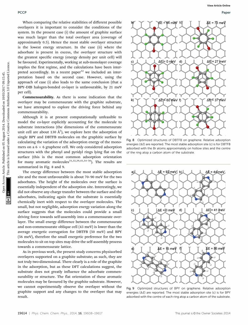
Commensurability. As there is some indication that theoverlayer may be commensurate with the graphite substrate,we have attempted to explore the driving force behind anycommensurability.
Although it is at present computationally unfeasible tomodel the co-layer explicitly accounting for the molecule tosubstrate interactions (the dimensions of the commensurateunit cell are about 130 Å2), we explore here the adsorption ofsingle BPY and DBTFB molecules on the graphitic surface bycalculating the variation of the adsorption energy of the mono-mers on a 6 � 6 graphene cell. We only considered adsorptionstructures with the phenyl and pyridyl rings lying flat on thesurface (this is the most common adsorption orientationfor many aromatic molecules31,32,39,41,54–56). The results aresummarized in Fig. 8 and 9.
The energy difference between the most stable adsorptionsite and the most unfavourable is about 70–90 meV for the twoadsorbates. The height of the molecules over the surface isessentially independent of the adsorption site. Interestingly, wedid not observe any charge transfer between the surface and theadsorbates, indicating again that the substrate is essentiallychemically inert with respect to the overlayer molecules. Thesmall, but not negligible, adsorption energy variation along thesurface suggests that the molecules could provide a smalldriving force towards self-assembly into a commensurate over-layer. The small energy difference between the commensurateand non-commensurate oblique cell (43 meV) is lower than theaverage energetic corrugation for DBTFB (50 meV) and BPY(56 meV), therefore the small energetic preference for the twomolecules to sit on top sites may drive the self-assembly processtowards a commensurate lattice.
As in previous work, the present study concerns physisorbedoverlayers supported on a graphite substrate; as such, they arenot truly two-dimensional. There clearly is a role of the graphitein the adsorption, but as these DFT calculations suggest, thesubstrate does not greatly influence the adsorbate commen-surability or structure. The flat orientation of these aromaticmolecules may be favoured by the graphite substrate. However,we cannot experimentally observe the overlayer without thegraphite support and any changes to the overlayer that mayresult.
Fig. 8 Optimized structures of DBTFB on graphene. Relative adsorptionenergies (DE) are reported. The most stable adsorption site (c) is for DBTFBadsorbed with the Br atoms approximately on hollow sites and the centreof the ring atop a carbon atom of the substrate.
Fig. 9 Optimized structures of BPY on graphene. Relative adsorptionenergies (DE) are reported. The most stable adsorption site (c) is for BPYadsorbed with the centre of each ring atop a carbon atom of the substrate.
PCCP Paper
Ope
n A
cces
s A
rtic
le. P
ublis
hed
on 0
5 A
ugus
t 201
4. D
ownl
oade
d on
10/
03/2
017
09:1
5:45
. T
his
artic
le is
lice
nsed
und
er a
Cre
ativ
e C
omm
ons
Attr
ibut
ion
3.0
Unp
orte
d L
icen
ce.
View Article Online

This journal is© the Owner Societies 2014 Phys. Chem. Chem. Phys., 2014, 16, 19608--19617 | 19615
Discussion
We have identified the formation of a halogen bonded co-crystalof BPY and DBTFB. Significantly the overlayer structure has beendetermined and the C–Br� � �N halogen bond angle between thebromine and the nitrogen (as determined from the overlayerX-ray diffraction structure) is found to be approximately 1581 andnot linear. The DFT results are in reasonable agreement (4.5%error) with this conclusion, also indicating a bent bond angle of163.41 after geometry optimisation.
Interestingly this combination of species is also found toform non-linear halogen bonds in the bulk, although thehalogen bond in the monolayer is somewhat less linear(�8%) than in the bulk structure (176.401/177.711), althoughvery similar to some of the halogen bond angles observed forrelated perfluoroaryl bromide species (B1631).35 This halogenbond angle is also much less linear than that observed foranalogous halogen bonded co-layer of BPY–DITFB, which wasessentially linear with a bond angle of B1801.
The presence of an electropositive region, the s-hole,57
(visible as a blue cloud atop the Br atom in the electron densitydifference plot in Fig. 6) confirms this topological feature as asignature for halogen bonding interactions. Both the non-linear molecular geometry and the relatively long (on average,3.07 Å from DFT and 3.19 Å experimentally – 8% shorter thanthe sum of the vdW radii) internuclear separation (DFT calcula-tions suggest 15% longer than in the BPY–DITFB monolayer32)between the bromine and the nitrogen atoms point to thepresence of a halogen bond weaker than for the BPY–DITFBcase. This is confirmed by the DFT results, which indicate thateach halogen bond imparts a stabilisation of 136 meV, about a
46% smaller energy contribution than for the N� � �I halogenbond in the BPY–DITFB co-layer.
The lateral interchain H-bonding interactions in the BPY–DBTFB monolayer are somewhat different from the BPY–DITFBmonolayer. In the BPY–DBTFB co-layer there is a bifurcatedH-bond between one of the DBTFB fluorines and two of the BPYhydrogens with an average length of 2.595 Å after DFT geometryoptimisation, and an energy of 60 meV each, making the totalbinding energy contribution from the lateral interactionsalmost equivalent (12% smaller) to that provided by the weakN� � �Br halogen bonds. In the BPY–DITFB co-layer there arelateral hydrogen bonds of about the same average length(B2.52 Å) but with a total energy (248 meV), approximatelyhalf of the bonding energy coming from two strong N� � �Ihalogen bond (498 meV). This suggests that the non-linearorientation of BPY and DBTFB molecules arises from moreimportant lateral interactions (the F–H hydrogen bonds)with weaker N� � �Br halogen bonding, than in the BPY–DITFBco-layer. This is confirmed by a comparison with calculationsfor the hypothetical linear BPY–DBTFB structure, which showthat the small increase in halogen bond strength resulting fromlinear bonds is more than offset by the decrease in interchainH-bonding, resulting in a less stable structure overall. Theseresults are consistent with the general trend that correlateshalogen bonding strength with atomic polarisability (increasingfrom bromine to bromine due to the increasing dimension ofthe halogen atoms). We also note that experimentally andtheoretically there is some tentative evidence to suggest thatthe co-layer could be commensurate, which was not observed forthe BPY–DITFB co-layer.
Table 2 The calculated halogen bond strength of complexes of BPY with halobenzenes when physisorbed on a graphite surface at B0.5 monolayercoverage
Interaction
Halogen bondstrength perbond/meV
DFT Diffraction
Bond angle(degrees)
Bondlength/Å
Bond angle(degrees)
Bondlength/Å
% of sumof vdW radii
BPY–DITFB 249 178 2.67 180 2.84 80
BPY–DBTFB 136 163 3.07 158 3.19 92
BPY–DIBa 125 179 2.86 — — —
a This co-layer has not been observed experimentally, and the strength of the halogen bond has been calculated to be too weak to drive theformation of a mixed layer. Instead, values have been calculated using DFT for a hypothetical (metastable) structure isomorphic with theBPY–DITFB co-layer.
Paper PCCP
Ope
n A
cces
s A
rtic
le. P
ublis
hed
on 0
5 A
ugus
t 201
4. D
ownl
oade
d on
10/
03/2
017
09:1
5:45
. T
his
artic
le is
lice
nsed
und
er a
Cre
ativ
e C
omm
ons
Attr
ibut
ion
3.0
Unp
orte
d L
icen
ce.
View Article Online

19616 | Phys. Chem. Chem. Phys., 2014, 16, 19608--19617 This journal is© the Owner Societies 2014
In an attempt to understand which halogen bonds have thedirectionality and robustness to overcome other intermolecularinteractions and be used reliably for controlling molecularself-assembly in physisorbed layers, we can combine theseresults with previous studies to begin to construct a hierarchyof different halogen bonds in physisorbed monolayers. Theresults so far for BPY-based halogen bonds are listed in Table 2and indeed follow the trends outlined above.
Acknowledgements
We acknowledge financial support for AB from EPSRC DTA awardfrom the Department of Chemistry, University of Cambridge. Weacknowledge Diamond Light Source for time on beamline I11under proposals EE6511 and EE7761.
References
1 J. A. A. W. Elemans and S. De Feyter, Structure and functionrevealed with submolecular resolution at the liquid-solidinterface, Soft Matter, 2009, 5, 721–735.
2 S. De Feyter and F. C. De Schryver, Two-dimensional supra-molecular self-assembly probed by scanning tunnelingmicroscopy, Chem. Soc. Rev., 2003, 32, 139–150.
3 T. Kudernac, S. Lei, J. A. A. W. Elemans and S. De Feyter,Two-dimensional supramolecular self-assembly: nanoporousnetworks on surfaces, Chem. Soc. Rev., 2009, 38, 402–421.
4 D. Braga, F. Grepioni, L. Maini and M. Polito, MolecularNetworks, Springer, Berlin, 2009.
5 K. Morishige and T. Kato, Chain-length dependence ofmelting of n-alcohol monolayers adsorbed on graphite:n-hexanol, n-heptanol, n-octanol and n-nonanol, J. Chem.Phys., 1999, 111, 7095–7102.
6 K. Morishige and Y. Sakamoto, Melting of n-butanol andn-pentanol monolayers adsorbed on graphite: effects ofmolecular length on melting, J. Chem. Phys., 1995, 103,2354–2360.
7 L. Messe, S. M. Clarke, A. Inaba, T. Arnold, C. C. Dong andR. K. Thomas, The Mixing Behaviour at the Solid/LiquidInterface: Binary Monolayers of Linear Alcohol Adsorbed onGraphite, Langmuir, 2002, 18, 4010–4013.
8 L. Messe, S. M. Clarke, A. Inaba, C. C. Dong, R. K. Thomas,M. A. Castro and M. Alba, Mixing Behaviour at the Solid/Liquid Interface: Binary Alcohol Monolayers on Graphite,Langmuir, 2002, 18, 9429–9433.
9 K. Morishige, Y. Takami and Y. Yokota, Structures ofalkanes and alkanols adsorbed on graphite in solution:comparison with scanning tunneling microscopy images,Phys. Rev. B: Condens. Matter Mater. Phys., 1993, 48,8277–8281.
10 C. L. Claypool, F. Faglioni, W. A. Goddard III, H. B. Gray,N. S. Lewis and R. A. Marcus, Source of image contrastin STM images of functionalized alkanes on graphite: asystematic functional group approach, J. Phys. Chem. B,1997, 101, 5978–5995.
11 D. M. Cyr, B. Venkataraman, G. W. Flynn, A. Black andG. M. Whitesides, Functional Group Identification in Scan-ning Tunneling Microscopy of Molecular Adsorbates,J. Phys. Chem., 1996, 100, 13747–13759.
12 A. K. Bickerstaffe, N. P. Cheah, S. M. Clarke, J. E. Parker,A. Perdigon, L. Messe and A. Inaba, The Crystalline Struc-tures of Carboxylic Acid Monolayers Adsorbed on Graphite,J. Phys. Chem. B, 2006, 110, 5570–5575.
13 M. Hibino, A. Sumi and I. Hatta, Molecular arrangements offatty acids and cholesterol at liquid graphite interfaceobserved by STM, Jpn. J. Appl. Phys., 1995, 34, 3354–3359.
14 M. Hibino, A. Sumi, H. Tsuchiya and I. Hatta, Microscopicorigin of the odd even effect in monolayer of fatty acidsformed on a gaphite surface by STM, J. Phys. Chem. B, 1998,102, 4544–4547.
15 E. Kishi, H. Matusda, R. Kuroda, K. Takimoto, A. Yamano,K. Eguchi, K. Hatanaka and T. Nakagiri, Barrier-heightimaging of fatty acid Langmuir-Blodgett films, Ultramicro-scopy, 1992, 42–44, 1067–1072.
16 R. Kuroda, E. Kishi, A. Yamano, K. Hatanaka, H. Matsuda,K. Eguchi and T. Nakagiri, Scanning tunneling microscopeimages of fatty acid Langmuir-Blodgett bilayers, J. Vac. Sci.Technol., B, 1991, 9, 1180–1183.
17 T. Arnold and S. M. Clarke, Thermodynamic Investigation ofthe Adsorption of Amides on Graphite from Their Liquidsand Binary Mixtures, Langmuir, 2008, 24, 3325–3335.
18 K. S. Mali, B. Van Averbeke, T. Bhinde, A. Y. Brewer,T. Arnold, R. Lazzaroni, S. M. Clarke and S. De Feyter, ToMix or Not To Mix: 2D Crystallization and Mixing Behaviorof Saturated and Unsaturated Aliphatic Primary Amides,ACS Nano, 2011, 5, 9122–9137.
19 T. Bhinde, A. Y. Brewer, S. M. Clarke, T. K. Phillips,T. Arnold and J. E. Parker, Adsorption of UnsaturatedAmides on a Graphite Surface: trans-Unsaturated Amides,J. Phys. Chem. C, 2011, 115, 6682–6689.
20 T. Bhinde, S. M. Clarke, T. K. Phillips, T. Arnold and J. E. Parker,Crystalline Structures of Alkylamide Monolayers Adsorbed onthe Surface of Graphite, Langmuir, 2010, 26, 8201–8206.
21 R. E. Bucknall, S. M. Clarke, R. A. Shapton andR. K. Thomas, The structure of a methyl iodide monolayeradsorbed on graphite, Mol. Phys., 1989, 67, 439–446.
22 S. M. Clarke and R. K. Thomas, The structure of a bromo-methane monolayer adsorbed on graphite, Mol. Phys., 1991, 72,413–423.
23 K. Morishige, Y. Tajima, S. Kittaka, S. M. Clarke andR. K. Thomas, The structure of chloromethane monolayersadsorbed on graphite, Mol. Phys., 1991, 72, 395–411.
24 A. Inaba, H. Chihara, S. M. Clarke and R. K. Thomas, Thestructure and heat capacity of fluoromethane monolayersadsorbed on graphite, Mol. Phys., 1991, 72, 109–120.
25 R. Gutzler, O. Ivasenko, C. Fu, J. L. Brusso, F. Rosei andD. F. Perepichka, Halogen bonds as stabilizing interactionsin a chiral self-assembled molecular monolayer, Chem.Commun., 2011, 47, 9453–9455.
26 X. Yang, F. Wang, Q. Chen, L. Wang and Z. Wang, Halogenbonded two-dimensional supramolecular assemblies studied
PCCP Paper
Ope
n A
cces
s A
rtic
le. P
ublis
hed
on 0
5 A
ugus
t 201
4. D
ownl
oade
d on
10/
03/2
017
09:1
5:45
. T
his
artic
le is
lice
nsed
und
er a
Cre
ativ
e C
omm
ons
Attr
ibut
ion
3.0
Unp
orte
d L
icen
ce.
View Article Online

This journal is© the Owner Societies 2014 Phys. Chem. Chem. Phys., 2014, 16, 19608--19617 | 19617
by high resolution scanning tunneling microscopy, Chin. Sci.Bull., 2007, 52, 1856–1859.
27 Q. Chen, T. Chen, X. Zhang, L.-J. Wan, H.-B. Liu, Y.-L. Li andP. Stang, Two-dimensional OPV4 self-assembly and itscoadsorption with alkyl bromide: from helix to lamellar,Chem. Commun., 2009, 3765–3767.
28 A. C. Legon, The halogen bond: an interim perspective,Phys. Chem. Chem. Phys., 2010, 12, 7736–7747.
29 P. Metrangolo, H. Neukirch, T. Pilati and G. Resnati, Halo-gen Bonding Based Recognition Processes: A World Parallelto Hydrogen Bonding, Acc. Chem. Res., 2005, 38, 386–395.
30 E. Corradi, S. V. Meille, M. T. Messina, P. Metrangolo andG. Resnati, Halogen Bonding versus Hydrogen Bondingin Driving Self-Assembly Processes, Angew. Chem., Int. Ed.,2000, 39, 1782–1786.
31 S. M. Clarke, T. Friscic, W. Jones, A. Mandal, C. Sun andJ. E. Parker, Observation of a two-dimensional halogen-bonded cocrystal at sub-monolayer coverage using synchro-tron X-ray diffraction, Chem. Commun., 2011, 47, 2526–2528.
32 M. Sacchi, A. Y. Brewer, S. J. Jenkins, J. E. Parker, T. Friscicand S. M. Clarke, Combined Diffraction and Density Func-tional Theory Calculations of Halogen-Bonded CocrystalMonolayers, Langmuir, 2013, 29, 14903–14911.
33 R. B. Walsh, C. W. Padgett, P. Metrangolo, G. Resnati,T. W. Hanks and W. T. Pennington, Crystal Engineering throughHalogen Bonding: Complexes of Nitrogen Heterocycles withOrganic Iodides, Cryst. Growth Des., 2001, 1, 165–175.
34 S. Tsuzuki, A. Wakisaka, T. Ono and T. Sonoda, Magnitudeand Origin of the Attraction and Directionality of the Halo-gen Bonds of the Complexes of C6F5X and C6H5X (X = I, Br,Cl and F) with Pyridine, Chem. – Eur. J., 2012, 18, 951–960.
35 A. De Santis, A. Forni, R. Liantonio, P. Metrangolo, T. Pilati andG. Resnati, N� � �Br Halogen Bonding: One-Dimensional InfiniteChains through the Self-Assembly of Dibromotetrafluoroben-zenes with Dipyridyl Derivatives, Chem. – Eur. J., 2003, 9,3974–3983.
36 S. P. Thompson, J. E. Parker, J. Potter, T. P. Hill, A. Birt,T. M. Cobb, F. Yuan and C. C. Tang, Beamline I11 atdiamond: a new instrument for high resolution powderdiffraction, Rev. Sci. Instrum., 2009, 80, 075107.
37 S. P. Thompson, J. E. Parker, J. Marchal, J. Potter, A. Birt,F. Yuan, R. D. Fearn, A. R. Lennie, S. R. Street andC. C. Tang, Fast X-ray powder diffraction on I11 at diamond,J. Synchrotron Radiat., 2011, 18, 637–648.
38 H. P. Schildberg and H. J. Lauter, Lineshape calculations fortwo-dimensional powder samples, Surf. Sci., 1989, 208, 507–532.
39 A. Y. Brewer, T. Friscic, G. M. Day, L. M. Overvoorde,J. E. Parker, C. N. Richardson and S. M. Clarke, Themonolayer structure of 1,2-bis(4-pyridyl)ethylene physi-sorbed on a graphite surface, Mol. Phys., 2012, 111, 73–79.
40 S. J. Clark, M. D. Segall, C. J. Pickard, P. J. Hasnip,M. J. Probert, K. Refson and M. C. Payne, First principlesmethods using CASTEP, Z. Kristallogr., 2005, 220, 567–570.
41 A. Y. Brewer, M. Sacchi, J. E. Parker, C. L. Truscott,S. J. Jenkins and S. M. Clarke, The crystalline structure of
the phenazine overlayer physisorbed on a graphite surface,Mol. Phys., 2013, 111, 3823–3830.
42 H. J. Monkhorst and J. D. Pack, Special points for Brillouin-zone integrations, Phys. Rev. B: Solid State, 1976, 13, 5188–5192.
43 T. P. Hardcastle, C. R. Seabourne, R. Zan, R. M. D. Brydson,U. Bangert, Q. M. Ramasse, K. S. Novoselov and A. J. Scott,Mobile metal adatoms on single layer, bilayer, and trilayergraphene: an ab initio DFT study with van der Waalscorrections correlated with electron microscopy data, Phys.Rev. B: Condens. Matter Mater. Phys., 2013, 87, 195430.
44 J. P. Perdew, K. Burke and M. Ernzerhof, GeneralizedGradient Approximation Made Simple, Phys. Rev. Lett.,1996, 77, 3865–3868.
45 D. Vanderbilt, Soft self-consistent pseudopotentials in ageneralized eigenvalue formalism, Phys. Rev. B: Condens.Matter Mater. Phys., 1990, 41, 7892–7895.
46 E. R. McNellis, J. Meyer and K. Reuter, Azobenzene atcoinage metal surfaces: role of dispersive van der Waalsinteractions, Phys. Rev. B: Condens. Matter Mater. Phys.,2009, 80, 205414.
47 A. Tkatchenko and M. Scheffler, Accurate Molecular Van DerWaals Interactions from Ground-State Electron Density andFree-Atom Reference Data, Phys. Rev. Lett., 2009, 102, 073005.
48 A. Guinier and G. Fournet, Small-angle scattering of X-rays,Wiley, New York, 1955.
49 T. K. Phillips, S. M. Clarke, T. Bhinde, M. A. Castro,C. Millan and S. Medina, Monolayer structures of alkylaldehydes: odd-membered homologues, Thin Solid Films,2011, 519, 3123–3127.
50 S. M. Clarke, L. Messe, J. Adams, A. Inaba, T. Arnold andR. K. Thomas, A quantitative parameter for predictingmixing behaviour in adsorbed layers: the 2D isomorphismcoefficient, Chem. Phys. Lett., 2003, 373, 480–485.
51 J. E. Parker and S. M. Clarke, Mixing in Adsorbed Monolayers:Perfluorinated Alkanes, Langmuir, 2008, 24, 4833–4844.
52 A. K. Bickerstaffe and S. M. Clarke, The interpretation ofmixing behaviour in carboxylic acid monolayers adsorbedon graphite using a regular solution description, ColloidsSurf., A, 2007, 298, 80–82.
53 T. Arnold, J. E. Parker and P. Macdonald, Investigation ofthe Adsorption of Alkanes on Hexagonal Boron Nitride fromTheir Liquids and Binary Mixtures, J. Phys. Chem. C, 2012,116, 10599–10606.
54 S. M. Clarke, T. Friscic, A. Mandal, C. Sun and J. E. Parker,Monolayer structures of 4,40 bipyridine on graphite at sub-monolayer coverage, Mol. Phys., 2011, 109, 477–481.
55 P. Meehan, T. Rayment, R. K. Thomas, G. Bomchil andJ. W. White, Neutron diffraction from benzene adsorbed ongraphite, J. Chem. Soc., Faraday Trans. 1, 1980, 76, 2011–2016.
56 I. Gameson and T. Payment, Confirmation of the O7 � O7commensurate structure of a benzene monolayer adsorbedon graphite, Chem. Phys. Lett., 1986, 123, 150–153.
57 P. Politzer, P. Lane, M. Concha, Y. Ma and J. Murray, Anoverview of halogen bonding, J. Mol. Model., 2007, 13,305–311.
Paper PCCP
Ope
n A
cces
s A
rtic
le. P
ublis
hed
on 0
5 A
ugus
t 201
4. D
ownl
oade
d on
10/
03/2
017
09:1
5:45
. T
his
artic
le is
lice
nsed
und
er a
Cre
ativ
e C
omm
ons
Attr
ibut
ion
3.0
Unp
orte
d L
icen
ce.
View Article Online