supplementary text library/20041201.pdf · electricity generating authority of thailand ......
TRANSCRIPT

DEPARTMENT OF NUCLEAR TECHNOL~GY, FACULTY OF ENGINEERINGCHULALONGKORN UNIVERSITY
PHAYATHAI ROAD, BANGKOK 10330, THAILANDTEL: (662) 218-6772, (662) 218-6784. FAX: (662) 218-6770
E-mail: [email protected]
THAI - CANADIAN
NUCLEAR HUMAN RESOURCES DEVELOPMENT
LINKAGE PROJECT
TRAINING PROGRAM
NUCLEAR PHYSICS & REACTOR THEORY
SUPPLEMENTARY TEXT
Prepared by
John L. Groh
SPONSORED BY
ATOMIC ENERGY OF CANADA LIMITED
CANADIAN INTERNATIONAL DEVELOPMENT AGENCY
ELECTRICITY GENERATING AUTHORITY OF THAILAND
OFFICE OF ATOMIC ENERGY FOR PEACE

SUPPLEMENT TO CHAPTER 8OF
REACTOR PHYSICS FUNDAMENTALS
This supplement provides mathematical background and detailnot in the text. It also reviews the text material from severaldifferent points of view. You should be familiar with the textmaterial before studying this supplement.
Reactor Kinetics:Power Increase for a Step Ak In<:rease
with the Reactor Critical
Very Small Ak
SmallAk
LargeAk
How to Avoid Prompt Criticality
Power Rundown

Power Increase Mter a Step AI< Increase
Chapter 8 describes the reactor response when k is suddenly made greaterthan one. It ignores control system response and reactivity effects caused bychange in temperature or by changes in xenon-135 concentration.
The reactor response to a small L\k increment (e.g. for normal reactor control)is simple. The simple formula describing this is reviewed in section 1. below.For larger reactivity changes a more complicated formula is needed. Seesection 2. below. Even t..~is formula is no good for very large steps with.l1kclose to 11 Reactor behaviour in this ca~e is reviewed in section 3. below.
1. The simple formula P(t) oc et/' (8.3 on pages 6) can he derived without adifferential equation. U the initial thermal neutron population in thecritical reactor is No, then one generation after the reactivity addition thepopulation is:
After two generations it isAfter three generations it is
Nt =(1+Ak)NoN2 =(1+L\k)Nt =(1+.1k)2 NoN3 =(1+.1kpNo
and after n generations it is Nn= (1+L\k)n NoEquivalently, since neutron power is proportional to the neutron flux
Pn::': (1+L\k)npo
This is a perfectly good formula, but to make it look like the formula in thetext, use the properties of the natural log to write (1+L\k)n =enm(1..-&k)
When Ak « 1, In(l+Ak) ... AI<, so the equation can be written as Pn =Poen"kFinally, the average time for a generation is.L, so time t = n x.L and
P(t) =Poef'I</L>t
This looks exactly like equation 8.3 if the reactor period is 't =.L/Ak
2 Supplement to Chapter 8 of Reactor Theory Fundamentals

In this approximation the neutrons are considered as a single group. Theiraverage lifetime L, (calculated on page 10 as 0.993 x 0 + 0.007 ,: 13"" 0.091 s)can be written using algebra:
L"" (1-13) X{+ p/A"" p/A
1: =L/Ill< "" 13/(Mk)withP(t) "" Po et/'
If we use this fommla, equation 8.3 becomes.
*The single group approximation is excellent for small Ak values, notmore than a tenth of a mk, typical of the reactivity used for normalreactor power mailoeuvTing.
A feature of an exponential power rise is ~at the rate of change of the logpower is constant. Chapter 10 discusses the following useful equation.
tInP(t)=lnp.+- so
f
dlnP(t) (J... dP)=.!.dt Pdt f
The reactor responds to a small reactivity step at low power with a constantfractional increase each second. The physical meaning of the reactor period,1:, is that its inverse measures this constant fractional rate of increase.
Pages 9 & 10 demonstrate a very fast power increases IF all the neutrons areprompt. No such reactor exists, but the reactor behaviour described is muchlike a prompt critical reactor (Ak =~), discussed in section 3. below.Operation inwhich Ak approaches ~ cannot be allowed.
For reference, here are text values of the constants.Diffusion Time (.., 0.001 sAverage Lifetime L'" ~/).= 0.1 sDelaved Neutron Decay Constant). .... 0.08 S-l (1/).'" 125 s)Delayed Neutron Fraction ~ = 0.007 (fresh fuel),
13 .., 0.056 (equilibrium fuelling)L changes a little with fuel burnup because of the variation in ~.
Supplement to Chapter 8 of Reactor Theory Fundamentals 3

Figure 1. Power Rise following a +0.5 mk step increase in reactivity(AI< = 0.0005) in a critical core with J3 = 0.00582, e= 0.88 InS, A. = 0.0758 S·l.
Power Rise
1.10 ,
1.08 ~
~ 1.06.
L 1.04 ,
1.02 ,
4
1.00 :.•.••_-~.•_+..•~...••.• ---oi-.•_-~ --'-.._ _ ..~••o ~ M ~ M M 1
TIm. (s.conds'
Supplement to Chapter 8 of Reactor Theory Fundamentals
2. For analysis of upsets, where larger Ak step increases of 2 or 3 mkcouid occur, the one group formula is not accurate. A better methodkeeps track of two separate groups of neutrons: prompt and delayed.The delayed neutrons are lumped together in one group with a lifetime '"12.5 s, and a decay constant, A= (1/12.5) S·l = 0.08 S·l.
THE SIMPLIFIED TWO NEUTRON GROUP FORMULA
P(t) = Po UV«(3-Ak)] et/' [formula 8.6 on page 16]'t = [(J3-Ak)/{A. Ak)] .[formula 8.5 on page 15]
To get the new formula for P and 1: from the old ones, substitute:Po~ Po x [(3/(~-Ak)] hlto P(t) = Po et/' and). ~ Ax £(3/«(3-&)] into .'t = 13/(A.6.k)
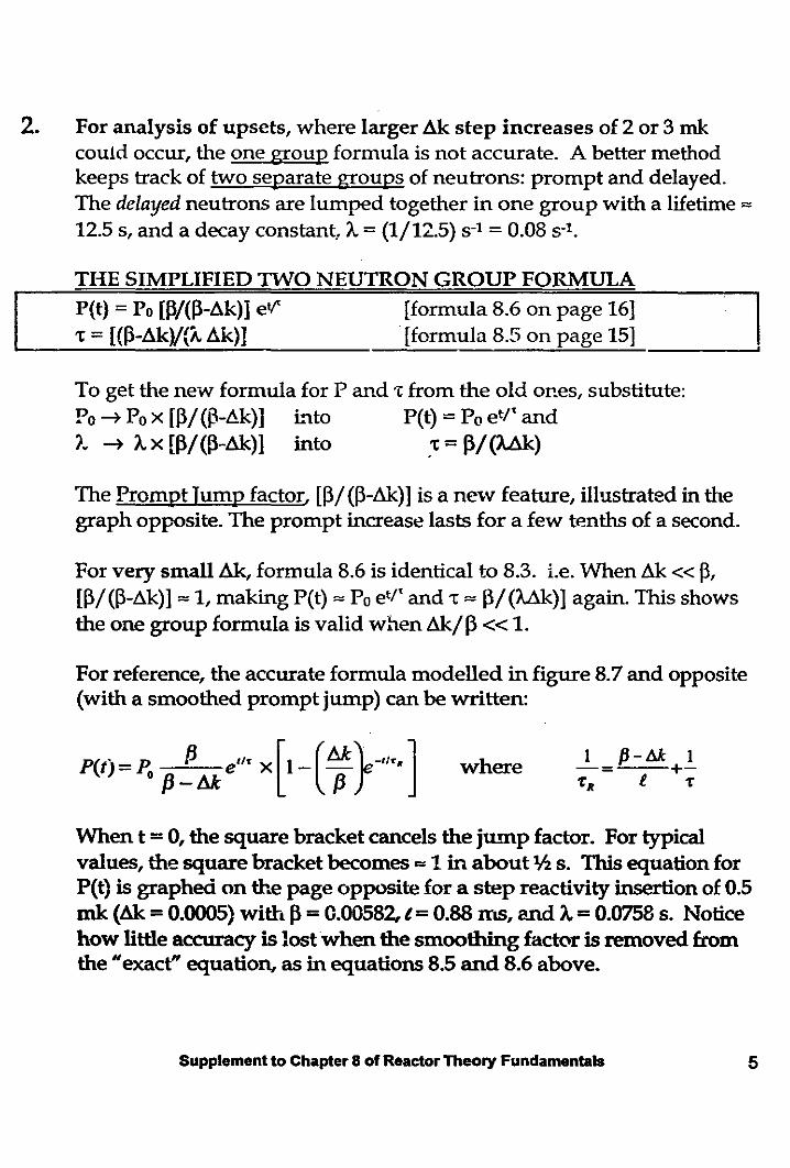
The Prompt Jump factor, [(3/ «(3-&)] is a new feature, illustrated in thegraph opposite. The prompt increase lasts for a few tenths of a second.
For very small Ak, formula 8.6 is identical to 8.3. I.e. When Ak « 13,[(3/ «(3-.6.k)] '" 1, making P(t) '" Po et/' and 't = Il/(Uk)] again. This showsthe one group formula is valid when &/13« 1.
For reference, the accurate formula modelled in figure 8.7 and opposite(with a smoothed prompt jump) can be written:
P(t) =Po f3!.6.k e"' x [1-(~}-'I'. ] where 1 P-lik 1-= +-TR I. T
When t =0, the square bracket cancels the jump factor. For typicalvalues, the square bracket becomes ... 1 in about th s. This equation forP(t) is graphed on the page opposite for a step reacthity insertion of 0.5mk (Ak =0.0005) with 13 =0.00582, t =0.88 ms, and A. =0.0758 s. Noticehow little accuracy is lostwhen the smoothing factor is removed fromthe "exact" equation, as in equations 8.5 and 8.6 above.
Supplement to Chapter 8 of Reactor Theory Fundamentals 5

To better understand where this formula comes from, we will now expand onthe discussion in section 8.5 of the text.
• Figure 2., represents the initial steady state. Make sure you can reproducethe numbers. Parameters have been changed, as in the text. An unrealisticvalue for /3, the delayed neutron fraction (10% instead of 1h%), make iteasier to see the effect of the precursor ba..'1l<.
The precursor bankconcentration, C, isinferred from the decaysper second, ')."C ,multiplied by the timefor one cycle, t, to give100 decays per cycle.
Initially, k =1, N = 1000,with decay constantA. = 0,1 S·l, (i.e. delayedneutron lifetime of 10 s),prompt neutron lifetime,t = 0.001 s and, forillustration /3 =0.100,
j3)kN j3kNFISSION kN900 100
1 x 1000.&-
I • :! .. ,Jut(
t ')..C ::; 100 BANKPT C =1,000,000
:S ~ DELAYED
(1-
N1000
PROMe= 1 m
C 1000 :"'"" 10 s delay____ -/ ",=0.1 S·1
TN for Beginning of Next Cycle
Figure 2. Neutron Balancefor a Critical Reactor
• In figure 3 notic~ the rise in prompt neutron population in the first 3 cyclesafter adding reactivity. The increase is slightly less in successivegenerations. This is because no extra neutrons have arrived from theprecursor bank (delay tank).
Precursors accumulate, but to increase the delayed neutron contributionfrom 100 to 101, the precursor tank must increase by 10,000 neutrons.
6 Supplement to Chapter 8 of Reactor Theory Fundamentals

Continuing withthis arithmetic for50 cycles brings usto figure 5.
At the same time,the accumulation inthe precursor bankstarts out small, butincreases from onegeneration to thenext.
Initially there is arapid (butdecreasL'1g)increase in theprompt neutronpopulation.
These figuresreproduce exactlythe values in figure8.4 of the text.
the thIrd cycleC 1128
1000 For illustrationk = 1.050ak= 50mk
1.051Jx1000 13 = 0.10090% = 945 :::1050 10% = 105
!PRECURSOR
100 BANKADDS
~1045 Increase of 45 in
the first cycle
9581.050 x 1045
110=1098
1PRECURSOR
100 BANKADD 10
lIncrease of 43 in
C 108 the second cycle
102€1.050 x 1088
114=1142
1PRECURSOR
100 BANKADD 14
~ Increase of 40 in-- .
Figure 4. The First Three Cycles after a Step Reactivity AdditionSupplement to Chapter 8 of Reactor Theory Fundamentals 7

1767
16701.050 x 1767
186= 1856
1PRECURSOR
100 BANK
r ,ADD 86
INCREASE OF 3
1770 FROM CYCLE 49
1770 START GENERATION 51
After 50 cycles theprompt populationincreases by only 3 fromone cycle to the next,but precursors areaccumulating at about86 each cycle.
The prompt rise isapproaching its end, andthe precursor bank isincreasing by nearly thesame large amount eachcycle.
Figure 5. 50 cycles after the initial step f'eactivity increase
1818
17181.050 x 1818
191= 1909
1PRECURSOR
100 (+ 1) BANK NOW
r OVER 1,010,100
NO CHANGE
1818 FROM PREVIOUSCYCLE
1818 AGAIN START GENERATION 131
Finally, in figure 6., theprecursor bank is bigenough to produce anextra delayed neutron.
Just as the prompt riseruns out of steam, extraprecursors begin toarrive to continue therise, which nowincreases from cycle tocycle.
Figure 6. 130 Cycles After a Step Reactivity Increase
Notice that the short time duration of the prompt jump is governedessentially by the prompt neutron lifetime. It is all over in a few hundred8 Supplement to Chapter 8 of Reactor Theory Fundamentals

cycles, a fraction of a second. The continued rise after the prompt jump endsdepends on the rate of decay of the precursor bank, and is essentiallygoverned by the lifetimes of the delayed neutrons. Of course the size andduration of the prompt jump and the size of the stable reactor period, 1:, alsodepend on the reactivity inserted, dk, and on the delayed neutron fraction, Itbeth of which are artificially large in this numerical example.
3. Analysts use numerical methods to solve the power rise problemaccurately; keeping track of the individual yields and lifetimes of each groupof delayed neutrons. (See table 2.3 in Chapter. 2).
The method just used can be extended using a spreadsheet with separateprecursor banks, or other methods may be used. Simulations may keep trackseparately of as many as 33 groups of delayed neutrons, 6 each from fissionproducts from U-235, U-238 fast fissions, Pu-239 and Pu-241 together with 9groups of photo-neutrons.
The result is plotted, inaccurately, as Figure 8.8 in the text. An accurate plotallows t...J,.e stable reactor period to be found for any dk insertion. The graphduplicates the formula values of 1: for & «13. (!be formula, with smoothingterm, also works for values of & » J3!)
The graph can be used to find the period for larger values of &, includingvalues with & ... 13, the prompt critical reactor. The condition for promptcriticality is that the reactor be critical on prompt neutrons alone, ignoring theeffect of the delayed neutrons. From figure 2 this cond:tion is:
k(l-P)N = N ~ (1 + &.)(1- P) = 1~1- P + & - P& =1~ P = &/k
For CANDU reactors the period at prompt criticality is 't ... 1 s. There is nosudden change in reactor behaviour at prompt criticality. Effective control islost well before prompt criticality is reached. Figure 8.8 shows a trip shouldoccur if the period drops as low as 10 s.
Supplement to Chapter 8 of Reactor Theory Fundamentals 9

CANDU Features That Reduce The Chance Of Prompt Criticality
The features most often quoted in CANDU literature are:• reactivity devices with slow rates of reactivity addition and limited
positive reactivity worth.• two independent, diverse, fast acting shutdown systems (SDSs) act to limit
the power increase and to hold the reactor shut down if other devices failto limit reactivity addition.
Reactivity additions are inhibited by software, by hardwired logic & bymechanical design. If the regulating system or rod drive interlocks fail,the equipment limits the rate of reactivity addition.
• For example, the small tubing used in the LZC system limits reactivityaddition to about + 0.15 rrikj s even if the outlet tubing is sheared off.
• Small motors used for rod drives limit the maximum rate of rodwiihdrawal.
Design constraints are enforced by commissioning, testing, change control,maintenance, control of the operating envelope, defined impairmentlevels, prompt CRO actions on alarms or impairments, SDS aVailability.
Additional design features are less often quoted:• The CANDU positive void coefficient (its worst +Ak accident) is "small",
and the maximum rate of voiding allows sufficient time for the SDSs to act.Note that a large negative void coeffici~nt is also unsafe. The core could get intoan abnormal voided stateJollowedby void collapse caused, e.g. by actions taken tocool the fuel.
• The promptneutron lifetime,e... 1 m s, is longer than the lightwater reactorpromptneutron lifetime,e... 0.3 l1IS. This limits the rate of rise.[The longer lifetime results becauseD:2O moderates less quickly thanH2,O andbecause we over moderate, achieving a well therma!ized spectrum]
• Thereactivity insertion£or prompt aiticaIity is higher thanfor reactors with veryhigh fuel bumup, Le. withhigh plutoniumcontent[High plutoniumcontent decreases the Ak required to get a high rate of rise.]
10 Supplement to Chapter 8 of Reactor Theory Fundamentals

POWER RUNDOWN
The formulas for power increase (fission rate increase) also work when neutronabsorber is inserted. Operationally, CANDU reactivity devices, designed toinsert positive reactivity slowly, can insert large negative reactivity quickly,giving a large, fast prompt drop. This is discussed in more detail in Chapter 10.
*
*
Neutron Power Rundown: (see ChapterlO, figure 10.2).
A prompt drop, P/(P - 6k), with llk a negative number, is followed by a
more gradual power decrease, oc e-At, as the D.N. precursor bank decays.Since there are several groups of delayed neutrons, there is a sequence ofsuch de(:ays that drop out one at a time· as the precursors with shorter haHlives disappear. 1his is followed by the slow gradual rundown as thephoto-neutron sources decay.
Photo-neutrons, neutrons generated in heavy water by energetic gammarays, are amplified by the core configuration. 1his produces measurableflux. until the source fission products decay. Subcritical multiplication ofneutron sources is discussed in detail in Chapter 9.
Thermal Power Rundown: (See figure 10.1).
Notice that thermal power js not proportional to fission rate, especially atlow power. This is mainly because of the decay heat, which decreasesslowly. Pump heat and ambient losses contribute to non-linearity betweenthermal and neutron power.
At full power (or immediately after shutdown), the fission product decayheat is 6% to 7% of F.P. This decays to about 3% in 3 minutes, and tobelow 1% in 8 hours. 3% is a significant number. Many CANDU backupsystems (e.g. auxiliary boiler feedwater pump) are sized to handle decayheat after shutdown. Typically they are sized for about 3% full power.
Supplement to Chapter 8 of Reactor Theory Fundamentals 11

Differential Equations for the Time Response
The differential equations for the thermal neutron density, N(t), and thedelayed neutron precursor concentration, C(t), derived in many textbooks,are (for a single delayed neutron group):
R Lo (N) dln(N) _I dN = (p-j3) +.AC andate g = dt N dt 'e N
dC = /lIeN _ I,Cdt e
These equations are consistent with the numerical model, redrawn in figure 7using algebraic symbols.
tiN (N'-N)-=dt e(l-p).W N
=-----+ACe e
This is the equationabove with (k-l)/k = Pand setting the overallmultiplier k =1(smallAk)
rearranging(3)kN FISSION kN I3kN
.£.
PRECURSOR
O"C BANKCT
!s DELAYED
1N
C N' ~ 10 s delay_ __'_/ 1 =0.1 s"
---JN for Beginning of Next Cycle
(1-
PROMP(=1 m
Figure 7. A Typical Neutron Generation
Similarly, the acCumulation in the precursor bank during the cycle is
~kN - o..C so (dCIdt), accumulation per second, is given by ~~= p~ - 'A.C
12 Supplement to Chapter 8 of Reactor Theory Fundamentals

Looking at the two terms that contribute to the rate log in
dln(N) 1 dN (p-~) 'A.CROleLog(N) = ---= +-
dt N dt f. N
you may be able to cOilvince yourself that this equation models the dynamicbehaviour. Before the reactivity insertion p = 0 and the rate of change ofneutron density (left hand side of the equation) is also zero so we have aninitial precursor bank concentration Co = (3Nol (tA)
With a step increase in positive reactivity, p, the rate goes up quickly as thefirst term on the right hand side increases immediately. As N increases theACoiN term drops and the rate of increase slows as (ACo)I (NIt) approaches
(~-p). Notice that N ~ NO [!3/(I3-p)] is exactly the change in N required toreduce the rate of increase to zero if the delayed neutron concentration, C,stays at its initial value, Co. i.e the prompt jump NO [(31 (13-p)], increases thepopulation of neutrons, N, just enough to make the right hand side of theequation zero again (temporarily).
As C gradually increases from the initial value, Co, N and C increase togetherso there is a constant rate log, cOlTesponding to an exponential powerincrease. The value of N increases in lock step with C.
Notice that if, somehow, the delayed neutrons could be turned off, [set C = 0in the equation], with a reactivity of zero the power would be decreasingfrom one generation to the next. The reador is subcritical without thedelayed neutrons; it depends on the delayed neutrons to "top up" theneutrons in each neutron cycle to keep the reactor critical. On powermaneuvers, the dynamic response of the reactor is controlled, apart from theprompt jump, by the slow rate of change of the delayed neutron precursorconcentrations.
The initial prompt jump represents a step increase in fission rate over arelatively small number of neutron cycles. The prompt jump is halted whenthis higher fission rate cannot be "topped up" by the delayed neutrons whichhave not yet begun to increase.
Supplement to Chapter 8 of Reactor Theory Fundamentals 13

With a higher production rate of delayed neutron precursors, theconcentrations of the delayed neutrons gradually increase, each according toits hal! life. Subsequent increased decay from the "d~!ayedneutron bank" (or"reservoir") then drives the power up.
If the initial Gtep reactivity, p, increase is too big (equal to or greater than thedelayed neutron fraction, \3) it is impossible for the delayed neutron term,ACOiN, to decrease enough to bring the sum of two terms back to zero,halting the rise. The prompt jump continues without limit and the delayedneutrons do not get a chance to take control. The reactor is prompt critical,i.e. critical on prompt neutrons alone.
The reactor must be operated with p « 13 to keep the delayed neutrons incontrol
b summmy, the initial rate of rise (prompt jump) is governed by the promptneutron lifetime, independent of the delayed neutron lifetimes. Thesubsequent stable rate of rise depends on the rate of buildup of delayedneuiron precursors, which is governed by the delayed neutron precursordecay constants.
14 Supplement to Chapter 8 ofReactorTheory Fundamentals
15
Time Response in Three Dimensions.
ModellL'1.g the flux shape changes that occur during a reactor transient isoutside the scope of this course, but it may be useful to introduce some of thejargon here, to make it easier to read the advanced textbooks.
Time dependant reactor behaviour is often introduced in textbooks using thetime dependant diffusion equation. This is a differential equation thatmodels the time dependence of the thermal neutron flux distribution. Forhomogeneous reactors with simple geometric shapes the easiest solution is toseparate this equation into time and space equations. The space equation issolved for the flux shape, shown in Chapter 6, and solution of the timeequation produces the time dependence discussed in Chapter 8.
This is the point reactor model. The flux at each point in the reactor increases atexactly the same rate, leaVing tlle shape unchanged. This model works quitewell for fast transients, where shape changes are slower than the power rise.Accurate simulations of reactor behaviour use more sophisticated models.
For example, the separation into space and time dependant parts may bemodified to allow slow time dependant shape changes. This results in amodified point reactor model. Parameters in the time equation are averagedover the whole core and these averages change as the shape changes.
Other models solve the static flux shape diffusion equation for thefundamental flux shape and its hannonic modes. (The mathematical form ofthe equations for a cylindrical homogeneous reactor are the same as thesolutions for the vibrations of a cylindrical membrane!). The actual fluxshape is a superposition of the fundamental and its harmonics; and timedependence of the flux shape is determined from time dependant equationsfor the amplitudes of the shape components.
Supplement to Chapter 8 of Reactor Theory Fundamentals