superresolution with plenoptic camera 2 - tgeorgiev · superresolution with plenoptic camera 2.0 3...
TRANSCRIPT
Adobe Technical Report April 2009
Superresolution with Plenoptic Camera 2.0
Todor Georgiev and Andrew Lumsdaine
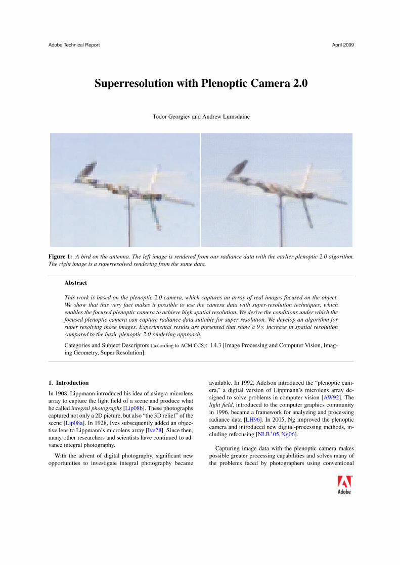
Figure 1: A bird on the antenna. The left image is rendered from our radiance data with the earlier plenoptic 2.0 algorithm.The right image is a superresolved rendering from the same data.
Abstract
This work is based on the plenoptic 2.0 camera, which captures an array of real images focused on the object.We show that this very fact makes it possible to use the camera data with super-resolution techniques, whichenables the focused plenoptic camera to achieve high spatial resolution. We derive the conditions under which thefocused plenoptic camera can capture radiance data suitable for super resolution. We develop an algorithm forsuper resolving those images. Experimental results are presented that show a 9× increase in spatial resolutioncompared to the basic plenoptic 2.0 rendering approach.
Categories and Subject Descriptors (according to ACM CCS): I.4.3 [Image Processing and Computer Vision, Imag-ing Geometry, Super Resolution]:
1. Introduction
In 1908, Lippmann introduced his idea of using a microlensarray to capture the light field of a scene and produce whathe called integral photographs [Lip08b]. These photographscaptured not only a 2D picture, but also “the 3D relief” of thescene [Lip08a]. In 1928, Ives subsequently added an objec-tive lens to Lippmann’s microlens array [Ive28]. Since then,many other researchers and scientists have continued to ad-vance integral photography.
With the advent of digital photography, significant newopportunities to investigate integral photography became
available. In 1992, Adelson introduced the “plenoptic cam-era,” a digital version of Lippmann’s microlens array de-signed to solve problems in computer vision [AW92]. Thelight field, introduced to the computer graphics communityin 1996, became a framework for analyzing and processingradiance data [LH96]. In 2005, Ng improved the plenopticcamera and introduced new digital-processing methods, in-cluding refocusing [NLB∗05, Ng06].
Capturing image data with the plenoptic camera makespossible greater processing capabilities and solves many ofthe problems faced by photographers using conventional
2 Todor Georgiev and Andrew Lumsdaine
digital cameras. Unfortunately, traditional plenoptic camerasrender images at very low resolution. For example, imagesrendered from Ng’s camera data have a final resolution of300×300 pixels. The early plenoptic cameras had such lowresolution because of the way they sampled the 4D radianceof the scene. This sampling was based on the assumption thatspatial and angular information was captured independently.The position of the microlenses captured spatial informationwhile the pixels under each microlens sampled the angulardistribution at the position of each microlens.
A different approach (called the plenoptic 2.0 camera, orthe focused plenoptic camera) can render final images atmuch higher resolution than the original plenoptic camera.A number of researchers have noted this camera as an in-teresting alternative to the plenoptic camera. Surprisingly, afigure describing the idea can be seen in the early 1908 workof Lippmann [Lip08b], but this camera has been indepen-dently considered by Ng [Ng06], Fife [FEW08], and Lums-daine [LG08]. The camera is structurally different from theearlier plenoptic 1.0 camera with respect to microlens place-ment, microlens focus, and, most importantly, with respectto assumptions made about sampling positional information.Lens placement in this new camera focuses the microlenseson the image inside the camera rather than at infinity. Thisstructural change introduces a flexible trade-off in the sam-pling of spatial and angular dimensions and allows multiplepixels from each microlens to be rendered into the final im-age.
In the existing approaches to plenoptic 2.0 rendering, thetrade-off between spatial and angular resolution is deter-mined by parameters in the camera optics. Depending ondepth, some portions of the scene may have more angularsamples (and correspondingly, a lower spatial resolution)than others. As we will see in the paper, these additionalsamples of the same spatial area of the scene can be usedto further increase the spatial resolution of that area throughthe use of super resolution.
Super resolution is a widely used technique for increasingthe resolution of images [NB03, BK02, BS98, EF97, Hun95,LS04, Sch02]. There are many different methods for em-ploying super resolution, but they all rely on extracting sub-pixel information from multiple images of a given scene toproduce one higher-resolution image. For lightfield capturebased on arrays of separate cameras, such as the Stanford ar-ray [WJV∗05], it seems clear that super resolution would bedirectly applicable.
As we will show in the paper, the plenoptic 2.0 cameraworks as an array of cameras. These cameras are focused onthe photographed object, a unique feature that distinguishesthe plenoptic 2.0 camera from the conventional plenoptic(1.0) camera. Based on this feature, we will develop andapply super-resolution techniques to the rendering of lightfields captured by the plenoptic 2.0 camera.
Concurrent with the initial submission of this paper to
EGSR 2009, the paper [BZF09] appeared in publication.The approach presented in [BZF09] applies superresolutionto the sub-sampled images obtained at each of the differentviews captured accross the microlens array. The authors de-velop a sophisticated image formation and restoration modeland apply a blind deconvolution restoration approach. Al-though there has been only a very brief window of time forus to study this related work, it appears to be of high qual-ity and great value. There are several key differences withour approach. Our work specifically interprets the plenop-tic camera in terms of the focused plenoptic camera. Thisresults in the use a different image formation model, one inwhich we account explicitly for sub-pixel registration. Basedon this model, we present a camera design that is guaranteedto produce sub-pixel offsets between microlens images forobjects at optical infinity. Those offsets are precisely com-puted from camera geometry and very reliable. Even if ourapproach is specifically targeted at super resolving for ob-jects at infinity, we provide an analysis of the opportunitiesfor superresolution at different depths in the scene and dis-cuss the interactions between magnification factor and su-perresolution. Finally, our approach uses an experimentallaymeasured kernel in conjunction with the sub-pixel registra-tion.
The plan of the paper is as follows: In Section 2, we willcompare and contrast the plenoptic 1.0 and plenoptic 2.0cameras, particularly in terms of trade-offs in spatial and an-gular resolution. In addition, we will show that the plenoptic2.0 camera is equivalent to an array of cameras, each onefocused on the object being imaged. Section 3 will describeour camera setting and our approach for applying super res-olution. Experimental results will be presented in Section 4and Section 5 will conclude.
Contributions:
1. We find the expressions for the positions and parametersat which super resolution is possible with the plenoptic2.0 camera.
2. We develop and analyze several classes of super-resolution algorithms for the plenoptic 2.0 camera.
3. We propose and demonstrate a practical method of superresolving objects at optical infinity with a plenoptic 2.0camera.
2. Plenoptic Cameras
2.1. The Plenoptic Camera 1.0
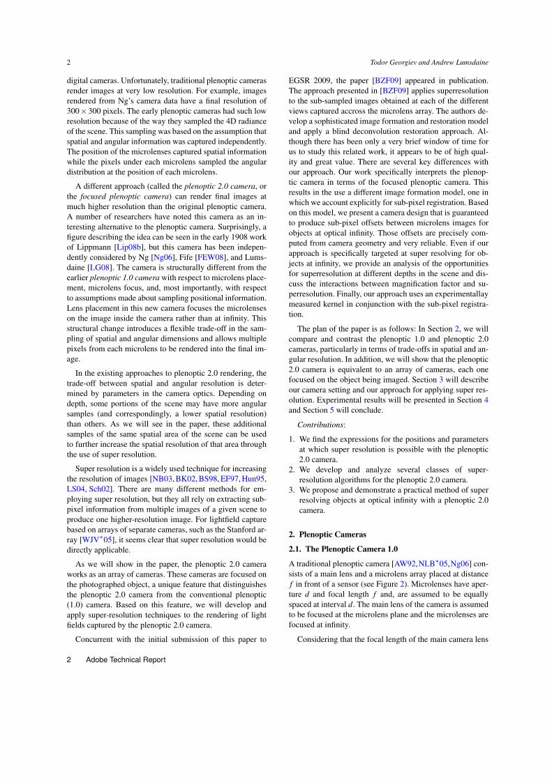
A traditional plenoptic camera [AW92,NLB∗05,Ng06] con-sists of a main lens and a microlens array placed at distancef in front of a sensor (see Figure 2). Microlenses have aper-ture d and focal length f and, are assumed to be equallyspaced at interval d. The main lens of the camera is assumedto be focused at the microlens plane and the microlenses arefocused at infinity.
Considering that the focal length of the main camera lens
2 Adobe Technical Report
Superresolution with Plenoptic Camera 2.0 3
f
d
Figure 2: Plenoptic 1.0 (traditional) camera. The main lensis focused at the microlens plane and the microlenses arefocused at optical infinity (equivalently, the main lens).
d
b a
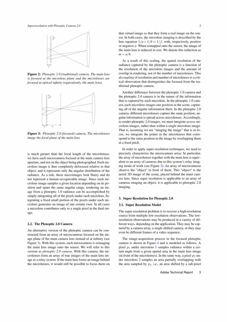
Figure 3: Plenoptic 2.0 (focused) camera. The microlensesimage the focal plane of the main lens.
is much greater than the focal length of the microlenses,we have each microcamera focused at the main camera lensaperture, and not on the object being photographed. Each mi-crolens image is thus completely defocused relative to thatobject, and it represents only the angular distribution of theradiance. As a rule, these microimages look blurry and donot represent a human-recognizable image. Since each mi-crolens image samples a given location depending on its po-sition and spans the same angular range, rendering an im-age from a plenoptic 1.0 radiance can be accomplished bysimply integrating all of the pixels under each microlens. In-tegrating a fixed small portion of the pixels under each mi-crolens generates an image of one certain view. In all casesa microlens contributes only to a single pixel in the final im-age.
2.2. The Plenoptic 2.0 Camera
An alternative version of the plenoptic camera can be con-structed from an array of microcameras focused on the im-age plane of the main camera lens instead of at infinity (seeFigure 3). With this system, each microcamera is reimagingthe main lens image onto the sensor. We will refer to thisversion as plenoptic 2.0 camera. With this camera, the mi-crolenses form an array of true images of the main lens im-age as a relay system. If the main lens forms an image behindthe microlenses, it would still be possible to focus them on
that virtual image so that they form a real image on the sen-sor. In both cases, the microlens imaging is described by thelens equation 1/a + 1/b = 1/ f , with, respectively, positiveor negative a. When remapped onto the sensor, the image ofthe main lens is reduced in size. We denote this reduction asm = a/b.
As a result of this scaling, the spatial resolution of theradiance captured by the plenoptic camera is a function ofthe resolution of the microlens images and the amount ofoverlap in rendering, not of the number of microlenses. Thisdecoupling of resolution and number of microlenses is a crit-ical observation that distinguishes the focused from the tra-ditional plenoptic camera.
Another difference between the plenoptic 1.0 camera andthe plenoptic 2.0 camera is in the nature of the informationthat is captured by each microlens. In the plenoptic 1.0 cam-era, each microlens images one position in the scene, captur-ing all of the angular information there. In the plenoptic 2.0camera, different microlenses capture the same position; an-gular information is spread across microlenses. Accordingly,to render plenoptic 2.0 images, we must integrate across mi-crolens images, rather than within a single microlens image.That is, assuming we are “imaging the image” that is in fo-cus, we integrate the points in the microlenses that corre-spond to the same position in the image by overlapping themat a fixed pitch.
In order to apply super-resolution techniques, we need toprecisely characterize the microcamera array. In particular,the array of microlenses together with the main lens is equiv-alent to an array of cameras due to this system’s relay imag-ing mode of work (see Figure 3). An array of microcamerasobserve the "object" in front of them. This "object" is theaerial 3D image of the scene, placed behind the main cam-era lens. Since super resolution is applicable to an array ofcameras imaging an object, it is applicable to plenoptic 2.0imaging.
3. Super Resolution for Plenoptic 2.0
3.1. Super Resolution Model
The super-resolution problem is to recover a high-resolutionsource from multiple low-resolution observations. The low-resolution observations may be produced in a variety of dif-ferent ways, depending on the application. They may be cap-tured by a camera array, a single shifted camera, or they mayeven be different frames of a video sequence.
The image-acquisition process in the focused plenopticcamera is shown in Figure 4 and is modeled as follows. Apixel p1 under microlens 1 samples radiance within a cer-tain angle from a given spatial area in the main lens image(in front of the microlenses). In the same way, a pixel p2 un-der microlens 2 samples an area partially overlapping withthe area sampled by p1, i.e., an area shifted by a sub-pixel
Adobe Technical Report 3
4 Todor Georgiev and Andrew Lumsdaine
Figure 4: Low resolution acquisition of a high-resolutionimage. Microlenses sample overlapping regions of the high-resolution image generated by the main camera lens.
Figure 5: Overlapping pixels (p1, p2, p3) in the same sam-pling area. Pixels are mapped from the sensor to the areasampled and placed on top of each other in space.
amount (See Figure 5). A pixel p3 under microlens 3 sam-ples an area partially overlapping with the area sampled byp1 and p2. And so on.
Each of those pixels samples a version of the outsideworld scene, blurred through the kernel of the camera optics.This includes both the main lens and microlens correspond-ing to the pixel. Also, the final pixel value is the result ofthe convolution of that blurred image with the point-spreadfunction of the pixel sensor’s responsivity. The total kernelis represented as H with an added noise term. This is the typ-ical analysis of super resolution, now adapted to the focusedplenoptic camera:
b = Hx+n. (1)
Here, b represents the collected low-resolution observed im-ages, H is the blur matrix, n is a noise term, and x is thehigh-resolution image we wish to recover.
Recovering x is then cast as a minimization problem:
minx
{‖Hx−b‖2
2 +αR(x)}
, (2)
where R( f ) is a regularization term whose choice dependson the application and desired solution characteristics. For-mulating and solving this problem efficiently and effectivelyin different application areas is an active area of research[NB03, BK02, LS04, Sch02].
Key to the success of any super-resolution approach isthat there be nonintegral (subpixel) shifts between differ-ent aliased observations of the high-resolution images. Inthe general case, estimating these shifts (and, consequently,forming H) is also part of the super-resolution problem. In
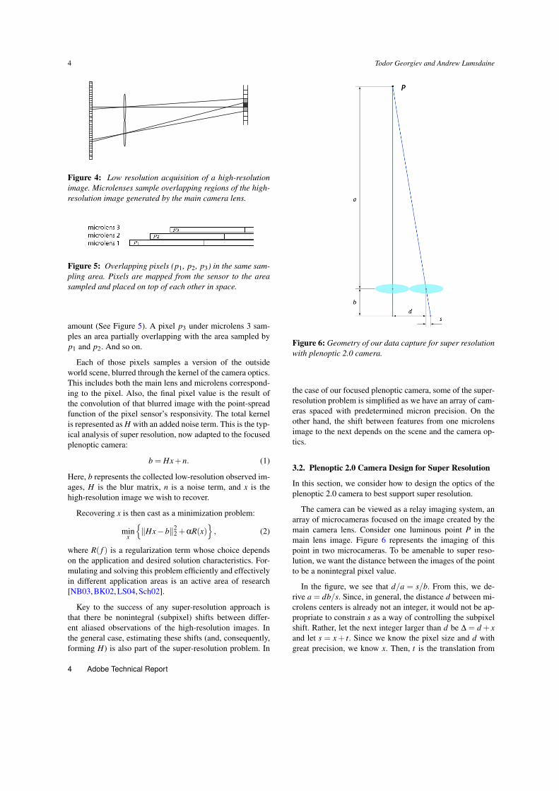
Figure 6: Geometry of our data capture for super resolutionwith plenoptic 2.0 camera.
the case of our focused plenoptic camera, some of the super-resolution problem is simplified as we have an array of cam-eras spaced with predetermined micron precision. On theother hand, the shift between features from one microlensimage to the next depends on the scene and the camera op-tics.
3.2. Plenoptic 2.0 Camera Design for Super Resolution
In this section, we consider how to design the optics of theplenoptic 2.0 camera to best support super resolution.
The camera can be viewed as a relay imaging system, anarray of microcameras focused on the image created by themain camera lens. Consider one luminous point P in themain lens image. Figure 6 represents the imaging of thispoint in two microcameras. To be amenable to super reso-lution, we want the distance between the images of the pointto be a nonintegral pixel value.
In the figure, we see that d/a = s/b. From this, we de-rive a = db/s. Since, in general, the distance d between mi-crolens centers is already not an integer, it would not be ap-propriate to constrain s as a way of controlling the subpixelshift. Rather, let the next integer larger than d be ∆ = d + xand let s = x + t. Since we know the pixel size and d withgreat precision, we know x. Then, t is the translation from
4 Adobe Technical Report

Superresolution with Plenoptic Camera 2.0 5
the integer pixel location to the image of the observed point.In this way, t = s− x is the quantity that we require to havea nonintegral value.
Note that there are multiple regions in the scene (multiplevalues of a and b) for which t will have a nonintegral value.For instance, we can take t to be 0.5 pixels, but we couldalso take it to be 1.5, or 2.5, or, in general, 0.5 + n for n =0,1,2,3, . . .. After super resolving, these provide the same2× increase in the resolution.
The general case is t = k + n, where k is a fraction lessthan 1. Different types of super resolution can be designedwith different k. With this notation, our general equation canbe written as
a =db
x+ k +n. (3)
Super resolution is achieved with microimages shifted by∆+ k +n pixels.
In the plenoptic 2.0 camera, the portion of the scene thatis at optical infinity (i.e., imaged at the largest distance fromthe microlenses) will have the greatest reduction in size. Thatis, the lowest spatial resolution under plenoptic 2.0 render-ing. At the same time, since it is the farthest from the mi-crolenses, it has the most angular samples. The low reso-lution and the availability of the most angular samples alsomeans that this region of the scene is the most important touse for support of super resolution.
Different depths in the scene are imaged at different dis-tances a in front of the microlenses. This creates a difficultyfor support of super resolution because the depths would su-per resolve at different values of k. Solving this problem re-quires subpixel registration among all microimages, whichmay be a difficult problem: The solution may be computa-tionally expensive or unreliable for automatic super resolu-tion. What’s more, certain depths would not be super resolv-able at all if the shift between microimages happens to beclose or equal to an integral number of pixels. This type ofproblem has plagued conventional super-resolution methodsfor years, and they still remain too unreliable for such com-mercial image-processing products as Adobe Photoshop, forexample.
However, the plenoptic 2.0 camera has a unique character-istic. There is one special depth in the scene, the depth of in-finity, that is always mapped to the same location in front ofthe microlenses, one focal length from the main camera lens.Infinity is also the depth that benefits most from plenoptic2.0 super resolution. This is also the depth that can be han-dled with highest precision for super resolution since it isfixed and subpixel correspondence is set and exactly knownin advance.
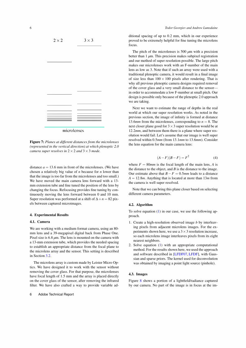
For a given type of super resolution (defined by the frac-tion k) there are a number of planes that satisfy the subpixelshift condition. As they approach the microlens array those
planes become denser and denser; at a certain point their po-sition becomes hard to determine and unreliable (see Figure7). The plane corresponding to infinity is the farthest fromthe microlens array at which there is image to capture. Theseparation between it and the previous one is the largest. Thismakes it the plane with most reliable correspondence, bestfor super resolution.
We design the camera such that infinity is super resolveddirectly, with registration provided by the camera geometryand the microlens pitch. This way we avoid estimation ofregistration from the imagery. At the same time our registra-tion is much more precise and reliable.
3.3. Specific Design Examples
The parameters of our physical plenoptic camera are as fol-lows. The microlens pitch is 500 µm and the sensor pix-els are 6.8 µm. Thus, d = 73.5294 pixels, ∆ = 74 pixels,and x = 0.4706 pixels. The value for b ≈ 1.6 mm could notbe estimated with precision better than 0.1 mm because ofthe cover glass of the sensor. We estimated it approximatelyfrom known sensor parameters and independently from themicrolens images at different F/numbers. In the end, wecomputed db ≈ 120mm. Note that a and b are measured inmillimeters while everything else is measured in pixels (i.e.no units).
3.3.1. 2 × 2 Super Resolution
Suppose we wish to super resolve a plenoptic 2.0 image in-creasing the size two times in each direction. For 2×2 superresolution, we need t = 0.5 + n, where n = 0,1,2,3, . . . anda = db/(x + 0.5 + n). With the parameters of our cameraabove, we have approximately a≈ 120/(1+n) measured inmillimeters. The values of n at which the camera super re-solves and the corresponding distances a (in millimeters) aregiven in the table below.
a 120 60 40 30 24 20 17.1 15 13.3 12 10.9 10 9.2n 0 1 2 3 4 5 6 7 8 9 10 11 12
3.3.2. 3 × 3 Super Resolution
If we want to super resolve a plenoptic 2.0 image threetimes in each direction, we need t = 1/3 + n, where n =0,1,2,3, . . . and a = db/(x + 1/3 + n). With the parametersof our camera above, we have approximately a≈ 120/(0.8+n) measured in millimeters.
a 150 66.6 42.8 31.6 25 20.7 17.6 15.4 13.6 12.2 11.1n 0 1 2 3 4 5 6 7 8 9 10
The depth planes at which the above two types of superresolution work are represented in Figure 7.
Other types of super resolution, such as 5× 5, and so on,can be designed easily.
The results in this paper are generated by selecting n = 8in the table for 3× 3 super resolution, corresponding to a
Adobe Technical Report 5
6 Todor Georgiev and Andrew Lumsdaine
Figure 7: Planes at different distances from the microlenses(represented in the vertical direction) at which plenoptic 2.0camera super resolves in 2×2 and 3×3 mode.
distance a = 13.6 mm in front of the microlenses. (We havechosen a relatively big value of n because for n lower thanthat the image is too far from the microlenses and too small.)We have moved the main camera lens forward with a 13-mm extension tube and fine tuned the position of the lens bychanging the focus. Refocusing provides fine tuning by con-tinuously moving the lens forward between 0 and 10 mm.Super resolution was performed at a shift of ∆+n = 82 pix-els between captured microimages.
4. Experimental Results
4.1. Camera
We are working with a medium format camera, using an 80-mm lens and a 39-megapixel digital back from Phase One.Pixel size is 6.8 µm. The lens is mounted on the camera witha 13-mm extension tube, which provides the needed spacingto establish an appropriate distance from the focal plane tothe microlens array and the sensor. This setting is describedin Section 3.2.
The microlens array is custom made by Leister Micro Op-tics. We have designed it to work with the sensor withoutremoving the cover glass. For that purpose, the microlenseshave focal length of 1.5 mm and the array is placed directlyon the cover glass of the sensor, after removing the infraredfilter. We have also crafted a way to provide variable ad-
ditional spacing of up to 0.2 mm, which in our experienceproved to be extremely helpful for fine tuning the microlensfocus.
The pitch of the microlenses is 500 µm with a precisionbetter than 1 µm. This precision makes subpixel registrationand our method of super resolution possible. The large pitchmakes our microlenses work with an F-number of the mainlens as low as 3. Note that if such an array were used with atraditional plenoptic camera, it would result in a final imageof size less than 100× 100 pixels after rendering. That iswhy all previous plenoptic camera designs required removalof the cover glass and a very small distance to the sensor—in order to accommodate a low F-number at small pitch. Ourdesign is possible only because of the plenoptic 2.0 approachwe are taking.
Next we want to estimate the range of depths in the realworld at which our super resolution works. As noted in theprevious section, the image of infinity is formed at distance13.6mm from the microlenses, corresponding to n = 8. Thenext closer plane good for 3×3 super resolution would be at12.2mm, and between them there is a plane where super res-olution would fail. Let’s assume that our image is well superresolved within 0.5mm (from 13.1mm to 13.6mm). Considerthe lens equation for the main camera lens:
(A−F)(B−F) = F2 (4)
where F = 80mm is the focal length of the main lens, A isthe distance to the object, and B is the distance to the image.Our estimate above that B−F = 0.5mm leads to a distanceA = 12.8m. Anything that is located at more than 13m fromthe camera is well super resolved.
Note that we can bring this plane closer based on selectingdifferent camera parameters.
4.2. Algorithm
To solve equation (1) in our case, we use the following ap-proach.
1. Create a high-resolution observed image b by interleav-ing pixels from adjacent microlens images. For the ex-periments shown here, we use a 3×3 resolution increase,so each microlens image interleaves pixels from its eightnearest neighbors.
2. Solve equation (1) with an appropriate computationalmethod. For the results shown here, we used the approachand software described in [LFDF07, LFDF], with Gaus-sian and sparse priors. The kernel used for deconvolutionwas obtained by imaging a point light source (pinhole).
4.3. Images
Figure 8 shows a portion of a lightfield/radiance capturedby our camera. No part of the image is in focus at the im-
6 Adobe Technical Report

Superresolution with Plenoptic Camera 2.0 7
Figure 8: A portion of the radiance recorded by our camera.
Figure 9: Extreme close up of a portion of the green rect-angle in Figure 8. The microimages are inverted and well-focused. The repeated image of an individual riding a bikecan be seen.
age plane, hence the lightfield image appears blurry at amacro level. However, if we closely examine the microim-ages themselves, we see a different story. They are well fo-cused, as shown in Figure 9, which is a zoom-in into thegreen rectangle. Note that for efficient use of sensor spacewe have installed a square main lens aperture, so our mi-croimages are squares and not circles.
Figure 10 shows a stereo rendering of the radiance ren-dered using the plenoptic 2.0 algorithm (without super reso-lution). To see the effects of different rendering approachesmore clearly, we consider smaller portions of the image. Tra-ditional lightfield rendering, with one pixel per microlens,yields an image with very low resolution, as shown inFigure 11. Alternatively, the plenoptic 2.0 (full resolution)rendering algorithm enables significant resolution improve-ment, as shown in Figure 12. A different view of the same
data rendered with the plenoptic 2.0 super resolution algo-rithm (as described in Section 4.2) is shown in Figure 13.
Figure 14 shows a close up of the front wheel of thebicycle when rendered with the plenoptic 2.0 algorithm—pixelation is obvious. Figure 15 shows a close up of thefront wheel of the bicycle when rendered with plenoptic 2.0and super resolution, using the algorithm described in Sec-tion 4.2.
Another example is the image of a bird on the antenna(Figure 1), which is a crop from a much bigger picture. Ifwe zoom in, we can clearly see pixelation in the plenoptic2.0 rendering and the improvement gained with our superresolution rendering.
The complete files of those images, as well as the inputlightfields we used, are available with the electronic versionof this paper.
5. Conclusion
The radiance (or plenoptic function) carries a significantamount of information. This information can be used to gen-erate novel effects when rendering. With the plenoptic 2.0camera, we are able to make deliberate spatio-angular trade-offs and obtain significant improvements in spatial resolu-tion. With the application of super-resolution techniques aspresented in this paper, we are able to push the attainablespatial resolution even further. One factor that has limitedthe adoption of plenoptic cameras until now has been therelatively low available resolution. The combination of thefocused plenoptic camera with super resolution enables im-ages of sizes acceptable to modern photographers, makinglightfield photography immediately practical.
References
[AW92] ADELSON T., WANG J.: Single lens stereo with aplenoptic camera. IEEE Transactions on Pattern Analysisand Machine Intelligence (1992), 99–106.
[BK02] BAKER S., KANADE T.: Limits on super-resolution and how to break them. IEEE Transactions onPattern Analysis and Machine . . . (January 2002).
[BS98] BORMAN S., STEVENSON R.: Super-resolutionfrom image sequences-a review. Proceedings of the 1998Midwest Symposium on Circuits and . . . (January 1998).
[BZF09] BISHOP T. E., ZANETTI S., FAVARO P.: Lightfield superresolution. In International Conference onComputational Photography (2009).
[EF97] ELAD M., FEUER A.: Restoration of a single su-perresolution image from several blurred, noisy, and un-dersampled measured . . . . Image Processing (January1997).
[FEW08] FIFE K., EL GAMAL A., WONG H.-S. P.: A3MPixel multi-aperture image sensor with 0.7 µm pixels
Adobe Technical Report 7

8 Todor Georgiev and Andrew Lumsdaine
Figure 10: A stereo pair rendered from our captured data (Figure 8) with the plenoptic 2.0 rendering algorithm. Intended forcrossed eye viewing (left and right image switched).
Figure 12: A view rendered from the same data with theplenoptic 2.0 (full resolution) rendering algorithm.
Figure 13: A slightly different view rendered from the samedata with our plenoptic 2.0 super resolution algorithm. Itincludes some of the white fence in the close foreground.
Figure 11: Portion of the same image rendered with thetrafitional (plenoptic 1.0) lightfield rendering algorithm.
Figure 14: Close up of the front wheel of the bicycle, usingplenoptic 2.0 rendering.8 Adobe Technical Report

Superresolution with Plenoptic Camera 2.0 9
Figure 15: Close up of the front wheel of the bicycle, usingplenoptic 2.0 rendering and super resolution.
in 0.11 µm CMOS. In IEEE ISSCC Digest of TechnicalPapers (February 2008), pp. 48–49.
[Hun95] HUNT B.: Super-resolution of images: algo-rithms, principles, performance. International Journal ofImaging Systems and Technology (January 1995).
[Ive28] IVES H. E.: A camera for making parallax panora-magrams. Journal of the Optical Society of America 17, 4(December 1928), 435–439.
[LFDF] LEVIN A., FERGUS R., DURAND
F., FREEMAN W.: Sparse deblurring code.http://groups.csail.mit.edu/graphics/CodedAperture.
[LFDF07] LEVIN A., FERGUS R., DURAND F., FREE-MAN W.: Image and depth from a conventional camerawith a coded aperture. ACM Transactions on Graphics,SIGGRAPH 2007 Conference Proceedings, San Diego,CA (2007).
[LG08] LUMSDAINE A., GEORGIEV T.: Full ResolutionLightfield Rendering. Tech. rep., Adobe Systems, January2008.
[LH96] LEVOY M., HANRAHAN P.: Light field rendering.Proceedings of the 23rd annual conference on ComputerGraphics and Interactive Techniques (January 1996).
[Lip08a] LIPPMANN G.: Épreuves réversibles donnant lasensation du relief. Journal of Physics 7, 4 (1908), 821–825.
[Lip08b] LIPPMANN G.: Épreuves réversibles. photogra-phies intégrales. Académie des sciences (March 1908),446–451.
[LS04] LIN Z., SHUM H.: Fundamental limits ofreconstruction-based superresolution algorithms under lo-cal translation. IEEE Transactions on Pattern Analysisand Machine Intelligence 26, 1 (January 2004), 83–97.
[NB03] NG M. K., BOSE N. K.: Mathematical analysisof super-resolution methodology. Signal Processing Mag-azine, IEEE 20, 3 (2003), 62–74.
[Ng06] NG R.: Digital light field photography. PhD the-sis, Stanford University, Stanford, CA, USA, 2006. Ad-viser: Patrick Hanrahan.
[NLB∗05] NG R., LEVOY M., BRÉDIF M., DUVAL G.,HOROWITZ M., HANRAHAN P.: Light Field Photogra-phy with a Hand-Held Plenoptic Camera. Tech. Rep.CSTR 2005-02, Stanford University Computer Science,Apr. 2005.
[Sch02] SCHULTZ R.: Super-resolution enhancement ofnative digital video versus digitized NTSC sequences. InProceedings of the Fifth IEEE Southwest Symposium onImage Analysis and Interpretation (2002), pp. 193–197.
[WJV∗05] WILBURN B., JOSHI N., VAISH V., TALVALA
E., ANTUNEZ E., BARTH A., ADAMS A., LEVOY M.,HOROWITZ M.: High performance imaging using largecamera arrays. In ACM Transactions on Graphics (2005).
Adobe Technical Report 9