supercap basic concept
TRANSCRIPT
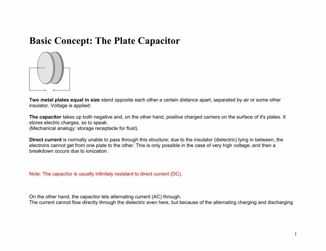
Basic Concept: The Plate Capacitor
Two metal plates equal in size stand opposite each other a certain distance apart, separated by air or some other insulator. Voltage is applied:
The capacitor takes up both negative and, on the other hand, positive charged carriers on the surface of it's plates. It stores electric charges, so to speak.(Mechanical analogy: storage receptacle for fluid).
Direct current is normally unable to pass through this structure; due to the insulator (dielectric) lying in between, the electrons cannot get from one plate to the other. This is only possible in the case of very high voltage, and then a breakdown occurs due to ionization.
Note: The capacitor is usually infinitely resistant to direct current (DC).
On the other hand, the capacitor lets alternating current (AC) through.The current cannot flow directly through the dielectric even here, but because of the alternating charging and discharging
1
of the plates, charged carriers appear to be transported through the capacitor.Of course, the capacitor presents some resistance to alternating current too, this is dependent on the frequency.
Note: At lower frequencies the capacitive resistance is higher. At higher frequencies the capacitive resistance is lower.
2

Dielectric In reality the dielectric is not an ideal insulator, i.e. a certain number of electrons penetrate it.
Due to these processes and also to changing polarization in the material, part of the electric energy is lost as dissipated heat:
a)
Ohmic losses: there is a difference between insulation resistance = volume resistance Rv (current flow through the interior of the insulator) and surface resistance = the external resistance Rs (current flow over the surface of the insulator due to humidity or dirt). Together they make up the complete resistance
The ohmic losses are to be seen in the rise of the temperature of the insulator which is often quite considerable. b) Dielectric losses (dissipation) are the result of the changing polarization of the elementary particles of the dielectric caused by alternating fields.They are transformed into oscillations (like little compass needles) and thus produce frictional heat. So, here too, part of
the electric energy is lost in heat. The losses amount to:
tan is the dissipation factor, it is the measurement of dielectric losses and is dependent on frequency.
3

CapacitanceDefinition: A capacitor is measured by the size of its capacitance. A capacitance is the electric capacity of a capacitor, i.e. the amount of electrically charged carriers it can store. Symbol: C
Measurement unit: F = farad Calculation example: The capacitance is 1 farad when a current of 1 ampere flows for one second with the applied voltage of 1 V.
The stored charge Q is proportional to the applied voltage U.
Q ~ U
The proportional factor C is the capacitance of the capacitor
Q = C x U
Capacitance calculation for the plate capacitor
4
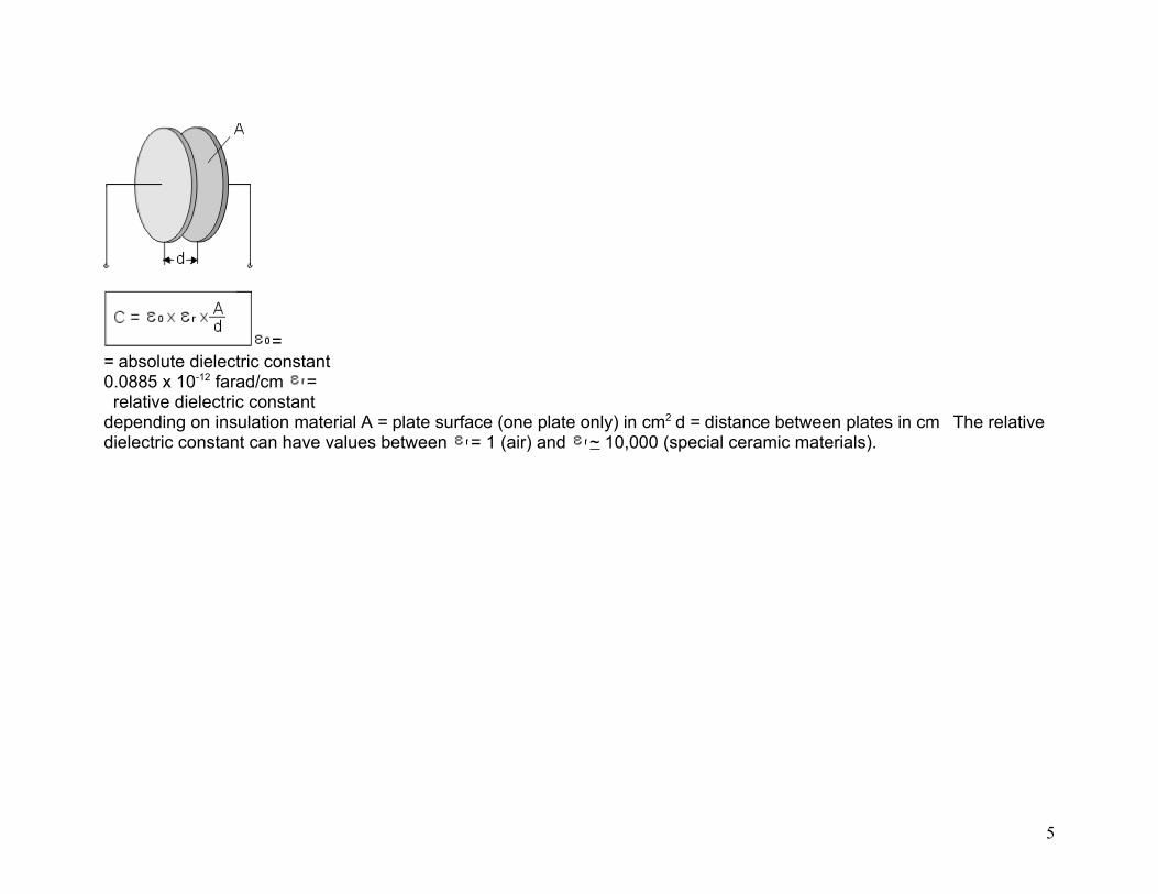
== absolute dielectric constant0.0885 x 10-12 farad/cm =. relative dielectric constantdepending on insulation material A = plate surface (one plate only) in cm2 d = distance between plates in cm The relative dielectric constant can have values between = 1 (air) and ~ 10,000 (special ceramic materials).
5

Capacitance Tolerance Tolerance is the permissible relative deviation of the capacitance from the rated value, expressed in per cent. The tolerance is to be measured at a temperature of +20°C and is only valid at the time of delivery.
After a longer period of storage or use, the tolerance can increase; but, according to standard specification, it may never exceed twice the value measured at the time of delivery.
The following delivery tolerances are usual for wound capacitors:
±1%; ±2.5%; ±5%; ±10%; ±20%.
In the case of electrolytic capacitors for which the largest possible capacitance matters, tolerances of +100/-20% also occur.
Note: The tolerance (with the exception of 20%) is usually clearly marked on the body of the capacitor, in case of very small capacitor sizes, coding or ciphers according to IEC 60062 are also used.
Rated Voltage
6

Each capacitor is designed for a particular rated voltage, which it must stand up to without adverse effect during continuous operation.
However, this only applies to ambient temperatures of < +85°C; at higher temperatures the maximum permissible voltage or voltage limit for continuous operation is reduced by voltage derating.
This is caused by tiny weak points in the dielectric, which, under increased temperatures, are subject to greater stress and can then break down.
In the case of rated voltage, DC voltage specifications are distinguished from AC voltage data. In general, this information is printed on the capacitor with clear symbols; in the case of capacitors with very small dimensions code symbols may be necessary as with the tolerance specifications.
Voltage DeratingWith all thermoplastic film dielectrics, the voltage strength diminishes when the temperature is increased.
The voltage derating gives the percentage by which the permissible voltage is reduced compared to the rated voltage, for DC voltage operation from +85°C and for AC voltage operation from +75°C, at a temperature increase of 1K.
Insulation ResistancePaper and plastic film capacitors usually have insulation resistance values ranging from 6000 to 12000 M .
7
The insulation resistance is given in Ohm. This is not quite explicit because the insulation resistance changes for a time after voltage is applied - the self-discharge constant = Ris x C is also used to measure the quality of the insulation.
The time constant gives the time in seconds during which the voltage between the terminating wires of a charged capacitor decreases to 37% due to self-discharging.
With capacitance values in the µF range, the time constant at the time of delivery is usually between 2000 and 4000 seconds.
Humidity which penetrates into the capacitor winding, lowers the insulation resistance.An appropriately thick casing should therefore be provided, according to how much humidity the capacitor will be subjected to.
Good insulation resistance is necessary for capacitors which are used to block off DC voltage and for storage capacitors in which a particular voltage rate has to remain unchanged for a longer period of time.
Dissipation Factor and ESRThe dissipation factor tan is the quotient of the active and reactive components of the impedance.
8

The losses occur mainly in the dielectric and are represented by R in the equivalent circuit diagram.Parallel to R is the insulation resistance Ris, which, in fact, only affects tan at very low frequencies.
Further dissipation is caused by the finite conductivity of the electrodes and the transfer resistance between the electrodes and the terminating wires.
This is represented in the equivalent circuit diagram by the series resistance r.L represents the remaining self-inductance.
Values of ESR are not directly stated in the data sheets of plastic film capacitors. The ESR for an individual capacitance value C can be calculated by the formula
ESR = tan x (2 x x f x C)-1
tan : see data sheetsf: frequency of the AC voltage share in the application.
Inductance and Self-Resonance
9

Depending on the construction, an alternating current in the capacitor winding creates a more or less distinctive magnetic field which can be measured as inductance L (see equivalent circuit diagram).
The self-inductance L of modern capacitors - reduced by structural measures (e.g. contact over the end surfaces) - is approximately 10 nH. It is therefore not greater than the inductance of a wire, which is as long as the capacitor leads plus
the lead spacing. L and C form a series oscillating circuit; at a frequency of the capacitor is in self-resonance and has the lowest impedance, which only consists of r (ESR equivalent series resistance).
Temperature Coefficient (TKc)
The temperature coefficient shows the fraction by which the capacitance, measured at +20°C, changes when the surrounding temperature rises by 1 degree C.
10
C20 = capacitance at +20°CCT = capacitance at T°C can be positive or negative. In the case of good capacitors the TKc is in the region of just a few 10-5/°C. TKc 10-5/°C = 10 x 10-6/°C = 10 ppm/°C
Pulse Stressing In the case of metallized capacitors the user has to give guidelines for the maximum possible pulse stressing because of the limited current capacity of electrodes and contacts.
These guidelines are worked out by means of so-called pulse tests, in which the stress which might occur during application, is simulated.
In a test circuit in accordance with IEC 60384 part 1, the test specimen is charged and then discharged intermittently. The test voltage corresponds to the rated DC voltage and the test comprises 10000 pulses with a repetition frequency of 1 Hz.
The pulse stress capacity is given as pulse rise time in V/µsec. The stipulations for individual capacitor series are in accordance with the CECC type specifications. The rated or operational pulse rise time is specified as 1/10 of the test pulse rise time.
The pulse rise time F given in V/µsec is also indirectly the maximum current capacity.
11
C in µFI in A The values on the pulse rise time refer to pulses equal to the full rated voltage, so that, at lower operating voltages the permissible pulse rise times may also be increased.
Long Term Stability / Temporal Inconstancy Environmental influences such as heat, high humidity and strong mechanical vibrations can, over a longer period of time, due to ageing, lead to an irreversible change in the capacitance value.
The information about the temporal inconstancy lays down the maximum extent to which the capacitance of a capacitor may change under the influence of environmental factors.
As a rule, temporal inconstancy is given in %. The period of time specified by the relevant standards is 2 years, based on a regular temperature of +40°C. Changes after two years are virtually of no importance.
Typical values are, for example, ±3% for KT-/MKT capacitors and ±0.5 or ±1% for KP-/MKP capacitors according to type.
Dielectric Absorption
12

A capacitor which has been charged for a long time and then been completely discharged, has a small voltage on its terminal wires again, within seconds or minutes.This effect is known as dielectric absorption.
This phenomenon has a particularly unfavorable effect in sample and hold applications in which charges are to be stored for comparision/measuring purposes.
The recharging comes from polarization processes in the insulating material and is largely independent of the capacitance of the capacitor and the thickness of the dielectric.
Measuring of Dielectric Absorption
The standard MIL-C-19978 describes the measuring method of the dielectric absorption.
Circuit diagram:
13
The capacitor Cx is charged for 15 minutes on a reference DC voltage, e.g. up to the rated DC voltage of the capacitor. The initial current surge may not exceed 50 mA.
At the end of the charging time the capacitor is separated from the charging source and discharged over a resistance of 50 . The discharging resistance is removed from the capacitor after 10 sec.
The "regained voltage" is measured after a period of 15 minutes with a high ohmic (Ri > 10000 M ) millivoltmeter.
The dielectric absorption DA can be calculated according to the following formula:
DA = U1 / U2 x 100%
DA = dielectric absorptionU1 = regained voltageU2 = charging voltage
Typical values of some dielectrics in % at T = +23°C:
- Polypropylene- Polyester- Mixed dielectric- Ceramic (X7R)- Ceramic (Z5U) 0.05 ... 0.100.20 ... 0.250.12 ... 0.180.60 ... 1.002.00 ... 2.50
14
Reliability
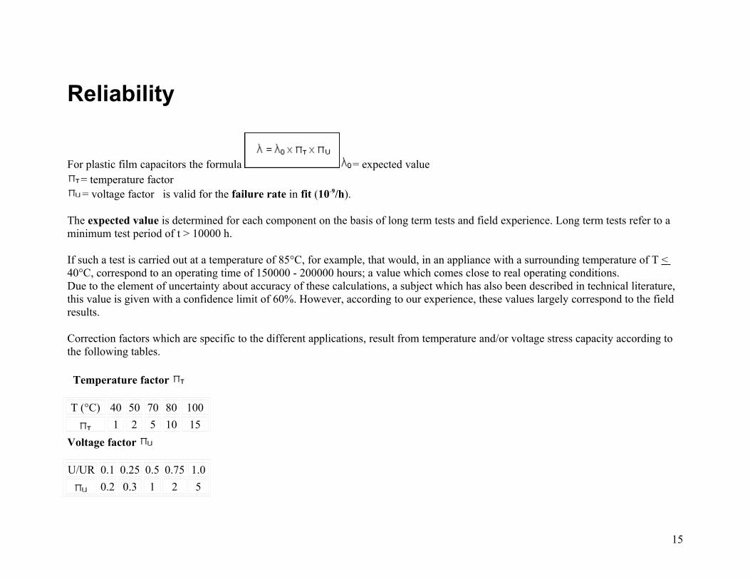
For plastic film capacitors the formula = expected value= temperature factor= voltage factor is valid for the failure rate in fit (10-9/h).
The expected value is determined for each component on the basis of long term tests and field experience. Long term tests refer to a minimum test period of t > 10000 h.
If such a test is carried out at a temperature of 85°C, for example, that would, in an appliance with a surrounding temperature of T < 40°C, correspond to an operating time of 150000 - 200000 hours; a value which comes close to real operating conditions.Due to the element of uncertainty about accuracy of these calculations, a subject which has also been described in technical literature, this value is given with a confidence limit of 60%. However, according to our experience, these values largely correspond to the field results.
Correction factors which are specific to the different applications, result from temperature and/or voltage stress capacity according to the following tables.
Temperature factor
T (°C) 40 50 70 80 100
1 2 5 10 15
Voltage factor
U/UR 0.1 0.25 0.5 0.75 1.0
0.2 0.3 1 2 5
15

Today metallized plastic film capacitors with Polyester film achieve the best values.
Here the expected value is about 2 fit. This results in a failure rate of 10 fit.
Example: WIMA MKS 2 / 0.1 µF / 63 VDC
= 2 fit= 1= 5
= 2 x 5 x 1 = 10 fit
The expected values for other types of capacitors are available on request.
Warning Notice / Technical Support AC Voltage Load at the Mains
Anticipating possible interfering pulses, DC voltage capacitors must not be operated at the mains (line power), irrespective of the rated AC voltage. For this purpose, use approved electromagnetic interference suppression capacitors only.
Thermal Load in the Application
If a plastic film capacitor is overstressed due to inappropriate usage under AC voltage conditions, the temperature inside the component may rise to an impermissibly high level. Thus, the dielectric film may subsequently be damaged leading to
16

a short circuit or formation of smoke and even fire in the capacitor. It may also happen if the capacitor is overheated by an external heat source.
Shock and/or Vibration Load for Larger Case Sizes
For increased shock and vibration applications involving larger case sizes (i.e., PCM 22.5 mm lead spacing or greater), it is recommended to fix capacitors in an appropriate way; or special lead and tab terminations may be required respectively, to minimize lead separation from the capacitor element or the solder joint.
Processing
When processing plastic film capacitors it is mandatory to observe the application recommendations with regard to soldering and/or cleaning and drying processes.
General Remarks
All data, range surveys and application data correspond to the actual state of the art and were elaborated as thoroughly and precisely as possible. They are to be understood as general information, and the right for amendments and construction changes is reserved. Special customized designs which deviate from our catalogue data, irrespective of
17

whether being based on factory standards, specifications or related data, do not release the user from his duty of care with regard to incoming goods inspection and production monitoring. In case of the components being purchased through second or third suppliers we urgently ask to compare the technical details with the data given by the manufacturer. In cases of doubt we recommend use is made of our technical support, since we do not take any responsibility for damages caused by inappropriate use or processing of our capacitors.
18

Construction of Plastic Film Capacitors:
The film/foil construction is mainly used for capacitors with smaller capacitance (100pF through 0.1µF).
The advantage of this construction is the easy contactability of the metal foil electrodes and the good pulse strength.
A breakdown in the dielectric film of a F capacitor leads to an irreversible short circuit and thus, to failure.
To avoid breakdowns caused by weak spots in the dielectric, the insulating film chosen is always thicker than theoretically required by the values which are determined from the specific breakdown strength of the material. Films of less than 4 µm are not used for F capacitors because of their high proportion of weak points.The necessity for thicker insulating film has an unfavorable effect on the size and the material used. In order to achieve a particular capacitance with thicker insulating film, the length of the band also has to be increased by the same amount. Thicker insulating film therefore squares the volume of the winding element.
A weak spot occurs, when depressions meet on the upper and lower surfaces of the film. The dielectric must then be at least thick enough to have just the required breakdown strength.
Advantage: High pulse loading capacity due to good contact of the terminating wires to the metal foil electrodes.
19

WIMA types with film/foil construction
Metallized Construction The metallized type of construction also makes it possible to produce wound capacitors with larger capacitance values in small sizes (~ 0.01µF through 100µF and larger). In the case of M capacitors, thin layers of aluminium (~ 0.03µm) are vacuum-deposited on the insulating film as conducting electrodes. In the case of a breakdown, the short circuit current causes the thin metal coating to evaporate around the point of failure, without reducing the quality of the dielectric. An insulating area is formed, the capacitor remains intact (self-healing). The capacitance loss of a few pF which this causes, is of no importance.
With metallized capacitors, the breakdown strength of the insulating film can be used to the full. During the production of the capacitors the weak points are burnt out. This makes it possible to use the thinnest insulating films right down to < 1µm in thickness.
In contrast to the advantages of the small dimensions and the self-healing properties of metallized capacitors, there is the disadvantage of a limited current loading capacity as a result of the thin, vacuum-deposited metal layers.
Advantage: Construction with the most favorable capacitance/volume value.
WIMA types with metallized construction:
20

21

Metallized Construction for Pulse Applications
-63VAC, 180VAC, 250VAC-180VAC, 250VAC-180VAC, 250VAC
22

-400VAC, 600VAC, 650VAC, 700VAC
-400VAC, 700VAC-400VAC, 450VAC, 500VAC, 550VAC
-900VAC/PCM 22.5mm (PCM 15mm = 3-section)
In order to counter the disadvantage of the limited current loading capacity of single-sided metallized capacitors, WIMA has developed special metallized versions for high pulse applications, in which the electrodes are not directly metallized on the dielectric film. Aluminium is vacuum-deposited on both sides of a thin plastic film and this film is rolled up along with the insulating film as is the case with a film/foil capacitor.
With schoopage (metal flame spraying) and contacting, the two metal layers on the carrier film are joined together as a conductor. The carrier film is therefore in fieldfree space, its dielectric properties are of no importance, ("film in fieldfree space") and the self-healing process in breakdowns takes place on this film. Thanks to the metallization on both sides, this type has the same good self-healing properties as a capacitor which is metallized on one side only, the conducting capacity of a double thickness metallized layer and the advantage of better contacts.
23
These capacitors can stand up to very high pulse currents and have only a slightly larger volume than single-sided metallized capacitors. They offer high operating safety in critical applications.
Advantages:High pulse loading capacity due to good contacting of the metal layers with schoopage.Good self-healing properties thanks to the carrier film in fieldfree space.
24
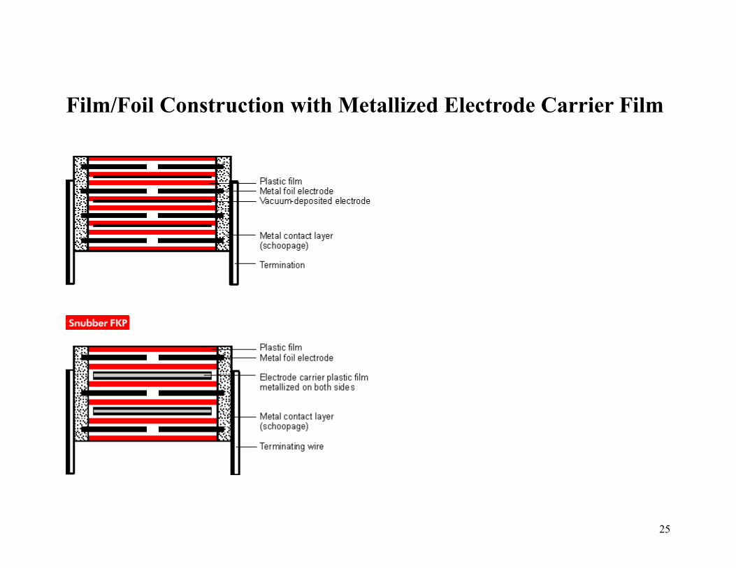
Film/Foil Construction with Metallized Electrode Carrier Film
25

Due to its film/foil structure with metallized electrode carrier, this capacitor type is suitable for highest current loads.
The capacitor is constructed as a series connection, the current carrying electrodes consist of two metal foils and a metallized carrier film as a "floating electrode".
After schoopage and bonding the wires are connected with all the edges of the winding element. The floating electrode only carries current through capacitive coupling. In this way, the advantage of self-healing (by means of the metallized floating electrode) is combined with the advantage of the exceptionally safe bonding of the metal foil.Thanks to the series connection, the value of the corona inception voltage is doubled.
Capacitors constructed in this way are suitable for very high rated currents with a maximum of operating safety.
Advantages:Highest pulse loading capacity due to very good bonding (metal foil electrode and metallized electrode carrier film).Good self-healing properties thanks to the metallized carrier film floating electrode.Due to the series connection, the value of the corona inception voltage is doubled.
26

Self-healing Process in Metallized Capacitors
Even the best plastic films, like ceramic materials, are not free from pin-holes.However, in the case of metallized film capacitors it is possible to eliminate these faults by applying a much higher voltage than the rated voltage. This process is known as self-healing and practically makes a "zero defect dielectric" possible.
Figure 1: Schematic representation of the self-healing process
27

Figure 2: Isolated area after the self-healing process
The self-healing process is started by an electric breakdown, which takes about 10-8 secs. In the breakdown channel, the dielectric is transformed into a highly compressed plasma which is pushed out of the channel and presses the dielectric layers apart (figure 1).
In the spreading plasma, discharging continues over the metal electrodes. Temperatures of approximately 6000 K occur and insulated areas are formed around the original failure spot (figure 2). This self-healing process takes a few µsec and the discharging in the plasma has already ceased before a greater loss of voltage takes place. This quick extinction of the plasma is necessary to avoid further damage to the dielectric layer next to the point of failure.The pressure between the layers must not be too great, so that the plasma can spread out from the breakdown channel quickly. Large parts of the plasma get into areas of low field strength.
The flawless course of the self-healing process depends on the thickness of the metallization, on the chemical composition and on the rate of the applied voltage; here, apart from the chemical composition, the production conditions have to provide the prerequisites for optimum self-healing.
Self-healing behaviour as a quality standard.
The capacitors manufactured by WIMA in winding technology are produced as single winding capacitors. The most effective pressure on the layers necessary for good self-healing behaviour can be individually adjusted for each capacitor.
WIMA capacitors are known for their excellent self-healing behaviour.
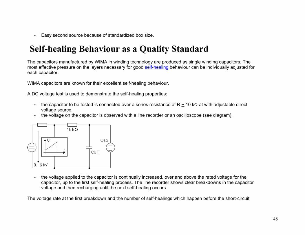
A DC voltage test is used to demonstrate the self-healing properties:
28

• the capacitor to be tested is connected over a series resistance of R ~ 10 k at with adjustable direct voltage source.
• the voltage on the capacitor is observed with a line recorder or an oscilloscope (see diagram).
• the voltage applied to the capacitor is continually increased, over and above the rated voltage for the capacitor, up to the first self-healing process. The line recorder shows clear breakdowns in the capacitor voltage and then recharging until the next self-healing occurs.
The voltage rate at the first breakdown and the number of self-healings which happen before the short-circuit finally occurs, allow definite conclusions to be drawn about the capacitor dimensioning or type.This clearly shows that stacked MKT film capacitors short-circuit after a few self-healing processes. Also, the rate of the breakdown voltage is usually distinctly lower. A low loading capacity and a reduced life time are the result.
WIMA capacitors, on the other hand, are surprisingly hardy. As well as having very high breakdown voltage, they self-heal much more frequently than corresponding stacked film capacitors. The test clearly proves the high reliability and long life-span of WIMA MKS capacitors, well above the data given in the catalogue.
29
Dielectric:
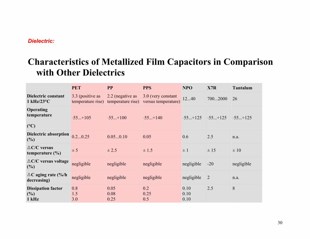
Characteristics of Metallized Film Capacitors in Comparison with Other Dielectrics
PET PP PPS NPO X7R Tantalum
Dielectric constant1 kHz/23°C
3.3 (positive as temperature rise)
2.2 (negative as temperature rise)
3.0 (very constant versus temperature)
12...40 700...2000 26
Operating temperature
(°C)
_55...+105 _55...+100 _55...+140 _55...+125 _55...+125 _55...+125
Dielectric absorption(%)
0.2...0.25 0.05...0.10 0.05 0.6 2.5 n.a.
C/C versus temperature (%)
± 5 ± 2.5 ± 1.5 ± 1 ± 15 ± 10
C/C versus voltage (%)
negligible negligible negligible negligible -20 negligible
C aging rate (%/h decreasing)
negligible negligible negligible negligible 2 n.a.
Dissipation factor (%)1 kHz
0.81.53.0
0.050.080.25
0.20.250.5
0.100.100.10
2.5 8
30

10 kHz100 kHz
ESR low very low very low low moderate high
Ris (M x µF)25 °C85 °C
100001000
10000010000
100001000
100001000
1000500
10010
Capacitance range from pF to µF
1000...220 27...100 10000...6.8 1...0.1 100...2.2 100000...1000
Capacitance tolerance(+/- %)
5/10/20 1/2.5/5/10 2.5/5/10/20 5/10 10/20 10/20
Self-healing yes yes yes no no no
Typical failure mode at end of life
open open open short short short
Reliability high high high high moderate low
Piezoelectric effect no no no yes yes yes
Resistance to thermal and mechanical shock
high high highmoderate to low
moderate to low
high
Polarity no no no no no yes
-
31

Polyester (Polyethylene-terephthalate)
Basic Molecule
Typical Graphs
Capacitance change versus temperature
(f = 1 kHz) ( general guide)
32
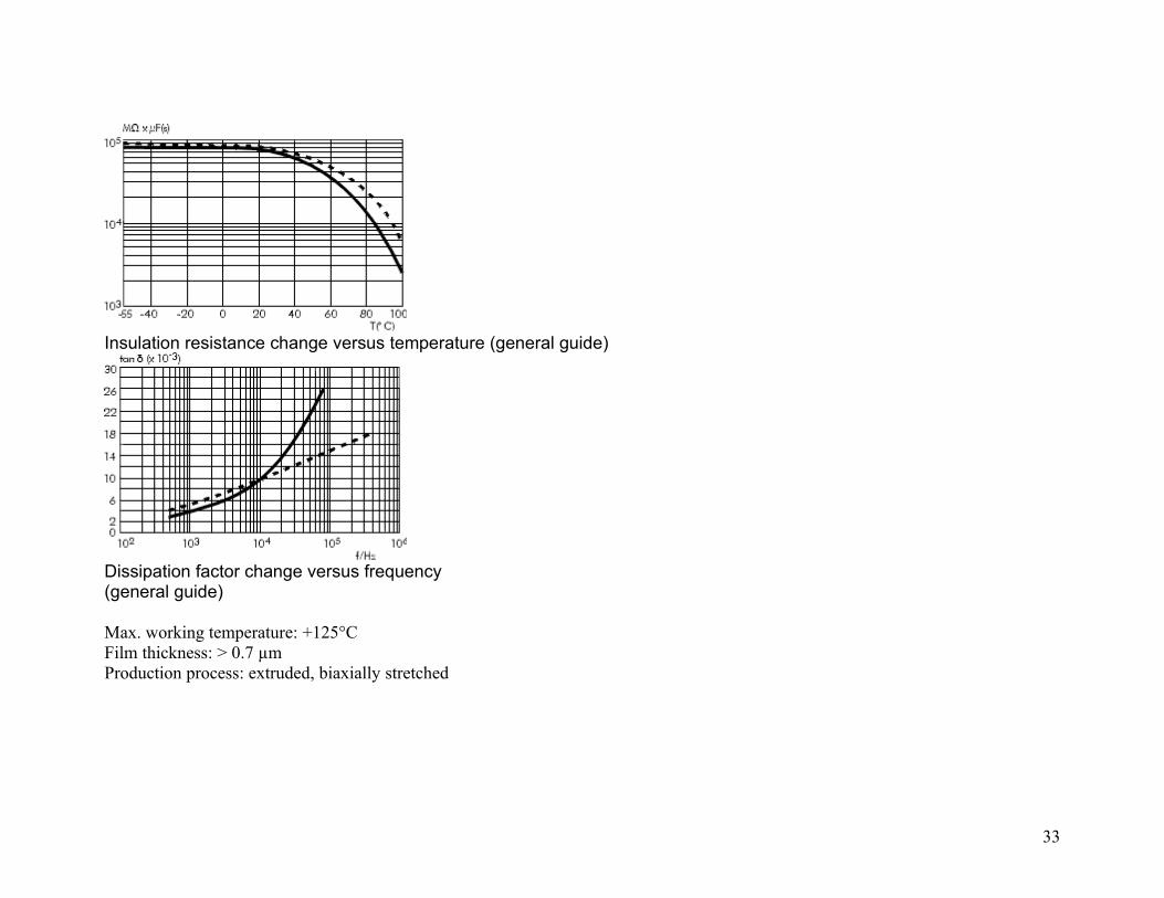
Insulation resistance change versus temperature (general guide)
Dissipation factor change versus frequency(general guide)
Max. working temperature: +125°CFilm thickness: > 0.7 µmProduction process: extruded, biaxially stretched
33
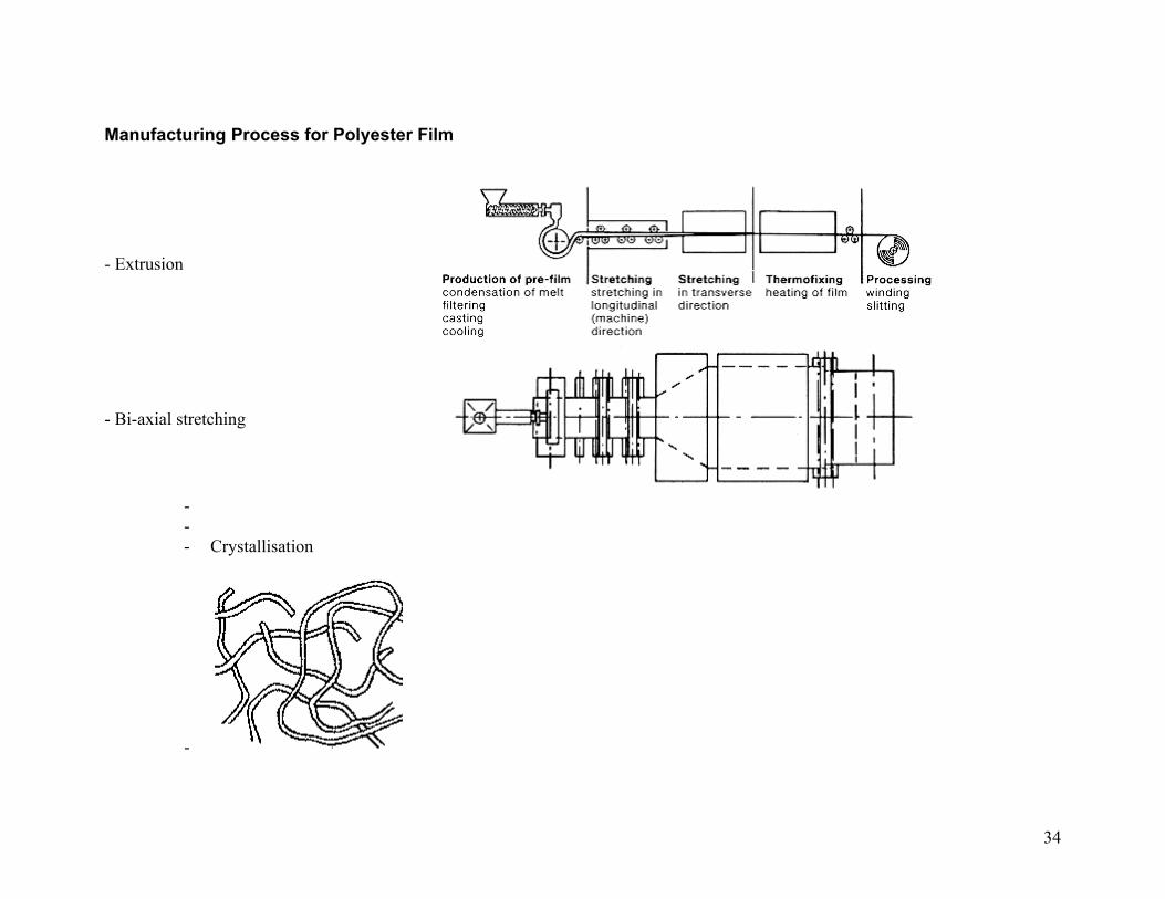
Manufacturing Process for Polyester Film
- Extrusion
- Bi-axial stretching
--- Crystallisation
-
34
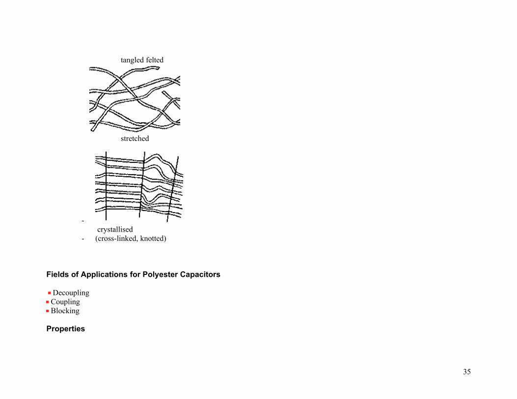
tangled felted
stretched
- crystallised
- (cross-linked, knotted)
Fields of Applications for Polyester Capacitors
Decoupling Coupling Blocking
Properties
35

Advantageous price/performance ratioAdvantageous capacitance/volume ratioSubstitution of low quality electrolytic and tantal capacitors
Polypropylene Basic Molecule
Typical Graphs
Capacitance change versus temperature
(f = 1 kHz) ( general guide)
36

Insulation resistance change versus temperature (general guide)
Dissipation factor change versus frequency(general guide)
Max. working temperature: +100°C
Film thickness: > 4 µm
Production process: extruded, biaxially stretched
37
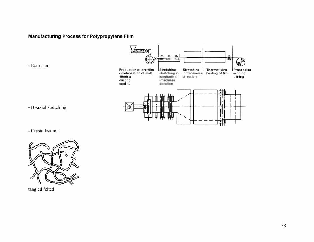
Manufacturing Process for Polypropylene Film
- Extrusion
- Bi-axial stretching
- Crystallisation
tangled felted
38
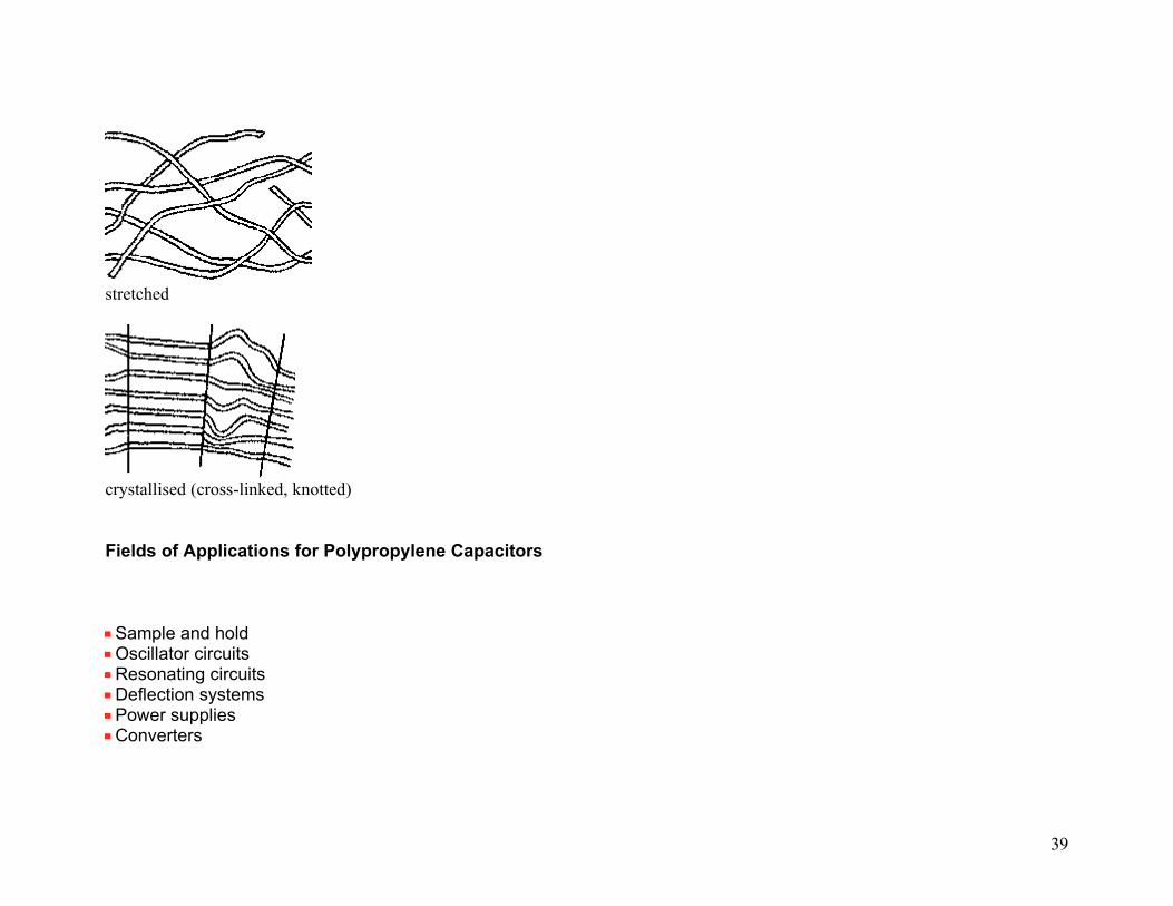
stretched
crystallised (cross-linked, knotted)
Fields of Applications for Polypropylene Capacitors
Sample and holdOscillator circuitsResonating circuitsDeflection systemsPower suppliesConverters
39
LightingAudio applications
Properties
Lowest dissipation factorConstantly negative TKcClose tolerances up to 1%
40

MP (Metallized Paper)
Properties
Capacitance change versus temperature(f = 1 kHz) ( general guide)
Insulation resistance change versus temperature(general guide)
41
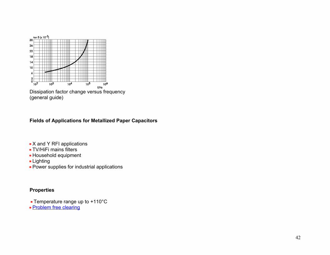
Dissipation factor change versus frequency(general guide)
Fields of Applications for Metallized Paper Capacitors
X and Y RFI applicationsTV/HiFi mains filtersHousehold equipmentLightingPower supplies for industrial applications
Properties
Temperature range up to +110°CProblem free clearing
42
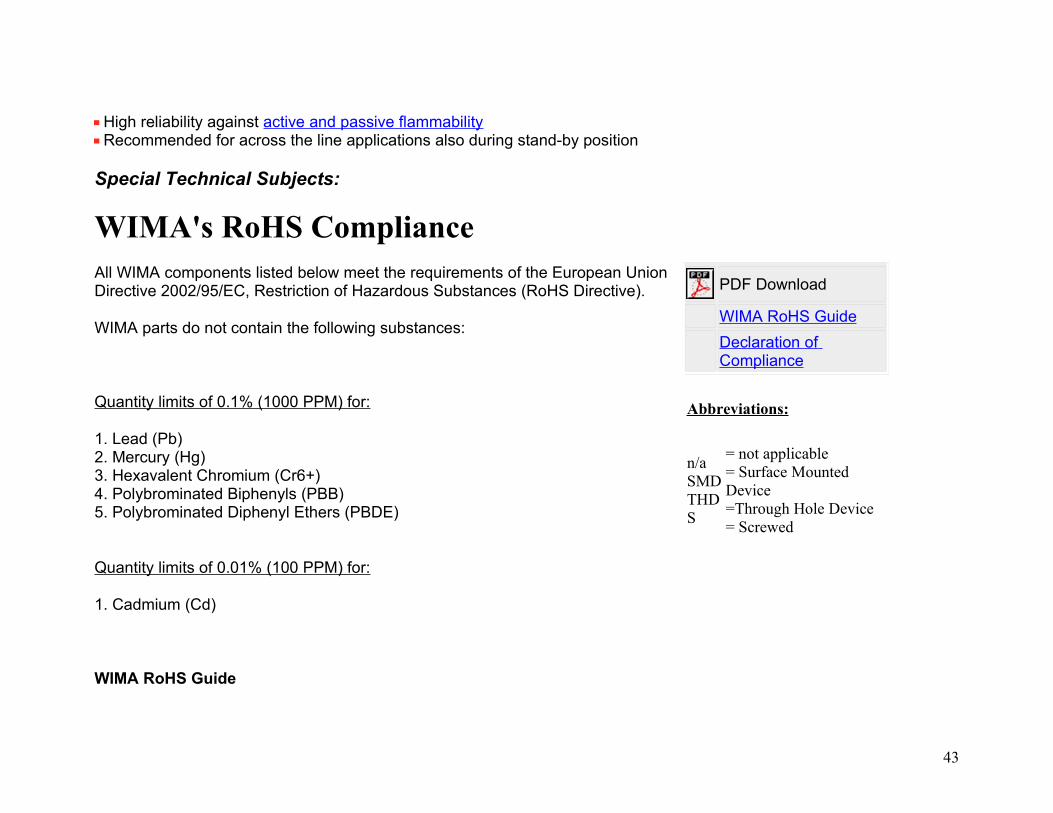
High reliability against active and passive flammabilityRecommended for across the line applications also during stand-by position
Special Technical Subjects:
WIMA's RoHS Compliance All WIMA components listed below meet the requirements of the European Union Directive 2002/95/EC, Restriction of Hazardous Substances (RoHS Directive).
WIMA parts do not contain the following substances:
Quantity limits of 0.1% (1000 PPM) for:
1. Lead (Pb)2. Mercury (Hg)3. Hexavalent Chromium (Cr6+)4. Polybrominated Biphenyls (PBB)5. Polybrominated Diphenyl Ethers (PBDE)
Quantity limits of 0.01% (100 PPM) for:
1. Cadmium (Cd)
WIMA RoHS Guide
PDF Download
WIMA RoHS Guide
Declaration of Compliance
Abbreviations:
n/aSMDTHDS
= not applicable= Surface Mounted Device=Through Hole Device= Screwed
43
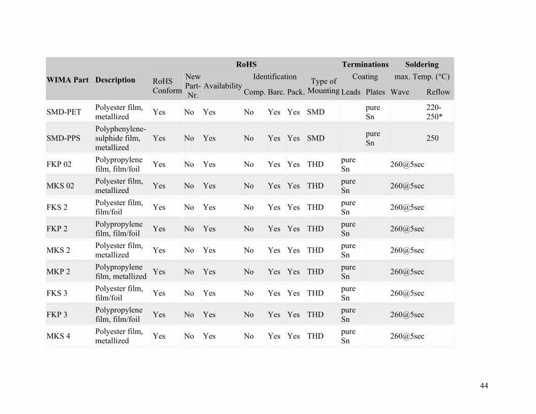
WIMA Part Description
RoHS Terminations Soldering
RoHSConform
New Part-Nr.
AvailabilityIdentification
Type ofMounting
Coating max. Temp. (°C)
Comp. Barc. Pack. Leads Plates Wave Reflow
SMD-PETPolyester film, metallized
Yes No Yes No Yes Yes SMD pure Sn
220-250*
SMD-PPSPolyphenylene-sulphide film, metallized
Yes No Yes No Yes Yes SMD pure Sn
250
FKP 02Polypropylene film, film/foil
Yes No Yes No Yes Yes THDpure Sn
260@5sec
MKS 02Polyester film, metallized
Yes No Yes No Yes Yes THDpure Sn
260@5sec
FKS 2Polyester film, film/foil
Yes No Yes No Yes Yes THDpure Sn
260@5sec
FKP 2Polypropylene film, film/foil
Yes No Yes No Yes Yes THDpure Sn
260@5sec
MKS 2Polyester film, metallized
Yes No Yes No Yes Yes THDpure Sn
260@5sec
MKP 2Polypropylene film, metallized
Yes No Yes No Yes Yes THDpure Sn
260@5sec
FKS 3Polyester film, film/foil
Yes No Yes No Yes Yes THDpure Sn
260@5sec .
FKP 3Polypropylene film, film/foil
Yes No Yes No Yes Yes THDpure Sn
260@5sec
MKS 4Polyester film, metallized
Yes No Yes No Yes Yes THDpure Sn
260@5sec
44

MKP 4Polypropylene film, metallized
Yes No Yes No Yes Yes THDpure Sn
260@5sec
MKP 10
Polypropylene film, double metallized electrode
Yes No Yes No Yes Yes THD
pure Sn
260@5sec
FKP 4
Polypropylene film, metal foil/metallized film
Yes No Yes No Yes Yes THD
pure Sn
260@5sec
FKP 1
Polypropylene film, metal foil/double metallized film
Yes No Yes No Yes Yes THD
pure Sn
260@5sec
MKP-X2Polypropylene film, metallized
Yes No Yes No Yes Yes THDpure Sn
260@5sec
MKP-X2 R Polypropylene film, metallized
Yes No Yes No Yes Yes THDpure Sn
260@5sec
MKP-Y2Polypropylene film, metallized
Yes No Yes No Yes Yes THDpure Sn
. 260@5sec
MP 3-X2 Paper, metallized Yes No Yes No Yes Yes THDpure Sn
. 260@5sec
MP 3-X1 Paper, metallized Yes No Yes No Yes Yes THDpure Sn
. 260@5sec
MP 3-Y2 Paper, metallized Yes No Yes No Yes Yes THDpure Sn
. 260@5sec
MP 3R-Y2 Paper, metallized Yes No Yes No Yes Yes THDpure Sn
. 260@5sec
45

SnubberMKP
Polypropylene film, double metallized electrode
Yes No Yes No Yes Yes THD/Spure Sn
pure Sn
260@5sec
SnubberFKP..
Polypropylene film, metal foil/metallized film
Yes No Yes No Yes Yes THD/S
pure Sn
pure Sn
260@5sec
GTO MKP
Polypropylene film, double metallized electrode
Yes No Yes No Yes Yes S n/a n/a
DC-LINK MKP 4
Polypropylene film, metallized
Yes No Yes No Yes Yes THD/Spure Sn
pure Sn
260@5sec
DC-LINK MKP C
Polypropylene film, metallized
Yes No Yes No Yes Yes S n/a n/a
DC-LINK HC Polypropylene film, metallized
Yes No Yes No Yes Yes S n/apure Sn
n/a
SuperCap C Double layer Yes No Yes No Yes Yes n/a n/a n/a
SuperCap MC Double layer, cascaded
Yes No Yes No Yes Yes n/a n/a n/a
SuperCap R Double layer, cascaded
Yes No Yes No Yes Yes n/a n/a n/a
SuperCap MR Double layer Yes No Yes No Yes Yes n/a n/a n/a
* depending on size code
Rights reserved to amend design data without prior notification.
46

Encapsulation of WIMA Capacitors
Both, SMD and through-hole WIMA DC capacitors are produced with the proven box technology, showing the following substantial advantages in comparison with non-encapsulated, moulded or dipped capacitor versions:
• Safe protection of the capacitor element against the mechanical stresses which occur during processing and operation.
• No danger of delamination, internal cracks or tearing away of the contacts due to similar expansion coefficient and the elasticity of the construction.
• Excellent self-healing properties of metallized WIMA capacitors due to pressure free layers in the winding element.• Flame retardant plastic case in accordance with UL 94 V-0.• Clearly defined dimensions allows for close placement and exact setting of parts on PC-boards. Even larger parts
are easily robotically insertable.
47
• Easy second source because of standardized box size.
Self-healing Behaviour as a Quality StandardThe capacitors manufactured by WIMA in winding technology are produced as single winding capacitors. The most effective pressure on the layers necessary for good self-healing behaviour can be individually adjusted for each capacitor.
WIMA capacitors are known for their excellent self-healing behaviour.
A DC voltage test is used to demonstrate the self-healing properties:
• the capacitor to be tested is connected over a series resistance of R ~ 10 k at with adjustable direct voltage source.
• the voltage on the capacitor is observed with a line recorder or an oscilloscope (see diagram).
• the voltage applied to the capacitor is continually increased, over and above the rated voltage for the capacitor, up to the first self-healing process. The line recorder shows clear breakdowns in the capacitor voltage and then recharging until the next self-healing occurs.
The voltage rate at the first breakdown and the number of self-healings which happen before the short-circuit
48

finally occurs, allow definite conclusions to be drawn about the capacitor dimensioning or type.This clearly shows that stacked MKT film capacitors short-circuit after a few self-healing processes. Also, the rate of the breakdown voltage is usually distinctly lower. A low loading capacity and a reduced life time are the result.
WIMA capacitors, on the other hand, are surprisingly hardy. As well as having very high breakdown voltage, they self-heal much more frequently than corresponding stacked film capacitors. The test clearly proves the high reliability and long life-span of WIMA MKS capacitors, well above the data given in the catalogue.
Flammability of Radio Interference Suppression CapacitorsRadio interference suppression capacitors serve to reduce or suppress the HF voltage interference in electronic equipment. The RFI capacitors remain on the mains for an uninterrupted period of 10, 20 or more years and have to both protect the appliance against line-side surge voltages/transients and suppress reactions of the appliance on the mains supply.Transients are voltage spikes to which the mains voltage is subjected and which can easily occur several times a day in low voltage mains supplies with amplitudes of 2000 V and above. Peak values can be as high as 6 kV (figure 1).
Figure 1: Mains transients
49

A = Atmospheric disturbances (lightning flashes, faults in the high voltage system).B = Faults in the mains or in nearby equipment (e.g. faulty fuses, response of power switches).C = Switching on/off of electric equipment (motors, welding sets, household equipment etc.).D = Voltage spikes from equipment like power supplies, inverters, TV-sets etc.
Radio interference suppression capacitors are used to block and attenuate these voltage spikes and are defined in X and Y classes according to the demands they have to satisfy.Class X capacitors have unlimited capacitance and are connected between phase to neutral or phase to phase conductors. Class Y capacitors have increased electrical and mechanical safety and are installed between phase conductors and the shock protected earthed casing, thus bridging the insulation of the appliance.
50
Risks Involved with Plastic Film Dielectric
Polyester and polypropylene capacitors are used for radio interference suppression although there is a possibility of these components catching fire. The physical process which finally leads to the self-ignition of the capacitor is approximately as follows:
• Transient voltage spikes strike the load's mains input. The current can easily reach a level of 200 A for a few microseconds.
• The RFI capacitor offers very little virtual resistance to the high voltage spikes.• At the weakest point of the dielectric there is a breakdown and temperatures of several thousand °C can
occur in the surrounding area. A metal-free insulated area is created around the breakdown channel. This process is referred to as self-healing.
• As this process continues, up to 41% of the previously bound carbon is deposited in the form of conductive graphite sediment in the insulated area of plastic film capacitors and forms highly resistive carbon bridges (figure 2).
• With the accumulation of such damaged areas throughout the life span of the equipment, or because of high energy self-healing processes of the capacitor, the insulation resistance is considerably reduced. This inevitably leads to an increase in the capacitor current, which in turn causes overheating of the component. The gas pressure which is produced in the interior of the capacitor causes the casing to tear open and the gas mixture to ignite and burn for several minutes with a flame similar to that of a welding torch.
• Even in the case of fire, the capacitor remains so highly resistive that even a mains fuse connected in series does not respond.
51

Figure 2: Breakdown channel polyester
Figure 3: Breakdownchannel metallized paper
Advantages of the WIMA Metallized Paper Technology
Metallized paper capacitors are subject to the same physical factors, too. However, in the case of WIMA metallized paper capacitors, the amount of carbon deposited in the form of graphite sediment is 20 times smaller, thanks to the good oxidation balance of the paper dielectric.
Dielectric Total formula of the molecular chainProportion of deposited carbon in %
theoretical empirical
Cellulose (paper)Cellulose acetate
C6H10O5
C10.6H14.5O7.3
25
2.23
Polypropylene C3H6 54 50.5
52
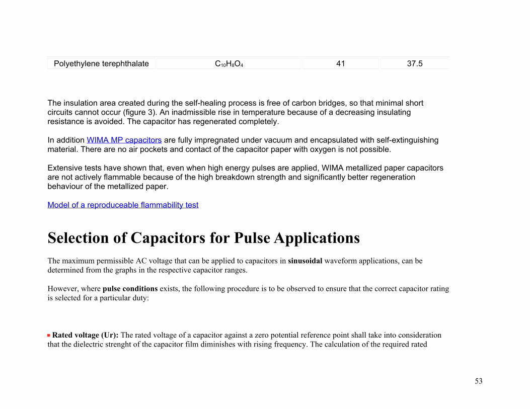
Polyethylene terephthalate C10H8O4 41 37.5
The insulation area created during the self-healing process is free of carbon bridges, so that minimal short circuits cannot occur (figure 3). An inadmissible rise in temperature because of a decreasing insulating resistance is avoided. The capacitor has regenerated completely.
In addition WIMA MP capacitors are fully impregnated under vacuum and encapsulated with self-extinguishing material. There are no air pockets and contact of the capacitor paper with oxygen is not possible.
Extensive tests have shown that, even when high energy pulses are applied, WIMA metallized paper capacitors are not actively flammable because of the high breakdown strength and significantly better regeneration behaviour of the metallized paper.
Model of a reproduceable flammability test
Selection of Capacitors for Pulse ApplicationsThe maximum permissible AC voltage that can be applied to capacitors in sinusoidal waveform applications, can be determined from the graphs in the respective capacitor ranges.
However, where pulse conditions exists, the following procedure is to be observed to ensure that the correct capacitor rating is selected for a particular duty:
Rated voltage (Ur): The rated voltage of a capacitor against a zero potential reference point shall take into consideration that the dielectric strenght of the capacitor film diminishes with rising frequency. The calculation of the required rated
53

voltage of a capacitor must therefore allow for the correction factor k; where k = dielectric strength of the film at the frequency f in % is shown in graph 1.
Graph 1: Dielectric strength of Polypropylene film as a factor of frequency (general guide).
The calculation of the required dielectric strength is shown in the following example(Umin, Umax have the same polarity).
54

Furthermore the rms voltage derived from the peak to peak voltage shall not be greater than the nominal AC voltage rating of the capacitor to avoid the ionization inception level:Urms < UAC rated.
Maximum current: The voltage gradient or rise time of the pulse is taken as the reference point when calculating the maximum current rating of the end contacts. The maximum possible current load on the end contacts is calculated by means of the voltage rise of the pulse (pulse rise time F).Imax = F x C x 1.6
The data of the rated pulse rise time Fr for pulses equal to the rated rated voltage figure in the technical data of the different types. With low voltage rise in operation (Upp) the permissible current load is calculated as follows:
55

for example Ur = 63 V, Upp = 12 V, Fr = 50 V/µsec.
hence Fmax = x 50 = 262.5 V/µsec.
When using maximum current ratings, self-heating must be taken into account at higher frequencies, and must not exceed 8 K.
Dissipation (heat losses): The heat dissipated by a capacitor when stressed by non-sinusoidal voltages or when under pulse conditions can be approximately determined from the following formula:
Pd = Urms2 x C x tan where
Pd = dissipation in Watts (see table 1 for the max.W per K).
Urms = root mean square value of the AC voltage share
= 2 x f, where f is the repetition frequency of the pulse waveform. C = capacitance in Farad
tan = dissipation factor corresponding to the frequency of the steepest part of the pulse.
pulse frequency =
The temperature rise is as follows:
56
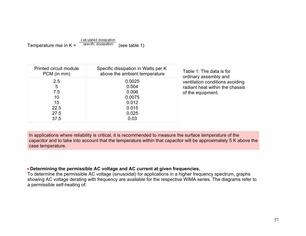
Temperature rise in K = (see table 1)
Printed circuit modulePCM (in mm)
Specific dissipation in Watts per K above the ambient temperature
2.55
7.51015
22.527.537.5
0.00250.0040.0060.00750.0120.0150.0250.03
Table 1: The data is for ordinary assembly and ventilation conditions avoiding radiant heat within the chassis of the equipment.
In applications where reliability is critical, it is recommended to measure the surface temperature of the capacitor and to take into account that the temperature within that capacitor will be approximately 5 K above the case temperature.
Determining the permissible AC voltage and AC current at given frequencies.To determine the permissible AC voltage (sinusoidal) for applications in a higher frequency spectrum, graphs showing AC voltage derating with frequency are available for the respective WIMA series. The diagrams refer to a permissible self-heating of:
57

< 10 K.
For the WIMA MKP 10 / 0.01µF / 630VDC/400VAC, for example, this shows - when f = 50kHz - a permissible AC voltage of
Urms = 280 V (graph 2).
Graph 2: Permissible AC voltage in relation to frequency at 10°C internal temperature rise (general guide).
The AC voltage given in the diagrams can also be used to determine the maximum effective current
58

Xc = 318
Ic = 0.88 A
The calculated maximum value of the effective current
Ip = 1.24 A must not exceed the maximum current rating specified in the maximum pulse rise time calculation (see Fmax above). In this case, the operating AC voltage is to be reduced accordingly.
Selection example for pulse application capacitors
Selection Example for Pulse Application Capacitors
59

Determination of the nominal voltage
Calculation is based on an operating temperature < +60°C unless other data is given by the user.
Ur > 350 VUrms 85 V (referring to AC voltage share)Selected nominal voltage: 400VDC / 250VAC lead spacing 27.5mm
Permissible voltage gradient
The voltage rise time is ~ 87.5 V/µsec.
Value from the table "pulse rise time WIMA FKP 1": 7000 V/µsec.
The calculated voltage gradient is lower than the permissible value shown in the catalogue for this capacitor.
Dissipation
60
Given: Urms
fC
= 85 V= 32 kHz= 0.1 µF
The frequency determined from the steepest part of the pulse is:Pulse width = 15 µsec = 1 cycle.
Hence pulse frequency = ~ 66 kHz
The tan of WIMA FKP 1 at 66 kHz ~ 10 x 10-4 (graph: Dissipation factor change versus frequency)Pd = 852 x 2 x 32 x 103 x 0.1 x 10-6 x 10 x 10-4 ~ 0.145 Watts.
The selected capacitor has a lead spacing of 27.5mm (specific dissipation = 0.025 W/K according to table 1) and the temperature rise due to self-heating is:
Temperature rise = ~ + 6K
The temperature rise plus the max. ambient temperature = max. permissible operating temperature (taking into account the voltage derating in the Electrical Data). If the permissible temperature is exceeded, then select a capacitor with a higher voltage rating.
Alternatively, our engineers will submit their recommendations upon receipt of voltage and current oscillogrammes. Questionnaire available on demand at WIMA Sales Office
61
Overview MKP 10
FKP 4
FKP 1
PDF-File
Page 2
Polypropylene (PP) Capacitors for Pulse Applications with Metal Foil Electrodes, Schoopage Contacts, Double-Sided Metallization and Self-Healing, Internal Series Connection for Highest Current Carrying Capability in PCM 15 mm to 37.5 mm Special Features
Extremely high pulse dutySelf-healingInternal series connectionVery low dissipation factorNegative capacitance change
versus
temperatureAccording to RoHS 2002/95/EC
Typical ApplicationsFor high pulse and high frequency applications e.g.
Switch mode power suppliesConverter in drives and power
electronics
Electrical DataCapacitance range:100 pF to 0.22 µF (E12-values on request)Rated voltages:400VDC, 630VDC, 1000VDC, 1250VDC, 1600VDC, 2000VDC, 4000VDC, 6000VDCCapacitance tolerances:±20%, ±10%, ±5% (other tolerances are available subject to special enquiry)Operating temperature range:-55°C to +100°CClimatic test category:55/100/56 in accordance with IECInsulation resistance at +20°C:
Test voltage: 2 Ur, 2sec / 6 kV: 1.6 Ur, 2secDielectric absorption:0.05%Voltage derating: A voltage derating factor of 1.35% per K must be applied from +85°C for DC voltages and from +75°C for AC voltages.Reliability:Operational life > 300000 hoursFailure rate < 1 fit (0.5 x Ur and 40°C)
Graphs:
62

Deflection systems in monitors
and TV-setsElectronic ballasts
ConstructionDielectric: Polypropylene (PP) filmCapacitor electrodes:Aluminium foil and double-sided metallized plastic filmInternal construction:
Encapsulation: Solvent-resistant, flame-retardent plastic case with epoxy resin seal, UL 94 V-0 Terminations:Tinned wireMarking:Colour: Red. Marking: Black. Epoxy resin seal: Yellow
C < 0.1 µF: > 1 x 10⁵ M(mean value: 5 x 10⁵ M )C > 0.1 µF: > 30000 sec (M xµF)(mean value: 100000 sec)Measuring voltage: 100V/1 min.Dissipation factors at +20°C: tan
Soldering:
at f C < 0.1 µF 0.1 µF < C < 0.22 µF
1kHz 10kHz 100kHz
< 3 x 10⁻⁴
< 4 x 10⁻⁴
< 10 x 10-4
< 3 x 10⁻⁴
< 6 x 10⁻⁴
-
Maximum pulse rise time: for pulses equal to the rated voltageCapacitance
pF/µFmax. pulse rise time V/µsec at TA < 40°C
400VDC
630VDC
1000VDC
1250VDC
1600VDC
2000VDC
4000VDC
6000VDC
100...220330...680
1000...22003300...68000.01 ...0.0220.033...0.068
0.1...0.22
--
290009000900090007000
--
2900014000110001100011000
--
2900027000110001100011000
--
2900029000110001100011000
56000510004600029000110001100011000
560005600051000290001300011000
-
-56000510002900013000
--
-56000510002900013000
--
Mechanical Tests PackingPull test on leads:d < 0.8 Ø: 10 N in direction of leadsd > 0.8 Ø: 20 N in direction of leadsaccording to IEC 60068-2-21Vibration:6 hours at 10...2000Hz and 0.75mm displacement amplitude or 10g in
Available taped and reeled up to and including case size 15x26x31.5 / PCM 27.5mm.
Detailed taping information:
63

accordance with IEC 60068-2-6Low air density:1kPa = 10 mbar in accordance with IEC 60068-2-13Bump test:4000 bumps at 390 m/sec2 in accordance with IEC 60068-2-29
Example for ordering / Part number:
Typical Characteristics and Graphsof the Polypropylene (PP) Film
Polypropylene Film and Foil Types
Metallized Polypropylene Types
64
Typical ApplicationsFor high frequency and high pulseapplications e.g.
Sample and holdTimingLC-FilteringOscillating circuitsAudio equipmentHigh frequency coupling and
decouplingTV and monitor setsLightingPower electronics
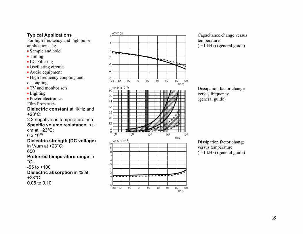
Film PropertiesDielectric constant at 1kHz and +23°C:2.2 negative as temperature riseSpecific volume resistance in cm at +23°C:6 x 10¹⁸
Dielectric strength (DC voltage)in V/µm at +23°C:650Preferred temperature range in °C:-55 to +100Dielectric absorption in % at +23°C:0.05 to 0.10
Capacitance change versus temperature(f=1 kHz) (general guide)
Dissipation factor change versus frequency(general guide)
Dissipation factor change versus temperature(f=1 kHz) (general guide)
65
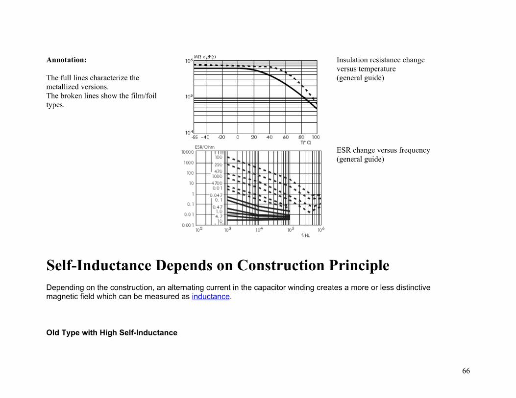
Annotation:
The full lines characterize the metallized versions.The broken lines show the film/foil types.
Insulation resistance change versus temperature(general guide)
ESR change versus frequency(general guide)
Self-Inductance Depends on Construction PrincipleDepending on the construction, an alternating current in the capacitor winding creates a more or less distinctive magnetic field which can be measured as inductance.
Old Type with High Self-Inductance
66

The tape length of the winding element determinesthe value of the self-inductance
Modern WIMA Type
Modern plastic film capacitors are contacted over the whole end surface of the winding element. In this way the self-inductance of the winding element is short-circuited.
The self-inductance is reduced to the PCM (0.8 nH/mm) and the remaining length of the terminating wires (in case of SMD capacitors the distance between the soldering plates).
Average value for practical applications: inductance related to length = 0.8 nH/mmExample: length of the terminating wires = 2 x 3 mm + PCM
67

WIMA MKS 02 / PCM 2.5 mm Self-inductance L < 8 nH
WIMA SMD /Size code 1812Self-inductance L < 6 nH
Increasing winding lengths in relation to the capacitance result in a large bonding area and guarantee low ESR values.
Thus plastic film capacitors stand out because of their HF properties which are the same as or better than those of ceramic capacitors of comparable size.
Comparison of Impedance
68

WIMA MKS 02 / 0.1µF/ PCM 2.5mmZ = f(f) / f(T) -20° to +85°C
(also applicable for size code 1812)
WIMA MKS 2 / 0.1µF/ PCM 5mmZ = f(f) / f(T) -20° to +85°C
(also applicable for size code 2220)
69
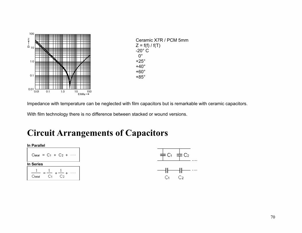
Ceramic X7R / PCM 5mmZ = f(f) / f(T)-20° C..0° +25°+40°+60°+85°
Impedance with temperature can be neglected with film capacitors but is remarkable with ceramic capacitors.
With film technology there is no difference between stacked or wound versions.
Circuit Arrangements of CapacitorsIn Parallel
In Series
70

Marking of WIMA CapacitorsSMD Capacitors
Marking of WIMA SMD capacitors was gradually ceased as of July 2003. Identification is possible by the labelling of packages and delivery notes respectively.
Through-Hole Capacitors
In general, WIMA through-hole capacitors are marked on the front side of the box in plain text with brand name, capacitor series, capacitance, nominal voltage, date code and tolerance. Capacitors with PCM smaller than 15 mm will have the tolerance indicated on the reverse. Standard tolerance 20% is not marked.
PCM 2.5mm and PCM 5mm film/foil
71

PCM 5mm metallized *
PCM 7.5 and 10mm
PCM 15 through 37.5mm
The series name MKS 2, FKP 3 etc. is composed as follows:
The first letter indicates the type of construction
"M" = metallized construction
72
"F" = film/foil construction (brands of other manufacturers are missing this letter)
The second letter "K" stands for plastic film capacitors.
The third letter indicates the dielectric film used
"S" = Polyester / PET (other manufacturers are using "T")
"P" = Polypropylene / PP
The numbers following are WIMA-specific markings.
Metallized paper capacitors are marked with "MP".
The cases of 2.5 mm and 5 mm capacitors are too small to imprint with the series type (i.e. MKS 2, FKS 2 etc.). Instead, these capacitors must be identified by different colours of the marking inks and epoxy fill.
73

PCM 2.5 mm
Case Marking Example Notice
FKP 02 Red Black Yellow epoxy fill
MKS 02 Red Silver Yellow epoxy fill
PCM 5 mm Case Marking Example Notice
FKS 2 Red Silver Yellow epoxy fill
FKP 2 Red Black Yellow epoxy fill
MKS 2 Red Silver/White* Red epoxy fill
MKP 2 Red Black* Red epoxy fill
* As of September 2005 WIMA changes step by step the metallized capacitors in PCM 5 mm to top marking. Following series are concerned:
WIMA MKS 2:(Marking White)
WIMA MKP 2: (Marking Black)
74

Application Guide for WIMA Capacitors PDF
OverviewFields of Application
Automotive Power Lighting Medical Consumer Telecom/DataNew Energy
Product Family Range Description Picture
SMD Capacitors
Size Codes 1812 - 6054
SMD-PET/-PPS
Film Capacitors
PCM 2.5 - 37.5 mm
MKS, MKP,
FKS, FKP
Pulse Duty Capacitors PCM 7.5 - 37.5 mm
75

MKP 10, FKP 4, FKP 1
EMI Suppression Capacitors
PCM 7.5 - 27.5 mm
MKP-X2/-Y2
MP 3-X2/-X1/-Y2/R-Y2
Snubber Capacitors
Variable terminations
Snubber MKP/FKP
GTO Capacitors
Axial screw connection
GTO MKP
76
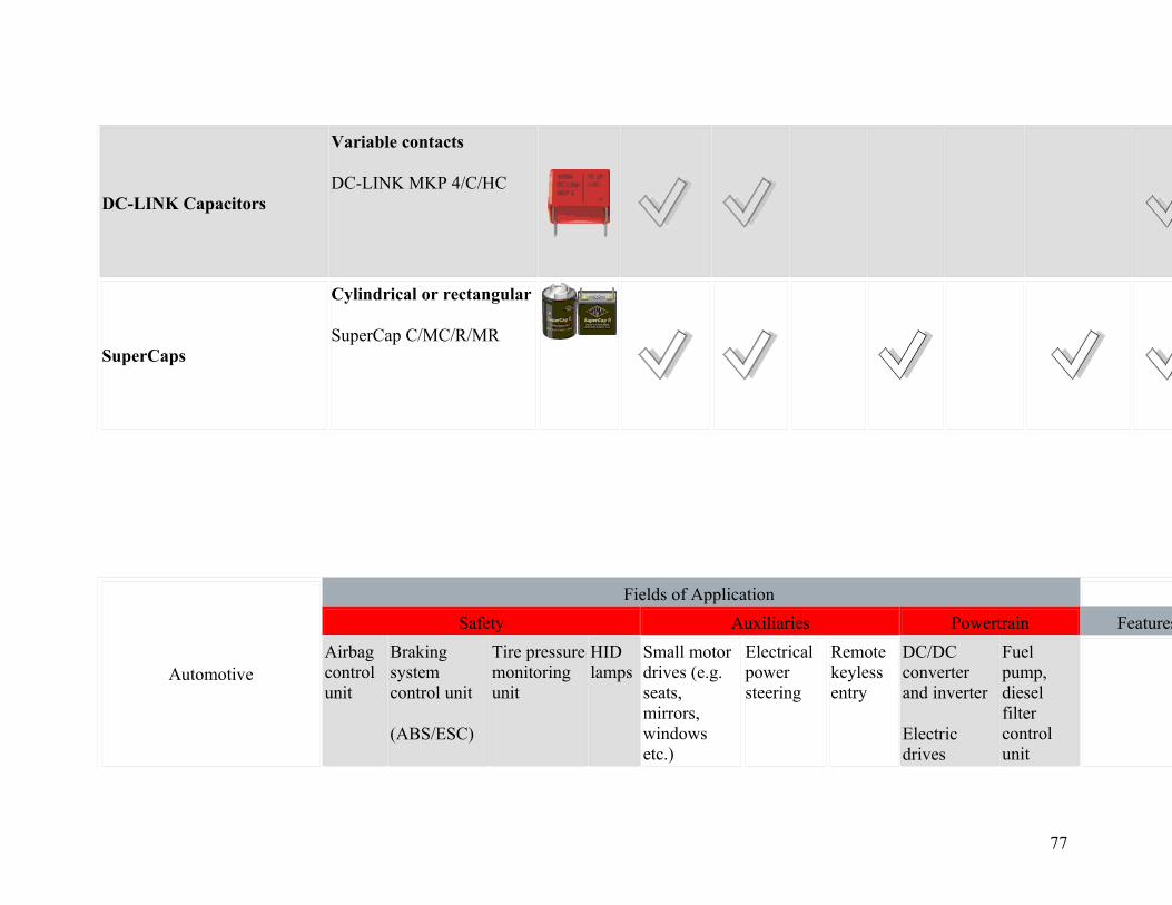
DC-LINK Capacitors
Variable contacts
DC-LINK MKP 4/C/HC
SuperCaps
Cylindrical or rectangular
SuperCap C/MC/R/MR
Automotive
Fields of Application
Safety Auxiliaries Powertrain Features
Airbag control unit
Braking system control unit
(ABS/ESC)
Tire pressure monitoring unit
HID lamps
Small motor drives (e.g. seats, mirrors, windows etc.)
Electrical power steering
Remote keyless entry
DC/DC converter and inverter
Electric drives
Fuel pump, diesel filter control unit
77

SMD Capacitors
0.01 µF - 6.8 µF
63 - 1000 VDC
Size 1812 - 6054
SMD-PPS
SMD-PPS SMD-PET,
SMD-PPS
SMD-PET SMD-PET SMD-PET
SMD-PET Operating temp. up to 140°COperating life > 300.000 hSuitable for lead-free
soldering at T < 250°C
Film Capacitors
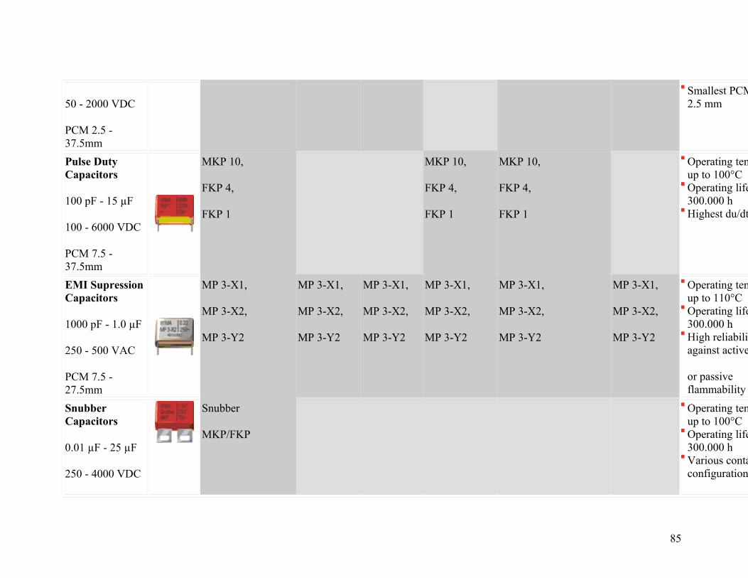
1000 pF - 220 µF
50 - 2000 VDC
PCM 2.5 - 37.5mm
MKS,
FKS
MKS,
FKS
MKP MKS,
MKP,
FKS
MKP MKS Operating temp. up to 100°COperating life > 300.000 hSmallest PCM 2.5mm
Pulse Duty Capacitors
100 pF - 15 µF
100 - 6000 VDC
PCM 7.5 - 37.5mm
MKP 10,
FKP 4,
FKP 1,
MKP
MKP 10,
FKP 4,
FKP 1,
MKP
Operating temp. up to 100°COperating life > 300.000 hHighest du/dt
78

Snubber Capacitors
0.01 µF - 25 µF
250 - 4000 VDC
Variable terminations
Snubber
MKP/FKP
Operating temp. up to 100°COperating life > 300.000 hVarious contact
configurations
DC-LINK Capacitors
5 µF - 4500 µF
400 - 1600 VDC
Variable terminations
DC-LINK Operating temp. up to 100°COperating life > 200.000 h4-lead or screwable plate
connections
SuperCaps
12 F - 840 F
5 - 112 VDC
(+customized)
SuperCap MC/MR modules for boardnet stabilisation and safety back-up
SuperCap MC/MR modules for local power supply
SuperCap MC/MR modules for recuperation of braking energy/power boost
Operating temp. -30/+65°COperating life > 10 yearsDischarge current up to
several 1000 A
79

Power Electronics
Fields of Application
Power Electronics Features
Battery charger Frequency converter
Power supply / SMPS
UPS Electronic power meter
SMD Capacitors
0.01 µF - 6.8 µF
63 - 1000 VDC
Size 1812 - 6054
SMD-PET SMD-PET,
SMD-PPS
Operating temp. up to 140°COperating life > 300.000 hSuitable for lead-free
soldering at T < 250°C
Film Capacitors
1000 pF - 220 µF
50 - 2000 VDC
PCM 2.5 - 37.5mm
MKS, MKP, FKS
MKS, MKP,FKS
Operating temp. up to 100°COperating life > 300.000 hSmallest PCM 2.5 mm
Pulse Duty Capacitors
100 pF - 15 µF
MKP 10,
FKP 4,
MKP 10,
FKP 4,
Operating temp. up to 100°COperating life > 300.000 h
80

100 - 6000 VDC
PCM 7.5 - 37.5mm
FKP 1,
MKP
FKP 1,
MKP
Highest du/dt
EMI Supression Capacitors
1000 pF - 2.2 µF
250 - 500 VAC
PCM 7.5 - 27.5mm
MP 3-X1/-X2/-Y2
MKP-X2/-Y2
MP 3-X1/-X2/-Y2
MKP-X2/-Y2
MP 3-X1/-X2/-Y2
MKP-X2/-Y2
Operating temp. up to 110°COperating life > 300.000 hHigh reliability against active
or passive flammability (MP)
Snubber Capacitors
0.01 µF - 25 µF
250 - 4000 VDC
Variable terminations
Snubber
MKP/FKP
Snubber
MKP/FKP
Snubber
MKP/FKP
Operating temp. up to 100°COperating life > 300.000 hVarious contact configurations
DC-LINK Capacitors
5 µF - 4500 µF
400 - 1600 VDC
Variable terminations
DC-LINK Operating temp. up to 100°COperating life > 200.000 h4-lead and screwable plate
configurations
81
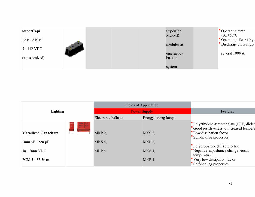
SuperCaps
12 F - 840 F
5 - 112 VDC
(+customized)
SuperCap MC/MR
modules as
emergency backup
system
Operating temp. -30/+65°COperating life > 10 yearsDischarge current up to
several 1000 A
Lighting
Fields of Application
Power Supply Features
Electronic ballasts Energy saving lamps
Metallized Capacitors
1000 pF - 220 µF
50 - 2000 VDC
PCM 5 - 37.5mm
MKP 2,
MKS 4,
MKP 4
MKS 2,
MKP 2,
MKS 4,
MKP 4
Polyethylene-terephthalate (PET) dielectric Good resistiveness to increased temperature Low dissipation factor Self-healing properties
Polypropylene (PP) dielectric Negative capacitance change versus temperature Very low dissipation factor Self-healing properties
82
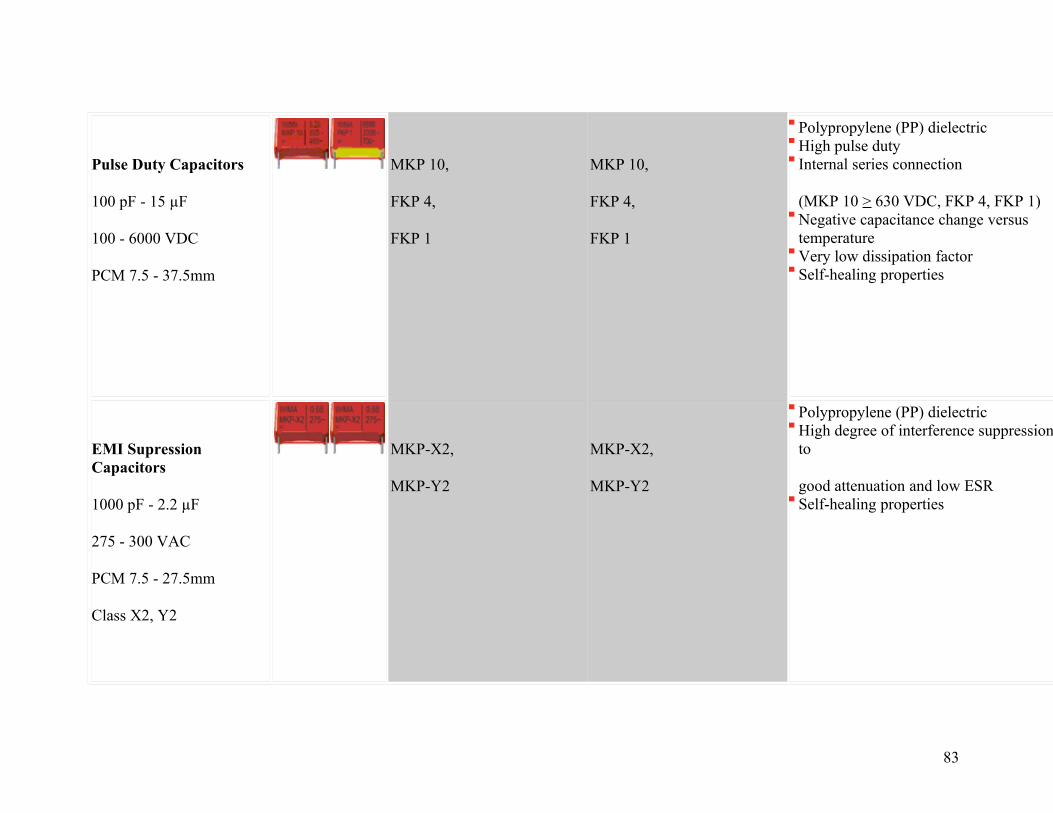
Pulse Duty Capacitors
100 pF - 15 µF
100 - 6000 VDC
PCM 7.5 - 37.5mm
MKP 10,
FKP 4,
FKP 1
MKP 10,
FKP 4,
FKP 1
Polypropylene (PP) dielectricHigh pulse duty Internal series connection
(MKP 10 > 630 VDC, FKP 4, FKP 1) Negative capacitance change versus temperatureVery low dissipation factorSelf-healing properties
EMI Supression Capacitors
1000 pF - 2.2 µF
275 - 300 VAC
PCM 7.5 - 27.5mm
Class X2, Y2
MKP-X2,
MKP-Y2
MKP-X2,
MKP-Y2
Polypropylene (PP) dielectricHigh degree of interference suppression due to
good attenuation and low ESR Self-healing properties
83

Medical
Fields of Application
Medical Equipment Features
Imaging equipment (CT, MRT, X-Ray, ultrasound)
Anesthesia equipment
Cleaning equipment
Defibrillation devices
Patient care monitoring (glucose meter, blood gas analyser, telemetry)
Respiration technology
SMD Capacitors
0.01 µF - 6.8 µF
63 - 1000 VDC
Size 1812 - 6054
SMD-PET,
SMD-PPS
SMD-PET,
SMD-PPS
SMD-PET,
SMD-PPS
SMD-PET,
SMD-PPS
Operating temp. up to 140°COperating life > 300.000 hSuitable for lead-free
soldering at T 250°C
Film Capacitors
1000 pF - 220 µF
MKP MKS,
MKP
MKS,
MKP
MKS,
MKP
MKS,
MKP
Operating temp. up to 100°COperating life > 300.000 h
84
50 - 2000 VDC
PCM 2.5 - 37.5mm
Smallest PCM 2.5 mm
Pulse Duty Capacitors
100 pF - 15 µF
100 - 6000 VDC
PCM 7.5 - 37.5mm
MKP 10,
FKP 4,
FKP 1
MKP 10,
FKP 4,
FKP 1
MKP 10,
FKP 4,
FKP 1
Operating temp. up to 100°COperating life > 300.000 hHighest du/dt
EMI Supression Capacitors
1000 pF - 1.0 µF
250 - 500 VAC
PCM 7.5 - 27.5mm
MP 3-X1,
MP 3-X2,
MP 3-Y2
MP 3-X1,
MP 3-X2,
MP 3-Y2
MP 3-X1,
MP 3-X2,
MP 3-Y2
MP 3-X1,
MP 3-X2,
MP 3-Y2
MP 3-X1,
MP 3-X2,
MP 3-Y2
MP 3-X1,
MP 3-X2,
MP 3-Y2
Operating temp. up to 110°COperating life > 300.000 hHigh reliability against active
or passive flammability
Snubber Capacitors
0.01 µF - 25 µF
250 - 4000 VDC
Snubber
MKP/FKP
Operating temp. up to 100°COperating life > 300.000 hVarious contact configurations
85

Variable terminations
SuperCaps
100 F - 6500 F
2.5 VDC
(+customized)
SuperCap C/R Operating temp. -30/+65°COperating life > 10 yearsDischarge current up to
several 1000 A
Consumer
Fields of Application
Consumer Electronics Features
High-end audio systems
Amplifier LCD / Plasma TVs
Set top boxes
Video systems
Control units for home appliances
White goods (induction cooker, ignition units etc.)
SMD Capacitors
0.01 µF - 6.8 µF
63 - 1000 VDC
SMD-PPS SMD-PET,
SMD-PPS
SMD-PET SMD-PET Operating temp. up to 140°COperating life > 300.000 hSuitable for lead-
86

Size 1812 - 6054 free
soldering at T < 250°C
Film Capacitors
27 pF - 220 µF
50 - 2000 VDC
PCM 2.5 - 37.5mm
MKS,
MKP,
FKP
MKS,
MKP,
FKP
MKP MKS MKS,
MKP
MKS,
MKP,
FKS
Operating temp. up to 100°COperating life > 300.000 hSmallest PCM 2.5 mm
Pulse Duty Capacitors
100 pF - 15 µF
100 - 6000 VDC
PCM 7.5 - 37.5mm
MKP 10 MKP 10 MKP 10 MKP 10,
FKP 4,
FKP 1
MKP 10,
FKP 4,
FKP 1
Operating temp. up to 100°COperating life > 300.000 hHighest du/dt
EMI Supression Capacitors
1000 pF - 2.2 µF
250 - 500 VAC
PCM 7.5 - 27.5mm
MP 3-X1/-X2/-Y2,
MKP-X2/-Y2
MP 3-X1/-X2/-Y2,
MKP-X2/-Y2
MKP-X2,
MKP-Y2
MKP-X2,
MKP-Y2
MKP-X2,
MKP-Y2
MP 3-X1/-X2/-Y2,
MKP-X2/-Y2
Operating temp. up to 110°COperating life > 300.000 hHigh reliability against active
or passive flammability (MP)
87

Snubber Capacitors
0.01 µF - 25 µF
250 - 4000 VDC
Variable terminations
Snubber
MKP/FKP
Operating temp. up to 100°COperating life > 300.000 hVarious contact configurations
Telecom / Data
Fields of Application
Telecommunication / Data Processing Features
Power supply
Splitter Data processing systems (server etc.)
Network devices (router, switcher, hubs, modems)
Wireless communication (WLAN, UMTS etc.)
Memory backup
SMD Capacitors
0.01 µF - 6.8 µF
63 - 1000 VDC
Size 1812 - 6054
SMD-PET,
SMD-PPS
SMD-PET,
SMD-PPS
SMD-PET,
SMD-PPS
SMD-PET,
SMD-PPS
Operating temp. up to 140°COperating life > 300.000 hSuitable for lead-free
soldering at T
88
250°C
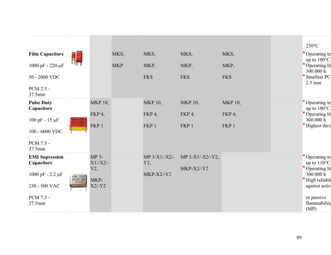
Film Capacitors
1000 pF - 220 µF
50 - 2000 VDC
PCM 2.5 - 37.5mm
MKS,
MKP
MKS,
MKP,
FKS
MKS,
MKP,
FKS
MKS,
MKP,
FKS
Operating temp. up to 100°COperating life > 300.000 hSmallest PCM 2.5 mm
Pulse Duty Capacitors
100 pF - 15 µF
100 - 6000 VDC
PCM 7.5 - 37.5mm
MKP 10,
FKP 4,
FKP 1
MKP 10,
FKP 4,
FKP 1
MKP 10,
FKP 4,
FKP 1
MKP 10,
FKP 4,
FKP 1
Operating temp. up to 100°COperating life > 300.000 hHighest du/dt
EMI Supression Capacitors
1000 pF - 2.2 µF
250 - 500 VAC
PCM 7.5 - 27.5mm
MP 3-X1/-X2/-Y2,
MKP-X2/-Y2
MP 3-X1/-X2/-Y2,
MKP-X2/-Y2
MP 3-X1/-X2/-Y2,
MKP-X2/-Y2
Operating temp. up to 110°COperating life > 300.000 hHigh reliability against active
or passive flammability (MP)
89

SuperCaps
100 F - 6500 F
2.5 VDC
(+customized)
SuperCap C/R Operating temp. -30/+65°COperating life > 10 yearsDischarge current up to
several 1000 A
New Energy
Fields of Application
New Energy Features
Energy storage in photovoltaic systems
Converter Power supply UPS
Pulse Duty Capacitors
100 pF - 15 µF
100 - 6000 VDC
PCM 7.5 -
MKP 10,
FKP 4,
FKP 1,
MKP
MKP 10,
FKP 4,
FKP 1,
MKP
MKP 10,
FKP 4,
FKP 1,
MKP
Operating temp. up to 100°COperating life > 300.000 hHighest du/dt
90

37.5mm
Snubber Capacitors
0.01 µF - 25 µF
250 - 4000 VDC
Variable terminations
Snubber
MKP/FKP
Snubber
MKP/FKP
Snubber
MKP/FKP
Operating temp. up to 100°COperating life > 300.000 hVarious contact configurations
GTO Capacitors
1µF - 100 µF
400 - 1600 VDC
Axial screw connection
GTO MKP GTO MKP GTO MKP Operating temp. up to 85 °COperating life > 300.000 hAxial screw and thread connections
DC-LINK Capacitors
5 µF - 4500 µF
400 - 1600
DC-LINK DC-LINK DC-LINK Operating temp. up to 100°COperating life > 200.000 h4-lead or screwable
91
VDC
Variable terminations
plate
connections
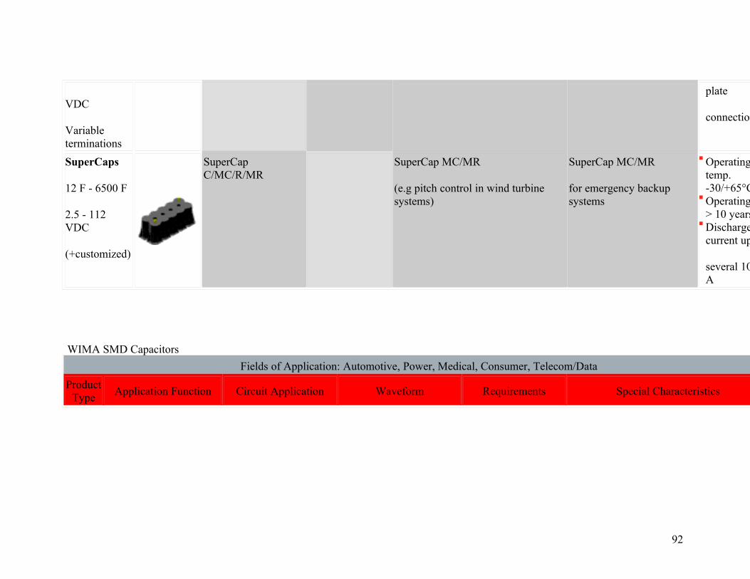
SuperCaps
12 F - 6500 F
2.5 - 112 VDC
(+customized)
SuperCap C/MC/R/MR
SuperCap MC/MR
(e.g pitch control in wind turbine systems)
SuperCap MC/MR
for emergency backup systems
Operating temp. -30/+65°COperating life > 10 yearsDischarge current up to
several 1000 A
WIMA SMD Capacitors
Fields of Application: Automotive, Power, Medical, Consumer, Telecom/Data
Product Type
Application Function Circuit Application Waveform Requirements Special Characteristics
92

SMD-PET
SMD-PPS
Blocking/Coupling
High-Pass Filter:
-preventing DC voltages-transferring AC voltages
-High insulation resistance
-Low self-inductance (to observe voltage rating)
Operating temperatures up to 100°C (SMD-PET) and 140°C (SMD-PPS) Suitable for lead-free soldering at elevated processing temperature Tpeak = 250°C (SMD-PPS) Suitable for filtering due to low dissipation factor (SMD-PPS)
Compared to Ceramic SMD (MLCC):
No internal cracks or delamination C/C over temperature: very low (SMD-
PET) or extremely low (SMD-PPS) Self-healing capability -> high withstanding voltage, high reliability
Bypass/Decoupling
Low-Pass Filter:
-suppressing transmission of high frequencies (AC voltages)
-High insulation resistance
-Low self-inductance
Smoothing
-smoothing of pulsating DC-voltages from AC-rectifier
-Comparably high capacitance
-Low dissipation factor (to observe frequency)
SMD-PPS
Band-Pass Filter (e.g. Audio, TV)
-pass frequencies within a certain range
-attenuate frequencies outside that range
-Low dissipation factor
-Stable capacitance
93
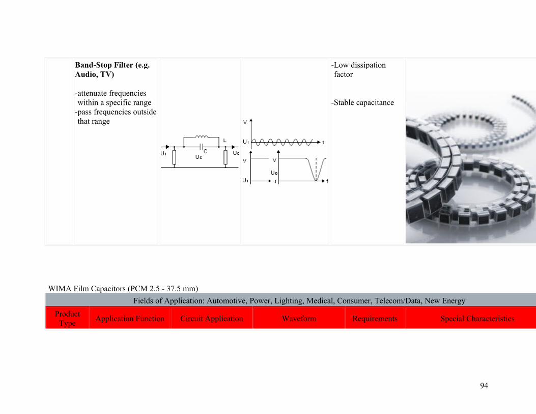
Band-Stop Filter (e.g. Audio, TV)
-attenuate frequencies within a specific range
-pass frequencies outside that range
-Low dissipation factor
-Stable capacitance
WIMA Film Capacitors (PCM 2.5 - 37.5 mm)
Fields of Application: Automotive, Power, Lighting, Medical, Consumer, Telecom/Data, New Energy
Product Type
Application Function Circuit Application Waveform Requirements Special Characteristics
94
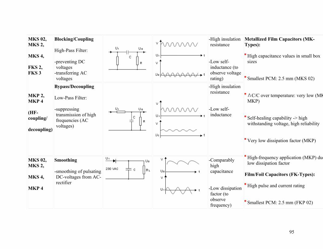
MKS 02, MKS 2,
MKS 4,
FKS 2, FKS 3
MKP 2, MKP 4
(HF-coupling/
decoupling)
Blocking/Coupling
High-Pass Filter:
-preventing DC voltages
-transferring AC voltages
-High insulation resistance
-Low self-inductance (to observe voltage rating)
Metallized Film Capacitors (MK-Types):
High capacitance values in small box sizes
Smallest PCM: 2.5 mm (MKS 02)
C/C over temperature: very low (MKS,
MKP)
Self-healing capability -> high withstanding voltage, high reliability
Very low dissipation factor (MKP)
High-frequency application (MKP) due to low dissipation factor
Film/Foil Capacitors (FK-Types):
High pulse and current rating
Smallest PCM: 2.5 mm (FKP 02)
Bypass/Decoupling
Low-Pass Filter:
-suppressing transmission of high frequencies (AC voltages)
-High insulation resistance
-Low self-inductance
MKS 02, MKS 2,
MKS 4,
MKP 4
Smoothing
-smoothing of pulsating DC-voltages from AC-rectifier
-Comparably high capacitance
-Low dissipation factor (to observe frequency)
95

C/C over temperature: very low (FKS,
FKP)
High insulation resistance (FKS) or very high insulation resistance (FKP)
Close tolerances up to 1% (FKP)
High-frequency application (FKP) due to very low dissipation factor
High reliability
FKP 02, FKP 2,
FKP 3,
MKP 2, MKP 4
Band-Pass Filter (e.g. Audio, TV)
-pass frequencies within a certain range
-attenuate frequencies outside that range
-Low dissipation factor
-Stable capacitance
Band-Stop Filter (e.g. Audio, TV)
-attenuate frequencies within a specific range
-pass frequencies outside that range
-Low dissipation factor
-Stable capacitance
FKP 02, FKP 2,
FKP 3,
MKP 2, MKP 4
Timing (e.g. Signal Light)
-when capacitor is charged voltage is increasing over time
-after passing certain value a new state change occurs
-High insulation resistance
-Stable capacitance
FKP 02, FKP 2,
FKP 3,
MKP 2, MKP 4
Sample and Hold (e.g. Amplifier)
Analogue-Digital Converter:
-capacitor is used to
-Low dielectric absorption
-High insulation resistance
96
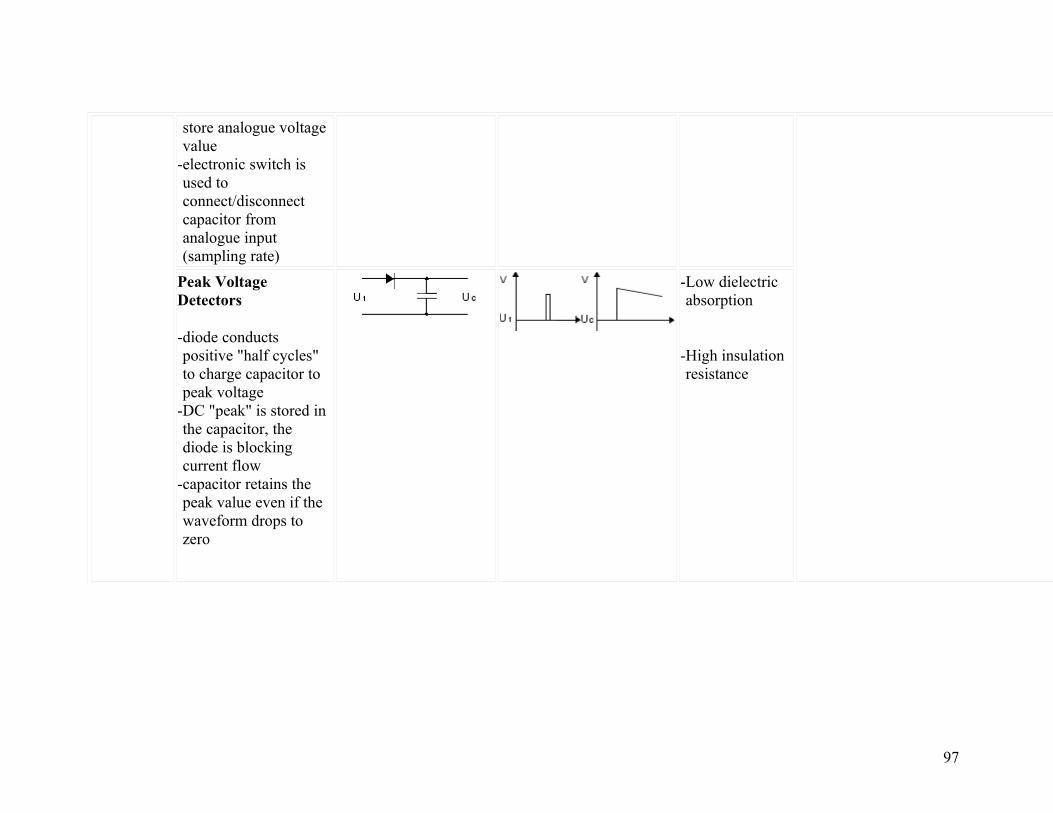
store analogue voltage value
-electronic switch is used to connect/disconnect capacitor from analogue input (sampling rate)
Peak Voltage Detectors
-diode conducts positive "half cycles" to charge capacitor to peak voltage
-DC "peak" is stored in the capacitor, the diode is blocking current flow
-capacitor retains the peak value even if the waveform drops to zero
-Low dielectric absorption
-High insulation resistance
97

WIMA Pulse Duty Capacitors (PCM 7.5 - 37.5 mm)
Fields of Application: Automotive, Power, Lighting, Medical, Consumer, Telecom/Data, New Energy
Product Type
Application Function Circuit Application Waveform Requirements Special Characteristics
MKP 10,
Fly-Back (e.g. Monitor, TV)
-current flows from
-Low dissipation factor
-High pulse rise time
Pulse and current rating: high (MKP 10), very high (FKP 4) or extremely high (FKP 1)
98
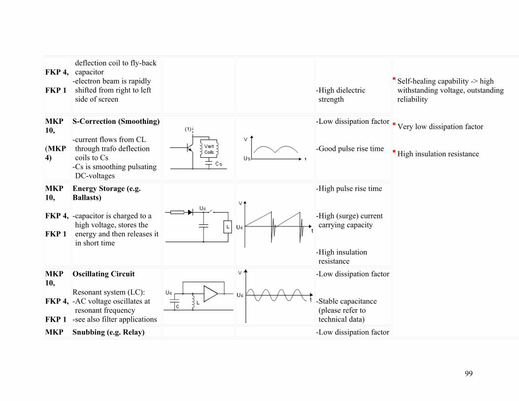
FKP 4,
FKP 1
deflection coil to fly-back capacitor
-electron beam is rapidly shifted from right to left side of screen
-High dielectric strength
Self-healing capability -> high withstanding voltage, outstanding reliability
Very low dissipation factor
High insulation resistance
MKP 10,
(MKP 4)
S-Correction (Smoothing)
-current flows from CL through trafo deflection coils to Cs
-Cs is smoothing pulsating DC-voltages
-Low dissipation factor
-Good pulse rise time
MKP 10,
FKP 4,
FKP 1
Energy Storage (e.g. Ballasts)
-capacitor is charged to a high voltage, stores the energy and then releases it in short time
-High pulse rise time
-High (surge) current carrying capacity
-High insulation resistance
MKP 10,
FKP 4,
FKP 1
Oscillating Circuit
Resonant system (LC): -AC voltage oscillates at resonant frequency
-see also filter applications
-Low dissipation factor
-Stable capacitance (please refer to technical data)
MKP Snubbing (e.g. Relay) -Low dissipation factor
99
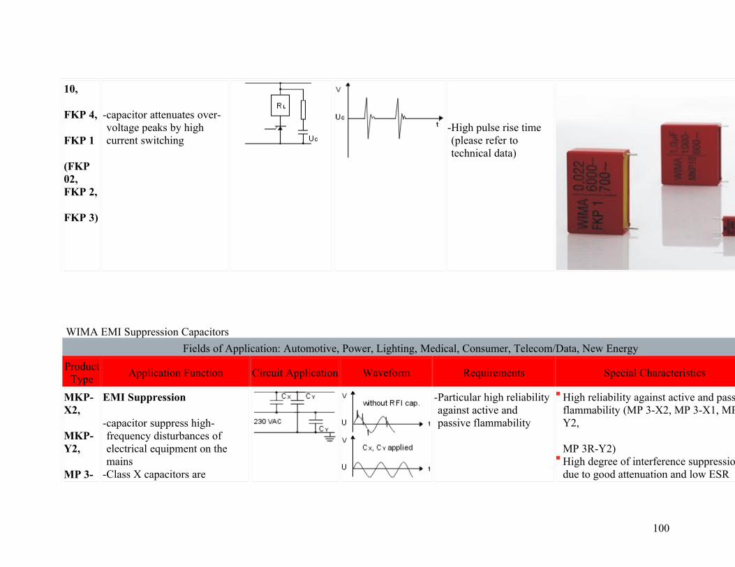
10,
FKP 4,
FKP 1
(FKP 02, FKP 2,
FKP 3)
-capacitor attenuates over-voltage peaks by high current switching
-High pulse rise time (please refer to technical data)
WIMA EMI Suppression Capacitors
Fields of Application: Automotive, Power, Lighting, Medical, Consumer, Telecom/Data, New Energy
Product Type
Application Function Circuit Application Waveform Requirements Special Characteristics
MKP-X2,
MKP-Y2,
MP 3-
EMI Suppression
-capacitor suppress high-frequency disturbances of electrical equipment on the mains
-Class X capacitors are
-Particular high reliability against active and passive flammability
High reliability against active and passive flammability (MP 3-X2, MP 3-X1, MP 3-Y2,
MP 3R-Y2) High degree of interference suppression due to good attenuation and low ESR
100

X2,
MP 3-X1,
MP 3-Y2,
MP 3R-Y2
connected between phase and neutral or phase and phase conductors
-Class Y capacitors are connected between phase conductors and earthed casing and thus by-pass operating insulation
High volume/capacitance ratio (MKP-X2,
MKP-X2 R, MKP-Y2)
MKP-X2,
MKP-X2 R,
(MP 3-X1),
(MKS 4)
(> 630 VDC,
> PCM 10)
Voltage Dropper
-capacitor voltage divider
-High capacitance stability
-Flame retardant (please check if approvals are required)
101

WIMA Snubber Capacitors
Fields of Application: Power, Medical, Consumer, New Energy
Product Type
Application Function Circuit Application Waveform Requirements Special Characteristics
Snubber MKP,
Snubber FKP
Energy Storage
-capacitor is charged to a high voltage, stores the energy and releases it in short time
-High pulse rise time
-High (surge) current carrying capacity
-High insulation resistance
Pulse and current rating: high (Snubber MKP) or very high (Snubber FKP) High volume/capacitance ratio (Snubber MKP) Self-healing capability -> high withstanding voltage, outstanding reliability Very low dissipation factor High insulation resistance Low self-inductance Particularly reliable contact configurations: 4-lead versions or screwable plate connections
Snubber MKP,
Snubber FKP
Snubbing (e.g. IGBT)
-capacitor attenuates over-voltage peaks by high current switching
-Low dissipation factor
-High pulse rise time (please refer to technical data)
-Low self-inductivity
102
WIMA GTO Capacitors
Fields of Application: Power, New Energy
Product Type
Application Function Circuit Application Waveform Requirements Special Characteristics
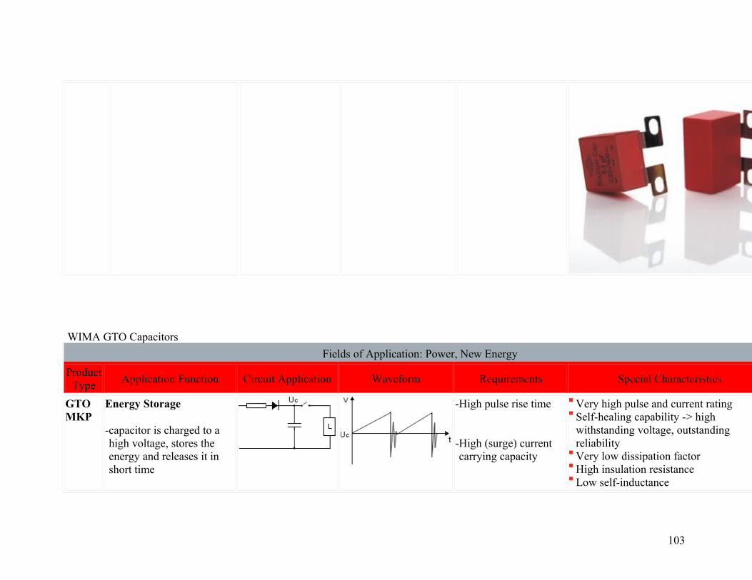
GTO MKP
Energy Storage
-capacitor is charged to a high voltage, stores the energy and releases it in short time
-High pulse rise time
-High (surge) current carrying capacity
Very high pulse and current ratingSelf-healing capability -> high withstanding voltage, outstanding reliability Very low dissipation factor High insulation resistance Low self-inductance
103
-High insulation resistance
High mechanical stability High shock and vibration resistance
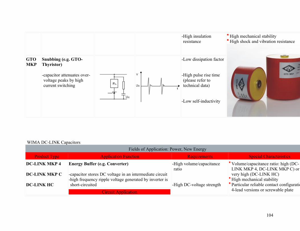
GTO MKP
Snubbing (e.g. GTO-Thyristor)
-capacitor attenuates over-voltage peaks by high current switching
-Low dissipation factor
-High pulse rise time (please refer to technical data)
-Low self-inductivity
WIMA DC-LINK Capacitors
Fields of Application: Power, New Energy
Product Type Application Function Requirements Special Characteristics
DC-LINK MKP 4
DC-LINK MKP C
DC-LINK HC
Energy Buffer (e.g. Converter)
-capacitor stores DC voltage in an intermediate circuit -high frequency ripple voltage generated by inverter is short-circuited
-High volume/capacitance ratio
-High DC-voltage strength
Volume/capacitance ratio: high (DC-LINK MKP 4, DC-LINK MKP C) or very high (DC-LINK HC) High mechanical stability Particular reliable contact configurations: 4-lead versions or screwable plate Circuit Application
104

-Low dissipation factor
connections Advantages Compared to Aluminium Electrolytic Capacitors:
Low self-inductance High ripple current capability High voltage/over-voltage strength by specific metallization (> 450 VDC) due to self-healing capability Very constanc C/C Very low ESR and dissipation factor Dry construction without electrolyte -> high reliability Non polar construction High insulation resistance
WIMA SuperCaps - Automotive
105
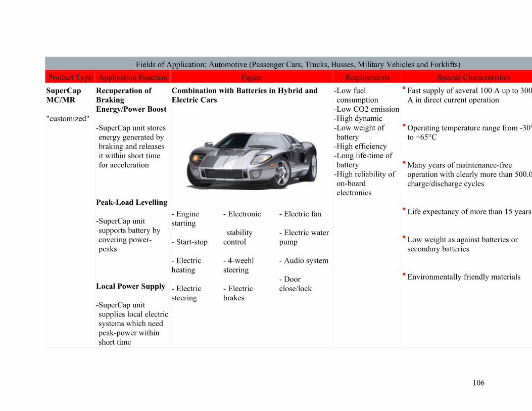
Fields of Application: Automotive (Passenger Cars, Trucks, Busses, Military Vehicles and Forklifts)
Product Type Application Function Figure Requirements Special Characteristics
SuperCap MC/MR
"customized"
Recuperation of Braking Energy/Power Boost
-SuperCap unit stores energy generated by braking and releases it within short time for acceleration
Peak-Load Levelling
-SuperCap unit supports battery by covering power-peaks
Local Power Supply
-SuperCap unit supplies local electric systems which need peak-power within short time
Combination with Batteries in Hybrid and Electric Cars
- Engine starting
- Start-stop
- Electric heating
- Electric steering
- Electronic
stability control
- 4-weehl steering
- Electric brakes
- Electric fan
- Electric water pump
- Audio system
- Door close/lock
-Low fuel consumption
-Low CO2 emission -High dynamic -Low weight of battery
-High efficiency -Long life-time of battery
-High reliability of on-board electronics
Fast supply of several 100 A up to 3000 A in direct current operation
Operating temperature range from -30°C to +65°C
Many years of maintenance-free operation with clearly more than 500.000 charge/discharge cycles
Life expectancy of more than 15 years
Low weight as against batteries or secondary batteries
Environmentally friendly materials
106

Boardnet Stabilisation
-Safety backup for security relevant on-board electronic systems
SuperCap MC/MR
MC 110/14,
MC 200/14,
"customized"
Cranking of Engines
-SuperCap unit supplies peak-power within a short time to crank an engine
-After cranking the engine the SuperCap unit gets charged immediately
Replacement of Starter Batteries
-Power supply under extreme weather conditions (-30°C)
-Long de-energized periods (vintage cars)
-Low maintenance cost
WIMA SuperCaps - Transportation
Fields of Application: Transportation (Tram, Subway, Train)
Product Type Application Function Figure Requirements Special Characteristics
107
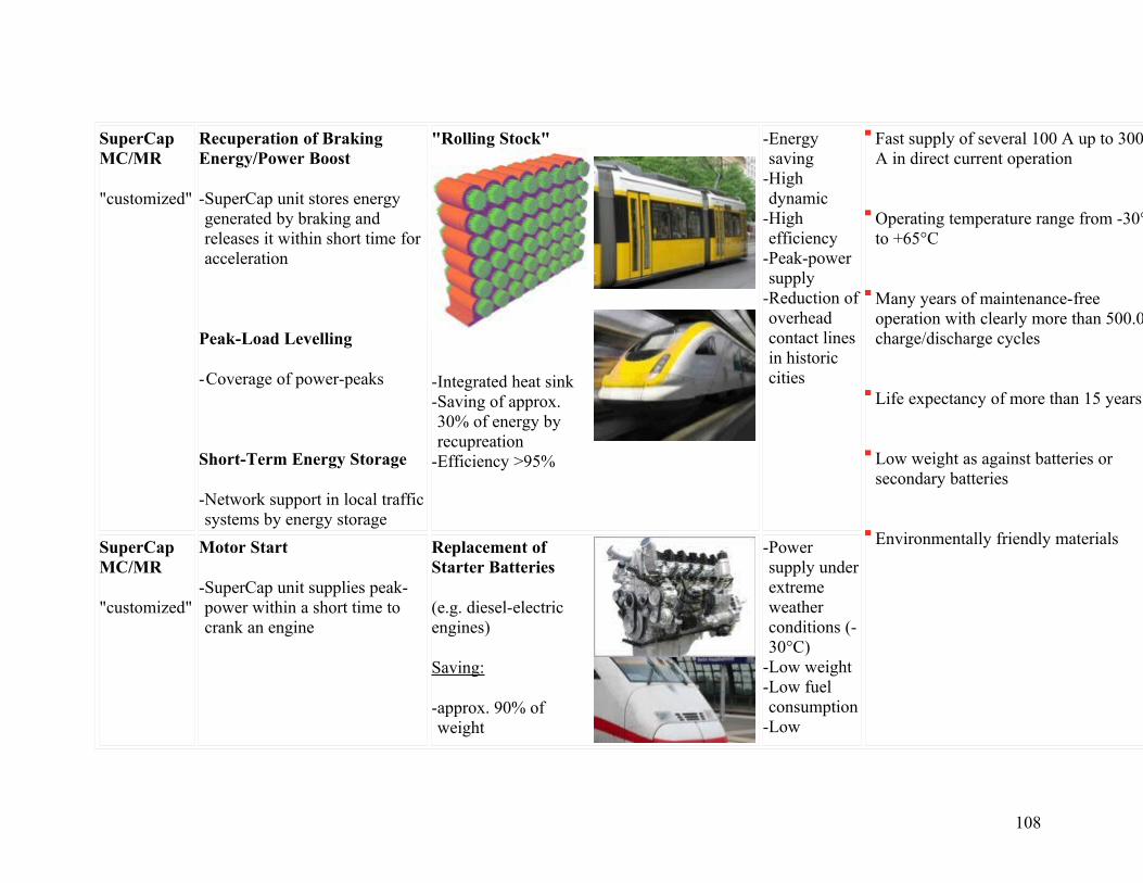
SuperCap MC/MR
"customized"
Recuperation of Braking Energy/Power Boost
-SuperCap unit stores energy generated by braking and releases it within short time for acceleration
Peak-Load Levelling
-Coverage of power-peaks
Short-Term Energy Storage
-Network support in local traffic systems by energy storage
"Rolling Stock"
-Integrated heat sink -Saving of approx. 30% of energy by recupreation
-Efficiency >95%
-Energy saving
-High dynamic
-High efficiency
-Peak-power supply
-Reduction of overhead contact lines in historic cities
Fast supply of several 100 A up to 3000 A in direct current operation
Operating temperature range from -30°C to +65°C
Many years of maintenance-free operation with clearly more than 500.000 charge/discharge cycles
Life expectancy of more than 15 years
Low weight as against batteries or secondary batteries
Environmentally friendly materials
SuperCap MC/MR
"customized"
Motor Start
-SuperCap unit supplies peak-power within a short time to crank an engine
Replacement of Starter Batteries
(e.g. diesel-electric engines)
Saving:
-approx. 90% of weight
-Power supply under extreme weather conditions (-30°C)
-Low weight -Low fuel consumption
-Low
108

-approx. 25% of fuel maintenance cost
WIMA SuperCaps - Power Supply (UPS); Telecom/Data
Fields of Application: Power Supply (UPS); Telecom/Data (Memory Backup)
Product Type Application Function Figure Requirements Special Characteristics
SuperCap MC/MR
"customized"
UPS
-Short-term power supply when mains power failure
UPS-Emergency Backup in Hospitals, Telecommunication Systems, Oil and Gas Extraction
(cost-intensive processes)
-Emergency backup to avoid downtime after short blackout
-Peak-power supply -Long life-time-Low maintenance cost
Fast supply of several 100 A up to 3000 A in direct current operation
Operating temperature range from -30°C
109

Peak-Load Levelling
-Coverage of power-peaks
- Micro-turbine start bridging
to +65°C
Many years of maintenance-free operation with clearly more than 500.000 charge/discharge cycles
Life expectancy of more than 15 years
Low weight as against batteries or secondary batteries
Environmentally friendly materials
SuperCap C/R
Short-Term Energy Storage
-SuperCap unit stores energy for a short time e.g. after voltage drop
Memory Backup - On-Board Logic
-Tr
-Memory backup for seconds/minutes
-Low weight -Low maintenance cost
110

ansferring data from DDR memory
111
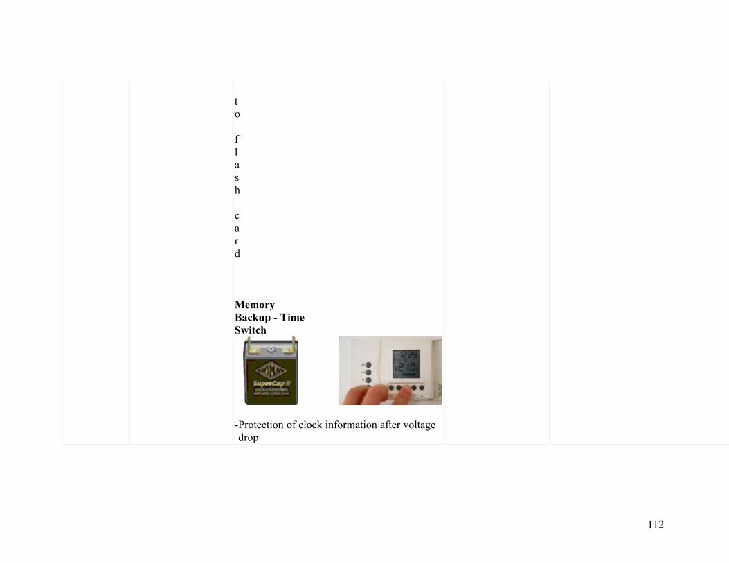
to flash card
Memory Backup - Time Switch
-Protection of clock information after voltage drop
112

WIMA SuperCaps - New Energy
Fields of Application: New Energy (Wind, Solar Systems)
Product Type Application Function Figure Requirements Special Characteristics
SuperCap MC/MR
"customized"
Power Supply
-SuperCap unit supplies local electric systems which need power within short time
Pitch Drive of Windmills
-Continuous adjustment of rotor blade angle
-Pitch control functionally independent of line voltage
-Emergency stop at blackout
-Power supply under extreme weather conditions (-30°C)
-Emergency switch-off system
-Life-time for 20 years
-Low weight -Low maintenance cost
Fast supply of several 100 A up to 3000 A in direct current operation
Operating temperature range from -30°C to +65°C
Many years of maintenance-free operation with clearly more than 500.000 charge/discharge cycles
Life expectancy of more than 15 years
Low weight as against batteries or secondary batteries
Environmentally friendly materials
SuperCap C/R
MC/MR
"customized"
Short-Term Energy Storage
-Intermediate storage of peak-voltage to provide continued power
Short-Term Energy Buffer in Solar Systems
-Energy buffer to avoid downtime after short blackout
-Power supply under extreme weather conditions (-30°C)
-Life-time for 20
113

years-Low weight -Low maintenance cost
114

Recommendation for Processing and Application of SMD Capacitors
Layout Form
The components can generally be positioned on the carrier material as desired. In order to prevent soldering shadows or ensure regular temperature distribution, extreme concentration of the components should be avoided. In practice, it has proven best to keep a minimum distance of the soldering surfaces between two WIMA SMDs of twice the height of the components.As a basic principle for wave soldering, alignment of the soldering surfaces in accordance with the transport direction of the printed circuit board through the soldering wave is recommended.
.
Solder Pad Recommendation
Size codeL
±0.3W
±0.3d
amin.
bmin.
cmax.
181222202824403050406054
4.85.77.210.212.715.3
3.35.16.17.610.213.7
0.50.50.50.50.7
0.7
1.21.21.22.5 2.5
2.5
3.544666
3.54.56.59
11.514
Dims. in mm. The solder pad size recommendations given for each individual series (see SMD series concerned) are to be understood as
115
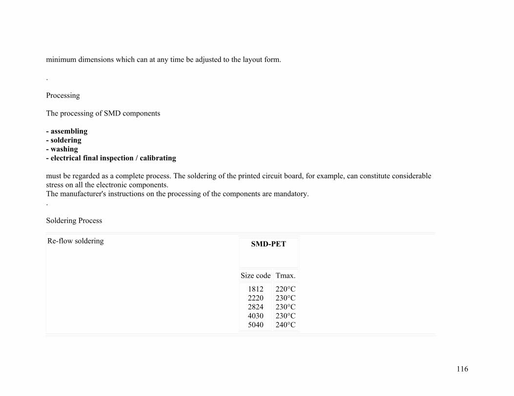
minimum dimensions which can at any time be adjusted to the layout form.
.
Processing
The processing of SMD components
- assembling- soldering- washing- electrical final inspection / calibrating
must be regarded as a complete process. The soldering of the printed circuit board, for example, can constitute considerable stress on all the electronic components.The manufacturer's instructions on the processing of the components are mandatory..
Soldering Process
Re-flow soldering SMD-PET
Size code Tmax.
18122220282440305040
220°C230°C230°C230°C240°C
116
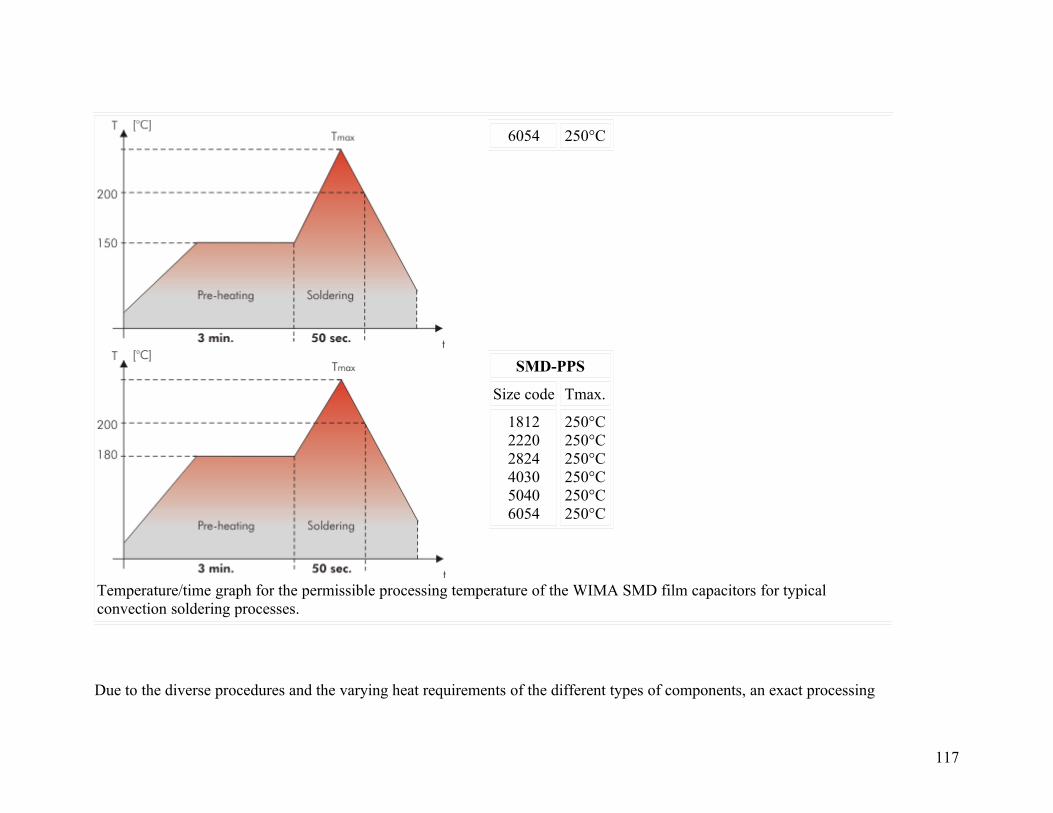
6054 250°C
SMD-PPS
Size code Tmax.
181222202824403050406054
250°C250°C250°C250°C250°C250°C
Temperature/time graph for the permissible processing temperature of the WIMA SMD film capacitors for typical convection soldering processes.
Due to the diverse procedures and the varying heat requirements of the different types of components, an exact processing
117

temperature for re-flow soldering processes cannot be specified. The graph shows the upper limits of temperature and time which must not be exceeded when establishing the solder profile according to your actual requirements.
A max. temperature of T=210°C inside the component should not be exceeded when processing WIMA SMD capacitors.
.
SMD Handsoldering
WIMA SMD capacitors with plastic film dielectric are generally suitable for hand-soldering with a soldering iron where, however, similar to automated soldering processes, a certain duration and temperature should not be exceeded. These parameters are dependent on the physical size of the components and the relevant heat absorption involved.
Size code Temperature°C/°F
Time duration
181222202824403050406054
225/437225/437250/482260/500260/500260/500
2 sec plate 1 / 5 sec off / 2 sec plate 23 sec plate 1 / 5 sec off / 3 sec plate 23 sec plate 1 / 5 sec off / 3 sec plate 25 sec plate 1 / 5 sec off / 5 sec plate 25 sec plate 1 / 5 sec off / 5 sec plate 25 sec plate 1 / 5 sec off / 5 sec plate 2
The above data are to be regarded as guideline values and should serve to avoid damage to the dielectric caused by excessive heat during the soldering process. The soldering quality depends on the tool used and on the skill and experience of the person with the soldering iron in hand.
118

.
Solder Paste
To obtain the best soldering performance we suggest the use of following solder paste alloy:
Lead-free solder pasteSn -BiSn - Zn (Bi)Sn - Ag - Cu (recommended)
Solder paste with leadSn - Pb - Ag (Sn60-Pb40-A, Sn63-Pb37-A) .
Washing
Basically, all plastic encapsulated components, irrespective of the brand cannot be considered as being hermetically sealed. They are therefore only suitable for industrial washing processes to a limited extent.During the washing process, washing agents can penetrate the interior of the component by capillary action through microcracks which might have occurred.This is dependent on a number of parameters e.g.
- washing agents- viscosity of the washing solvent- temperature/time of the washing process- mechanical washing aids such as- ultrasonic- water pressure- rinsing and spraying pressure
119

The type of washing agent to be used is largely specific to the individual user or is often laid down by the manufacturer of the washing equipment. The aggressiveness of the washing agent to be used can thus only be judged in appropriate test series relating to each individual washing process. By and large, the basic rule is that the washing process should be carried out as gently as possible.
.
Drying
During the washing process, aqueous solutions can penetrate the component. This can lead to changes of the electrical parameters. Suitable drying measures should ensure that no residual moisture or traces of washing substances are left in the component. .
Initial Operation / Calibration of the Device
Due to the stress which the components are subjected to during processing, reversible parameter changes occur in almost all electronic components. The capacitance recovery accuracy to be expected with careful processing is within a scope of
| C/C| < 5%
For the initial operation of the device a minimum storage time of
t > 24 hours
is to be taken into account. With calibrated devices or when the application is largely dependent on capacitance it is advisable to prolong the storage time to
t > 10 days
120

In this way ageing effects of the capacitor structure can be anticipated. Parameter changes due to processing are not to be expected after this period of time. .
Humidity Protection Bags
Taped WIMA SMD capacitors are shipped in humidity protection bags according to JEDEC standard, level 1 (EMI/static-shielding bags conforming to MIL-B 81705, Type 1, Class 1). Under controlled conditions the components can be stored two years and more in the originally sealed bag. Opened packing units should be consumed instantly or resealed for specific storage under controlled conditions. .
Reliability
Taking account of the manufacturer's guidelines and compatible processing, the WIMA SMD stand out for the same high quality and reliability as the analogous through-hole WIMA series. The technology of metallized film capacitors used e.g. in WIMA SMD achieves the best values for all fields of application.The expected value is about:
< 2 fit
Furthermore the production of all WIMA components is subject to the regulations laid down by ISO 9001:2000 as well as the guidelines for component specifications set out by IEC quality assessment system (IECQ-CECC) for electronic components. .
Electrical Characteristics and Fields of Application
Basically the WIMA SMD series have the same electrical characteristics as the analogous through-hole WIMA capacitors.Apart from the advantages shown in the diagrams of the electrical parameters in comparison with X7R ceramic
121
and tantalum capacitors, WIMA SMD capacitors have a number of other outstanding qualities compared to ceramic or tantalum dielectrics:
favourable pulse rise timelow ESRlow dielectric absorptionavailable in high voltage serieslarge capacitance spectrumstand up to high mechanical stressgood long-term stability
As regards technical performance as well as quality and reliability, the WIMA SMD series offer the possibility to cover nearly all applications of conventionally through-hole film capacitors with SMD components. Furthermore, the WIMA SMD series can now be used for all the demanding capacitor applications for which, in the past, the use of through-hole components was mandatory:
measuring techniquesoscillator circuitsdifferentiating and integrating circuitsA/D or D/A transformerssample and hold circuitsautomotive electronics
With the WIMA SMD programme available today, the major part of all plastic film capacitors can be replaced by WIMA SMD components. The field of application ranges from standard coupling capacitors to use in switch-mode power supplies as filter or charging capacitors with high voltage and capacitance values, as well as in telecommunications e.g. the well-known telephone capacitor 1µF/250VDC.
122
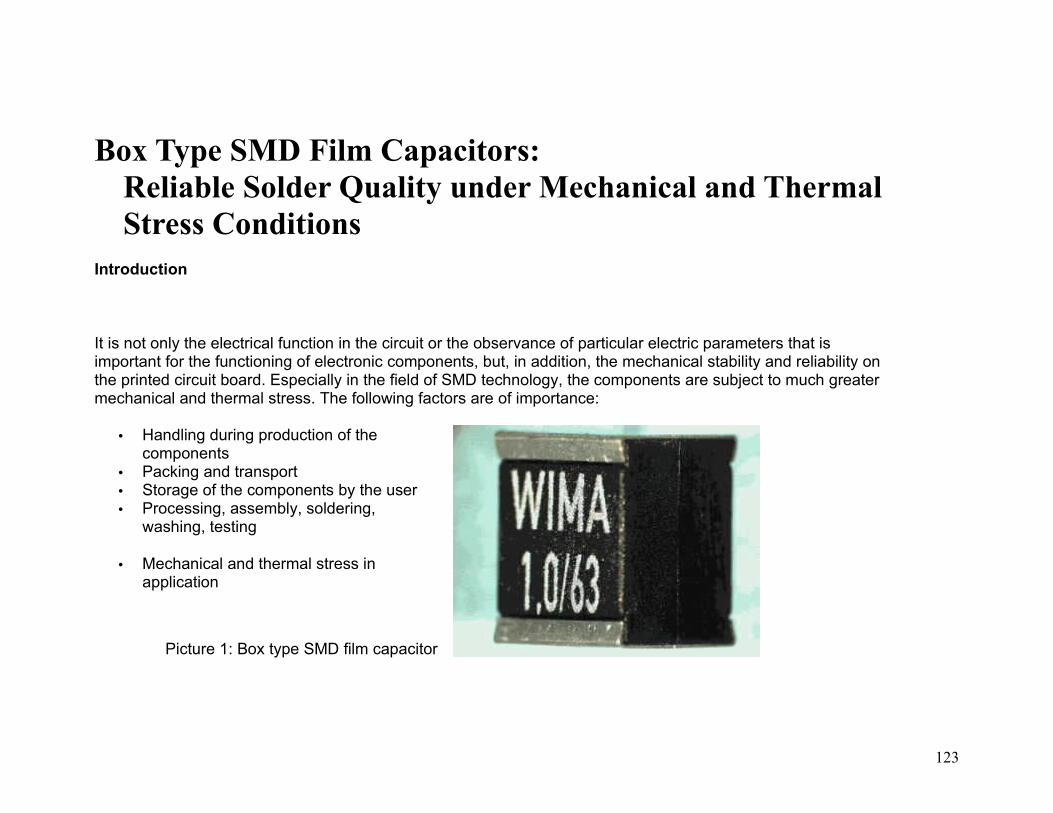
Box Type SMD Film Capacitors:Reliable Solder Quality under Mechanical and Thermal Stress Conditions
Introduction
It is not only the electrical function in the circuit or the observance of particular electric parameters that is important for the functioning of electronic components, but, in addition, the mechanical stability and reliability on the printed circuit board. Especially in the field of SMD technology, the components are subject to much greater mechanical and thermal stress. The following factors are of importance:
• Handling during production of the components
• Packing and transport• Storage of the components by the user • Processing, assembly, soldering,
washing, testing
• Mechanical and thermal stress in application
Picture 1: Box type SMD film capacitor
123

Increased Stress Factors for SMD Components
Conventional wired components are subject to much lower stress. The criteria of packing, transport and storing may be considered equivalent, but the stress factors during processing and application differ considerably.
When being assembled, wired components can be held and guided by the terminating wires. Except for possible slight tension on the wires, mechanical stress does not occur on the active part of the component.
In contrast to this, during the assembly process the SMD components are usually handled by pick and place equipment by means of vacuum suction on the component body and placed on the appropriate solder pad on the printed circuit board. The resulting mechanical stress has a direct effect on the component. The component case, or, in the case of non-encapsulated types, the body of the component has to absorb the resulting stress forces.
Whereas in the case of the conventional wired component, the wire had the function of establishing the contact with the printed circuit board / solder joint or with the circuit, as well as fixing and holding the component, the SMD versions are soldered directly via the end contacts onto the appropriate solder pads of the printed board. In addition, the wire was able to take up and absorb the mechanical stress so that it did not reach the active part of the component. Both the solder joint and the component remained, by and large, unaffected by mechanical stress.
With SMD components, however, mechanical stress caused by the effect of outside forces such as vibration, bumps, warping of the circuit board, and also thermo-mechanical pressure or tension caused by differing coefficients of expansion between the printed circuit board and the component, have a direct effect on the component and the solder joint.
In addition, the much higher thermal stress during the soldering process of SMDs due to the integrated heating of the whole circuit board with the assembled components, must be emphasized.
124

Thus, thermal and mechanical strength, as well as the way the contact is carried out together with the electrical properties, are important criteria for the evaluation of SMD components.
Substitution of Obsolete Polycarbonate (PC) Capacitors After the discontinuation of Polycarbonate film (end of 2000) as a capacitor dielectric by the only manufacturer, Bayer AG/Germany, we have removed all MKC ranges (metallized capacitors) and FKC ranges (film and foil construction) using this capacitor film from our range of products latest after inventory of film has run out.However, the question of which capacitors can be used to replace the PC series is still of interest. The following comparisons may be of assistance in making decisions.
The special feature of Polycarbonate (PC) capacitors is the almost constant course of capacitance drift versus temperature and the suitability for special applications in the field of higher frequencies respectively.
Capacitance change with temperature Dissipation factor with frequency
125
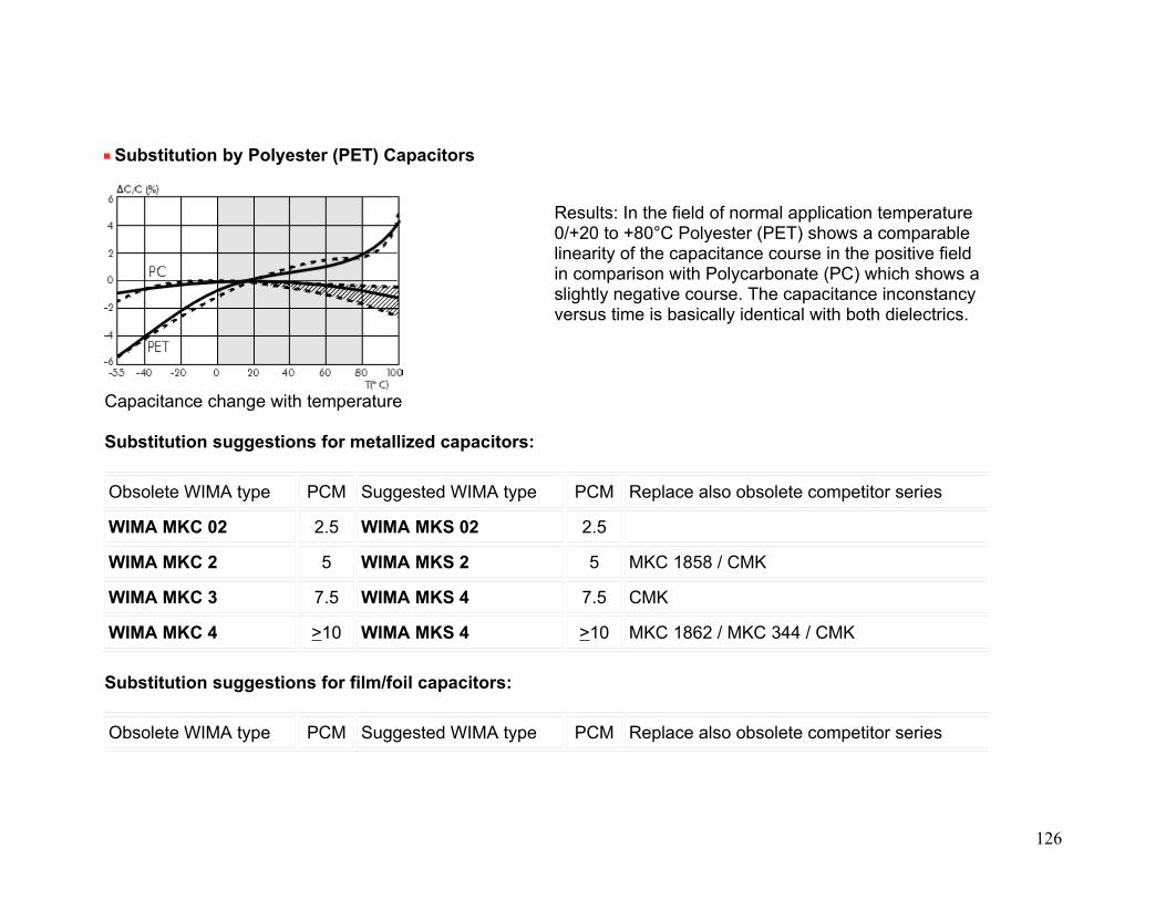
Substitution by Polyester (PET) Capacitors
Results: In the field of normal application temperature 0/+20 to +80°C Polyester (PET) shows a comparable linearity of the capacitance course in the positive field in comparison with Polycarbonate (PC) which shows a slightly negative course. The capacitance inconstancy versus time is basically identical with both dielectrics.
Capacitance change with temperature Substitution suggestions for metallized capacitors:
Obsolete WIMA type PCM Suggested WIMA type PCM Replace also obsolete competitor series
WIMA MKC 02 2.5 WIMA MKS 02 2.5
WIMA MKC 2 5 WIMA MKS 2 5 MKC 1858 / CMK
WIMA MKC 3 7.5 WIMA MKS 4 7.5 CMK
WIMA MKC 4 >10 WIMA MKS 4 >10 MKC 1862 / MKC 344 / CMK
Substitution suggestions for film/foil capacitors:
Obsolete WIMA type PCM Suggested WIMA type PCM Replace also obsolete competitor series
126
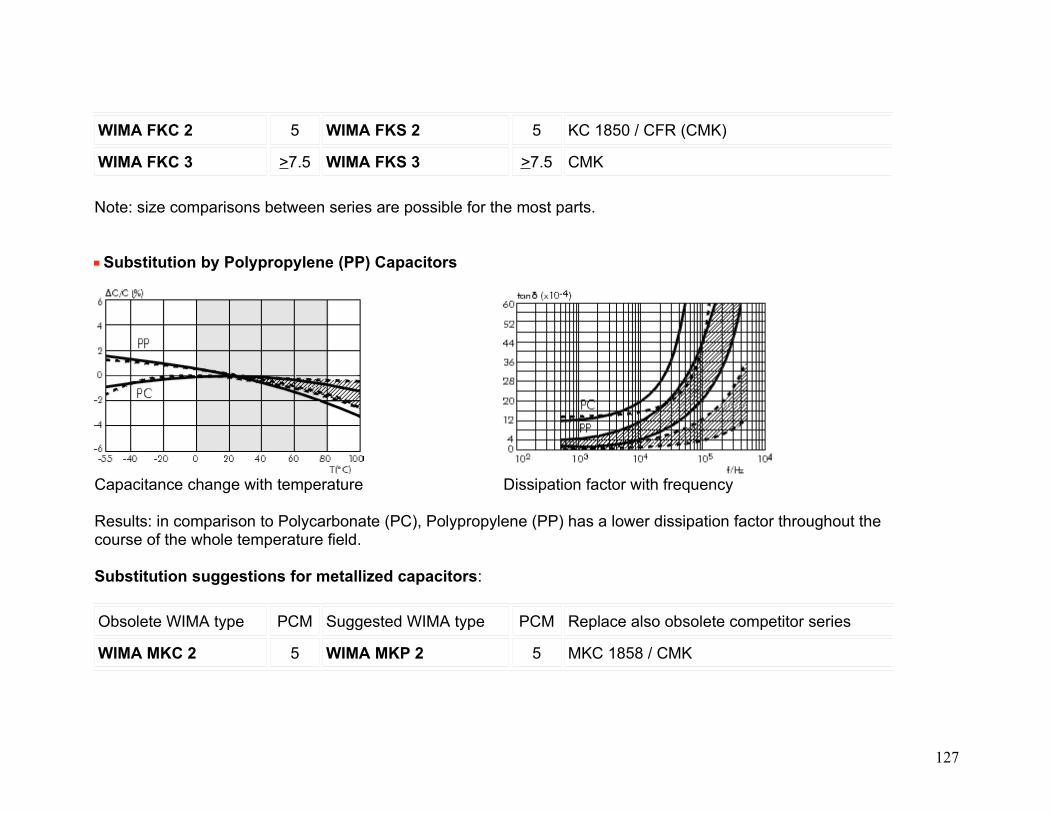
WIMA FKC 2 5 WIMA FKS 2 5 KC 1850 / CFR (CMK)
WIMA FKC 3 >7.5 WIMA FKS 3 >7.5 CMK
Note: size comparisons between series are possible for the most parts.
Substitution by Polypropylene (PP) Capacitors
Capacitance change with temperature Dissipation factor with frequency Results: in comparison to Polycarbonate (PC), Polypropylene (PP) has a lower dissipation factor throughout the course of the whole temperature field. Substitution suggestions for metallized capacitors:
Obsolete WIMA type PCM Suggested WIMA type PCM Replace also obsolete competitor series
WIMA MKC 2 5 WIMA MKP 2 5 MKC 1858 / CMK
127

WIMA MKC 3 7.5 WIMA MKP 4 7.5 CMK
WIMA MKC 4 >10 WIMA MKP 4 >10 MKC 1862 / MKC 344 / CMK
WIMA MKC 10 >7.5 WIMA MKP 10 >7.5
Substitution suggestions for film/foil capacitors:
Obsolete WIMA type PCM Suggested WIMA type PCM Replace also obsolete competitor series
WIMA FKC 02 2.5 WIMA FKP 02 2.5
WIMA FKC 2 5 WIMA FKP 2 5 KC 1850 / CFR (CMK)
WIMA FKC 3 >7.5 WIMA FKP 3 >7.5 CMK
Note: size comparisons between series are possible for the most parts.
Radial Box versus Radial Dipped Capacitor Technologies The origins of radial box film capacitor technology lie in radial dipped film technology, which was first developed by WIMA and other European manufacturers in the early-middle 1960s. The radial design offered obvious advantages over the axial design. These included board real estate savings as well as improved electrical performance (lower ESR and self inductance) and did not require the leads to be bent in order for the part to be inserted on the printed circuit board.
1962 Radial dipped
1963 Moulded case
128
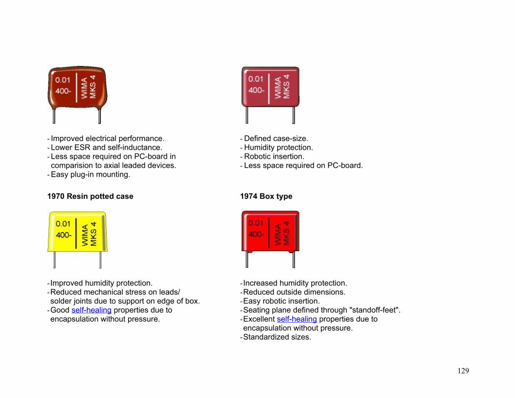
- Improved electrical performance.- Lower ESR and self-inductance.- Less space required on PC-board incomparision to axial leaded devices.
- Easy plug-in mounting.
- Defined case-size.- Humidity protection.- Robotic insertion.- Less space required on PC-board.
1970 Resin potted case
-Improved humidity protection.-Reduced mechanical stress on leads/solder joints due to support on edge of box.
-Good self-healing properties due toencapsulation without pressure.
1974 Box type
-Increased humidity protection.-Reduced outside dimensions.-Easy robotic insertion.-Seating plane defined through "standoff-feet".-Excellent self-healing properties due toencapsulation without pressure.
-Standardized sizes.
129

Humidity Protection
The poreous epoxy coating of radial dipped film capacitors cannot be expected to provide reliable humidity protection where moderate to severe humidity conditions exist, even when potting compound such as bitumen is used. In addition, since there is no clearly defined seating plane, components rest on the "laquered pants" that can and do develop fissures at the lead exit points when parts are automatically inserted, thus further compromising their ability to resist the effects of humidity.
Box type-Two casting steps guarantee high humidity protection.
-Homogenous encapsulation without air enclosures.
-Case and lead exit points secure from high humidity.
-Additional protection by cast sealing is not necessary.
Dipped version-Very porous coating with visible air enclosures.-Mechanical stress during insertion leads to cracks around the lead exit points.
-Insufficient humidity protection due to thin and irregular encapsulation.
-Bitumen or tar casting does not provide the expected protection.
130

Uniform Dimensions
Radial box film capacitor provides uniform dimensions for purposes of optimizing space and second sourcing. Further, it allows for greater flexibility in automatic insertion including robotic insertion of larger parts.
Box type-All dimensions clearly defined.-Allows for close placement of parts.-Easy second source because of standardized box size.
Dipped version-Only lead spacing is defined. -All other dimensions are undefined.-No standardized body sizes (second source).-Need of additional space between the parts due to variations of lead exit points and body dimensions.
Exact Setting on PC-Board
131

Since radial dipped film capacitors rest on their leads rather than on the case or "standoff-feet", any vibration that the capacitor element may be experiencing will be transmitted through the leads to the solder joints. This is of particular concern in AC applications where self-generated electro-mechanical vibrations accelerate the ageing of the solder joints.
Box type-Capacitors rest on "standoff-feet".-No stress on leads.-Electro-mechanical vibrations do not impact solder joints.-Exact setting on PC-board.-Small footprint on PC-board.
Dipped version-Capacitors rest on solder joints.-Electro-mechanical vibrations can lead to accelerated ageing of solder joints.
-More space required to avoid short circuits.
Flammability Resistance
The extremely thin covering, plus the presence of air pockets contained within the coating, makes the dipped film
132
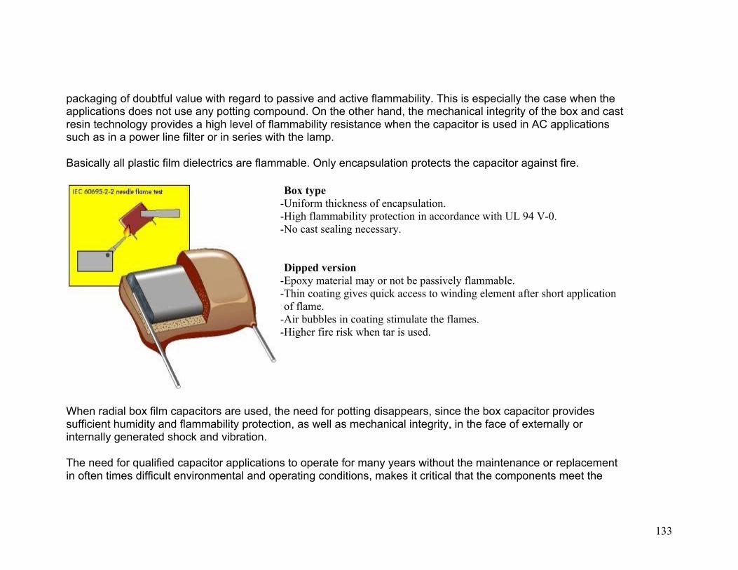
packaging of doubtful value with regard to passive and active flammability. This is especially the case when the applications does not use any potting compound. On the other hand, the mechanical integrity of the box and cast resin technology provides a high level of flammability resistance when the capacitor is used in AC applications such as in a power line filter or in series with the lamp.
Basically all plastic film dielectrics are flammable. Only encapsulation protects the capacitor against fire.
Box type-Uniform thickness of encapsulation.-High flammability protection in accordance with UL 94 V-0.- No cast sealing necessary.
Dipped version-Epoxy material may or not be passively flammable.-Thin coating gives quick access to winding element after short application of flame.
-Air bubbles in coating stimulate the flames.-Higher fire risk when tar is used.
When radial box film capacitors are used, the need for potting disappears, since the box capacitor provides sufficient humidity and flammability protection, as well as mechanical integrity, in the face of externally or internally generated shock and vibration.
The need for qualified capacitor applications to operate for many years without the maintenance or replacement in often times difficult environmental and operating conditions, makes it critical that the components meet the
133
highest standards of packaging technology. Without such standards, safe and reliable operation over the life of the product cannot be guaranteed. The box film technology is designed to meet this challenge both in radial and SMD version.
Snubber Capacitors for Complete Insurance of Power Semiconductors The trend of modern semiconductor technology towards increasingly powerful applications results in the fact that switched currents and voltage levels are continuously increased and that simultaneously the switching speed is also increasing markedly.The developments in the area of power semiconductors include the component group IGBT (Insulated Gate Bipolar Transistor) or IGBT modules.The switching capacity with shortest switching times which can be realized using IGBTs necessitates an extremely low-inductance circuit design. Even the low self-inductance of the power bus may induce dangerous voltage overshoots between collector and emitter which may result in the destruction of the valuable power semiconductors.
134

Typical voltage overshoot during switch-off.
To protect the components, so-called snubber suppressor circuits are used. The most important component in this respect is a low-inductance pulse capacitor in order to attenuate or cut off peak voltages. In general, three basic snubber circuits are used with IGBTs.
Circuit A
Capacitor
Circuit B
Capacitor-resistor-diode
Circuit C
Capacitor-resistor-diode In this context, the capacitor serves to suppress dangereous induced voltages which are produced during
135

switching of the often very high currents. The most important criteria in selecting such capacitors are
- low self-inductance- low ESR- high pulse load capability- low loss factor
In order to minimize self-inductance it is of importance to be able to install the capacitor as close as possible to the power semiconductor to be protected. Furthermore, a high mechanical stability is necessary due to the often rough environmental conditions existing in industrial applications.
Based on long experience with Polypropylene pulse capacitors in all conceivable applications, the series WIMA Snubber MKP and WIMA Snubber FKP were developed to meet the demands of high-power converter technology and are state-of-the-art components with regard to quality, reliability, and electrical performance. The WIMA Snubber technology is unique
136

Low-loss Polypropylene dielectricHigh pulse load capability due to double-sided metallization or film/foil construction.High voltage / overvoltage strengthLow-inductance design achieved by end-surface contactingVarious connection configurations.Direct-contact terminals for safe contact at high continuous current loadFlame-retardant plastic case, UL 94 V-0
Production sites ISO 9001:2000 certified
WIMA Environmental Policy All WIMA capacitors, irrespective of whether through-hole devices or SMD, are made of environmentally friendly materials. Neither during manufacture nor in the product itself any toxic substances are used, e.g.
LeadPCBCFC
PBB / PBDEArsenicCadmium
137

Hydrocarbon chloridChromium 6+
Mercuryetc.
We merely use pure, recyclable materials for packing our components, such as:
- carton- cardboard- adhesive tape made of paper- polystyrene
We almost completely refrain from using packing materials such as:
- foamed polystyrene (Styropor®) - adhesive tapes made of plastic- metal clips
WIMA Tray Packing System TPS The WIMA Tray Packing System was developed by WIMA to meet the challenge to minimize the waste volume and to prevent special waste by using recyclable materials.
138

Photo 1: Pallet with capacitors removed from a packaging unit. The leads are pointing upwards
Photo 2: To invert, the tray inside the cover of the packaging unit is laid on top of the capacitors
Photo 3: The sandwich system is turned through 180°
Photo 4: Removal of the pallet now leaves the capacitors positioned in the tray with their leds pointing downwards i.e. "the right way round"
With the packing systems developed by WIMA, larger film capacitors are stacked in layers in grey cardboard boxes, without the additional need for inner polystyrene packaging. In this system, the capacitors are protected by plastic inner packing, known as "stacking pallets". These pallets are shaped such that:
• the capacitor leads are protected• high pack density per packaging unit is achieved• the capacitor can be removed from the packaging unit in the pallet form, for assembly• capacitors can be held ready at the assembly site in pallet form with the leads upwards or downwards, as
required by the user.
139

Other advantages of the system are that the storage space required can be reduced and that no additional devices or operations are required to prepare the capacitors for manual assembly.
A significant reduction of packaging waste results because the packaging consists only of cardboard, paper adhesive tape and recyclable polystyrene.
WIMA is also offering its customers a return service for the plastic TPS packing.
WIMA Part Number SystemA WIMA part number consists of 18 digits and is composed as follows:
Field
Field
Field
Field
Field
Field
Field
Field
1 - 4:
5 - 6:
7 - 10:
11 - 12:
13 - 14:
15:
16:
Type description
Rated voltage
Capacitance
Size and PCM
Special features (e.g. Snubber versions)
Capacitance tolerance
Packing
Lead length (untaped)
140

17 - 18:
1 2 3 4 5 6 7 8 9 10 11 12 13 14 15 16 17 18
M K S 2 C 0 2 1 0 0 1 A 0 0 M S S D
MKS 2 63 VDC 0.01 µF 2.5 x 6.5 x 7.2
- 20% bulk 6-2
Type description:
SMD-PET
SMD-PPS
FKP 02
MKS 02
FKS 2
FKP 2
MKS 2
MKP 2
= SMDT
= SMDI
= FKP0
= MKS0
= FKS2
= FKP2
= MKS2
= MKP2
Nominal voltage:
2.5 VDC
4 VDC
14 VDC
28 VDC
40 VDC
5
= A1
= A2
= A3
= A4
= A5
=
Capacitance:
22 pF
47 pF
100 pF
150 pF
220 pF
330 pF
470 pF
680 pF
= 0022
= 0047
= 0100
= 0150
= 0220
= 0330
= 0470
= 0680
Size:
4.8 x 3.3 x 3 Size 1812
4.8 x 3.3 x 4 Size 1812
5.7 x 5.1 x 3.5 Size 2220
5.7 x 5.1 x 4.5 Size 2220
7.2 x 6.1 x 3 Size 2824
7.2 x 6.1 x 5 Size 2824
10.2 x 7.6 x 5 Size 4030
12.7 x 10.2 x 6 Size 5040
= X1
= X2
= Y1
= Y2
= T1
= T2
= K1
= V1
Special features :
Standard
Version A1
Version A1.1.1
Version A1.3.1
Version A1.3.2
Version A1.4
Version A1.4.1
Version A1.5
= 00
= 1A
= 1B
= 1D
= 1E
= 1F
= 1G
= 1H
Tolerance:
20%
10%
5%
2.5%
1%
...
= M
= K
= J
= H
= E
Packing:
AMMO H16.5 340 x 340
AMMO H16.5 490 x 370
AMMO H18.5 340 x 340
AMMO H18.5 490 x 370
REEL H16.5 360
REEL H16.5 500
REEL H18.5 360
REEL H18.5 500
= A
= B
= C
= D
= F
= H
= I
= J
Lead length:
(untaped)3.5 ±0.5
6 -2
16 ±1
...
141

FKS 3
FKP 3
MKS 4
MKP 4
MKP 10
FKP 4
FKP 1
MKP-X2
MKP-X2 R
MKP-Y2
MP 3-X2
MP 3-X1
MP 3-Y2
MP 3R-Y2
Snubber MKP
= FKS3
= FKP3
= MKS4
= MKP4
= MKP1
= FKP4
= FKP1
= MKX2
= MKXR
= MKY2
= MPX2
= MPX1
= MPY2
= MPYR
= SNMP
VDC
50 VDC
63 VDC
100 VDC
160 VDC
250 VDC
400 VDC
450 VDC
600 VDC
630 VDC
700
A6
= B0
= C0
= D0
= E0
= F0
= G0
= H0
= I0
= J0
=
1000 pF
1500 pF
2200 pF
3300 pF
4700 pF
6800 pF
0.01 µF
0.022 µF
0.047 µF
0.1 µF
0.22 µF
0.47 µF
1 µF
2.2 µF
4.7 µF
= 1100
= 1150
= 1220
= 1330
= 1470
= 1680
= 2100
= 2220
= 2470
= 3100
= 3220
= 3470
= 4100
= 4220
= 4470
15.3 x 13.7 x 7 Size 6054
2.5 x 7 x 4.6 PCM 2.5
3 x 7.5 x 4.6 PCM 2.5
3.8 x 8.5 x 4.6 PCM 2.5
2.5 x 6.5 x 7.2 PCM 5
3 x 7.5 x 7.2 PCM 5
3.5 x 8.5 x 7.2 PCM 5
2.5 x 7 x 10 PCM 7.5
3 x 8.5 x 10 PCM 7.5
4 x 9 x 10 PCM 7.5
3 x 9 x 13 PCM 10
4 x 9 x 13 PCM 10
4 x 9.5 x 13 PCM 10
5 x 11 x 18 PCM 15
6 x 12.5 x 18 PCM 15
= Q1
= 0B
= 0C
= 0D
= 1A
= 1B
= 1C
= 2A
= 2B
= 2C
= 3A
= 3C
= 3D
= 4B
= 4C
...
ROLL H16.5
ROLL H18.5
BLISTER W12 180
BLISTER W12 330
BLISTER W16 330
BLISTER W24 330
Bulk Mini
Bulk Standard
Bulk Maxi
TPS Mini
TPS Standard
...
= N
= O
= P
= Q
= R
= T
= M
= S
= G
= X
= Y
142

Snubber FKP
GTO MKP
DC-LINK MKP 4
DC-LINK MKP C
DC-LINK HC
SuperCap C
SuperCap MC
SuperCap R
SuperCap MR
= SNFP
= GTOM
= DCP4
= DCPC
= DCH_
= SCSC
= SCMC
= SCSR
= SCMR
VDC
800 VDC
850 VDC
900 VDC
1000 VDC
1100 VDC
1200 VDC
1250 VDC
1500 VDC
1600 VDC
2000
K0
= L0
= M0
= N0
= O1
= P0
= Q0
= R0
= S0
= T0
=
10 µF
22 µF
47 µF
100 µF
220 µF
1 F
2.5 F
50 F
100 F
110 F
600 F
1200 F
...
= 5100
= 5220
= 5470
= 6100
= 6220
= A010
= A025
= A500
= B100
= B110
= B600
= C120
7 x 14 x 18 PCM 15
5 x 14 x 26.5 PCM 22.5
6 x 15 x 26.5 PCM 22.5
7 x 16.5 x 26.5 PCM 22.5
9 x 19 x 31.5 PCM 27.5
11 x 21 x 31.5 PCM 27.5
13 x 24 x 31.5 PCM 27.5
9 x 19 x 41.5 PCM 37.5
11 x 22 x 41.5 PCM 37.5
13 x 24 x 41.5 PCM 37.5
94 x 49 x 182 DCH_
94 x 77 x 182 DCH_
...
= 4D
= 5A
= 5B
= 5D
= 6A
= 6B
= 6D
= 7A
= 7B
= 7C
= H0
= H1
143

VDC
2500 VDC
3000 VDC
4000 VDC
6000 VDC
250 VAC
275 VAC
300 VAC
400 VAC
440 VAC
500
U0
= V0
= W0
= X0
= Y0
= 0W
= 1W
= 2W
= 3W
= 4W
=
144

VAC
...
5W
The data on this page is not complete and serves only to explain the part number system. Part number information is listed on the pages of the respective WIMA range.
145