super pwrgate pg40s - west mountain radio · large batteries have side, post, or ... it charges the...
TRANSCRIPT

www.westmountainradio.com1020 Spring City DriveWaukesha, WI 53186
©2017 West Mountain Radio, All rights reserved. All trademarks are the property of their respective owners.
Super PWRgatePG40S

2West Mountain Radio Operating Manual
INTRODUCTIONThank you for choosing the Super PWRgate PG40S….the high power OR Gate with a built-in four-stage battery charger. It makes a true solid-state UPS for the ham shack.
The Super PWRgate eliminates the danger of connecting a power supply directly across a battery, which can damage many power supplies. The Super PWRgate also avoids introducing hum and RF interference, caused by most lead-acid battery chargers, by using a linear regulator. Furthermore, most lead-acid battery chargers are designed for flooded lead-acid marine or automotive batteries, and are inappropriate for charging sealed lead-acid gel and AGM type batteries. The Super PWRgate will extend the life span of a sealed lead-acid battery compared to using a flooded lead- acid charger.
The Super PWRgate transfers 40 amperes at 12 volts DC in a continuous safe manner. It connects a battery and a power supply to a load, while electrically isolating both the battery and the supply from each other. Whenever the power supply is on, the supply feeds the load. It also charges the battery with a high-current four-state safe battery charger. Whenever the power supply is off, the battery will feed the load. If either the power supply or the battery is malfunctioning, neither draws current from the other. The switching is instantaneous.
A Super PWRgate is very useful in the ham shack, and even more useful in a repeater installation. Communication equipment will remain operative during AC power blackouts and power supply failures. Power supplies and batteries can be swapped out while equipment continues to be powered and without glitches.
Additionally, the Super PWRgate and a power supply may be used solely as a permanently installed battery charger. This also may be configured to run a radio station directly from the battery.
The Super PWRgate is designed for the following battery types:• Gel - Sealed lead-acid, not AGM• AGM - Sealed lead-acid, Absorbed Glass Mat (lighter weight and less
expensive; fewer charge/discharge cycles than Gel)
Please read the following instructions BEFORE installing the Epic

3West Mountain Radio Operating Manual
INTR
OD
UC
TION
Super PWRgate PG40S Features• Instant switch from a power supply to/from a battery• Built-in Four-State battery charger with selectable current rates of 1, 4, 7
and 10 amperes• The battery and power supply are isolated from each other• Provides forward voltage drop of less than 0.3 volts at 20 amperes and
0.37 volts at 40 amperes• Solid, durable construction in an aluminum case with heat sink and
includes mounting holes.
Package Contents• Super PWRgate PG40S Unit• 4 Rubber Feet• User Manual
The following may damage the unit:• Be very careful to connect positive to positive and negative to negative
for all connectors - or it may result in equipment damage.• Use a safety fuse in close proximity to the battery to prevent
overheating, fire, or explosion.• Do not mount the Super PWRgate on a surface that may melt.• Do not adjust any of the screws (including the plastic screw) on the
bottom of the unit - when loosened, the unit may overheat.• The Super PWRgate is not waterproof.• The fuses on the Super PWRgate do not protect the unit, the battery, or
equipment. The fuses are used as switches.
WARNINGS
4West Mountain Radio Operating Manual
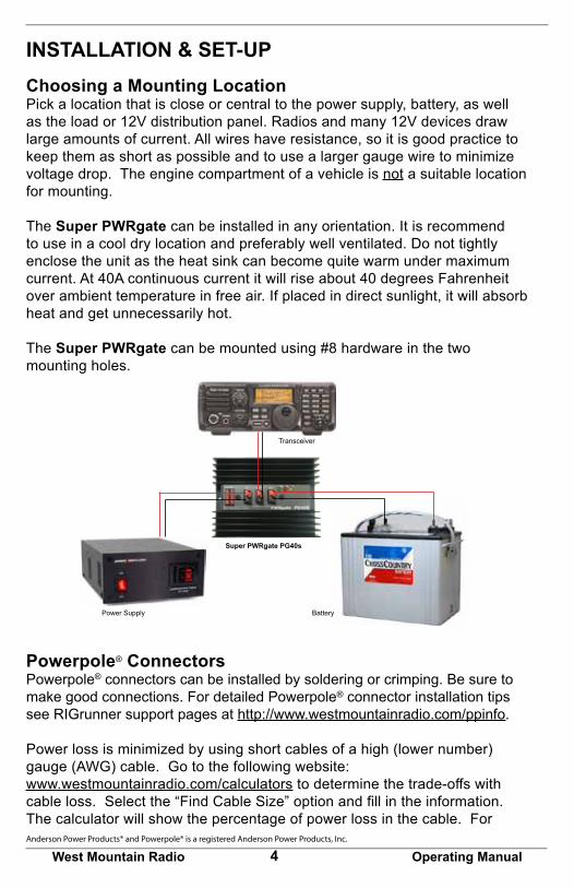
INSTALLATION & SET-UPChoosing a Mounting LocationPick a location that is close or central to the power supply, battery, as well as the load or 12V distribution panel. Radios and many 12V devices draw large amounts of current. All wires have resistance, so it is good practice to keep them as short as possible and to use a larger gauge wire to minimize voltage drop. The engine compartment of a vehicle is not a suitable location for mounting.
The Super PWRgate can be installed in any orientation. It is recommend to use in a cool dry location and preferably well ventilated. Do not tightly enclose the unit as the heat sink can become quite warm under maximum current. At 40A continuous current it will rise about 40 degrees Fahrenheit over ambient temperature in free air. If placed in direct sunlight, it will absorb heat and get unnecessarily hot.
The Super PWRgate can be mounted using #8 hardware in the two mounting holes.
Powerpole® ConnectorsPowerpole® connectors can be installed by soldering or crimping. Be sure to make good connections. For detailed Powerpole® connector installation tips see RIGrunner support pages at http://www.westmountainradio.com/ppinfo.
Power loss is minimized by using short cables of a high (lower number) gauge (AWG) cable. Go to the following website: www.westmountainradio.com/calculators to determine the trade-offs with cable loss. Select the “Find Cable Size” option and fill in the information. The calculator will show the percentage of power loss in the cable. For Anderson Power Products® and Powerpole® is a registered Anderson Power Products, Inc.
Power Supply
Transceiver
Battery
Super PWRgate PG40s

5West Mountain Radio Operating Manual
INSTA
LLATION
& SET-U
P
example, at 100W, a 6 foot 10 AWG cable will have a 2% loss; whereas a 16 AWG cable will have 8% loss.
CablesThe wire should be heavy gauge and as short as possible; recommend #10 wire. Most power supplies have 1/4 inch studs. Note that West Mountain Radio carries 3, 6 and 10 feet long power supply cables, #10 red and black insulated wire with 1/4 inch ring terminals on one end and Powerpole® on the other.
Be sure to connect the RED Powerpole connects to the RED wire and connect to the PLUS terminal. Similarly, make sure that the BLACK Powerpole® connect to the BLACK wire and connect to the NEGATIVE terminal. Check that the connections are well tightened.
Confirm that the Powerpole® are plugged together securely, and that the wire is straight at the connection point and is not under strain or bent over.
Power Supply - Connectors are intended for a power supply connected to AC. The normal voltage is 13.8V to 14.5V. It is recommended this voltage be higher than the charge voltage for the battery being used: 14.1V for a Gel and 14.5V for an AGM. Expect the voltage to the equipment to be one-third of a volt below this voltage. The unit will operate under battery power if no power is on this input.
Plug the cable from the power supply into the Super PWRgate connector marked PS.
Connecting the BatteryA fuse must be installed in the positive lead directly at the battery terminal. Note,anyshortinthebatterywire,connector,orloadcouldresultinfireand battery explosion.
Caution: Handle batteries with knowledge and appropriate care. Batteries have dangerous chemicals that can seep out. Batteries can emit extremely explosive hydrogen gas. Batteries, especially automotive andmarinefloodedleadacid,mustbeusedinastrong,ventilatedenclosure. Sealed lead acid batteries are much safer but must be correctly handled with care.
NEVER make the last connection directly to a battery causing a spark that could cause the battery to explode, sending debris and acid in all directions. Batteries can get very hot when improperly charged or if a cell gets shorted. Batteries will explode during charging or discharging for a variety of reasons. Batteries are safe when handled properly.

6West Mountain Radio Operating Manual
Choose a 12 volt battery with an ampere-hour rating according to your power needs. If the batteries are placed indoors they must be sealed for safety reasons. Again, it is very important to place a fuse at the positive battery terminal. Additional assistance may be found: http://www.westmountainradio.com/capacity_calculator.php
West Mountain Radio carries size 24 Gel and AGM batteries, as well as smaller and larger batteries.
Large batteries have side, post, or threaded terminals. Deep cycle, marine, AGM, and others usually have 3/8 inch and 5/16 inch studs. Therefore, it is recommended to use a short 3 feet #10 wire, Powerpole® on one end, an in-line fuse (40-50A), and ring terminals for the battery end. West Mountain Radio carries a battery fuse kit, wire, and Powerpole®.
Fully charged 12 volt Lead Acid batteries exhibit around 13.5 volts open circuit. When supplying current, the battery’s internal resistance diminishes the voltage. For instance, a 70 Ah battery will drop to 12.3 volts at 10 amperes at half discharge.
The power supply can be adjusted to allow for a maximum charge to the battery. Use a good voltmeter to get an accurate reading. Most power supplies have an internal pot, even if it is a fixed voltage supply. Read the service and calibration manual for instructions for each power supply.
All major radio manufacturers specify that the radio will operate up to 15 volts DC. Therefore, using the Super PWRgate at an elevated voltage should not harm the equipment. Vehicle alternators also will supply a higher voltage for battery charging.
Gel CellsAdjust the power supply to 14.1V to achieve a full charge. The internal jumper should not be installed. This is the factory default setting when shipped.
AGM CellsAdjust the power supply to 14.5V to achieve a full charge. Install the AGM jumper inside the Super PWRgate unit.
Connecting the Load or Power StripOutput - Connectors are intended to power equipment. It may go to a single piece of equipment or to a distribution panel (i.e. RIGrunner). There is no fuse or internal current limiting.
Manufacturers list the lowest recommended DC supply voltage range for the specific radio model. Some radios are listed as 13.8 VDC +- 15%, and others as 13.8 VDC +-10%. 12 volt power supplies are regulated to provide 13.8
7West Mountain Radio Operating Manual
INSTA
LLATION
& SET-U
P
volts DC. The Super PWRgate voltage drop is approximately one-third of a volt.
If connecting directly to a radio or other device, you will need to install Powerpole® on those cords. Modern radios use RED wire for positive, and BLACK wire for negative (or common or ground). Refer to the equipment manual if you have non-standard equipment. Plug this wire into the Super PWRgate terminal marked OUT.
If you are connecting the output to a power strip, such as a RIGrunner, it is recommended to use #10 wire. At least one end will need Powerpole® installed; the other end can wire directly to the power strip or use connectors. Note that West Mountain Radio carries 3, 6, and 10 feet long extension cables, #10 red and black insulated wire, with Powerpole® on both ends.
System CheckoutWhen the power supply and battery are connected, and the Super PWRgate is driving a radio, a quick checkout procedure should be followed:
· Run your radio, and unplug the power supply. The radio should operate without interruption now from the battery.
· Plug the power supply back in, and the radio will now be powered from the supply. If you have an ammeter on the supply it will show current.
An in-line meter, such as PWRcheck by West Mountain Radio, may be used to measures volts, amperes, watts, ampere-hours, and watt-hours simultaneously.
Place the PWRcheck in series with the battery to get an accurate reading of the charge current. Unplug the load from the Super PWRgate to measure the battery’s charging current. Refer to the charging circuit description to verify the different states when measuring the charging current.
Super PWRgate ChargerThe charging circuit is a four-state high-current battery charger. The charging circuit, which is always connected to the battery, uses the power supply as the current source. It charges the battery automatically by knowing the battery’s voltage. It also changes charging state if the power supply goes from “off” to “on”, following a power outage, and it also changes state if the battery voltage drops when supplying heavy current. These conditions are interrelated to provide proper charging automatically.
The charger is a safe battery charger. It supplies the rated current if the battery is heavily discharged. Current drops in a smooth and progressively diminishing manner as the battery nears full charge. Note, that the charger is a feedback
8West Mountain Radio Operating Manual
device and it cannot overcharge a 12 volt battery. Also, it will not charge a battery that has a dead cell. The charging circuit has four selectable charging current settings, 1A, 4A, 7A, and 10A, to be chosen appropriately for the battery’s rating.
The four charging states are:
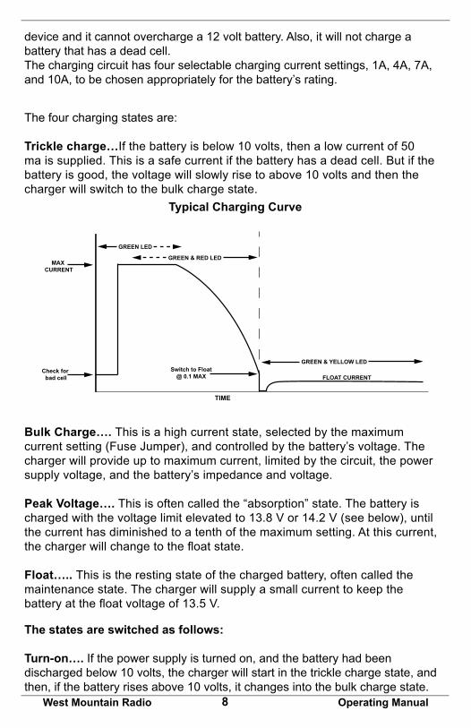
Trickle charge…If the battery is below 10 volts, then a low current of 50 ma is supplied. This is a safe current if the battery has a dead cell. But if the battery is good, the voltage will slowly rise to above 10 volts and then the charger will switch to the bulk charge state.
Bulk Charge…. This is a high current state, selected by the maximum current setting (Fuse Jumper), and controlled by the battery’s voltage. The charger will provide up to maximum current, limited by the circuit, the power supply voltage, and the battery’s impedance and voltage.
Peak Voltage…. This is often called the “absorption” state. The battery is charged with the voltage limit elevated to 13.8 V or 14.2 V (see below), until the current has diminished to a tenth of the maximum setting. At this current, the charger will change to the float state.
Float….. This is the resting state of the charged battery, often called the maintenance state. The charger will supply a small current to keep the battery at the float voltage of 13.5 V.
The states are switched as follows:
Turn-on…. If the power supply is turned on, and the battery had been discharged below 10 volts, the charger will start in the trickle charge state, and then, if the battery rises above 10 volts, it changes into the bulk charge state.
Typical Charging Curve
Switch to Float@ 0.1 MAX
GREEN & YELLOW LED
FLOAT CURRENT
MAX CURRENT
GREEN LED
GREEN & RED LED
Check for bad cell
TIME
9West Mountain Radio Operating Manual
INSTA
LLATION
& SET-U
P
If the voltage rises to above 12 volts, then the peak voltage state is entered. Then, when the current has diminished to one-tenth of the maximum selected current, the float state is entered. If the battery is charged to over 13 volts, turning on the power supply will cause the charger to remain in the float state.
This turn on cycle occurs following a power outage.
Discharging Battery…. If a load is placed on the battery, and the charger had been in the float state, and the battery voltage stays above 13 volts, the charger will remain in the float state supplying up to full current. If the battery voltage is discharged to less than 12 volts, and the load is removed, the charger will enter the peak voltage and eventually the float state as above.
If the radio station is connected directly to the battery and not through the Super PWRgate output, then the battery will supply the load while the battery is being charged. In fact, the current will be shared between the load and the battery. This method of powering a radio station was described by W1ZR in an article in QST, Dec 2003.
LED Indicators
Green (ON)…. Indicates that the charger is fully active and will provide up to maximum current to the battery according to the battery’s state. Note that this LED does not measure nor indicate current flow, only the charger’s state, ie. “fully active state and would charge a battery if it were connected.“
Green (ON) and RED (PK)…. Indicates that the charger is in the peak voltage state (PK) and will provide up to maximum current to the battery. As the current is diminishing the charger attempts to reach an elevated battery voltage. When the current drops to one-tenth the maximum current setting the state changes to float.
Green (ON) and Yellow (FL)…. Indicates that the charger is in the float state (FL) and will provide up to maximum current to the battery to maintain the battery at the float voltage of 13.5 volts.
Choosing and Setting the Maximum Charge Current
The charger has two 40A fuses that are used as a high current switch (need a high current jumper wire. Note that leaving the fuses out provides a charge current of 1 ampere. To get different charging current values install the fuses as follows. 1 Ampere…........No fuse 4 Amperes……..Fuse in left socket 7 Amperes……..Fuse in right socket 10 Amperes……..Fuse in both sockets
10West Mountain Radio Operating Manual
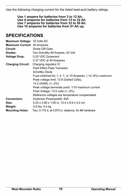
Use the following charging current for the listed lead-acid battery ratings.
Use 1 ampere for batteries from 3 to 12 Ah. Use 4 amperes for batteries from 13 to 32 Ah. Use 7 amperes for batteries from 33 to 50 Ah. Use 10 amperes for batteries from 51 Ah up.
SPECIFICATIONSMaximum Voltage: 18 Volts DCMaximum Current: 40 AmperesCircuit: Diode OR-GateDiodes: Two Schottky 80 Ampere, 20 VoltVoltage Drop: 0.25 VDC Quiescent 0.37 VDC at 40 AmperesCharging Circuit: Charging regulator IC Field Effect Pass Transistor Schottky Diode Fuse switched for 1, 4, 7, or 10 Amperes ( +2,-8%) maximum Peak voltage limit: 13.8 (Gelled Cells), 14.2 (AGM), (+,-2%) Peak voltage terminate point: 1/10 maximum current Float Voltage: 13.5 volts (+,-2%) Reference voltages are temperature compensatedConnectors: Anderson Powerpole®, 40ASize: 5.25 x 3.90 x 1.65 in, 13.4 x 9.9 x 4.2 cm Weight: 0.9 lbs, 0.4 kgMounting Holes: Two, 0.175 d, at 4.875 in. distance, for #8 hardware

11West Mountain Radio Operating Manual
SPECIFIC
ATION
S
Super PWRgate PG40S WarrantySuper PWRgate PG40S is warranted against failure due to defects in workmanship or materials for one year after the date of purchase from West Mountain Radio. Warranty does not cover damage caused by abuse, accident, misuse, improper or abnormal usage, failure to follow instructions, improper installation, alteration, lightning, or other incidence of excessive voltage or current. If failure occurs within this period, return the Super PWRgate PG40S or accessory to West Mountain Radio at your shipping expense. The device or accessory will be repaired or replaced, at our option, without charge, and returned to you at our shipping expense. Repaired or replaced items are warranted for the remainder of the original warranty period. You will be charged for repair or replacement of the Super PWRgate PG40S or accessory made after the expiration of the warranty period.
West Mountain Radio shall have no liability or responsibility to customer or any other person or entity with respect to any liability, loss, or damage caused directly or indirectly by use or performance of the products or arising out of any breach of this warranty, including, but not limited to, any damages resulting from inconvenience, loss of time, data, property, revenue, or profit, or any indirect, special incidental, or consequential damages, even if West Mountain Radio has been advised of such damages.
Except as provided herein, West Mountain Radio makes no express warranties and any implied warranties, including fitness for a particular purpose, are limited in duration to the stated duration provided herein. www.westmountainradio.com 1020 Spring City Drive, Waukesha, WI 53186 tel 262-522-6503 fax 262-522-6504
