suggested designs to facilitate improved management and treatment
TRANSCRIPT

Suggested Designs to Facilitate Improved Management and Treatment
of Ballast Water on New and Existing Ships
by
Alan H TaylorAlan H Taylor and Associates Pty Limited
andDr Geoff Rigby
Reninna Pty Limited
Discussion Paper prepared for Agriculture, Fisheries and Forestry Australia as part ofthe Research Advisory Group Ballast Water Research and Development Program
January 2001

Suggested Designs to Facilitate Improved Management and
Treatment of Ballast Water on New and Existing Ships
Alan H. Taylor & Associates Pty Limited (www.ahtaylor.com)
Reninna Pty Limited ([email protected])
i
Executive summary
The worldwide concern over the translocation and possible further establishment of harmful
aquatic organisms from shipping ballast water has resulted in the development and
introduction of a range of management and treatment options in various countries to
minimise these risks.
The International Maritime Organization, through its Marine Environmental and Protection
Committee, has been considering the form and content of a draft instrument to facilitate the
introduction of effective practices at the international level. It is planned that the mandatory
international instrument containing appropriate regulations and guidelines, which identify
acceptable practices and technologies associated with the various management and treatment
options available, is scheduled to be presented and adopted at a Diplomatic Conference in
October 2002 or June 2003.
The adoption of many of the treatment and/or management options proposed as part of the
international instrument will require the retrofitting or modification of existing pipework
and/or equipment on existing ships to permit the new procedures to be put into practice in a
safe, technically effective, environmentally acceptable, practical and cost effective way.
It should be possible to install and implement these new technologies and practices on new
ships much more readily since the appropriate modifications and new equipment can be
considered at the design phase. Provisions for the modification/installation of new and
improved treatment technologies, as they are developed in the future, can also be
accommodated at the design phase with minimum cost and inconvenience. In addition the
costs involved will represent a minor additional cost of the new ship. It is therefore important
that adequate consideration be given to these concepts at the new ship design stage.
This report reviews the background and design aspects of suggested management and
treatment techniques as well as many of the ballast water and related design and operational
concepts that have been developed from ship design and experience over many years.
Suggested designs to be considered in the design phase of new ships to minimise the build up
of sediments and to allow the range of management and treatment options to be designed and
utilised at the highest level of efficiencies have been presented.
Particular emphasis has been given to the significance and importance of the development of
the Ballast Water Management Plan and the representative sampling of ballast water and
sediments.
Ocean exchange of original ballast water forms the basis of ballast water control measures
being utilised by several countries at present and is likely to continue as a preferred option for
the near future. A review of the various options as well as a number of design suggestions
aimed at providing flexibility and safety and making provision for use of one or more options
has been presented. It is important to note that although ocean exchange is currently the most
widely accepted treatment option, the generally accepted efficiency of water exchange means
that substantial numbers of organisms are still present in the water discharged in the receiving
port and may constitute a significant threat to the receiving environment.

Suggested Designs to Facilitate Improved Management and
Treatment of Ballast Water on New and Existing Ships
Alan H. Taylor & Associates Pty Limited (www.ahtaylor.com)
Reninna Pty Limited ([email protected])
ii
The further development and adoption of new technologies that are capable of higher
efficiencies of removing or killing organisms will form an essential part of future ballast
water management practices.
Heating of ballast water using waste heat from the main engine cooling water system to kill
or inactivate a range of harmful organisms has been demonstrated to be both environmentally
attractive and cost effective in some cases. Relatively simple modifications to pipework as
well as changes to the heating circuit involving some additional heat exchangers offers the
potential of extending this technique to a wide range of ships and voyages. The potential for a
high level of biological effectiveness of this option means that it may well become one of the
preferable long term treatment technologies.
Although various chemicals can be quite effective in killing some organisms, it is likely that
costs, practical and safety considerations and undesirable environmental effects will limit
extensive use in ballast water treatment. However, there may be some special circumstances
where chemicals might need to be used and appropriate design procedures to handle
chemicals in a shipboard environment have been suggested.
Several other treatment options, including filtration, hydrocyclones, ultraviolet irradiation
oxygen deprivation and electrical shock have been suggested and are being demonstrated in
some cases at practical capacities. However, at the current stage of development, only
preliminary performance data is available and equipment design criteria is somewhat limited.
Some typical design guidelines for filtration, hydrocyclones and ultraviolet irradiation have
been included as a basis for preliminary designs.
The potential for use of fresh or recirculated process water, as well as the discharge of ballast
water to shore based or a dedicated treatment ship facilities may be possible in some cases
and design aspects to facilitate the provision of shipboard infrastructure to facilitate the
handling and transfer of water has been discussed.
Best practice design aspects related to sea chests, ballast tanks (especially strength, water
flow and minimisation of sediment accumulation), ballast pumps and pipework and chain
lockers in relation to sediments have been reviewed and discussed in some detail to allow
these concepts to be considered and implemented at the design phase, where appropriate.
The development of a New Ship Design Check List (containing suggested design features tobe considered for each aspect of management and treatment at the design phase) isrecommended once the design criteria in this report have been reviewed.

Suggested Designs to Facilitate Improved Management and
Treatment of Ballast Water on New and Existing Ships
Alan H. Taylor & Associates Pty Limited (www.ahtaylor.com)
Reninna Pty Limited ([email protected])
iii
Abbreviations
ABWMAC Australian Ballast Water Management Advisory Council
AQIS Australian Quarantine and Inspection Service
BWMP Ballast Water Management Plan
CFD Computational Fluid Dynamics
DSS Decision Support System
DWT Dead Weight Tonnes
IMO International Maritime Organization
ISM International Safety Management and Pollution Prevention Code
LNG Liquefied Natural Gas
MEPC Marine Environment Protection Committee
NRC National Research Council USA
OPT Ontario Power Technologies
P & O Peninsular and Orient Line
RAG Research Advisory Group
TEU Twenty foot equivalent container
UV Ultraviolet irradiation

Suggested Designs to Facilitate Improved Management and
Treatment of Ballast Water on New and Existing Ships
Alan H. Taylor & Associates Pty Limited (www.ahtaylor.com)
Reninna Pty Limited ([email protected])
iv
Acknowledgements
This report has been sponsored by the Australian Ballast Water Research Advisory Group as
part of its ongoing Ballast Water Research Program and was supported financially by the
shipping industry through the Australian Government s ballast water levy together with funds
from the natural Heritage Trust. The support of the National Heritage Trust and co-operation
of the shipping industry in sponsoring ongoing ballast water research is acknowledged with
thanks.

Suggested Designs to Facilitate Improved Management and
Treatment of Ballast Water on New and Existing Ships
Alan H. Taylor & Associates Pty Limited (www.ahtaylor.com)
Reninna Pty Limited ([email protected])
v
TABLE OF CONTENTS
Executive summary .............................................................................................................. i
Abbreviations ..................................................................................................................... iii
Acknowledgements ............................................................................................................. iv
Table Of Contents ............................................................................................................... v
1. Background and Introduction..................................................................... 1
1.1 Precautionary Management Strategies ..................................................................... 2
1.2 Treatment options .................................................................................................... 3
2. Ballast Water Management Plans and Sampling Strategies...................... 6
2.1 Ballast Water Management Plans ............................................................................. 6
2.2 Sampling Strategies ................................................................................................. 6
2.2.1 Access to holds and tanks ................................................................................. 7
2.2.2 Air/breather pipes ............................................................................................. 9
2.2.3 Sounding pipes ............................................................................................... 10
2.2.4 Ballast pipework or pump sampling ................................................................ 10
3. Suggested Design Changes for Selected Treatment Options.................... 13
3.1 Ocean Exchange .................................................................................................... 13
3.2 Heating and heating/exchange ............................................................................... 16
3.2.2 Heating to inactivate sediments ....................................................................... 21
3.3 Chemical Treatment .............................................................................................. 22
3.4 Other Treatment Options ....................................................................................... 22
3.4.1 Filtration and hydrocyclones ........................................................................... 22
3.4.2 Untraviolet Irradiation .................................................................................... 24
3.4.3 Other Options ................................................................................................. 26
3.4.3.1 Oxygen Deprivation ................................................................................. 26
3.4.4.2 Electrical shock and discharge .................................................................. 26
3.4.3.3 Alternative water supplies ........................................................................ 26
3.4.3.4 Shore based or dedicated treatment ship facilities .................................... 27

Suggested Designs to Facilitate Improved Management and
Treatment of Ballast Water on New and Existing Ships
Alan H. Taylor & Associates Pty Limited (www.ahtaylor.com)
Reninna Pty Limited ([email protected])
vi
4. Suggested Design Considerations to Enhance Management, Control &Operational Strategies ................................................................................... 28
4.1 Sea Chests ............................................................................................................. 28
4.1.1 Sea chest grate design ......................................................................................... 29
4.1.2 Sea chest design ................................................................................................. 30
4.1.3 Air and Steam Connections .................................................................................. 30
4.1.4 Painting of sea chests .......................................................................................... 31
4.1.5 Maintenance ...................................................................................................... 31
4.1.6 Operational Procedures ................................................................................... 31
4.2 Ballast System Design ........................................................................................... 31
4.2.1 Design ............................................................................................................ 31
4.2.2 Ballast Water Suction Piping........................................................................... 32
4.2.3 Hypo-chlorinators (electrolysis of sea water /chlorine) .................................... 33
4.2.4 Operational procedures ................................................................................... 33
4.2.5 Maintenance ................................................................................................... 33
4.3 Ballast Water Valves ............................................................................................. 33
4.3.1 Ballast Valve Design ....................................................................................... 33
4.3.2 Operational procedures ................................................................................... 33
4.3.3 Maintenance ................................................................................................... 34
4.4 Sea Suction Strainers ............................................................................................. 34
4.4.1 Design and Material ........................................................................................ 34
4.4.2 Operational procedures ................................................................................... 35
4.4.3 Maintenance ................................................................................................... 35
4.5 Ballast Water Pumps ............................................................................................. 35
4.5.1 Types of ballast water pumps .......................................................................... 35
4.5.2 Operational procedures ................................................................................... 36
4.5.3 Maintenance ................................................................................................... 36
4.5.4 Stripping Pumps.............................................................................................. 36
4.5.4.1 Types of Pumps........................................................................................ 36
4.5.5 Operational procedures ................................................................................... 37
4.5.6 Maintenance ................................................................................................... 38

Suggested Designs to Facilitate Improved Management and
Treatment of Ballast Water on New and Existing Ships
Alan H. Taylor & Associates Pty Limited (www.ahtaylor.com)
Reninna Pty Limited ([email protected])
vii
4.6 Ballast Tanks ......................................................................................................... 38
4.6.1 Design Recommendations to enhance ballast water and sediment removal and
refilling during Sequential Exchange ....................................................................... 38
4.6.1.1 Water and sediment removal .................................................................... 39
4.6.1.2 Additional design concepts to assist in ballast water removal ................... 42
4.6.1.3 Design of tanks to enhanced Access for cleaning and maintenance ........... 43
4.6.2 Operational Procedures ................................................................................... 44
4.6.2.1 During uptake of Ballast Water ............................................................... 44
4.6.2.2 During uptake for ballast water exchange, sequential method ................ 45
4.6.2.3 During flow through exchange .............................................................. 45
4.6.3 Maintenance of tanks ...................................................................................... 46
4.6.3.1 In service ................................................................................................. 46
4.6.3.2.1 Painting ............................................................................................. 46
4.6.3.2.2 Sediment removal .............................................................................. 46
4.6.3.2 In Dry Dock ............................................................................................. 46
4.6.3.2.1 Painting ............................................................................................. 46
4.6.3.2.2 Sediment removal .............................................................................. 46
5. Ship design consideration for minimising sediment contained in ballastwater. .............................................................................................................. 48
5.1 During uptake of ballast water ............................................................................... 48
5.2 During voyage ....................................................................................................... 48
5.2.1 Washing out of ballast tanks ........................................................................... 48
5.2.2 De flocculating chemical ................................................................................. 49
5.2.3 Sloshing effect ................................................................................................ 49
5.2.4 Heating and sloshing ....................................................................................... 50
5.2.5 Manual removal .............................................................................................. 50
5.3 During Discharge................................................................................................... 50

Suggested Designs to Facilitate Improved Management and
Treatment of Ballast Water on New and Existing Ships
Alan H. Taylor & Associates Pty Limited (www.ahtaylor.com)
Reninna Pty Limited ([email protected])
viii
6. Ship Design considerations for minimising bottom sediment other thancontained in ballast water.............................................................................. 51
6.1 Chain Lockers ....................................................................................................... 51
6.1.1 Design ............................................................................................................ 51
6.1.2 Washing in service .......................................................................................... 51
6.1.3 Enhanced design of chain lockers and washing system .................................... 51
6.1.4 Operational procedures ................................................................................... 52
6.1.5 Maintenance procedures.................................................................................. 53
7. Discussion and conclusions ........................................................................ 54
8. References .................................................................................................. 56

Suggested Designs to Facilitate Improved Management and
Treatment of Ballast Water on New and Existing Ships
Alan H. Taylor & Associates Pty Limited (www.ahtaylor.com)
Reninna Pty Limited ([email protected])
1
1. Background and Introduction
Ballast water carried in ships to maintain safety and stability at sea has now been recognised
as one of the major vectors for the translocation of nonindigenous marine organisms around
the world. Although ballast water has been carried around the world for many years, interest
in ballast water as a global environmental problem has only attracted considerable interest in
recent years with the documented establishment of a number of nonindigenous harmful
organisms (Carlton 1985; Hallegraeff and Bolch 1992; Vinogradov et al. 1989).
The significance of the problem has been influenced greatly by the expansion in worldwide
shipping and the reduced voyage times. Currently some 10 billion tonnes of ballast water are
carried around the world annually (Rigby and Taylor 1999).
Carlton et al. 1995 have estimated that more than 3000 species are transported by ships each
day, and some 40 recent invasions have been mediated by ballast water (Carlton and Geller
1993). In a recent analysis of preliminary results from more than 15 Australian baseline
studies, Hewitt (2000) has reported that over 200 introduced species and 100 cryptogenic
species have been identified in Australian waters, and that each port has a subset of
introductions.
As a result of these biological invasions, a range of ballast water management guidelines and
regulatory practices have been introduced by various countries in an attempt to minimise the
risks of new species becoming established (Rigby and Taylor 2000). At the international
level, the International Maritime Organization (IMO) through its Maritime Environmental
Protection Committee (MEPC) has been developing a new draft international instrument
containing articles, regulations and guidelines with a target date for a Diplomatic Conference
for the adoption of this mandatory instrument in October 2002 or June 2003.
These guidelines/regulations include a number of recommended precautionary managementand treatment procedures that need to be considered and appropriate options selected by the
Master, owners or operators of ships in order to comply with the requirements prior to
discharging ballast. Not all of these options are suitable or appropriate for use in all
circumstances or on all ships, and some are still being tested and developed. Research and
development programs have been established in a number of countries, including Australia,
New Zealand, USA, Germany, Canada, Japan, Israel, Ireland, Wales, Sweden and Norway to
investigate introductions and to support these regulatory efforts by testing the efficacy of
various options and to identify and test appropriate alternatives.
IMO have identified the requirements for developing a set of criteria and the procedure for
acceptance of the equivalence of various procedures that will form the basis for the choice of
one or more approved treatment options based on their effectiveness for killing (or
inactivating) or removing/replacing various organisms of interest. It is envisaged that the
procedure will allow for an incremental increase in the criteria as research and development
continues to develop and demonstrates more effective options. Once the criteria is set it will
need to remain constant for a period to allow manufactures, shipbuilders and ship operators to
build, install and operate the equipment so that the new instrument can be brought into effect.
Grand fathering (retrospectivity) of the criteria and the approved equipment will also need to
be considered.

Suggested Designs to Facilitate Improved Management and
Treatment of Ballast Water on New and Existing Ships
Alan H. Taylor & Associates Pty Limited (www.ahtaylor.com)
Reninna Pty Limited ([email protected])
2
The successful implementation of any ballast water strategy will involve the use of a
combination of management and/or treatment options as identified in the particular ship s
Ballast Water Management Plan (BWMP), and approved by the regulatory authority as part
of its overall management strategy.
1.1 Precautionary Management Strategies
As a result of observations and research over the past decade, a series of precautionary
management practices have been developed to assist in minimising the risks of organism
invasion (Carlton et al, 1995; AQIS, 1998; Rigby, 1994; IMO MEPC 45/2, 2000). Attention
to these precautionary management practices during ballasting or deballasting in some cases
may provide an acceptable proactive approach that will be much simpler and more cost
effective than one of the treatment options.
In principle, these techniques are aimed at minimising the risks of the uptake of organisms
thereby reducing the quantity discharged and the possibility of survival and establishment.
Some of the main options that have been suggested are briefly outlined below.
It is noted that although these practices have been introduced as an interim short-term
approach to minimise the risks, there may still be significant quantities of organisms
discharged into the receiving ports. Longer term treatment options that offer the possibility of
eliminating the risks will form an essential part of the ongoing ballast water control strategy.
Minimisation of ballasting during presence of target species Some organisms proliferate in a particular location at specific times, and avoidance of
ballasting at these crucial times can minimise the amount of organisms taken into ballast
tanks. Seasonal toxic algal blooms often clearly visible are typical of this option (Hallegraeff
& Bolch, 1992). These blooms are often limited to relatively short periods, especially during
crucial periods when, for example, permanent resting cysts are present in the water column.
Minimisation of ballasting at nightMany benthic species rise in the water column at night (Carlton et al, 1995) and hence
avoidance of ballasting at these times may be beneficial.
Minimisation of ballasting in areas where sewer and industrial discharges occursHuman pathogens may be discharged in some port locations where ballasting takes place.
Minimisation of ballasting in global hot spotsThis approach suggested by Carlton et al, 1995 is similar to the first option and suggests that
it may be possible to identify (via an international advisory network) regions where ballast
water ought not to be taken on or where hot spots specific to a particular species exist.

Suggested Designs to Facilitate Improved Management and
Treatment of Ballast Water on New and Existing Ships
Alan H. Taylor & Associates Pty Limited (www.ahtaylor.com)
Reninna Pty Limited ([email protected])
3
Minimisation of sediment uptake in shallow ports or dredging areasSediments can present a problem as they may contain a range of organisms (notably toxic
dinoflagellate cysts) which settle in the sediment in tanks and be discharged some time later.
Many large bulk carriers ballast in deep ports and this is less of a problem except perhaps in
periods of high rainfall. However, it can be a cause for concern in shallower ports with
minimum under keel clearance. There are many aspects of sediment behaviour that are not
well understood, and further work is required to identify more clearly the true role that
sediments play in the translocation of organisms. In some cases although sediment may be
present in ballast tanks, it does not necessarily become discharged at the time of deballasting.
The use of high water suctions may assist in minimising sediment uptake in some locations
(Taylor, 1996).
Confinement of ballast to specific tanksSome ships have the capability of retaining all or part of the ballast water in non-dedicated
tanks that can be later discharged at sea when alternative water is taken into other tanks
(Taylor, 1996).
A design concept that could be used in some ships is for the number of ballast tanks to beincreased in number so that ballast water containing unwanted aquatic organisms could beconfined to specific ballast tanks.
The practicality and effectiveness of some of these management options are quite limited as
the ship s Master often has little scope to vary ballasting times or patterns, as this needs to be
synchronised with unloading schedules. It is also sometimes necessary to ballast and
deballast within the same port and so the ability to select locations and times is again limited.
Some ship s schedules change on leaving a particular port and eventually end up in a
different port to that originally planned. These types of changes may have a bearing, in
particular, on the effectiveness of the hot spot strategy.
In assessing the possibility of taking into account the above Precautionary Approaches, there
is a need for the Master of a ship to develop a Cargo Un-Loading and Ballasting Plan. This
plan should be similar in concept to the Safety Loading Plan developed for Tankers and LNG
Carriers initially. The plan should be discussed with the appropriate person in charge of the
shore based loading facility, the people in charge of Port waters and agreed before any
unloading is undertaken. These plans are the reverse of the Loading and Deballasting Plan
and should cover the safety and environment aspects of the ballast operations which are
linked to the unloading operations.
1.2 Treatment options
A number of treatment options have been suggested as potential candidates to either
completely kill, inactivate or to significantly reduce the total number or number of species of
organisms present in the ballast water (Carlton, 1990; Rigby et al, 1991; Rigby, 1995; NRC,
1996). These suggested treatments in many cases are essentially based on technologies or
processes currently in use for industrial or domestic water treatment, and may not be effective
or appropriate for treatment of ballast water. Only limited laboratory or ship-based trials have
been undertaken to assess their effectiveness.

Suggested Designs to Facilitate Improved Management and
Treatment of Ballast Water on New and Existing Ships
Alan H. Taylor & Associates Pty Limited (www.ahtaylor.com)
Reninna Pty Limited ([email protected])
4
As distinct from some of the conventional processes which are carried out in land based
purpose built equipment where design and operating conditions can be closely controlled,
effective treatment of all the ballast water on a ship presents a range of differing problems. A
typical Cape Size bulk carrier, such as the BHP owned Iron Whyalla with a loaded
deadweight of 141475 tonnes carries some 50000 tonnes of ballast water in 10 sets of topside
and double bottom tanks as well as a forepeak and afterpeak tank. Indeed each of the double
bottom tanks contains some 50 or so separate compartments (each open to the adjacent
compartment for access and water flow), so in fact the whole ship contains many hundred
small separate compartments.
Ballasting takes place often with both ballast pumps operating at a combined flow rate in the
vicinity of 4000 tonnes per hour. The internal construction of the tanks is complex with a
range of longitudinal, stiffener and side frame steel sections to maintain the ship s strength.
The tanks are suitably placed to maintain the stability of the ship. The consequence of this
variety of tanks and structural and ballast water piping arrangements is that access to
individual tanks and the ability to undertake specific treatment options in a controlled manner
may be limited. Treatment processes can potentially be undertaken during ballasting, during
the voyage or whilst the ship is deballasting (sometimes referred to as the three zonal
approach (Rigby, 1994 )).
Table 1 lists the main potential treatment options that have been suggested and explored in
some detail in recent years. For the purposes of this discussion, ballast water exchange
options have been included in the treatment options rather than in the management options, as
the process does involve a change in the contents and composition of the water in the tanks.
Table 1 Possible options for ballast water treatment
Biocidal Chemical or Other Physical
Ultraviolet irradiation Ocean exchange
Electrical shock and discharge Exchange/salinity increase
Oxygen deprivation Heating and heating/flushing
Chemicals
Ozone
Chlorination
Glutaraldehyde
Organic acids
Copper/silver systems
Filtration/Hydrocyclones
Other Potential Options Alternative water supplies
Land based or dedicated treatment ship

Suggested Designs to Facilitate Improved Management and
Treatment of Ballast Water on New and Existing Ships
Alan H. Taylor & Associates Pty Limited (www.ahtaylor.com)
Reninna Pty Limited ([email protected])
5
Combined Management Strategies
A combination of one or more of the above options, together with a number of other
procedures, has formed the basis for overall integrated management strategies that have been
suggested or included in guidelines introduced by various countries. The Australian
guidelines (AQIS, 1998), for example suggest that a number of the above options be adopted
(wherever appropriate) in addition to the use of ballast exchange or some other treatment
option and a consideration of the risk associated with discharging the ballast water in the
deballasting port. The latter should take into account the conditions existing in the ballasting
and deballasting ports for the target organisms of interest. The computerised Decision
Support System currently under development by AQIS will take all of these components
(together with a more detailed assessment of biological risks, social and management risks)
into account. Carlton has recommended a series of procedures based on consideration of the
above precautions together with considerations of ballast exchange at sea, backup zones for
vessels that have been unable to exchange at sea, some form of risk assessment and
quarantine procedures for vessels identified as having high risk (Carlton et al, 1995).
Various countries are currently developing Ballast Water Contingency Plans which include
recommended areas for the discharge of ballast water in Ballast water Management Areas
within the National Waters of a Flag State.
Rigby and Taylor (2000) have recently reviewed the technical and cost effectiveness of the
various options and have noted that each particular ship will need to choose the most
appropriate management and/or treatment options based on its Ballast Water Management
Plan and the specific ship and ballast design and operational requirements.
The adoption of many of the proposed treatment or management options will require the
retrofitting or modification of existing pipework or equipment to permit the new procedures
to be put into practice in a safe, technically effective, environmentally acceptable, practical
and cost effective way. For many ships this will involve substantial costs.
For new ships the cost of incorporating new designs and installation of new equipment will
represent a very minor additional cost. Consequently it is important that adequate
consideration be given to these concepts at the new ship design stage.
This report suggests a range of design considerations considered appropriate for new ship
designs. Additional options will no doubt arise and be developed as experience in operation
of new equipment is gained and as more specific standards are set for acceptance of the
various options. The main suggestions have been highlighted in the text.

Suggested Designs to Facilitate Improved Management and
Treatment of Ballast Water on New and Existing Ships
Alan H. Taylor & Associates Pty Limited (www.ahtaylor.com)
Reninna Pty Limited ([email protected])
6
2. Ballast Water Management Plans and Sampling Strategies
2.1 Ballast Water Management Plans
It is important that the Ballast Water Management Plan be considered as a basic component
of the ship s design phase. At this stage it will be possible to examine the various ballast
management and treatment options that are considered to be most appropriate for the ship and
to decide on the specific equipment and operational design that needs to be fitted to permit
the BWMP to be implemented.
It is also recognised that the effectiveness and acceptance of some new and developing
treatment options will continue to be explored and examined as the results of research
programmes become available. This will mean that it may become desirable to modify or
install additional equipment over the life of the new ship, however it is recognized that a
Grand Fathering Clause may be implemented into the new IMO international convention.
Although only notional information may be available on some of the emerging alternatives, itis suggested that an attempt be made to design and install the ballast water systems withsome flexibility and space allowance in such a way that the installation of additionalequipment can be more readily facilitated.
Some countries are introducing more specific requirements for ballast water Reporting Forms
and practices associated with managing the discharge of ballast water. For example the
Australian Quarantine and Inspection Service will be introducing a Decision Support System
as a basis for management. It is therefore suggested that attention be given early in thedesign stage to ensure that appropriate communication and compliance systems areinstalled to readily facilitate the management requirements and to take advantage of earlydecisions and adoption of appropriate actions prior to arriving in the discharge port, thatwill be available through these advanced communication links in many cases.
2.2 Sampling Strategies
Sampling of ballast water and/or sediments from ships is an important aspect of ongoing
ballast water research, monitoring and compliance testing programmes. However effective
and representative sampling is not a simple procedure and can pose significant difficulties if
adequate provisions have not been made for access to appropriate locations on the ship.
For example on a typical bulk carrier some 50,000 cubic metres of ballast water may be
carried in a number of double bottom, lower and upper wing, forepeak and afterpeak tanks as
well as in one or more holds. Each of the tanks themselves contain a number of smaller
compartments connected by various access openings. This ultimately means that there may
well be several hundred small compartments throughout the ship that may contain water or
sediment having somewhat different characteristics.
Sampling sediment and residual water from inside empty ballast tanks can be time consuming
and dangerous and precautions must be taken to ensure that oxygen levels are monitored and
that adequate ventilation is provided. Access to full tanks (for example through deck
manholes) may not be possible at all times. In some cases operational requirements also make
access to various locations dangerous or impractical at certain times.

Suggested Designs to Facilitate Improved Management and
Treatment of Ballast Water on New and Existing Ships
Alan H. Taylor & Associates Pty Limited (www.ahtaylor.com)
Reninna Pty Limited ([email protected])
7
The nature of the sampling procedure, and hence the specific access requirements, will
depend on the purpose of the sample. Sampling may also be undertaken during ballasting or
deballasting, during the voyage (for example during ocean exchange) or at any time whist the
ship is in port. As ballasting or deballasting may take place over many hours, representative
sampling may need to take place over similar periods.
A significant amount of recent research effort has been devoted to assessing the effectiveness
of various sampling techniques (Sutton et al., 1998; European Union Concerted Action
Programme (EUCA), 2000; Rigby et al., 1999; Rigby and Hallegraeff, 1994; Hay et al.,
1997). The techniques used have included various types of plankton nets, pumps and other
sampling devices involving direct access to tanks through manholes, cargo hatches, air vents,
breather pipes, deck taps, and ballast pumps or pipework. Access to appropriate locations on
some existing ships is often very restricted.
Whilst the specific details of each sample and sampling technique need to be identified for
the particular purpose involved, there is a real opportunity on new ships (with minimal effort)
to include a number of design features that will significantly enhance the quality and ease of
sampling. It is important to note that no single sampling technique is likely to yield an
acceptable sample for all circumstances and hence provision needs to be made to allow a
number of techniques to be used.
2.2.1 Access to holds and tanks
These locations provide direct access to some of the tanks and permit the use of nets as well
as other sampling equipment. Generally net diameters are limited to approximately 50cm.
Access to the whole tank may be limited by access ladders and other obstacles that may
restrict the effective sampling depth. Manholes are often difficult to open due to the large
number of bolts.
The fitting of tanker hatches, where appropriate, (figure 1) as an alternative to manholes toallow more ready access to tanks would be beneficial. It is also suggested that the tankimmediately below the tank opening be kept free (wherever possible) of obstructions thatmay impede lowering of sampling nets and other equipment.
In some cases it may be desirable to extract a sample of water from a tank without removing
the manhole cover or opening the tanker hatch (for example where it is desirable to avoid
light attracting species) with the aid of a pump. The fitting of a quick-release coupling(figure 2) would be beneficial in this case. Consideration might also be given to the locationof sampling pipes at specific locations within the tanks as shown in figure 3.

Suggested Designs to Facilitate Improved Management and
Treatment of Ballast Water on New and Existing Ships
Alan H. Taylor & Associates Pty Limited (www.ahtaylor.com)
Reninna Pty Limited ([email protected])
8
Figure 1 Suggested design of tanker hatches to allow more ready access to
tanks for sampling
Figure 2 Suggested quick-release coupling fitted to deck, or manhole cover
for sampling
It is difficult to support freestanding pipes, so it is suggested that such pipes be located at the
end of tanks similar to sounding pipes and secured to the transverse bulkheads. If there are
specific locations designated within tanks for sampling then the pipes can be extended to
these areas within the tank. It should be recoginised that every extra piece of equipment
installed on a ship requires maintenance and when sample pipes penetrate the main deck they
are subject to Classification Society Approval.

Suggested Designs to Facilitate Improved Management and
Treatment of Ballast Water on New and Existing Ships
Alan H. Taylor & Associates Pty Limited (www.ahtaylor.com)
Reninna Pty Limited ([email protected])
9
Figure 3 Suggested access to tanks on a Bulk Carrier showing examples
of sampling pipes
There are few alternatives to collecting sediment samples other than by entering the empty
tanks and selecting appropriate samples from the identified locations. Attention to providingaccess to tanks (especially where access is not normally required) is suggested.
Access to holds for sampling is not usually a problem (other than when loading or unloading
operations are in progress).
2.2.2 Air/breather pipes
Air or breather pipes have been used as a means of access to ballast tanks for sampling, or for
collecting samples when water is overflowing from these pipes. Whilst sampling from this
source is normally quite limited, these pipes could be designed to allow sampling pipes to be
fitted so that manholes are not involved. In this case a sampling pipe/s located within thetank could be terminated at a convenient location on the top or side of the pipe design(figure 4) so that a pump could be fitted to the outlet.

Suggested Designs to Facilitate Improved Management and
Treatment of Ballast Water on New and Existing Ships
Alan H. Taylor & Associates Pty Limited (www.ahtaylor.com)
Reninna Pty Limited ([email protected])
10
Figure 4 Modification to air pipe design to include sampling pipe
2.2.3 Sounding pipes
Sampling from sounding pipes (by inserting a sampling tube inside the pipe after removal of
the cap) has been used in a number of studies, as these pipes are generally accessible on most
ships. These pipes usually descend to the bottom of the tanks where they are located,
although some designs have smaller diameter holes along the length of the pipes others have
slot cut in near the bottom of the pipe with a disk welded over the end. This means that the
particular location of the sampling point may be uncertain and in some cases may be
contaminated with stagnant material, as the pipes are often adjacent to bulkheads.
Nevertheless a modification of the usual design incorporating a number of holes locatedcircumferentially down the length of the pipe (say 25 mm diameter, 1 metre apart) issuggested to allow for relatively free flow of water in the tank and to make sampling at aparticular position more effective.
2.2.4 Ballast pipework or pump sampling
Sampling from either the ballast pump or some other point in the ballast pipework can
provide a convenient sample. If adequate provision is made, sampling from this source can
provide a sample that is likely to be more representative than most other options. One
advantage of this location is that a sample can be taken over the entire period of ballasting or
deballasting, thus sampling water from all parts of the ship. Whilst sufficient head would
normally be available to discharge the sample while the ballast pump/s are running, an
additional sampling pump would be required during gravity ballasting or deballasting.
Sampling during deballasting would normally be more representative of the water being
discharged in the receiving port than during ballasting as changes in organism composition
and richness can occur during the voyage.

Suggested Designs to Facilitate Improved Management and
Treatment of Ballast Water on New and Existing Ships
Alan H. Taylor & Associates Pty Limited (www.ahtaylor.com)
Reninna Pty Limited ([email protected])
11
To maximise the representativeness of the water sample (especially for larger mobile
zooplankton) it is important to design the sampling system in such a way that the water is
extracted from the pipe in a location where the biological components are reasonably well
mixed and preferably uniform. The locations where these conditions are most likely to be
present are in the discharge section of the main ballast pump (where turbulence is very high).
As the water passes from the pump discharge along the ballast pipework a velocity profile
will develop, and after a distance of approximately 5-10 pipe diameters for turbulent
conditions (above a Reynolds number of approximately 2300) will stabilise, with the velocity
increasing from essentially zero immediately adjacent to the wall (in the thin boundary layer)
to a maximum of approximately 1.2 times the average pipe velocity in the centre of the pipe.
As an example, ballast water pipework is usually sized for a water velocity of approximately
3 m/s, and for a 300mm diameter pipe, the Reynolds number will be in the vicinity of
900,000 and the velocity at the centre of the pipe will be approximately 3.6 m/s. This means
that sampling from a particular location within the pipe may not provide a representative
sample of all organisms. For example some zooplankton species can swim at much higher
velocities than 3.6 m/s and may therefore avoid a specific sampling position. The use of a
number of sampling locations across the diameter of the pipe provides one means of
minimising the variability in sampling, however, the difficulties in achieving uniform and
isokinetic sampling conditions in all locations make this option somewhat impractical. The
extraction of a sample from a pipe located at the centre of the main ballast pipe is preferable
to one extracted from a small pipe attached to the wall of the pipe.
One suggested means of providing a more representative sample from a single samplelocation at the centre of the pipe involves the installation of a static mixer in the pipedirectly ahead of the sampling pipe (figure 5). Static mixers are available in several designs
but primarily make use of stationary shaped diverters that force effective mixing through a
progression of divisions and recombinations.
Figure 5 Suggested static mixer installation and sampling design for main ballast pipe

Suggested Designs to Facilitate Improved Management and
Treatment of Ballast Water on New and Existing Ships
Alan H. Taylor & Associates Pty Limited (www.ahtaylor.com)
Reninna Pty Limited ([email protected])
12
The volume of water extracted is also a key component in attempting to maximise the
collection of as many species as possible. Often samples are taken from a small diameter
instrument line fitted to the side of the pipe, and considerable bias can be introduced under
these circumstances. It is suggested that the inside diameter of the sampling pipe should beapproximately 10% of the diameter of the ballast pipe (but not less than say 20mm). Forexample, in a 300 mm diameter pipe the inside diameter of the sampling pipe should be30mm.
The velocity of water flowing through the sampling pipe should be close to that of the water
flowing past the sampling point. Hence the sampling flowrate for the 30 mm diameter pipe
will be approximately 7.5m3/h. This means that over a total ballasting or deballasting period
of 12 hours, the total volume of water collected would be 90 m3.
Figure 6 shows a suggested arrangement involving the use of a variable speed sampling pump
and associated flowmeter and filtration cartridges to allow ready processing of the samples.
This arrangement also allows for multiple samples to be taken over the full ballasting period,
or to take separate samples of the contents of different tanks. Smaller sampling volumes may
be appropriate for some species, however, it is important that the velocity in the sampling line
be maintained close to that in the main pipe. For example, if a 20 mm diameter sampling pipe
were used, the flowrate would be 3.4 m3/h.
Figure 6 Suggested arrangement for collection of ballast water samples from main
ballast pipe

Suggested Designs to Facilitate Improved Management and
Treatment of Ballast Water on New and Existing Ships
Alan H. Taylor & Associates Pty Limited (www.ahtaylor.com)
Reninna Pty Limited ([email protected])
13
3. Suggested Design Changes for Selected Treatment Options
3.1 Ocean Exchange
The exchange of original ballast water with ocean water in some way or other forms the basis
of ballast water control measures being utilised by several countries at present, and is likely
to continue as a preferred option for the near future.
The basis of this form of treatment is that deep ocean water (generally considered to be free
of the organisms of concern) is used to exchange the original water taken on during
ballasting. The near surface dwelling organisms of the deep ocean in general, form a group
quite distinct from those organisms living in coastal waters where ballast water is first taken
on (Carlton, 1990).
In addition to exchanging all or part of the original water and organisms, this option can be
effective as a natural biocide by increasing salinity levels in brackish waters to a point where
some fresh water species are not able to survive. This form of treatment is the basis of the
exchange controls on ships entering the St Lawrence Seaway in North America in an attempt
to control the spread of the zebra mussel.
Two basic generic options exist (figure 7) for ocean exchange (Rigby, 1994; Rigby and
Taylor, 1994). The efficiency of water and organism exchange has recently been reviewed in
detail by Rigby and Taylor (2000). It is, however, noted that the IMO Guidelines for ocean
exchange assume that the exchange operation is carried out in such a way as to achieve a
water exchange efficiency of at least 95% (for 3 tank volumes with the continuous flushing
option). Research work to date suggests that even though the number of organisms will be
substantially reduced at this level of water replacement, there may still be significant risks
associated with the discharge of residual organisms in some cases, and indeed under some
circumstances the risks may even be increased by ocean exchange (Forbes and Hallegraeff,
2000; MacDonald and Davidson, 1995, Rigby and Taylor, 2000).
Reballasting (where the tanks are emptied and then refilled) is an effective way of replacing
a large proportion of the original water with fresh ocean water. The potential hazards of this
type of exchange are the possibility of exceeding safe limits of bending moment, shear forces
and stresses on the ship s hull during the process (Rigby and Hallegraeff, 1994; Karamis,
2000). This process has also been referred to as the Sequential Method.
This option offers the most cost effective and efficient form of exchange. However current
ballast designs on many ships do not allow for this option to be undertaken safely.
In principle, all ballast designs are able to undertake this type of exchange, however
limitations brought about by insufficient strength in various parts of the ship when tanksare sequentially emptied needs to be considered and appropriate strengtheningincorporated to allow this operation to be undertaken safely if it is chosen as a preferredtreatment option.

Suggested Designs to Facilitate Improved Management and
Treatment of Ballast Water on New and Existing Ships
Alan H. Taylor & Associates Pty Limited (www.ahtaylor.com)
Reninna Pty Limited ([email protected])
14
The use of a diagonal sequential method (Karamis, 2000) where still water bendingmoments and shear stresses may be maintained within permissible levels by simultaneouslyemptying and refilling of closely matched diagonal tanks may provide an alternative.
Figure 7 Basic options for exchange of ballast water (Rigby 1994)
Design enhancements of ballast water tanks to assist in the flow of water to the suctionheads as well as assisting in the removal of sediment which may have settled in the tanks isdiscussed later in this report.
The second general form of ocean exchange, Ballast exchange (or continuous flushing, flowthrough), as originally proposed by Rigby and Hallegraeff, 1994, avoids the problem of
exceeding safe bending moments, shear forces or stresses, since the tanks remain full at all
times. One of the major concerns with this process is over pressurization of the ballast tank/s
or ballast piping which could cause catastrophic damage to the ship s structure. In this option
fresh ocean water is pumped via the ballast pumps into the ballast tanks and allowed to
overflow in a safe manner.
In some cases, it may be acceptable to allow the flushed water to overflow via the deck
manholes. In addition, some ships do not have provision to overflow through deck manholes
(or this practice is not considered safe or appropriate) and overflow through air pipes is not
generally acceptable.
It is recommended that new designs examine options to allow overflow to take place in asafe and convenient manner. Examples of enhancements in this area include (Rigby andTaylor, 2000) the installation of additional air pipes (by doubling the number) as illustratedin figure 8, installation of tanker hatches as alternatives to deck manholes (figure 1) andthe installation of internal overflow pipes to avoid water flowing over the deck (figure 9).

Suggested Designs to Facilitate Improved Management and
Treatment of Ballast Water on New and Existing Ships
Alan H. Taylor & Associates Pty Limited (www.ahtaylor.com)
Reninna Pty Limited ([email protected])
15
Figure 8 Suggested air pipe design and modifications to facilitate safe overflow of water
during continuous flushing exchange
Figure 9 Suggested internal overflow design to avoid exchange water flowing over the deck
Armstrong (1997) has suggested one set of alternative piping arrangements (figure 10) on the
190000 DWT P&O bulk carrier Ormond (81,379 tonnes ballast water) to facilitate ballast
exchange and has investigated a series of pipework modifications (including a number of
dedicated shipside overflow pipes to avoid water flowing across the deck) to minimise
stagnation and to provide a point of discharge between each solid floor.

Suggested Designs to Facilitate Improved Management and
Treatment of Ballast Water on New and Existing Ships
Alan H. Taylor & Associates Pty Limited (www.ahtaylor.com)
Reninna Pty Limited ([email protected])
16
Figure 10 Suggested pipework modifications to the Ormond double bottom and hopper tanks
for ballast exchange as proposed by Armstrong (1997)
Another refinement for ballast exchange involving pipework modification to an existing ship
(M/V Lavras) has been proposed by a group of researchers, engineers and naval architects in
Brazil (IMO MEPC 1996) including (PETROBRAS, the Federal University of Rio de
Janeiro, the Foundation University of Rio Grande and the Classification Society Det Norske
Veritas). This refinement, which has been called the Brazilian Dilution Method , involves
the loading of ballast water through the top of the ballast tank and, simultaneously, the
unloading of the ballast water through the bottom of the tank at the same flow rate (figure 11)
3.2 Heating and heating/exchange
The potential for inactivating toxic dinoflagellate cysts and killing other organisms in ballast
water by heating has attracted recent interest as an environmentally responsible and
potentially cost effective treatment option (Bolch and Hallegraeff, 1993; Rigby et al., 1998,
1999).
Suggested Designs to Facilitate Improved Management and
Treatment of Ballast Water on New and Existing Ships
Alan H. Taylor & Associates Pty Limited (www.ahtaylor.com)
Reninna Pty Limited ([email protected])
17
A simple cost effective approach, proposed by Rigby and Taylor (1994; Rigby et al., 1998;
Rigby et al., 1999), recommends flushing the rejected hot water from the main engine jacket
cooler through the ballast tanks in sequence to heat the water to a temperature sufficient
(35OC to 38
OC) to kill the main organisms of concern (figure 12). The usual ballast pipework
design on most ships does not allow for water to be diverted from the overboard discharge
line to the main ballast line. Figure 13 shows a schematic of these modifications for the IronWhyalla.
Figure 11 Ballast tank arrangement developed for the Brazilian Dilution Method of
ocean exchange (IMO MEPC, 1996)
It is therefore recommended that appropriate pipework be included in new ship designs.
Although the specific design most suited for each ship will need to take into account the
engine cooling circuit design and overall heat balance, the flow rate of heated water on the
Iron Whyalla is approximately 200 m3/h and it is suitable to allow this to overflow through
the air pipes without concerns of over pressurisation. In the Iron Whyalla trials, the fire and
general services pump was used to circulate the hot water, since the capacity of the ballast
pumps was far too high to handle the lower hot water flows.

Suggested Designs to Facilitate Improved Management and
Treatment of Ballast Water on New and Existing Ships
Alan H. Taylor & Associates Pty Limited (www.ahtaylor.com)
Reninna Pty Limited ([email protected])
18
Figure 12 Basic circuit used to demonstrate the heating/flushing option on the Iron Whyalla
Figure 13 Pipework modifications for the Iron Whyalla to allow heated water from the
main engine to be flushed through the ballast tanks in sequence.
It is suggested that a separate pump be included to perform this function if this mode ofheating is to be utilised.

Suggested Designs to Facilitate Improved Management and
Treatment of Ballast Water on New and Existing Ships
Alan H. Taylor & Associates Pty Limited (www.ahtaylor.com)
Reninna Pty Limited ([email protected])
19
The above form of heating is generally best suited for reasonably long international voyages
where adequate time is available for carrying out the complete flushing operation. The time
required and the temperatures that can be achieved in the tanks will depend on the quantity of
ballast water to be treated, seawater temperature and the design details of the engine cooling
system, and need to be examined for each particular ship. In some cases it may be possible to
only discharge a proportion of the total ballast.
In addition to the flushing/heating option, a range of other heating options using waste heat
from the main engine cooling system and/or other sources of waste energy (such as steam or
hot flue gases). Some of these options are not easy to adopt or are unlikely to be cost
effective for use on existing ships but at the design stage of a new ship it is possible to
consider some of these. It is especially relevant for the heat treatment option as this promises
to offer effective control of a wide range of organisms at a reasonable cost.
These alternative systems will typically make use of additional heat exchangers and/or
possible modifications to the engine cooling system in such a way that the ballast water is
recycled/and or discharged from the ballast tanks. This also offers the possibility of achieving
higher ballast water temperatures and/or the water can be heated in a shorter period. Some of
these possibilities may be attractive where pathogens and bacteria are of concern since
temperatures in the vicinity of 65OC may be required to effectively treat these organisms.
It is not possible to give detailed design recommendations for all of the possible options,
since these will depend on many factors. However, some comments are presented below to
provide some more background to assist in examining these design options.
Sobol et al. (1995) have proposed a system involving two plate heat exchangers using hot
water from the ship s main engine cooling system together with steam to heat the ballast
water to a temperature of 70OC (Figure 14).

Suggested Designs to Facilitate Improved Management and
Treatment of Ballast Water on New and Existing Ships
Alan H. Taylor & Associates Pty Limited (www.ahtaylor.com)
Reninna Pty Limited ([email protected])
20
Figure 14 Schematic diagram of heating system proposed by Sobol et al., 1995
Thornton, 2000 has proposed a shipboard system involving an additional heat exchanger and
holdover tank to heat the ballast water to a temperature as high as 65OC for a fixed period of
time whilst it is circulated from individual ballast tanks (figure 15).
The heating flushing option requires flushing of around three tank volumes to achieve
desirable temperatures. The other heating options noted above propose once through
treatment of water or recirculation involving smaller quantities than the flushing option,
however the exact mode and specific requirements are yet to be demonstrated.

Suggested Designs to Facilitate Improved Management and
Treatment of Ballast Water on New and Existing Ships
Alan H. Taylor & Associates Pty Limited (www.ahtaylor.com)
Reninna Pty Limited ([email protected])
21
Figure 15 The Hi Tech Marine International system for on-board heat treatment
(Thornton, 2000)
One suggestion to provide flexibility is to design the ballast tanks system so that there isprovision for one tank to be empty at any one time and that each tank is strengthened toallow ballast water to be pumped sequentially through the heating system and then into anempty tank. Under these conditions, treatment time would be minimised and the problem ofmixing of partially treated water with treated water would be avoided. This arrangementwould also require an additional pump for circulation and pipework to permit water to betransferred in/out of all tanks.
3.2.2 Heating to inactivate sediments
Ballast tank sediments have been frequently shown to contain large amounts of harmful
organisms (Hallegraeff and Bolch, 1992). Although the full significance of sediments in
translocation of harmful organisms has been poorly researched, it has generally been
considered operationally difficult to effectively remove tank sediments from tanks other than
during dry docking. The heating/flushing option provides a method of inactivating the
sediments in the tank since the temperature of the sediments will also reach at least the lower
temperature in the rest of the tank.
There is also a simple option to inactivate sediments by pumping a small amount of hot water
(from the engine cooling circuit) into the empty tanks (in the cargo loaded condition),
allowing it to remain sloshing around for several hours and then emptying the tank again.
It is therefore suggested that pipework (and an additional pump, if necessary) beconsidered to allow such an operation to be undertaken, if required. This operation can hecarried out using the system as shown in figure 13.

Suggested Designs to Facilitate Improved Management and
Treatment of Ballast Water on New and Existing Ships
Alan H. Taylor & Associates Pty Limited (www.ahtaylor.com)
Reninna Pty Limited ([email protected])
22
3.3 Chemical Treatment
A number of chemicals and/or biocides (including chlorine (in the form of sodium or calcium
hypochlorite), hydrogen peroxide, chlorine dioxide, glutaraldehyde and ozone) have been
suggested as possible options for killing organisms in ballast water (Bolch and Hallegraeff,
1993; Oemcke, 1999; Rigby and Taylor, 2000). However, at the current stage of
demonstration and development, essentially all of these have been rejected based on safety,
ineffectiveness, practicality, cost or an undesirable effect on the environment. However there
may be some special circumstances (for example in the case of a Vibrio cholerae outbreak or
the discovery of a particular organism that cannot be discharged) where chemical use may be
the only acceptable option.
In such cases it is essential that all of the appropriate safety procedures be put in place. One-
off applications would no doubt be handled with special portable equipment. However fornew ships that may be working in locations where potential risks might be high, it issuggested that consideration be given to the allocation of an appropriate tank storage area(either on deck or adjacent to the ballast pump/pipework area in the engine room or in adesignated room with appropriate pipework fittings to allow the chemical to be added viaan appropriate metering and mixing system to the ballast water line. Attention would also
need to be given to the use of appropriate materials to handle the corrosive chemicals
involved. Any chemical system installed on board a ship should be approved by the
Administration of the Flag State in charge of ships safety.
3.4 Other Treatment Options
In addition to the above treatment options, table 1 notes a number of other potential options
that have been suggested. Some specific information based on a recent review by Rigby and
Taylor (2000) provides some information to assist in assessing some of the design
implications that might be considered for installation of equipment for solids removal
(filtration and hydrocyclones) and ultraviolet irradiation.
At the current stage of development and testing of these technologies, detailed performance
and capacity information to definitively allow performance criteria to be assessed against
treatment standards and ship requirements is limited. However test work currently in progress
will assist in establishing this data. In the absence of this detailed information, and to allow
some suggestions to be included for design aspects associated with possible future installation
of this equipment, the following comments are based on information obtained for the earlier
review. To allow design aspects to be considered, some indicative sizes of equipment are
given for a Cape size bulk carrier with a ballast water capacity of 55,000 cubic metres and a
total ballast pumping capacity of 4000 m3/h (for two pumps) has been chosen.
3.4.1 Filtration and hydrocyclones
It is noted that filtration and hydrocyclones have generally been considered only as primary
treatment options to remove a substantial proportion of particulates and organisms below a
certain size range (typically 25 µm to 50 µm) prior to a secondary treatment option such as
ultraviolet irradiation.

Suggested Designs to Facilitate Improved Management and
Treatment of Ballast Water on New and Existing Ships
Alan H. Taylor & Associates Pty Limited (www.ahtaylor.com)
Reninna Pty Limited ([email protected])
23
Continuous automatic backwashing screen filters have so far been the only type of filter
tested at a reasonable scale for ballast water use. Specific installation requirements may vary
for a particular ship design, however for the Cape Size Vessel, one or two units each with a
capacity of 2000 m3/h would be required (one unit per pump). Typically each of these units
(based on information supplied by Ontario Power Technologies) would weigh 1.84 tonnes
(empty) and have overall dimensions of 2.8 m x 1.02 m (figure 16). The inlet pipe diameter
would be 35.6 cm. Minimum system operating pressure has been specified as 240 kPa.
Cleaning of the screens needs to take place when the differential pressure across the screens
is between 35 kPa to 45 kPa.
Figure 16 Principle of operation of the Ontario Power Technologies continuous backwash
filter
In addition to making space available and modifying the pipework layout and control
equipment, consideration would need to be given to ballast pump operating characteristics to
ensure that the filter design criteria as well as the normal ballasting operational requirements
are fulfilled. Provision also needs to be made for overboard discharge or storage of the
backwash liquid depending on future requirements.
Hydrocyclones (figure 17) have been proposed as a possible more cost effective alternative to
filtration. For the Cape Size Vessel, two cyclones (one per pump) 1.6 m diameter and 5.4 m
long (based on the OptiMarin MicroKill model 2000) with inlet and outlet pipe diameters of
400 mm would be required. Similar provisions for pump operational parameters and
overboard discharge of cyclone concentrate need to be made.

Suggested Designs to Facilitate Improved Management and
Treatment of Ballast Water on New and Existing Ships
Alan H. Taylor & Associates Pty Limited (www.ahtaylor.com)
Reninna Pty Limited ([email protected])
24
Figure 17 The 150-200 m3/h OptiMarin hydrocyclone installed on the C/S Regal Princess
(Nilsen, private comm.)
3.4.2 Ultraviolet Irradiation
A typical ultraviolet irradiation system to match the capacity of either of the above filters or
hydrocyclones would consist of one chamber (for each unit) having approximate dimensions
of 1.7 m long and 0.72 metres high (figure 18). Power consumption for each unit would be
approximately 10.8 kW.
As noted above, ultraviolet systems would need to be installed as a secondary treatment
option (preceded by either a filtration, hydrocyclone or other clarification device) to remove
particles that would interfere with the effectiveness of the UV treatment. Figure 19 illustrates
a typical schematic layout for a combined hydrocyclone/UV system supplied by OptiMarin
Marketing A/S.

Suggested Designs to Facilitate Improved Management and
Treatment of Ballast Water on New and Existing Ships
Alan H. Taylor & Associates Pty Limited (www.ahtaylor.com)
Reninna Pty Limited ([email protected])
25
Figure 18 Typical drawing for a MicroKill ultraviolet irradiation system for treating
approximately 2000 m3/h ballast water
Figure 19 Flow diagram for the 200 m3/h combined hydrocyclone/UV system installed on the
C/S Regal Princess (Anon., 2000)

Suggested Designs to Facilitate Improved Management and
Treatment of Ballast Water on New and Existing Ships
Alan H. Taylor & Associates Pty Limited (www.ahtaylor.com)
Reninna Pty Limited ([email protected])
26
3.4.3 Other Options
3.4.3.1 Oxygen Deprivation
Although oxygen deprivation has been suggested as a possible ballast water treatment option,
experimental results have not been encouraging (Mountfort, 1997; AMBS, 1997; Anderson et
al., 1993). In the absence of recommended information on how the de-oxygenation takes
place, no specific design suggestions can be made at this stage.
3.4.4.2 Electrical shock and discharge
Electric shock has been tested for the inactivation of dinoflagellate cysts. Montani et al.
(1995) were able to inactivate cysts of six species, whereas Hallegraeff et al. (1997)
demonstrated that the effect of increased temperature and generation of chlorine was
responsible for inactivation of dinoflagellate cysts rather than the electrical shock itself.
Electric pulse technology (based on the use of high voltages (10kV) applied between two
electrodes for very short periods (microseconds)) has been suggested as being effective for
bacterial inactivation, resulting from UV and plasma effects (Blatchley and Isaac, 1992). In a
review of pulse technology by NRC (1996), it was concluded that inadequate information
was available to adequately assess this developing technology for ballast water treatment at
the present time. In the absence of more detailed information, no specific design suggestions
can be made at this stage.
3.4.3.3 Alternative water supplies
Although the use of fresh water to replace the conventional water ballasted from the port
during cargo unloading has been suggested (and is currently in limited use in some specific
cases), it has generally been considered to be too expensive for widespread use (Rigby and
Taylor, 2000). However, the use of recycled process water from an industrial plant may have
significant potential as an environmentally attractive and cost effective option in some
locations (Thornton, private Communication; Rigby and Taylor, 2000).
To facilitate the use of alternative water supplies in the future, it is therefore suggested thatconsideration be given to the installation of appropriate deck and associated pipework topermit this water to be transferred to the ballast tanks. Specific details of pipe sizes and
connections would need to be considered for each ship. In addition, it would be necessary to
consider the ballast pump designs to ensure that any additional suction heads are taken into
account in the design. Figure 20 shows a typical deck pipework arrangement to facilitate the
use of recycled or fresh water (Rigby and Taylor, 2000).

Suggested Designs to Facilitate Improved Management and
Treatment of Ballast Water on New and Existing Ships
Alan H. Taylor & Associates Pty Limited (www.ahtaylor.com)
Reninna Pty Limited ([email protected])
27
Figure 20 Layout of additional deck pipework to allow use of recycled process water
3.4.3.4 Shore based or dedicated treatment ship facilities
Although the use of shore based or dedicated ship treatment options have some potential
attractions, the costs, limited availability, treatment quality control and practical difficulties
associated with this option will impose severe restrictions on further development and likely
widespread implementation of such options. However such an option may prove attractive for
oil tankers in some cases where ship infrastructure already exists to handle dirty ballast
water (as defined under Annex 1 of MARPOL) in shore based treatment plants.
Where use of land based or treatment ship options may be of interest in the future, it issuggested that new ship designs consider the installation of appropriate infrastructure toallow ballast water to be discharged to these facilities in a practical and safe manner. Adetailed analysis of water flows, port related requirements, unloading schedules and other
operational details would need to be considered as part off the Ballast Water Management
Plan in this case.
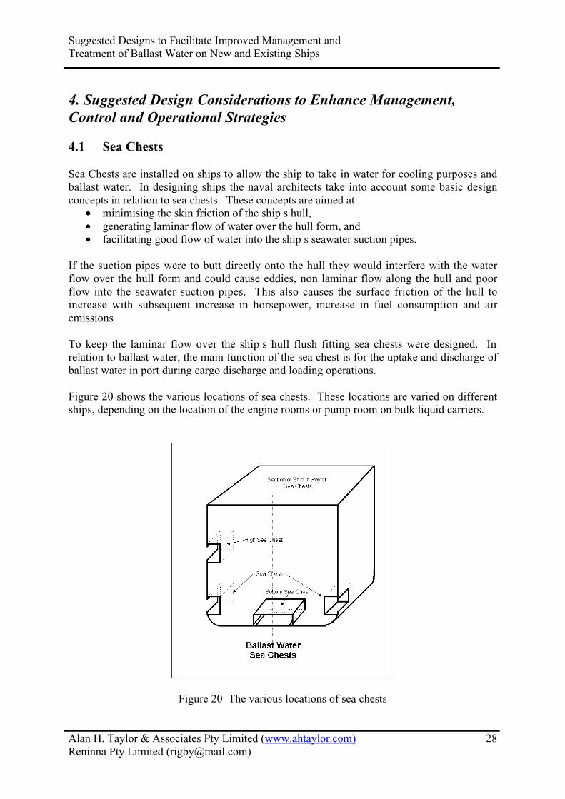
Suggested Designs to Facilitate Improved Management and
Treatment of Ballast Water on New and Existing Ships
Alan H. Taylor & Associates Pty Limited (www.ahtaylor.com)
Reninna Pty Limited ([email protected])
28
4. Suggested Design Considerations to Enhance Management,Control and Operational Strategies
4.1 Sea Chests
Sea Chests are installed on ships to allow the ship to take in water for cooling purposes and
ballast water. In designing ships the naval architects take into account some basic design
concepts in relation to sea chests. These concepts are aimed at:
• minimising the skin friction of the ship s hull,
• generating laminar flow of water over the hull form, and
• facilitating good flow of water into the ship s seawater suction pipes.
If the suction pipes were to butt directly onto the hull they would interfere with the water
flow over the hull form and could cause eddies, non laminar flow along the hull and poor
flow into the seawater suction pipes. This also causes the surface friction of the hull to
increase with subsequent increase in horsepower, increase in fuel consumption and air
emissions
To keep the laminar flow over the ship s hull flush fitting sea chests were designed. In
relation to ballast water, the main function of the sea chest is for the uptake and discharge of
ballast water in port during cargo discharge and loading operations.
Figure 20 shows the various locations of sea chests. These locations are varied on different
ships, depending on the location of the engine rooms or pump room on bulk liquid carriers.
Figure 20 The various locations of sea chests

Suggested Designs to Facilitate Improved Management and
Treatment of Ballast Water on New and Existing Ships
Alan H. Taylor & Associates Pty Limited (www.ahtaylor.com)
Reninna Pty Limited ([email protected])
29
4.1.1 Sea chest grate design
Sea chests are designed with flush fitting gratings installed in the openings of the ship s hull
to prevent large foreign matter entering the suction pipes and blocking up or damaging the
pumps and valves within the ship as well as preventing foreign matter accumulating in the
ship s ballast tanks. The sea chest gratings are therefore the primary filters in the pumping
and piping systems of the ship. In the case of ballast water and unwanted aquatic organisms
they also act as the primary filters removing the larger marine organisms. The size of the
grate openings are dependent on the actual size of the sea chest opening, the number of
suction pipes attached to the chest and the capacity of the pumps drawing water from the sea
chest. The flow of water required plus the blockage factor will determine the sizes of the
openings in the grate. In figure 21 it can be seen that this sea chest design has a hinged grate
with the hinges attached to the forward side of the grate and the grate is secured in position
by set screws or bolts.
The suggested design concept relating to sea chests is to install hinges on the forward sidein case the securing arrangements fail as many sea grates have fallen off in service. Byhinging them on the forward side the grate will not be lost, if it does come open it willfeather against the hull and can be readily re-secured, thereby keeping intact the primaryfilter in the ballast system.
Figure 21 Basic Design of Sea Chests

Suggested Designs to Facilitate Improved Management and
Treatment of Ballast Water on New and Existing Ships
Alan H. Taylor & Associates Pty Limited (www.ahtaylor.com)
Reninna Pty Limited ([email protected])
30
4.1.2 Sea chest design
It will be noted in figure 21 that sea chests are box like structure attached to the inner side of
the hull of a ship.
Sea chests are also fitted with air holes at the top and drain holes at the bottom through the
ship s hull. This ensures that there is no air trapped inside the chest when in service and at
dry dockings the water drains out of the sea chest. The valve connections to the sea chest are
located on the inside in the engine rooms or pump rooms and isolating valves are fitted on
each pipe connection to ensure the integrity of the ships hull in case of an emergency or pipe
failure within the hull of the ship.
The suggested design concepts are to:make the opening in the grate as small as possible to filter out larger marine organisms,and install hinges on the forward side in case the securing arrangements fail, as manygrates have been lost in service. By fitting hinges in the forward side of the grate it will notbe lost as the grate will feather against the hull and can be readily re-secured, therebykeeping intact the primary filter in the ballast system.
4.1.3 Air and Steam Connections
Figure 21 shows steam and air connections to the top of the sea chest. These are to blow
out the boxes to clear foreign matter from the grate if the ship or ballast system is starved for
water.
The suggested design concept is to fit a steam connection to all sea chests whereby thechest can be steamed out before and after ballasting in an endeavor to minimise the risk ofunwanted organisms becoming attached to the internal surfaces of the sea chest or takingup residence.
The steam would only have a minimal affect on the temperature of the water in the sea chest,
however the agitation, the imploding of the steam as it condenses and the heat imparted to the
water in the chest may be sufficient to kill some of the organisms or make others migrate
from the agitated and hostile environment.
Another suggested design concept for tankers fitted with a Butterworth Tank WashingSystem (for cargo tank washing) is for the hot water outlet from the Butterworth waterheaters to be connected to the sea chest and run hot water through the chest before andafter ballast operations. This could be accomplished by fitting an extra valve on to the seabox with a pipe connection to the Butterworth water heater outlet.
This procedure would also minimise the risk of unwanted organisms living in the sea chests
or others becoming attached to the internal surfaces.

Suggested Designs to Facilitate Improved Management and
Treatment of Ballast Water on New and Existing Ships
Alan H. Taylor & Associates Pty Limited (www.ahtaylor.com)
Reninna Pty Limited ([email protected])
31
4.1.4 Painting of sea chests
It is recommended during dry dockings that the internals of the sea chests, the grate and the
internals of the sea valves attached to the chests should all be painted with antifouling paint to
the same specifications as the hull of the ship, so that the biocide leaches minimising the risk
of unwanted organisms becoming attached to the internal surfaces of the sea chests.
4.1.5 Maintenance
The sea chests should be inspected in service by divers to ensure the gratings are attached and
intact, the internal surfaces are free from bio fouling and the chests are in good order and
condition. At dry dockings the gratings should be opened out, the internal surfaces cleaned,
inspected and repainted.
4.1.6 Operational Procedures
At the completion of ballast water operations the ballast water sea suction valves should be
shut, so as to ensure that ballast water piping is isolated from the outside water and the valves
are maintained in operational order. Prior to any ballasting operation, before opening the
ballast water sea suction valve, the box should be steamed out and if no steam connection is
available then it should be air blown. As previously mentioned, if the ship has a Butterworth
washing system installed, the sea chest could be washed out with hot water thereby ensuring
that some or all of unwanted organisms are killed or washed out. To undertake this washing
operation it would require a connection to be fitted to the sea chests.
4.2 Ballast System Design
4.2.1 Design
The ballast system in modern ships is usually designed for remote operation from a ballast
water control console located in the engine room, in a ballast water control room located
within the accommodation block or a control console on the bridge of the ship. These
developments have been mainly due to the number of crew members being reduced over the
years. The control room is usually co-located with other control areas such as the main
engine control room, the cargo control room on bulk crude carriers or in a dedicated area on
the bridge.
The ballast water system within the engine room is usually designed with dual ballast water
pumps, however in some systems there are three pumps to get the discharge capacity to
match the loading of cargo, as in the case of some LNG Carriers. In the Great Lakes, the
1000 footers , Bulk Carriers have up to 32 ballast pumps to match the 32 loading heads and
with Very Large Crude Oil Carriers (VLCC) or Ultra Large Crude Carriers (ULCC) ballast
water discharge capacities can be up to 20,000 m3/h. In the case of Cape Size Bulk Carrier
they can be fitted with 2 or 3 ballast water pumps with capacities of 2,000 to 3,000 m3/h.
These capacities are usually designed to match the time taken to load cargo at various
terminals, so that the ballast water can be discharged and stripped out ahead of the finishing
time of loading.

Suggested Designs to Facilitate Improved Management and
Treatment of Ballast Water on New and Existing Ships
Alan H. Taylor & Associates Pty Limited (www.ahtaylor.com)
Reninna Pty Limited ([email protected])
32
A 4,000 TEU Container vessels can have 2 to 3 ballast water pumps with capacities of around
550 m3/h. Container vessels and passenger ships do not usually load or discharge all of their
ballast water at one time, they only discharge or load ballast water to match the differentials
in cargo loading, to keep the ship upright or to obtain the correct draft and trim. To avoid
erosion of the internals of the ballast pumping and piping systems the ballast water velocity is
usually designed for a maximum of 3 m/s.
Ballast water pipes and piping manifolds are usually constructed within the engine room
using galvanized steel piping (usually rubber lined or lined with synthetic material) or other
non-corrosive piping. For many years ballast water mains (ring main) located outside
machinery spaces have been using Glass Reinforced Plastic (GRP) pipe in lieu of galvanized
steel pipe.
The ballast water pumps can either be fitted with self priming pumps or with a centralised
priming system or fitted with priming tanks. Figure 22 shows a system fitted to a Container
Ship with two priming tanks.
The ballast system is usually designed with a ring main with connections to each ballast tank
as can be seen in figure 24. Shutting the centre line crossover valves forward and aft in the
ring main can usually isolate the port and starboard side of the ring main. This design allows
selected tanks on one side to be filled whilst selected tanks on the other side can be emptied.
The ballast system is fitted with cross over valves adjacent to the ballast pumps that allow the
ballast water to flow in either direction, filling or discharging of the ballast water via gravity
and/or pumping.
Figure 22 Layout of ballast water system within the engine room of a container vessel
4.2.2 Ballast Water Suction Piping
It is suggested that all ballast water piping within the engine room be non-corrosive material,
however, because of the fire potential within the engine room, all piping installed within this
space should be fire resistant as required by the Administration and Classification Societies.

Suggested Designs to Facilitate Improved Management and
Treatment of Ballast Water on New and Existing Ships
Alan H. Taylor & Associates Pty Limited (www.ahtaylor.com)
Reninna Pty Limited ([email protected])
33
4.2.3 Hypo-chlorinators (electrolysis of sea water /chlorine)
It is suggested that the ballast water sea suction piping is fitted with a chlorine injection
system. This system consists of a chlorine generator wherein chlorine is manufactured by the
electrolysis of salt water. Chlorine is injected into the ballast suction piping in specific
quantities to assist in minimising bio fouling that may occur on the inside of the ballast water
piping. The sizing of the units will depend on the capacity of the ballast system, the velocity
of the water within the pipes and the dose rate recommended for treatment of the organisms
likely to cause bio fouling.
If such a system is installed then it is recommended that rubber or synthetic lined ballast
piping be used or a suitable type of material that will resist chlorine corrosion.
4.2.4 Operational procedures
The Hypo-chlorinator should be maintained in good condition and operated as required as
laid down in the manufacturers instructions. This will minimise build up of bio fouling
within the ballast water piping
4.2.5 Maintenance
All piping internals should be checked at each dry docking, as far as possible, to ensure that
the internal surfaces are free of bio fouling. If the piping has a build up this should be
removed and disposed of under environmental requirements as outlined by the appropriate
authority where the maintenance work is being done.
4.3 Ballast Water Valves
4.3.1 Ballast Valve Design
Valves within the ballast system are usually screw lift valves, butterfly valves or gate valves
depending on the requirements of owners or the shipyard standard to meet the requirements
of the vessel. Many valves within the ballast system are remote controlled and all should be
fitted with local indicators to show whether the valve is open or shut. This will aid the visual
safety inspection for isolation of ballast water tanks and the internal piping from the outside
water to stop contamination by unwanted organisms.
4.3.2 Operational procedures
All valves within the ballast water system should be shut and checked that they are closed
after ballasting operations. This is recommended to minimise cross contamination between
ballast water tanks, especially if the ballast water has been treated selectively or the ballast
water has been loaded in different ports.
Continuously shutting all ballast valves will ensure their operation and tightness when closed.
This will facilitate the internal cleaning of the ballast water strainers and the shutting out of
unwanted organisms when the system is not in use.

Suggested Designs to Facilitate Improved Management and
Treatment of Ballast Water on New and Existing Ships
Alan H. Taylor & Associates Pty Limited (www.ahtaylor.com)
Reninna Pty Limited ([email protected])
34
4.3.3 Maintenance
At dry dock it is recommended that all shipside valves and main valves be opened out and
overhauled, repaired and surveyed if required to ensure their correct operation and tightness.
It is recommended that all ship s side suction valves be opened up at each dry-dock and the
internals of the valves cleaned and painted with anti fouling paint to minimise bio fouling.
4.4 Sea Suction Strainers
4.4.1 Design and Material
Sea suction strainers are installed between the ship s side isolating valve and the ballast
pumps and acts as the secondary filter in the ballast water pumping and piping system.
Figure 23 shows a suction strainer. It original intention was to catch smaller objects before
entering the ballast water pumps to prevent blockage or damage to the centrifugal or
reciprocating pumps. These strainers also catch smaller organisms that have passed through
the sea grates on the sea chests.
The design recommendation for ballast water strainers is for the mesh or hole size of the
strainers to be designed as small as possible without restricting the water flow to the pumps
thereby catching more organisms before entering the ballast water system.
It is recommended that sea suction strainers be manufactured from stainless steel, preferably
SUS 316L. This recommendation is made to ensure that the strainers do not corrode in
service and lose their effectiveness as secondary filters. When they become full of organisms
or foreign matter the water flow to the ballast pumps could be restricted and this will
necessitate the cleaning out of the strainers.
Figure 23 Ballast water sea suction strainer
Suggested Designs to Facilitate Improved Management and
Treatment of Ballast Water on New and Existing Ships
Alan H. Taylor & Associates Pty Limited (www.ahtaylor.com)
Reninna Pty Limited ([email protected])
35
4.4.2 Operational procedures
Sea suction strainers should be cleaned before any ballasting operation. Opening up of the
strainers will allow a visual inspection on the inside of the adjacent ballast water pipes for the
presence of bio fouling and will also verify that the isolating valves are secure.
4.4.3 Maintenance
The sea suction strainers should be inspected every time they are cleaned. Any sign of
damage should be repaired to ensure that the second line of preliminary filtration is intact and
operational. It is recommended that a spare of each size of sea suction strainer basket be
carried on board.
The suggested design concept is to minimise larger marine organisms entering the vessel,so it is recommended that the sea chest and strainer mesh size be designed with thisintention in mind, however, they should be designed so as not to starve the ballast waterpumps of water.
4.5 Ballast Water Pumps
4.5.1 Types of ballast water pumps
There are two basic types of ballast water pumps, centrifugal and reciprocating. The
reciprocation pumps are usually direct displacement pumps and these can be somewhat
dangerous in ballast water systems as they can quickly over pressurise ballast water piping or
tanks if all the required valves are not opened correctly.
Ships are mainly installed with centrifugal pumps, as they will not achieve the hydraulic
pressure of reciprocating or other direct displacement pumps.
With centrifugal pumps the higher the head the more the pumps will cavitate until a state of
equilibrium is reached.
There are no special recommendations in the design of ballast pumps relating to unwanted
organisms or pathogens, except that they should be matched to the ballast water system to
achieve the best possible ballast water discharge in relation to cargo loading or discharge and
be sized to accommodate any additional requirements of treatment equipment as outlined in
section 3.

Suggested Designs to Facilitate Improved Management and
Treatment of Ballast Water on New and Existing Ships
Alan H. Taylor & Associates Pty Limited (www.ahtaylor.com)
Reninna Pty Limited ([email protected])
36
4.5.2 Operational procedures
To minimize the effect on the environment, good operational procedures should be followed
in the operation of ballast water pumps. Maximum use of gravity filling and discharging is
encouraged to enhance Sustainable Development and prevent air pollution by the
minimisation of the consumption of fuel oil.
When using centrifugal pumps it does not mean that the pumps can be left running at full rate
when a tank is full, as ballast water tanks are usually designed to withstand 1.25 times the
pressure head of the tank. If this pressure rating is exceeded, due to a restriction in the air
outlet, then the tank may be blown . The inverse of this can happen with reciprocating and
centrifugal pumps when the tanks are pumped out. If there is a restriction within the air pipes
then there could be an implosion of the tank/s. Both of these scenarios can seriously
damage the structural strength of a ship.
In developing the ballast water plan, the inverse of the cargo plan, it is recommended that
tanks only be filled to a designated level using two or more pumps and when this level is
reached the pump capacity should be reduced until one pump is used to finally fill or top off
the tank.
4.5.3 Maintenance
Ballast water pumps should be kept in good condition so as to ensure that the discharge
ballast water rate is sufficient to complete the ballast operations before the cargo loading is
completed. Good condition pumps will enhance the removal of ballast water and sediments
in port and also when exchanging ballast water at sea or in contingency areas thereby
minimising the operational time and the possible delay to the ship in a contingency situation.
4.5.4 Stripping Pumps
4.5.4.1 Types of Pumps
There are three main types of stripping pumps, centrifugal, direct displacement and eductors.
We have already mentioned two of these pumps above, centrifugal and direct displacement
(reciprocation).
The pump that is recommended for ballast water stripping operations is the eductor, as it has
no moving parts and because of the vacuum it generates it will easily regain the lost suction,
so the ballast water will be removed to the greatest extent possible.
The eductor is shown in figure 22, 24 & 25. Two suction heads are installed in each tank in
figure 25 to aid the discharge of the ballast water and sediment.

Suggested Designs to Facilitate Improved Management and
Treatment of Ballast Water on New and Existing Ships
Alan H. Taylor & Associates Pty Limited (www.ahtaylor.com)
Reninna Pty Limited ([email protected])
37
4.5.5 Operational procedures
The eductor should be started as soon as the main ballast pump/s begin to lose suction.
Figure 24 Iron Whyalla ballast water system in engine room and No. 9 hold

Suggested Designs to Facilitate Improved Management and
Treatment of Ballast Water on New and Existing Ships
Alan H. Taylor & Associates Pty Limited (www.ahtaylor.com)
Reninna Pty Limited ([email protected])
38
Figure 25 Iron Whyalla location of ballast water and eductor suction pipes
To obtain maximum discharge of ballast water in each tank the ship should be listed port and
starboard, port to empty the starboard tanks and starboard for the port tanks. In addition the
ship should be loaded so that it remains trimmed by the stern until the tanks have been
stripped by the eductor, listing port and starboard as described above
.
If the cargo plan/ballast water discharge plans in done correctly then minimum amounts of
ballast water should remain in the tanks. Once the ballast water is discharged the final
loading of cargo can take place to get the ship to the loaded draft and trim.
4.5.6 Maintenance
There is very little maintenance required with the eductor except for checking for corrosion
and erosion.
At each dry dock or special survey the suction heads should be checked for blockage,
corrosion or erosion.
4.6 Ballast Tanks
4.6.1 Design Recommendations to enhance ballast water and sediment removal andrefilling during Sequential Exchange

Suggested Designs to Facilitate Improved Management and
Treatment of Ballast Water on New and Existing Ships
Alan H. Taylor & Associates Pty Limited (www.ahtaylor.com)
Reninna Pty Limited ([email protected])
39
4.6.1.1 Water and sediment removal
Most double bottom tanks in ships are fitted with longitudinals, intercostals and floors which
give the double bottom of ships their structural strength. Some ships, such as older oil
tankers, were not fitted with double bottoms, however, these are in the main, being phased
out. The recommendations relating to double bottom tanks are that the inner bottom
longitudinal beams, where fitted, have extra drain holes along their length as shown in figure
26 which will allow the water to flow transversely across the ship to the ballast water and
stripping suction heads. Where the longitudinals butt up against a watertight bulkhead the
end of the longitudinal should be scalloped out as also shown in figure 26 to allow for the
water and sediment to drain away and not cause stagnant pools.
It will also be noted that the side longitudinals are fitted with their face bar stiffeners located
on the lower side of the longitudinals so as not to trap sediments and other particles if the face
bar stiffeners were place on the upper side of the longitudinals.
Figure 26 Extra drain holes and scallop holes in longitudinals and location of faceplate
stiffeners
Where double bottom tanks are fitted with intercostals between the floors, the floors should
be fitted with larger drain holes at the intersection of the intercostals and floors as shown in
figure 27. This has a double advantage of allowing better access for welding during
construction and better flow of water and sediment to the suction heads. Similar scallops
should be fitted at the joins of the inner bottom longitudinals or intercostals and floors to
allow for good air flow. The inner bottom longitudinal should also have similar holes to the
bottom longitudinals as shown in figure 26, as this will allow air to transit the longitudinals to
the air pipe insuring that minimum air is trapped within the tank during filling.

Suggested Designs to Facilitate Improved Management and
Treatment of Ballast Water on New and Existing Ships
Alan H. Taylor & Associates Pty Limited (www.ahtaylor.com)
Reninna Pty Limited ([email protected])
40
Figure 27 Location of Larger Drain Holes at Junction Intercostals & Floors
Figure 28 shows in diagrammatic form the design concept. The drawing is a transverse
section through the ship that shows all the air and drain holes, the reversed face flat bar
stiffeners on the longitudinals, the ballast water suction and filling heads and the stripping
suction heads. This sketch show a good design of a Bulk Carrier that will assist the flow of
water to the suction heads and will minimise the sediment retention in the ballast tanks.
When designing a ship it is recommended to request the shipyard to design the best water
flow (by CFD) to the suction heads and also the internal structure to minimise sediment
hang up .
When ballast water exchange pump out and refill, sequential method is used this design
concept will maximise the removal of port water and sediment that has been taken on board
at the ballast uptake port.
In addition the international requirements of the Enhanced Survey for Tankers and Bulkers,
require all ballast water tanks to be internally coated to minimise corrosion. This requirement
will also minimise sediment retention as it will minimise rust accumulation.

Suggested Designs to Facilitate Improved Management and
Treatment of Ballast Water on New and Existing Ships
Alan H. Taylor & Associates Pty Limited (www.ahtaylor.com)
Reninna Pty Limited ([email protected])
41
Figure 28 Transverse section of a bulk carrier
For ships fitted with side tanks that have the tank bottom as part of the bottom of the ship,
then the girder and longitudinal design concept of enlarging the drain holes is similar to that
described above for the lower side tanks of the Bulk Carrier. Many Handy Size Bulk
Carriers, Tankers, Container Vessels and LNG Carriers have side ballast tanks, so this design
concept is good for nearly all ballast water tanks.
To assist with the pumping out of ballast water it is recommended that the drain and air holes
as described be designed into the ship at build.
The suggested design concepts are:• install additional drain holes in longitudinals and intercostals,• install larger drain holes in floors at intersection of longitudinals and intercostals,
and• Install larger drain holes in horizontal and vertical longitudinals, corner gussets,
panting stringers and intercostals where they butt up against watertight bulkheadsto stop hang up of sediment and particles.
This will allow better flow into the ballast water suction and stripping heads located in thelast aft bays of tanks. Naval Architects should undertake flow calculation (CFD) todetermine the size of the drain holes to confirm that there is sufficient flow of water to thesuction heads to match the capacity of the discharge of the ballast system. This will ensurethat the maximum amount of water and sediment is discharged with minimum hang upof sediment within the tanks.

Suggested Designs to Facilitate Improved Management and
Treatment of Ballast Water on New and Existing Ships
Alan H. Taylor & Associates Pty Limited (www.ahtaylor.com)
Reninna Pty Limited ([email protected])
42
4.6.1.2 Additional design concepts to assist in ballast water removal
In ships such as Container Ships, LNG Carriers, Passenger Ships and ships that have ballast
tanks that do not form part of the bottom of the ship, there is the capacity of installing hat
boxes for the ballast water suction heads (figure 29).
Figure 29 Showing design of Hat Box in Tank
In the case of ballast holds in large Bulk Carriers where the bottom of the tank is in fact the
inner bottom of the ship, figure 30 shows this design concept for the suction head. This is
quite a good design as it traps the silt and rubbish in the front side of the weir as well as
maximizing the ballast water discharged.

Suggested Designs to Facilitate Improved Management and
Treatment of Ballast Water on New and Existing Ships
Alan H. Taylor & Associates Pty Limited (www.ahtaylor.com)
Reninna Pty Limited ([email protected])
43
Figure 30 Showing ballast hold hat box design with weir
The suggested design enhancement is for hat Box suctions to be installed in tanks wherepossible.
4.6.1.3 Design of tanks to enhanced Access for cleaning and maintenance
Figure 31 also shows access for cleaning and maintenance on a Bulk Carrier s ballast tanks at
sea. Similar access arrangements are suitable for Ore and Oil Carriers and ships that have
ballast side tanks. Ships which have double bottom tanks, without side tanks or transverse
bulkhead stools, usually cannot be accessed at sea when there is no ballast water on board as
the cargo usually covers the double bottom manhole access lids. Figure 31 also show access
to the double bottom tank via a manhole located in the duct keel.
The suggested design enhancement is that safe access to all ballast water tanks be takeninto consideration for all ships at the design stage.

Suggested Designs to Facilitate Improved Management and
Treatment of Ballast Water on New and Existing Ships
Alan H. Taylor & Associates Pty Limited (www.ahtaylor.com)
Reninna Pty Limited ([email protected])
44
Figure 31 Enhanced access and sampling tubes on a bulk Carrier
4.6.2 Operational Procedures
4.6.2.1 During uptake of Ballast Water
o All the precautionary practices outlined in section 2 should be implemented
where safe and practical to do so.
o As the ballast water operation is considered a Critical Process full
operational procedures should be prepared and approved under the ISM Code.
o All aspects of the Ballast Water Management Plan relating to uptake of ballast
water should be adhered to.
o Care should be taken to plan the ballast operation together with the Cargo Plan
and if the cargo plan changes then the ballast plan should be reviewed to take
account of any changes.
o The safety checklist should be adhered to and all items on the checklist should
be physically checked prior to operations
o If high ballast water suctions are installed the suction with maximum bottom
clearance should be used.
o Ballast Water Sea Chest should be blown through .
o Sea Suction Strainers should be checked and cleaned.

Suggested Designs to Facilitate Improved Management and
Treatment of Ballast Water on New and Existing Ships
Alan H. Taylor & Associates Pty Limited (www.ahtaylor.com)
Reninna Pty Limited ([email protected])
45
o Minimum ballast water should be loaded at the berth and if possible ballast
down to full ballast draft in deeper cleaner water.
o Ballast water should be gravity fed as much as possible to reduce air emissions
and conserve fuel.
o Care should be taken when filling tanks that two pumps are not used on one
tank to top off.
o Within the ballast plan a clear first maximum level should be designated to
ensure that reduced rate of filling is used to top off the ballast tank.
o Full records of the ballast operation should be kept as per the requirements of
the BWMP.
4.6.2.2 During uptake for ballast water exchange, sequential method
o All of the aforementioned procedures as outlined in 4.6.2.1 should be adhered
to except the precautionary practice relating to in port uptake of ballast
water.
o In addition to these requirements, ballast water should only be taken on board
in deep ocean water in Ballast Water uptake areas.
o Full records of the ballast operation should be kept as per the requirements of
the BWMP.
4.6.2.3 During flow through exchange
o As the ballast water operation is considered a Critical Process full
operational procedures should be prepared and approved under the ISM Code.
o All aspects of the Ballast Water Management Plan relating to the flow
through method of ballast water exchange should be adhered to.
o Care should be taken to plan the ballast operation. If any changes occur then
the ballast plan should be reviewed to take account of these changes.
o The safety checklist should be adhered to and all items on the checklist should
be physically checked prior to operations.
o Ballast Water Sea Chest should be blown through .
o Sea Suction Strainers should be checked and cleaned.
o The overflow system should be checked to ensure no obstructions and all
valves, lids and overflow mechanisms open.

Suggested Designs to Facilitate Improved Management and
Treatment of Ballast Water on New and Existing Ships
Alan H. Taylor & Associates Pty Limited (www.ahtaylor.com)
Reninna Pty Limited ([email protected])
46
o Flow through ballast capacity should not be exceeded during the flow through
operation.
o Three tank volumes should be exchanged.
o Full records of the ballast operation should be kept as per the requirements of
the BWMP.
4.6.3 Maintenance of tanks
4.6.3.1 In service
All ballast tanks should be inspected in service for breakdown of paint and sediment
accumulation.
4.6.3.2.1 Painting
As required by the new international regulations relating to the enhanced survey of tankers
and bulkers, ballast water tanks should be painted to prevent corrosion. During inspections
the paint should be inspected for breakdown and rust formation. If paint has broken down
and rust scale is forming it should be noted for attention at the next repair period or dry
docking. If the painted surfaces are not repaired then the rust scale will accumulate in the
bottom of the ballast tanks and will trap sediment with the possibility of unwanted aquatic
organisms (including dinoflagellate cysts).
4.6.3.2.2 Sediment removal
If sediment starts to accumulate in ballast water tanks and if positive samples taken by the
appropriate regulatory authority identify unwanted aquatic organisms, the ship staff may be
requested to clean and remove the accumulated sediment. This is a very difficult, dangerous
and time consuming operation at sea.
In addition some ballast tanks can only be entered when a ship is taken out of service as when
loaded the manhole access covers are under the cargo and when the ship is in ballast they
cannot be entered, therefore it makes sediment removal very difficult.
4.6.3.2 In Dry Dock
At each dry dock of the vessel it is recommended that the internals of the ballast water tanks
be inspected to determine the condition of the paint and the accumulation of sediment.
4.6.3.2.1 Painting
If there is breakdown of the protective paint system, it should be repaired.
4.6.3.2.2 Sediment removal
If there is any sediment and rust accumulation it should be removed and the tanks flushed out
to a clean condition. If there is excessive accumulation of sediment and scale it may be
expedient to cut access holes in the bottom of the ship to aid its removal.

Suggested Designs to Facilitate Improved Management and
Treatment of Ballast Water on New and Existing Ships
Alan H. Taylor & Associates Pty Limited (www.ahtaylor.com)
Reninna Pty Limited ([email protected])
47
Any sediment removal should be disposed of under environmentally acceptable conditions as
approved by the appropriate authority.

Suggested Designs to Facilitate Improved Management and
Treatment of Ballast Water on New and Existing Ships
Alan H. Taylor & Associates Pty Limited (www.ahtaylor.com)
Reninna Pty Limited ([email protected])
48
5. Ship design consideration for minimising sediment containedin ballast water.
5.1 During uptake of ballast water
During uptake of ballast water uptake of sediments is possible if the ballast water sea chest is
too close to the bottom at the berth, if dredging operations are being undertaken in the
vicinity, or the propeller has stirred up the bottom sediment.
The precautionary practices make mention of some of these conditions, however there is one
design enhancement to help overcome the scouring of the bottom sediment into the ballast
system, that is by installing high sea suctions into new tonnage as shown in figure 32
.
It is recommended that the lower edge of the sea chest should be greater than 5 metres from
the bottom at the berth. If the clearance is less than 5 metres it is recommended that the high
sea suctions be used.
Figure 32 Suggested operations procedures for high sea suctions
The suggested design enhancement is to install high sea chest on board new ships.
5.2 During voyage
There are many operational procedures that can be employed to remove sediment for ballast
tanks during a loaded voyage.
5.2.1 Washing out of ballast tanks
Ballast tanks can be manually washed out, however, this is quite a dangerous job and very
time consuming. The Butterworth Tank Washing System is a very good and proven method
which could be suitable for Bulk Ore and Oil Carriers.

Suggested Designs to Facilitate Improved Management and
Treatment of Ballast Water on New and Existing Ships
Alan H. Taylor & Associates Pty Limited (www.ahtaylor.com)
Reninna Pty Limited ([email protected])
49
This system was first developed for washing out cargo tanks on Bulk Oil Carriers. It consists
of a portable high speed washing head that can be lowered into the tanks through a standard
deck fitting (like a small manhole opening).
The washing heads are designed to spray tangential jets of water from a rotating head whilst
sets of gears rotate the head horizontally through 360 degrees. The spray heads can be
lowered into the tanks and set at different levels to obtain full washing of the tanks. This
system will wash down hung up sediment deposits which can then be stripped out by the
stripping system. The effectiveness of this washing system will be enhanced by installation
of the previously mentioned enhanced design aspects for the internals of ballast tanks.
Butterworth Tank Washing systems can also be fitted to existing tonnage.
The suggested design enhancement is to consider fitting Butterworth Tank WashingSystems to suitable New and Existing Tonnage.
Figure 33 Butterworth Tank Washing System
5.2.2 De flocculating chemical
De flocculating chemicals are available to re-suspend sediment back into solution as an aid to
removing sediment from ballast tanks. These chemicals should be used in an
environmentally acceptable manner.
5.2.3 Sloshing effect
To assist in the removal of sediment it is suggested that the tanks are partially filled, if
stability and other limitation relating to the strength of the ship are not exceeded, and the
water is allowed to slosh around in a sea way and then stripped out in an acceptable location.

Suggested Designs to Facilitate Improved Management and
Treatment of Ballast Water on New and Existing Ships
Alan H. Taylor & Associates Pty Limited (www.ahtaylor.com)
Reninna Pty Limited ([email protected])
50
5.2.4 Heating and sloshing
An added effect can be obtained if hot water from the main engine cooling system is used as
the sloshing water as described in section 3.2. This will give a double effect to this
recommended procedure.
5.2.5 Manual removal
This is described in section 4.6.6.1.2 and as shown in figure 31.
In addition to the tanker type access, trunk connection from the upper wing tanks to the lower
wing tanks and the common lower side tank and double bottom tank as in figure 31, the
design also shows a manhole access from the duct keel. Many of these access designs can be
use on all types of new ships, however some of them are very difficult to fit to existing ships.
If sediment removal is contemplated during a voyage, it is recommended that a portable
lifting device be designed to straddle the tanker type access hatch or manhole and various
lifting lugs be installed within the tanks to assist in the sediment removal.
The suggested design concept is for safe access to be provided to all ballast water tanks onall ships to allow for manual sediment removal and access for selective sediment sampling.
5.3 During Discharge
If the enhanced design concepts are installed as described in section 4.6.1 then there should
be good sediment removal with minimum retention of sediment in the tanks. This has been
demonstrated on the Iron Whyalla (Rigby et al., 1993). This ship was built with the design
enhancement of larger drain holes etc., as described in section 4.6 of this report and the
photographs within the report show the minimal amount of sediment in the ship s tanks. At
the time the photographs were taken the ship was 11 years old and minimum sediment
removal had been undertaken. (Taylor, private communication).
Suggested Designs to Facilitate Improved Management and
Treatment of Ballast Water on New and Existing Ships
Alan H. Taylor & Associates Pty Limited (www.ahtaylor.com)
Reninna Pty Limited ([email protected])
51
6. Ship Design considerations for minimising bottom sedimentother than contained in ballast water
The main sediment other than contained in ballast water is that which is attached to anchors
and anchor chains after the ship has anchored and retrieved its anchors. Ships are usually
fitted with washing facilities installed in the anchor pipes to hose down the cables and
anchors whilst they are being retrieved and stowed.
Inspection of chain lockers has shown that bottom sediment, in some instances, still adheres
to some of the chain links and anchors even after being washed. This sediment will usually
accumulate in the chain lockers unless removed.
If water leaks into the chain lockers via the spurling pipes in heavy weather it can cause the
cable to be covered with the accumulated sediment within the lockers.
6.1 Chain Lockers
When anchors are housed the chains are stowed in two lockers built under the forecastle head
of the ship.
6.1.1 Design
The design is usually two separate cylindrical lockers wherein the cables stack up as they
come off the gypsies via the spurling pipes as the anchors and cables are lifted. Water and
sediment drains off the cables and accumulates in the bottom of the lockers. Chain lockers
are usually designed with a bilge system to pump out this accumulated water and sediment.
6.1.2 Washing in service
As the cable and anchors are lifted, the cables and anchors are washed off by a fixed washing
system installed into the anchor pipes. It is not unusual for the anchors to be finally washed
off by a fire hose if the sediment accumulation is heavy.
6.1.3 Enhanced design of chain lockers and washing system
A suggested enhanced design for chain lockers is to install a grate at the bottom of thechain lockers that is raised approximately 0.5 of a metre above the bottom of the chainlocker with a manhole access to the space under the grate for cleaning out accumulatedsediment.
In addition it is suggested installing additional spray nozzles within the locker as shown in
figure 34. These additional washing nozzles should wash off the sediment that should fall
through the grate into the bilge area.

Suggested Designs to Facilitate Improved Management and
Treatment of Ballast Water on New and Existing Ships
Alan H. Taylor & Associates Pty Limited (www.ahtaylor.com)
Reninna Pty Limited ([email protected])
52
To remove this water and sediment it is recommended to install an eductor bilge system. To
further enhance this water and sediment removal the bottom of the locker can be fitted with a
hat box wherein the bilge suction head is installed. It is also recommended that a back
flushing system be installed into the bilge suction circuit to blow through the bilge suction
piping to keep the system clear.
The suggested design enhanced for Chain Lockers is to install extra washing nozzleswithin each chain locker, install a raised grate with sufficient height to allow cleaning outof this area via manhole access.
Figure 34 Suggested chain locker design
6.1.4 Operational procedures
It is recommended that when cables and anchors are raised the water washing system and the
eductor system be operated. This should ensure adequate cleaning of the cables and anchors.
Prior to entering port waters, preferably in deep ocean water, it is recommended that the
space under the anchor cables be inspected, cleaned and pumped out. It is also recommended
that the cables be inspected from the top manhole access to the chain lockers to ensure that
they are also clean. If there is still sign of sediments on the cables then it is recommended
that the cables be re-washed by the installed washing system and all sediment pumped
overboard.

Suggested Designs to Facilitate Improved Management and
Treatment of Ballast Water on New and Existing Ships
Alan H. Taylor & Associates Pty Limited (www.ahtaylor.com)
Reninna Pty Limited ([email protected])
53
6.1.5 Maintenance procedures
It is recommended that the washing system is kept in good working order and the hatbox is
kept clean of sediment after each washing operation.
At dry dock when the anchor cables are ranged for inspection it is recommended that the
chain lockers are cleaned, inspected and painted to prevent corrosion and rust formation that
can trap sediment in the bottom of the chain locker on top of the grate. It is also
recommended that the washing and bilges system is tested and proved to be in good working
order.

Suggested Designs to Facilitate Improved Management and
Treatment of Ballast Water on New and Existing Ships
Alan H. Taylor & Associates Pty Limited (www.ahtaylor.com)
Reninna Pty Limited ([email protected])
54
7. Discussion and conclusions
The adoption of any of the treatment and/or management options proposed, as part of the
IMO MEPC international instrument will require the retrofitting or modification of existing
pipework and/or equipment on existing ships to permit the new procedures to be put into
practice in a safe, technically effective, environmentally acceptable, practical and cost
effective way.
It will be possible to install and implement these new technologies and practices on new ships
much more readily since the appropriate modifications and new equipment can be considered
at the design phase. Provisions for the modification/installation of new and improved
treatment technologies as they are developed in the future can also be accommodated at the
design phase by allowing space within the engine room or other suitable areas. The costs
involved will represent a minor additional cost of the new ship. It is therefore important that
adequate consideration be given to these concepts at the new ship design stage.
An essential part of any effective system will be the Ballast Water Management Plan, which
will be required for every ship. It is important that the BWMP be considered as part of the
new ship design and that attention be given to ensure that appropriate communication and
compliance systems are installed to facilitate the management requirements. Its likely that no
single ballast water management or treatment technique will provide a universal solution for
use on all ships, consequently when developing the BWMP owners and the designers should
consider the range of options available and make use of the most appropriate option(s) for the
particular ship, based on voyage schedules and duration, ship operational requirements and
country/port requirements.
Sampling of ballast water and/or sediments from ships is an important part of ongoing
research, monitoring and compliance programmes. A range of design suggestions has been
included to facilitate more effective and representative sampling.
Ocean exchange of original ballast water, using one or more of the possible options
(including emptying and refilling, continuous flushing or the Brazilian Dilution Method)
forms the basis of ballast water control measures being utilised by several countries at present
and is likely to continue as a preferred option for the near future. A review of the various
options as well as a number of design suggestions aimed at providing flexibility and safety
and making provision for use of one or more options have been presented.
Although ocean exchange is currently the most widely accepted treatment option, the
generally accepted efficiency of water exchange (approximately 95% for continuous flushing
using three tank volumes, and higher for empty /refill) means that substantial numbers of
organisms are still present in the water discharged in the receiving port and may constitute a
serious threat to the receiving environment. These options currently give the best appropriate
level of protection currently available. The further development and adoption of new
technologies that are capable of higher efficiencies of removing or killing organisms will
form an essential part of future ballast water management practices.

Suggested Designs to Facilitate Improved Management and
Treatment of Ballast Water on New and Existing Ships
Alan H. Taylor & Associates Pty Limited (www.ahtaylor.com)
Reninna Pty Limited ([email protected])
55
Heating of ballast water using waste heat from the main engine cooling water system to kill
or inactivate a range of harmful organisms has been demonstrated to be both environmentally
attractive and cost effective in some cases, especially on international voyages of duration in
the vicinity of 10 days or longer. Relatively simple modifications to pipe work as well as
changes to the heating circuit involving some additional heat exchangers can extend the use
of this technique to a much wider range of ships and voyages. The potential for a high level
of biological effectiveness of this option means that it may well become one of the preferable
long term treatment technologies.
Although various chemicals can be quite effective in killing some organisms, it is likely that
costs, practical and safety considerations and undesirable environmental effects will limit
extensive use in ballast water treatment. However there may be some special circumstances
where chemicals might need to be used and appropriate design procedures to handle
chemicals in a shipboard environment have been suggested.
Several other treatment options, including filtration, hydrocyclones, ultraviolet irradiation
oxygen deprivation and electrical shock have been suggested and are being demonstrated in
some cases at practical alternatives. However at the current stage of development, only
preliminary performance data is available and equipment design criteria is somewhat limited.
However some typical design guidelines for filtration, hydrocyclones and ultraviolet
irradiation have been included as a basis for preliminary designs.
The potential for use of fresh or recirculated process water, as well as the discharge of ballast
water to shore based or a dedicated treatment ship facilities may be possible in some cases
and design aspects to facilitate the provision of shipboard infrastructure to facilitate the
handling and transfer of water have been discussed.
In addition to the design concepts associated with above treatment options, a wide variety of
practical design concepts associated with the movement and management of ballast water and
sediments have been developed from ship design and operational experience over many
years. It is important that this knowledge and experience be captured in new ship designs to
minimise the build up of sediments and to allow the range of management and treatment
options to be designed and utilised at the highest level of efficiencies.
In particular, best practice design aspects related to sea chests, ballast tanks (especially
strength, water flow and minimisation of sediment accumulation), ballast pumps and piping
and chain lockers in relation to removal of ballast water and sediment have been reviewed
and discussed in some detail to allow these concepts to be considered and implemented at the
design phase, where appropriate.
There are many design aspects associated with new ships that will enhance the ability to carry
out appropriate ballast water management and treatment. As an aid to identifying the most
practical and cost effective system(s) and developing the BWMP for a particular ship, it is
recommended that a New Ship Design Check List be developed as a basis for reviewing the
various options at the design phase. This List would contain suggested design features to be
considered for each aspect of management and treatment and would be best developed after
r ev i ew o f t he de s ign c r i t e r i a sugges t ed i n t h i s r epo r t .

Suggested Designs to Facilitate Improved Management and
Treatment of Ballast Water on New and Existing Ships
Alan H. Taylor & Associates Pty Limited (www.ahtaylor.com)
Reninna Pty Limited ([email protected])
56
8. References
AMBS. 1997. Ability of target species to survive in ballast water. Report prepared by
Australian Museum Business Services for the Australian Quarantine and Inspection Service.
168 pp.
Anderson, D.M., C.D. Taylor and E.V. Armburst. 1987. The effects of darkness and
anaerobiosis on dinoflagellate cyst germination. Limnology and oceanography 32(2): 340-
351.
Anon. 2000. Regal Princess becomes first ship to retrofit ballast water treatment plant.
Marine Engineers Review. July/August. 13-14.
AQIS, 1998. Australian ballast water management guidelines. Australian Quarantine and
Inspection Service.
Armstrong, G. 1997. Ballast system design for flow-through exchange of ballast water. Trans
IMarE. 109(3): 257-269.
Bolch, C.J. and G. M. Hallegraeff. 1993. Chemical and physical treatment options to kill
toxic dinoflagellate cysts in ships ballast water. J. Marine Env. Engg. (1):23-29.
Carlton, J.T. 1985. Transoceanic and interoceanic dispersal of coastal marine organisms: the
biology of ballast water. Oceanogr. Mar. Biol. Ann. Rev. 23, 313-374.
Carlton, J.T. 1990. Preventative options for the management and control of accidental and
intercontinental transfers of exotic organisms. Workshop on Exotic Species and the Shipping
Industry. Toronto. March 1-3. Issued by Int. Joint Comm.- Great Lakes Fish. Comm.
Carlton, J.T. and J.B. Geller. 1993. Ecological roulette: the global transport of non-
indigenous marine organisms. Science. 261 (5117):78-82.
Carlton, J.T., D. M. Reid and H. van Leeuwen. 1995. The role of shipping in the introduction
of non indigenous aquatic organisms to the coastal waters of the United States (other than the
Great Lakes) and an analysis of control options. National Sea Grant College Program/CT Sea
Grant Project R/ES6, 213pp.
EUCA (European Union Concerted Action). 2000. Testing monitoring systems for risk
assessment of harmful introductions by ships to European waters. Final Report. Contract No:
MAS3-0111.
Hallegraeff, G.M. and C. J. Bolch. 1992. Transport of dinoflagellate cysts in ship s ballast
water: implications for plankton biogeography and aquaculture. J Plankton Res. 14:1067-
1084.
Hallegraeff, G.M, J.P. Valentine, J.A. Marshall and C.J Bolch. 1997. Temperature tolerances
of toxic dinoflagellate cysts: application to the treatment of ships ballast water. Aquatic
Ecology 31:47-52.

Suggested Designs to Facilitate Improved Management and
Treatment of Ballast Water on New and Existing Ships
Alan H. Taylor & Associates Pty Limited (www.ahtaylor.com)
Reninna Pty Limited ([email protected])
57
Hay, C., S. Handley, T. Dodgshun. M. Taylor and W. Gibbs. 1997. Cawthron s ballast water
research programme final report 1996-97. Report prepared for Ministry of Agriculture, Sept.
139pp.
Hewitt, C.L. 2000. Baseline port sampling for introduced marine species. Paper presented at
Sea Australia Conf. Sydney, Aust. 1-3 Feb.
IMO MEPC 1996, International Maritime Organization, Marine Environmental Protection
Committee, Report 38/13/2 -Brazil.
IMO MEPC 2000, International Maritime Organization, Marine Environmental Protection
Committee, Harmful Aquatic Organisms in ballast water-Development of standards for
ballast water management and control options and their assessment and approval, MEPC
45/2, Submitted by Australia, 20 July.
Karaminas, L. 2000. An investigation of ballast water management methods with particular
emphasis on the risks of the sequential method. Lloyd s Register of Shipping, June, 19pp.
Montani, S., S. Meksumpun and K. Ichimi. 1995. Chemical and physical treatments for
destruction of phytoflagellate cysts. Journal of Marine Biotechnology. 2:179-181.
Mountfort, D.O. 1997. Ballast water treatment. Cawthron initiates a long-term solution to the
ballast water problem. Seafood New Zealand, July, 38-39.
NRC. National Research Council. 1996. Stemming the tide: controlling introductions of
nonindigenous species by ships ballast water. National Academy Press. Washington D.C.
152pp.
Oemcke, D. J. 1999. The treatment of ships ballast water. Ports Corporation of Queensland.
EcoPorts Monograph Series No. 18, March. 92pp.
Rigby, G.R., I. Steverson and G.M. Hallegraeff. 1993. Shipping ballast water trials on the
bulkcarrier M.V. Iron Whyalla. AQIS Ballast Water Research Series, Report No. 2. Sept.
123pp.
Rigby, G.R. 1994. Possible solutions to the ballast water problem, AQIS Ballast Water
Symposium Proceedings, Canberra 11-13 May.
Rigby, G.R. and G.M. Hallegraeff. 1994. The transfer and control of harmful marine
organisms in shipping ballast water: behavior of marine plankton and ballast water exchange
on the MV Iron Whyalla . J. Marine Env. Engg., 1: 91-110.
Rigby, G.R. and A.H. Taylor. 1994. Ocean exchange of ship s ballast water to minimise the
transfer of harmful marine organisms - a review of research work and recommendations for
the use of different options. BHP Research Tech. Rep. BHP/ENV/R/94/015. March.
Suggested Designs to Facilitate Improved Management and
Treatment of Ballast Water on New and Existing Ships
Alan H. Taylor & Associates Pty Limited (www.ahtaylor.com)
Reninna Pty Limited ([email protected])
58
Rigby, G.R. 1995. On board treatment and reballasting options. Proc. Symposium on Ballast
Water-A Marine Cocktail on the Move. Organised by The Royal Society of New Zealand.
Miscellaneous Series 30. Wellington New Zealand. June 27-29. 106-113.
Rigby, G.R., G.M. Hallegraeff, and C.A. Sutton. 1998. Novel ballast water heating and
sampling trials on the BHP ship MV Iron Whyalla. AQIS Ballast Water Research Series,
Report No.11. Oct.
Rigby, G.R., G.M. Hallegraeff, and C.A. Sutton. 1999 Novel ballast water heating technique
offers cost-effective treatment to reduce the risk of global transport of harmful marine
organisms. Mar. Ecol. Prog. Ser. 191:289-293.
Rigby, G.R. and A.H Taylor. 1999. Progress in the management and treatment of shipping
ballast water to minimise the risks of translocating harmful nonindigenous aquatic organisms.
Proc. National Conference on Marine Bioinvasions, MIT, Cambridge, MA, USA, 25-27 Jan.
Rigby, G.R. and A.H Taylor. 2000. Ballast water treatment to minimise the risks of
introducing nonindigenous marine organisms into Australian Ports-review of current
technologies and comparative indicative costs of practical options. Report prepared for AQIS
Research Advisory Group Ballast Water Research Programme, 93 pp.
Sobol, Z., K. Wladyslaw. and W Bohdan. 1995. System for destruction of microorganisms
occurring in ballast waters. Paper presented at IMO MEPC 38.
Sutton, C.A., K. Murphy, R.B. Martin and C.L Hewitt. 1998. A review and evaluation of
ballast water sampling protocols. Centre for Research on Introduced Marine Pests, CSIRO
Marine Research, Technical Report Number 18. 113 pp.
Taylor, A.H. 1996. Design considerations for ballast water controls and treatment. Proc.
Shipping and the Environment Symp. Organised by The Inst. Mar. Engrs. London 22-14
October.
Thornton, G. 2000. Ballast water decontamination-using heat as a biocide. Paper presented at
Sea Australia Conf. Sydney, Aust. 1-3 Feb.
Vinogradov M.E., E.A. Shushkina, E.I. Musayera and P.Y. Sorokin. 1989. A newly acclimated
species in the Black Sea: the ctenophore Mnemiopsis leidyi (Ctenophora: Lobata). Okeanol. 29
: 220-24.