substation interface unit n-8010rs - toa-products.com · substation interface unit n-8010rs thank...
TRANSCRIPT

INSTALLATION MANUAL
SUbSTATION INTerfAce UNIT N-8010rS
Thank you for purchasing TOA’s Substation Interface Unit.Please carefully follow the instructions in this manual to ensure long, trouble-free use of your equipment.

2
TAbLe Of cONTeNTS
1. SAfeTY PrecAUTIONS ............................................................................. 3
2. GeNerAL DeScrIPTION .......................................................................... 5
3. feATUreS ............................................................................................................ 5
4. NOMeNcLATUre AND fUNcTIONS ................................................. 6Front ............................................................................................................................. 6Rear ............................................................................................................................. 6
5. INSTALLATION .................................................................................................. 75.1. Equipment Rack Mounting .................................................................................... 7
5.1.1. Setting space ............................................................................................... 85.1.2. Caution when installing the unit .................................................................. 85.1.3. Mounting on the rack ................................................................................... 9
5.2. Desk-Top Installation ............................................................................................. 95.3. Wall Mounting ..................................................................................................... 10
6. WIrING .................................................................................................................. 116.1. Connection Diagram ............................................................................................ 116.2. Type of Cable ...................................................................................................... 136.3. Relations Between Core Diameter of Cable and Maximum Cable Length ......... 136.4. Removable Terminal Plug Connection ............................................................... 136.5. E-7000TB Terminal Board Wiring ....................................................................... 14
7. AcceSSOrIeS ................................................................................................. 15
8. OPTIONAL PrODUcT ................................................................................ 15

3
1. SAfeTY PrecAUTIONS• Before installationoruse,besure tocarefully readall the instructions in thissection forcorrectandsafe
operation.• Besuretofollowalltheprecautionaryinstructionsinthissection,whichcontainimportantwarningsand/or
cautions regarding safety.• Afterreading,keepthismanualhandyforfuturereference.
Safety Symbol and Message conventions Safety symbols and messages described below are used in this manual to prevent bodily injury and property damage which could result from mishandling. Before operating your product, read this manual first and understand the safety symbols and messages so you are thoroughly aware of the potential safety hazards.
Indicates a potentially hazardous situation which, if mishandled, could result in death or serious personal injury.
WArNING
When Installing the Unit• Donotexpose theunit to rainor anenvironment
where it may be splashed by water or other liquids, asdoingsomayresultinfireorelectricshock.
• Use the unit only with the voltage specified onthe unit. Using a voltage higher than that which is specifiedmayresultinfireorelectricshock.
• Do not cut, kink, otherwise damage nor modifythe power supply cord. In addition, avoid using the power cord in close proximity to heaters, and never place heavy objects -- including the unit itself -- on the power cord, as doing somay result in fire orelectric shock.
• Avoid installing or mounting the unit in unstablelocations, such as on a rickety table or a slanted surface. Doing so may result in the unit falling downandcausingpersonal injuryand/orpropertydamage.
• Installtheunitonlyinalocationthatcanstructurallysupport the weight of the unit and the mounting bracket. Doing otherwise may result in the unit falling down and causing personal injury and/orproperty damage.
When the Unit is in Use• Should the following irregularity be found during
use, immediately disconnect the power supply plug from the AC outlet and contact your nearest TOA dealer. Make no further attempt to operate the unit in thisconditionas thismaycausefireorelectricshock.· If you detect smoke or a strange smell coming
from the unit· If water or any metallic object gets into the unit · If the power supply cord is damaged (exposure of
the core, disconnection, etc.)· If it is malfunctioning (no tone sounds.)
• Topreventafireorelectricshock,neveropennorremove the unit case as there are high voltage components inside the unit. Refer all servicing to qualifiedservicepersonnel.
• Donotinsertnordropmetallicobjectsorflammablematerials in the ventilation slots of the unit's cover, asthismayresultinfireorelectricshock.
• Donottouchaplugduringthunderandlightning,asthis may result in electric shock.
Indicates a potentially hazardous situation which, if mishandled, could result in moderate or minor personalinjury,and/orpropertydamage.
cAUTION
When Installing the Unit• Never plug in nor remove the power supply plug
with wet hands, as doing so may cause electric shock.
• Whenunpluggingthepowersupplycord,besuretograsp the power supply plug; never pull on the cord itself. Operating the unit with a damaged power supplycordmaycauseafireorelectricshock.
• Donotblocktheventilationslotsintheunit'scover.Doing so may cause heat to build up inside the unit and result in fire.Also, periodically clean theventilation slots of dust.
• Besuretofollowtheinstructionsbelowwhenrack-mountingtheunit.Failuretodosomaycauseafireor personal injury.· Installtheequipmentrackonastable,hardfloor.
Fix it with anchor bolts or take other arrangements to prevent it from falling down.
· When connecting the unit’s power cord to an AC outlet, use the AC outlet with current capacity allowable to the unit.
· The supplied rack-mounting screws can be used for the TOA equipment rack only. Do not use them for other racks.
When the Unit is in Use• Donotplaceheavyobjectsontheunitasthismay
cause it to fall or break which may result in personal injury and/or property damage. In addition, theobject itself may fall off and cause injury and/ordamage.
• Donotstandorsiton,norhangdownfromtheunitas this may cause it to fall down or drop, resulting in personalinjuryand/orpropertydamage.

4
cONSeILS De SÉcUrITÉ• Avant l’installation ou l’utilisation, lire attentivement l’ensemble des instructions de cette section pour un
fonctionnement correct et sûr.• Veilleràrespecterlesprécautionsrecommandéesdanscettesection,laquellecontientdesmisesengardeet/ouprécautionsimportantesenmatièredesécurité.
• Aprèslecture,conservercemanuelàportéedemainpourconsultationultérieure.
Symboles de sécurité et conventionsLessymbolesetmessagesdesécuritédécritsci-dessoussontutilisésdanscettenoticepourprévenir toutdommagecorporeloumatérielpouvantrésulterd’unemauvaiseutilisation.Lireattentivementcettenoticepourcomprendreparfaitementlessymbolesetmessagesdesécuritéafindeprévenirtoutrisqueéventuel.
Indique une situation risquant d’entraîner des blessures graves, voire la mort, en cas de mauvaise manipulation.
Lors de l’installation de l’appareil
• Nepasexposerl’appareilàlapluieetleprotégerdetoutcontactavecdel’eauoud’autresliquidesafind’éviterunincendieouuneélectrocution.
• Utilisez l’appareil uniquement avec la tensionspécifiéesurlechargeur.L’utilisationd’unetensionsupérieure à celle spécifiée peut être à l’origined’unincendieoud’uneélectrocution.
• Nepascouper,entortiller,modifierouendommagerlecordond’alimentation.Enoutre,éviterd’utiliserlecordond’alimentationàproximitéd’unradiateuretne jamais placer d’objets lourds (y compris l’appareil lui-même) sur le cordon d’alimentation, car ceciprésenteunrisqued’incendieoud’électrocution.
• Évitezd’installeroudemonterl’unitédansunendroitinstable, tel qu’une table bancale ou une surface inclinée pour prévenir toute chute susceptiblede provoquer une blessure corporelle et/ou unedégradationmatérielle.
• Installer l’unité dans un endroit structurellementcapable de soutenir le poids de l’appareil et de la patte de montage.
L’appareil pourrait tomber et provoquer des blessures corporelleset/oudesdommagesmatériels.
Pendant l’utilisation de l’appareil
• En cas de survenue des irrégularités suivantespendant l’utilisation,débrancher immédiatement lafiche du cordon d’alimentation de la prise secteur et contacter le représentant TOA le plus proche.Ne pas essayer pas d’utiliser l’appareil dans cesconditions sous peine de provoquer un incendie ou uneélectrocution.
·Détection de fumée ou d’une odeur inhabituelleémanantdel’appareil.
· Pénétration d’eau ou d’un objetmétallique dansl’appareil
· Dégradation du cordon d’alimentation (âme ducâbledénudée,déconnexionetc.).
· Dysfonctionnement(absencedetonalité).
• Pourempêcherun incendieouuneélectrocution,ne jamais ouvrir ni ne retirer le boîtier de l’appareil, enraisondelaprésencedepiècesàhautetension.Lamaintenancedel’appareildoitêtreconfiéeàuntechnicienaprès-ventequalifié.
• Nepasinsérernilaissertomberd’objetsmétalliquesoudematériaux inflammablesdans leséventsdeventilation du capot de l’appareil sous peine de provoquerunincendieouuneélectrocution.
• Ne pas toucher la fiche du cordon d’alimentationpendantunorage-Risqued’électrocution.
ATTeNTIONIndique une situation risquant d’entraîner des blessuresmoyennementgravesoumineures,et/oudesdommagesmatériels.
Lors de l’installation de l’appareil
• Ne jamais brancher, ni débrancher la fiche ducordon d’alimentation avec les mains mouillées.Risqued’électrocution.
• Pour débrancher le cordon d’alimentation, veilleràletenirparsafiche;nejamaistirerdirectementle cordon. Utiliser l’appareil avec un cordon d’alimentation endommagé peut présenter unrisqued’incendieoud’électrocution.
• Nepasobstruerlesfentesdeventilationsurlecapotdel’unitésouspeinedeprovoqueruneaccumulationdechaleuràl’intérieurdel’appareil,pouvantaboutiràunincendie.Nettoyerrégulièrementlesencochesde ventilation.
AVerTISSeMeNT

5
2. GeNerAL DeScrIPTIONTOA'sN-8010RSisSubstationinterfaceunitusedfortheN-8000SeriesPacketIntercomSystem(IPnetworkcompatible intercom) employing packet audio technology*.Up to 16 substations can be connected using 2-core shielded cables.ThemaximumnumberofLAN-connectableN-8000systemcomponentssuchasexchanges,IPstations,andvarious kinds of interface units is 192 in total.ConnectingtheunittotheLANpermitsthesubstationtoreceivepagingcallsandmakecallstoboththemasterstation connected to the IP intercom exchange and the IP master station.
* Technology related to audio transmission over a networkWarningThis is a class A product. In a domestic environment this product may cause radio interference in which case the user may be required to take adequate measures.
DeScrIPTION GÉNÉrALeL'unitéN-8010RSdeTOAest l'interfacede sous-stationutiliséepour le systèmedepaquet intercomdessériesN-8000 (intercomcompatible avecun réseau IP) utilisant une technologie depaquet audio*.Ellepermet debrancher jusqu'à 16 sous-stationsà l'aidede câblesblindésàdeuxbrins. Il est possible deconnecter jusqu'à192composantsdusystèmeN-8000compatibleLAN :centraux,stations IPetdifférentstypesd'interfaces.Lebranchementdel'unitéauréseaulocalpermetàlasous-stationderecevoirdesappelsdenotificationetd'émettredesappelsvers lastationprincipaleconnectéeaucentral intercomIPetvers lastation principale IP.
*TechnologiedetransmissionaudiosurunréseauAvertissement CetéquipementestunproduitdeclasseA.Enenvironnementdomestique,ceproduitpeutprovoquerdesinterférencesradio.
3. feATUreS• Exchanges,IPstationsandvariouskindsofinterfaceunitscanbeconnectedoveradatacommunications
network.• Canbeconnectedtoanexistinglocalareanetwork(LAN)orwide-areanetwork(WAN).• Thededicatedsoftwareprogramenablescentralizedcontrolwithapersonalcomputer.• Systemmaintenance(verifyingoperationlogandLinesupervision)canalsobeperformedwithapersonal
computer and Internet browser.• Theunit'sspeechlinkis1externallink.
cArAcTÉrISTIQUeS • Unréseaudecommunicationdedonnéespermetlaconnexiondecentraux,destationsIPetdedifférents
types d’interfaces. • Peutêtreconnectéàunréseaulocal(LAN)ouétendu(WAN)existant.• Logicieldédiépermettantuncontrôlecentraliséàpartird’unPC.• La maintenance du système (vérification du journal d’opérations et supervision des lignes) peut aussi
intervenir via un ordinateur personnel et un navigateur Internet. • Laliaisonvocaledel’unitéest1liaisonexterne.
• Respecterlesinstructionsci-dessouspourmonterl’appareilenbâti.Risqued’incendieoudeblessurecorporelle.· Installerlebâtisurunsolstable.Lefixeràl’aide
de boulons d’ancrage ou prendre des mesures pourempêcherqu’ilnechute.
· Pourbrancherlecordond’alimentationàunepriseCA,vérifierl’intensitémaximaledel’appareil.
· Les vis de montage en bâti fournies peuventseulementêtreutiliséespourlebâtidel’équipementTOA.Nepaslesutiliserpourd’autresbâtis.
Pendant l’utilisation de l’appareil• Ne pas placer d’objets lourds sur l’appareil sous
peine de le faire tomber ou de le rompre, ce qui présenteunrisquedeblessurescorporelleset/oude dommages matériels. Par ailleurs, l’objet lui-mêmepeuttomberetprovoquerdesblessureset/oudégâts.
• Ne pas placer d’objets lourds sur l’appareil souspeinedelefairetomber,cequiprésenteunrisquede blessures corporelles et/ou de dommagesmatériels.

6
4. NOMeNcLATUre AND fUNcTIONS[front]
1 2 3 4 5
1. reset key [reSeT]Pressing this key reactivates the unit.
2. LNK/AcT indicator [LNK/AcT] (Green)Lightswhenconnectedtoanetwork,andflasheswhile transmitting or receiving data.
3. Status indicator [STATUS] (red)Continuously lights while data is written to an internal storage medium (FlashMemory), and flashes to indicate such unit malfunctions asinternal cooling fan failure.
4. Power indicator [POWer] (Green)Lights when power is supplied to the unit.
5. MAc addressThis is the MAC address* for the unit. Since the relationship of each unit location to its MAC address is established when setting the network attributes, keep track of this relationship for later use.
* The inherent address assigned to each network component, expressed in 12-digit hexadecimal notation.
[rear]6 7 8
10
9
6. Ac inletConnect the supplied power cord.NoteIf there is a danger of lightning strikes, insert an appropriate surge arrester into the power line.
7. cord clampPass the power cord through this clamp to ensure that the plug does not pull out when the unit is mounted to a wall. (Refer to p. 10 )
8. Substation connection terminals [LINe 1 – 16]Use 2-core shielded cable to connect the substation to these terminals.Use the supplied removable terminal plug for connection.Refer to p. 13, "Removable Terminal Plug Connection."
9. Network connection terminal [LAN]Connects a 10BASE-T- or 100BASE-TX-compatible network. (Ethernet RJ-45 jack)
10. functional earth terminal [SIGNAL GND]Ground this terminal.Note: This terminal is not for protective earth.

7
5. INSTALLATIONTheN-8010RScanbeinstalledinanyofthreeways:Equipmentrackmounting,Desk-topinstallation,andWallmounting.
INSTALLATION L’unitéN-8010RSpeutêtre installéede troismanières :Montageenbâti,Montagesurbureau,etMontagemural.
5.1. equipment rack Mounting
A) Elevated Operating Ambient - If installed in a closed or multi-unit rack assembly, the operating ambient temperature of the rack environment may be greater than room ambient. Therefore, consideration should be given to installing the equipment in an environment compatible with the maximum ambient temperature (Tma) specified by the manufacturer.
B) Reduced Air Flow - Installation of the equipment in a rack should be such that the amount of air flow required for safe operation of the equipment is not compromised.
C) Mechanical Loading - Mounting of the equipment in the rack should be such that a hazardous condition is not achieved due to uneven mechanical loading.
D) Circuit Overloading - Consideration should be given to the connection of the equipment to the supply circuit and the effect that overloading of the circuits might have on overcurrent protection and supply wiring. Appropriate consideration of equipment nameplate ratings should be used when addressing this concern.
E) Reliable Earthing - Reliable earthing of rack-mounted equipment should be maintained. Particular attention should be given to supply connections other than direct connections to the branch circuit (e.g. use of power strips)."
TheN-8010RScanbemountedontheCR-273,CR-413,orstandardEIA19"Equipmentrack.For the CR-273 and CR-413 Equipment rack assembly or BU-412 Blower unit installation, read the installation manual supplied with the rack.
NoteWheninstallingtheBlowerunitandN-8010RS,laytheequipmentrackdownface-uptodoinstallationworksafely. Since the Blower unit is installed from the inside of the rack, be sure to install it first, before mounting the other components.
Montage en bâti
A) Température ambiante élevée - si l’appareil est installé dans un bâti fermé ou en même temps qued’autresappareils,latempératureàl’intérieurrisquededevenirsupérieureàlatempératureambiante.Parconséquent,veilleràinstallerl’équipementdansunenvironnementcompatibleàlatempératureambiantemaximumspécifiéeparlefabricant.
B) Débitd’airréduit-L’installationdel’équipementenbâtinedoitpascompromettreledébitd’airnécessaireàuneutilisationsûredel’équipement.
C) Chargemécanique-Lemontagedel’équipementenbâtinedoitpasentraînerdedangerdûàunesurchargemécaniqueinégale.
D) Surcharge du circuit - rester vigilant lors de la connexion de l’équipement au circuit d’alimentation etaux conséquences d’une surcharge des circuits sur la protection contre les surintensités et les câblesd’alimentation. Tenir compte des indications de la plaque nominale de l’appareil.
E) Veiller à toujours garantir l’intégrité de la prise demise à la terre. Faire particulièrement attention auxconnexionsd’alimentationendehorsdesbranchementsdirectsaucircuitdedérivation(parexempleàl’aidede multiprises).
L’unitéN-8010RSpeutêtremontéeenbâtiCR-273,CR-414ouEIA19”standard.Pourinstaller l’équipementenbâtiCR-273etCR-413,ouinstallerleventilateurBU-412,reportez-vousaumanueld’installationfourniaveclebâti.
remarquePourinstallerleventilateuretl’unitéN-8010RS,posezlebâtiàplatpoureffectuerl’installationentoutesécurité.Leventilateurétantinstallédepuisl’intérieurdubâti,soninstallationdoitinterveniravantcelledetouslesautrescomposants.
8
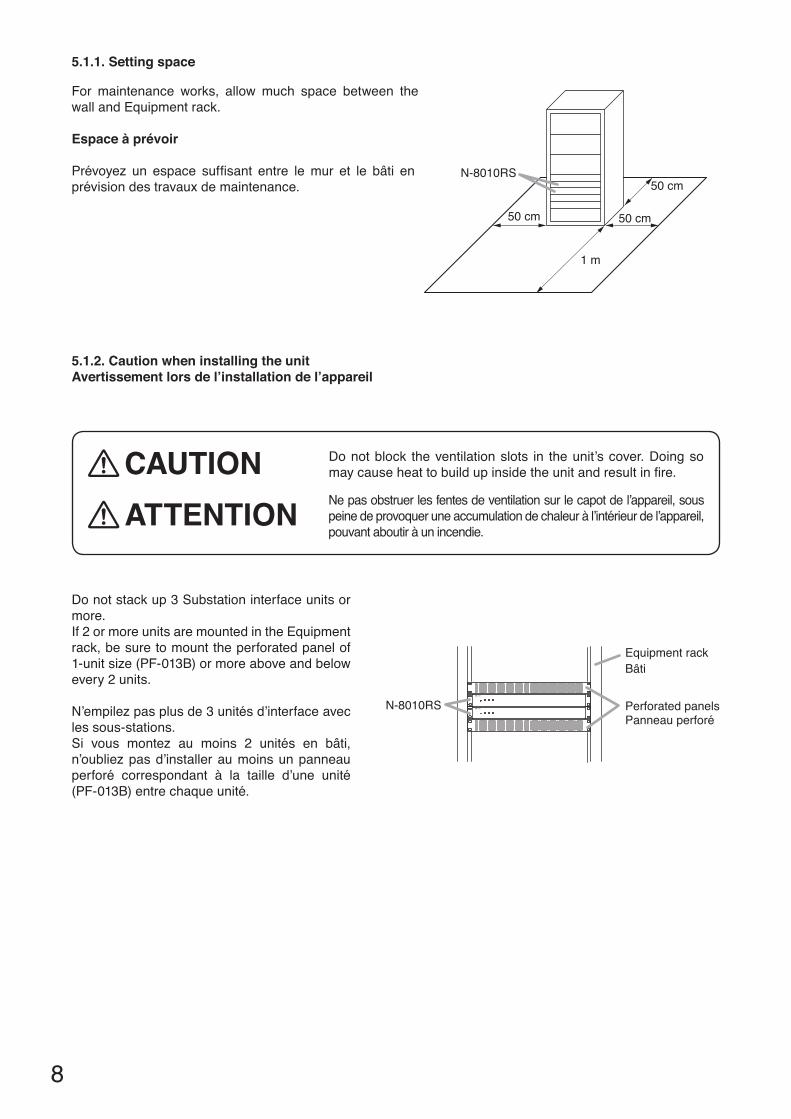
5.1.1. Setting space
For maintenance works, allow much space between the wall and Equipment rack.
espace à prévoir
Prévoyez un espace suffisant entre lemur et le bâti enprévisiondestravauxdemaintenance.
N-8010RS
50 cm 50 cm
1 m
50 cm
Perforated panels
Equipment rack
N-8010RS
Bâti
Panneau perforé
5.1.2. caution when installing the unitAvertissement lors de l’installation de l’appareil
Do not stack up 3 Substation interface units or more. If 2 or more units are mounted in the Equipment rack, be sure to mount the perforated panel of 1-unit size (PF-013B) or more above and below every 2 units.
N’empilezpasplusde3unitésd’interfaceavecles sous-stations. Si vous montez au moins 2 unités en bâti,n’oubliez pas d’installer au moins un panneau perforé correspondant à la taille d’une unité(PF-013B)entrechaqueunité.
Do not block the ventilation slots in the unit’s cover. Doing so maycauseheattobuildupinsidetheunitandresultinfire.cAUTIONNepasobstruerlesfentesdeventilationsurlecapotdel’appareil,souspeinedeprovoqueruneaccumulationdechaleuràl’intérieurdel’appareil,pouvantaboutiràunincendie.
ATTeNTION

9
5.1.3. Mounting on the rackMontage en bâti
Step 1. Installtherack-mountingbrackettotheN-8010RS.
Step 2. MounttheN-8010RSontheEquipmentrack.
Étape 1. Installezlapattedemontageenbâtisurl’unitéN-8010RS.
Étape 2. Montezl’unitéN-8010RSenbâti.
5.2. Desk-Top Installation
WheninstallingtheN-8010RSonadesk,securethesuppliedplasticfeettothebottomsurfaceoftheN-8010RSusing the supplied machine screws.
Installation sur un bureau
Pourinstallerl’unitésurunbureau,installezlespiedsenplastiquefournissurlefonddel’appareilàl’aidedesvis fournies.
N-8010RS
Rack mounting screw 5 x 12 with plain washer (accessory)
Rack mounting bracket (accessory)
Tapping screw 3 x 8 (accessory)
Patte de montage (accessoire)
Vis-taraud 3 x 8(accessoire)
(accessoire) Vis de montage en bâti 5 x 12 avec rondelle simple
12
N-8010RSPlastic foot (accessory)
Machine screw M3 x 8(accessory)
Vis de mécanique M3 x 8(accessoire)
Pied en plastique(accessoire)

10
5.3. Wall Mounting
Step 1. Install the optional YC-850 Wall-mounting brackettotheN-8010RS.
Step 2. MounttheN-8010RSonthewall.Notes• Use appropriate screws for the construction of
wall.• Wood screws 3.5 x 20 are supplied with the
YC-850.• The socket-outlet shall be installed near the
equipment and the plug (disconnecting device) shall be easily accessible.
Montage mural
Étape 1. Installez la patte demontage en bâti YC-850fournie.
Étape 2. Montezl’unitéN-8010RSaumur.remarques • Utilisezdesvisadaptéesàlastructuredumur.• L’unitéYC-850estlivréeavecdesvisàbois3,5x20.• Laprisedoitêtreinstalléeàproximitédel’équipementetlafiche(dispositifdedéconnexion)doitêtrefacilementaccessible.
N-8010RS
Machine screw M3 x 6(supplied with the YC-850)Vis de mécanique M3 x 6(fournie avec l'unité YC-850)
Power supply cordCordon d'alimentation
Cord clampCollier du cordon
Wood screw 3.5 x 20 (supplied with the YC-850)
Wall surface
Vis à bois 3,5 x 20 (fournie avec l'unité YC-850)
Surface murale
Protect against disconnection (Power supply plug)Unlock cord clamp and run the power supply cord through it.NoteKeep the cable length between a power supply plug and cord clamp as short as possible.
Protection contre les ruptures d'alimentation (prise d'alimentation) Déverrouillez le collier à cordon et glissez-y le cordon d'alimentation.RemarqueLe câble entre la prise d'alimentation et le collier doit être aussi court que possible.

11
6. WIrING6.1. connection Diagram
1 2 3
To AC mains or a UPS (Uninterruptible power supply system)*1
Note
Tips
If there is a danger of lightning strikes, insert an appropriate surge arrester into the power line.
Be sure to ground.3P removable terminal plug
(accessory)
2-core shielded cable
To network
RJ-45 connector
To Line A (orange)
To Line B (brown)
To Line C (black)
RS-140*2, RS-150, RS-160, RS-170, or RS-180
For more information on the RS-140, RS-150, RS-160, RS-170, and RS-180, please refer to their respectiveinstallation manuals.
16 lines
N-8010RS Substation interface unit
• • This figure represents the RS-180.
For the RS-140, connectioncable color differs from thefigure above.
*2
Line A: Brown, Line B: Red, Line C: Orange
[General description of connection]For cables, refer to p. 13.
1. Power supply connectionConnect the supplied power supply cord to AC Mains or a UPS (Uninterruptible power supply).
About power supply cord handlingThe supplied power supply cord is designed for exclusiveusewiththeN-8010RS.Neveruseitwithotherequipment.
2. Substation connections(Refer to p. 13, "Removable Terminal Plug Connection.")
3. Network connectionCan be connected to a network of 10BASE-T/100BASE-TXinauto-sensing.Use a straight through cable of UTP category 5 or more for this connection.
*1 Select an appropriate UPS taking into consideration the total power consumption of all system components and the required backup time. On-line uninterruptible power supply (UPS) is recommended.referenceSubstationinterfaceunitN-8010RS:30W(rated)forCEversion,25W(rated)forCUversion8-Port10M/100MSwitchingHub:Approx.10W(Differsdependingonproducts.)

12
cÂbLAGeSSchéma de branchements
1 2 3
Ne pas oublier la mise à la terre.
Vers prise secteur CA (ou système d'alimentation sans interruption)*1
RemarqueInstallez un parafoudre sur la ligne électrique pour protéger votre installation.
Prise 3P amovible(accessoire)
Câble blindé à deux brins
Connecteur RJ45
Vers le réseau
Vers ligne B (marron)
Vers ligne C (noir)
Vers ligne A (orange)
RS-140*2, RS-150, RS-160, RS-170, ou RS-180 *2 Sur le modèle RS-140,
la couleur du câble de connexionn'est pas celle représenté sur la figure ci-dessus.Ligne A : Marron, Ligne B : Rouge, Ligne C : Orange
Conseils• Cette figure représente l'unité RS-180.• Pour de plus amples informations sur les unités RS-140, RS-150, RS-160, RS-170 et RS-180, reportez-vous aux manuels d'installation correspondants.
16 lignes
Unité d'interface de sous-station N-8010RS
[Description générale des branchements]Pourlescâbles,reportez-vousàlapage13.
1. branchement à l'alimentationBranchez le cordon d'alimentation fourni sur la prise secteur CA (ou un système d'alimentationsans interruption).
À propos du maniement du cordon d'alimentationLe cordon d'alimentation fourni est exclusivement destinéàuneutilisationavecl'unitéN-8010RS.Nejamaisl'utiliseravecunautreéquipement.
2. branchement des sous-stations(Reportez-vous à la page 13, "RemovableTerminal Plug Connection.")
3. connexion réseauPeutêtreconnectéàunréseau10BASET/100BASE-TXenauto-détection.UtiliseruncâbledroitUTPdecatégorie5oupluspour ce branchement.
*1Choisissezlesystèmed'alimentationsanscoupureadaptéenprenantencomptelaconsommationélectriquetotale de l'ensemble des composants du système ainsi que la durée de récupération nécessaire. Nousrecommandonsunsystèmed'alimentationsanscoupureenfonctionnementcontinu.
référence Interfacepoursous-stationN-8010RS:30W(nominal)pourlaversionCE,25W(nominal)pourlaversionCU.8port10M/100Mconcentrateurdecommutation:Environ10W(enfonctiondesproduits.)

13
6.4. removable Terminal Plug connection
Step 1. Strip a cable jacket of approx. 7 mm to expose inner cable.
Step 2. Loosen the terminal screws and insert the cables.
Step 3. Tighten the terminal screws securely.Notes• Tuglightlyonthecabletobesurethatitdoesnotpullfree.Ifthecablepullsfree,loosentheterminal
screw again and reconnect from Step 2. • Usethescrewdriverappropriatetothescrewstightenedintotheterminalplug.
7 mm For cables, refer to above "Type of Cable."NoteDo not solder on exposed inner cables when using a stranded wire.
6.2. Type of cable
The types of cables are to be determined according to the following conditions.
• UTPCategory5straightthroughcablewithRJ45connectorsistobeusedforconnectingtoIPnetwork.• Thenumberofcablespairslaidshouldbedeterminedconsideringthepossibilityoffutureexpansionofthe
system.• Outdoorwiresshouldbeusedwherewiringpassesthroughinaccessibleareassuchasatticsorunderfloors
where the maintenance is not performed. Indoor wires may also be used, however, in case where there is no risk of deterioration due to exposure to heat, etc.
• Makesurethatthe2-coreshieldedcableisusedforwiringfromthesubstationinterfaceunittothesubstation(RS-150, RS-160, RS-170, and RS-180).
NoteSpecifications related to connections are as follows.
Removableterminalplug(N-8010RSlineterminal)Conductordiameter: ø0.5–2mm(AWG12–24),Solidwire/Strandedwire
Clip terminal (E-7000TB)Conductordiameter: ø0.4–0.8mm(AWG20–26),SolidwireOutsidediameter: ø0.5mmorbelow
6.3. relations between core Diameter of cable and Maximum cable Length
For the maximum cable (2-core shielded) length between the substation interface unit and the substation (RS-150, RS-160, RS-170, and RS-180), refer to the following table.
Conductor diameter (mm)
Maximum cable length(km)
ø0.5 0.5ø0.65 0.8ø0.9 1.3

14
Step 4. InsertthewiredterminalplugintotheterminalblockoftheN-8010RS.
N-8010RS rear panel
2
34
Removable terminal blockRemovable terminal plug (accessory)
Tighten
6.5. e-7000Tb Terminal board Wiring
For cable connection to the E-7000TB Terminal Board, use the optional YC-105 Clipping tool.Hooktheendofthecableontotheterminaland,withthecableendinhand,presstheYC-105downontotheterminal from above. Pressing down the YC-105 tool cuts off the excess cable end, securing the connection.
For cables, refer to p. 13, "Type of Cable."
Terminal board E-7000TBCable
Hook the cable onto the terminal without stripping the cablesheath.
Yellow Gray
Clipping tool YC-105 (Optional)
Bind the cables using the cord clamps supplied with the E-7000TB.
Cut end
Terminal

15
7. AcceSSOrIeS
* ContainstheN-8000SettingsoftwareprogramandtheN-8000seriesinstructionmanual.TheSetupLauncheris automatically started when the supplied CD-ROM is inserted into the PC's drive.NoteIf your PC's CD drive is not compatible with the AutoRun function, the setup guide is not automatically started evenwhentheCDisinserted.Useeither"Explorer"or"MyComputer"toexecutethefollowingfiles,oruse[Start Run] in the Task Bar and enter the following command.<Drive where CD is placed> \index.htmlFor example, when placing the CD in the "d" drive, d:\index.html
AC power cord (2 m) ............................................... 1CD* (for PC setting, maintenance use) .................. 1Removable terminal plug (3 pins) ......................... 16Plastic foot .............................................................. 4
Machine screw M3 x 8 ............................................ 4Rack mounting bracket ........................................... 2Tapping screw 3 x 8 ............................................... 8Rack mounting screw 5 x 12 with plain washer ...... 4
Cordon d’alimentation CA (2 m) ............................ 1CD*(pourleparamétrageduPC,destinéauservicedemaintenance) ............ 1Prise amovible (3 broches) .................................. 16Pied en plastique ................................................... 4
VisdemécaniqueM3x8 ...................................... 4Pattes de montage ................................................ 2Vis-taraud3x8 ..................................................... 8Visdemontageenbâti5x12 avec rondelle simple .................................... 4
* Contient le logicieldeparamétragedel’unitéN-8000ainsiquelanoticederéférencedelasérieN-8000.Leprogrammedelancementdelaconfigurationdémarreautomatiquementlorsdel’insertionduCD-ROMfourni dans le lecteur.remarqueSi le lecteurdeCDdevotrePCn’estpascompatibleaveclafonctiond’exécutionautomatique, l’assistantdeconfigurationnes’ouvrepasautomatiquementlorsdel’insertionduCD.Recherchezlesfichierssuivantsdans l’ExplorateurWindows,Poste de travail ou saisissez la commande ci-dessous après avoir lancé lafonction [Lancer L’exécution]delaBarredestâches.<LecteurdanslequelleCDaétéinséré>\index.html.Par exemple, pour l'insertion du CD dans le lecteur D d:\index.html
AcceSSOIreS
8. OPTIONAL PrODUcT
Wallmountingbracket: YC-850
PrODUIT eN OPTION
Pattesdemontagemural: YC-850

URL:http://www.toa.jp/
• DownloadourTOAProductsData,website(http://www.toa-products.com/international/) togettheup-to-dateversionforN-8000software,firmware,andInstructionmanuals.
• Thecurrentfirmwareversioncanbeconfirmedonthesystemmanagementscreendisplayedwhenthe browser establishes the connection to the Substation interface unit.
• ThesoftwareversionnumbercanbeconfirmedusingtheHelpmenu.• Theinstructionmanualversionnumbercanbeconfirmedbycheckingthepreparationdate(month
and year) shown at the lower right corner of the last page. Example:PreparedinSeptember2009:200909
Version update information
133-06-00010-00
• Les fiches techniques des produits TOA sont disponibles au téléchargement sur le site web àl’adressehttp://www.toa-products.com/international/ où vous trouverezégalement les versions lesplusrécentesdulogiciel,dumicroprogrammeetdesnoticesderéférencedel’unitéN-8000.
• Pourvérifierlaversiondumicroprogramme,consultezl’écrand’administrationdusystèmequis’affichelorsquelenavigateurseconnecteàl’interfacedelasous-station.
• LaversiondulogicielestindiquéedanslemenuAide.• Lenumérodeversiondelanoticederéférenceestindiquédanslecoinintérieurdroitdeladernièrepageetcorrespondàladatedesapublication(moisetannée).
Exemple:Publiéenseptembre2009:200909.
Informations sur les versions de mise à jour
Traceability Information for europeRenseignementsrelatifsàlatraçabilitéenEurope
Manufacturer:Fabricant:
TOA Corporation7-2-1,Minatojima-Nakamachi,Chuo-ku,Kobe,Hyogo,Japan
Authorizedrepresentative:Représentantagréé:TOAElectronicsEuropeGmbHSuederstrasse282,20537Hamburg,Germany