submitted to: submitted by
TRANSCRIPT
Temporary Works Geotechnical Report
Bridge Nos. 01218, 04180 I-84 EB/WB over Housatonic River Newtown/Southbury, Connecticut
Submitted to: CME Associates, Inc. 101 East River Drive East Hartford, CT 06108
Submitted by: GEI Consultants, Inc. 455 Winding Brook Drive, Suite 201 Glastonbury, CT 06033 860-368-5300
October 11, 2019 GEI Project No. 125810
Matthew Glunt, P.E. Senior Geotechnical Engineer
Michael Flynn, P.E. (MA) Senior Engineer
Consulting
Engineers and
Scientists

T E M P O R A R Y W O R K S G E O T E C H N I C A L R E P O R T C T D O T B R I D G E N O S . 0 1 2 1 8 , 0 4 1 8 0 I - 8 4 E B / W B O V E R H O U S A T O N I C R I V E R N E W T O W N / S O U T H B U R Y , C O N N E C T I C U T O C T O B E R 1 1 , 2 0 1 9
GEI Consultants, Inc. i
Table of Contents
1. Introduction 1 1.1 Project Summary 1 1.2 Purpose 1 1.3 Scope of Services 1 1.4 Datum 2
2. Site and Project Description 3 2.1 Site Description 3 2.2 Project Description 3
3. Exploration Procedures 4 3.1 Test Borings 4 3.2 Historic Borings 4
4. Subsurface Conditions 5 4.1 Geologic Setting 5 4.2 Subsurface Conditions 5 4.3 Groundwater Conditions 7
5. Temporary Works Considerations 8 5.1 General 8 5.2 Soil Properties 8 5.3 North and South Haul Road 9
5.3.1 General Considerations 9 5.3.2 Alternatives 9 5.3.3 Global Slope Stability 9 5.3.4 Groundwater Controls 10
5.4 Work Trestle Foundations 10 5.4.1 General Considerations 10 5.4.2 Foundation Alternatives 10 5.4.3 Pile Installation 10
6. Limitations 12

T E M P O R A R Y W O R K S G E O T E C H N I C A L R E P O R T C T D O T B R I D G E N O S . 0 1 2 1 8 , 0 4 1 8 0 I - 8 4 E B / W B O V E R H O U S A T O N I C R I V E R N E W T O W N / S O U T H B U R Y , C O N N E C T I C U T O C T O B E R 1 1 , 2 0 1 9
GEI Consultants, Inc. ii
Figures
1. Boring Location Plan
Appendices
A. Boring Logs B. Relevant Historical Data

T E M P O R A R Y W O R K S G E O T E C H N I C A L R E P O R T C T D O T B R I D G E N O S . 0 1 2 1 8 , 0 4 1 8 0 I - 8 4 E B / W B O V E R H O U S A T O N I C R I V E R N E W T O W N / S O U T H B U R Y , C O N N E C T I C U T O C T O B E R 1 1 , 2 0 1 9
GEI Consultants, Inc. 1
1. Introduction
1.1 Project Summary
The project consists of rehabilitation of Bridge Nos. 01218 and 04180, carrying I-84 eastbound and westbound, respectively, over the Housatonic River in Newtown and Southbury, Connecticut.
1.2 Purpose
GEI Consultants, Inc. (GEI) was retained to perform a subsurface exploration program and prepare this Geotechnical Report in support of the temporary works required for this project, which are to include work trestles and associated temporary haul roads in the median areas to the north and south of the bridge alignments. This report presents the results of the subsurface explorations, relevant historic data, our evaluation of the subsurface conditions, and geotechnical considerations for use by the Contractor’s engineer in design of the temporary works.
1.3 Scope of Services
GEI’s scope of work in regard to temporary works included the following:
1. Reviewed available published geologic data, existing bridge plans, and proposed bridge design information provided to us.
2. Developed a subsurface exploration program, consisting seven (7) borings (HR-1 through HR-7) advanced within or near the proposed haul road alignments to depths between 22 and 52 feet.
3. Provided full-time observation of the test borings and classified recovered samples in general accordance with Connecticut Department of Transportation (ConnDOT) Geotechnical Engineering Manual.
4. Reviewed the results of the geotechnical explorations and developed recommended soil properties for temporary works design.
5. Conduct global slope stability analysis at maximum (critical) excavation depth along north and south haul road alignments.
6. Presented the results of the explorations and geotechnical considerations for temporary works design in this report.

T E M P O R A R Y W O R K S G E O T E C H N I C A L R E P O R T C T D O T B R I D G E N O S . 0 1 2 1 8 , 0 4 1 8 0 I - 8 4 E B / W B O V E R H O U S A T O N I C R I V E R N E W T O W N / S O U T H B U R Y , C O N N E C T I C U T O C T O B E R 1 1 , 2 0 1 9
GEI Consultants, Inc. 2
1.4 Datum
Elevations shown on the attached boring logs were estimated from the project survey, as referenced to NAVD 88. Historical information, where referenced herein and on attachments, is referenced to NGVD29.

T E M P O R A R Y W O R K S G E O T E C H N I C A L R E P O R T C T D O T B R I D G E N O S . 0 1 2 1 8 , 0 4 1 8 0 I - 8 4 E B / W B O V E R H O U S A T O N I C R I V E R N E W T O W N / S O U T H B U R Y , C O N N E C T I C U T O C T O B E R 1 1 , 2 0 1 9
GEI Consultants, Inc. 3
2. Site and Project Description
2.1 Site Description
Bridge No. 01218 is a four-span, continuous plate girder structure that carries I-84 Eastbound over the Housatonic River from Newtown to Southbury, Connecticut. This structure was originally built in 1953 for the relocation of US Route 6 and was reconstructed in 1979 as part of the building of I-84. The bridge carries 2 lanes of eastbound traffic and a sidewalk, outboard of the south parapet. The total structure length is approximately 792 feet.
Bridge No. 04180 is a four-span, continuous plate girder structure that carries two lanes of I-84 Westbound over the Housatonic River from Southbury to Newtown, Connecticut. This structure was built in 1977. The total structure length is approximately 792 feet.
Both bridges are supported by reinforced concrete piers and abutments with a combination of vertical and battered steel H-piles driven to presumed bedrock. These H-piles extend to varying depths, ranging from approximately 26 to 112 feet below the pile caps. Summary tables of historic pile installations are provided in Appendix B, as this may be of some interest to foundation design of the work trestle. This information is provided for reference purposes only.
2.2 Project Description
GEI was provided a copy of the Final Design plans prepared by Louis Berger/WSP dated May 30, 2019.
Temporary works on the project are to consist of the following:
Temporary work trestles on the south (Site No. 2) and north (Site No. 1) sides of the bridge alignment.
Temporary access/haul roads within the median areas, terminating at each work trestle.
We understand both the trestles and access roads will be constructed during Stage 1 of the project.

T E M P O R A R Y W O R K S G E O T E C H N I C A L R E P O R T C T D O T B R I D G E N O S . 0 1 2 1 8 , 0 4 1 8 0 I - 8 4 E B / W B O V E R H O U S A T O N I C R I V E R N E W T O W N / S O U T H B U R Y , C O N N E C T I C U T O C T O B E R 1 1 , 2 0 1 9
GEI Consultants, Inc. 4
3. Exploration Procedures
3.1 Test Borings
New England Boring Contractors, Inc. (NEBC), under subcontract to CME, drilled seven (7) borings along or near the proposed haul road alignments between August 5 and August 29, 2019. A GEI representative observed the drilling procedures and classified the soil samples obtained. Each boring was advanced using solid-stem augers to a depth of 10 feet, then drive and wash techniques to termination depth. Standard Penetration tests and split-spoon sampling were conducted at 5-foot intervals. The boreholes were advanced using a truck-mounted drilling rig equipped with a 140-lb safety hammer or 140-lb automatic hammer, as noted on the boring logs. After each boring was completed, the holes were backfilled with drill cuttings supplemented by Portland cement, No. 2 sand, and/or ¾” stone. All borings were patched at the road surface using cold patch asphalt. Approximate boring locations relative to existing conditions are shown on Figure 1. Boring logs are attached in Appendix A.
3.2 Historic Borings
Borings were previously conducted from the shoreline and within the river to support design and construction of the current bridges - seventeen (17) borings along Bridge No. 01218 and twelve (12) borings along Bridge No. 04180. The results of these borings are presented on the 1950 and 1971 record drawings, which are attached in Appendix B in original form for reference.

T E M P O R A R Y W O R K S G E O T E C H N I C A L R E P O R T C T D O T B R I D G E N O S . 0 1 2 1 8 , 0 4 1 8 0 I - 8 4 E B / W B O V E R H O U S A T O N I C R I V E R N E W T O W N / S O U T H B U R Y , C O N N E C T I C U T O C T O B E R 1 1 , 2 0 1 9
GEI Consultants, Inc. 5
4. Subsurface Conditions
4.1 Geologic Setting
The project area lies in the floodplain of the Housatonic River. The Surficial Materials Map of Connecticut (Stone, 1992) shows outwash sand and gravel overlying sand along the northern shore and outwash sand and gravel along the southern shore. River channel sediments are likely in sequence of outwash sand and gravel (stratified drift) over glacial till, likely with some lateral variation across the channel.
The Bedrock Geological Map of Connecticut (Rodgers, 1985) shows the Collinsville Formation present in the project area on both banks of the Housatonic River. The Collinsville Formation is described as a combination of gray and silvery, medium- to coarse-grained schist, dark, fine- to medium-grained amphibolite, and hornblende gneiss.
4.2 Subsurface Conditions
Based on our review of the available geotechnical information, the general soil strata are as follows, beginning at the ground surface. The subsurface conditions are known only at the exploration locations. Conditions between explorations may differ significantly from those described below.
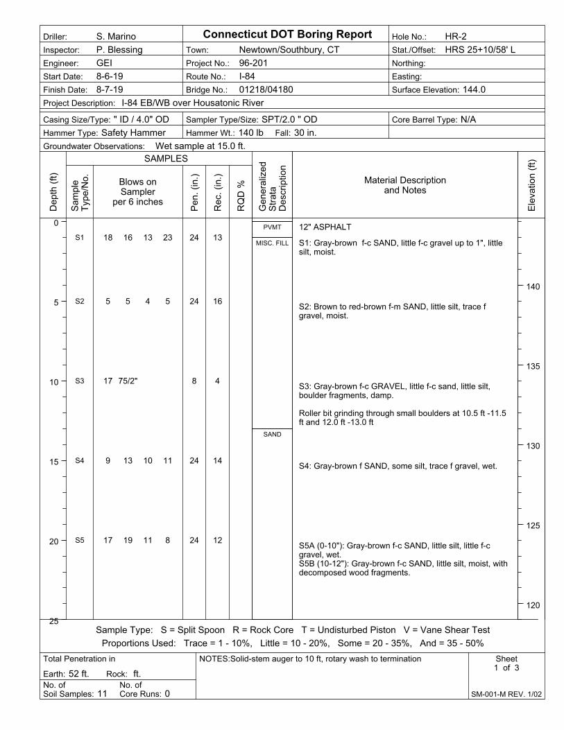
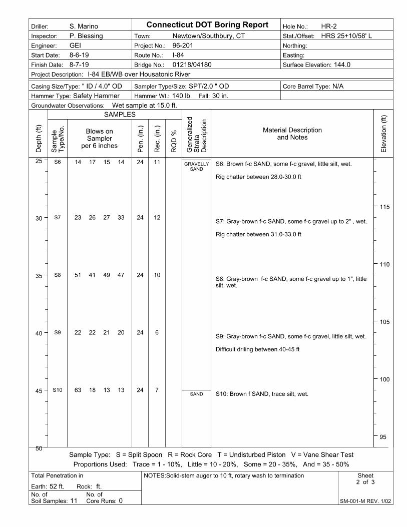
I. Embankment Fill – The ground surface contours atop which the eastbound I-84 embankment was built can be found on Sheet No. 2 from the 1950 drawing set for Bridge No. 01218. Recent borings conducted through the westbound embankment show similar results for embankment thickness. South of the bridge, borings HR-1 through HR-3 indicate Embankment Fill extending to approximate El. 131 ft. Recovered samples were classified as primarily fine to coarse-grained sand with variable proportions of gravel and generally less than 5 percent fine material. In boring HR-2, small boulders (up to about 12 inches in size) were encountered near the base of the fill, between depths of approximately 10.5 feet and 13.0 feet. This may signify a previous road base, stabilization course for the current embankment, or otherwise. Uncorrected Standard Penetration Test (SPT) N-values ranged from 9 to 46 blows/foot, indicating loose to dense conditions. As can be seen from the record drawings and from aerial photographs, the north abutments of both bridges and approximately 200 feet of the trailing embankments were extended into the river channel. As such, borings HR-4, HR-5, and HR-6 north of the bridges encountered Embankment Fill to approximate El. 99 ft., El. 105 ft., and El. 116 ft. respectively.
T E M P O R A R Y W O R K S G E O T E C H N I C A L R E P O R T C T D O T B R I D G E N O S . 0 1 2 1 8 , 0 4 1 8 0 I - 8 4 E B / W B O V E R H O U S A T O N I C R I V E R N E W T O W N / S O U T H B U R Y , C O N N E C T I C U T O C T O B E R 1 1 , 2 0 1 9
GEI Consultants, Inc. 6
Recovered samples were classified as primarily fine to coarse-grained sand with variable proportions of gravel, occasional cobbles, and generally less than 5 percent fine material. In boring HR-5, concrete debris was encountered between depths of approximately 5.6 and 7.0 feet. Uncorrected Standard Penetration Test (SPT) N-values generally ranged from 7 to 48 blows/foot, indicating loose to dense conditions. A seam of very loose sand approximately 10 feet deep in HR-6 may have been influenced by advancement of the drilling tools. Seams of very dense material with SPT N-values in excess of 50 blows/foot were also noted. II. Riverbed Sediment – Riverbed sediment was encountered in the channel at the mudline and continuing for 2 to 14 feet. This layer is described on the historic logs as primarily dark gray fine sand with a variable amount of organic silt and trace of vegetation. In boring HR-5, the previous mudline or immediate shoreline was encountered at approximate El. 105, signified by approximately 3 feet of sandy Organic Silt. The uncorrected SPT N-value in this material was measured as 8 blows/foot. Although not encountered within other borings, there is potential that similar organic alluvial materials exist directly below the embankment adjacent to the current and former river channel. III. Native Sand – South of the bridges, an upper stratum of Sand was encountered in borings HR-1, HR-2, and HR-3 extending approximately to between El. 120 ft. and El. 115 ft. These soils were generally classified as primarily fine to coarse-grained sand with variable proportion of silt and trace amount of gravel. Uncorrected Standard Penetration Test (SPT) N-values generally ranged from 21 to 36 blows/foot, indicating medium dense to dense conditions. Within the river channel, historic borings on the north side encountered a stratum of surficial sands, consisting primarily of red-brown fine sand with little silt and some fine gravel. This stratum varies in thickness from 2 to 12 feet.
IV. Sand and Gravel – Dense to very dense Sand and Gravel was encountered below the Riverbed Sediment and Native Sand, continuing to bedrock. Generally, this stratum consists of yellow-brown to brown sand, some gravel, trace amount of silt, and occasional to frequent cobble or boulder-laden seams more prevalent on the north side of the channel. Typically, SPT N-values are in excess of 50 blows/foot.
Bedrock – Bedrock within the river channel is described on the historic logs as gray, metamorphic schistose gneiss. The quality of the rock cores was highly variable from location to location. Although some cores had excellent recovery (greater than 90 percent), several cores were noted as fractured or even shattered with very poor recoveries. Quartz veins were occasionally noted. Depth to bedrock varied widely across the site and was

T E M P O R A R Y W O R K S G E O T E C H N I C A L R E P O R T C T D O T B R I D G E N O S . 0 1 2 1 8 , 0 4 1 8 0 I - 8 4 E B / W B O V E R H O U S A T O N I C R I V E R N E W T O W N / S O U T H B U R Y , C O N N E C T I C U T O C T O B E R 1 1 , 2 0 1 9
GEI Consultants, Inc. 7
encountered at shallower depths moving southward across the alignment. Top of rock elevation varied from El. 36 ft to El. 100 ft (NGVD 29).
4.3 Groundwater Conditions
Because drilling fluids were introduced in each boring after advancement to 10 feet, true groundwater measurements were not obtainable in each borehole at the time of drilling. Wet samplers were noted at depths of 15 to 25 feet within the borings, generally corresponding to approximate El. 120 ft. to El. 115 ft. It would appear from the investigation that groundwater may be present near the transition from native Sand (Stratum III) to dense lower Sand and Gravel (Stratum IV).

T E M P O R A R Y W O R K S G E O T E C H N I C A L R E P O R T C T D O T B R I D G E N O S . 0 1 2 1 8 , 0 4 1 8 0 I - 8 4 E B / W B O V E R H O U S A T O N I C R I V E R N E W T O W N / S O U T H B U R Y , C O N N E C T I C U T O C T O B E R 1 1 , 2 0 1 9
GEI Consultants, Inc. 8
5. Temporary Works Considerations
Design of temporary works required for the project will be done via contractor design and submittal based on their means and methods. These works should be designed by a Connecticut-registered professional engineer experienced in such construction. Based on the investigation results, preliminary geotechnical considerations for this work are provided below.
Considerations presented herein for design and construction of temporary works are based on GEI’s interpretation of subsurface conditions and the conceptual layouts provided. The Contractor’s design engineer shall undertake their own independent review of the subsurface data presented within this report.
5.1 General
Our services were performed in general conformance with the ConnDOT Geotechnical Engineering Manual and our approved scope dated December 18, 2018.
5.2 Soil Properties
Recommended in-place soil properties for design of the temporary works are presented below. We estimated these values based on published correlations to SPT N-values and visual soil descriptions.
Table 1 – In-place Soil Properties
STRATUM
Angle of Internal Friction
(°)
Cohesion (C)
Moist Unit Weight ()
(lb/ft3)
(I) Embankment Fill 32 0 125
(II) Riverbed Sediment 24 0 95
(IIIA) Native Sands (South, above river level)
36 0 125
(IIIB) Native Sands (North, within river channel)
34 0 125
(IV) Lower Sand and Gravel 38 0 135
T E M P O R A R Y W O R K S G E O T E C H N I C A L R E P O R T C T D O T B R I D G E N O S . 0 1 2 1 8 , 0 4 1 8 0 I - 8 4 E B / W B O V E R H O U S A T O N I C R I V E R N E W T O W N / S O U T H B U R Y , C O N N E C T I C U T O C T O B E R 1 1 , 2 0 1 9
GEI Consultants, Inc. 9
5.3 North and South Haul Road
5.3.1 General Considerations
The proposed north and south haul roads ending at each work trestle will be constructed primarily through Embankment Fill (Stratum I) and Native Sand (Stratum III). Groundwater may be encountered below approximate El. 120 ft. as the lowest portion (and deepest excavation) of the haul roads are constructed. Given the variability in Stratum I and the potential for groundwater at depth, we recommend that temporary excavation slopes be no steeper than 2H:1V. This will necessitate the use of temporary earth retaining systems (TERS) up to 20 feet in height on both sides of the excavation for a majority of the haul road alignments.
5.3.2 Alternatives
Based on the subsurface conditions and the project constraints, the following alternatives appear to be feasible for use on this project:
1. Soil Nail walls 2. Soldier-pile and Lagging walls
Soil nail wall design must take into account utilities behind the wall, in particular the temporary 15-inch RCP near the south trestle, and the potential for groundwater intrusion near the base of the wall. Sheet piles are likely to encounter significant difficulty when driving through very dense cobble-laden Sands and Gravel (Stratum IV), and therefore are not likely to achieve sufficient embedment. Temporary MSE systems will also likely not be feasible due to constraints regarding embedment of the reinforcement towards active travel lanes. Another system(s) not specifically mentioned herein or a hybrid TERS may also be feasible, subject to design and construction considerations presented by the Contractor’s engineer.
5.3.3 Global Slope Stability
Global slope stability was checked at the maximum haul road cut section on each side of the bridges for conceptual soil nail wall configurations. The limit equilibrium analysis assumed a circular failure surface and no failure through the TERS. Proposed conditions were modeled using the Slope/W-GeoStudio software package, using the soil input properties in Table 1 and the haul road cross-sections from the design plans.

T E M P O R A R Y W O R K S G E O T E C H N I C A L R E P O R T C T D O T B R I D G E N O S . 0 1 2 1 8 , 0 4 1 8 0 I - 8 4 E B / W B O V E R H O U S A T O N I C R I V E R N E W T O W N / S O U T H B U R Y , C O N N E C T I C U T O C T O B E R 1 1 , 2 0 1 9
GEI Consultants, Inc. 10
Assuming soil nails extend at least 70 percent of the TERS height behind the face (as normal to the wall face), the factor of safety against global, deep-seated slope instability of the full haul road excavation is in excess of 1.25. This meets the requirements stated in Section 6-1.3.1 of the ConnDOT Geotechnical Manual.
5.3.4 Groundwater Controls
The presence or absence of a shallow groundwater aquifer above the river level was not confirmed by the recent investigation. At the least, it can be presumed from the investigation that seams of water perched on very dense soils will be present between approximate El. 120 ft. and El. 115 ft. during and following rainfall events. Groundwater controls should be anticipated for all work that occurs below these elevations.
5.4 Work Trestle Foundations
5.4.1 General Considerations
Concept plans prepared by Louis Berger/WSP show a 149.7-foot-long trestle on the south alignment (Site No. 2), a 368.7-foot-long trestle on the north alignment (Site No. 1), and clearance for a barge-mounted crane between. Foundations are shown as 24-inch diameter piles at maximum 20-foot spacing. The temporary work trestles and associated falsework shall be designed by the Contractor in accordance with the AASHTO Guide Design Specifications for Bridge Temporary Works 1st Edition, 1995, with latest revisions, along with the project specifications and 07-Construction drawing package.
5.4.2 Foundation Alternatives
Steel pipe piles driven into the dense lower sand and gravel (Stratum IV) or to refusal on rock appear to be suitable for support of the proposed temporary work trestle. If required for additional capacity, drilled rock sockets may be installed in the pipe piles, subject to analysis by the Contractor’s engineer. Special attention should be paid to the presence of boulders and very dense soils below the trestle alignments that could cause issues during pile installation.
5.4.3 Pile Installation
Boring data presented on the 1950 and 1972 record drawings, attached in Appendix B, indicate a presence of frequent cobbles, boulders, and very dense soil zones, as evidenced by the strata descriptions (“BOULDER”, “hardpan”, etc.), SPT N-values in excess of 150 blows/foot, and 300-lb hammer blows on the steel casing in excess of 200 blows/foot. These conditions should be anticipated for trestle foundation installation, particularly for the north trestle. The Contractor should be prepared to implement special measures such as hardened

T E M P O R A R Y W O R K S G E O T E C H N I C A L R E P O R T C T D O T B R I D G E N O S . 0 1 2 1 8 , 0 4 1 8 0 I - 8 4 E B / W B O V E R H O U S A T O N I C R I V E R N E W T O W N / S O U T H B U R Y , C O N N E C T I C U T O C T O B E R 1 1 , 2 0 1 9
GEI Consultants, Inc. 11
driving shoes, pre-drilling, reaming, etc. to prevent shallow pile refusals on boulders or very dense soils. Means and methods for overcoming these conditions, including contingency measures, should be included within the trestle foundation pile submittals. If driven piles are to be used, prior to driving, a wave equation (WEAP) analysis of the proposed pile-hammer system should be performed to check that the necessary capacity can be achieved without overstressing the piles, and to establish preliminary driving criteria. This analysis should be submitted for review by the Contractor’s engineer within the trestle foundation submittal. The WEAP analysis should be performed by the Contractor in accordance with ConnDOT specifications.

T E M P O R A R Y W O R K S G E O T E C H N I C A L R E P O R T C T D O T B R I D G E N O S . 0 1 2 1 8 , 0 4 1 8 0 I - 8 4 E B / W B O V E R H O U S A T O N I C R I V E R N E W T O W N / S O U T H B U R Y , C O N N E C T I C U T O C T O B E R 1 1 , 2 0 1 9
GEI Consultants, Inc. 12
6. Limitations
The preliminary geotechnical considerations presented within this report are based on the project information provided to us at the time of this report and may require modification if there are any changes in the nature, design, or location of the proposed temporary works construction. We recommend that GEI be engaged to review the Contractor’s design submittals and installation records. The considerations in this report are based in part on the data obtained from the borings. The nature and extent of variations between borings may not become evident until construction. If variations from the anticipated conditions are encountered, it may be necessary to revise the considerations in this report. Our professional services for this project have been performed in accordance with generally accepted engineering practices; no warranty, express or implied, is made.

T E M P O R A R Y W O R K S G E O T E C H N I C A L R E P O R T C T D O T B R I D G E N O S . 0 1 2 1 8 , 0 4 1 8 0 I - 8 4 E B / W B O V E R H O U S A T O N I C R I V E R N E W T O W N / S O U T H B U R Y , C O N N E C T I C U T O C T O B E R 1 1 , 2 0 1 9
GEI Consultants, Inc.
Figures

05.10
HR-1
HR-2

05.11
HR-3HR-4

05.12
HR-5
HR-7HR-6

T E M P O R A R Y W O R K S G E O T E C H N I C A L R E P O R T C T D O T B R I D G E N O S . 0 1 2 1 8 , 0 4 1 8 0 I - 8 4 E B / W B O V E R H O U S A T O N I C R I V E R N E W T O W N / S O U T H B U R Y , C O N N E C T I C U T O C T O B E R 1 1 , 2 0 1 9
GEI Consultants, Inc.
Appendix A
Boring Logs

S1
S2
S3
S4
S5
12" ASPHALT
S1: Brown to gray-brown f-c SAND, some f-c gravel up to1", trace silt, cobble fragments, dry.
S2: Brown f-c SAND, little f-c gravel up to 1.5", trace silt,cobble fragments, dry.
S3: Brown f-c SAND, little silt, trace f gravel up to 0.5",moist.
S4: Brown to red-brown f SAND, little silt, trace f -mgravel up to 1", some fine roots, moist.
S5: Orange-brown f-c SAND, little silt, trace f-c gravel upto 1", moist.
15
16
21
8
18
PVMT
MISC. FILL
SAND
22 19 22 34
12 24 22 16
12 8 12 20
16 18 15 11
18 13 12 42
24
24
24
24
24
Finish Date: 8-7-19
Sam
ple
Typ
e/N
o. Material Descriptionand Notes
Northing:
Easting:
No. ofSoil Samples: 9
Surface Elevation: 145.5
Hammer Type: Safety Hammer
Sampler Type/Size: SPT/2.0 " OD
Rec
. (in
.)
Dep
th (
ft)
0
5
10
15
20
25
Project No.: 96-201
Gen
eral
ized
Str
ata
Des
crip
tion
Sample Type: S = Split Spoon R = Rock Core T = Undisturbed Piston V = Vane Shear Test
Proportions Used: Trace = 1 - 10%, Little = 10 - 20%, Some = 20 - 35%, And = 35 - 50%
Hole No.: HR-1
Sheet1 of 2
SAMPLES
SM-001-M REV. 1/02
Connecticut DOT Boring Report
Casing Size/Type: " ID / 4.0" OD
Town: Newtown/Southbury, CT
Rock: ft.
Ele
vatio
n (f
t)
145
140
135
130
125
Hammer Wt.: 140 lb
Inspector: P. Blessing
RQ
D %
Core Barrel Type: N/A
Total Penetration in NOTES:Solid-stem auger to 10 ft, rotary wash to termination
No. ofCore Runs: 0
Fall: 30 in.
Project Description: I-84 EB/WB over Housatonic River
Stat./Offset: HRS 23+55/70' L
Blows onSampler
per 6 inchesP
en.
(in.)
Groundwater Observations: Wet sample at 25.0 ft
Driller: S. Marino
Start Date: 8-7-19
Bridge No.: 01218/04180
Route No.: I-84
Engineer: GEI
Earth: 42 ft.

S6
S7
S8
S9
S6: Brown to gray-brown f-c GRAVEL up to 1", some f-csand, trace silt, wet.
S7: Brown to orange-brown f-c SAND, some f-c gravel upto 1.5", little silt, wet.
S8: Brown to gray-brown f-c GRAVEL up to 1" and f-mSAND, trace silt, wet.
S9: Brown to red-brown f-c SAND and f-c GRAVEL up to1.5", little silt, wet.
End of Boring at 42 ft.
Borehole backfilled and asphalt patched upon completion.
12
17
16
16
SANDYGRAVEL
GRAVELLYSAND
SANDYGRAVEL
GRAVELLYSAND
16 11 10 9
26 29 33 36
21 41 42 47
19 33 29 35
24
24
24
24
Finish Date: 8-7-19
Sam
ple
Typ
e/N
o. Material Descriptionand Notes
Northing:
Easting:
No. ofSoil Samples: 9
Surface Elevation: 145.5
Hammer Type: Safety Hammer
Sampler Type/Size: SPT/2.0 " OD
Rec
. (in
.)
Dep
th (
ft)
25
30
35
40
Project No.: 96-201
Gen
eral
ized
Str
ata
Des
crip
tion
Sample Type: S = Split Spoon R = Rock Core T = Undisturbed Piston V = Vane Shear Test
Proportions Used: Trace = 1 - 10%, Little = 10 - 20%, Some = 20 - 35%, And = 35 - 50%
Hole No.: HR-1
Sheet2 of 2
SAMPLES
SM-001-M REV. 1/02
Connecticut DOT Boring Report
Casing Size/Type: " ID / 4.0" OD
Town: Newtown/Southbury, CT
Rock: ft.
Ele
vatio
n (f
t)
120
115
110
105
Hammer Wt.: 140 lb
Inspector: P. Blessing
RQ
D %
Core Barrel Type: N/A
Total Penetration in NOTES:Solid-stem auger to 10 ft, rotary wash to termination
No. ofCore Runs: 0
Fall: 30 in.
Project Description: I-84 EB/WB over Housatonic River
Stat./Offset: HRS 23+55/70' L
Blows onSampler
per 6 inchesP
en.
(in.)
Groundwater Observations: Wet sample at 25.0 ft
Driller: S. Marino
Start Date: 8-7-19
Bridge No.: 01218/04180
Route No.: I-84
Engineer: GEI
Earth: 42 ft.
S1
S2
S3
S4
S5
12" ASPHALT
S1: Gray-brown f-c SAND, little f-c gravel up to 1", littlesilt, moist.
S2: Brown to red-brown f-m SAND, little silt, trace fgravel, moist.
S3: Gray-brown f-c GRAVEL, little f-c sand, little silt,boulder fragments, damp.
Roller bit grinding through small boulders at 10.5 ft -11.5ft and 12.0 ft -13.0 ft
S4: Gray-brown f SAND, some silt, trace f gravel, wet.
S5A (0-10"): Gray-brown f-c SAND, little silt, little f-cgravel, wet.S5B (10-12"): Gray-brown f-c SAND, little silt, moist, withdecomposed wood fragments.
13
16
4
14
12
PVMT
MISC. FILL
SAND
18 16 13 23
5 5 4 5
17 75/2"
9 13 10 11
17 19 11 8
24
24
8
24
24
Finish Date: 8-7-19
Sam
ple
Typ
e/N
o. Material Descriptionand Notes
Northing:
Easting:
No. ofSoil Samples: 11
Surface Elevation: 144.0
Hammer Type: Safety Hammer
Sampler Type/Size: SPT/2.0 " OD
Rec
. (in
.)
Dep
th (
ft)
0
5
10
15
20
25
Project No.: 96-201
Gen
eral
ized
Str
ata
Des
crip
tion
Sample Type: S = Split Spoon R = Rock Core T = Undisturbed Piston V = Vane Shear Test
Proportions Used: Trace = 1 - 10%, Little = 10 - 20%, Some = 20 - 35%, And = 35 - 50%
Hole No.: HR-2
Sheet1 of 3
SAMPLES
SM-001-M REV. 1/02
Connecticut DOT Boring Report
Casing Size/Type: " ID / 4.0" OD
Town: Newtown/Southbury, CT
Rock: ft.
Ele
vatio
n (f
t)
140
135
130
125
120
Hammer Wt.: 140 lb
Inspector: P. Blessing
RQ
D %
Core Barrel Type: N/A
Total Penetration in NOTES:Solid-stem auger to 10 ft, rotary wash to termination
No. ofCore Runs: 0
Fall: 30 in.
Project Description: I-84 EB/WB over Housatonic River
Stat./Offset: HRS 25+10/58' L
Blows onSampler
per 6 inchesP
en.
(in.)
Groundwater Observations: Wet sample at 15.0 ft.
Driller: S. Marino
Start Date: 8-6-19
Bridge No.: 01218/04180
Route No.: I-84
Engineer: GEI
Earth: 52 ft.
S6
S7
S8
S9
S10
S6: Brown f-c SAND, some f-c gravel, little silt, wet.
Rig chatter between 28.0-30.0 ft
S7: Gray-brown f-c SAND, some f-c gravel up to 2" , wet.
Rig chatter between 31.0-33.0 ft
S8: Gray-brown f-c SAND, some f-c gravel up to 1", littlesilt, wet.
S9: Gray-brown f-c SAND, some f-c gravel, little silt, wet.
Difficult driling between 40-45 ft
S10: Brown f SAND, trace silt, wet.
11
12
10
6
7
GRAVELLYSAND
SAND
14 17 15 14
23 26 27 33
51 41 49 47
22 22 21 20
63 18 13 13
24
24
24
24
24
Finish Date: 8-7-19
Sam
ple
Typ
e/N
o. Material Descriptionand Notes
Northing:
Easting:
No. ofSoil Samples: 11
Surface Elevation: 144.0
Hammer Type: Safety Hammer
Sampler Type/Size: SPT/2.0 " OD
Rec
. (in
.)
Dep
th (
ft)
25
30
35
40
45
50
Project No.: 96-201
Gen
eral
ized
Str
ata
Des
crip
tion
Sample Type: S = Split Spoon R = Rock Core T = Undisturbed Piston V = Vane Shear Test
Proportions Used: Trace = 1 - 10%, Little = 10 - 20%, Some = 20 - 35%, And = 35 - 50%
Hole No.: HR-2
Sheet2 of 3
SAMPLES
SM-001-M REV. 1/02
Connecticut DOT Boring Report
Casing Size/Type: " ID / 4.0" OD
Town: Newtown/Southbury, CT
Rock: ft.
Ele
vatio
n (f
t)
115
110
105
100
95
Hammer Wt.: 140 lb
Inspector: P. Blessing
RQ
D %
Core Barrel Type: N/A
Total Penetration in NOTES:Solid-stem auger to 10 ft, rotary wash to termination
No. ofCore Runs: 0
Fall: 30 in.
Project Description: I-84 EB/WB over Housatonic River
Stat./Offset: HRS 25+10/58' L
Blows onSampler
per 6 inchesP
en.
(in.)
Groundwater Observations: Wet sample at 15.0 ft.
Driller: S. Marino
Start Date: 8-6-19
Bridge No.: 01218/04180
Route No.: I-84
Engineer: GEI
Earth: 52 ft.

S11 S11: Brown to gray-brown f-c GRAVEL up to 1.5", somef- c sand, trace silt, wet.
End of Boring at 52 ft.
Borehole backfilled and asphalt patched upon completion.
2 SANDYGRAVEL
36 24 17 24 23
Finish Date: 8-7-19
Sam
ple
Typ
e/N
o. Material Descriptionand Notes
Northing:
Easting:
No. ofSoil Samples: 11
Surface Elevation: 144.0
Hammer Type: Safety Hammer
Sampler Type/Size: SPT/2.0 " OD
Rec
. (in
.)
Dep
th (
ft)
50
Project No.: 96-201
Gen
eral
ized
Str
ata
Des
crip
tion
Sample Type: S = Split Spoon R = Rock Core T = Undisturbed Piston V = Vane Shear Test
Proportions Used: Trace = 1 - 10%, Little = 10 - 20%, Some = 20 - 35%, And = 35 - 50%
Hole No.: HR-2
Sheet3 of 3
SAMPLES
SM-001-M REV. 1/02
Connecticut DOT Boring Report
Casing Size/Type: " ID / 4.0" OD
Town: Newtown/Southbury, CT
Rock: ft.
Ele
vatio
n (f
t)
Hammer Wt.: 140 lb
Inspector: P. Blessing
RQ
D %
Core Barrel Type: N/A
Total Penetration in NOTES:Solid-stem auger to 10 ft, rotary wash to termination
No. ofCore Runs: 0
Fall: 30 in.
Project Description: I-84 EB/WB over Housatonic River
Stat./Offset: HRS 25+10/58' L
Blows onSampler
per 6 inchesP
en.
(in.)
Groundwater Observations: Wet sample at 15.0 ft.
Driller: S. Marino
Start Date: 8-6-19
Bridge No.: 01218/04180
Route No.: I-84
Engineer: GEI
Earth: 52 ft.

S1
S2
S3
S4
S5
12" ASPHALT
S1: Brown to gray-brown f-c GRAVEL up to 1.5" and f-cSAND, trace silt, dry.
S2: Brown to light brown f- m SAND, trace f-c gravel up to1", trace silt, dry.
S3: Brown to light brown f SAND, trace f-c gravel up to 1",trace silt, dry.
S4: Brown m-c GRAVEL, some f-c sand, trace silt, moist.
S5: Brown to gray-brown f-c SAND and f-c GRAVEL up to1", trace silt, wet.
15
18
14
5
14
PVMT
MISC. FILL
SAND
SANDYGRAVEL
GRAVELLYSAND
19 19 23 19
9 10 13 10
13 18 18 26
23 26 57 69
19 24 26 33
24
24
24
24
24
Finish Date: 8-8-19
Sam
ple
Typ
e/N
o. Material Descriptionand Notes
Northing:
Easting:
No. ofSoil Samples: 9
Surface Elevation: 136.0
Hammer Type: Automatic Hammer
Sampler Type/Size: SPT/2.0 " OD
Rec
. (in
.)
Dep
th (
ft)
0
5
10
15
20
25
Project No.: 96-201
Gen
eral
ized
Str
ata
Des
crip
tion
Sample Type: S = Split Spoon R = Rock Core T = Undisturbed Piston V = Vane Shear Test
Proportions Used: Trace = 1 - 10%, Little = 10 - 20%, Some = 20 - 35%, And = 35 - 50%
Hole No.: HR-3
Sheet1 of 2
SAMPLES
SM-001-M REV. 1/02
Connecticut DOT Boring Report
Casing Size/Type: " ID / 4.0" OD
Town: Newtown/Southbury, CT
Rock: ft.
Ele
vatio
n (f
t)
135
130
125
120
115
Hammer Wt.: 140 lb
Inspector: P. Blessing
RQ
D %
Core Barrel Type: N/A
Total Penetration in NOTES:Solid-stem auger to 10 ft, rotary wash to termination
No. ofCore Runs: 0
Fall: 30 in.
Project Description: I-84 EB/WB over Housatonic River
Stat./Offset: HRS 26+65/38' R
Blows onSampler
per 6 inchesP
en.
(in.)
Groundwater Observations: Wet sample at 20.0 ft.
Driller: S. Marino
Start Date: 8-8-19
Bridge No.: 01218/04180
Route No.: I-84
Engineer: GEI
Earth: 42 ft.

S6
S7
S8
S9
S6: Brown to gray-brown f- c SAND and f-c GRAVEL upto 1.5", trace silt, wet.
S7: NO RECOVERY.
S8: Brown to gray-brown f-c SAND and f-c GRAVEL up to1", trace silt, wet.
S9: Brown to gray-brown f-c GRAVEL up to 1.5" and f-cSAND, trace silt, wet.
End of Boring at 42 ft.
Borehole backfilled and asphalt patched upon completion.
11
0
13
7SANDY
GRAVEL
13 18 11 14
19 15 11 12
15 25 42 28
16 24 15 11
24
24
24
24
Finish Date: 8-8-19
Sam
ple
Typ
e/N
o. Material Descriptionand Notes
Northing:
Easting:
No. ofSoil Samples: 9
Surface Elevation: 136.0
Hammer Type: Automatic Hammer
Sampler Type/Size: SPT/2.0 " OD
Rec
. (in
.)
Dep
th (
ft)
25
30
35
40
Project No.: 96-201
Gen
eral
ized
Str
ata
Des
crip
tion
Sample Type: S = Split Spoon R = Rock Core T = Undisturbed Piston V = Vane Shear Test
Proportions Used: Trace = 1 - 10%, Little = 10 - 20%, Some = 20 - 35%, And = 35 - 50%
Hole No.: HR-3
Sheet2 of 2
SAMPLES
SM-001-M REV. 1/02
Connecticut DOT Boring Report
Casing Size/Type: " ID / 4.0" OD
Town: Newtown/Southbury, CT
Rock: ft.
Ele
vatio
n (f
t)
110
105
100
95
Hammer Wt.: 140 lb
Inspector: P. Blessing
RQ
D %
Core Barrel Type: N/A
Total Penetration in NOTES:Solid-stem auger to 10 ft, rotary wash to termination
No. ofCore Runs: 0
Fall: 30 in.
Project Description: I-84 EB/WB over Housatonic River
Stat./Offset: HRS 26+65/38' R
Blows onSampler
per 6 inchesP
en.
(in.)
Groundwater Observations: Wet sample at 20.0 ft.
Driller: S. Marino
Start Date: 8-8-19
Bridge No.: 01218/04180
Route No.: I-84
Engineer: GEI
Earth: 42 ft.

S1
S2
S3
S4
S5
12" ASPHALT
S1: Brown f-c SAND, some f-m gravel up to 1.5", tracesilt, dry.
S2: Brown f-c SAND and f-c GRAVEL up to 1.5", tracesilt, cobble fragments, dry.
S3: Brown f-c SAND, some f-m gravel up to 1", trace silt,moist.
S4: Brown f-c SAND and f-c GRAVEL up to 1", little silt,wet.
S5: Brown f-c SAND and f-c GRAVEL up to 1", trace silt,wet.
14
19
11
5
17
PVMT
MISC. FILL14 17 10 9
13 26 17 14
3 4 3 4
5 4 4 23
13 22 31 22
24
24
24
24
24
Finish Date: 8-9-19
Sam
ple
Typ
e/N
o. Material Descriptionand Notes
Northing:
Easting:
No. ofSoil Samples: 11
Surface Elevation: 134.0
Hammer Type: Safety Hammer
Sampler Type/Size: SPT/2.0 " OD
Rec
. (in
.)
Dep
th (
ft)
0
5
10
15
20
25
Project No.: 96-201
Gen
eral
ized
Str
ata
Des
crip
tion
Sample Type: S = Split Spoon R = Rock Core T = Undisturbed Piston V = Vane Shear Test
Proportions Used: Trace = 1 - 10%, Little = 10 - 20%, Some = 20 - 35%, And = 35 - 50%
Hole No.: HR-4
Sheet1 of 3
SAMPLES
SM-001-M REV. 1/02
Connecticut DOT Boring Report
Casing Size/Type: " ID / 4.0" OD
Town: Newtown/Southbury, CT
Rock: ft.
Ele
vatio
n (f
t)
130
125
120
115
110
Hammer Wt.: 140 lb
Inspector: P. Blessing
RQ
D %
Core Barrel Type: N/A
Total Penetration in NOTES:Solid-stem auger to 10 ft, rotary wash to termination
No. ofCore Runs: 0
Fall: 30 in.
Project Description: I-84 EB/WB over Housatonic River
Stat./Offset: HRN 101+40/55' R
Blows onSampler
per 6 inchesP
en.
(in.)
Groundwater Observations: Wet sample at 15.0 ft.
Driller: S. Marino
Start Date: 8-8-19
Bridge No.: 01218/04180
Route No.: I-84
Engineer: GEI
Earth: 52 ft.

S6
S7
S8
S9
S10
S6: Brown f-c SAND and f-c GRAVEL up to 1.5", tracesilt, wet.
S7: Brown to gray-brown f-c GRAVEL up to 1" and f-cSAND, trace silt, wet.
S8: Brown f-m SAND, little silt, trace f-m gravel up to 1/2",wet.
S9: Gray-brown f-m SAND, some f-c gravel up to 1.5",trace silt, wet.
S10: Gray-brown f-m SAND, trace silt, wet.
14
12
12
7
5
SAND
GRAVELLYSAND
SAND
16 16 19 17
26 28 31 67
7 4 3 7
6 3 6 11
7 3 11 16
24
24
24
24
24
Finish Date: 8-9-19
Sam
ple
Typ
e/N
o. Material Descriptionand Notes
Northing:
Easting:
No. ofSoil Samples: 11
Surface Elevation: 134.0
Hammer Type: Safety Hammer
Sampler Type/Size: SPT/2.0 " OD
Rec
. (in
.)
Dep
th (
ft)
25
30
35
40
45
50
Project No.: 96-201
Gen
eral
ized
Str
ata
Des
crip
tion
Sample Type: S = Split Spoon R = Rock Core T = Undisturbed Piston V = Vane Shear Test
Proportions Used: Trace = 1 - 10%, Little = 10 - 20%, Some = 20 - 35%, And = 35 - 50%
Hole No.: HR-4
Sheet2 of 3
SAMPLES
SM-001-M REV. 1/02
Connecticut DOT Boring Report
Casing Size/Type: " ID / 4.0" OD
Town: Newtown/Southbury, CT
Rock: ft.
Ele
vatio
n (f
t)
105
100
95
90
85
Hammer Wt.: 140 lb
Inspector: P. Blessing
RQ
D %
Core Barrel Type: N/A
Total Penetration in NOTES:Solid-stem auger to 10 ft, rotary wash to termination
No. ofCore Runs: 0
Fall: 30 in.
Project Description: I-84 EB/WB over Housatonic River
Stat./Offset: HRN 101+40/55' R
Blows onSampler
per 6 inchesP
en.
(in.)
Groundwater Observations: Wet sample at 15.0 ft.
Driller: S. Marino
Start Date: 8-8-19
Bridge No.: 01218/04180
Route No.: I-84
Engineer: GEI
Earth: 52 ft.

S11 S11: NO RECOVERY.
End of Boring at 52 ft.
Borehole backfilled and asphalt patched upon completion.
0100/0.5" 1
Finish Date: 8-9-19
Sam
ple
Typ
e/N
o. Material Descriptionand Notes
Northing:
Easting:
No. ofSoil Samples: 11
Surface Elevation: 134.0
Hammer Type: Safety Hammer
Sampler Type/Size: SPT/2.0 " OD
Rec
. (in
.)
Dep
th (
ft)
50
Project No.: 96-201
Gen
eral
ized
Str
ata
Des
crip
tion
Sample Type: S = Split Spoon R = Rock Core T = Undisturbed Piston V = Vane Shear Test
Proportions Used: Trace = 1 - 10%, Little = 10 - 20%, Some = 20 - 35%, And = 35 - 50%
Hole No.: HR-4
Sheet3 of 3
SAMPLES
SM-001-M REV. 1/02
Connecticut DOT Boring Report
Casing Size/Type: " ID / 4.0" OD
Town: Newtown/Southbury, CT
Rock: ft.
Ele
vatio
n (f
t)
Hammer Wt.: 140 lb
Inspector: P. Blessing
RQ
D %
Core Barrel Type: N/A
Total Penetration in NOTES:Solid-stem auger to 10 ft, rotary wash to termination
No. ofCore Runs: 0
Fall: 30 in.
Project Description: I-84 EB/WB over Housatonic River
Stat./Offset: HRN 101+40/55' R
Blows onSampler
per 6 inchesP
en.
(in.)
Groundwater Observations: Wet sample at 15.0 ft.
Driller: S. Marino
Start Date: 8-8-19
Bridge No.: 01218/04180
Route No.: I-84
Engineer: GEI
Earth: 52 ft.

S1
S2
S3
S4
S5
6" ASPHALTS1: Brown to red-brown f-c SAND and f-c GRAVEL up to1", trace silt, dry.
S2: Brown f-c SAND, trace f-m gravel, trace silt, moist,asphalt fragment in sample.
Grinding through concrete debris between 5.6 and 7.0 ft.
S3: Brown to orange-brown m-c GRAVEL up to 1.5" andf-c SAND, trace silt, dry.
S4: Brown f-c SAND, some f-m gravel up to 3/4", tracesilt, wet.
S5: Brown f-c SAND, little f-m gravel up to 1", trace silt,
16
4
18
12
12
PVMT
MISC. FILL11 26 60 27
8 100/2"
23 21 17 29
23 24 24 22
29 26 37 26
24
8
24
24
24
Finish Date: 8-29-19
Sam
ple
Typ
e/N
o. Material Descriptionand Notes
Northing:
Easting:
No. ofSoil Samples: 10
Surface Elevation: 135.0
Hammer Type: Safety Hammer
Sampler Type/Size: SPT/2.0 " OD
Rec
. (in
.)
Dep
th (
ft)
0
5
10
15
20
25
Project No.: 96-201
Gen
eral
ized
Str
ata
Des
crip
tion
Sample Type: S = Split Spoon R = Rock Core T = Undisturbed Piston V = Vane Shear Test
Proportions Used: Trace = 1 - 10%, Little = 10 - 20%, Some = 20 - 35%, And = 35 - 50%
Hole No.: HR-5
Sheet1 of 2
SAMPLES
SM-001-M REV. 1/02
Connecticut DOT Boring Report
Casing Size/Type: " ID / 4.0" OD
Town: Newtown/Southbury, CT
Rock: ft.
Ele
vatio
n (f
t)
135
130
125
120
115
110
Hammer Wt.: 140 lb
Inspector: P. Blessing
RQ
D %
Core Barrel Type: N/A
Total Penetration in NOTES:Solid-stem auger to 10 ft, rotary wash to terminationOffset 5 feet east after obstruction encountered at 5.5 ft
No. ofCore Runs: 0
Fall: 30 in.
Project Description: I-84 EB/WB over Housatonic River
Stat./Offset: HRN 102+60/54' R
Blows onSampler
per 6 inchesP
en.
(in.)
Groundwater Observations: Wet sample at 15.0 ft.
Driller: S. Marino
Start Date: 8-28-19
Bridge No.: 01218/04180
Route No.: I-84
Engineer: GEI
Earth: 47 ft.

S6
S7
S8
S9
S10
S6: NO RECOVERY.
S7: Dark brown low plasticity ORGANIC SILT and f-SAND, trace f gravel, fine roots and fibrous organics, wet.
S8: Brown f-c SAND and f-c GRAVEL up to 1", trace silt,wet.
S9: Red-brown f SAND, trace silt, wet.
S10: Brown f-c SAND, trace silt, trace gravel up to 1/2",wet.
End of Boring at 47 ft.
Borehole backfilled and asphalt patched upon completion.
0
16
13
17
15
ORGANICSILT
GRAVELLYSAND
SAND
10 12 11 14
5 4 4 5
10 13 18 19
7 8 7 7
8 8 6 7
24
24
24
24
24
Finish Date: 8-29-19
Sam
ple
Typ
e/N
o. Material Descriptionand Notes
Northing:
Easting:
No. ofSoil Samples: 10
Surface Elevation: 135.0
Hammer Type: Safety Hammer
Sampler Type/Size: SPT/2.0 " OD
Rec
. (in
.)
Dep
th (
ft)
25
30
35
40
45
Project No.: 96-201
Gen
eral
ized
Str
ata
Des
crip
tion
Sample Type: S = Split Spoon R = Rock Core T = Undisturbed Piston V = Vane Shear Test
Proportions Used: Trace = 1 - 10%, Little = 10 - 20%, Some = 20 - 35%, And = 35 - 50%
Hole No.: HR-5
Sheet2 of 2
SAMPLES
SM-001-M REV. 1/02
Connecticut DOT Boring Report
Casing Size/Type: " ID / 4.0" OD
Town: Newtown/Southbury, CT
Rock: ft.
Ele
vatio
n (f
t)
110
105
100
95
90
Hammer Wt.: 140 lb
Inspector: P. Blessing
RQ
D %
Core Barrel Type: N/A
Total Penetration in NOTES:Solid-stem auger to 10 ft, rotary wash to terminationOffset 5 feet east after obstruction encountered at 5.5 ft
No. ofCore Runs: 0
Fall: 30 in.
Project Description: I-84 EB/WB over Housatonic River
Stat./Offset: HRN 102+60/54' R
Blows onSampler
per 6 inchesP
en.
(in.)
Groundwater Observations: Wet sample at 15.0 ft.
Driller: S. Marino
Start Date: 8-28-19
Bridge No.: 01218/04180
Route No.: I-84
Engineer: GEI
Earth: 47 ft.

S1
S2
S3
S4
S5
S1A (0-12"): Brown f-c SAND, some silt, trace f-m gravelup to 1/2", fine roots, moist.S1B (12-23"): Brown f-c SAND, little f-c gravel up to1",trace silt, dry.
S2: Brown to light brown f-c SAND, some f-m gravel up to1", trace silt, moist.
S3: Brown f-c SAND, trace f-c gravel up to 1.5", trace silt,moist.
S4: NO RECOVERY.
S5: Light brown to gray-brown f-c GRAVEL up to 1.5" andf-c SAND, trace silt, wet.
23
16
10
0
5
TOPSOIL
MISC. FILL
SANDYGRAVEL
2 3 14 20
10 10 10 8
1 1 2 7
14 11 10 17
20 30 15 19
24
24
24
24
24
Finish Date: 8-6-19
Sam
ple
Typ
e/N
o. Material Descriptionand Notes
Northing:
Easting:
No. ofSoil Samples: 9
Surface Elevation: 136.0
Hammer Type: Safety Hammer
Sampler Type/Size: SPT/2.0 " OD
Rec
. (in
.)
Dep
th (
ft)
0
5
10
15
20
25
Project No.: 96-201
Gen
eral
ized
Str
ata
Des
crip
tion
Sample Type: S = Split Spoon R = Rock Core T = Undisturbed Piston V = Vane Shear Test
Proportions Used: Trace = 1 - 10%, Little = 10 - 20%, Some = 20 - 35%, And = 35 - 50%
Hole No.: HR-6
Sheet1 of 2
SAMPLES
SM-001-M REV. 1/02
Connecticut DOT Boring Report
Casing Size/Type: " ID / 4.0" OD
Town: Newtown/Southbury, CT
Rock: ft.
Ele
vatio
n (f
t)
135
130
125
120
115
Hammer Wt.: 140 lb
Inspector: P. Blessing
RQ
D %
Core Barrel Type: N/A
Total Penetration in NOTES:Solid-stem auger to 10 ft, rotary wash to termination
No. ofCore Runs: 0
Fall: 30 in.
Project Description: I-84 EB/WB over Housatonic River
Stat./Offset: HRN 104+08/45' L
Blows onSampler
per 6 inchesP
en.
(in.)
Groundwater Observations: Wet sample at 20.0 ft.
Driller: S. Marino
Start Date: 8-5-19
Bridge No.: 01218/04180
Route No.: I-84
Engineer: GEI
Earth: 39.1 ft.

S6
S7
S8
S9
S6: Brown f-c SAND, trace silt, trace f-m gravel, wet,spoon pushing cobble.
S7: Brown f- c GRAVEL up to 1.5" and f-c SAND, littlesilt, wet.
S8: Red-brown to brown f SAND, little silt, wet.
Bit grinding and difficult advancement at 37.0-39.0 ft
S9: NO RECOVERY.
End of Boring at 39.1 ft.
Borehole backfilled and asphalt patched upon completion.
3
6
12
0
SAND
SANDGRAVEL
SAND
51 46 88 66
69 24 28 13
10 17 18 19
100/0.5"
24
24
24
1
Finish Date: 8-6-19
Sam
ple
Typ
e/N
o. Material Descriptionand Notes
Northing:
Easting:
No. ofSoil Samples: 9
Surface Elevation: 136.0
Hammer Type: Safety Hammer
Sampler Type/Size: SPT/2.0 " OD
Rec
. (in
.)
Dep
th (
ft)
25
30
35
Project No.: 96-201
Gen
eral
ized
Str
ata
Des
crip
tion
Sample Type: S = Split Spoon R = Rock Core T = Undisturbed Piston V = Vane Shear Test
Proportions Used: Trace = 1 - 10%, Little = 10 - 20%, Some = 20 - 35%, And = 35 - 50%
Hole No.: HR-6
Sheet2 of 2
SAMPLES
SM-001-M REV. 1/02
Connecticut DOT Boring Report
Casing Size/Type: " ID / 4.0" OD
Town: Newtown/Southbury, CT
Rock: ft.
Ele
vatio
n (f
t)
110
105
100
Hammer Wt.: 140 lb
Inspector: P. Blessing
RQ
D %
Core Barrel Type: N/A
Total Penetration in NOTES:Solid-stem auger to 10 ft, rotary wash to termination
No. ofCore Runs: 0
Fall: 30 in.
Project Description: I-84 EB/WB over Housatonic River
Stat./Offset: HRN 104+08/45' L
Blows onSampler
per 6 inchesP
en.
(in.)
Groundwater Observations: Wet sample at 20.0 ft.
Driller: S. Marino
Start Date: 8-5-19
Bridge No.: 01218/04180
Route No.: I-84
Engineer: GEI
Earth: 39.1 ft.

S1
S2
S3
S4
S5
S1A (0-10"): Brown SILT and f SAND, trace f gravel up to1/2", fine roots, moist.S1B (10-12"): Brown f-c GRAVEL up to 1.5" and f-cSAND, trace silt, dry.
Heavy bit grinding at 2.0-3.5 ft (cobble/boulder). Boringoffset 3 ft north.
S2: Brown to light brown f-c SAND, some f-c gravel up to1.5", trace silt, moist, cobble fragment in shoe.
S3: Brown f SAND, trace silt, dry.
S4A (0-9"): Brown to red-brown SILT and f SAND, wet.
S4B (9-19): Brown to red-brown f SAND, little silt, wet.
S5: Brown f-m SAND, trace silt, wet.
End of Boring at 22 ft.
Borehole backfilled and asphalt patched upon completion.
21
9
21
19
22
TOPSOIL
SANDYGRAVEL
GRAVELLYSAND
SAND
SANDYSILT
SAND
4 15 21 31
6 7 6 5
5 5 6 6
2 6 7 10
5 8 11 13
24
24
24
24
24
Finish Date: 8-5-19
Sam
ple
Typ
e/N
o. Material Descriptionand Notes
Northing:
Easting:
No. ofSoil Samples: 5
Surface Elevation: 138.0
Hammer Type: Safety Hammer
Sampler Type/Size: SPT/2.0 " OD
Rec
. (in
.)
Dep
th (
ft)
0
5
10
15
20
Project No.: 96-201
Gen
eral
ized
Str
ata
Des
crip
tion
Sample Type: S = Split Spoon R = Rock Core T = Undisturbed Piston V = Vane Shear Test
Proportions Used: Trace = 1 - 10%, Little = 10 - 20%, Some = 20 - 35%, And = 35 - 50%
Hole No.: HR-7
Sheet1 of 1
SAMPLES
SM-001-M REV. 1/02
Connecticut DOT Boring Report
Casing Size/Type: " ID / 4.0" OD
Town: Newtown/Southbury, CT
Rock: ft.
Ele
vatio
n (f
t)
135
130
125
120
Hammer Wt.: 140 lb
Inspector: P. Blessing
RQ
D %
Core Barrel Type: N/A
Total Penetration in NOTES:Advanced to planned depth using Hollow Stem Augers.
No. ofCore Runs: 0
Fall: 30 in.
Project Description: I-84 EB/WB over Housatonic River
Stat./Offset: HRN 105+42/18' L
Blows onSampler
per 6 inchesP
en.
(in.)
Groundwater Observations: Wet sample at 15.0 ft.
Driller: S. Marino
Start Date: 8-5-19
Bridge No.: 01218/04180
Route No.: I-84
Engineer: GEI
Earth: 22 ft.

T E M P O R A R Y W O R K S G E O T E C H N I C A L R E P O R T C T D O T B R I D G E N O S . 0 1 2 1 8 , 0 4 1 8 0 I - 8 4 E B / W B O V E R H O U S A T O N I C R I V E R N E W T O W N / S O U T H B U R Y , C O N N E C T I C U T O C T O B E R 1 1 , 2 0 1 9
GEI Consultants, Inc.
Appendix B
Relevant Historical Data


Available Historical Information: Pier 2 - EastboundGEI Project # 125810-8Newtown Bridge No. 01218 - Rt. 84 EB over Housatonic River
Pile ID Pile Length (ft) Cutoff Elev (ft) Tip Elev (ft) Embedment below Cap (ft)1 52.3 78.4 26.1 51.3
10 54.1 78.4 24.3 53.118 60.9 78.4 17.5 59.925 58.9 78.4 19.5 57.934 59.6 78.4 18.8 58.641 54.3 78.4 24.1 53.349 56.8 78.4 21.6 55.855 52.6 78.4 25.8 51.662 56.8 78.4 21.6 55.871 61 78.4 17.4 60.078 59 78.4 19.4 58.085 58.1 78.4 20.3 57.195 57.3 78.4 21.1 56.3
105 56.4 78.4 22 55.4115 59.3 78.4 19.1 58.3125 53.5 78.4 24.9 52.5

Available Historical Information: Pier 3 - EastboundGEI Project # 125810-8Newtown Bridge No. 01218 - Rt. 84 EB over Housatonic River
Pile ID Cutoff Elev (ft) Tip Elev (ft) Embedment below Cap (ft)3 87.2 29 53.24 87.2 29 53.25 87.2 29 53.26 87.2 29 53.27 87.2 28 54.28 87.2 28 54.2
22 87.2 29 53.223 87.2 36 46.224 87.2 31 51.2

Available Historical Information: North Abutment - EastboundGEI Project # 125810-8Newtown Bridge No. 01218 - Rt. 84 EB over Housatonic River
Pile ID Cutoff Elev (ft) Tip Elev (ft) Embedment below Cap (ft)3 112.5 63.8 47.77 112.5 58.9 52.6
13 112.5 55 56.514 112.5 55 56.515 112.5 55 56.516 112.5 55 56.517 112.5 55 56.518 112.5 55 56.519 112.5 55 56.523 112.5 59.8 51.732 112.5 62.8 48.733 112.5 69.1 42.434 112.5 73 38.535 112.5 69.9 41.636 112.5 62.9 48.637 112.5 55.8 55.738 112.5 55.9 55.6

Available Historical Information: South Abutment - EastboundGEI Project # 125810-8Newtown Bridge No. 01218 - Rt. 84 EB over Housatonic River
Pile ID Pile Length (ft) Cutoff Elev (ft) Tip Elev (ft) Embedment below Cap (ft)1 95 112.5 17.5 94.02 94 112.5 18.5 93.03 91 112.5 21.5 90.04 93 112.5 19.5 92.05 88 112.5 24.5 87.06 88 112.5 24.5 87.07 87 112.5 25.5 86.08 86 112.5 26.5 85.09 88 112.5 24.5 87.0
10 88 112.5 24.5 87.011 88 112.5 24.5 87.012 87 112.5 25.5 86.013 90 112.5 22.5 89.014 88 112.5 24.5 87.015 90 112.5 22.5 89.016 91 112.5 21.5 90.017 86 112.5 26.5 85.018 87 112.5 25.5 86.019 90 112.5 22.5 89.020 90 112.5 22.5 89.021 90 112.5 22.5 89.022 90 112.5 22.5 89.023 90 112.5 22.5 89.024 85 112.5 27.5 84.025 86 112.5 26.5 85.026 97 112.5 15.5 96.027 95 112.5 17.5 94.028 93 112.5 19.5 92.029 88 112.5 24.5 87.030 85 112.5 27.5 84.031 85 112.5 27.5 84.032 85 112.5 27.5 84.033 85 112.5 27.5 84.034 84 112.5 28.5 83.035 81 112.5 31.5 80.036 90 112.5 22.5 89.037 82 112.5 30.5 81.038 82 112.5 30.5 81.0

Available Historical Information: Pier 1 - WestboundGEI Project # 125810-8Newtown Bridge No. 04180 - Rt. 84 WB over Housatonic River
Pile ID Groundwater Elev. Cutoff Elev (ft) Tip Elev (ft) Embedment below Cap (ft)1 102 74 35.43 37.62 102 74 36 37.03 102 74 39 34.04 101 74 42.92 30.15 101 74 42 31.06 101 74 42.33 30.77 101 74 44 29.08 101 74 44.25 28.89 101 74 40.25 32.8
10 102 74 36.08 36.911 102 74 34.58 38.412 102 74 31.17 41.813 102 74 36.08 36.914 102 74 41.42 31.615 102 74 40.33 32.716 101 74 42.92 30.117 101 74 35.83 37.218 101 74 41 32.019 100 74 41.33 31.720 101 74 40.61 32.421 101 74 41.75 31.322 102 74 31.92 41.123 102 74 31.92 41.124 102 74 30.25 42.825 102 74 37.17 35.826 102 74 38 35.027 102 74 39 34.028 101 74 42.25 30.829 101 74 43.75 29.330 100.2 74 38.17 34.831 101 74 41.25 31.832 101 74 37 36.033 101 74 39 34.034 102 74 36.92 36.135 102 74 35.08 37.936 102 74 31.75 41.337 102 74 39.48 33.538 102 74 37.33 35.739 102 74 37 36.040 101 74 36.25 36.841 101 74 36.08 36.9

42 101 74 40.33 32.743 101 74 45.25 27.844 101 74 45.25 27.845 101 74 41.25 31.846 102 74 33.25 39.847 102 74 33.33 39.748 102 74 30.83 42.249 102 74 37.25 35.850 102 74 36 37.051 102 74 39.08 33.952 101 74 37.25 35.853 101 74 40.25 32.854 101 74 41.42 31.655 101 74 45 28.056 101 74 44.25 28.857 101 74 40.25 32.858 102 74 35.5 37.559 102 74 31.83 41.260 102 74 31.17 41.861 102 74 36.25 36.862 102 74 36 37.063 102 74 39.08 33.964 101 74 42 31.065 101 74 42.33 30.766 101 74 44.92 28.167 101 74 46.75 26.368 101 74 46.25 26.869 101 74 40.18 32.870 102 74 34.67 38.371 102 74 33.43 39.672 102 74 30.17 42.8

Available Historical Information: Pier 2 - WestboundGEI Project # 125810-8Newtown Bridge No. 04180 - Rt. 84 WB over Housatonic River
Pile ID Groundwater Elev. Tip Elev (ft) Embedment below Cap (ft)54 101 39.4 34.656 101 37.2 36.8

Available Historical Information: Pier 3 - WestboundGEI Project # 125810-8Newtown Bridge No. 04180 - Rt. 84 WB over Housatonic River
Pile ID Cutoff Elev (ft) Tip Elev (ft) Embedment below Cap (ft)1 88 24.75 62.32 88 22.5 64.53 88 18.5 68.54 88 25.17 61.85 88 28.75 58.36 88 28.25 58.87 88 25.25 61.88 88 25.5 61.59 88 30.33 56.7
10 88 34.25 52.811 88 36.83 50.212 88 36.83 50.213 88 21.25 65.814 88 20.25 66.815 88 18.25 68.816 88 22.08 64.917 88 28.75 58.318 88 28.75 58.319 88 29.25 57.820 88 28.25 58.821 88 27.92 59.122 88 33.43 53.623 88 35.33 51.724 88 35.58 51.425 88 23.83 63.226 88 22.58 64.427 88 14.75 72.328 88 27.25 59.829 88 31.17 55.830 88 30.4 56.631 88 30.42 56.632 88 29.43 57.633 88 31 56.034 88 34.5 52.535 88 37.75 49.336 88 36.67 50.337 88 19.25 67.838 88 20.75 66.339 88 14.75 72.340 88 24.25 62.841 88 31.75 55.3

42 88 31.75 55.343 88 30.17 56.844 88 29.83 57.245 88 26.75 60.346 88 34.83 52.247 88 35.17 51.848 88 34.25 52.849 88 17.25 69.850 88 20.07 66.951 88 20.92 66.152 88 25.08 61.953 88 31.17 55.854 88 29.25 57.855 88 28.92 58.156 88 30.17 56.857 88 31.33 55.758 88 35.33 51.759 88 36.17 50.860 88 33.75 53.361 88 16.84 70.262 88 23.5 63.563 88 18.5 68.564 88 20.33 66.765 88 31.17 55.866 88 27.67 59.367 88 27.67 59.368 88 61.25 25.869 88 32.58 54.470 88 34.17 52.871 88 34.25 52.872 88 34.75 52.3

Available Historical Information: Abutment 1 - WestboundGEI Project # 125810-8Newtown Bridge No. 04180 - Rt. 84 WB over Housatonic River
Pile ID Cutoff Elev (ft) Tip Elev (ft) Embedment below Cap (ft)9 114.5 25.36 88.14
10 119.5 26.6811 119.5 24.3712 119.5 22.9813 119.5 17.1214 119.5 33.1715 119.5 23.5716 119.5 23.4717 119.5 22.5718 119.5 25.4719 119.5 24.1720 114.5 19.17 94.3321 114.5 23.07 90.4322 114.5 24.17 89.3323 114.5 25.27 88.2324 114.5 25.72 87.7825 114.5 24.17 89.3326 114.5 22.17 91.3327 114.5 22.12 91.3828 114.5 23.47 90.0329 114.5 24.17 89.3330 114.5 40.97 72.5331 114.5 23.92 89.5832 114.5 24.17 89.3333 114.5 22.72 90.7834 114.5 22.5 9135 114.5 26.27 87.2336 114.5 29.97 83.5337 114.5 29.37 84.1338 114.5 28.22 85.2839 114.5 30.17 83.3340 114.5 33.47 80.0341 114.5 34.77 78.7342 114.5 37.17 76.3343 114.5 36.17 77.3344 114.5 36.87 76.6345 114.5 37.17 76.3346 114.5 25.17 88.3347 114.5 22.37 91.1348 114.5 22.37 91.1349 119.5 21.77

50 119.5 20.9751 119.5 22.9752 119.5 17.7753 119.5 22.8754 119.5 17.9755 119.5 20.5756 119.5 24.1757 119.5 20.97
Note: Cutoff elevation of 119.5 corresponds to wingwall piles

Available Historical Information: Abutment 2 - WestboundGEI Project # 125810-8Newtown Bridge No. 04180 - Rt. 84 WB over Housatonic River
Pile ID Cutoff Elev (ft) Tip Elev (ft) Embedment below Cap (ft)1 119.5 59.172 119.5 61.573 114.5 61.37 52.134 114.5 63.57 49.935 114.5 64.17 49.336 114.5 62.27 51.237 114.5 58.17 55.338 114.5 51.67 61.839 114.5 57.87 55.63
10 114.5 55.17 58.3311 114.5 53.67 59.8312 114.5 56.47 57.0313 114.5 56.67 56.8314 119.5 53.1715 119.5 47.6716 119.5 57.1717 119.5 51.0718 119.5 50.2719 114.5 48.17 65.3320 114.5 47.57 65.9321 114.5 47.17 66.3322 114.5 42.07 71.4323 114.5 42.37 71.1324 114.5 42.57 70.9325 114.5 43.07 70.4326 114.5 44.07 69.4327 114.5 44.37 69.1328 114.5 43.57 69.9329 114.5 43.47 70.0330 114.5 43.07 70.4331 114.5 43.8 69.732 114.5 46.1 67.433 114.5 44.1 69.434 114.5 40.6 72.935 114.5 43.9 69.636 114.5 45.1 68.437 114.5 42.9 70.638 114.5 43.1 70.439 114.5 44.8 68.740 114.5 40.9 72.641 114.5 44.8 68.742 114.5 61.93 51.5743 114.5 57.57 55.9344 114.5 59.47 54.0345 119.5 57.9746 119.5 58.5747 119.5 55.77
Note: Cutoff elevation of 119.5 corresponds to wingwall piles


12bl/in. @ El. 30
