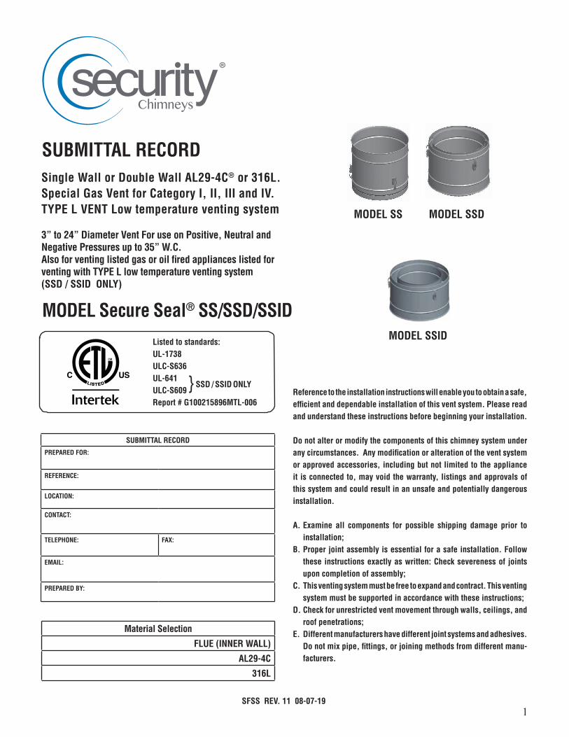
submittal record - security chimneys
TRANSCRIPT
1
3” to 24” Diameter Vent For use on Positive, Neutral and Negative Pressures up to 35” W.C.Also for venting listed gas or oil fired appliances listed for venting with TYPE L low temperature venting system(SSD / SSID ONLY)
MODEL Secure Seal® SS/SSD/SSID
Single Wall or Double Wall AL29-4C® or 316L. Special Gas Vent for Category I, II, III and IV. TYPE L VENT Low temperature venting system
SUBMITTAL RECORD
SFSS REV. 11 08-07-19
Reference to the installation instructions will enable you to obtain a safe, efficient and dependable installation of this vent system. Please read and understand these instructions before beginning your installation.
Do not alter or modify the components of this chimney system under any circumstances. Any modification or alteration of the vent system or approved accessories, including but not limited to the appliance it is connected to, may void the warranty, listings and approvals of this system and could result in an unsafe and potentially dangerous installation.
A. Examine all components for possible shipping damage prior to installation;
B. Proper joint assembly is essential for a safe installation. Follow these instructions exactly as written: Check severeness of joints upon completion of assembly;
C. This venting system must be free to expand and contract. This venting system must be supported in accordance with these instructions;
D. Check for unrestricted vent movement through walls, ceilings, and roof penetrations;
E. Different manufacturers have different joint systems and adhesives. Do not mix pipe, fittings, or joining methods from different manu-facturers.
Listed to standards:UL-1738ULC-S636UL-641ULC-S609Report # G100215896MTL-006
MODEL SS MODEL SSD
MODEL SSID
SUBMITTAL RECORD
PREPARED FOR:
REFERENCE:
LOCATION:
CONTACT:
TELEPHONE: FAX:
EMAIL:
PREPARED BY:
} SSD / SSID ONLY
Material Selection
FLUE (INNER WALL)
AL29-4C
316L
2
TABLE OF CONTENTS
Introduction ................................................................................. page 2
Testing / listing information ......................................................... page 2
Clearances to combustibles ......................................................... page 3
General installation requirements ................................................ page 3
Typical installations .................................................................... page 4-5
Chimney and fitting joint assembly .............................................. page 6
Chimney weight ........................................................................... page 6
Support methods and height ....................................................... page 7
Horizontal installation requirements ............................................ page 8
Maintain proper slope ................................................................. page 9
Vertical installation requirements ................................................ page 9
Wall penetration .......................................................................... page 10
Roof / floor penetration ............................................................... page 10
Condensate drains ...................................................................... page 10
Secure Seal as a liner .................................................................. page 12
Adjustable length ........................................................................ page 13
Secure Seal Flex .......................................................................... page 14
Maintenance instructions ............................................................. page 15
Secure Seal Labels ...................................................................... page 16
Warranty ...................................................................................... page 44
Product reference information ...................................................... page 48
INTRODUCTION
Secure Seal® single wall (SS) or double wall (SSD) or double wall insulated (SSID) is a special stainless steel vent system for gas fired appliances listed as Category I, II, III, and IV or in Canada as Type BH Gas Venting as noted in ULC-636, with a maximum operating temperature of 550 Degrees F (288 Degrees C), and a maximum rated positive pressure of 35” Water Column. It can also vent listed gas or oil fired appliance rated to be vent with TYPE L low temperature venting system (SSD & SSID only). Secure Seal must be installed by an experienced professional familiar with the operation and maintenance of heating appliances and venting. Before installing this product, examine all components for possible shipping damage and read the complete installation manual. Failure to follow proper installation procedures, including vent pitch and improper appliance connections, may cause unsafe conditions. Security Chimneys International Limited recommends the system to be inspected once a year by a qualified service technician
TESTING / LISTING INFORMATION
Security Chimney International, Ltd. Secure Seal model SS, SSD and SSID vent-ing system is listed with Intertek Testing Services (ETL) to UL/ULC standards:
U.S.A.• UL-1738 Special Gas Vent for Category I, II, III and IV appliances• UL-641 (SSD & SSID only) TYPE L VENT venting listed gas or oil burning appliances
CANADA• ULC-S636 Type BH Gas Vent Class I/II• ULC-S609 (SSD & SSID only) TYPE L VENT venting of flue gases with temperature not exceeding 300°C
from oil or gas burning appliances
This product must be installed in accordance with local building code require-ments as well as National codes: USA - National Fuel Gas code ANSI-Z223.1 or NFPA Standard 54, or NFPA 211. In CANADA - CAN/CGA-B149.1 or CAN/CGA-B149.2 Propane Installation Code as applicable.
3
CLEARANCES TO COMBUSTIBLES
Table 1 shows the required MINIMUM AIRSPACE CLEARANCE TO COMBUS-TIBLES. “Combustibles” include framing lumber, drywall, plywood, paneling, insulation, wiring and other building materials.
Minimum Clearance to Combustibles Single Wall SS
DiameterRated
operatingtemperature
Max. operating
temperature
Enclosed (4 sides)
Unenclosed (2 sides Max.)
Horiz. Vert. Horiz. Vert.
3” to 12” 480º F (250º C)
550º F (288º C) N/A N/A 2” 2”
14” to 24” 480º F(250º C)
550º F (288º C) N/A N/A 4” 4”
Minimum Clearance to Combustibles Double Wall SSD / SSID
DiameterRated
operatingtemperature
Max. operating
temperature
Enclosed (4 sides)
Unenclosed (2 sides Max.)
Horiz. Vert. Horiz. Vert.
3” to 12” 480º F (250º C)
550º F (288º C) N/A 1” 1” 1”
14” to 24” 480º F(250º C)
550º F (288º C) N/A 1” 3” 1”
3” to 12”L-VENT
480º F(250º C)
550º F (288º C) N/A 2” 2” 2”
14” to 24”
L-VENT
480º F(250º C)
550º F (288º C) N/A 2” 3” 2”
Table 1 - Minimum Clearances for Secure Seal®
Auxiliary parts such as combination Roof Supports, Roof Thimble, Flashings and Wall Thimble outer shields are intended to be attached directly to the framing or to ceilings, floors, or walls in accordance with their respective instructions. These parts, which are installed in contact with wood or other combustibles, are designed and tested to assure that they do not overheat at points of contact.
Notes:
1. Unenclosed requires at least two sides open.2. Single Wall (SS) may be enclosed only in non-combustible enclosure. 3. Reduced clearances may be attained by using non-combustible enclosures.4. Combustible Material is any material made of or surfaced with wood,
compressed paper, plant fibers or other materials that are capable of being ignited or burned. Such material shall be considered combustible even though it is flame-proofed, fire-retardant treated, or plastered. (Source: NFPA 54/ANSI Z223.1)
5. Design any enclosure to permit inspection of the system.6. Do not place insulation in any required clearance spaces surrounding the
vent system unless these instructions suggest otherwise and the insulation is specified or supplied.
7. When using Viton caulking, follow the manufactures required drying times.
GENERAL INSTALLATION REQUIREMENTS
When venting Category I, II, III, or IV appliances or TYPE L vented appliance, Secure Seal must be used for the entire length of the system. Do not mix pipe, fittings, or joining methods from different manufacturers. See the Secure Seal catalog for a complete list of parts and products. Every vent system must be planned and installed for optimum performance and safety. The venting system must be free to expand and contract and must be supported in accordance with these instructions. (Check for unrestricted vent movement through walls, ceilings, and roof penetrations). Refer to the gas appliance manufacturer’s instructions to determine venting requirements and limitations with respect to installation and use of the appliance. It is the responsibility of the installer to contact local building and fire officials concerning any installation restrictions and/or inspection requirements that may apply. Permits may be required before starting an installation.
• If required by the appliance manufacturer, a Drain Tee Cap must be located as close as possible to the appliance flue outlet. Depending on the arrangement of the vent, more than one drain may be required. Unless a Drain Tee Cap is supplied with the appliance, install a Secure Seal Drain Tee Cap.
• More than one Category II, III or IV appliance may not be connected into the same vent system, unless the appliance manufacturer specifically approved such a system and the appliance are designed for multiple venting. Cat. II, III or IV appliances MAY NOT be common vented with Cat. I, natural draft appliances. This limitation can be removed if an engineering analysis demonstrates normal and safe operation of appliances.
• Secure Seal must not come in contact with plumbing or electrical systems.• Maintain rated clearances to combustibles over the entire length of the
vent system.• Secure Seal shall not be routed into, through, or within any vent, such
as an existing masonry or factory-built chimney, that is connected to another appliance.
Material Thickness*all seams are laser welded
Secure Seal SS Secure Seal SSD / SSIDDiameter Flue Diameter Flue Casing
3” to 9”AL29-4C - .015”
316L - .015”3” to 9”
AL29-4C - .015”316L - .015”
441 stainless - .015”
10” to 16”AL29-4C - .020”
316L - .01910” to 16”
AL29-4C - .020”316L - .019”
441 stainless - .020”
18” to 24”AL29-4C - .024”
316L - .024”18” to 24”
AL29-4C - .024”316L - .024”
441 stainless - .024”
Material Code Designations
B Type 316 Stainless Steel
H Type 430 Stainless Steel
K Type 441 Stainless Steel
P Type 439 Stainless Steel
U Type AL29-4C Stainless Steel
PART NUMBERSThese instructions identify major model SS-SSD-SSID parts by name and part number.
Example:SSD 36” length with inside diameter 14” made of AL29-4C inner flue
and SS441 outer casting.
SS 30° elbow with inside diameter 22” made of 316L.
SSD wall support for 8” diameter chimney made of stainless 439.
SSD 14 L36 UK
Model Dia. Part Material
SS 22 E30 B
Model Dia. Part Material
SSD 8 WSHD P
Model Dia. Part Material

4
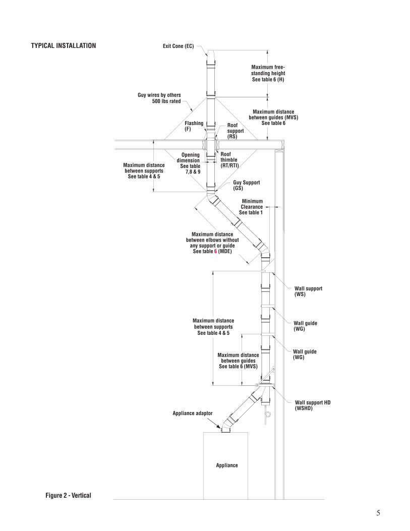
TYPICAL INSTALLATION
Cables, rods or braces By other500 lbs rated
Minimum slope1/4” per foot
Minimum ClearancesSee table 1
Maximum distance betweensupport (MHS), see table 6
30º Termination(STA)
Opening dimensionSee table 6
Wall Thimble(WT/WTI)
Roof Support (RS)
Suspension Band (SB)
Anchor Plate HD(APHD)
Appliance
Maximum distance suspended (S), see table 6
Figure 1 - Horizontal
Refer to condensate drain section for proper installation
Appliance adaptor
5
TYPICAL INSTALLATION Exit Cone (EC)
Guy wires by others500 lbs rated
Flashing(F)
Roofsupport(RS)
Guy Support(GS)
Wall guide(WG)
Wall guide(WG)
Wall support HD(WSHD)
Appliance
Wall support(WS)
Roofthimble(RT/RTI)
Maximum distancebetween guides (MVS)
See table 6
Opening dimension
See table 7,8 & 9
MinimumClearance
See table 1
Maximum distancebetween supports
See table 4 & 5
Maximum distancebetween elbows without
any support or guideSee table 6 (MDE)
Maximum distancebetween guides
See table 6 (MVS)
Maximum distancebetween supports
See table 4 & 5
Maximum free-standing heightSee table 6 (H)
Figure 2 - Vertical
Appliance adaptor
6
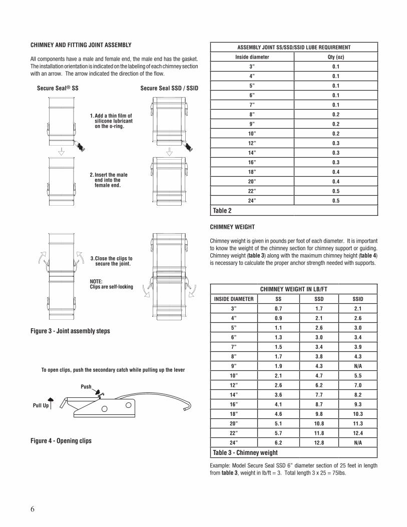
CHIMNEY AND FITTING JOINT ASSEMBLY
All components have a male and female end, the male end has the gasket. The installation orientation is indicated on the labeling of each chimney section with an arrow. The arrow indicated the direction of the flow.
CHIMNEY WEIGHT
Chimney weight is given in pounds per foot of each diameter. It is important to know the weight of the chimney section for chimney support or guiding. Chimney weight (table 3) along with the maximum chimney height (table 4) is necessary to calculate the proper anchor strength needed with supports.
1. Add a thin film of silicone lubricant on the o-ring.
2. Insert the male end into the female end.
3.Close the clips to secure the joint.
NOTE: Clips are self-locking
Figure 3 - Joint assembly steps
Figure 4 - Opening clips
Secure Seal® SS Secure Seal SSD / SSID
CHIMNEY WEIGHT IN LB/FT
INSIDE DIAMETER SS SSD SSID
3” 0.7 1.7 2.1
4” 0.9 2.1 2.6
5” 1.1 2.6 3.0
6” 1.3 3.0 3.4
7” 1.5 3.4 3.9
8” 1.7 3.8 4.3
9” 1.9 4.3 N/A
10” 2.1 4.7 5.5
12” 2.6 6.2 7.0
14” 3.6 7.7 8.2
16” 4.1 8.7 9.3
18” 4.6 9.8 10.3
20” 5.1 10.8 11.3
22” 5.7 11.8 12.4
24” 6.2 12.8 N/A
Table 3 - Chimney weight
Example: Model Secure Seal SSD 6” diameter section of 25 feet in length from table 3, weight in lb/ft = 3. Total length 3 x 25 = 75lbs.
ASSEMBLY JOINT SS/SSD/SSID LUBE REQUIREMENT
Inside diameter Qty (oz)
3” 0.1
4” 0.1
5” 0.1
6” 0.1
7” 0.1
8” 0.2
9” 0.2
10” 0.2
12” 0.3
14” 0.3
16” 0.3
18” 0.4
20” 0.4
22” 0.5
24” 0.5
Table 2
To open clips, push the secondary catch while pulling up the lever
Push
Pull Up
7
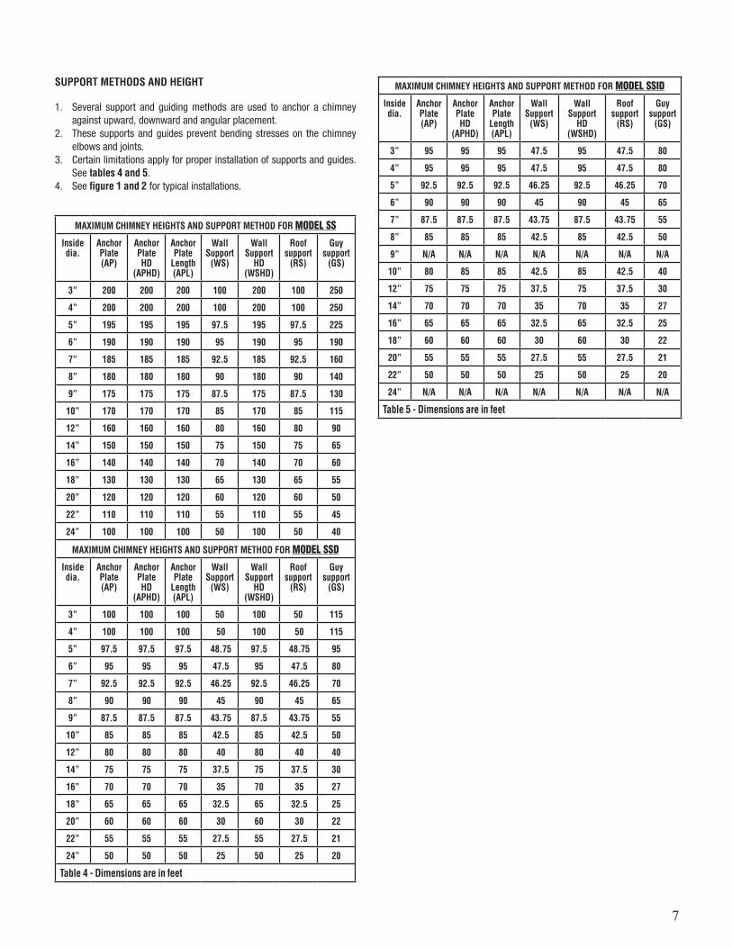
SUPPORT METHODS AND HEIGHT
1. Several support and guiding methods are used to anchor a chimney against upward, downward and angular placement.
2. These supports and guides prevent bending stresses on the chimney elbows and joints.
3. Certain limitations apply for proper installation of supports and guides. See tables 4 and 5.
4. See figure 1 and 2 for typical installations.
MAXIMUM CHIMNEY HEIGHTS AND SUPPORT METHOD FOR MODEL SS
Inside dia.
Anchor Plate (AP)
Anchor Plate HD
(APHD)
Anchor Plate
Length (APL)
Wall Support
(WS)
Wall Support
HD (WSHD)
Roof support
(RS)
Guy support
(GS)
3” 200 200 200 100 200 100 250
4” 200 200 200 100 200 100 250
5” 195 195 195 97.5 195 97.5 225
6” 190 190 190 95 190 95 190
7” 185 185 185 92.5 185 92.5 160
8” 180 180 180 90 180 90 140
9” 175 175 175 87.5 175 87.5 130
10” 170 170 170 85 170 85 115
12” 160 160 160 80 160 80 90
14” 150 150 150 75 150 75 65
16” 140 140 140 70 140 70 60
18” 130 130 130 65 130 65 55
20” 120 120 120 60 120 60 50
22” 110 110 110 55 110 55 45
24” 100 100 100 50 100 50 40
MAXIMUM CHIMNEY HEIGHTS AND SUPPORT METHOD FOR MODEL SSD
Inside dia.
Anchor Plate (AP)
Anchor Plate HD
(APHD)
Anchor Plate
Length (APL)
Wall Support
(WS)
Wall Support
HD (WSHD)
Roof support
(RS)
Guy support
(GS)
3” 100 100 100 50 100 50 115
4” 100 100 100 50 100 50 115
5” 97.5 97.5 97.5 48.75 97.5 48.75 95
6” 95 95 95 47.5 95 47.5 80
7” 92.5 92.5 92.5 46.25 92.5 46.25 70
8” 90 90 90 45 90 45 65
9” 87.5 87.5 87.5 43.75 87.5 43.75 55
10” 85 85 85 42.5 85 42.5 50
12” 80 80 80 40 80 40 40
14” 75 75 75 37.5 75 37.5 30
16” 70 70 70 35 70 35 27
18” 65 65 65 32.5 65 32.5 25
20” 60 60 60 30 60 30 22
22” 55 55 55 27.5 55 27.5 21
24” 50 50 50 25 50 25 20
Table 4 - Dimensions are in feet
MAXIMUM CHIMNEY HEIGHTS AND SUPPORT METHOD FOR MODEL SSID
Inside dia.
Anchor Plate (AP)
Anchor Plate HD
(APHD)
Anchor Plate
Length (APL)
Wall Support
(WS)
Wall Support
HD (WSHD)
Roof support
(RS)
Guy support
(GS)
3” 95 95 95 47.5 95 47.5 80
4” 95 95 95 47.5 95 47.5 80
5” 92.5 92.5 92.5 46.25 92.5 46.25 70
6” 90 90 90 45 90 45 65
7” 87.5 87.5 87.5 43.75 87.5 43.75 55
8” 85 85 85 42.5 85 42.5 50
9” N/A N/A N/A N/A N/A N/A N/A
10” 80 85 85 42.5 85 42.5 40
12” 75 75 75 37.5 75 37.5 30
14” 70 70 70 35 70 35 27
16” 65 65 65 32.5 65 32.5 25
18” 60 60 60 30 60 30 22
20” 55 55 55 27.5 55 27.5 21
22” 50 50 50 25 50 25 20
24” N/A N/A N/A N/A N/A N/A N/A
Table 5 - Dimensions are in feet
8
Figure 5 - Position of support
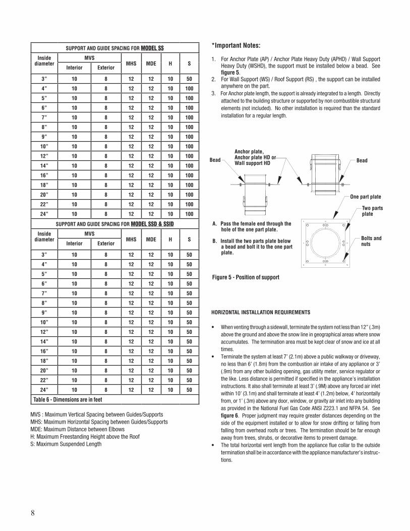
*Important Notes:
1. For Anchor Plate (AP) / Anchor Plate Heavy Duty (APHD) / Wall Support Heavy Duty (WSHD), the support must be installed below a bead. See figure 5.
2. For Wall Support (WS) / Roof Support (RS) , the support can be installed anywhere on the part.
3. For Anchor plate length, the support is already integrated to a length. Directly attached to the building structure or supported by non combustible structural elements (not included). No other installation is required than the standard installation for a regular length.
Anchor plate,Anchor plate HD or Wall support HD
A. Pass the female end through the hole of the one part plate.
B. Install the two parts plate below a bead and bolt it to the one part plate.
Bead Bead
Bolts and nuts
Two parts plate
One part plate
HORIZONTAL INSTALLATION REQUIREMENTS
• When venting through a sidewall, terminate the system not less than 12” (.3m) above the ground and above the snow line in geographical areas where snow accumulates. The termination area must be kept clear of snow and ice at all times.
• Terminate the system at least 7’ (2.1m) above a public walkway or driveway, no less than 6’ (1.8m) from the combustion air intake of any appliance or 3’ (.9m) from any other building opening, gas utility meter, service regulator or the like. Less distance is permitted if specified in the appliance’s installation instructions. It also shall terminate at least 3’ (.9M) above any forced air inlet within 10’ (3.1m) and shall terminate at least 4’ (1.2m) below, 4’ horizontally from, or 1’ (.3m) above any door, window, or gravity air inlet into any building as provided in the National Fuel Gas Code ANSI Z223.1 and NFPA 54. See figure 6. Proper judgment may require greater distances depending on the side of the equipment installed or to allow for snow drifting or falling from falling from overhead roofs or trees. The termination should be far enough away from trees, shrubs, or decorative items to prevent damage.
• The total horizontal vent length from the appliance flue collar to the outside termination shall be in accordance with the appliance manufacturer’s instruc-tions.
SUPPORT AND GUIDE SPACING FOR MODEL SS
Inside diameter
MVSMHS MDE H S
Interior Exterior
3” 10 8 12 12 10 50
4” 10 8 12 12 10 100
5” 10 8 12 12 10 100
6” 10 8 12 12 10 100
7” 10 8 12 12 10 100
8” 10 8 12 12 10 100
9” 10 8 12 12 10 100
10” 10 8 12 12 10 100
12” 10 8 12 12 10 100
14” 10 8 12 12 10 100
16” 10 8 12 12 10 100
18” 10 8 12 12 10 100
20” 10 8 12 12 10 100
22” 10 8 12 12 10 100
24” 10 8 12 12 10 100
SUPPORT AND GUIDE SPACING FOR MODEL SSD & SSID
Inside diameter
MVSMHS MDE H S
Interior Exterior
3” 10 8 12 12 10 50
4” 10 8 12 12 10 50
5” 10 8 12 12 10 50
6” 10 8 12 12 10 50
7” 10 8 12 12 10 50
8” 10 8 12 12 10 50
9” 10 8 12 12 10 50
10” 10 8 12 12 10 50
12” 10 8 12 12 10 50
14” 10 8 12 12 10 50
16” 10 8 12 12 10 50
18” 10 8 12 12 10 50
20” 10 8 12 12 10 50
22” 10 8 12 12 10 50
24” 10 8 12 12 10 50
Table 6 - Dimensions are in feet
MVS : Maximum Vertical Spacing between Guides/SupportsMHS: Maximum Horizontal Spacing between Guides/SupportsMDE: Maximum Distance between ElbowsH: Maximum Freestanding Height above the RoofS: Maximum Suspended Length
9
7 ft above public walkways and drives
1 ft. above doors and windows
4 ft below any window or fresh air inlet
1 ft. above ground or snow line
Sidewalk
Figure 6 - Horizontal termination requirements
MAINTAIN PROPER SLOPE
• Install with a continuous 1/4” per foot (minimum) slope, as is required by the National Fuel Gas Code for all gas-fired appliances.
• Vent systems for condensing appliances must have a continuous 1/4” per foot (minimum) slope toward the appliance or a condensate drain. Always check the appliance manufacturer’s instructions for proper drain requirements.
• Secure Seal® offers a range of tees and elbows that are built incorporating a 2 degree slope, we recommend that you use these to generate your slope.
• Some appliances require the venting system to be sloped toward the horizontal termination.
• Remember, if you raise the appliance or lower the ceiling you must adjust the slope of the vent to maintain the 1/4” per foot minimum.
4 ft. horizontally from door and windows
Figure 7 - Vertical installation requirements
VERTICAL INSTALLATION REQUIREMENTS
1. The vent system must terminate at least 3 feet above the roof line and at least 2 feet higher than any portion of the building within 10 feet. See figure 7. This limitation can be removed if an engineering analysis demonstrates normal and safe operation of appliance.
2. When terminated at a height of more than 10 feet, the stack must be supported by a Guy Section.
3. The vent system must terminate with one of the Secure Seal® terminations.
Except; a) Category I appliances (natural draft) must use a Rain Cap. It is optional
on Category II. This limitation can be removed if an engineering analysis demonstrates normal and safe operation of appliance.
b) Vent systems without provisions for draining rain water must use a Rain Cap.
c) Terminations or approved mechanical vent devices specified or provided by the appliance manufacturer are permitted.
4. The total continuous distance of the vent system from the appliance flue collar to the termination shall not exceed that specified in the appliance manufacturer’s installation instructions. When venting natural draft ap-pliances the termination must be at least 5 feet above the topmost draft hood. Otherwise a listed mechanical draft inducing device is required. This limitation can be removed if an engineering analysis demonstrates normal and safe operation of appliance.
5. In general, systems installed in cold climates perform best, and conden-sation is reduced, when the system is fully enclosed by some part of the building structure or by using insulated SSID venting system.
6. In cold climates do not install a condensate drain on the exterior of the building. Doing so may result in dangerous icy conditions on surfaces near the drain and may cause damage to the vent system and/or the building exterior. Security Chimneys will NOT be held liable for any personal injury or property damage due to any formation of ice.
7. Vertical supports are required after every transition to vertical. Vertical supports are also required after every offset elbow.
8. Unless Secure Seal is installed in a fire rated shaft, a roof thimble and support is required when penetration fire rated floors, walls or ceilings.
10’
2’
2 ft. above structures within 10 ft.
10
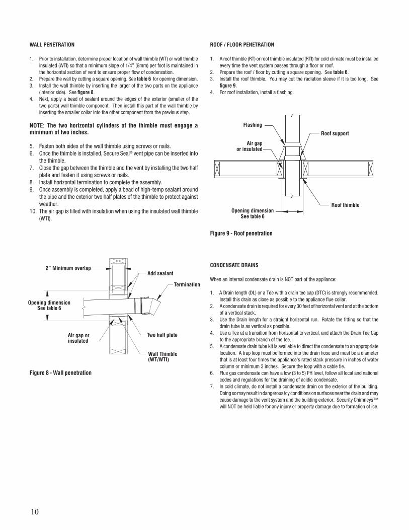
ROOF / FLOOR PENETRATION
1. A roof thimble (RT) or roof thimble insulated (RTI) for cold climate must be installed every time the vent system passes through a floor or roof.
2. Prepare the roof / floor by cutting a square opening. See table 6. 3. Install the roof thimble. You may cut the radiation sleeve if it is too long. See
figure 9.4. For roof installation, install a flashing.
Roof support
Roof thimbleOpening dimension
See table 6
Air gap or insulated
Flashing
CONDENSATE DRAINS
When an internal condensate drain is NOT part of the appliance:
1. A Drain length (DL) or a Tee with a drain tee cap (DTC) is strongly recommended. Install this drain as close as possible to the appliance flue collar.
2. A condensate drain is required for every 30 feet of horizontal vent and at the bottom of a vertical stack.
3. Use the Drain length for a straight horizontal run. Rotate the fitting so that the drain tube is as vertical as possible.
4. Use a Tee at a transition from horizontal to vertical, and attach the Drain Tee Cap to the appropriate branch of the tee.
5. A condensate drain tube kit is available to direct the condensate to an appropriate location. A trap loop must be formed into the drain hose and must be a diameter that is at least four times the appliance’s rated stack pressure in inches of water column or minimum 3 inches. Secure the loop with a cable tie.
6. Flue gas condensate can have a low (3 to 5) PH level, follow all local and national codes and regulations for the draining of acidic condensate.
7. In cold climate, do not install a condensate drain on the exterior of the building. Doing so may result in dangerous icy conditions on surfaces near the drain and may cause damage to the vent system and the building exterior. Security Chimneys™ will NOT be held liable for any injury or property damage due to formation of ice.
Figure 8 - Wall penetration
WALL PENETRATION
1. Prior to installation, determine proper location of wall thimble (WT) or wall thimble insulated (WTI) so that a minimum slope of 1/4” (6mm) per foot is maintained in the horizontal section of vent to ensure proper flow of condensation.
2. Prepare the wall by cutting a square opening. See table 6 for opening dimension.3. Install the wall thimble by inserting the larger of the two parts on the appliance
(interior side). See figure 8.4. Next, apply a bead of sealant around the edges of the exterior (smaller of the
two parts) wall thimble component. Then install this part of the wall thimble by inserting the smaller collar into the other component from the previous step.
NOTE: The two horizontal cylinders of the thimble must engage a minimum of two inches.
5. Fasten both sides of the wall thimble using screws or nails.6. Once the thimble is installed, Secure Seal® vent pipe can be inserted into
the thimble.7. Close the gap between the thimble and the vent by installing the two half
plate and fasten it using screws or nails.8. Install horizontal termination to complete the assembly.9. Once assembly is completed, apply a bead of high-temp sealant around
the pipe and the exterior two half plates of the thimble to protect against weather.
10. The air gap is filled with insulation when using the insulated wall thimble (WTI).
Add sealant
Termination
Two half plate
Wall Thimble(WT/WTI)
Air gap or insulated
Opening dimensionSee table 6
2” Minimum overlap
Figure 9 - Roof penetration
11
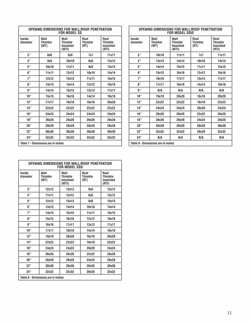
OPENING DIMENSIONS FOR WALL/ROOF PENETRATIONFOR MODEL SS
Inside diameter
Wall Thimble (WT)
Wall Thimble Insulated (WTI)
Roof Thimble (RT)
Roof Thimble Insulated (RTI)
3” 8x8 9x9 7x7 11x11
4” 9x9 10x10 8x8 12x12
5” 10x10 11x11 9x9 13x13
6” 11x11 12x12 10x10 14x14
7” 12x12 13x13 11x11 15x15
8” 13x13 14x14 12x12 16x16
9” 14x14 15x15 13x13 17x17
10” 15x15 16x16 14x14 18x18
12” 17x17 18x18 16x16 20x20
14” 22x22 22x22 22x22 22x22
16” 24x24 24x24 24x24 24x24
18” 26x26 26x26 26x26 26x26
20” 28x28 28x28 28x28 28x28
22” 30x30 30x30 30x30 30x30
24” 32x32 32x32 32x32 32x32
Table 7 - Dimensions are in inches
OPENING DIMENSIONS FOR WALL/ROOF PENETRATIONFOR MODEL SSID
Inside diameter
Wall Thimble (WT)
Wall Thimble Insulated (WTI)
Roof Thimble (RT)
Roof Thimble Insulated (RTI)
3” 10x10 11x11 7x7 11x11
4” 13x13 14x14 10x10 14x14
5” 14x14 15x15 11x11 15x15
6” 15x15 16x16 12x12 16x16
7” 16x16 17x17 13x13 17x17
8” 17x17 18x18 14x14 18x18
9” N/A N/A N/A N/A
10” 19x19 20x20 16x16 20x20
12” 22x22 22x22 18x18 22x22
14” 24x24 24x24 20x20 24x24
16” 26x26 26x26 22x22 26x26
18” 28x28 28x28 24x24 28x28
20” 30x30 30x30 26x26 30x30
22” 32x32 32x32 28x28 32x32
24” N/A N/A N/A N/A
Table 9 - Dimensions are in inches
OPENING DIMENSIONS FOR WALL/ROOF PENETRATIONFOR MODEL SSD
Inside diameter
Wall Thimble (WT)
Wall Thimble Insulated (WTI)
Roof Thimble (RT)
Roof Thimble Insulated (RTI)
3” 12x12 13x13 9x9 13x13
4” 11x11 12x12 8x8 12x12
5” 12x12 13x13 9x9 13x13
6” 13x13 14x14 10x10 14x14
7” 14x14 15x15 11x11 15x15
8” 15x15 16x16 12x12 16x16
9” 16x16 17x17 13x13 17x17
10” 17x17 18x18 14x14 18x18
12” 19x19 20x20 16x16 20x20
14” 22x22 22x22 18x18 22x22
16” 24x24 24x24 20x20 24x24
18” 26x26 26x26 22x22 26x26
20” 28x28 28x28 24x24 28x28
22” 30x30 30x30 26x26 30x30
24” 32x32 32x32 28x28 32x32
Table 8 - Dimensions are in inches
12
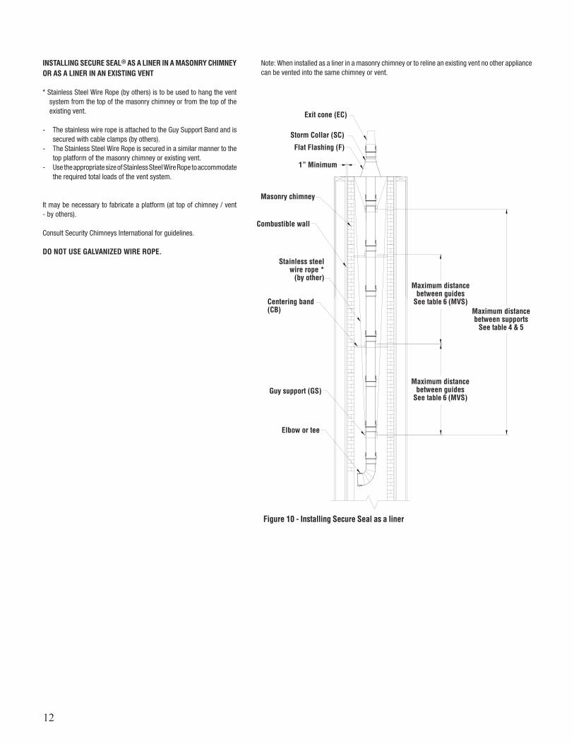
INSTALLING SECURE SEAL® AS A LINER IN A MASONRY CHIMNEY OR AS A LINER IN AN EXISTING VENT
* Stainless Steel Wire Rope (by others) is to be used to hang the vent system from the top of the masonry chimney or from the top of the existing vent.
- The stainless wire rope is attached to the Guy Support Band and is secured with cable clamps (by others).
- The Stainless Steel Wire Rope is secured in a similar manner to the top platform of the masonry chimney or existing vent.
- Use the appropriate size of Stainless Steel Wire Rope to accommodate the required total loads of the vent system.
It may be necessary to fabricate a platform (at top of chimney / vent - by others).
Consult Security Chimneys International for guidelines.
DO NOT USE GALVANIZED WIRE ROPE.
Note: When installed as a liner in a masonry chimney or to reline an existing vent no other appliance can be vented into the same chimney or vent.
Exit cone (EC)
1” Minimum
Masonry chimney
Combustible wall
Centering band (CB)
Guy support (GS)Maximum distance
between guides See table 6 (MVS)
Maximum distance between guides
See table 6 (MVS)
Elbow or tee
Stainless steel wire rope *
(by other)
Maximum distance between supports
See table 4 & 5
Storm Collar (SC)
Flat Flashing (F)
Figure 10 - Installing Secure Seal as a liner
13
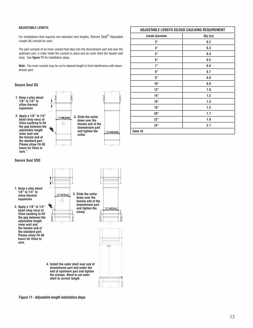
ADJUSTABLE LENGTH
For installations that requires non-standard vent lengths, Secure Seal® Adjustable Length (AL) should be used.
The part consists of an inner conduit that slips into the downstream part and over the upstream part, a collar holds the conduit in place and an outer shell (for double wall only). See figure 11 for installation steps.
Note: The inner conduit may be cut to desired length to limit interference with down-stream part.
1. Keep a play about 1/8” to 1/4” to allow thermal expansion
1. Keep a play about 1/8” to 1/4” to allow thermal expansion
2. Apply a 1/8” to 1/4” bead (may vary) of Viton caulking to fill the gap between the adjustable length inner wall and the female end of the standard part. Please allow 24-36 hours for Viton to cure.”
2. Apply a 1/8” to 1/4” bead (may vary) of Viton caulking to fill the gap between the adjustable length inner wall and the female end of the standard part. Please allow 24-36 hours for Viton to cure.
3. Slide the collar down over the female end of the downstream part and tighten the collar
3. Slide the collar down over the female end of the downstream part and tighten the clamp
4. Install the outer shell over end of downstream part and under the end of upstream part and tighten the clamps. Need to cut outer shell to correct length.
ADJUSTABLE LENGTH SS/SSD CAULKING REQUIREMENT
Inside diameter Qty (oz)
3” 0.2
4” 0.3
5” 0.4
6” 0.5
7” 0.6
8” 0.7
9” 0.8
10” 0.9
12” 1.0
14” 1.2
16” 1.4
18” 1.5
20” 1.7
22” 1.9
24” 2.1
Table 10
Figure 11 - Adjustable length installation steps
Secure Seal SS
Secure Seal SSD
14
SECURE SEAL FLEX
*IMPORTANT NOTE
When installing Secure Seal Flex, the direction of exhaust flow is always from the appliance. There is an arrow printed on each section of liner and component that will point in the direction of the exhaust gas. If the inner liner is installed correctly the proper direction can be determined by running your fingernails up the inside wall of the liner. If the direction is correct, your nails will catch at the seams of the inner wall. If it is incorrect, your nails will slide smoothly across the inner surface.
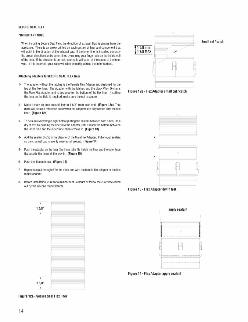
Attaching adapters to SECURE SEAL FLEX liner
1- The adapter without the latches is the Female Flex Adapter and designed for the top of the flex liner. The Adapter with the latches and the black Viton O-ring is the Male Flex Adapter and is designed for the bottom of the flex liner. If cutting the liner on the field is required, make sure the cut is square.
2- Make a mark on both ends of liner at 1 5/8” from each end. (Figure 12a) That mark will act as a reference point when the adapters are fully seated onto the flex liner. (Figure 12b)
3- To be sure everything is right before putting the sealant between both tubes, do a dry fit test by pushing the liner into the adapter until it reach the bottom between the inner tube and the outer tube, then remove it. (Figure 13)
4- Add the sealant S-650 in the channel of the Male Flex Adapter. Put enough sealant so the channel gap is evenly covered all around. (Figure 14)
5- Push the adapter on the liner (the inner tube fits inside the liner and the outer tube fits outside the liner) all the way in. (Figure 15)
6- Push the little natches. (Figure 16)
7- Repeat steps 3 through 6 for the other end with the female flex adapter or the flex to flex adapter.
8- Before installation, cure for a minimum of 24 hours or follow the cure time called out by the silicone manufacturer.
Figure 14 - Flex Adapter apply sealant
apply sealant
Figure 12a - Secure Seal Flex liner
1 5/8”
1 5/8”
Figure 12b - Flex Adapter small cut / catch
Small cut / catch
1 5/8 min1 7/8 MAX
Figure 13 - Flex Adapter dry fit test
15
MAINTENANCE INSTRUCTIONS
As with all vents, the Secure Seal vent system should be inspected at least annually for the presence of deposits or debris and any accumulation should be removed. The vent system should also be inspected at regular periods for signs of leakage of condensate or combustion products at any joints.
If the vent system incorporates a drain hose from either a Drain length or a Drain tee cap, the hose must be inspected periodically to ensure that water is in the trap loop. If a proper trap loop is not maintained, exhaust from the connected appliances may accumulate in the building area.
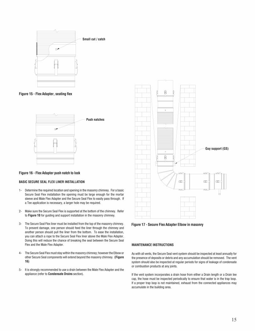
BASIC SECURE SEAL FLEX LINER INSTALLATION
1- Determine the required location and opening in the masonry chimney. For a basic Secure Seal Flex installation the opening must be large enough for the mortar sleeve and Male Flex Adapter and the Secure Seal Flex to easily pass through. If a Tee application is necessary, a larger hole may be required.
2- Make sure the Secure Seal Flex is supported at the bottom of the chimney. Refer to Figure 10 for guiding and support installation in the masonry chimney.
3- The Secure Seal Flex liner must be installed from the top of the masonry chimney. To prevent damage, one person should feed the liner through the chimney and another person should pull the liner from the bottom. To ease the installation, you can attach a rope to the Secure Seal Flex liner above the Male Flex Adapter. Doing this will reduce the chance of breaking the seal between the Secure Seal Flex and the Male Flex Adapter.
4- The Secure Seal Flex must stay within the masonry chimney; however the Elbow or other Secure Seal components will extend beyond the masonry chimney. (Figure 16)
5- It is strongly recommended to use a drain between the Male Flex Adapter and the appliance (refer to Condensate Drains section).
Figure 17 - Secure Flex Adapter Elbow in masonry
Figure 15 - Flex Adapter, seating flex
Small cut / catch
Push natches
Figure 16 - Flex Adapter push natch to lock
Guy support (GS)
16
SS, SSD / SSID SECURE SEAL® CHIMNEY LABELS
The labels supplied for product identification are shown here and indicates the flow of the flue gases in the venting system.
17
SSD / SSID VENT LENGTHS
SSD & SSID Lengths
Ø (in.)
Effective Length(in.)
Product CodeSSD
Product CodeSSID
3 to 24 6-5/8 SSDØL9 SSIDØL9
3 to 24 9-5/8 SSDØL12 SSIDØL12
3 to 24 15-5/8 SSDØL18 SSIDØL18
3 to 24 21-5/8 SSDØL24 SSIDØL24
3 to 24 33-5/8 SSDØL36 SSIDØL36
SSD & SSID Adjustable Lengths
Ø(in.)
Effective Length(in.)
Product CodeSSD
Product CodeSSID
3 to 24 3 to 5 SSDØAL9 SSIDØAL9
3 to 24 3 to 14 SSDØAL18 SSIDØAL18
SSD & SSID Test Port Lengths
Ø(in.)
Effective Length(in.)
Product CodeSSD
Product CodeSSID
3to 24 6-5/8 SSDØTPL SSIDØTPL
Drain Ø4–Ø24, 1/4 NPT, 1/2 O.D.
SSD & SSID Drain Lengths
Ø (in.) Effective Length (in.)
Product CodeSSD
Product CodeSSID
KFactor
3 to 24 6-5/8 SSDØDL SSIDØDL 0.25
Drain Ø4–Ø10, 1/4 NPT, 1/2 O.D.Drain 12–Ø24, 1/2 NPT, 5/8 O.D.
Figure 18
Figure 19
Figure 20
Figure 21
Effectivelength
Effectivelength
3-5/8”
Ø
Ø
Effectivelength
Effectivelength
3-1/4ӯ
Ø
NOTE: SSID 9” and 24” not available.
NOTE: SSID 9” and 24” not available.
NOTE: SSID 9” and 24” not available.
NOTE: SSID 9” and 24” not available.
Ø
EFFECTIVELENGTH
MAX
SSD Telescopic Lengths
Ø (in.) Effective Length (in.) Product Code
3 to 24 14 to 20 SSDØLAT20
3 to 24 20 to 32 SSDØLAT32
Figure 21a
NOTE: SSID 3”, 9” and 24” not available.
18
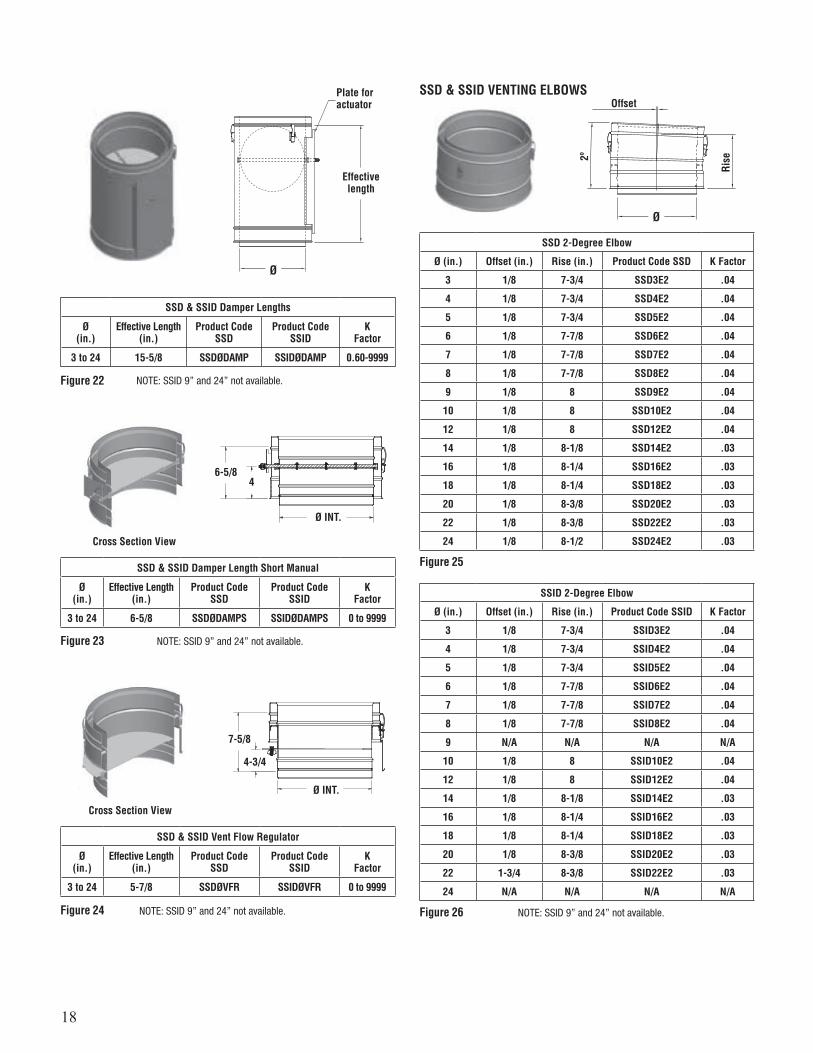
SSD & SSID VENTING ELBOWS
SSD & SSID Damper Lengths
Ø(in.)
Effective Length(in.)
Product CodeSSD
Product CodeSSID
KFactor
3 to 24 15-5/8 SSDØDAMP SSIDØDAMP 0.60-9999
SSD & SSID Damper Length Short Manual
Ø(in.)
Effective Length(in.)
Product CodeSSD
Product CodeSSID
KFactor
3 to 24 6-5/8 SSDØDAMPS SSIDØDAMPS 0 to 9999
SSD & SSID Vent Flow Regulator
Ø(in.)
Effective Length(in.)
Product CodeSSD
Product CodeSSID
KFactor
3 to 24 5-7/8 SSDØVFR SSIDØVFR 0 to 9999
SSD 2-Degree Elbow
Ø (in.) Offset (in.) Rise (in.) Product Code SSD K Factor
3 1/8 7-3/4 SSD3E2 .04
4 1/8 7-3/4 SSD4E2 .04
5 1/8 7-3/4 SSD5E2 .04
6 1/8 7-7/8 SSD6E2 .04
7 1/8 7-7/8 SSD7E2 .04
8 1/8 7-7/8 SSD8E2 .04
9 1/8 8 SSD9E2 .04
10 1/8 8 SSD10E2 .04
12 1/8 8 SSD12E2 .04
14 1/8 8-1/8 SSD14E2 .03
16 1/8 8-1/4 SSD16E2 .03
18 1/8 8-1/4 SSD18E2 .03
20 1/8 8-3/8 SSD20E2 .03
22 1/8 8-3/8 SSD22E2 .03
24 1/8 8-1/2 SSD24E2 .03
SSID 2-Degree Elbow
Ø (in.) Offset (in.) Rise (in.) Product Code SSID K Factor
3 1/8 7-3/4 SSID3E2 .04
4 1/8 7-3/4 SSID4E2 .04
5 1/8 7-3/4 SSID5E2 .04
6 1/8 7-7/8 SSID6E2 .04
7 1/8 7-7/8 SSID7E2 .04
8 1/8 7-7/8 SSID8E2 .04
9 N/A N/A N/A N/A
10 1/8 8 SSID10E2 .04
12 1/8 8 SSID12E2 .04
14 1/8 8-1/8 SSID14E2 .03
16 1/8 8-1/4 SSID16E2 .03
18 1/8 8-1/4 SSID18E2 .03
20 1/8 8-3/8 SSID20E2 .03
22 1-3/4 8-3/8 SSID22E2 .03
24 N/A N/A N/A N/A
Figure 22
Figure 23
Figure 24
Figure 25
Figure 26
Effectivelength
Plate for actuator
Ø
Offset
Rise2º
Ø
Cross Section View
Cross Section View
Ø INT.
Ø INT.
6-5/8
7-5/8
4-3/4
4
NOTE: SSID 9” and 24” not available.
NOTE: SSID 9” and 24” not available.
NOTE: SSID 9” and 24” not available.NOTE: SSID 9” and 24” not available.

19
SSD 15-Degree Elbow
Ø (in.) Offset (in.) Rise (in.) Product Code SSD K Factor
3 1 8-3/4 SSD3E15 .31
4 1 8-3/4 SSD4E15 .31
5 1 8-3/4 SSD5E15 .30
6 1-1/8 9 SSD6E15 .30
7 1-1/8 9-3/8 SSD7E15 .29
8 1-1/4 9-5/8 SSD8E15 .29
9 1-1/4 9-7/8 SSD9E15 .28
10 1-1/4 10-1/8 SSD10E15 .28
12 1-3/8 10-5/8 SSD12E15 .27
14 1-3/8 11-1/8 SSD14E15 .27
16 1-1/2 11-5/8 SSD16E15 .26
18 1-1/2 12-1/8 SSD18E15 .26
20 1-5/8 12-5/8 SSD20E15 .26
22 1-5/8 13-1/4 SSD22E15 .26
24 1-3/4 13-3/4 SSD24E15UK .26
Figure 27
Offset
Rise15
ºØ
SSID 15-Degree Elbow
Ø (in.) Offset (in.) Rise (in.) Product Code SSID K Factor
3 1-1/8 9 SSID3E15UK .31
4 1-1/8 9 SSID4E15UK .31
5 1-1/8 9-3/8 SSID5E15UK .30
6 1-1/4 9-5/8 SSID6E15UK .30
7 1-1/4 9-7/8 SSID7E15UK .29
8 1-1/4 10-1/8 SSID8E15UK .29
9 N/A N/A N/A N/A
10 1-3/8 10-5/8 SSID10E15UK .28
12 1-3/8 11-1/8 SSID12E15UK .27
14 1-1/2 11-5/8 SSID14E15UK .27
16 1-1/2 12-1/8 SSID16E15UK .26
18 1-5/8 12-5/8 SSID18E15UK .26
20 1-5/8 13-1/4 SSID20E15UK .26
22 1-3/4 13-3/4 SSID22E15UK .26
24 N/A N/A N/A N/A
Figure 28
SSD 30-Degree Elbow
Ø (in.) Offset (in.) Rise (in.) Product Code SSD K Factor
3 2-3/8 9-5/8 SSD3E30 .61
4 2-3/8 9-5/8 SSD4E30 .61
5 2-3/8 9-5/8 SSD5E30 .60
6 2-5/8 10-1/8 SSD6E30 .59
7 2-3/4 10-5/8 SSD7E30 .58
8 2-7/8 11-1/8 SSD8E30 .57
9 3 11-5/8 SSD9E30 .56
10 3-1/8 12-1/8 SSD10E30 .55
12 3-3/8 13-1/8 SSD12E30 .54
14 3-5/8 14-1/8 SSD14E30 .54
16 3-7/8 15-1/8 SSD16E30 .53
18 4-1/8 16-1/8 SSD18E30 .52
20 4-1/2 17-1/8 SSD20E30 .52
22 4-3/4 18-1/8 SSD22E30 .51
24 5 19-1/8 SSD24E30UK .51
SSID 30-Degree Elbow
Ø (in.) Offset (in.) Rise (in.) Product Code SSID K Factor
3 2-5/8 10-1/8 SSID3E30UK 0.61
4 2-5/8 10-1/8 SSID4E30UK 0.61
5 2-3/4 10-5/8 SSID5E30UK 0.60
6 2-7/8 11-1/8 SSID6E30UK 0.59
7 3 11-5/8 SSID7E30UK 0.58
8 3-1/8 12-1/8 SSID8E30UK 0.57
9 N/A N/A N/A N/A
10 3-3/8 13-1/8 SSID10E30UK 0.55
12 3-5/8 14-1/8 SSID12E30UK 0.54
14 3-7/8 15-1/8 SSID14E30UK 0.54
16 4-1/8 16-1/8 SSID16E30UK 0.53
18 4-1/2 17-1/8 SSID18E30UK 0.52
20 4-3/4 18-1/8 SSID20E30UK 0.52
22 5 19-1/8 SSID22E30UK 0.51
24 N/A N/A N/A N/A
Figure 29
Figure 30
Offset
30º
Ø
Rise
NOTE: SSID 9” and 24” not available.NOTE: SSID 9” and 24” not available.
20
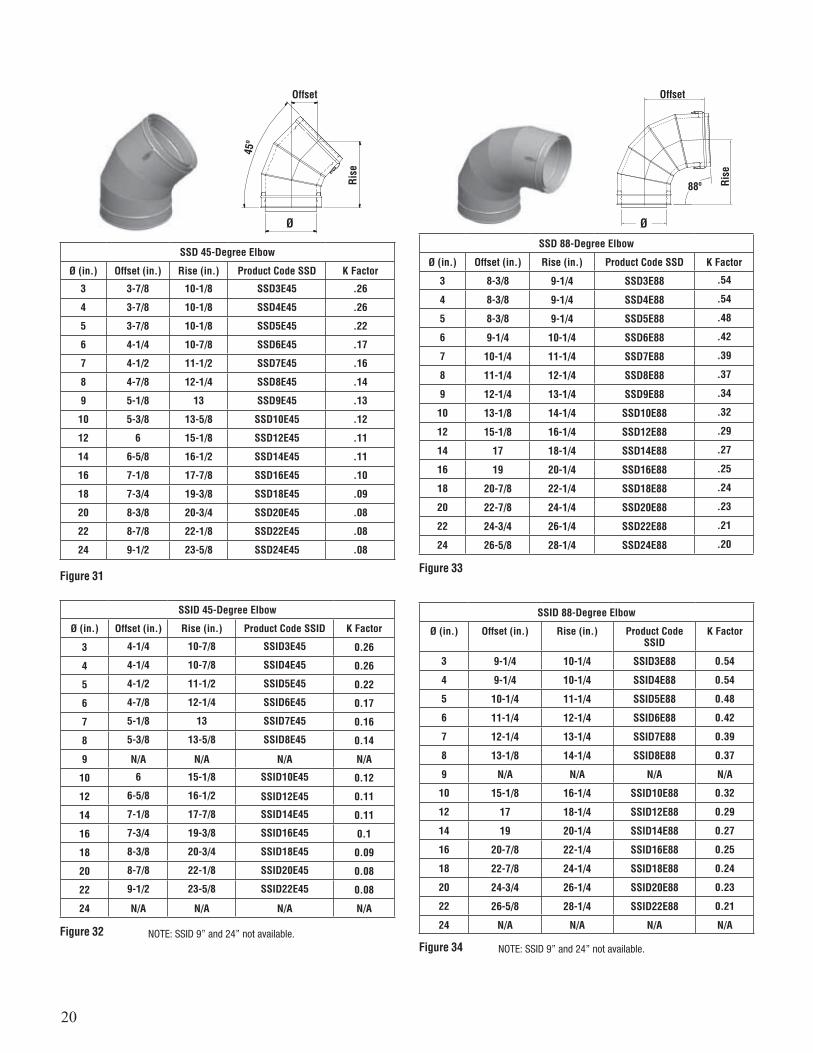
SSD 45-Degree Elbow
Ø (in.) Offset (in.) Rise (in.) Product Code SSD K Factor
3 3-7/8 10-1/8 SSD3E45 .26
4 3-7/8 10-1/8 SSD4E45 .26
5 3-7/8 10-1/8 SSD5E45 .22
6 4-1/4 10-7/8 SSD6E45 .17
7 4-1/2 11-1/2 SSD7E45 .16
8 4-7/8 12-1/4 SSD8E45 .14
9 5-1/8 13 SSD9E45 .13
10 5-3/8 13-5/8 SSD10E45 .12
12 6 15-1/8 SSD12E45 .11
14 6-5/8 16-1/2 SSD14E45 .11
16 7-1/8 17-7/8 SSD16E45 .10
18 7-3/4 19-3/8 SSD18E45 .09
20 8-3/8 20-3/4 SSD20E45 .08
22 8-7/8 22-1/8 SSD22E45 .08
24 9-1/2 23-5/8 SSD24E45 .08
SSID 45-Degree Elbow
Ø (in.) Offset (in.) Rise (in.) Product Code SSID K Factor
3 4-1/4 10-7/8 SSID3E45 0.26
4 4-1/4 10-7/8 SSID4E45 0.26
5 4-1/2 11-1/2 SSID5E45 0.22
6 4-7/8 12-1/4 SSID6E45 0.17
7 5-1/8 13 SSID7E45 0.16
8 5-3/8 13-5/8 SSID8E45 0.14
9 N/A N/A N/A N/A
10 6 15-1/8 SSID10E45 0.12
12 6-5/8 16-1/2 SSID12E45 0.11
14 7-1/8 17-7/8 SSID14E45 0.11
16 7-3/4 19-3/8 SSID16E45 0.1
18 8-3/8 20-3/4 SSID18E45 0.09
20 8-7/8 22-1/8 SSID20E45 0.08
22 9-1/2 23-5/8 SSID22E45 0.08
24 N/A N/A N/A N/A
SSD 88-Degree Elbow
Ø (in.) Offset (in.) Rise (in.) Product Code SSD K Factor
3 8-3/8 9-1/4 SSD3E88 .54
4 8-3/8 9-1/4 SSD4E88 .54
5 8-3/8 9-1/4 SSD5E88 .48
6 9-1/4 10-1/4 SSD6E88 .42
7 10-1/4 11-1/4 SSD7E88 .39
8 11-1/4 12-1/4 SSD8E88 .37
9 12-1/4 13-1/4 SSD9E88 .34
10 13-1/8 14-1/4 SSD10E88 .32
12 15-1/8 16-1/4 SSD12E88 .29
14 17 18-1/4 SSD14E88 .27
16 19 20-1/4 SSD16E88 .25
18 20-7/8 22-1/4 SSD18E88 .24
20 22-7/8 24-1/4 SSD20E88 .23
22 24-3/4 26-1/4 SSD22E88 .21
24 26-5/8 28-1/4 SSD24E88 .20
SSID 88-Degree Elbow
Ø (in.) Offset (in.) Rise (in.) Product Code SSID
K Factor
3 9-1/4 10-1/4 SSID3E88 0.54
4 9-1/4 10-1/4 SSID4E88 0.54
5 10-1/4 11-1/4 SSID5E88 0.48
6 11-1/4 12-1/4 SSID6E88 0.42
7 12-1/4 13-1/4 SSID7E88 0.39
8 13-1/8 14-1/4 SSID8E88 0.37
9 N/A N/A N/A N/A
10 15-1/8 16-1/4 SSID10E88 0.32
12 17 18-1/4 SSID12E88 0.29
14 19 20-1/4 SSID14E88 0.27
16 20-7/8 22-1/4 SSID16E88 0.25
18 22-7/8 24-1/4 SSID18E88 0.24
20 24-3/4 26-1/4 SSID20E88 0.23
22 26-5/8 28-1/4 SSID22E88 0.21
24 N/A N/A N/A N/A
Figure 31
Figure 32
Figure 33
Figure 34
Offset
Rise
45º
Ø
Offset
Rise
Ø
88º
NOTE: SSID 9” and 24” not available.NOTE: SSID 9” and 24” not available.

21
SSD 90-Degree Elbow
Ø (in.) Offset (in.) Rise (in.) Product Code SSD K Factor
3 8-1/2 9-1/8 SSD3E90 .54
4 8-1/2 9-1/8 SSD4E90 .54
5 8-1/2 9-1/8 SSD5E90 .48
6 9-1/2 10-1/8 SSD6E90 .42
7 10-1/2 11-1/8 SSD7E90 .39
8 11-1/2 12-1/8 SSD8E90 .37
9 12-1/2 13-1/8 SSD9E90 .34
10 13-1/2 14-1/8 SSD10E90 .32
12 15-1/2 16-1/8 SSD12E90 .29
14 17-1/2 18-1/8 SSD14E90 .27
16 19-1/2 20-1/8 SSD16E90 .25
18 21-1/2 22-1/8 SSD18E90 .24
20 23-1/2 24-1/8 SSD20E90 .23
22 25-1/2 26-1/8 SSD22E90 .21
24 27-1/2 28-1/8 SSD24E90 .20
SSID 90-Degree Elbow
Ø (in.) Offset (in.) Rise (in.) Product Code SSID K Factor
3 9-1/2 10-1/8 SSID3E90 .54
4 9-1/2 10-1/8 SSID4E90 .54
5 10-1/2 11-1/8 SSID5E90 .48
6 11-1/2 12-1/8 SSID6E90 .42
7 12-1/2 13-1/8 SSID7E90 .39
8 13-1/2 14-1/8 SSID8E90 .37
9 N/A N/A N/A N/A
10 15-1/2 16-1/8 SSID10E90 .32
12 17-1/2 18-1/8 SSID12E90 .29
14 19-1/2 20-1/8 SSID14E90 .27
16 21-1/2 22-1/8 SSID16E90 .25
18 23-1/2 24-1/8 SSID18E90 .24
20 25-1/2 26-1/8 SSID20E90 .23
22 27-1/2 28-1/8 SSID22E90 .21
24 N/A N/A N/A N/A
Figure 35
Figure 36
Offset
Rise
Ø
90º
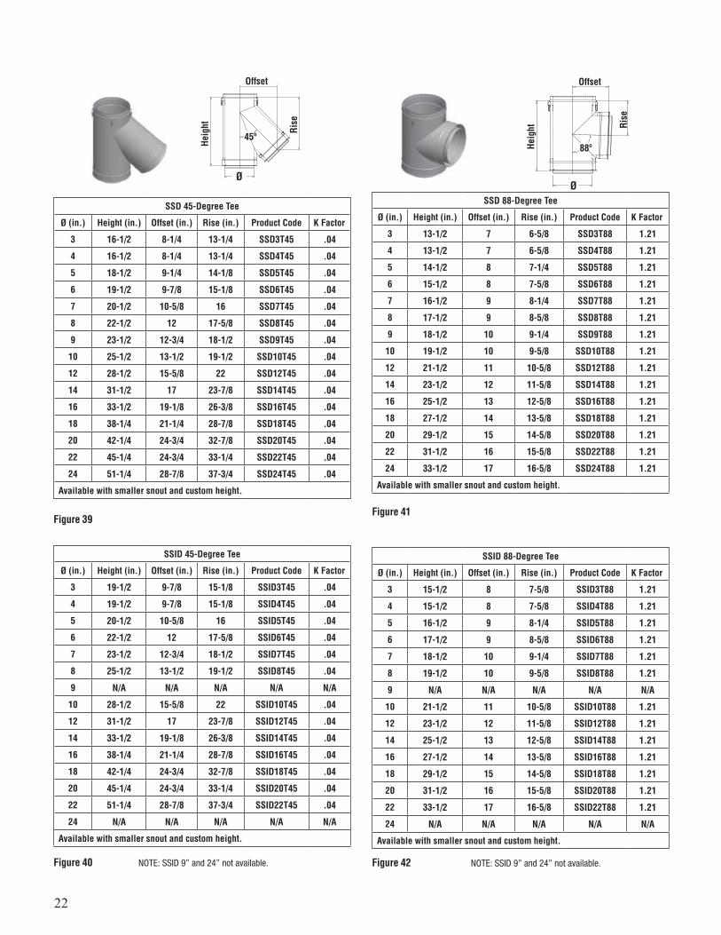
SSD 43-Degree Tee
Ø (in.) Height (in.) Offset (in.) Rise (in.) Product Code K Factor
3 16-1/2 8-1/4 13-3/8 SSD3T43 0.4
4 16-1/2 8-1/4 13-3/8 SSD4T43 0.4
5 18-1/2 8-7/8 14-3/8 SSD5T43 0.4
6 19-1/2 9-5/8 15-3/8 SSD6T43 0.4
7 20-1/2 10-1/4 16-1/4 SSD7T43 0.4
8 22-1/2 11-5/8 18 SSD8T43 0.4
9 23-1/2 12-1/4 18-7/8 SSD9T43 0.4
10 25-1/2 13 19-3/4 SSD10T43 0.4
12 28-1/2 15 22-3/8 SSD12T43 0.4
14 31-1/2 16-3/8 24-1/4 SSD14T43 0.4
16 33-1/2 18-1/2 26-1/4 SSD16T43 0.4
18 38-1/4 20-1/2 29-3/8 SSD18T43 0.4
20 42-1/4 23-7/8 33-1/2 SSD20T43 0.4
22 45-1/4 23-7/8 33-7/8 SSD22T43 0.4
24 51-1/4 27-7/8 38-1/2 SSD24T43 0.4
Available with smaller snout and custom height.
SSID 43-Degree Tee
Ø (in.) Height (in.) Offset (in.) Rise (in.) Product Code K Factor
3 19-1/2 9-5/8 15-3/8 SSID3T43 0.4
4 19-1/2 9-5/8 15-3/8 SSID4T43 0.4
5 20-1/2 10-1/4 16-1/4 SSID5T43 0.4
6 22-1/2 11-5/8 18 SSID6T43 0.4
7 23-1/2 12-1/4 18-7/8 SSID7T43 0.4
8 25-1/2 13 19-3/4 SSID8T43 0.4
9 N/A N/A N/A N/A N/A
10 28-1/2 15 22-3/8 SSID10T43 0.4
12 31-1/2 16-3/8 24-1/4 SSID12T43 0.4
14 33-1/2 18-1/2 26-1/4 SSID14T43 0.4
16 38-1/4 20-1/2 29-3/8 SSID16T43 0.4
18 42-1/4 23-7/8 33-1/2 SSID18T43 0.4
20 45-1/4 23-7/8 33-7/8 SSID20T43 0.4
22 51-1/4 27-7/8 38-1/2 SSID22T43 0.4
24 N/A N/A N/A N/A N/A
Available with smaller snout and custom height.
Figure 37
Figure 38
SSD & SSID VENTING TEESOffset
Rise
Heig
ht
Ø
43º
NOTE: SSID 9” and 24” not available.
NOTE: SSID 9” and 24” not available.
22
SSD 45-Degree Tee
Ø (in.) Height (in.) Offset (in.) Rise (in.) Product Code K Factor
3 16-1/2 8-1/4 13-1/4 SSD3T45 .04
4 16-1/2 8-1/4 13-1/4 SSD4T45 .04
5 18-1/2 9-1/4 14-1/8 SSD5T45 .04
6 19-1/2 9-7/8 15-1/8 SSD6T45 .04
7 20-1/2 10-5/8 16 SSD7T45 .04
8 22-1/2 12 17-5/8 SSD8T45 .04
9 23-1/2 12-3/4 18-1/2 SSD9T45 .04
10 25-1/2 13-1/2 19-1/2 SSD10T45 .04
12 28-1/2 15-5/8 22 SSD12T45 .04
14 31-1/2 17 23-7/8 SSD14T45 .04
16 33-1/2 19-1/8 26-3/8 SSD16T45 .04
18 38-1/4 21-1/4 28-7/8 SSD18T45 .04
20 42-1/4 24-3/4 32-7/8 SSD20T45 .04
22 45-1/4 24-3/4 33-1/4 SSD22T45 .04
24 51-1/4 28-7/8 37-3/4 SSD24T45 .04
Available with smaller snout and custom height.
SSID 45-Degree Tee
Ø (in.) Height (in.) Offset (in.) Rise (in.) Product Code K Factor
3 19-1/2 9-7/8 15-1/8 SSID3T45 .04
4 19-1/2 9-7/8 15-1/8 SSID4T45 .04
5 20-1/2 10-5/8 16 SSID5T45 .04
6 22-1/2 12 17-5/8 SSID6T45 .04
7 23-1/2 12-3/4 18-1/2 SSID7T45 .04
8 25-1/2 13-1/2 19-1/2 SSID8T45 .04
9 N/A N/A N/A N/A N/A
10 28-1/2 15-5/8 22 SSID10T45 .04
12 31-1/2 17 23-7/8 SSID12T45 .04
14 33-1/2 19-1/8 26-3/8 SSID14T45 .04
16 38-1/4 21-1/4 28-7/8 SSID16T45 .04
18 42-1/4 24-3/4 32-7/8 SSID18T45 .04
20 45-1/4 24-3/4 33-1/4 SSID20T45 .04
22 51-1/4 28-7/8 37-3/4 SSID22T45 .04
24 N/A N/A N/A N/A N/A
Available with smaller snout and custom height.
SSD 88-Degree Tee
Ø (in.) Height (in.) Offset (in.) Rise (in.) Product Code K Factor
3 13-1/2 7 6-5/8 SSD3T88 1.21
4 13-1/2 7 6-5/8 SSD4T88 1.21
5 14-1/2 8 7-1/4 SSD5T88 1.21
6 15-1/2 8 7-5/8 SSD6T88 1.21
7 16-1/2 9 8-1/4 SSD7T88 1.21
8 17-1/2 9 8-5/8 SSD8T88 1.21
9 18-1/2 10 9-1/4 SSD9T88 1.21
10 19-1/2 10 9-5/8 SSD10T88 1.21
12 21-1/2 11 10-5/8 SSD12T88 1.21
14 23-1/2 12 11-5/8 SSD14T88 1.21
16 25-1/2 13 12-5/8 SSD16T88 1.21
18 27-1/2 14 13-5/8 SSD18T88 1.21
20 29-1/2 15 14-5/8 SSD20T88 1.21
22 31-1/2 16 15-5/8 SSD22T88 1.21
24 33-1/2 17 16-5/8 SSD24T88 1.21
Available with smaller snout and custom height.
Figure 39
Figure 40
Figure 41
Offset Offset
Rise Ri
se
Heig
ht
Heig
ht
ØØ
45º88º
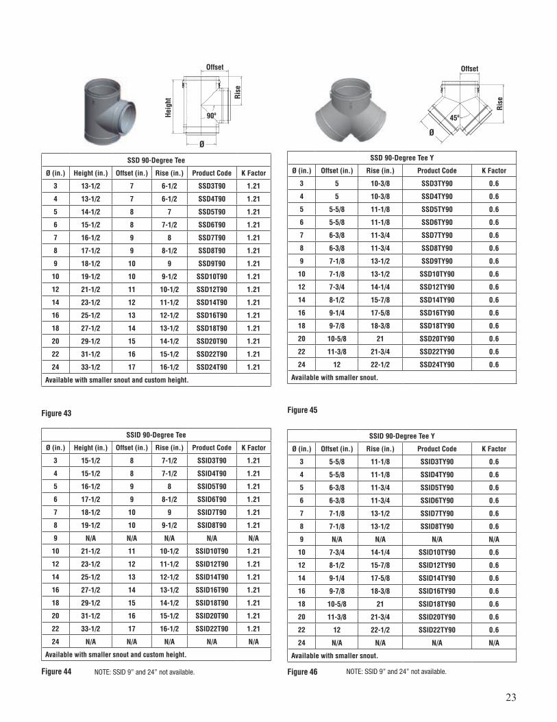
SSID 88-Degree Tee
Ø (in.) Height (in.) Offset (in.) Rise (in.) Product Code K Factor
3 15-1/2 8 7-5/8 SSID3T88 1.21
4 15-1/2 8 7-5/8 SSID4T88 1.21
5 16-1/2 9 8-1/4 SSID5T88 1.21
6 17-1/2 9 8-5/8 SSID6T88 1.21
7 18-1/2 10 9-1/4 SSID7T88 1.21
8 19-1/2 10 9-5/8 SSID8T88 1.21
9 N/A N/A N/A N/A N/A
10 21-1/2 11 10-5/8 SSID10T88 1.21
12 23-1/2 12 11-5/8 SSID12T88 1.21
14 25-1/2 13 12-5/8 SSID14T88 1.21
16 27-1/2 14 13-5/8 SSID16T88 1.21
18 29-1/2 15 14-5/8 SSID18T88 1.21
20 31-1/2 16 15-5/8 SSID20T88 1.21
22 33-1/2 17 16-5/8 SSID22T88 1.21
24 N/A N/A N/A N/A N/A
Available with smaller snout and custom height.
Figure 42NOTE: SSID 9” and 24” not available. NOTE: SSID 9” and 24” not available.
23
SSD 90-Degree Tee
Ø (in.) Height (in.) Offset (in.) Rise (in.) Product Code K Factor
3 13-1/2 7 6-1/2 SSD3T90 1.21
4 13-1/2 7 6-1/2 SSD4T90 1.21
5 14-1/2 8 7 SSD5T90 1.21
6 15-1/2 8 7-1/2 SSD6T90 1.21
7 16-1/2 9 8 SSD7T90 1.21
8 17-1/2 9 8-1/2 SSD8T90 1.21
9 18-1/2 10 9 SSD9T90 1.21
10 19-1/2 10 9-1/2 SSD10T90 1.21
12 21-1/2 11 10-1/2 SSD12T90 1.21
14 23-1/2 12 11-1/2 SSD14T90 1.21
16 25-1/2 13 12-1/2 SSD16T90 1.21
18 27-1/2 14 13-1/2 SSD18T90 1.21
20 29-1/2 15 14-1/2 SSD20T90 1.21
22 31-1/2 16 15-1/2 SSD22T90 1.21
24 33-1/2 17 16-1/2 SSD24T90 1.21
Available with smaller snout and custom height.
SSID 90-Degree Tee
Ø (in.) Height (in.) Offset (in.) Rise (in.) Product Code K Factor
3 15-1/2 8 7-1/2 SSID3T90 1.21
4 15-1/2 8 7-1/2 SSID4T90 1.21
5 16-1/2 9 8 SSID5T90 1.21
6 17-1/2 9 8-1/2 SSID6T90 1.21
7 18-1/2 10 9 SSID7T90 1.21
8 19-1/2 10 9-1/2 SSID8T90 1.21
9 N/A N/A N/A N/A N/A
10 21-1/2 11 10-1/2 SSID10T90 1.21
12 23-1/2 12 11-1/2 SSID12T90 1.21
14 25-1/2 13 12-1/2 SSID14T90 1.21
16 27-1/2 14 13-1/2 SSID16T90 1.21
18 29-1/2 15 14-1/2 SSID18T90 1.21
20 31-1/2 16 15-1/2 SSID20T90 1.21
22 33-1/2 17 16-1/2 SSID22T90 1.21
24 N/A N/A N/A N/A N/A
Available with smaller snout and custom height.
Figure 43
Figure 44
Offset
Rise
Heig
ht
Ø
90º
SSD 90-Degree Tee Y
Ø (in.) Offset (in.) Rise (in.) Product Code K Factor
3 5 10-3/8 SSD3TY90 0.6
4 5 10-3/8 SSD4TY90 0.6
5 5-5/8 11-1/8 SSD5TY90 0.6
6 5-5/8 11-1/8 SSD6TY90 0.6
7 6-3/8 11-3/4 SSD7TY90 0.6
8 6-3/8 11-3/4 SSD8TY90 0.6
9 7-1/8 13-1/2 SSD9TY90 0.6
10 7-1/8 13-1/2 SSD10TY90 0.6
12 7-3/4 14-1/4 SSD12TY90 0.6
14 8-1/2 15-7/8 SSD14TY90 0.6
16 9-1/4 17-5/8 SSD16TY90 0.6
18 9-7/8 18-3/8 SSD18TY90 0.6
20 10-5/8 21 SSD20TY90 0.6
22 11-3/8 21-3/4 SSD22TY90 0.6
24 12 22-1/2 SSD24TY90 0.6
Available with smaller snout.
SSID 90-Degree Tee Y
Ø (in.) Offset (in.) Rise (in.) Product Code K Factor
3 5-5/8 11-1/8 SSID3TY90 0.6
4 5-5/8 11-1/8 SSID4TY90 0.6
5 6-3/8 11-3/4 SSID5TY90 0.6
6 6-3/8 11-3/4 SSID6TY90 0.6
7 7-1/8 13-1/2 SSID7TY90 0.6
8 7-1/8 13-1/2 SSID8TY90 0.6
9 N/A N/A N/A N/A
10 7-3/4 14-1/4 SSID10TY90 0.6
12 8-1/2 15-7/8 SSID12TY90 0.6
14 9-1/4 17-5/8 SSID14TY90 0.6
16 9-7/8 18-3/8 SSID16TY90 0.6
18 10-5/8 21 SSID18TY90 0.6
20 11-3/8 21-3/4 SSID20TY90 0.6
22 12 22-1/2 SSID22TY90 0.6
24 N/A N/A N/A N/A
Available with smaller snout.
Figure 45
Figure 46
Offset
Rise
Ø
45º
NOTE: SSID 9” and 24” not available. NOTE: SSID 9” and 24” not available.
24
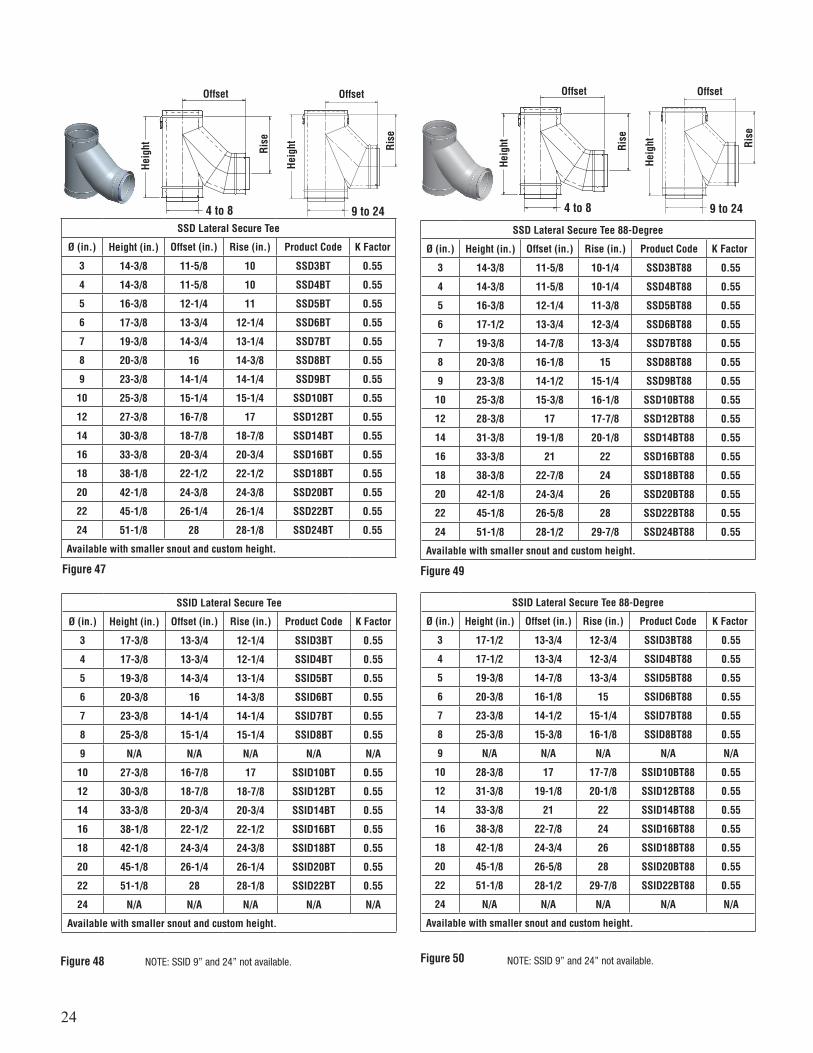
SSD Lateral Secure Tee
Ø (in.) Height (in.) Offset (in.) Rise (in.) Product Code K Factor
3 14-3/8 11-5/8 10 SSD3BT 0.55
4 14-3/8 11-5/8 10 SSD4BT 0.55
5 16-3/8 12-1/4 11 SSD5BT 0.55
6 17-3/8 13-3/4 12-1/4 SSD6BT 0.55
7 19-3/8 14-3/4 13-1/4 SSD7BT 0.55
8 20-3/8 16 14-3/8 SSD8BT 0.55
9 23-3/8 14-1/4 14-1/4 SSD9BT 0.55
10 25-3/8 15-1/4 15-1/4 SSD10BT 0.55
12 27-3/8 16-7/8 17 SSD12BT 0.55
14 30-3/8 18-7/8 18-7/8 SSD14BT 0.55
16 33-3/8 20-3/4 20-3/4 SSD16BT 0.55
18 38-1/8 22-1/2 22-1/2 SSD18BT 0.55
20 42-1/8 24-3/8 24-3/8 SSD20BT 0.55
22 45-1/8 26-1/4 26-1/4 SSD22BT 0.55
24 51-1/8 28 28-1/8 SSD24BT 0.55
Available with smaller snout and custom height.
SSID Lateral Secure Tee
Ø (in.) Height (in.) Offset (in.) Rise (in.) Product Code K Factor
3 17-3/8 13-3/4 12-1/4 SSID3BT 0.55
4 17-3/8 13-3/4 12-1/4 SSID4BT 0.55
5 19-3/8 14-3/4 13-1/4 SSID5BT 0.55
6 20-3/8 16 14-3/8 SSID6BT 0.55
7 23-3/8 14-1/4 14-1/4 SSID7BT 0.55
8 25-3/8 15-1/4 15-1/4 SSID8BT 0.55
9 N/A N/A N/A N/A N/A
10 27-3/8 16-7/8 17 SSID10BT 0.55
12 30-3/8 18-7/8 18-7/8 SSID12BT 0.55
14 33-3/8 20-3/4 20-3/4 SSID14BT 0.55
16 38-1/8 22-1/2 22-1/2 SSID16BT 0.55
18 42-1/8 24-3/4 24-3/8 SSID18BT 0.55
20 45-1/8 26-1/4 26-1/4 SSID20BT 0.55
22 51-1/8 28 28-1/8 SSID22BT 0.55
24 N/A N/A N/A N/A N/A
Available with smaller snout and custom height.
SSD Lateral Secure Tee 88-Degree
Ø (in.) Height (in.) Offset (in.) Rise (in.) Product Code K Factor
3 14-3/8 11-5/8 10-1/4 SSD3BT88 0.55
4 14-3/8 11-5/8 10-1/4 SSD4BT88 0.55
5 16-3/8 12-1/4 11-3/8 SSD5BT88 0.55
6 17-1/2 13-3/4 12-3/4 SSD6BT88 0.55
7 19-3/8 14-7/8 13-3/4 SSD7BT88 0.55
8 20-3/8 16-1/8 15 SSD8BT88 0.55
9 23-3/8 14-1/2 15-1/4 SSD9BT88 0.55
10 25-3/8 15-3/8 16-1/8 SSD10BT88 0.55
12 28-3/8 17 17-7/8 SSD12BT88 0.55
14 31-3/8 19-1/8 20-1/8 SSD14BT88 0.55
16 33-3/8 21 22 SSD16BT88 0.55
18 38-3/8 22-7/8 24 SSD18BT88 0.55
20 42-1/8 24-3/4 26 SSD20BT88 0.55
22 45-1/8 26-5/8 28 SSD22BT88 0.55
24 51-1/8 28-1/2 29-7/8 SSD24BT88 0.55
Available with smaller snout and custom height.
SSID Lateral Secure Tee 88-Degree
Ø (in.) Height (in.) Offset (in.) Rise (in.) Product Code K Factor
3 17-1/2 13-3/4 12-3/4 SSID3BT88 0.55
4 17-1/2 13-3/4 12-3/4 SSID4BT88 0.55
5 19-3/8 14-7/8 13-3/4 SSID5BT88 0.55
6 20-3/8 16-1/8 15 SSID6BT88 0.55
7 23-3/8 14-1/2 15-1/4 SSID7BT88 0.55
8 25-3/8 15-3/8 16-1/8 SSID8BT88 0.55
9 N/A N/A N/A N/A N/A
10 28-3/8 17 17-7/8 SSID10BT88 0.55
12 31-3/8 19-1/8 20-1/8 SSID12BT88 0.55
14 33-3/8 21 22 SSID14BT88 0.55
16 38-3/8 22-7/8 24 SSID16BT88 0.55
18 42-1/8 24-3/4 26 SSID18BT88 0.55
20 45-1/8 26-5/8 28 SSID20BT88 0.55
22 51-1/8 28-1/2 29-7/8 SSID22BT88 0.55
24 N/A N/A N/A N/A N/A
Available with smaller snout and custom height.
Figure 47
Figure 48
Figure 49
Figure 50
Offset Offset
Rise Rise
Heig
ht
Heig
ht
4 to 8 9 to 24
Offset Offset
Rise Rise
Heig
ht
Heig
ht
4 to 8 9 to 24
NOTE: SSID 9” and 24” not available. NOTE: SSID 9” and 24” not available.

25
SSD Barometric Tee
Ø (in.) Height (in.) Offset (in.) Rise (in.) Product Code K Factor
3 13-1/2 5 6-1/2 SSD3BMT 0.2
4 13-1/2 5 6-1/2 SSD4BMT 0.2
5 14-1/2 5 7 SSD5BMT 0.2
6 15-1/2 6 7-1/2 SSD6BMT 0.2
7 16-1/2 7 8 SSD7BMT 0.2
8 17-1/2 8 8-1/2 SSD8BMT 0.2
9 18-1/2 9 9 SSD9BMT 0.2
10 19-1/2 10 9-1/2 SSD10BMT 0.2
12 21-1/2 12 10-1/2 SSD12BMT 0.2
14 23-1/2 14 11-1/2 SSD14BMT 0.2
16 25-1/2 16 12-1/2 SSD16BMT 0.2
18 27-1/2 18 13-1/2 SSD18BMT 0.2
20 29-1/2 20 14-1/2 SSD20BMT 0.2
22 31-1/2 22 15-1/2 SSD22BMT 0.2
24 33-1/2 24 16-1/2 SSD24BMT 0.2
Available with smaller snout and custom height.
SSID Barometric Tee
Ø (in.) Height (in.) Offset (in.) Rise (in.) Product Code K Factor
3 15-1/2 6 7-1/2 SSID3BMT 0.2
4 15-1/2 6 7-1/2 SSID4BMT 0.2
5 16-1/2 7 8 SSID5BMT 0.2
6 17-1/2 8 8-1/2 SSID6BMT 0.2
7 18-1/2 9 9 SSID7BMT 0.2
8 19-1/2 10 9-1/2 SSID8BMT 0.2
9 N/A N/A N/A N/A N/A
10 21-1/2 12 10-1/2 SSID10BMT 0.2
12 23-1/2 14 11-1/2 SSID12BMT 0.2
14 25-1/2 16 12-1/2 SSID14BMT 0.2
16 27-1/2 18 13-1/2 SSID16BMT 0.2
18 29-1/2 20 14-1/2 SSID18BMT 0.2
20 31-1/2 22 15-1/2 SSID20BMT 0.2
22 33-1/2 24 16-1/2 SSID22BMT 0.2
24 N/A N/A N/A N/A N/A
Available with smaller snout and custom height.
Figure 51
Figure 52
Offset
Rise
Heig
ht
Ø
SSD & SSID Tee Cap
Ø (in.) Height (in.) Product Code SSD Product Code SSID
3 to 24 4-1/8 SSDØTC SSIDØTC
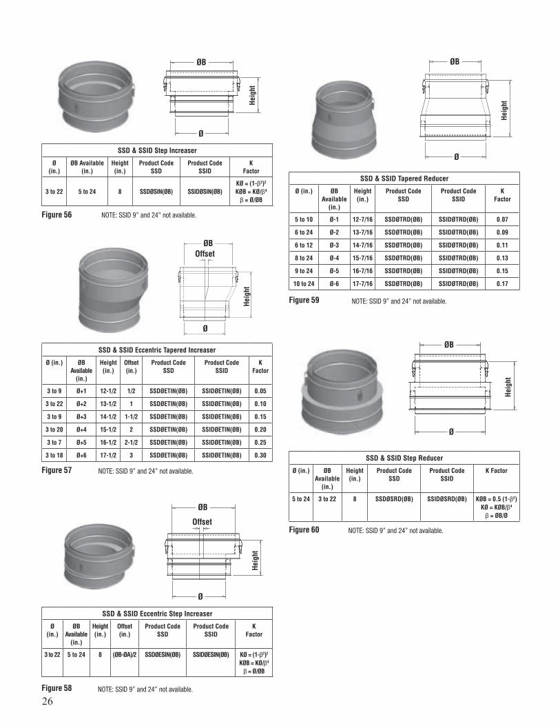
SSD & SSID Tapered Increaser
Ø (in.) ØB Available
(in.)
Height (in.)
Product CodeSSD
Product CodeSSID
KFactor
3 to 9 Ø+1 12-1/8 SSDØTIN(ØB) SSIDØTIN(ØB) 0.05
3 to 22 Ø+2 13-1/8 SSDØTIN(ØB) SSIDØTIN(ØB) 0.10
3 to 9 Ø+3 14-1/8 SSDØTIN(ØB) SSIDØTIN(ØB) 0.15
3 to 20 Ø+4 15-1/8 SSDØTIN(ØB) SSIDØTIN(ØB) 0.20
3 to 7 Ø+5 16-1/8 SSDØTIN(ØB) SSIDØTIN(ØB) 0.25
3 to 18 Ø+6 17-1/8 SSDØTIN(ØB) SSIDØTIN(ØB) 0.30
SSD & SSID Drain Tee Cap
Ø (in.) Height (in.) Product Code SSD Product Code SSID
3 to 24 4-1/8 SSDØDTC SSIDØDTC
Drain Ø4 – Ø10, 1/4 NPT, 1/2 0.DDrain Ø12 – Ø24, 3/8 NPT, 5/8 0.D
Figure 53
Figure 54
Figure 55
4-1/8
3-3/4
Drain NPT
Heig
ht
Ø
Ø
ØB
Ø
SSD & SSID VENTING ACCESSORIES
NOTE: SSID 9” and 24” not available.
NOTE: SSID 9” and 24” not available.
26
SSD & SSID Step Increaser
Ø(in.)
ØB Available(in.)
Height(in.)
Product CodeSSD
Product CodeSSID
KFactor
3 to 22 5 to 24 8 SSDØSIN(ØB) SSIDØSIN(ØB)KØ = (1-β2)2
KØB = KØ/β4
β = Ø/ØB
SSD & SSID Eccentric Tapered Increaser
Ø (in.) ØBAvailable
(in.)
Height(in.)
Offset(in.)
Product CodeSSD
Product CodeSSID
KFactor
3 to 9 Ø+1 12-1/2 1/2 SSDØETIN(ØB) SSIDØETIN(ØB) 0.05
3 to 22 Ø+2 13-1/2 1 SSDØETIN(ØB) SSIDØETIN(ØB) 0.10
3 to 9 Ø+3 14-1/2 1-1/2 SSDØETIN(ØB) SSIDØETIN(ØB) 0.15
3 to 20 Ø+4 15-1/2 2 SSDØETIN(ØB) SSIDØETIN(ØB) 0.20
3 to 7 Ø+5 16-1/2 2-1/2 SSDØETIN(ØB) SSIDØETIN(ØB) 0.25
3 to 18 Ø+6 17-1/2 3 SSDØETIN(ØB) SSIDØETIN(ØB) 0.30
SSD & SSID Eccentric Step Increaser
Ø(in.)
ØBAvailable
(in.)
Height(in.)
Offset(in.)
Product CodeSSD
Product CodeSSID
KFactor
3 to 22 5 to 24 8 (ØB-ØA)/2 SSDØESIN(ØB) SSIDØESIN(ØB) KØ = (1-β2)2
KØB = KØ/β4
β = Ø/ØB
Figure 56
Figure 57
Figure 58
Heig
htHe
ight
Heig
ht
ØB
ØB
ØB
Offset
Offset
Ø
Ø
Ø
SSD & SSID Tapered Reducer
Ø (in.) ØBAvailable
(in.)
Height(in.)
Product CodeSSD
Product CodeSSID
KFactor
5 to 10 Ø-1 12-7/16 SSDØTRD(ØB) SSIDØTRD(ØB) 0.07
6 to 24 Ø-2 13-7/16 SSDØTRD(ØB) SSIDØTRD(ØB) 0.09
6 to 12 Ø-3 14-7/16 SSDØTRD(ØB) SSIDØTRD(ØB) 0.11
8 to 24 Ø-4 15-7/16 SSDØTRD(ØB) SSIDØTRD(ØB) 0.13
9 to 24 Ø-5 16-7/16 SSDØTRD(ØB) SSIDØTRD(ØB) 0.15
10 to 24 Ø-6 17-7/16 SSDØTRD(ØB) SSIDØTRD(ØB) 0.17
SSD & SSID Step Reducer
Ø (in.) ØBAvailable
(in.)
Height(in.)
Product CodeSSD
Product CodeSSID
K Factor
5 to 24 3 to 22 8 SSDØSRD(ØB) SSIDØSRD(ØB) KØB = 0.5 (1-β2)KØ = KØB/β4
β = ØB/Ø
Figure 59
Figure 60
Heig
htHe
ight
ØB
ØB
Ø
Ø
NOTE: SSID 9” and 24” not available.
NOTE: SSID 9” and 24” not available.
NOTE: SSID 9” and 24” not available.
NOTE: SSID 9” and 24” not available.
NOTE: SSID 9” and 24” not available.
27
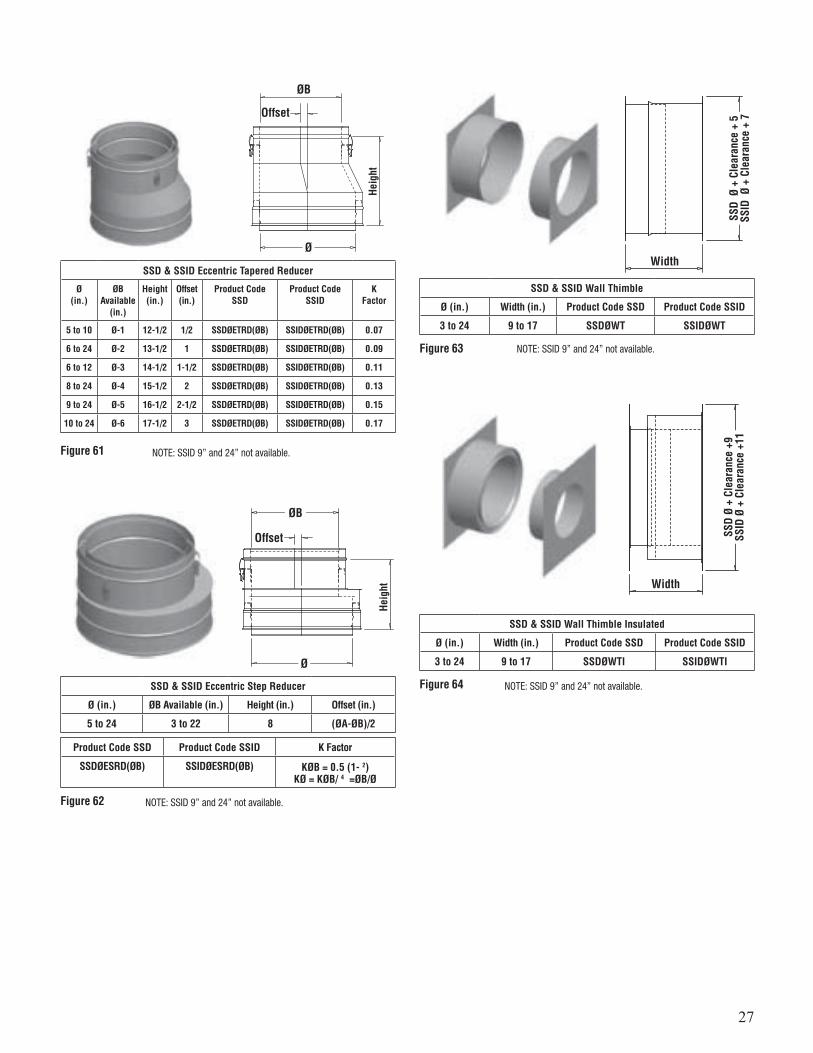
SSD & SSID Eccentric Tapered Reducer
Ø(in.)
ØBAvailable
(in.)
Height(in.)
Offset(in.)
Product CodeSSD
Product CodeSSID
KFactor
5 to 10 Ø-1 12-1/2 1/2 SSDØETRD(ØB) SSIDØETRD(ØB) 0.07
6 to 24 Ø-2 13-1/2 1 SSDØETRD(ØB) SSIDØETRD(ØB) 0.09
6 to 12 Ø-3 14-1/2 1-1/2 SSDØETRD(ØB) SSIDØETRD(ØB) 0.11
8 to 24 Ø-4 15-1/2 2 SSDØETRD(ØB) SSIDØETRD(ØB) 0.13
9 to 24 Ø-5 16-1/2 2-1/2 SSDØETRD(ØB) SSIDØETRD(ØB) 0.15
10 to 24 Ø-6 17-1/2 3 SSDØETRD(ØB) SSIDØETRD(ØB) 0.17
SSD & SSID Eccentric Step Reducer
Ø (in.) ØB Available (in.) Height (in.) Offset (in.)
5 to 24 3 to 22 8 (ØA-ØB)/2
Product Code SSD Product Code SSID K Factor
SSDØESRD(ØB) SSIDØESRD(ØB) KØB = 0.5 (1-2)KØ = KØB/4 =ØB/Ø
SSD & SSID Wall Thimble
Ø (in.) Width (in.) Product Code SSD Product Code SSID
3 to 24 9 to 17 SSDØWT SSIDØWT
SSD & SSID Wall Thimble Insulated
Ø (in.) Width (in.) Product Code SSD Product Code SSID
3 to 24 9 to 17 SSDØWTI SSIDØWTI
Figure 61
Figure 62
Figure 63
Figure 64
Heig
ht
SSD
Ø +
Cle
aran
ce +
5SS
ID Ø
+ C
lear
ance
+ 7
SSD
Ø +
Clea
ranc
e +9
SSID
Ø +
Cle
aran
ce +
11
Heig
ht
ØB
Offset
Width
Width
Offset
ØB
Ø
Ø
NOTE: SSID 9” and 24” not available.
NOTE: SSID 9” and 24” not available.
NOTE: SSID 9” and 24” not available.
NOTE: SSID 9” and 24” not available.
28
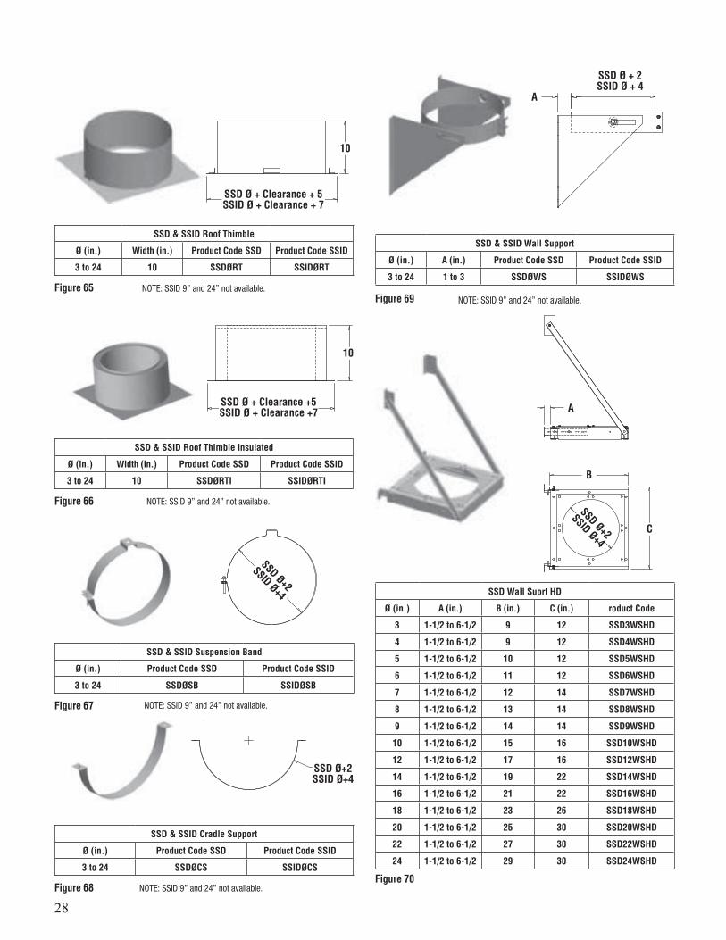
SSD & SSID Roof Thimble
Ø (in.) Width (in.) Product Code SSD Product Code SSID
3 to 24 10 SSDØRT SSIDØRT
SSD & SSID Wall Support
Ø (in.) A (in.) Product Code SSD Product Code SSID
3 to 24 1 to 3 SSDØWS SSIDØWS
SSD Wall Suort HD
Ø (in.) A (in.) B (in.) C (in.) roduct Code
3 1-1/2 to 6-1/2 9 12 SSD3WSHD
4 1-1/2 to 6-1/2 9 12 SSD4WSHD
5 1-1/2 to 6-1/2 10 12 SSD5WSHD
6 1-1/2 to 6-1/2 11 12 SSD6WSHD
7 1-1/2 to 6-1/2 12 14 SSD7WSHD
8 1-1/2 to 6-1/2 13 14 SSD8WSHD
9 1-1/2 to 6-1/2 14 14 SSD9WSHD
10 1-1/2 to 6-1/2 15 16 SSD10WSHD
12 1-1/2 to 6-1/2 17 16 SSD12WSHD
14 1-1/2 to 6-1/2 19 22 SSD14WSHD
16 1-1/2 to 6-1/2 21 22 SSD16WSHD
18 1-1/2 to 6-1/2 23 26 SSD18WSHD
20 1-1/2 to 6-1/2 25 30 SSD20WSHD
22 1-1/2 to 6-1/2 27 30 SSD22WSHD
24 1-1/2 to 6-1/2 29 30 SSD24WSHD
SSD & SSID Roof Thimble Insulated
Ø (in.) Width (in.) Product Code SSD Product Code SSID
3 to 24 10 SSDØRTI SSIDØRTI
SSD & SSID Suspension Band
Ø (in.) Product Code SSD Product Code SSID
3 to 24 SSDØSB SSIDØSB
SSD & SSID Cradle Support
Ø (in.) Product Code SSD Product Code SSID
3 to 24 SSDØCS SSIDØCS
Figure 65Figure 69
Figure 70
Figure 66
Figure 67
Figure 68
SSD Ø + Clearance + 5SSID Ø + Clearance + 7
SSD Ø + 2SSID Ø + 4
SSD Ø + Clearance +5SSID Ø + Clearance +7
SSD Ø+2
SSID Ø+4
SSD Ø+2
SSID Ø+4
SSD Ø+2SSID Ø+4
10
A
A
B
C
10
NOTE: SSID 9” and 24” not available.NOTE: SSID 9” and 24” not available.
NOTE: SSID 9” and 24” not available.
NOTE: SSID 9” and 24” not available.
NOTE: SSID 9” and 24” not available.
29
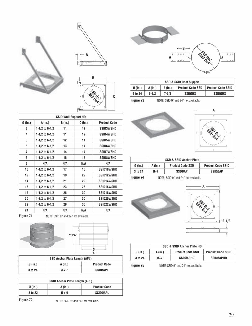
SSID Wall Support HD
Ø (in.) A (in.) B (in.) C (in.) Product Code
3 1-1/2 to 6-1/2 11 12 SSID3WSHD
4 1-1/2 to 6-1/2 11 12 SSID4WSHD
5 1-1/2 to 6-1/2 12 14 SSID5WSHD
6 1-1/2 to 6-1/2 13 14 SSID6WSHD
7 1-1/2 to 6-1/2 14 14 SSID7WSHD
8 1-1/2 to 6-1/2 15 16 SSID8WSHD
9 N/A N/A N/A N/A
10 1-1/2 to 6-1/2 17 16 SSID10WSHD
12 1-1/2 to 6-1/2 19 22 SSID12WSHD
14 1-1/2 to 6-1/2 21 22 SSID14WSHD
16 1-1/2 to 6-1/2 23 26 SSID16WSHD
18 1-1/2 to 6-1/2 25 30 SSID18WSHD
20 1-1/2 to 6-1/2 27 30 SSID20WSHD
22 1-1/2 to 6-1/2 29 30 SSID22WSHD
24 N/A N/A N/A N/A
Figure 71
SSD Ø+2
SSID Ø+4
A
B
C
NOTE: SSID 9” and 24” not available.
NOTE: SSID 9” and 24” not available.
NOTE: SSID 9” and 24” not available.
NOTE: SSID 9” and 24” not available.
SSD & SSID Roof Support
Ø (in.) A (in.) B (in.) Product Code SSD Product Code SSID
3 to 24 6-1/2 7-5/8 SSDØRS SSIDØRS
SSD & SSID Anchor Plate
Ø (in.) A (in.) Product Code SSD Product Code SSID
3 to 24 Ø+7 SSDØAP SSIDØAP
SSD & SSID Anchor Plate HD
Ø (in.) A (in.) Product Code SSD Product Code SSID
3 to 24 Ø+7 SSDØAPHD SSIDØAPHD
Figure 73
Figure 74
Figure 75
A
B
A
A
A
2-1/2
SSD Ø+2
SSID Ø+4
SSD Ø+2
SSID Ø+4
SSD Ø+2
SSID Ø+4
SSD Anchor Plate Length (APL)
Ø (in.) A (in.) Product Code
3 to 24 Ø + 7 SSDØAPL
SSID Anchor Plate Length (APL)
Ø (in.) A (in.) Product Code
3 to 22 Ø + 9 SSIDØAPL
Figure 72 NOTE: SSID 9” and 24” not available.
9-9/32
ØA
30
SSD & SSID Roof Brace
Ø (in.) Product Code SSD Product Code SSID
3 to 24 SSDØRB SSIDØRB
SSD & SSID Guy Wire Band
Ø (in.) Product Code SSD Product Code SSID
3 to 24 SSDØGWB SSIDØGWB
SSD & SSID Centering Band
Ø (in.) Product Code SSD Product Code SSID
3 to 24 SSDØCB SSIDØCB
SSD & SSID Guy Support
Ø (in.) Product Code SSD Product Code SSID
3 to 24 SSDØGS SSIDØGS
Figure 76
Figure 77
Figure 78
Figure 80
SSD Ø+2SSID Ø+4
6
SSD Ø+2SSID Ø+4
3/4
3
SSD & SSID Wall Guide
Ø (in.) A (in.) Product Code SSD Product Code SSID
3 to 24 1 to 4-1/2 SSDØWG SSIDØWG
SSD & SSID Double Male Adaptor
Ø(in.)
Effective Length(in.)
Product Code SSD
Product Code SSID
3 to 24 7-1/8 SSDØDMAU SSIDØDMAU
Figure 79
Figure 81
SSD Ø+2SSID Ø+4
EffectiveLength
A
Ø
NOTE: SSID 9” and 24” not available.
NOTE: SSID 9” and 24” not available.
NOTE: SSID 9” and 24” not available.
NOTE: SSID 9” and 24” not available.
NOTE: SSID 9” and 24” not available.
NOTE: SSID 9” and 24” not available.
Flexible strap by other
SSD Ø+2
SSID Ø+4
SSD Ø+2
SSID Ø+4
31
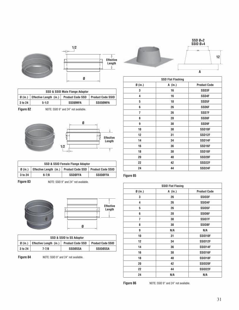
SSD & SSID Male Flange Adaptor
Ø (in.) Effective Length (in.) Product Code SSD Product Code SSID
3 to 24 5-1/2 SSDØMFA SSIDØMFA
SSD & SSID Female Flange Adaptor
Ø (in.) Effective Length (in.) Product Code SSD Product Code SSID
3 to 24 6-7/8 SSDØFFA SSIDØFFA
SSD & SSID to SS Adaptor
Ø (in.) Effective Length (in.) Product Code SSD Product Code SSID
3 to 24 7-7/8 SSDØSSA SSIDØSSA
SSD Flat Flashing
Ø (in.) A (in.) Product Code
3 16 SSD3F
4 16 SSD4F
5 18 SSD5F
6 26 SSD6F
7 26 SSD7F
8 28 SSD8F
9 30 SSD9F
10 30 SSD10F
12 31 SSD12F
14 34 SSD14F
16 36 SSD16F
18 38 SSD18F
20 40 SSD20F
22 42 SSD22F
24 44 SSD24F
Figure 82
Figure 83
Figure 84
Figure 85
EffectiveLength
EffectiveLength
EffectiveLength
Ø
Ø
Ø
SSD Ø+2SSID Ø+4
A
12
1/2
1/2
NOTE: SSID 9” and 24” not available.
NOTE: SSID 9” and 24” not available.
NOTE: SSID 9” and 24” not available.
SSID Flat Flasing
Ø (in.) A (in.) Product Code
3 26 SSID3F
4 26 SSID4F
5 26 SSID5F
6 28 SSID6F
7 30 SSID7F
8 30 SSID8F
9 N/A N/A
10 31 SSID10F
12 34 SSID12F
14 36 SSID14F
16 38 SSID16F
18 40 SSID18F
20 42 SSID20F
22 44 SSID22F
24 N/A N/A
Figure 86 NOTE: SSID 9” and 24” not available.

32
SSD Adjustable Flashing
Ø (in.) A (in.) Height (in.) Product Code
3 32 12-1/2 SSD3FA
4 32 12-1/2 SSD4FA
5 32 12-1/2 SSD5FA
6 34 12-1/2 SSD6FA
7 35-3/8 12-1/2 SSD7FA
8 36-1/2 12-1/2 SSD8FA
9 38 12-1/2 SSD9FA
10 38-1/2 12-1/2 SSD10FA
12 41 12-1/2 SSD12FA
14 43 12-1/2 SSD14FA
16 45 12-1/2 SSD16FA
18 47-1/4 12-1/2 SSD18FA
20 49-1/2 12-1/2 SSD20FA
22 51-1/2 12-1/2 SSD22FA
24 53-1/2 12-1/2 SSD24FA
SSID Adjustable Flashing
Ø (in.) A (in.) Height (in.) Product Code
3 34 12-1/2 SSID3FA
4 34 12-1/2 SSID4FA
5 35-3/8 12-1/2 SSID5FA
6 36-1/2 12-1/2 SSID6FA
7 38 12-1/2 SSID7FA
8 38-1/2 12-1/2 SSID8FA
9 N/A N/A N/A
10 41 12-1/2 SSID10FA
12 43 12-1/2 SSID12FA
14 45 12-1/2 SSID14FA
16 47-1/4 12-1/2 SSID16FA
18 49-1/2 12-1/2 SSID18FA
20 51-1/2 12-1/2 SSID20FA
22 53-1/2 12-1/2 SSID22FA
24 N/A N/A N/A
Figure 87
Figure 88
SSD Ø+2SSID Ø+4
A
12-1/2
SSD & SSID Storm Collar
Ø (in.) Product Code SSD Product Code SSID
3 to 24 SSDØSC SSIDØSC
Figure 89
Ø+2 SSDØ+4 SSID
7
SSD Rain Cap
Ø(in.)
Product CodeSSD
Product Code with Bird ScreenSSD
KFactor
3 to 24 SSDØRC SSDØRCB .50
SSID Rain Cap
Ø(in.)
Product CodeSSID
Product Code with Bird ScreenSSID
KFactor
3 to 24 SSIDØRC SSIDØRCB .50
Figure 90
SSD & SSID VENTING TERMINATIONS
NOTE: SSID 9” and 24” not available.
Adjustable from 5° to 30°.Roof pitch 1/12 to 7/12.
NOTE: SSID 9” and 24” not available.
NOTE: SSID 9” and 24” not available.
Ø
33
Ø
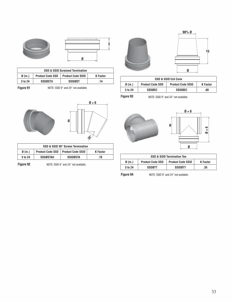
SSD & SSID Screened Termination
Ø (in.) Product Code SSD Product Code SSID K Factor
3 to 24 SSDØSTU SSIDØST .14
Figure 91
5
Ø + 6
Ø + 6
Ø +
6
90% Ø
ØØ
Ø
Ø
15
30°
SSD & SSID 30° Screen Termination
Ø (in.) Product Code SSD Product Code SSID K Factor
3 to 24 SSDØSTAU SSIDØSTA .70 SSD & SSID Termination Tee
Ø (in.) Product Code SSD Product Code SSID K Factor
3 to 24 SSDØTT SSIDØTT .35
SSD & SSID Exit Cone
Ø (in.) Product Code SSD Product Code SSID K Factor
3 to 24 SSDØEC SSIDØEC .60
Figure 92
Figure 94
Figure 93
NOTE: SSID 9” and 24” not available.
NOTE: SSID 9” and 24” not available.
NOTE: SSID 9” and 24” not available.
NOTE: SSID 9” and 24” not available.

34
Ø + 5
5
Effectivelength
Effectivelength
Ø
Ø
Ø
Ø
SSD & SSID Mitre Cut
Ø (in.) Product Code SSD Product Code SSID K Factor
3 to 24 SSDØMCU SSIDØMCU .14
SSD & SSID Closer Termination
Ø (in.) Product Code SSD Product Code SSID K Factor
3 to 24 SSDØCTU SSIDØCTU 0
SSD & SSID OEM Termination
Ø (in.) Product Code SSD Product Code SSID K Factor
3 to 24 SSDØOEMTAU SSIDØ0EMTAU 0
SS Lengths
Ø (in.) Effective Length (in.) Product Code
3 to 24 6-1/2 SSØL9
3 to 24 9-1/2 SSØL12
3 to 24 15-1/2 SSØL18
3 to 24 21-1/2 SSØL24
3 to 24 33-1/2 SSØL36
SS Adjustable Lengths
Ø (in.) Effective Length (in.) Product Code
3 to 24 4 to 5 SSØAL9
3 to 24 4 to 14 SSØAL18
Figure 95
Figure 96
Figure 97
Figure 98
Figure 99
SS VENTING LENGTHS
NOTE: SSID 9” and 24” not available.
NOTE: SSID 9” and 24” not available.
NOTE: SSID 9” and 24” not available.
Ø
20 24
Ø
EFFECTIVELENGTH
MAX
SS Telescopic Lengths
Ø (in.) Effective Length (in.) Product Code 32” Product Code 20”
3 to 24 14 to 20 SSØLAT32 SSØLAT20
3 to 24 20 to 32 SSØLAT32 SSØLAT20
Figure 99a

35
Effectivelength
Effectivelength
Ø
Ø
1
1
SS Test Port Lengths
Ø (in.) Effective Length (in.) Product Code
3 to 24 6-1/2 SSØTPL
Drain Ø4 – Ø24, 1/4 NPT, 1/2 0.D
SS Drain Length
Ø (in.) Effective Length (in.) Product Code K Factor
3 to 24 6-1/2 SSØDL 0.25
Drain Ø4 – Ø10, 1/4 NPT, 1/2 0.DDrain Ø12 – Ø24, 1/2 NPT, 5/8 0.D
Figure 100
Figure 101
Effectivelength
Ø
Plate for actuator
SS Damper Lengths
Ø (in.) Effective Length (in.) Product Code K Factor
3 to 24 15-1/2 SSØDAMP 0.60 to 9999
Figure 102
SS Damper Length Short Manual
Ø (in.) Effective Length (in.) Product Code K Factor
3 to 24 6-1/2 SSØDAMPS 0 to 9999
SS Damper Length Short
Ø (in.) Effective Length (in.) Product Code K Factor
3 to 24 7-1/8 SSØVFR 0 to 9999
SS Vent Flow Regulator Damper Blade
Ø (in.) Product Code
3 to 24 SSØVFN
For use on Cat. I and II boilers only
Figure 103
Figure 104
Figure 105
Cross Section View
Ø
Ø
6-1/2
7-1/2
1-11/16
3-3/8
Ø
7-1/23-3/8
Cross Section View
36
Rise2°
Ø
Offset
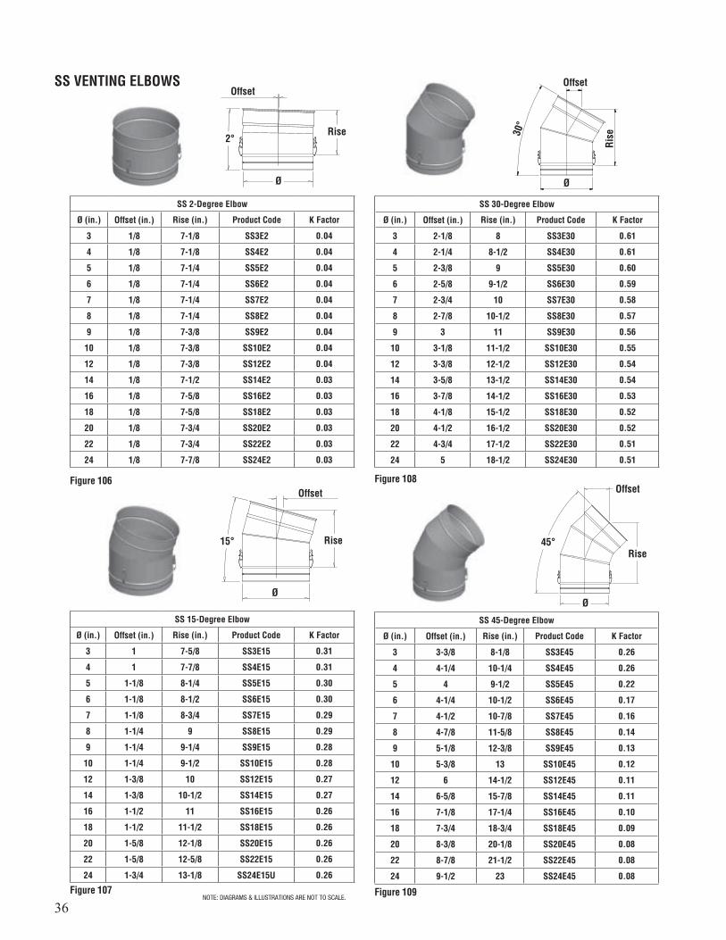
SS 2-Degree Elbow
Ø (in.) Offset (in.) Rise (in.) Product Code K Factor
3 1/8 7-1/8 SS3E2 0.04
4 1/8 7-1/8 SS4E2 0.04
5 1/8 7-1/4 SS5E2 0.04
6 1/8 7-1/4 SS6E2 0.04
7 1/8 7-1/4 SS7E2 0.04
8 1/8 7-1/4 SS8E2 0.04
9 1/8 7-3/8 SS9E2 0.04
10 1/8 7-3/8 SS10E2 0.04
12 1/8 7-3/8 SS12E2 0.04
14 1/8 7-1/2 SS14E2 0.03
16 1/8 7-5/8 SS16E2 0.03
18 1/8 7-5/8 SS18E2 0.03
20 1/8 7-3/4 SS20E2 0.03
22 1/8 7-3/4 SS22E2 0.03
24 1/8 7-7/8 SS24E2 0.03
Figure 106
SS VENTING ELBOWS
Rise
Rise
Rise15°
30°
45°
Ø
Ø
Ø
Offset
Offset
Offset
SS 15-Degree Elbow
Ø (in.) Offset (in.) Rise (in.) Product Code K Factor
3 1 7-5/8 SS3E15 0.31
4 1 7-7/8 SS4E15 0.31
5 1-1/8 8-1/4 SS5E15 0.30
6 1-1/8 8-1/2 SS6E15 0.30
7 1-1/8 8-3/4 SS7E15 0.29
8 1-1/4 9 SS8E15 0.29
9 1-1/4 9-1/4 SS9E15 0.28
10 1-1/4 9-1/2 SS10E15 0.28
12 1-3/8 10 SS12E15 0.27
14 1-3/8 10-1/2 SS14E15 0.27
16 1-1/2 11 SS16E15 0.26
18 1-1/2 11-1/2 SS18E15 0.26
20 1-5/8 12-1/8 SS20E15 0.26
22 1-5/8 12-5/8 SS22E15 0.26
24 1-3/4 13-1/8 SS24E15U 0.26
SS 30-Degree Elbow
Ø (in.) Offset (in.) Rise (in.) Product Code K Factor
3 2-1/8 8 SS3E30 0.61
4 2-1/4 8-1/2 SS4E30 0.61
5 2-3/8 9 SS5E30 0.60
6 2-5/8 9-1/2 SS6E30 0.59
7 2-3/4 10 SS7E30 0.58
8 2-7/8 10-1/2 SS8E30 0.57
9 3 11 SS9E30 0.56
10 3-1/8 11-1/2 SS10E30 0.55
12 3-3/8 12-1/2 SS12E30 0.54
14 3-5/8 13-1/2 SS14E30 0.54
16 3-7/8 14-1/2 SS16E30 0.53
18 4-1/8 15-1/2 SS18E30 0.52
20 4-1/2 16-1/2 SS20E30 0.52
22 4-3/4 17-1/2 SS22E30 0.51
24 5 18-1/2 SS24E30 0.51
SS 45-Degree Elbow
Ø (in.) Offset (in.) Rise (in.) Product Code K Factor
3 3-3/8 8-1/8 SS3E45 0.26
4 4-1/4 10-1/4 SS4E45 0.26
5 4 9-1/2 SS5E45 0.22
6 4-1/4 10-1/2 SS6E45 0.17
7 4-1/2 10-7/8 SS7E45 0.16
8 4-7/8 11-5/8 SS8E45 0.14
9 5-1/8 12-3/8 SS9E45 0.13
10 5-3/8 13 SS10E45 0.12
12 6 14-1/2 SS12E45 0.11
14 6-5/8 15-7/8 SS14E45 0.11
16 7-1/8 17-1/4 SS16E45 0.10
18 7-3/4 18-3/4 SS18E45 0.09
20 8-3/8 20-1/8 SS20E45 0.08
22 8-7/8 21-1/2 SS22E45 0.08
24 9-1/2 23 SS24E45 0.08
Figure 107
Figure 108
Figure 109NOTE: DIAGRAMS & ILLUSTRATIONS ARE NOT TO SCALE.
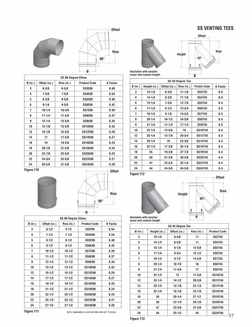
37
SS VENTING TEES
Rise
88°
Ø
Offset
Offset
Offset
Offset
Height
Height
SS 88-Degree Elbow
Ø (in.) Offset (in.) Rise (in.) Product Code K Factor
3 6-3/8 6-5/8 SS3E88 0.60
4 7-3/8 7-5/8 SS4E88 0.54
5 8-3/8 8-5/8 SS5E88 0.48
6 9-1/4 9-5/8 SS6E88 0.42
7 10-1/4 10-5/8 SS7E88 0.39
8 11-1/4 11-5/8 SS8E88 0.37
9 12-1/4 12-5/8 SS9E88 0.34
10 13-1/8 13-5/8 SS10E88 0.32
12 15-1/8 15-5/8 SS12E88 0.29
14 17 17-5/8 SS14E88 0.27
16 19 19-5/8 SS16E88 0.25
18 20-7/8 21-5/8 SS18E88 0.24
20 22-7/8 23-5/8 SS20E88 0.23
22 24-3/4 25-5/8 SS22E88 0.21
24 26-5/8 27-5/8 SS24E88 0.20
SS 90-Degree Elbow
Ø (in.) Offset (in.) Rise (in.) Product Code K Factor
3 6-1/2 6-1/2 SS3E90 0.54
4 7-1/2 7-1/2 SS4E90 0.54
5 8-1/2 8-1/2 SS5E90 0.48
6 9-1/2 9-1/2 SS6E90 0.42
7 10-1/2 10-1/2 SS7E90 0.39
8 11-1/2 11-1/2 SS8E90 0.37
9 12-1/2 12-1/2 SS9E90 0.34
10 13-1/2 13-1/2 SS10E90 0.32
12 15-1/2 15-1/2 SS12E90 0.29
14 17-1/2 17-1/2 SS14E90 0.27
16 19-1/2 19-1/2 SS16E90 0.25
18 21-1/2 21-1/2 SS18E90 0.24
20 23-1/2 23-1/2 SS20E90 0.23
22 25-1/2 25-1/2 SS22E90 0.21
24 27-1/2 27-1/2 SS24E90 0.20
Figure 110
Figure 111
Figure 112
Figure 113
90°
43°
45°Rise
Rise
Rise
Ø
Ø
Ø
SS 43-Degree Tee
Ø (in.) Height (in.) Offset (in.) Rise (in.) Prodct Code K Factor
3 14-1/4 6-3/8 11-1/8 SS3T43 0.4
4 14-1/4 6-3/8 11-1/8 SS4T43 0.4
5 15-1/4 7-3/4 12-7/8 SS5T43 0.4
6 17-1/4 8-1/2 13-3/4 SS6T43 0.4
7 18-1/4 9-1/8 14-3/4 SS7T43 0.4
8 20-1/4 10-1/2 16-3/8 SS8T43 0.4
9 21-1/4 11-1/4 17-1/4 SS9T43 0.4
10 22-1/4 12-5/8 19 SS10T43 0.4
12 25-1/4 13-7/8 20-3/4 SS12T43 0.4
14 29-1/4 16 23-3/8 SS14T43 0.4
16 32-1/4 17-3/8 25-1/4 SS16T43 0.4
18 35 19-3/8 27-7/8 SS18T43 0.4
20 38 21-3/8 30-3/8 SS20T43 0.4
22 41 22-3/4 32-1/4 SS22T43 0.4
24 44 24-5/8 34-5/8 SS24T43 0.4
SS 45-Degree Tee
Ø (in.) Height (in.) Offset (in.) Rise (in.) Product Code
3 14-1/4 6-5/8 11 SS3T45
4 14-1/4 6-5/8 11 SS4T45
5 15-1/4 8-1/8 12-5/8 SS5T45
6 17-1/4 8-3/4 13-1/2 SS6T45
7 18-1/4 9-1/2 14-3/8 SS7T45
8 20-1/4 10-7/8 16 SS8T45
9 21-1/4 11-5/8 17 SS9T45
10 22-1/4 13 17-5/8 SS10T45
12 25-1/4 14-1/2 20-3/8 SS12T45
14 29-1/4 15-7/8 22-1/4 SS14T45
16 32-1/4 18-1/8 24-7/8 SS16T45
18 35 20-1/4 27-1/2 SS18T45
20 38 22-1/4 29-7/8 SS20T45
22 41 23-5/8 31-5/8 SS22T45
24 44 25-1/2 34 SS24T45
Available with smaller snout and custom height.
Available with smaller snout and custom height.
NOTE: DIAGRAMS & ILLUSTRATIONS ARE NOT TO SCALE.
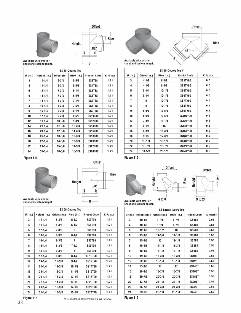
38
Offset
Height
Figure 114 Figure 116
Figure 117Figure 115
88°
Rise
Ø
SS 88-Degree Tee
Ø (in.) Height (in.) Offset (in.) Rise (in.) Product Code K Factor
3 11-1/4 6-3/8 5-5/8 SS3T88 1.21
4 11-1/4 6-3/8 5-5/8 SS4T88 1.21
5 12-1/4 7-3/8 6-1/4 SS5T88 1.21
6 13-1/4 7-3/8 6-5/8 SS6T88 1.21
7 14-1/4 8-3/8 7-1/4 SS7T88 1.21
8 15-1/4 8-3/8 7-5/8 SS8T88 1.21
9 16-1/4 9-3/8 8-1/4 SS9T88 1.21
10 17-1/4 9-3/8 8-5/8 SS10T88 1.21
12 19-1/4 10-3/8 9-3/4 SS12T88 1.21
14 21-1/4 11-3/8 10-3/4 SS14T88 1.21
16 23-1/4 12-3/8 11-3/4 SS16T88 1.21
18 25-1/4 13-3/8 12-3/4 SS18T88 1.21
20 27-1/4 14-3/8 13-3/4 SS20T88 1.21
22 29-1/4 15-3/8 14-3/4 SS22T88 1.21
24 31-1/4 16-3/8 15-3/4 SS24T88 1.21
Available with smaller snout and custom height.
Available with smaller snout and custom height.
Available with smaller snout and custom height.
Offset
Offset
Height90°
45°
Rise
Rise
Ø
Ø
SS 90-Degree Tee
Ø (in.) Height (in.) Offset (in.) Rise (in.) Prodct Code K Factor
3 11-1/4 6-3/8 5-1/2 SS3T90 1.21
4 11-1/4 6-3/8 5-1/2 SS4T90 1.21
5 12-1/4 7-3/8 6 SS5T90 1.21
6 13-1/4 7-3/8 6-1/2 SS6T90 1.21
7 14-1/4 8-3/8 7 SS7T90 1.21
8 15-1/4 8-3/8 7-1/2 SS8T90 1.21
9 16-1/4 9-3/8 8 SS9T90 1.21
10 17-1/4 9-3/8 8-1/2 SS10T90 1.21
12 19-1/4 10-3/8 9-1/2 SS12T90 1.21
14 21-1/4 11-3/8 10-1/2 SS14T90 1.21
16 23-1/4 12-3/8 11-1/2 SS16T90 1.21
18 25-1/4 13-3/8 12-1/2 SS18T90 1.21
20 27-1/4 14-3/8 13-1/2 SS20T90 1.21
22 29-1/4 15-3/8 14-1/2 SS22T90 1.21
24 31-1/4 16-3/8 15-1/2 SS24T90 1.21
SS 90-Degree Tee Y
Ø (in.) Offset (in.) Rise (in.) Prodct Code K Factor
3 4-1/2 8-1/2 SS3TY90 0.6
4 4-1/2 8-1/2 SS4TY90 0.6
5 5-1/4 10-1/8 SS5TY90 0.6
6 5-1/4 10-1/8 SS6TY90 0.6
7 6 10-7/8 SS7TY90 0.6
8 6 10-7/8 SS8TY90 0.6
9 6-5/8 12-5/8 SS9TY90 0.6
10 6-5/8 12-5/8 SS10TY90 0.6
12 7-3/8 13-1/4 SS12TY90 0.6
14 8-1/8 15 SS14TY90 0.6
16 8-3/4 16-3/4 SS16TY90 0.6
18 9-1/2 17-3/8 SS18TY90 0.6
20 10-1/4 18-1/8 SS20TY90 0.6
22 10-7/8 18-7/8 SS22TY90 0.6
24 11-5/8 20-1/2 SS24TY90 0.6
Available with smaller snout and custom height.
SS Lateral Secre Tee
Ø (in.) Height (in.) Offset (in.) Rise (in.) Prodct Code K Factor
3 10-1/8 9-1/4 8-7/8 SS3BT 0.55
4 10-1/8 9-1/4 8-7/8 SS4BT 0.55
5 12-1/8 10-1/2 10 SS5BT 0.55
6 13-1/8 11-3/4 11-1/8 SS6BT 0.55
7 15-1/8 13 12-1/4 SS7BT 0.55
8 16-1/8 14-1/4 13-3/8 SS8BT 0.55
9 18-1/8 12-1/2 12-1/2 SS9BT 0.55
10 19-1/8 13-3/8 13-3/8 SS10BT 0.55
12 22-1/8 15-1/4 15-1/4 SS12BT 0.55
14 25-1/8 17 17 SS14BT 0.55
16 28-1/8 18-7/8 18-7/8 SS16BT 0.55
18 30-7/8 20-3/4 20-3/4 SS18BT 0.55
20 33-7/8 22-1/2 22-1/2 SS20BT 0.55
22 36-7/8 24-3/8 24-3/8 SS22BT 0.55
24 39-7/8 26-1/8 26-1/4 SS24BT 0.55
Offset
4 to 8 9 to 24
Offset
Heig
ht
Heig
ht
Rise
Rise
NOTE: DIAGRAMS & ILLUSTRATIONS ARE NOT TO SCALE.

39
SS VENTING ACCESSORIES
Figure 118
Figure 119
Figure 120
Height
Available with smaller snout and custom height.
Offset
Rise
Ø
SS Lateral Secre Tee 88-Degree
Ø (in.) Height (in.) Offset (in.) Rise (in.) Prodct Code K Factor
3 11-1/8 9-1/4 9-1/4 SS3BT88 0.55
4 11-1/8 9-1/4 9-1/4 SS4BT88 0.55
5 12-1/8 10-1/2 10-1/2 SS5BT88 0.55
6 14-1/8 11-3/4 11-3/4 SS6BT88 0.55
7 16-1/8 13 13 SS7BT88 0.55
8 17-1/8 14-1/4 14-1/8 SS8BT88 0.55
9 19-1/8 12-5/8 13-1/4 SS9BT88 0.55
10 20-1/8 13-1/2 14-1/4 SS10BT88 0.55
12 23-1/8 15-3/8 16-1/8 SS12BT88 0.55
14 26-1/8 17-3/8 18-1/8 SS14BT88 0.55
16 29-1/8 19-1/8 20-1/8 SS16BT88 0.55
18 31-7/8 21 22 SS18BT88 0.55
20 34-7/8 22-7/8 24 SS20BT88 0.55
22 37-7/8 24-3/4 26 SS22BT88 0.55
24 40-7/8 26-5/8 28 SS24BT88 0.55
SS Barometric Tee
Ø (in.) Height (in.) Offset (in.) Rise (in.) Product Code K Factor
3 11-1/4 5 5-1/2 SS3BMT 0.2
4 11-1/4 5 5-1/2 SS4BMT 0.2
5 12-1/4 5 6 SS5BMT 0.2
6 13-1/4 6 6-1/2 SS6BMT 0.2
7 14-1/4 7 7 SS7BMT 0.2
8 15-1/4 8 7-1/2 SS8BMT 0.2
9 16-1/4 9 8 SS9BMT 0.2
10 17-1/4 10 8-1/2 SS10BMT 0.2
12 19-1/4 12 9-1/2 SS12BMT 0.2
14 21-1/4 14 10-1/2 SS14BMT 0.2
16 23-1/4 16 11-1/2 SS16BMT 0.2
18 25-1/4 18 12-1/2 SS18BMT 0.2
20 27-1/4 20 13-1/2 SS20BMT 0.2
22 29-1/4 22 14-1/2 SS22BMT 0.2
24 31-1/4 24 15-1/2 SS24BMT 0.2
SS Tee Cap
Ø (in.) Height (in.) Product Code
3 to 24 3-1/2 SSØTC
Figure 121
Figure 122
SS Drain Tee Cap
Ø (in.) Height (in.) Product Code
3 to 24 3-1/2 SSØDTC
Drain Ø4 – Ø10, 1/4 NPT, 1/2 0.DDrain Ø12 – Ø24, 3/8 NPT, 5/8 0.D
3-1/2
Drain NPT
Ø
SS Tapered Increaser
Ø (in.) ØB Available (in.) Height (in.) Product Code K Factor
3 to 9 Ø+1 11-7/8 SSØTIN(ØB) 0.05
3 to 22 Ø+2 12-7/8 SSØTIN(ØB) 0.10
3 to 9 Ø+3 13-7/8 SSØTIN(ØB) 0.15
3 to 20 Ø+4 14-7/8 SSØTIN(ØB) 0.20
3 to 7 Ø+5 15-7/8 SSØTIN(ØB) 0.25
3 to 18 Ø+6 16-7/8 SSØTIN(ØB) 0.30
Ø
Ø B
Height
Available with smaller snout and custom height.
Offset
4 to 8 9 to 24
Offset
Heig
ht
Heig
ht
Rise
Rise
3-1/2Ø
Drain NPT
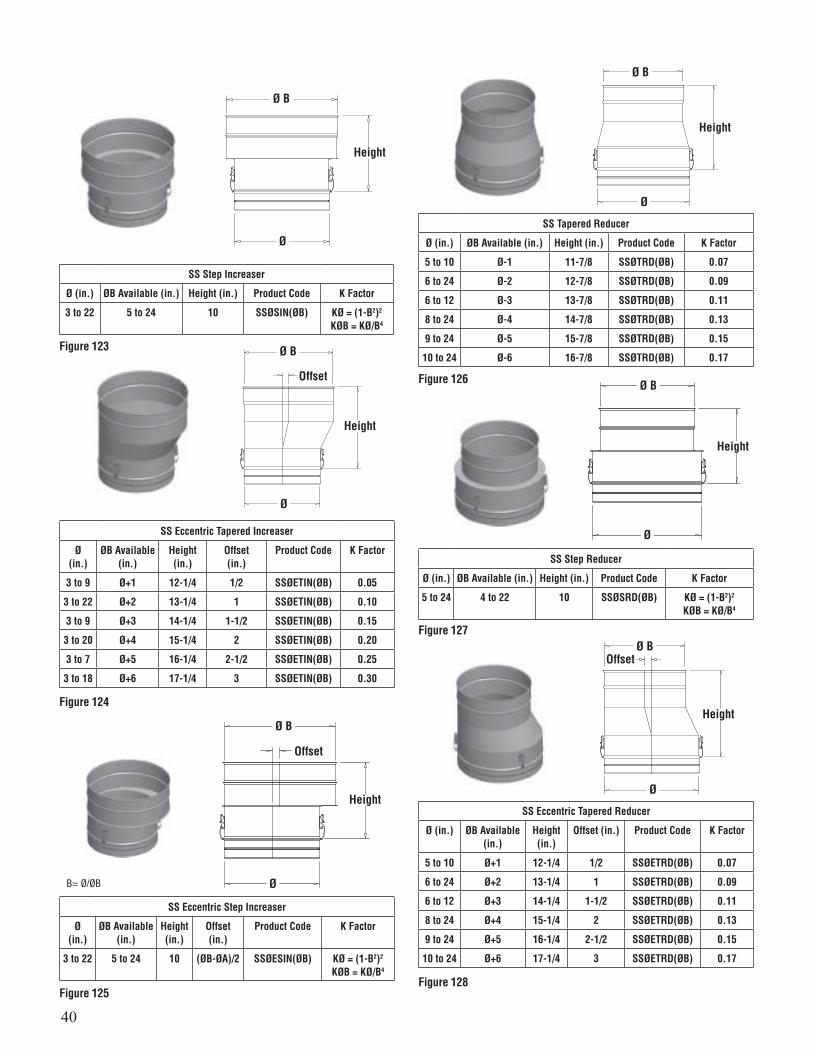
40
Figure 123
SS Step Increaser
Ø (in.) ØB Available (in.) Height (in.) Product Code K Factor
3 to 22 5 to 24 10 SSØSIN(ØB) KØ = (1-B2)2
KØB = KØ/B4
Ø
Ø B
Height
Figure 124
SS Eccentric Tapered Increaser
Ø(in.)
ØB Available(in.)
Height(in.)
Offset(in.)
Product Code K Factor
3 to 9 Ø+1 12-1/4 1/2 SSØETIN(ØB) 0.05
3 to 22 Ø+2 13-1/4 1 SSØETIN(ØB) 0.10
3 to 9 Ø+3 14-1/4 1-1/2 SSØETIN(ØB) 0.15
3 to 20 Ø+4 15-1/4 2 SSØETIN(ØB) 0.20
3 to 7 Ø+5 16-1/4 2-1/2 SSØETIN(ØB) 0.25
3 to 18 Ø+6 17-1/4 3 SSØETIN(ØB) 0.30
Ø
Ø B
Height
Offset
SS Eccentric Step Increaser
Ø (in.)
ØB Available(in.)
Height (in.)
Offset (in.)
Product Code K Factor
3 to 22 5 to 24 10 (ØB-ØA)/2 SSØESIN(ØB) KØ = (1-B2)2
KØB = KØ/B4
Ø
Ø B
Height
Offset
Figure 125
Figure 126
Figure 127
Figure 128
SS Tapered Reducer
Ø (in.) ØB Available (in.) Height (in.) Product Code K Factor
5 to 10 Ø-1 11-7/8 SSØTRD(ØB) 0.07
6 to 24 Ø-2 12-7/8 SSØTRD(ØB) 0.09
6 to 12 Ø-3 13-7/8 SSØTRD(ØB) 0.11
8 to 24 Ø-4 14-7/8 SSØTRD(ØB) 0.13
9 to 24 Ø-5 15-7/8 SSØTRD(ØB) 0.15
10 to 24 Ø-6 16-7/8 SSØTRD(ØB) 0.17
Height
Ø
Ø B
SS Step Reducer
Ø (in.) ØB Available (in.) Height (in.) Product Code K Factor
5 to 24 4 to 22 10 SSØSRD(ØB) KØ = (1-B2)2
KØB = KØ/B4
Height
Ø
Ø B
Ø
Ø B
Height
Offset
SS Eccentric Tapered Reducer
Ø (in.) ØB Available (in.)
Height(in.)
Offset (in.) Product Code K Factor
5 to 10 Ø+1 12-1/4 1/2 SSØETRD(ØB) 0.07
6 to 24 Ø+2 13-1/4 1 SSØETRD(ØB) 0.09
6 to 12 Ø+3 14-1/4 1-1/2 SSØETRD(ØB) 0.11
8 to 24 Ø+4 15-1/4 2 SSØETRD(ØB) 0.13
9 to 24 Ø+5 16-1/4 2-1/2 SSØETRD(ØB) 0.15
10 to 24 Ø+6 17-1/4 3 SSØETRD(ØB) 0.17
B= Ø/ØB
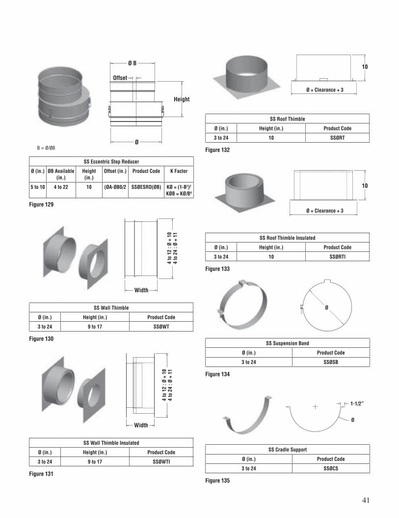
41
Figure 129
Ø
Ø B
Height
Offset
SS Eccentric Step Reducer
Ø (in.) ØB Available(in.)
Height (in.)
Offset (in.) Product Code K Factor
5 to 10 4 to 22 10 (ØA-ØB0/2 SSØESRD(ØB) KØ = (1-B2)2
KØB = KØ/B4
Figure 130
Figure 131
Width
Width
4 to
12
: Ø +
10
4 to
24
: Ø +
11
SS Wall Thimble
Ø (in.) Height (in.) Product Code
3 to 24 9 to 17 SSØWT
SS Wall Thimble Insulated
Ø (in.) Height (in.) Product Code
3 to 24 9 to 17 SSØWTI
Figure 132
10
Ø + Clearance + 3
SS Roof Thimble
Ø (in.) Height (in.) Product Code
3 to 24 10 SSØRT
Figure 133
Figure 134
Figure 135
10
Ø + Clearance + 3
Ø
Ø
1-1/2”
SS Roof Thimble Insulated
Ø (in.) Height (in.) Product Code
3 to 24 10 SSØRTI
SS Suspension Band
Ø (in.) Product Code
3 to 24 SSØSB
SS Cradle Support
Ø (in.) Product Code
3 to 24 SSØCS
B = Ø/ØB
4 to
12
: Ø +
10
4 to
24
: Ø +
11
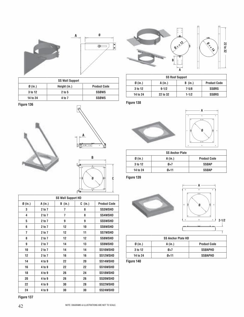
42
SS Wall Support HD
Ø (in.) A (in.) B (in.) C (in.) Product Code
3 2 to 7 7 8 SS3WSHD
4 2 to 7 7 8 SS4WSHD
5 2 to 7 9 9 SS5WSHD
6 2 to 7 12 10 SS6WSHD
7 2 to 7 12 11 SS7WSHD
8 2 to 7 12 12 SS8WSHD
9 2 to 7 14 13 SS9WSHD
10 2 to 7 14 14 SS10WSHD
12 2 to 7 16 16 SS12WSHD
14 4 to 9 22 20 SS14WSHD
16 4 to 9 22 22 SS16WSHD
18 4 to 9 26 24 SS18WSHD
20 4 to 9 26 26 SS20WSHD
22 4 to 9 30 28 SS22WSHD
24 4 to 9 30 30 SS24WSHD
SS Roof Support
Ø (in.) A (in.) B (in.) Product Code
3 to 12 6-1/2 7-5/8 SSØRS
14 to 24 22 to 32 1-1/2 SSØRS
SS Anchor Plate
Ø (in.) A (in.) Product Code
3 to 12 Ø+7 SSØAP
14 to 24 Ø+11 SSØAP
SS Anchor Plate HD
Ø (in.) A (in.) Product Code
3 to 12 Ø+7 SSØAPHD
14 to 24 Ø+11 SSØAPHD
Figure 136
Figure 137
Figure 138
Figure 139
Figure 140
A
B
A
Ø
A
A
A
B
22 to 32Ø > = 12 Ø < = 14
Ø C
SS Wall Support
Ø (in.) Height (in.) Product Code
3 to 12 2 to 5 SSØWS
14 to 24 4 to 7 SSØWS
Ø
Ø
2-1/2
NOTE: DIAGRAMS & ILLUSTRATIONS ARE NOT TO SCALE.

43
SS Roof Brace
Ø (in.) Product Code
3 to 24 SSØRB
SS Guy Wire Band
Ø (in.) Product Code
3 to 24 SSØGWB
SS Centering Band
Ø (in.) Product Code
3 to 24 SSØCB
Figure 142
Figure 143
Figure 144
3
ØØ
Ø
6
SS Wall Guide
Ø (in.) A (in.) Product Code
3 to 24 2 to 5-1/2 SSØWG
14 to 24 4 to 7-1/2 SSØWG
SS Guy Support
Ø (in.) Product Code
3 to 24 SSØGS
SS Double Male Adaptor
Ø (in.) Effective Length (in.) Product Code
3 to 24 3-7/8 SSØDMA
SS Male Flange Adaptor
Ø (in.) Effective Length (in.) Product Code
3 to 24 4-7/8 SSØMFA
Figure 145
Figure 146
Figure 147
Figure 148
Ø
Ø
1/2
Effectivelength
Effectivelength
Ø
A
3/4
3
Ø
SS Anchor Plate Length (APL)
Ø (in.) A (in.) Product Code
3 to 12 Ø + 7 SSØAPL
14 to 24 Ø + 11 SSØAPL
Figure 141
9-9/32
Ø
A
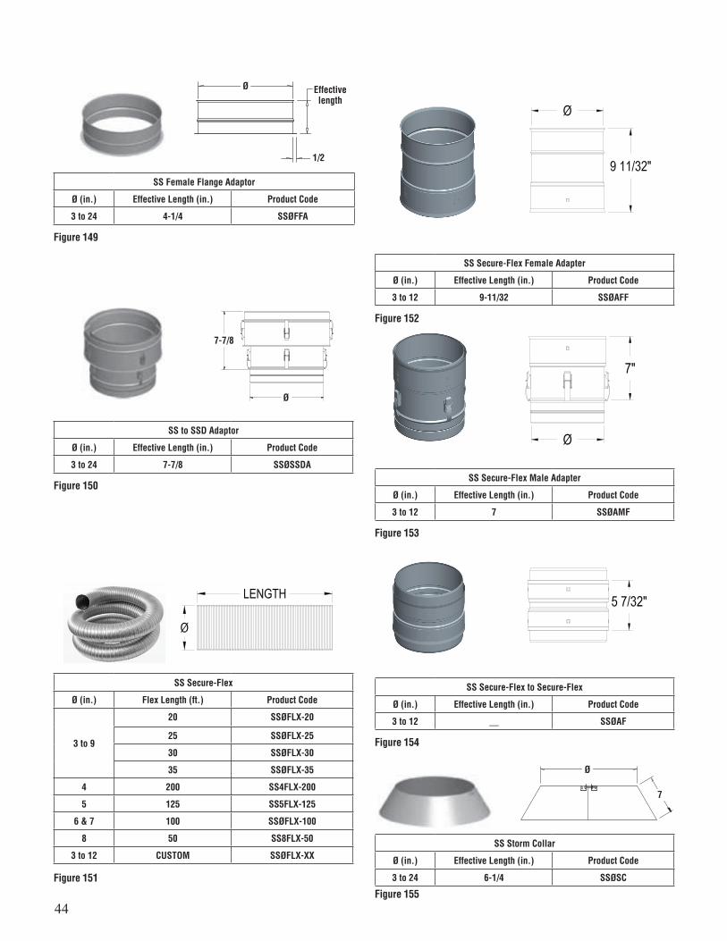
44
SS Female Flange Adaptor
Ø (in.) Effective Length (in.) Product Code
3 to 24 4-1/4 SSØFFA
SS to SSD Adaptor
Ø (in.) Effective Length (in.) Product Code
3 to 24 7-7/8 SSØSSDA
Figure 149
Figure 150
Ø
1/2
Effectivelength
Ø
7-7/8
SS Storm Collar
Ø (in.) Effective Length (in.) Product Code
3 to 24 6-1/4 SSØSC
Figure 155
Ø
7
SS Secure-Flex
Ø (in.) Flex Length (ft.) Product Code
3 to 9
20 SSØFLX-20
25 SSØFLX-25
30 SSØFLX-30
35 SSØFLX-35
4 200 SS4FLX-200
5 125 SS5FLX-125
6 & 7 100 SSØFLX-100
8 50 SS8FLX-50
3 to 12 CUSTOM SSØFLX-XX
Figure 151
SS Secure-Flex Female Adapter
Ø (in.) Effective Length (in.) Product Code
3 to 12 9-11/32 SSØAFF
Figure 152
SS Secure-Flex Male Adapter
Ø (in.) Effective Length (in.) Product Code
3 to 12 7 SSØAMF
Figure 153
SS Secure-Flex to Secure-Flex
Ø (in.) Effective Length (in.) Product Code
3 to 12 __ SSØAF
Figure 154
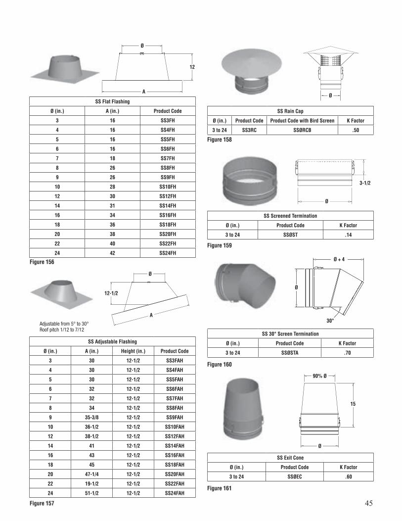
45
Figure 156
Figure 157
SS Flat Flashing
Ø (in.) A (in.) Product Code
3 16 SS3FH
4 16 SS4FH
5 16 SS5FH
6 16 SS6FH
7 18 SS7FH
8 26 SS8FH
9 26 SS9FH
10 28 SS10FH
12 30 SS12FH
14 31 SS14FH
16 34 SS16FH
18 36 SS18FH
20 38 SS20FH
22 40 SS22FH
24 42 SS24FH
Ø
A
12
Ø
A
12-1/2
SS Adjustable Flashing
Ø (in.) A (in.) Height (in.) Product Code
3 30 12-1/2 SS3FAH
4 30 12-1/2 SS4FAH
5 30 12-1/2 SS5FAH
6 32 12-1/2 SS6FAH
7 32 12-1/2 SS7FAH
8 34 12-1/2 SS8FAH
9 35-3/8 12-1/2 SS9FAH
10 36-1/2 12-1/2 SS10FAH
12 38-1/2 12-1/2 SS12FAH
14 41 12-1/2 SS14FAH
16 43 12-1/2 SS16FAH
18 45 12-1/2 SS18FAH
20 47-1/4 12-1/2 SS20FAH
22 19-1/2 12-1/2 SS22FAH
24 51-1/2 12-1/2 SS24FAH
Adjustable from 5° to 30°Roof pitch 1/12 to 7/12
SS Rain Cap
Ø (in.) Product Code Product Code with Bird Screen K Factor
3 to 24 SS3RC SSØRCB .50
Figure 158
Ø
SS Screened Termination
Ø (in.) Product Code K Factor
3 to 24 SSØST .14
SS 30° Screen Termination
Ø (in.) Product Code K Factor
3 to 24 SSØSTA .70
Figure 159
Figure 160
Ø
Ø
Ø + 4
3-1/2
30°
SS Exit Cone
Ø (in.) Product Code K Factor
3 to 24 SSØEC .60
Figure 161
Ø
90% Ø
15
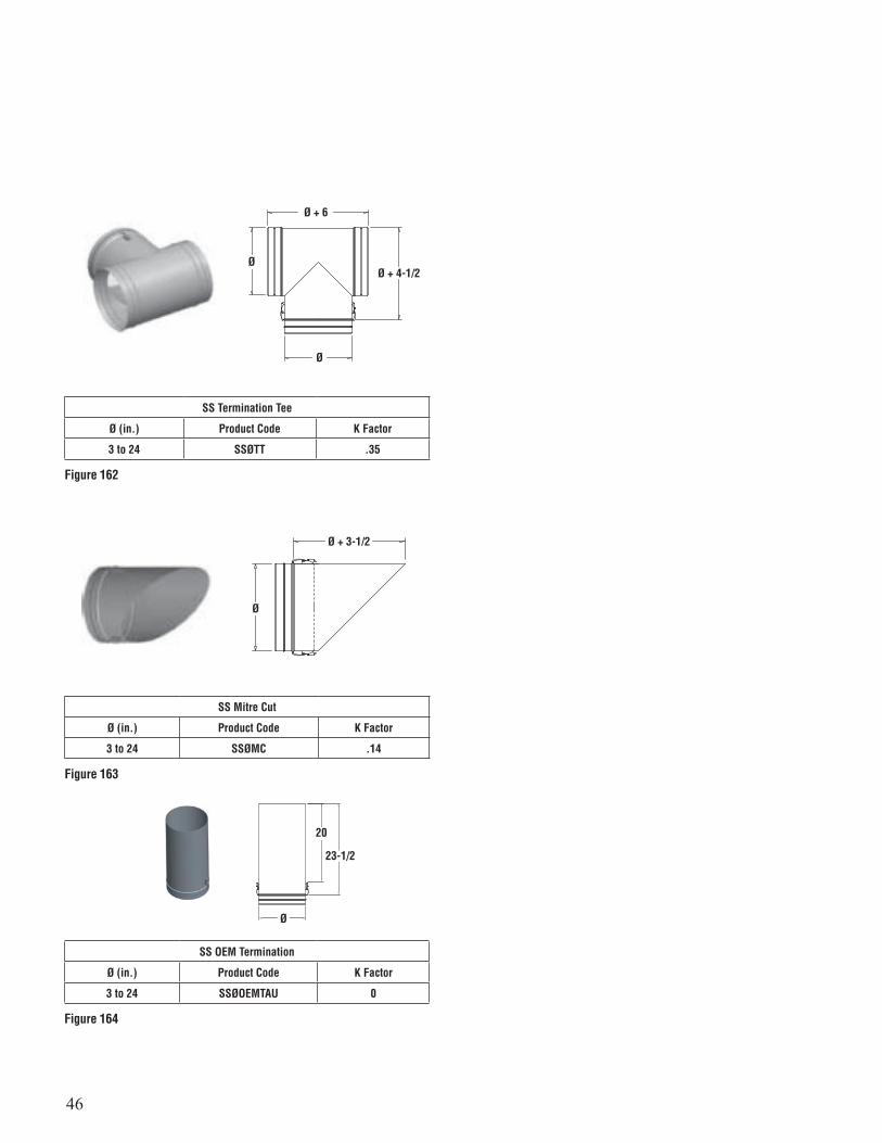
46
Ø
20
23-1/2
SS Termination Tee
Ø (in.) Product Code K Factor
3 to 24 SSØTT .35
Figure 162
Ø
Ø
Ø + 6
Ø + 4-1/2
SS Mitre Cut
Ø (in.) Product Code K Factor
3 to 24 SSØMC .14
SS OEM Termination
Ø (in.) Product Code K Factor
3 to 24 SSØOEMTAU 0
Figure 163
Figure 164
Ø
Ø + 3-1/2

47
SECURITY CHIMNEYS SECURE SEAL 15 YEAR LIMITED WARRANTY
This Security Chimneys 15-year Limited Warranty warrants your Secure Seal gas vent system (Product) to be free from defects in material and workmanship at the time of manufacture. This 15-year Limited Warranty includes all components and fittings. After installation, if covered components manufactured by Security Chimneys are found to be defective in materials or workmanship during the 15-year Warranty period and while the Product remains at the site of the original installation, Security Chimneys will, at its option, replace the covered components. Security Chimneys reserves the right to replace covered components with an equivalent product and the replacement must be carried out in accordance with Security Chimneys recommendations. If replacement is not commercially practical, Security Chimneys will, at its option, refund the purchase price or wholesale price of the Security Chimneys Product, whichever is applicable. Labor or freight costs to remove or replace Security Chimneys components are not included. THERE ARE EXCLUSIONS AND LIMITATIONS to the 15-year Limited Warranty as described herein.COVERAGE COMMENCEMENT DATEWarranty coverage begins on the date of shipment from Security Chimneys to the installation site or project-holding site, whichever is applicable.EXCLUSIONS AND LIMITATIONSThis 15-year Limited Warranty applies only if the Product is installed in the United States or Canada and only if used for the application for which it was designed and intended. The Product must be installed and maintained in accordance with the printed instructions accompanying the Product and in compliance with all applicable installation and building codes and good trade practices. Any repaired or replaced product shall be warranted for the duration of time no longer than the remaining or unexpired term of the original warranty. The warranty period is 15 years from the date of installation when used for venting listed, Category I, II, III or IV gas heating equipment or water heaters that specify this type of venting system.
The 15-Year Limited Warranty is extended to the purchaser subject to the following additional conditions:• The vent system is inspected and maintained annually, beginning one year after the date of installation and continue throughout the warranty period.• Generally accepted engineering practices have been followed to determine that sizing and material specifications are suitable for the application and environment involved.• The components have been correctly installed in accordance with the system design and installation instructions as provided by Security Chimneys
This warranty is non-transferable and extends to the original owner only. The Product must be purchased through an Security Chimneys Agent/Representative and proof of purchase must be provided.
Security Chimneys will not be responsible for: (a) damages caused by normal wear and tear, corrosion from salt air, accident, riot, fire, flood or acts of God; (b) damages caused by abuse, negligence, misuse, or unauthorized alteration or repair of the Product affecting its stability or performance. (c) damages caused by failing to provide proper maintenance and service in accordance with the instructions provided with the Product; (d) damages, repairs or inefficiency resulting from faulty installation or application of the Product.
This 15-year Limited Warranty covers only parts as provided herein. Security Chimneys’ entire liability is limited to the purchase price of this Product. In no case shall Security Chimneys be responsible for materials, components or construction, which are not manufactured or supplied by Security Chimneys or for the labor necessary to install, repair or remove such materials, components or construction. All replacement or repair components will be shipped F.O.B. from the Security Chimneys manufacturing facility.LIMITATION ON LIABILITYIt is expressly agreed and understood that the sole obligation of Security Chimneys and the purchaser’s exclusive remedy under this warranty, under any other warranty, expressed or implied, or in contract, tort or otherwise, shall be limited to replacement, repair, or refund, as specified herein.
In no event shall Security Chimneys be liable for any incidental or consequential damages caused by defects in the Product, whether such damage occurs or is discovered before or after replacement or repair, and whether such damage is caused by Security Chimneys negligence.Security Chimneys makes no expressed warranties except as stated in this 15-year Limited Warranty. The duration of any implied warranty is limited to the duration of this expressed warranty. No one is authorized to change this 15-year Limited Warranty or to create for Security Chimneys any other obligation or liability in connection with the Product. Some states and provinces do not allow the exclusion or limitation of incidental or consequential damages, so the above limitations or exclusions may not apply to you. The provisions of this 15-year Limited Warranty are in addition to and not a modification of or subtraction from any statutory warranties and other rights and remedies provided by law.INVESTIGATION OF CLAIMS AGAINST WARRANTYSecurity Chimneys reserves the right to investigate any and all claims against this 1-Year Standard and 15-year Limited Warranty and to decide, in its sole discretion, upon the method of settlement.
Security Chimneys shall in no event be responsible for any warranty work done by a contractor that is not approved without first obtaining Security Chimneys’ prior written consent.HOW TO REGISTER A CLAIM AGAINST WARRANTYIn order for any claim under this warranty to be valid, you must contact the Security Chimneys Agent/Representative from which you purchased the Product. If you cannot contact the Agent/Representative, then you must notify Security Chimneys in writing. Security Chimneys must be notified of
the claimed defect in writing within 90 days of the date of failure. Notices should be directed to the Security Chimneys Warranty Department.

48
WARRANTY
This product has a 15 year limited warranty. Please read the warranty to be familiar with its coverage.
Retain this manual. File it with your other documents for future reference.
PRODUCT REFERENCE INFORMATION
Please contact Security Chimneys International for the phone number of your nearest Security Chimneys International dealer who will answer your questions or address your concerns.
Normally, all parts should be ordered through your Security Chimneys In-ternational distributor or dealer. Parts will be shipped at prevailing prices at time of order.
When ordering repair parts, always give the following information:
1. The model number of the vent system.2. The part number.3. The description of the part.4. The quantity required.5. The installation date of the chimney system.
If you encounter any problems or have any questions concerning the installation or application of this system, please contact your dealer.
© 2011, 2017 Security Chimneys International, Ltd.
P/N SFSS REV. 11 08-07-19
Security Chimneys International Limited reserves the right to make changes at any time, without notice, in design, materials, specifications, prices. Consult your local distributor for chimney system code information.
2125 MONTEREY ST. • LAVAL, QC., CANADA • H7L 3T6800-667-3387; www.securitychimneys.com