submittal of analytical evaluation of reactor … unit 2 -submittal of analytical evaluation of...
TRANSCRIPT
Exelkn. Exelon Nuclear www exeloncorp corn Nuclear 2o0 Exelon Way
Kennett Square, PA 19348
December 9, 2002
U.S. Nuclear Regulatory Commission Attention: Document Control Desk Washington DC 20555
Peach Bottom Atomic Power Station, Unit 2 Facility Operating License No. DPR- 44 NRC Docket No. 50-277
Subject: Submittal of Analytical Evaluation of Reactor Pressure Vessel Closure Head Indications
Dear Sir/Madam:
In accordance with the ASME Boiler and Pressure Vessel Code, Section XI, IWB-3134(b), Exelon
Generation Company, LLC, is submitting an analytical evaluation of indications identified in the
Peach Bottom Atomic Power Station (PBAPS), Unit 2 reactor pressure vessel (RPV) closure
head.
As a result of Ultrasonic Testing (UT) examinations conducted during the recently concluded
refueling outage at PBAPS, Unit 2, ASME Section Xl reportable indications were identified in a
meridional weld of the reactor pressure vessel closure head. The meridional weld is an
Examination Category B-A, Item No. B1.22 weld, as identified in ASME Section XI, 1989 Edition
(no addenda). The UT examinations were performed in accordance with ASME Section XI,
Appendix VIII, 1995 Edition with the 1996 Addenda, using approved Performance Demonstration
Initiative (PDI) procedures. Analytical evaluation of the reported indications was conducted in
accordance with IWB-3600, as allowed by IWB-3132.4.
Periodic Inservice Inspection (ISI) examinations were initially conducted on six (6) meridional
welds and one (1) circumferential weld on the vessel closure head and on two (2) meridional
welds on the bottom head. As a result of the reportable indications identified in one (1)
meridional closure head weld, additional examinations were performed in accordance with ASME
Section XI, IWB-2430(a). This additional scope included manual UT examination on four (4)
additional meridional welds in the reactor vessel bottom head.
The results of all RPV head weld examinations identified sixteen (16) reportable indications in one
(1) weld in the closure head (weld CH-MB). These indications did not meet the ASME Section XI
acceptance standards as specified in Table IWB-3510-1. No reportable indications were
identified in the other RPV head welds. Based on the analytical evaluation provided in the - Iq-7
PBAPS, Unit 2 - Submittal of Analytical Evaluation of Reactor Pressure Vessel Closure Head Indications Analytical Evaluation December 9, 2002 Page 2
attachment, it is concluded that the indications found in the PBAPS, Unit 2 vessel closure head,
during the most recently concluded refueling outage, are acceptable by the flaw acceptance
criteria of IWB-3600 of the ASME Section XI Code.
If you have any questions, please do not hesitate to contact us.
Sincerey
Michael P. Gallagher Director, Ucensing and Regulatory Affairs Mid-Atlantic Regional Operating Group
Attachment
cc: H. J. Miller, Administrator, Region I, USNRC A. C. McMurtray, USNRC Senior Resident Inspector, PBAPS J. Boska, Senior Project Manager, USNRC
GENE 0000-0007-9747, Rev. 1
THE EVALUATION OF INDICATIONS IN PEACH BOTTOM UNIT 2 VESSEL CLOSURE HEAD FOR
CONTINUED OPERATION
September 2002
Prepared by: 5 • / A S. Kleinsmitl, E Structural Mechanics & Materials
Verified by: 4 1 .Nb~ H.S. Mehta, Engineering Fellow Structural Mechanics & Materials
Approved by: 6z- )7 /,/, R.M. Horn, Manager Structural Mechanics & Materials
Oonnorf
i

GENE 0000-0007-9 74 7, Rev. 1
DISCLAIMER OF RESPONSIBILITY
Important Notice Regarding the Contents of this Report
Please Read Carefully
The only undertakings of the General Electric Company (GE) respecting
information in this document are contained in the contract between Exelon
Corporation and GE, Purchase Order 01026357 Revision 5, effective 8/28/02, as
amended to the date of transmittal of this document, and nothing contained in this
document shall be construed as changing the contract. The use of this
information by anyone other than Exelon Corporation, or for any purpose other
than that for which it is furnished by GE, is not authorized; and with respect to
any unauthorized use, GE makes no representation or warranty, express or
implied, and assumes no liability as to the completeness, accuracy, or usefulness
of the information contained in this document, or that its use may not infringe privately owned rights.
Copyright, General Electric Company, 2002.
ii

GENE 0000-0007-9747, Rev. I
Table of Contents
Subiect Pa2e No.
1. EXECUTIVE SUMMARY ....................................................................................... 1 1.1. R EFEREN CE .................................................................................................................................. 1
2. INTRODUCTION AND REPORT OUTLINE ................................................... 2 2.1. REFERENCE .................................................................................................................................. 2
3. UT INSPECTION RESULTS & FLAW GEOMETRY FOR EVALUATION ........ 4 3.1. UT INSPECTION RESULTS ................................................................................................... 4
3.2. FLAW GEOMETRIES CONSIDERED IN EVALUATION .................................................... 4
3.3. FABRICATION REVIEW ........................................................................................................ 5
3.4. REFERENCES ............................................................................................................................... 5
4. FRACTURE MECHANICS EVALUATION ..................................................... 12 4.1. ASSUMPTIONS ........................................................................................................................... 12
4.2. APPLIED AND WELD RESIDUAL STRESSES .................................................................. 12
4.3. K CALCULATION METHODOLOGY ................................................................................... 13
4.4. FATIGUE CRACK GROWTH ............................................ 14
4.5. ALLOWABLE K VALUES .............................................. 14
4.6. DISPOSITION OF INDICATIONS .......................................................................................... 15
4.7. REFERENCES .................... ................................... 16
5. SUMMARY AND CONCLUSIONS ................................................................. 20
APPEND IX A ..................................................................................................................... A
APPENDIX B ............................................................................................................ B
iii
GENE 0000-0007-9747, Rev. I
1. EXECUTIVE SUMMARY
The reactor pressure vessel closure head at Peach Bottom Atomic Power Station, Unit 2 (PBAPS-2) was ultrasonically examined during refueling outage fourteen (2R-14). Each of the six meridional welds was examined. Several indications were noted at these welds. Other than the CH-MB weld, the detected indications at the other meridional welds were acceptable as-is by the acceptance standards IWB-35 10 of ASME Section XI (1989 Edition without Addenda). At the CH-MB weld numerous recordable indications were noted out of which eighteen (18) indications/flaws displayed tip signals and possessed a through-wall dimension. Sixteen (16) of these flaws did not meet the acceptance standards. The Section XI Code allows for the acceptance of such flaws for continued service if they meet the requirements of Paragraph IWB-3600, Analytical Evaluation of Flaws. The analysis involves the use of fracture mechanics procedures in accordance with Appendix A of Section XI. The objective of this report is to document the results of such evaluation.
The use of surface proximity rules of Section XI indicated that all sixteen (16) indications need to be characterized as surface flaws for the purposes of fracture mechanics evaluation. Two conditions were determined to be governing: bolt-up and system pressure test. The bounding membrane and bending stress values for the fracture mechanics evaluation for the two conditions were obtained through a review of previous
stress analyses of the closure heads. The bolt-up temperature was assumed as 70'F [1-1 & 1-2] at a pressure of 0 psi and the pressure test temperature was assumed as 169°F [11] with a pressure of 1050 psi [1-1]. The stress intensity factors for the characterized surface flaws were calculated for various flaw depth (a) to flaw length (0) ratios (or, aspect ratios). It was determined that the pressure-test condition was governing. The limiting flaw was found to be acceptable per ASME Section XI Code even after accounting for projected crack growth fori the life of the plant including license renewal (60 total years).
Based on this evaluation it is concluded that all of the indications found in PBAPS-2 vessel closure head during Refueling Outage (2R-14) are acceptable by the flaw acceptance criteria of the ASME Section XI Code.
1.1. REFERENCE
[1-1] Exelon Nuclear, Peach Bottom Unit 2, Surveillance Test Specification ST-O-080680-2, Rev. 6: Reactor Pressure Vessel (Class 1) Hydrostatic Pressure Test.
[1-2] PECO Energy Company, Peach Bottom Unit 2, Surveillance Test Specification ST-O-080-500-2, Rev. 7: Recording and Monitoring Reactor Vessel Temperature and Pressure.
I
I
GENE 0000-0007-9747, Rev. I
2. INTRODUCTION AND REPORT OUTLINE
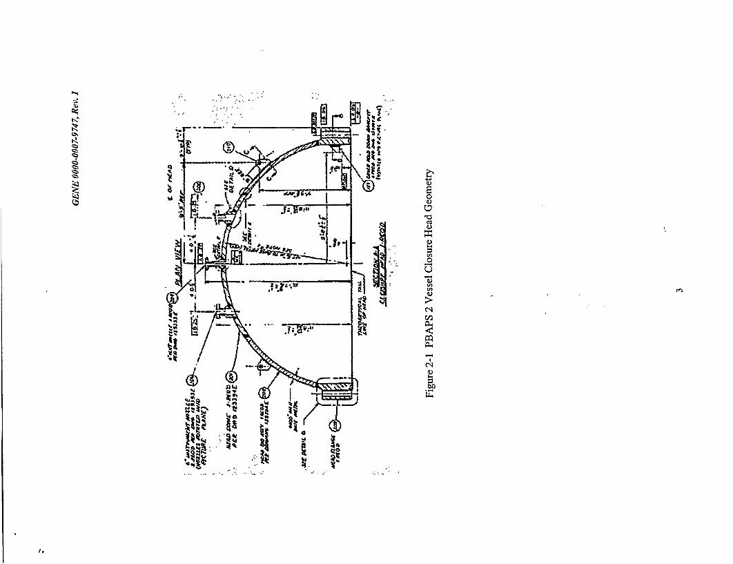
The reactor pressure vessel closure head at Peach Bottom, Unit 2 (PBAPS-2) was ultrasonically examined during the 2R14 refueling outage. Figure 2-1 shows the geometry of the vessel head. The inside radius of the head is 125.69 inches and the minimum specified thickness is 4.00 inches [2-1]. However, the measured thickness reported during the UT examination is 4.25 inches, the value used in the evaluations conducted for this report [2-2]. The inside surface of the closure head is unclad. Meridional welds were examined. Several flaws were noted in the meridional weld CHMB. All of the flaws are not ID connected (i.e. sub surface) as confirmed by surface examination conducted at the ID surface. However, portions of the flaws are less than 0.4d from the ID surface, thus they were classified as surface flaws for fracture mechanics analysis. The observed flaws were first characterized and compared with the acceptance standards provided in Table IWB-3500-1 of Section XI, ASME Code [2-3]. Some of the flaws did not meet the acceptance standards. Section XI, subparagraph IWB-3132.4 allows for the acceptance of such flaws for continued service if they meet the requirements of Paragraph IWB-3600, Analytical Evaluation of Flaws. The analysis involves the use of fracture mechanics procedures in accordance with Appendix A of Reference 2-3. The objective of this report is to document the results of such evaluation.
Section 3 of this report summarizes UT inspection results and describes the flaw geometries considered in the evaluation. The results of the fracture mechanics evaluation are presented in Section 4. A comparison with the allowable flaw values is presented. Finally, summary and conclusions are presented in Section 5.
2.1. REFERENCE
[2-1] Babcock & Wilcox CO. Pressure Boundary Drawing, "Closure Head Assembly" for Peach Bottom Unit 2, Drawing # 129392 E R7, GE VPF# 1896-67-8.
[2-2] GE Nuclear Energy, Peach Bottom Unit 2 - 2R14 UT Examination Report # 008900 for Weld ID - CH-MB Meridional Weld @ 60 Degrees. September 27, 2002.
[2-3] ASME Boiler and Pressure Vessel Code, Section XI, Rules for In-Service Inspection of Nuclear Power Plant Components, ASME, 1989 Edition without Addenda.
2
q6)
14
1,
0
cn
V
Cl
Cl V I-
GENE 0000-0007-9747, Rev. I
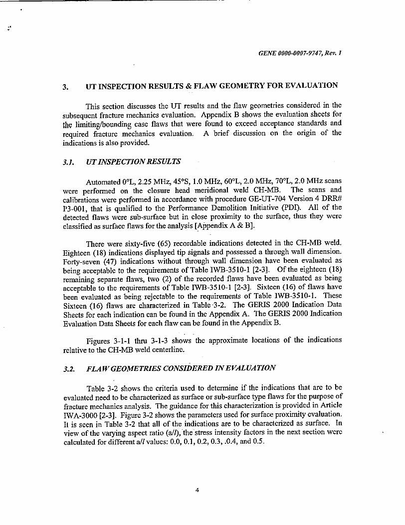
3. UT INSPECTION RESULTS & FLAW GEOMETRY FOR EVALUATION
This section discusses the UT results and the flaw geometries considered in the subsequent fracture mechanics evaluation. Appendix B shows the evaluation sheets for the limiting/bounding case flaws that were found to exceed acceptance standards and
required fracture mechanics evaluation. A brief discussion on the origin of the indications is also provided.
3.1. UTINSPECTIONRESULTS
Automated 00L, 2.25 MHz, 45*S, 1.0 MHz, 60'L, 2.0 MHz, 70'L, 2.0 MHz scans were performed on the closure head meridional weld CH-MB. The scans and calibrations were performed in accordance with procedure GE-UT-704 Version 4 DRR# P3-001, that is qualified to the Performance Demolition Initiative (PDI). All of the detected flaws were sub-surface but in close proximity to the surface, thus they were classified as surface flaws for the analysis [Appendix A & B].
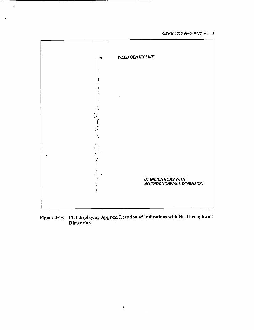
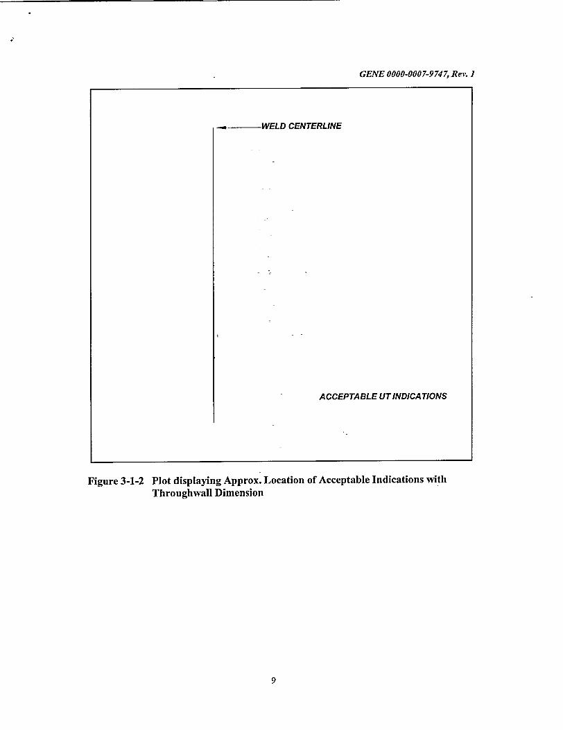
There were sixty-five (65) recordable indications detected in the CH-MB weld. Eighteen (18) indications displayed tip signals and possessed a through wall dimension. Forty-seven (47) indications without through wall dimension have been evaluated as being acceptable to the requirements of Table IWB-3510-1 [2-3]. Of the eighteen (18) remaining separate flaws, two (2) of the recorded flaws have been evaluated as being acceptable to the requirements of Table IWB-3510-1 [2-3]. Sixteen (16) of flaws have been evaluated as being rejectable to the requirements of Table IWB-3510-1. These Sixteen (16) flaws are characterized in Table 3-2. The GERIS 2000 Indication Data Sheets for each indication can be found in the Appendix A. The GERIS 2000 Indication Evaluation Data Sheets for each flaw can be found in the Appendix B.
Figures 3-1-1 thru 3-1-3 shows the approximate locations of the indications relative to the CH-MB weld centerline.
3.2. FLAW GEOMETRIES CONSIDERED INEVALUATION
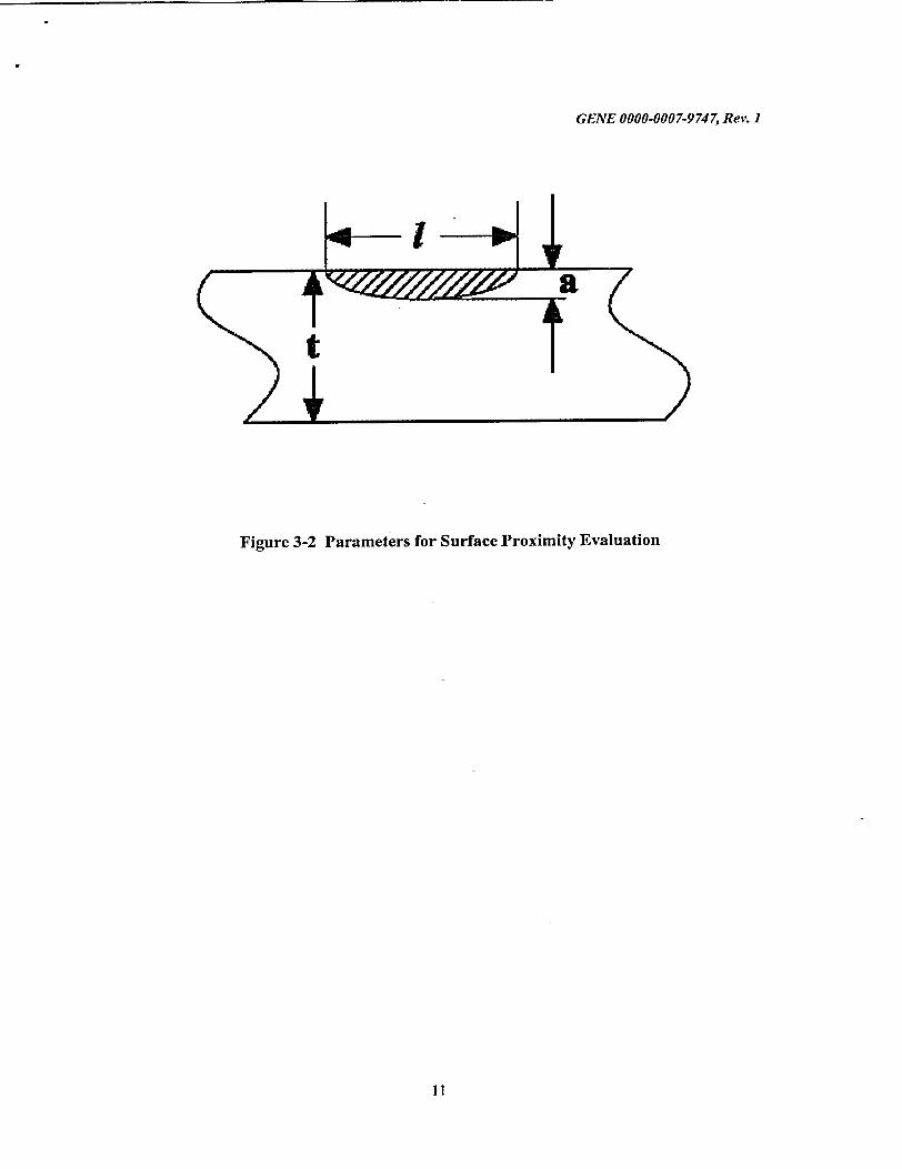
Table 3-2 shows the criteria used to determine if the indications that are to be evaluated need to be characterized as surface or sub-surface type flaws for the purpose of fracture mechanics analysis. The guidance for this characterization is provided in Article IWA-3000 [2-3]. Figure 3-2 shows the parameters used for surface proximity evaluation. It is seen in Table 3-2 that all of the indications are to be characterized as surface. In view of the varying aspect ratio (a/), the-stress intensity factors in the next section were calculated for different a/l values: 0.0, 0.1, 0.2, 0.3, .0.4, and 0.5.
4
GENE 0000-0007-9 74 7, Rev. 1
3.3. FABRICATION REVIEW
All the indications in question-are sub surface, in close proximity to the surface and are not service induced, but were 'considered as surface flaws for the fracture mechanics evaluation. A fabrication review (Reference 3-1) concluded the following:
"* The flaws detected during 2R14 have existed since the closure head was fabricated.
"* These flaws do not indicate "abnormal degradation of the pressure boundary" as defined by the USNRC.
"* These flaws should be considered newly discovered flaws, rather than newly developed flaws.
Indications at vessel welds of the type seen in the Peach Bottom Unit 2 top head welds are not uncommon and have been found in other reactor pressure vessel welds in other plants. In most cases, the new finding is attributed to the ability of current UT techniques to detect flaws that would have been undetectable using inspection techniques available during the time of fabrication of the Peach Bottom vessel. Thus, as long as the required fracture margins are demonstrated, the indications are judged to be benign and have no impact on structural integrity.
3.4. REFERENCES
[3-1] Miller, W.F., "Investigation into the Origin of Ultrasonic Indications in RPV Closure Head Welds for the Peach Bottom 2R14 Outage," GE Report No. GENE955-004-0902 Rev. 1, September 2002.
5

GENE 0000-0007-9747, Rev. I
Table 3-1 Listing of Ultrasonic Indications in RPV Closure Head Weld CH
MB at Peach Bottom Unit 2
Number of Number of Acceptable per
Weld ID Location Recordable Indications / flaws Table IWB-3510-1 Indications with through wall
dimension
CH-MB 600 Azimuth 65 18 2 (See description (#10 & #39)
below)
CH-MB
IND # 5 Flaw length = 0.75" Flaw depth (a) = 0.17" S = 0"
IND # 6 Flaw length = 1.00" Flaw depth (a) = 0.20" S = 0"
IND# 10
IND # 14
IND# 16
IND # 20
IND # 24
IND # 34
IND #38
IND #39
IND #42
IND # 44
IND # 50
IND # 53
IND # 56
IND # 57
IND #61
IND # 63
Flaw length = 0.75"
Flaw length = 1.75"
Flaw length = 3.75"
Flaw length = 1.25"
Flaw length = 1.00"
Flaw length = 0.75"
Flaw length = 0.75"
Flaw length = 0.40"
Flaw length = 1.75"
Flaw length = 0.75"
Flaw length = 1.00"
Flaw length = 0.75"
Flaw length = 1.00"
Flaw length = 1.00"
Flaw length = 1.00"
Flaw length = 1.50"
Flaw depth (a) = 0.10"
Flaw depth (a) = 0.16"
Flaw depth (a) = 0.25"
Flaw depth (a) = 0.17"
Flaw depth (a) = 0.17"
Flaw depth (a) = 0.16"
Flaw depth (a) = 0.19"
Flaw depth (a) = 0.16"
Flaw depth (a) = 0.19"
Flaw depth (a) = 0.17"
Flaw depth (a) = 0.12"
Flaw depth (a) = 0.14"
Flaw depth (a) = 0.17"
Flaw depth (a) = 0.17"
Flaw depth (a) = 0.12"
Flaw depth (a) = 0.17"
Note: Values reported are taken directly from Appendix A & B.
6
S 00"
S =0"
S = 0"
S =0"
S Oi0"
S = 0"
S =0",
S = 0"
S = 0"
S =0"
S =0"
S = 0"l
S = 0"l
S = 0"l
S = 0"l
S = 0"

GENE 0000-0007-9 74 7, Rev. 1
Table 3-2 Characterization of Flaws
Weld ID IND # I (in.) a (in.) S (in.) S<0.4a* all
CH-MB 5 0.75 0.17 0.0 Yes 0.2267 CH-MB 6 1.00 0.20 0.0 Yes 0.2
CH-MB 10 0.75 0.10 0.0 Yes 0.1334
CH-MB 14 1.75 0.16 0.0 Yes 0.0914
CH-MB 16 3.75 0.25 0.0 Yes 0.0667 CH-MB 20 1.25 0.17 0.0 Yes 0.136 CH-MB 24 1.00 0.17 0.0 Yes 0.17
CH-MB 34 0.75 0.16 0.0 Yes 0.2133 CH-MB 38 0.75 0.19 0.0 Yes 0.2534
CH-MB 39 0.40 0.16 0.0 Yes 0.4 CH-MB 42 1.75 0.19 0.0 Yes 0.1086 CH-MB 44 0.75 0.17 0.0 Yes 0.2267
CH-MB 50 1.00 0.12 0.0 Yes 0.12
CH-MB 53 0.75 0.14 0.0 Yes 0.1867
CH-MB 56 1.00 0.17 0.0 Yes 0.17 CH-MB 57 1.00 0.17 0.0 Yes 0.17
CH-MB 61 1.00 0.12 0.0 Yes 0.12
CH-MB 63 1.50 0.17 0.0 Yes 0.1134
* Flaw characterized as surface flaw if S < 0.4a.
7
GENE 0000-0007-9 74 7, Rev. 1
Figure 3-1-1 Plot displaying Approx. Location of Indications with No Throughwall Dimension
8
-..m WELD CENTERLINE
I,
Ii
UT INDICATIONS WITH NO THROUGH WALL DIMENSION
GENE 0000-0007-9747, Rev. 1
Figure 3-1-2 Plot displaying Approx. Location of Acceptable Indications with Throughwall Dimension
9
-. WELD CENTERLINE
ACCEPTABLE UT INDICATIONS

I'-PNIT 1fnlfn Mfn7 0747 DV,,
Figure 3-1-3 Plot displaying Approx. Location of Unacceptable UT Indications with Throughwall Dimension
10
-. u-- WELD CENTERLINE
UNA CCEPTABLE UT INDICATIONS
GENE 0000-0007-9 74 7, Rev. 1
Figure 3-2 Parameters for Surface Proximity Evaluation
11
GENE 0000-0007-9747, Rev. I
4. FRACTURE MECHANICS EVALUATION
The fracture mechanics evaluation was conducted for several surface flaw shape geometries using the procedures outlined in Appendix A of Section XI [4-1]. Two conditions were found to be limiting for the determination of allowable flaw sizes: (1) bolt-up, and (2) system pressure test.
4.1. ASSUMPTIONS
The following values were used for the pressure and temperature conditions during the bolt-up and system pressure test conditions. These values remain unchanged for power uprate conditions, but can change when new PT curves are licensed.
* The bolt-up temperature is 70'F [4-2 & 4-3]. * The pressure test pressure and temperature are 1050 psi and 169°F [4-4]. * The limiting RTNDT value for the closure head side plate (torus) region is 10'F.
[4-3]
The number of bolt-up, pressure test and start up-shut down events assumed in the fatigue crack growth calculation was based on [Reference 4-5], and is discussed in Subsection 4.4.
4.2. APPLIED AND WELD RESIDUAL STRESSES
The applied stresses in the vessel closure head to flange region are primarily from the following sources: bolt preload, internal pressure and weld residual stress. The internal pressure is zero during the bolt-up. Since all of the flaws are in the meridional direction welds, the circumferential or hoop stress is of interest for the purpose of this evaluation. Due to the complex geometry of the flange region, only a detailed finite element analysis of PBAPS Unit 2 closure head geometry can provide a complete picture of the stress distribution due to bolt-up and internal pressure. Since such an analysis was unavailable, the results from finite element analyses conducted for other BWR vessels of similar size on file with GENE were reviewed to conservatively determine a set of membrane and bending stresses. The determination took into account the differences in the R/t ratios between the available finite element model geometry and the PBAPS, Unit 2 closure head geometry.
During bolt-up large hoop bending stresses are introduced in the head near the flange junction but they attenuate rapidly as one moves away from the flange meridionally. These bending stresses are compressive at the ID surface near the flange junction. The hoop membrane stress is tensile but attenuates less rapidly. The longest
12
GENE 0000-0007-9747, Rev. 1
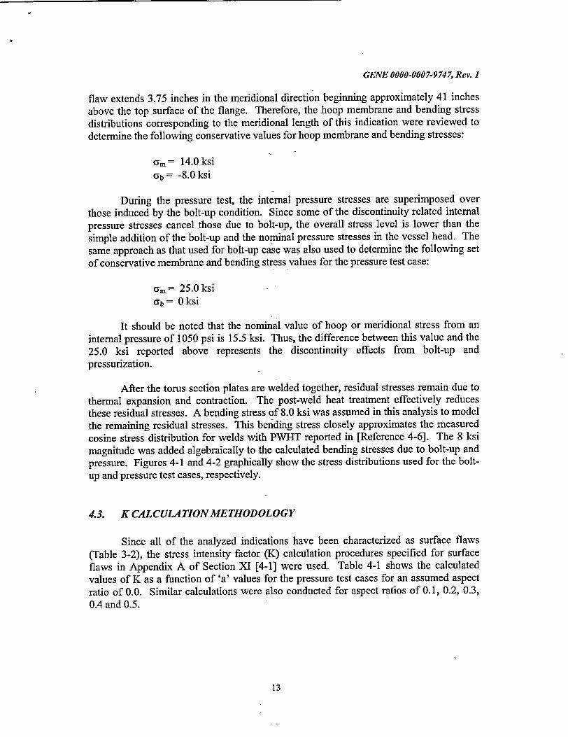
flaw extends 3.75 inches in the meridional direction beginning approximately 41 inches above the top surface of the flange. Therefore, the hoop membrane and bending stress distributions corresponding to the meridional length of this indication were reviewed to determine the following conservative values for hoop membrane and bending stresses:
am= 14.0 ksi 9b = -8.0 ksi
During the pressure test, the internal pressure stresses are superimposed over those induced by the bolt-up condition. Since some of the discontinuity related internal pressure stresses cancel those due to bolt-up, the overall stress level is lower than the simple addition of the bolt-up and the nominal pressure stresses in the vessel head. The same approach as that used for bolt-up case was also used to determine the following set of conservative membrane and bending stress values for the pressure test case:
am = 25.0 ksi Ub = 0 ksi
It should be noted that the nominal value of hoop or meridional stress from an internal pressure of 1050 psi is 15.5 ksi. Thus, the difference between this value and the 25.0 ksi reported above represents the discontinuity effects from bolt-up and pressurization.
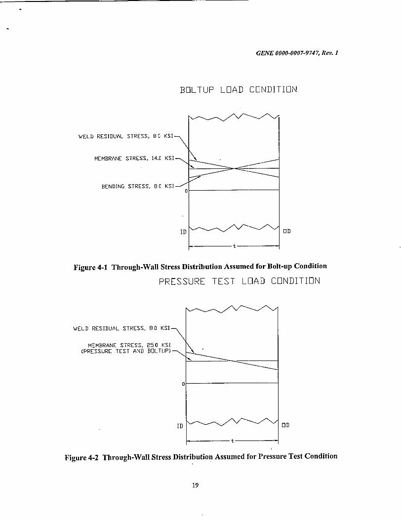
After the torus section plates are welded together, residual stresses remain due to thermal expansion and contraction. The post-weld heat treatment effectively reduces these residual stresses. A bending stress of 8.0 ksi was assumed in this analysis to model the remaining residual stresses. This bending stress closely approximates the measured cosine stress distribution for welds with PWHT reported in [Reference 4-6]. The 8 ksi magnitude was added algebraically to the calculated bending stresses due to bolt-up and pressure. Figures 4-1 and 4-2 graphically show the stress distributions used for the boltup and pressure test cases, respectively.
4.3. K CALCULA TIONMETHODOLOGY
Since all of the analyzed indications have been characterized as surface flaws (Table 3-2), the stress intensity factor (K) calculation procedures specified for surface flaws in Appendix A of Section XI [4-1] were used. Table 4-1 shows the calculated values of K as a function of 'a' values for the pressure test cases for an assumed aspect ratio of 0.0. Similar calculations were also conducted for aspect ratios of 0.1, 0.2, 0.3, 0.4 and 0.5.
13

GENE 0000-0007-9747, Rev. I
4.4. FATIGUE CRACK GROWTH
Since all the flaws are characterized as surface flaws, they are assumed as being
exposed to the reactor water environment. Thus, the crack growth analysis was
performed using the Section XI fatigue crack growth rates for water environment.
The current analyzed reactor pressure vessel cycles for the 40-year design life are
listed in [Reference 4-5]. Only the bolt-up (66), hydrostatic test (130) and heatup
cooldown (161) events are significant from the perspective of fatigue crack growth in the
vessel closure head. The stress range for the heatup-cooldown cycle is bounded by that
for the pressure test, and therefore, the cycles for the two events were lumped together for the fatigue crack growth calculation purposes. The number of cycles for these events were increased by 50% to account for operation during the license renewal period. Thus, the number of events assumed for the bolt-up were 66xl.5 or 100. The number of events
assumed for the pressure test were {(130+161)xl.5} or - 440. This approach is
conservative since it does not take any credit for the number of cycles already used so far. The highest applied K values listed in Tables 4-2 and 4-3 were used for the fatigue
crack growth calculations. The predicted crack growth was calculated as 56.2 micro inches per cycle. Which results in a crack growth of 0.025" for 440 cycles.
4.5. ALLOWABLE K VALUES
The first step in the allowable flaw calculation is to determine the Kia value at the
temperature appropriate for the operating condition being analyzed. The 1989 version of Section XI [4-1] does not provide an explicit mathematical equation for the calculation of
Kia at a given temperature and RTNDT. However, Reference 4-7 gives the following
equation that was used to calculate the KIa curve given in Figure A-4200-1[4-1]:
Kia = 26.78 + 1.233 * Exp ( 0.0145 * ( T - RTNDT + 160))
where, T and RTNDT are in 'F and Kia is in ksi4in.
Paragraph IWB-3613 of Section XI [4-1] also indicates that for flange region a
safety factor of 42 can be used for bolt-up condition. Thus, a safety factor of 42 was
used for the bolt-up condition to obtain KIa allowable. For the pressure test condition, a
safety factor of 410 was used as specified in IWB-3613[4-1]. The following summarizes the numerical values:
14
GENE 0000-0007-9747, Rev. 1
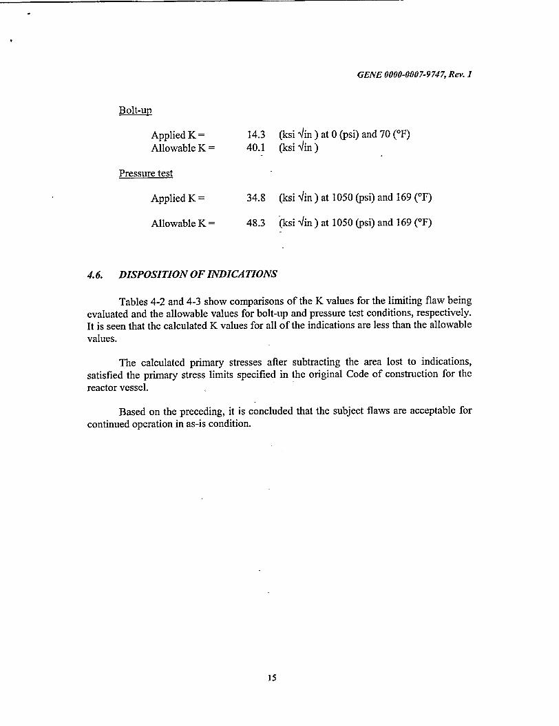
Bolt-up
Applied K = Allowable K =
14.3 40.1
(ksi 4lin ) at 0 (psi) and 70 ('F) (ksi qin )
Pressure test
Applied K =
Allowable K =
34.8 (ksi 'uin) at 1050 (psi) and 169 ('F)
48.3 (ksi 4 in) at 1050 (psi) and 169 ('F)
4.6. DISPOSITION OF INDICATIONS
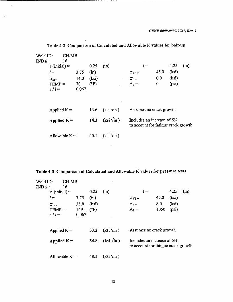
Tables 4-2 and 4-3 show comparisons of the K values for the limiting flaw being evaluated and the allowable values for bolt-up and pressure test conditions, respectively. It is seen that the calculated K values for all of the indications are less than the allowable values.
The calculated primary stresses after subtracting the area lost to indications, satisfied the primary stress limits specified in the original Code of construction for the reactor vessel.
Based on the preceding, it is concluded that the subject flaws are acceptable for continued operation in as-is condition.
15
GENE 0000-0007-9747, Rev. I
4.7. REFERENCES
[4-1] ASME Boiler and Pressure Vessel Code, Section XI, Rules for In-Service Inspection of Nuclear Power Plant Components, ASME, 1989 Edition without Addenda.
[4-2] PECO Energy Company, Peach Bottom Unit 2, Surveillance Test Specification ST-O-080-500-2, Rev. 7: Recording and Monitoring Reactor Vessel Temperature and Pressure.
[4-3] L. Tilly, "Pressure-Temperature Curves for Exelon Peach Bottom Unit 2" GE Nuclear Energy, San Jose, CA, GE-NE-B13-02118-00-01 Rev. 0, September 2002.
[4-4] Exelon Nuclear, Peach Bottom Unit 2, Surveillance Test Specification ST-O-080680-2, Rev. 6: Reactor Pressure Vessel (Class 1) Hydrostatic Pressure Test.
[4-5] PECO Energy Company, Peach Bottom Unit 2, Surveillance Test Specification ST-O-080-940-2, Rev. 6: Reactor Pressure Vessel Transients Cycles Record.
[4-6] D.A. Ferrill, et al, "Measurement of Residual Stresses in Heavy Weldment," Welding Journal Research Supplement, Vol 45, Nov. 1966.
[4-7] EPRI Report No. NP-719-SR, "Flaw Evaluation Procedures: ASME Section XI," August 1978.
16

GENE 0000-0007-9747, Rev. I
Table 4-1 Calculated K values for Pressure test Cases
Calculation of Stress Intensities (ksi-sqrt[in])
0.25 (in)
3.75 (in)
25.0 (ksi)
UYS =
•b =
4.25 (in)
45.0 (ksi)
8.0 (ksi)
Ap a/i Q Mm Mb Km Kb KToTAL A K (psi) (ksi) (ksi) (ksi) (ksi)
1050 0.0 0.879 1.147 1.057 27.100 7.991 35.091 27.100
1050 0.1 0.989 1.117 1.016 24.889 7.242 32.131 24.889 1050 0.2 1.212 1.105 0.985 22.236 6.340 28.577 22.236
1050 0.3 1.521 1.10 0.963 19.740 5.538 25.277 19.740 1050 0.4 1.904 1.10 0.953 17.660 4.896 22.556 17.660
1050 0.5 2.356 1.10 0.937 15.880 4.329 20.209 15.880
17
I =
am =
GENE 0000-0007-9747, Rev. I
Table 4-2 Comparison of Calculated and Allowable K values for bolt-up
Weld ID: CHIND #: 16
a (initial) =
1= am =
TEMP =
a/l=
MB
0.25 3.75 (in)
14.0 70 0.067
(ksi) (OF)
(in)Gy5 =
Yb =
Ap =
4.25 (in) 45.0 (ksi) 0.0 (ksi) 0 (psi)
Applied K =
Applied K =
Allowable K =
13.6 (ksi q/in) Assumes no crack growth
14.3 (ksi 4in) Includes an increase of 5% to account for fatigue crack growth
40.1 (ksi-qin)
Table 4-3 Comparison of Calculated and Allowable K values for pressure tests
Weld ID: CH-MB IND#: 16
A (initial) =
I = 3.75
CYm = 25.0 TEMP= 169 a/l= 0.067
Applied K =
Applied K =
Allowable K =
0.25 (in)
(in)
(ksi) (OF)
'ys =
Gb =
4.25 (in) 45.0 (ksi) 8.0 (ksi) 1050 (psi)
33.2 (ksi 4in ) Assumes no crack growth
34.8 (ksi 'lin ) Includes an increase of 5% to account for fatigue crack growth
48.3 (ksihin)
18
GENE 0000-000 7-9 74 7, Rev. I
BE]LTUP LOAD CONDITION
WELD RESIDUAL STRESS, 80 KSI
MEMBRANE STRESS, 14.0 KSI
BENDING STRESS, 80 KSI-0
ID OlD
t
Figure 4-1 Through-Wall Stress Distribution Assumed for Bolt-up Condition
PRESSURE TEST LOAD CONDITION
WELD RESIDUAL STRESS, 80 KSI
MEMBRANE STRESS, 250 KSI (PRESSURE TEST AND B!LTUP)-ý, V
ID O]D
t
Figure 4-2 Through-Wall Stress Distribution Assumed for Pressure Test Condition
19
I
U

GENE 0000-0007-9747, Rev. 1
5. SUMMARY AND CONCLUSIONS
The reactor pressure vessel closure head at Peach Bottom Atomic Power Station, Unit 2 (PBAPS-2) was ultrasonically examined during refueling outage fourteen (2R-14). Each of the six meridional welds was examined. Several indications were noted at these welds. Other than the CH-MB weld, the detected indications at the other meridional welds were acceptable as-is by the acceptance standards IWB-3510 of ASME Section XI (1989 Edition without Addenda). At the CH-MB weld numerous recordable indications were noted out of which eighteen (18) indications/flaws displayed tip signals and possessed a through-wall dimension. Sixteen (16) of these flaws did not meet the acceptance standards. The Section XI Code allows for the acceptance of such flaws for continued service if they meet the requirements of Paragraph IWB-3600, Analytical Evaluation of Flaws. The analysis involves the use of fracture mechanics procedures in accordance with Appendix A of Section XI. The objective of this report is to document the results of such evaluation.
The use of surface proximity rules of Section XI indicated that all sixteen (16) indications need to be characterized as surface flaws for the purposes of fracture mechanics evaluation. Two conditions were determined to be governing: bolt-up and system pressure test. The bounding membrane and bending stress values for the fracture mechanics evaluation for the two conditions were obtained through a review of previous stress analyses of the closure heads. The bolt-up temperature was assumed as 701F at a pressure of 0 psi and the pressure test temperature was assumed as 169°F with a pressure of 1050 psi. The stress intensity factors for the characterized surface flaws were calculated for various flaw depth (a) to flaw length (0) ratios (or, aspect ratios). It was determined that the pressure-test condition was governing. The limiting flaw was found to be acceptable per ASME Section XI Code even after accounting for projected crack growth for the life of the plant including license renewal (60 total years).
Based on this evaluation it is concluded that all of the indications found in PBAPS-2 vessel closure head during Refueling Outage (2R-14) are acceptable by the flaw acceptance criteria of the ASME Section XI Code.
20

GENE 0000-0007-9747, Rev. 1
APPENDIX A
GERIS 2000 Indication Data Sheets
Rev 1 September 2002
(Includes 2 Appended Pages September 27, 2002)
A
Sep 27 02 11:31a Richard Keck 717 456 4151 P. 2
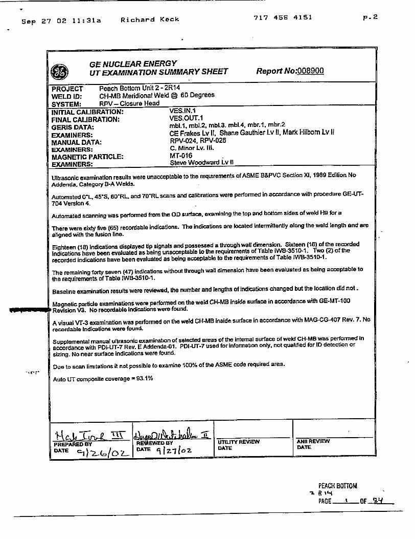
GE NUCLEAR ENERGY UTEXAMINATION SUMMARY SHEET Report No:008900
PROJECT Peach Bottom Unit 2 - 2R14 WELD ID: CH-MB Meridional Weld @ 60 Degrees SYSTEM: RPV- Closure Head
INITIAL CALIBRATION: VES.IN.1
FINAL CALIBRATION: VES.OUT.1 GERIS DATA: mbl.1, mbl.2, mbl.3. mbl.4, mbr.1, mbr.2
EXAMINERS: CE Frakes Lv II, Shane Gauthier Lv II, Mark Hilbom Lv II
MANUAL DATA: RPV-024. RPV-026
EXAMINERS: C. Minor Lv. Ill.
MAGNETIC PARTICLE: MT-016
EXAMINERS: Steve Woodward Lv II
Ultrasonic examination results were unacceptable to the requirements of ASME B&PVC Section XI, 1989 Edition No
Addenda, Category B-A Welds.
Automated O0L, 45"S, 60"RL. and 70"RL scans and calibrations were performed in accordance with procedure GE-UT
704 Version 4.
Automated scanning was performed from the OD surface, examining the top and bottom sides of weld H9 for a
There were sixty five (65) recordable indications. The indications are located intermittently along the weld length and are
aligned with the fusion line.
Eighteen (18) indications displayed tip signals and possessed a through wall dimension. Sixteen (16) of the recorded
Indications have been evaluated as being unacceptable to the requirements of Table IWB-3510-1. Two (2) of the
recorded indications have been evaluated as being acceptable to the requirements of Table IWB-3510-1.
The remaining forty seven (47) indications without through wall dimension have been evaluated as being acceptable to
the requirements of Table IWB-351 0-1.
Baseline examination results were reviewed, the number and lengths of indications changed but the location did not.
Magnetic particle examinations were performed on the weld CH-MB Inside surface in accordance with GE-MT-1 00
Revision V3. No recordable indications were found.
A visual V17-3 examination was performed on the weld CH-MB inside surface in accordance with MAG-CG-407 Rev. 7. No
recordable Indications were found.
Supplemental manual ultrasonic examination of selected areas of the internal surface of weld CH-MB was performed In
accordance with PDI-UT-7 Rev. E Addenda-01. PDI-UT-7 used for Information only, not qualified for ID detection or
sizing. No near surface indications were found.
Due to scan limitations it not possible to examine 100% of the ASME code required area.
Auto UT composite coverage = 93.1%
PREPARED BY RL=AEWED BY UTLIITY REVIEW INil REVIEW
PEACH BOTTOM
PACE OF

P. 3
Richard Keck 717 456 4151
E GERIS 2000 Indication GE Nuclear Energy Data Sheet
Project: Peach Bottom 2 - 2R14 Weld ID: CH-M_. B
Channel: 2
Exam Data Sheet: b. Patch ID: mbl.3
Direction : 270Angle : 45
Search Unit i. M Uf.11W~I I nrwth Comments
I n d P A M P . A F - u - - . . . . .
9.64
1 12% 135.28 9.89 NIA 0.50 0.00
10.14
11.64
2 15% 13553 12.14 N/A 1.00 0.00
12.64
12.39
3 13% 137.28 12.39 N/A 025 0.00 12.64
12.64
4 13% 137.03 12.64 N/A -025 0.00
12.89
1889
5 64% 136.78 19.14 0.17 0.75 000 1964
20.39
35 20% 137.03 2089 N/A 0.75 0.00 21.14
It
comments:
P82-CH-MB-Data 2R14.xds
Analyst:-L,3K•).', - Reviewed By: 4_•--A-' L•
Level: Z Date: •-,2 Level: V Date: - \2-! jj "
Sep 25 02 O5:O8P
RJ J Jm
. 9
Comments :
Sep 25 02 05:08p Richard Keck 717 456 4151 p. 4
(fin) GERIS 2000 Indication GE Nuclear Energy Data Sheet
Project: Peach Boltom 2 - 2R14 Weld ID: :H-M
Channel: 2
,..s �s * V V ThnW�Il 1 �nnlh
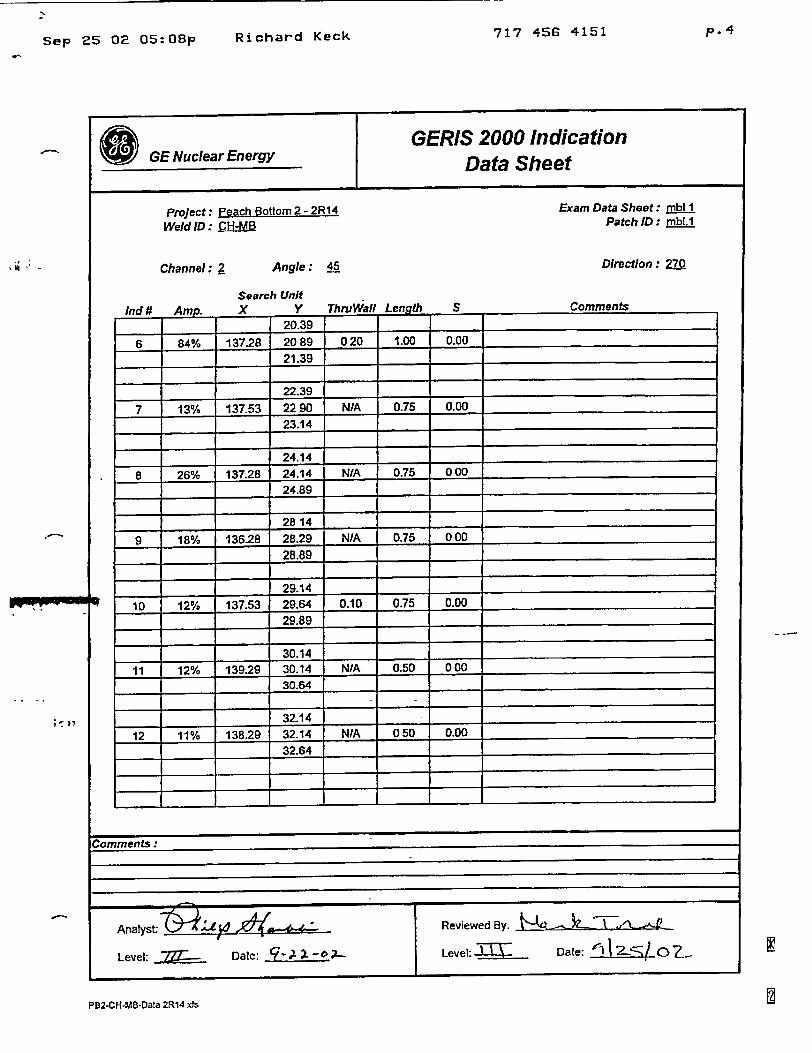
Exam Data Sheet: mbl I Patch ID: mbl.1
Direction : 270
CommentsMIu it 11111. ________ .
20.39
6 84% 137.28 2089 020 1.00 0.00
21.39
22.39 ..
7 13% 137.53 2290 N/A 0.75 0100
23.14
24.14
8 26% 137.28 24.14 NIA 0.75 000
24.89
2814
9 18% 136-28 28.29 N/A 0.75 000
28.89
29.14 10 12% 137.53 29.64 0.10 0.75 0.00 ..
29.89 ._
30.14
11 12% 139.29 30.14 N/A 0.50 000
30.64 ..
32.14
12 11% 138.29 32.14 NIA 050 0.00 ..
32.64
Comments:
PB2-CH-MB-Data 2R14 xAs
Angle: 45
Search Unit
Analyst -0 .• X -"... -- Reviewed By.- . 0 3 L. t-!'L ._
Level: Date: 9-.1 1 o' Level: L Date: I 1~ o.
S

PB2-CH-MB-Data 2R14 xAs
GERIS 2000 Indication Data Sheet
Project: Peach Bottom 2-2R14 Weld ID: CH-MB
Channel: 2
Exam Data Sheet: rnbU. Patch ID: mbl.1
Direcion : 27MAngle : 45
Ind 0 Am.
13 17%
14 24%
--15 __14'%/
16 76%
-- 17 13%
18 34%
19 187%A
Search Unit X Y Len
3489
13603 35.14 N/A 0.75 3564
36.64
136.53 37.64 0.16 1.75 3839
40.14
137.78 40.64 NIA 0.75 4089
41.64 137.28 44.4 0.25 3.75
45.39
4-5.14 133 03 45.39 NIA 0.75
45 89
t48.14 137.53 48.39 NIA 0.75
48.89
50.64 137.78 52.14 N/A 2.50
53.14
Level: • Date. c-,l -
Reviewed By:
Level: _ - Date; "'1.1-2 0 '-"
PB2.CH-MB-Data 2R14 xis
S
0.00
0.00
0.00
0.00
0.00
0O00
0
Comments

717 456 4151Sep 25 02 05:08p
GERIS 2000 Indication Data Sheet
Project: Peach Bottom 2- 2R14 Weld ID : C B
Channel: 2 Angle : 45
Search Unit X y ThruWall Len 117
52.39
135.78 53.39 0.17 1 25 5364
55.14
137.28 56.14 N/A 1.50
- N56 64
55.14 135.78 55.30 N/A 0.50
55.64
57.89
13553 58.39 N/A 1.00 58.89
58.39
13707 58.89 017 1.00 5939
58.89
137.28 60.14 NA 1.75 6064
S
0. 007
000i
0.00
Ind # ArT .
20 22
21 31
22 17%
23 31%
24 41%
Reviewed By:
Level: I_%_%,__ Date:-~ 2 oZ
pBz-CH-MS-Data 2R14 x13
Exam Data Sheet: mbt I Patch ID: mb:
Direction : M
Comments
p. 5
0.00
Goo I
I
Richard Keck

Sep 25 02 05:O9p Richard Keck 717 456 4151 P. 9
E GERIS 2000 Indication SGE Nuclear Energy Data Sheet
Project: Peach Bottom 2 - 2R14
Weld ID: CH-MB
Channel: 2 Angle : 45
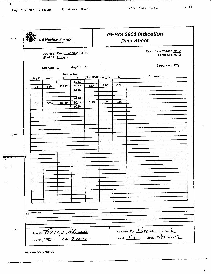
Exam Data Sheet: mbl2 Patch ID : mbl 2
Direction : 270
Ind# AeSearch Unit X Y ThruWaf1 Length S Comments
1 63.64
28 20%1O 137.78 63.89 NIA 0.25 00
63.89
67.89
27 12% 139.04 68.39 N/A 0.75 000 6864
73.14
28 15% 138.04 73.39 N/A 0.75 000
73.89
74.89
29 76% 138 04 75.14 N/A 0.75 0.00
7564
76.89
30 143% 138.04 77.39 NIA 1.25 0.00
78.14
82.64
31 91% 138.54 83.14 N/A 2.25 0.00 84.89
87.14
32 156% 138.79 87.89 NIA 1 00 0.00
88.14
PB2-CH-MB-D2t2 2R14 xkr
Analyst."L , , Reviewed By:
Level. . Date: ¼' 2- Level: I Date: "1 -
ommonts.:
.0
0, mi rl
7- - -- K
717 456 4151Sep 25 02 05:09p
GERIS 2000 Indication Data Sheet
Project: Peach Bottom 2- 2R14 Weld ID; CH-MB
Channel: 2 Angle: 45
Search Unit X V Thru Wa II Length_
8989 139.29 90.14 NIA 2.05
91.94
91.89
139.0 92.14 0.16 0.75
Reviewed By: ý- _ •-, •e•
Level: -_ _U - D .te. --J__ _ - !
PB2-CH-MB-Oata 2R14 xAs
Exam Data Sheet: mbl 2 Patch ID : mb__2
Direction : 27.0
Comments
0.00
0.00
p. 10
vInd # Amp.
33 64%
34 53%
S
I i
Richard Keck

717 456 4151 p. 1 1
Sep 25 02 05:09pd
GENuclearEnergy GERIS 2000 Indication Data Sheet
Project: Peach Bottom 2 - 2R14 Weld lD: CH-MB
Channel: 2 Angle: 45
Exam Data Sheet: Patch ID : mbt.4
Direction : 270
Search Unit IndU m x Y ThruWafl Lenoth S Comments
5.39
35 18% 137.03 564 N/A 0.50 000
5 89
Comments"
PB2-CH-M B-Data 2R14 xts
Analyst: R at -r%-- Levtewed By: te • '
Level 77~Z--.. Date: '~-!F-- Level: ----- Date: 'I e~RI -
Richard Keck
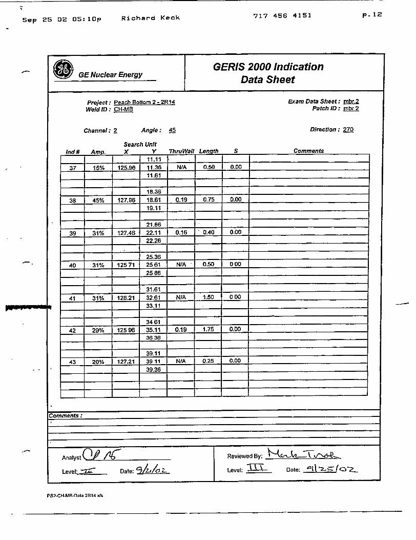
Sep 25 02 05:lOp Richard Keck 717 456 4151 p. 1 2
GERIS 2000 Indication Data Sheet
Project: Peach Bottom 2 - 2R1 4 Weld ID: CH-MB
Channel: 2 Angle: 45
Search Unitl� A,,.ri V V ThniWnII Leneith S
Exam Data Sheet: mbr.2 Patch ID: mbr2
Direction : 270
Comments_______ ~~~~11.11 ____ ____ _____________________
37 15% 125.90 11.36 N/A 0.50 0.00
11.61
18.36
38 45% 127.96 18.61 0.19 0.75 D.00 19.11
21.86
39 31% 127.46 22.11 0.16 0.40 0.00
22.26
25.36
40 31% 12571 2561 NIA 0.50 000
2586
31.61
41 31% 126.21 32.61 N/A 1.50 000
33.11
3461
42 29% 12596 35.11 0.19 1.75 0.00 3636
39.11
43 20% 127.21 39 11 N/A 0.25 0.00
39.36
PB7-CH-MR-1)ata 2R14 xs

717 456 4151Sep 25 02 05:08p
GERIS 2000 Indication Data Sheet
Project: Peach Bottom 2--2B14 Weld ID: :-MB
Channel: 2 Angle: 45
Search Unit X Y ThruWall Len th
40.36
45% T128.22 40.61 0.17 075 41.11
41.36
414 128.22 41.86 NIA 1.00 42.36
4286
20% 128.47 42.86 N/A 0.50 43.36
45.86
34% 28.22 46.11 NIA 0.75 4661
Reviewed By:
Level: A Date: 5 ! 7 .-- ci..
PB2-CH-MB-Datm 2R14 A5
Exam Data Sheet: mbr.2 Patch ID: mbr.2
Direction: 27.0
Ind #
44
45
46
47
Comments
p.6
S
0.o0__
0.00
0.00
0.00
Richard Keck
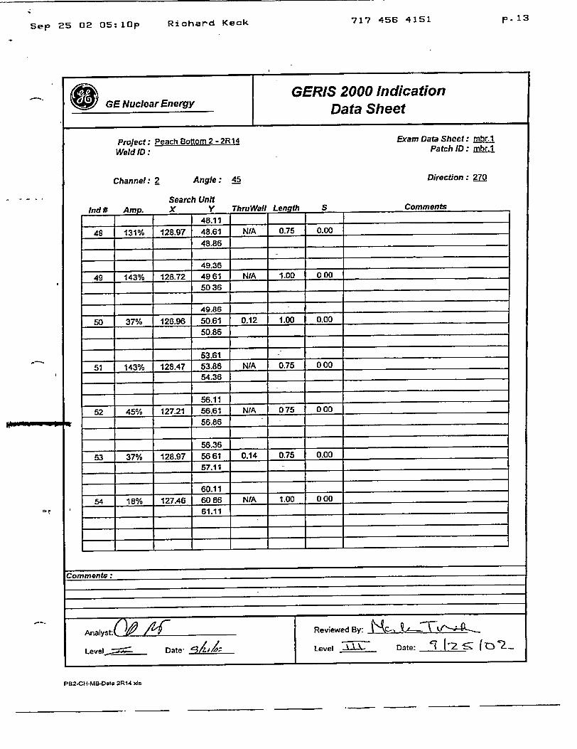
Sep 25 02 05:1Op Richard Keck717 456 4151 p. 1 3
Project: Peach Bottom 2 - 2R14 Weld ID :
Channel: 2 Angle: 45
Search Unit l-JJ A..... V Thri WA•l len
S
Exam Data Sheet: mbr.1 Patch ID : mbr.1
Direction : 27M
Commentsl48.11 9w Am.__81
48 131% 128.97 48.61 N/A 0.75 0.00
48.86
49.36
49 143% 128.72 4961 N/A 1.00 000
5036
49.86
50 37% 126.96 50.61 0.12 1.00 0,00
50.86
53.61 51 143% 128.47 53.86 N/A 0.75 0 00
54.36
56.11
52 45% 127.21 56.61 NIA 075 000
56.86
56.36
63 37% 128.97 5661 0.14 0.75 0.00
57.11
60.11
54 18% 127.46 6086 N/A 1.00 000
61.11
L• O nlrr/nLb•
P82-CH-MB-Data 2R14 x~s
Analyst;ov 1 - Reviewed By: ,
Level.~ Date- 13A Level .AL~ Date: '-(z o2.
GENularEeryGERIS 2000 Indication GE Ncler EnrgyData Sheet
Commenwf=

717 456 4151Sep 27 02 11:31a
Project: Peach Bottom 2 - 2R14 Weld ID: CH-MB
Channel: g Angle: 45
Search Unit n--JJ%, V T'hr,,WdI nnl t S
Exam Data Sheet: mbr.1 Patch ID: mbr.1
Direction: 270
Comments
61.10
55 22% 129.47 61.36 NIA 0.51 0.00
61.61
72.61
56 100%'/ 129.71 73.10 0.17 1.00 000
73.61
74.61
57 109% 129.47 75.11 0.17 1.00 000
75.61
80.11
58 70% 129.22 80.61 N/A 1.25 0.00
81.36
81.61
59 45% 129.72 82.11 N/A 0.75 0.00
82.36
8411
60 45% 12947 84.11 NIA 0.50 0.00
84.61
84.61
61 171% 128.97 85.11 0.12 1.00 000
85.61
Comments: None
Analyst: R By:eved By: t' 1 "-14
Level: -7 Date, Level. _ Date: Cl l
PB2-CH-MO-Data 2R14 xis PEACH BOTTOM z R 1. .
PAGE .J.Q..O F - .OF ....._
GENcerEeg GERIS 2000 Indication GE Ncler EnrgyData Sheet
p.3Richard Keck
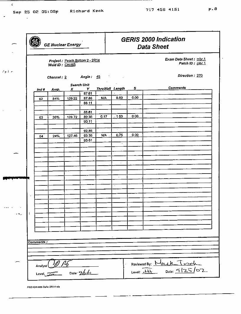
Sep 25 02 05:0Spp.8
Richard Keck 717 456 4151
E GERIS 2000 Indication GE Nuclear Energy Data Sheet
Project: Peach gottom 2- 2R14 Weld ID: :IM8
Channel: 2 Angle: 45
Search Unit • •.,•, 'p
�*j4ffJ U ,.*hm- I h CCm et Mna .4 . A ."! y
Exam Data Sheet: mbr.1 Patch ID: mbr I
Direction : 270
Comments
0 . I ,,,9U
62 84% 129.22 87.86 N/A 0.50 0.00
88.11
88.61 63 26% 128.72 8936 0.17 -150 000
90.11
_9286
64 24% 127.46 9336 NWA 0.75 000
9361
I I I I I
I _ _ _ _ I - I-__ - I i II____ I ______ I ____II___I
Comments:
Level.-,,a Date- ___k__k__ Level: " Date: 'I 1-2'"-- /11Y2-
PB2-CH-MB-Data 2R14 As

Sep 25 02 05:10p
SGE Nuclear Energy GERIS 2000 Indication
Data Sheet
Proaint- Pe~ne~h Rnltnrm 9..9•14 - .... ..
,CO
ru Wall Lenath
,xam vata Sheet: nbr.1 Patch ID: mbr.1
Direction : 270
127.51 65 26% 12802 9225 NIA 1.00 000
128 52
'mments:
PB-CH-M B-Data 2R14 AiS
2 -Analysta_2R_4 _ _s Reviewed By:
Leel ~Date. ______Level: Date. II2 ~
717 456 4151
Weld ID: CH-MB
Channel: 4 Angle: 45
Search Unit Ind # Am. X Y ThA
p. 14Richard Keck

GENE 0000-0007-9747, Rev. I
APPENDIX B
GERIS 2000 Indication Evaluation Data Sheets
Rev 1 September 2002
(Includes 2 New Pages September 27, 2002)
B
I-
717 456 4151 p.15Sep 25 02 05:lOp
1*
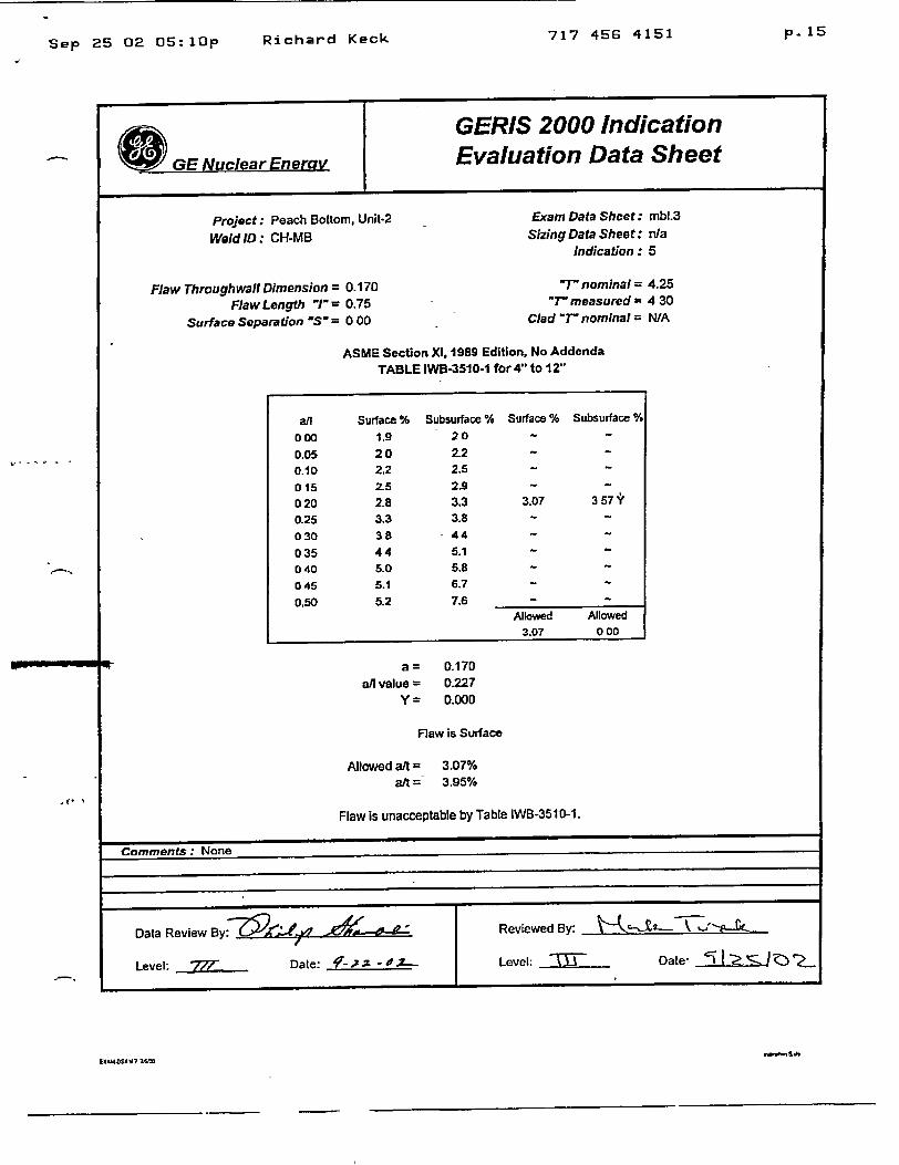
(aGE Nuclear Enerav
GERIS 2000 Indication Evaluation Data Sheet
Project: Peach Bottom, Unit-2
Weld ID: CH-MB
Flaw Throughwall Dimension= 0-170 Flaw Length "1/= 0.75
Surface Separation 'S" = 0 00
Exam Data Sheet: mbl.3 Sizing Data Sheet: nla
Indication: 5
7r nominal = 4.25 "T" measured 4 30
Clad '"Tnominal N/A
ASME Section XI, 1989 Edition, No Addenda TABLE IWB-3510-1 for 4" to 12"
all Surface % Subsurface % 000 1.9 20
0.05 20 2.2
0.10 2.2 2.5
015 2-5 2.9
020 2.8 3.3
0.25 3.3 3.8
030 38 - 44
035 44 5.1
040 5.0 5.8 045 5.1 6.7
0.50 5.2 7.6
a/l value = y=
Surface % Subsurface %
3.07 3 57''
Allowed Allowed
3.07 000
0.170 0.227 0.000
Flaw is Surface
Allowed alt = 3.07% at = 3.95%
Flaw is unacceptable by Table IWB-3510-1.
Comments: None
EIXMOSAV7 76tO
Data Review By:' ?'.j4 / ',.-L-d-" Reviewed By:
Level: • Date: f.,,..Z , -0Z... Level: "7'- Date-
I
Richard Keck
717 456 4151 p.111Sep 25 02 05:10p
GERIS 2000 Indication
GE Nuclear Eneray Evaluation Data Sheet
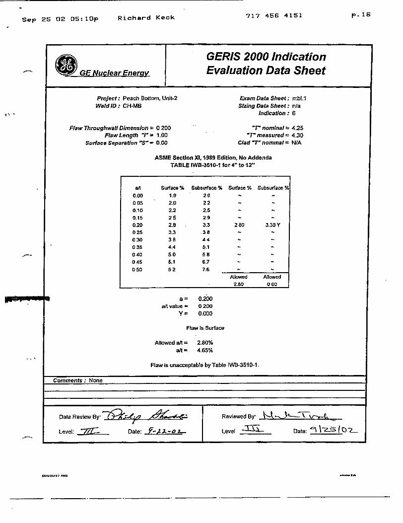
Project: Peach Bottom, Unit-2 Weld ID: CH-MB
Flaw Throughwall Dimension = 0 200 Flaw Length "I"= 1.00
Surface Separation "S' - 0.00
Exam Data Sheet; mbl.1 Sizing Data Sheet: n/a
Indication: 6
"T" nominal = 4.25 "T" measured= 4.30
Clad " nominal= NIA
ASME Section Xl, 1989 Edition, No Addenda TABLE IWB-3510-1 for 4" to 12"
al= a/1 value
Y=
0.200 0200 0.000
Flaw is Surface
Allowed aft = 2.80% alt = 4.65%
Flaw is unacceptable by Table IWB-351 0-1.
Comments: None
LXWO,4 V 7 7SIM
a/[ Surface % Subsurface % Surface % Subsurface %
0.00 1.9 20 -
005 2.0 22 -
0.10 2.2 2.5 -
0.15 25 29 -
0.20 2.8 3.3 280 3.30 Y
025 3.3 38 -
030 38 44 -
035 4.4 5.1 -
040 50 58 -
045 5.1 6.7 -
050 52 7.6 -
Allowed Allowed 2.80 000
Data Review By"La 49iO A-,,,.,- Reviewed By
I
Level: . Date: 9F-2.L-OA L. Level ________ Date: '~
Richard Keck
-a-d

Sep 25 02 05:11pp. 1 7
Richard Keck 717 456 4151
S GE Nuclear Enemy
GERIS 2000 Indication Evaluation Data Sheet
_______________________________________________ .1 _________________________________________________________________________________
Project: Peach Bottom, Unit-2 Weld ID: CH-MB
Flaw Throughwall Dimension = 0.160 "FlawLength l'1 1.75
Surface Separation "S' - 0.00
Exam Data Sheet: mbl.1 Sizing Data Sheet: n/a
Indication: 14
"T" nominal = 4.25
"T" measured = 4.30
Clad "T- nominal = NIA
ASME Section XI, 1989 Edition, No Addenda TABLE iWB-351 0-1 for 4" to 12"
a = 0.160 a/l value - 0091
Y = 0.000
Flaw is Surface
Allowed alt = 2.17%
at = 3.72%
Flaw is unacceptable by Table IWB-3510-1.
Comments: None.
Data Review By Reviewed By: Date: '
Level: -2..Z7--.. Date: 7-22Level. ~ ~~ Date: 917 r-> Z...
,- 4
1XAWS4 'V7 7.W
717 456 4151 p.18Sep 25 02 05:11p
_______________________________________ Y
0 GE Nuclear Energy_____________________________________ I
GERIS 2000 Indication Evaluation Data Sheet
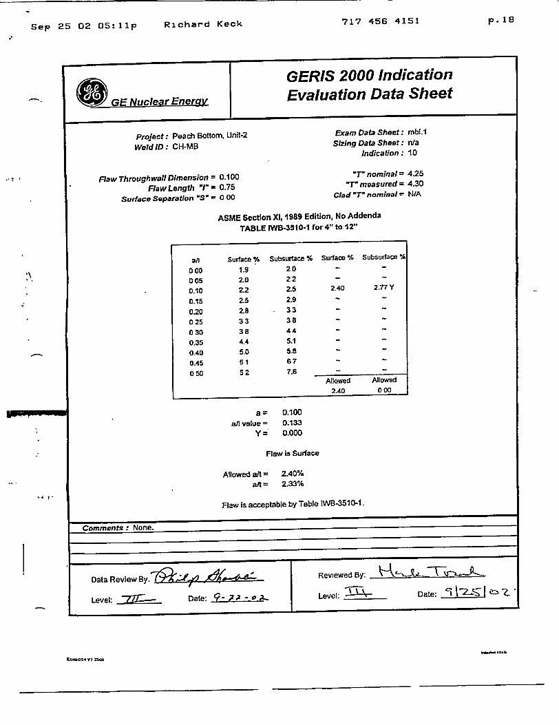
Project: Peach Bottom, Unit-2 Weld ID: CH-MB
Flaw Throughwall Dimension = 0.100 Flaw Length "I = 0.75
Surface Separation "S" - 0 00
Exam Data Sheet: mbl.1 Sizing Data Sheet: n/a
Indication : 10
"T- nominal = 4.25 "T" measured = 4.30
Clad "T" nominal - N/A
ASME Section XI, 1989 Edition, No Addenda TABLE IWB-3510-1 for 4" to 12"
a/l 000 005 0.10 0.15
0.20
Surface % 1.9 2.0 2.2
2.5
2.8
Subsurface % Surface % Subsurface %
20 22 2.5
2.9
33
2.40 2.77 Y
025 33 38 -
030 38 44 -
0.35 4.4 5.1 -
0.40 5.0 5.8 -
0.45 51 67
050 52 7.6 -Allowed Allowed
2.40 0c00
a 0.100 a/l value = 0.133
y= 0.000
Flaw is Surface
Allowed a/t = 2A0% ai = 2.33%
Flaw is acceptable by Table IWB-351 0-1.
Comments: None.
ECAM-S4V7? Z5=,
Data Review By. R Date •- , 6 - Reviewed By:
Level: Date: 9 ;? Level: ______ Date: ~ V~
Richard Keck

717 45G 4151 p. 1 9
Sep 25 02 05:11p
GERIS 2000 Indication GE Nuclear Enery Evaluation Data Sheet
Project: Peach Bottom, Unit-2 Exam Data Sheet: mbl.1
Weld ID: CH-MB Sizing Data Sheet: Na Indication: 16
Flaw Throughwali Dimension = 0.250 "T" nominal = 4.25 Flaw Length "J"= 3.75 "" measured = 4.30
Surface Separation S' = 0.00 Clad -T" nominal= NIA
ASME Section Xl, 1989 Edition, No Addenda TABLE IWB-35t0-1 for4" to 12"
a/l Surface % Subsurface % Surface % Subsurface %
0.00 1.9 2.0 -
0.05 2.0 2.2 2.07 2.30 Y
0.10 2.2 2.5 -
0.15 2.5 29 -
020 2.8 33 -
025 3.3 38 -
0.30 3.8 4.4 -
035 44 51 -
0.40 50 5.8 -
0.45 5.1 6.7 -
050 5.2 7.6 -
Allowed Allowed
207 000
a = 0250 a/I value = 0.067
Y = 0.000
Flaw is Surface
Allowed aft = 2.07%
aft= 5.81%
Flaw is unacceptable by Table IWB-351 0-1.
Comments: None.
Data Review By:"77T Date: '.-, Reviewed By:- 4te x -
Level: - 7 Date: V?-.x -0 A-- Level: Date: cI -2J-%Z cýZ_
3� e*
Richard Keck
IMIIN4ff• I •L•IEXAU-DSG4V.7 7,•o
717 456 4151Sep 25 02 05:11p
GERIS 2000 Indication Evaluation Data Sheet
GE Nuclear Enerv_
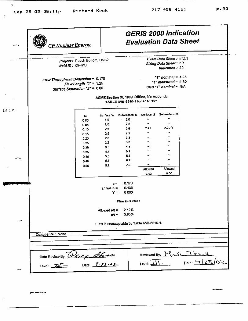
Project: Peach Bottom, Unit-2
Weld ID : CH-MB
Flaw Throughwall Dimension = 0.170
FlawLength "1" = 1.25
Surface Separation "S"- 0.00
ASME Section XI, 1989 Edition, No Addenda TABLE IWB-3510-t for 4" to 12"
a/1 value =
y=
0.170 0.136 0000
Flaw Is Surface
Allowed a/t = 2.42% att - 3.95%
Flaw is unacceptable by Table IWB-3510-1.
Comments: None.
Data Review By:• •- /'- , Reviewed By: • ,£ V---_
Level: _.• --- Date. P',2 o,--Level: Date:
p. 20Richard Keck
Exam Data Sheet: mbl.1
Sizing Data Sheet: n/a
Indication: 20
"T" nominal - 4.25
"T- measured 4.30
Clad T" nominal = N/A

Sep 25 02 05:11pp.l21
Richard Keck 717 456 4151
GERIS 2000 Indication
GE Nuclear Energy Evaluation Data Sheet
Project: Peach Bottom, Unit-2 - Exam Data Sheet: mbl.1
Weld ID: CH-MB Sizing Data Sheet: n/a Indication : 24
Flaw Throughwall Dimension = 0.170 "T" nominal = 4 25
Flaw Length "1'= 1.00 "T" measured = 4.30
Surface Separation "S" = 0.00 Clad "" nominal = N/A
ASME Section XI, 1989 Edition, No Addenda TABLE WVB-3510-1 for 4" to 12"
al a/n value=
y=
0.170 0.170 0.000
Flaw is Surface
Allowed aft = a/t
2.62% 3.95%
Flaw is unacceptable by Table IWB-3510-1.
Comments: None.
al Surface % Subsurface % Surface % Subsurface %
000 19 2.0 -
005 20 2.2 - ~
0.10 2.2 2.5 -
015 25 2.9 262 3 06 Y
0.20 2.8 3.3 -
025 33 38 -
030 38 4.4 -
035 44 5.1 -
040 50 5.8 -
045 5.1 6.7 -
050 52 7.6 -Allowed Allowed
2.62 000
Data Review By: ',.,.,_. ,..-- Reviewed By. ., ,, '
Level: • Date. ?- ;t --.... Level: - Date: '1. a'L(Z

717 456 4151 p.22Sep 25 02 05:1 2 p
GERIS 2000 Indication
GE Nuclear Energy Evaluation Data Sheet
Project: Peach Bottom, Unit-2 Exam Data Sheet: mbL.2 Weld ID: CH-MB Sizing Data Sheet: n/a
Indication: 34
Flaw Throughwall Dimension = 0.160 "T" nominal = 4.25 FlawLength '1"- 0.75 "T measured = 4.30
Surface Separation "S" = 0.00 Clad "Tnominal = NIA
ASME Section Xl, 1989 Edition, No Addenda TABLE IWB-3510-1 for 4" to 12"
a
a/l value =
Y=
,0.160 0.213 0.000
Flaw is Surface
Allowed a/t a24
2.93% 3.72%
Flaw is unacceptabte by Table IWB-3510-1.
Comments: None.
Data Review By Reviewed By.
Level: -.. 2--- Date: 7-~. '-- Level._____ Date: i-ŽO ?
all Surface % Subsurface % Surface % Subsurface %
0.00 19 20 -
0.05 2.0 2.2 -
010 22 25 -
0.15 2.5 2.9 -
020 2.8 33 2.93 343Y
025 3.3 3.8 -
030 3.8 44 -
035 4.4 5.1 -
0.40 5.0 5.8 -
0.45 5.1 6.7 -
0.50 52 7.6 -
Allowed Allowed 293 000
. . p
- -yO4V 75=
Rzchard Keck

717 456 4151 p. 2 3
Sep 25 02 05:12 p
_ _ _ _ GERIS 2000 Indication
GE Nuclear Energy Evaluation Data Sheet
Project: Peach Bottom, Unit-2 Weld ID : CH-MB
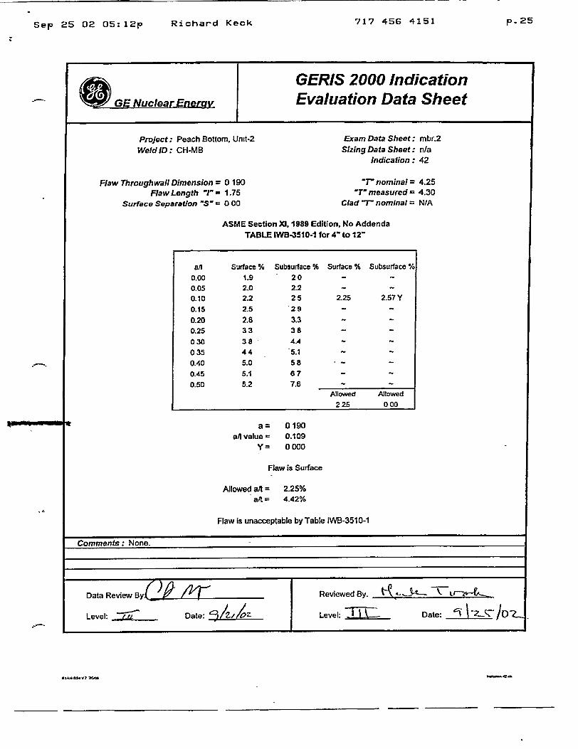
Flaw Throughwall Dimension = 0.190 Flaw Length "I"= 0 75
Surfaco Saparation 'S" = 0 00
Exam Data Sheet: mbr.2 Sizing Data Sheet: n/a
Indication : 38
"T" nominal = 4.25 "T-measured= 4.30
Clad " nominal = N/A
ASME Section X1, 1989 Edition, No Addenda TABLE IWB-3510-1 for 4- to 12"
Wy- ale a/A value=
Y=
0190 0253 0.000
Flaw is Surface
Allowed a/t = 3.33% aM = 442%
Flaw is unacceptable by Table IWB-3510-1.
Comments: None.
T-AOS4 W~ 7 7-
afl Surface % Subsurface % Surface % Subsurface %
000 1.9 2.0 -
0.05 2.0 2.2 -
0.10 2.2 2.5 -
015 25 29 -
0.20 2.8 33 -
025 3.3 38 333 384Y
030 38 44 -
035 44 51 -
0.40 50 58 -
0.45 5.1 6.7 -
050 5.2 7.6 -
Mowed Mowed
333 000
Data Review By. dY - Reviewed By: O r-'&-- ' -.
Level Date: '-)/ - Level: • Date: q1.--1cj 'Z
Richard Keck
717 456 4151 p. 2 4
Sep 25 02 O5:12p
GERIS 2000 Indication
GE Nuclear Energy Evaluation Data Sheet
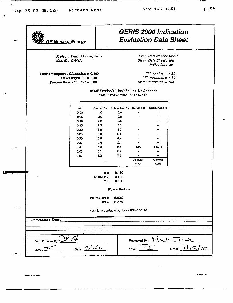
Project: Peach Bottom, Unit-2 Exam Data Sheet: mbr.2
Weld ID: CH-MA Sizing Data Sheet: n/a Indication: 39
Flaw Throughwall Dimension = 0.160 "TO nominal = 4.25 Flaw Length "I'= 0.40 'TO measured= 4.30
Surface Separation "S - 0.00 Clad "T' nominal = N/A
ASME Section X1, 1989 Edition, No Addenda TABLE IWB-3510-1 for4" to 12"
all Surface % Subsurface % Surface % Subsurface %
0.00 1.9 2.0 -
0.05 2.0 2.2 -
0.10 2.2 2.5 -
0.15 2.5 2.9 -
0.20 2.8 33 -
0.25 3.3 38 -
0.30 3.8 4.4 -
0.35 4.4 5.1 -
0.40 5.0 5.8 5.00 580Y 0.45 5.1 6.7 -
0.50 5.2 7.6 -
Allowed Allowed
5.00 000
a= 0.160 a/I value = 0.400
Y = 0.000
Flaw is Surface
Allowed alt = 5.00% aAt = 3.72%
Flaw is acceptable by Table IWB-351 0-1.
Comments: None.
Data Review BT.Y /Al: , Reviewed By: -)A .C
Level-: '"1 Date: ~/' ~Level: 4 L. Date: li s/Y...
€' S.k=,lexAO "V1 7rn
Richard Kock
717 456 4151 p. 2 5
GERIS 2000 Indication
GE Nuclear Energy Evaluation Data Sheet
Project: Peach Bottom, Unit-2 Exam Data Sheet: mbr.2
Weld ID: CH-MB Sizing Data Sheet: nla Indication: 42
Flaw Throughwafl Dimension = 0 190 "T nominal = 4.25
FlawLength "/"= 1.75 "T-measured= 4.30
Surface Separation "S" 0 000 Clad T nominal = N/A
ASME Section XI, 1989 Edition, No Addenda
TABLE IWB-3510-1 for 4" to 12"
an Surface % Subsurface % Surface % Subsurface %
0.00 1.9 20 - ~
0.05 2.0 2.2 -
0.10 2.2 25 2.25 2.57 Y
0.15 2.5 '29 -
0.20 2.8 3.3 -
0.25 33 38 -
030 38 4.4 -A
035 44 5.1 -
0.40 5.0 58 -
0.45 5.1 67 - ~
0.50 5.2 7.6 -
Allowed Allowed
225 000
a -0190 e/A value 0.109
Y= 0000
Flaw is Surface
Allowed aft = 2.25% a/t = 4.42%
Flaw is unacceptable by Table IWB-351 0-1
Comments: None.
Data Review ByCP /'. Reviewed By. t"c,.... -Lr--..
Level: - Date: " Level: • Date: " /
Richard KeckSep 25 02 05:12p

717 456 4151 p. 2 6
I GERIS 2000 Indication GE Nuclear Enery Evaluation Data Sheet
Project: Peach Bottom. Unit-2 Eram Data Shoot: mbr.2
Weld ID: CH-MB Sizing Data Sheet: n/a Indication : 44
Flaw Throughwall Dimension = 0.170 "T' nominal= 4.25
Flaw Length "I'= 0 75 "T" measured = 4.30
Surface Separation "S" = 000 Clad *T" nominal - N/A
ASME Section Xl, 1989 Edition, No Addenda
TABLE IWB-3510-1 for 4" to 12"
all Surface % Subsurface % Surface % Subsurface %
0.00 1.9 2.0 -
005 2.0 2.2 -
010 2.2 2.5 -
0.15 2.5 2.9 -
020 2.8 3.3 307 357Y
025 3.3 3.8 -
030 3.8 44 -
035 44 51 -
0.40 5.0 58 -
045 51 6.7 -
0.50 5,2 7.6 -
Allowed Allowed
307 000
I or a= 0170
ail value = 0.227
Y = 0.000
Flaw is Surface
Allowed alt = 3 07/6 at = 395%
Flaw is unacceptable by Table IWB-3510-1.
Comments: None.
Data ReviewBy(P /ByF" Reviewed By:
Level..D/(OZ Level: J Date: i 5-2_ . .Z. Date: Level:
Sep 25 02 05:12p Richard Keck
U ,mGmlL

717 456 4151 p. 2 7
GERIS 2000 Indication
GE Nuclear Energy Evaluation Data Sheet
Project: Peach Bottom. Unit-2 Weld ID: CH-MB
Flaw Throughwali Dimension = 0 120 Flaw Length 1" = 1.00
Surfaco Separation "S" = 0.00
Exam Data Sheet: mbr.1 Sizing Data Sheet: n/a
Indication: 50
"TI nominal = 425 "T" measured= 4.30
Clad "T- nominal - N/A
ASME Section Xl, 1989 Edition, No Addenda TABLE IWB-3510-1 for 4" to 12"
a = 0.120 aA value= 0.120
Y= 0.000
Flaw is Surface
Allowed a/t = 2.32% /it = 2.79%
Flaw is unacceptable by Table IWB-3510-1.
Comments: None.
Data Review By: O at /P Reviewed By.
Level: ~i7Date: ?f'(rLevel. ______ Dale: 1(2.C/Z.
IJuMOVY ý
a2/ Surface % Subsurface % Surface % Subsurface %
0.00 1.9 2.0 -
0.05 2.0 22 -
0.10 2.2 2.5 2.32 2.66 Y
0.15 2.5 2.9 -
0.20 2.8 3.3 -
0.25 33 3.8 -
0.30 3.8 44 -
0.35 44 5.1 -
0.40 5.0 58 -
0.45 51 67 -
0.50 5.2 7.6 -
Allowed Allowed 232 000
Sep 25 02 05:13p Richard Keck

717 456 4151 p. 2 8
GERIS 2000 Indication GE Nuclear Energv Evaluation Data Sheet
Project: Peach Bottom, UNit-2
Weld ID: CH-MB
Flaw Throughwall Dimension= 0 140 Flaw Length "1" = 0.75
Surface Separation "S" - 0 00
Exam Data Sheet: mbr.1 Sizing Data Sheet: n/a
Indication: 53
"T7 nominal 4 25 "T" measured = 4.30
Clad "T- nominal = N/A
ASME Section X1, 1989 Edition, No Addenda TABLE IWB-3510-1 for 4" to 12"
alu all value=
Y=
0.140 0.187
0.000
Flaw Is Surface
Allowed alt = a/t =
2.72% 3.26%
Flaw is unacceptable by Table IWB-351 0-1.
Comments: None.
(1AJ8547 115
all Surface % Subsurface % Surface % Subsurface % 000 19 20 -
005 2.0 2.2 -
0.10 2.2 2.5 -
0.15 2.5 29 2.72 3.19 Y
020 2.8 33 -
0.25 33 38 -
0.30 3.8 44 -
0.35 4.4 5.1 -
0.40 50 5.8 -
0.45 5.1 67 -
050 52 7.6 -
Allowed Allowed 2.72 000
Data Review By: C / Reviewed By:
Level: -7ae /ell I :D
Richard KeckSep 25 02 05:13p

p. 4Richard Keck 717 456 4151
0 GERIS 2000 Indication GE Nuclear Energy Evaluation Data Sheet
Project: Peach Bottom. Unit-2 Exam Data Sheet: mbr.1 Weld ID: CH-MB Sizing Data Sheet : n/a
Indication : 56
Flaw Throughwall Dimension = 0 170 "T- nominal = 4.25 Flaw Length "/= 1 00 "T measured= 4.30
Surface Separation "S" = 000 Clad '7- nominal = NIA
ASME Section Xi, 1989 Edition, No Addenda
TABLE IWB-3510-1 for A" to 12"
a/I Surface % Subsurface % Surface . Subsurface %
000 19 2.0 - ~
005 2.0 2.2 -
0.10 2.2 2.5 -
0.15 2.5 2.9 2.62 3.06 Y
0.20 2.8 3.3 -
0.25 3.3 3.8 -
0.30 38 4.4 -
0.35 4.4 5.1 -
0.40 50 5.8 -
0.45 51 6.7 -
0.50 52 7.6 -
Aowed Alowed 2.62 000
a 0.170 all value 0.170
Y= 0.000
Flaw is Surface
Allowed aft = 2.62% att = 3.95%
Flaw is unacceptable by Table IWB-3510-1.
Comments: None.
Data Review By - Reviewed By:. t
Level: 7 Date: 9/t zLevel: 3-x-Alý Date:c 1
ffxO".V? ?ýPEArAH .OTT,..
PACE --- -- I)F.. (. _
Sep 27 02 11:31a
• I
717 456 4151Sep 27 02 11:32a
GERIS 2000 Indication
GE Nuclear Eneroy Evaluation Data Sheet
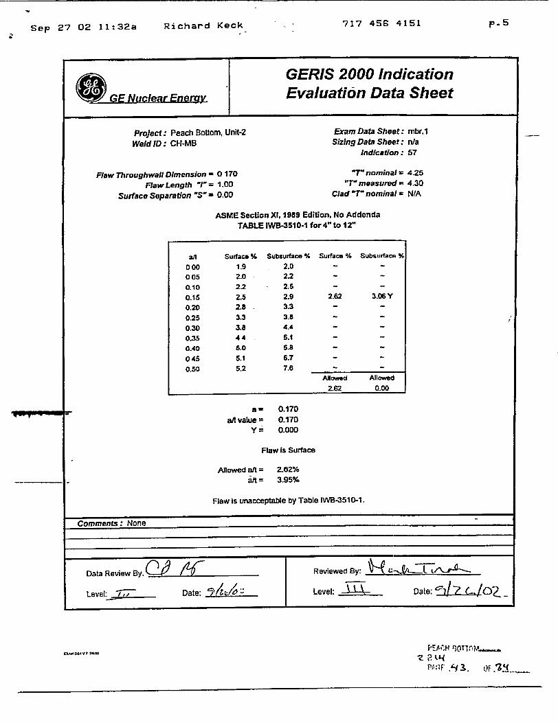
Project: Peach Bottom, Unit-2 Exam Data Sheet: mbr.1
Weld ID: CH-MB Sizing Data Sheet: nia Indication : 57
Flaw Throughwall Dimension 0 170 'T nominal = 4.25
FlawLength '"1= 1.00 " measured - 4.30
Surface Separation "S' 0.00 Clad "r nominal = N/A
ASME Section XA. 1989 Edition, No Addenda TABLE IWB-351 0-1 for 4" to 12"
a/[ Surface % Subsurface % Surface % Subsurface %
000 1.9 2.0 - ~
005 2.0 2.2 -
0.10 2.2 2.5 -
0.15 2.5 2.9 2.62 3.06 Y
0.20 2.8 3.3 -
0.25 3.3 3.8 -
0.30 3.8 4.4 -
0.35 44 5.1 -
0.40 5.0 5.8 -
045 5.1 6.7 -
0.50 5.2 7.6 -
Allowed Allowed
2.62 0.00
a W 0.170 afi value = 0.170
Y = 0.000
Flaw Is Surface
Allowed a/t = 2.02% at = 3.95%
Flaw is unacceptable by Table IWB-351 0-1.
Comments: None
Data Review By. LJ KReviewed By:
Level: Date: i Level: • Date: zcI _
CxC. bUY7 76
±4="F . 3,. 0.:.'i ....
p.5Richard Keck

717 456 4151 p. 2 9
Sep 25 02 05:13p
I GERIS 2000 Indication
GE Nuclear Energy Evaluation Data Sheet
Project : Peach Bottom. Unit-2 Exam Data Weld ID: CH-MB Sizing Data
Indic,
oughwafl Dimension = 0.120 "r non Flaw Length 1 = 1.00 "T" measi
face Separation "S"a 0 00 Clad -T- noir
ASME Section X), 1989 Edition, No Addenda TABLE IWB-3510-1 for 4" to 12"
ae a/l value=
Y=
0.120 0.120 0.000
Flaw is Surface
Allowed a/t = 2.32% a/t= 2.79%
Flaw Is unacceptable by Table IWB-351 0-1.
Comments: None.
Data Review By~ 9 /11T Reviewed By: Tb Q
Level. Date: Level Date.
ta-OS-Vl ly
Flaw Thrn
Su
Sheet : mbr.1 Theet: n/a ation: 61
iinal = 4.25 ured = 4.30 iinal = N/A
all Surface % Subsurface % Surface % Subsurface % 0.00 1.9 20 -
005 2.0 2.2 -
0.10 22 2.5 2.32 2.66 Y 0.15 2.5 29 -
020 2.8 3.3 -
025 3.3 38 -
0.30 38 4.4 -
0.35 44 5.1 -
0.40 50 58 -
045 6.1 6.7 -
0.50 5.2 7.6 -
Allowed Allowed 232 000
I
Richard Keck
717 456 4151 p. 3 0Sep 25 02 05:1 3 p
Q GERI8 2000 Indication GE Nuclear Energy Evaluation Data Sheet
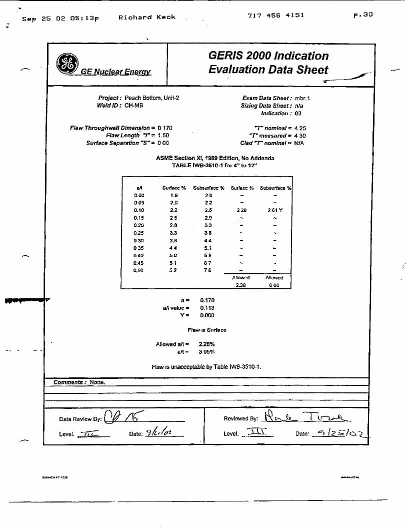
Project: Peach Bottom. Unit-2 Exam Data Sheet: mbr.1 Weld ID: CH-MB Sizing Data Sheet: n/a
Indication: 63
Flaw Throughwall Dimension = 0 170 "T' nominal = 4 25 Flaw Length "T = 1.50 "T" measured = 4 30
Surface Separation "S" = 0 00 Clad "T" nominal = N/A
ASME Section XA, 1989 Edition, No Addenda TABLE IWB-3510.1 for 4" to 12"
a/I Surface % Subsurfave % Surface % Subsurface % 0.00 1.9 20 -
005 2.0 22 -
0.10 2.2 2.5 228 2.61 Y
0.15 25 2.9 -
0.20 2.8 3.3 -
0.25 3.3 35 -
030 3.8 4.4 -
035 44 5.1 -
0.40 5.0 58 -
0.45 51 67 -
0,50 5.2 76 -
Allowed Allowed
2.28 000
a = 0.170 a/l value - 0.113
Y = 0.000
Flaw is Surface
Allowed a/t = 2.28% a/t - 395%
Flaw is unacceptable by Table INB-351 0-1.
Comments: None.
Data Review By: 0 AD : / RevlewedlBy: Dc-J te. lir 2 -- -.
Level. -77e--, Dale: 9/1___/07 Level. _____ Date:*~
FMAflM-UVY MW5
Richard Kock