submerged technologies incorporated
TRANSCRIPT

NOVA SCOTIA COMMUNITY COLLEGE
NOVA SCOTIA, CANADA
SUBMERGED TECHNOLOGIES INCORPORATED
ROV Technical Report
Cory Cauvier CEO Richard Clark CCO
Luke Nicholson Electronic Designer Jonathan Kaye Mechanical Designer
Alex Price R&D Adam Barker Fabrication Brad Smith Destructive Testing
Vince Wilson Fabrication Peter Oster Mentor
5/20/2011

1 NSCC ROV TECHNICAL REPORT
Abstract
Submerged Technologies Incorporated in comprised of engineering technologies students from
the Nova Scotia Community College located in Nova Scotia, Canada. This is the second year our
team has participated in the MATE international ROV competition. We have learned a lot over
the past two years and are excited to demonstrate all of our knowledge and hard work. Last
year we managed to place 12th in the Hawaii competition and we know our craft is much more
capable this year. We have built a very robust vehicle with all of the necessary tools to
accomplish all of the tasks set before us. We are eager to perform our duties and are confident
in our ability to succeed.

2 NSCC ROV TECHNICAL REPORT
Table of Contents
Electronics ..................................................................................................................................................... 4
Program/Controller ................................................................................................................................... 4
Circuit Boards ............................................................................................................................................ 5
Cameras .................................................................................................................................................... 5
Power Distribution .................................................................................................................................... 6
Tether ........................................................................................................................................................ 6
Propulsion ..................................................................................................................................................... 7
Motors and Relays .................................................................................................................................... 7
Motor housings ......................................................................................................................................... 8
Propellers .................................................................................................................................................. 8
Testing Rig ................................................................................................................................................. 9
Vehicle Structure ........................................................................................................................................... 9
ROV Hull .................................................................................................................................................... 9
End Cap Design ....................................................................................................................................... 10
Electronics Housing ................................................................................................................................. 10
Buoyancy ................................................................................................................................................. 10
Task Specific Tooling ................................................................................................................................... 11
Pneumatics .............................................................................................................................................. 11
Task 1: Remove the Damaged Riser Pipe ................................................................................................ 12
Task #2: Cap the Oil Well ........................................................................................................................ 13
Task #3: Collect Water Samples and Measure Depth ............................................................................. 14
Task #4: Collect Biological Samples ........................................................................................................ 15
Troubleshooting Challenge & Learning Experience .................................................................................... 15
Discussion of future improvements ............................................................................................................ 15
Reflections on the experience .................................................................................................................... 16
Acknowledgements ..................................................................................................................................... 16
Appendix A .................................................................................................................................................. 17
Appendix B .................................................................................................................................................. 18
Appendix C .................................................................................................................................................. 19
3 NSCC ROV TECHNICAL REPORT
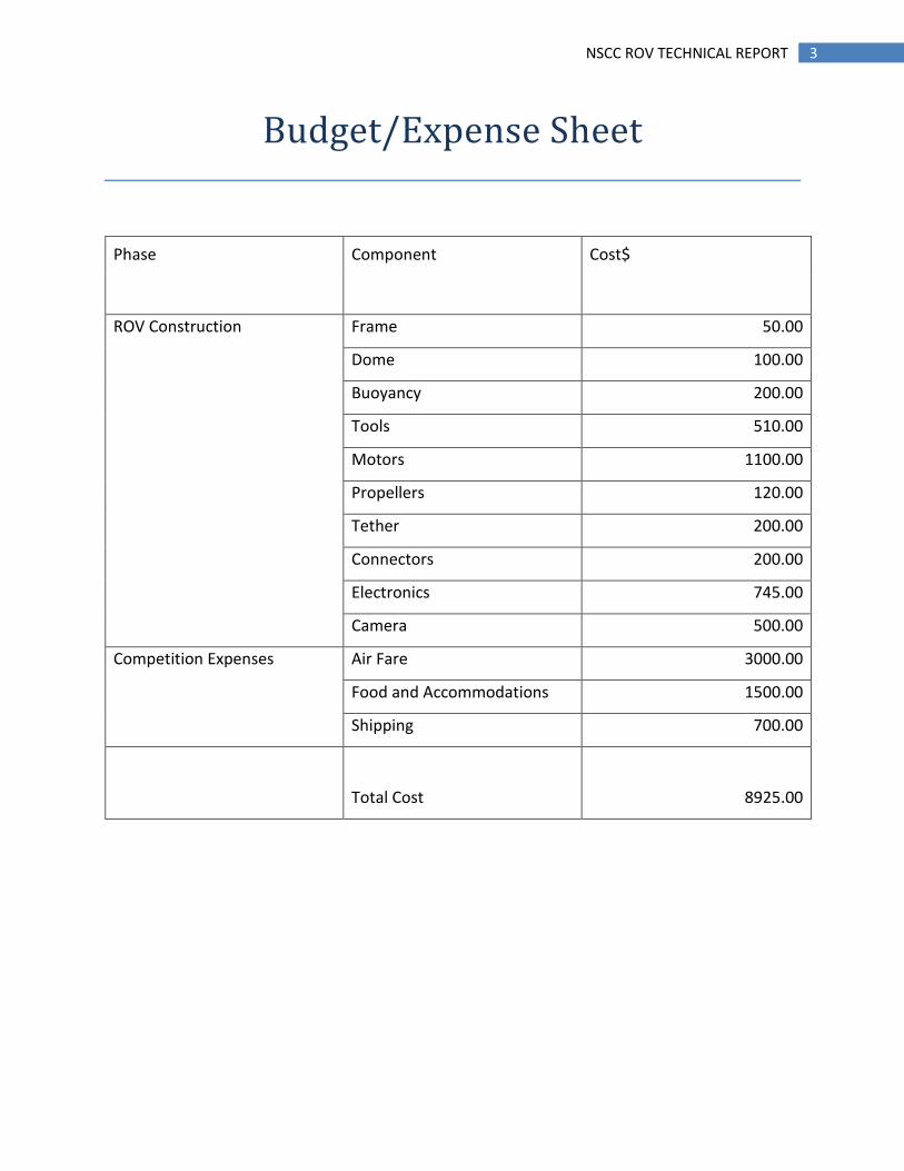
Budget/Expense Sheet
Phase Component Cost$
ROV Construction Frame 50.00
Dome 100.00
Buoyancy 200.00
Tools 510.00
Motors 1100.00
Propellers 120.00
Tether 200.00
Connectors 200.00
Electronics 745.00
Camera 500.00
Competition Expenses Air Fare 3000.00
Food and Accommodations 1500.00
Shipping 700.00
Total Cost 8925.00

4 NSCC ROV TECHNICAL REPORT
Design Rationale
Electronics
Program/Controller
This year we wanted to have a craft that was as user friendly as possible. Last year’s craft used
switches to operate the motors. This design was easy to implement but made it difficult for the
pilot to operate the craft. Due to this we researched and discussed ways to make the controls
as simple as possible. After extensive research we discovered the ease with which an XBOX 360
controller could be used in conjunction with LabView, a graphics based computer programming
software.
With LabView we were able to plug a wired Xbox 360 controller directly into the USB
port of a computer and read the inputs given. We designed a Labview program (Appendix A) to
convert the inputs given from the controller to data that could be easily understood by a micro
controller. Once this was achieved the data was outputted through another USB port. This USB
port was connected to our control box using a UB232. From the control box the data then gets
transmitted through the tether using TTL communication to our onboard microchip
(PIC16F887). To be able to use all the buttons and multiple
directional movements of the XBOX 360 controller, we
constructed two, eight bit strings in Labview where each bit
represented a different controller input. The PIC16F887
(Figure 1) is an 8 bit micro chip and in order to utilize all the
required controls, we had to send two 8 bit strings from Labview. We next had to think of a
way for the PIC to distinguish between the two strings. This was accomplished by making the
most significant bit high on one of the strings and low on the other.
Then we programmed the PIC to read these inputs and act accordingly. Since Labview had
already turned the data into a binary format it was relatively simple to write a C-code that
Figure 1: PIC16F887

5 NSCC ROV TECHNICAL REPORT
would read the 8 bit strings. Since each bit represented a different button or thumb stick
movement on the controller, the C-code had to turn certain ports high and low depending on
the input.
After assembling the final craft our transmission signal was being distorted by electrical
noise. This caused motors and tooling to turn on randomly when other commands were given.
To solve this we had to modify our C-code so that it had to read the same input three times
before it would turn anything on.
Circuit Boards
Last year’s team consisted of solely first year technologists. This
limited our knowledge to basic electronic and electrical systems.
This year’s team now has second year technologists and has helped
the designing of the controls immensely. We were able to design
our own circuits as well as mill our own circuit boards (Figure 2).
This was a huge benefit because the team had all the resources to
complete a circuit from start to finish. We experimented with the milling machine and made
multiple testing boards. At the end of testing we produced three circuit boards; one for our
main circuit board (Appendix B); one circuit board for the relays and pneumatic activation
(Appendix C), and another for our UB232 at the surface. We used these boards for testing our
craft as well as the regional competition. We are outsourcing the main circuit board fabrication
before the competition, to a recognized circuit board manufacturer, to increase reliability.
Cameras
This year we wanted to have one main camera with the
ability to pan and tilt instead of multiple cameras. After
researching various types of cameras, we decided to use an
Ethernet camera (Figure 3). There are various types of
Ethernet cameras on the market so it took a lot of research
Figure 2: Circuit Board
Figure 3: Ethernet Camera

6 NSCC ROV TECHNICAL REPORT
to find a suitable one.
The camera is placed on the front of the craft for navigating, as well as tool observation.
It is controlled by a laptop computer at the surface. A disadvantage of an Ethernet camera is
the price. In order to receive the same amount of frames per second that a USB camera offers
we had to increase our budget for cameras.
Power Distribution
According to the Design and Building Specifications of the competition we are given a 48 volt
source. Since it is required to send all the voltage to the craft our design required us to have
multiple voltage regulators. We used two 12 volt regulators and one 24 volt regulator which
allowed us to distribute various levels of power to all electronic devices. The 24 volt regulator
was used to power four of our six motors. This design allows the motors to draw up to six amps
each. One of the 12 volt regulators is used to power the camera and the main electronics
board. It is capable of powering more electronics, but to reduce electrical noise we decided to
use a separate 12 volt regulator for the remaining two motors. We decided to use a 12 volt
regulator for the remaining two motors because our vertical propellers were designed to
operate at a lower rpm. The specifications of the DC to DC converters state that they will be
operational when they receive a voltage supply over 36 volts. This will allow adequate room for
voltage loss caused by the tether.
Tether
This year the team invested in an industry grade tether. It consisted of four power wires and six
data communications lines. A lesson we learned from last year’s craft is to have a neutrally
buoyant tether that was light weight. This will allow the craft to maintain maneuverability at
long distances. Another major improvement from last year’s craft is the reduction in voltage
losses due to the wire quality. The tether was a very good investment for our team and future
NSCC ROV Teams.
7 NSCC ROV TECHNICAL REPORT
Propulsion
Motors and Relays
To limit the time spent on motor housing design and fabrication we decided to use six identical
motors for all propulsion. Four motors are used for horizontal propulsion and two for vertical
propulsion.
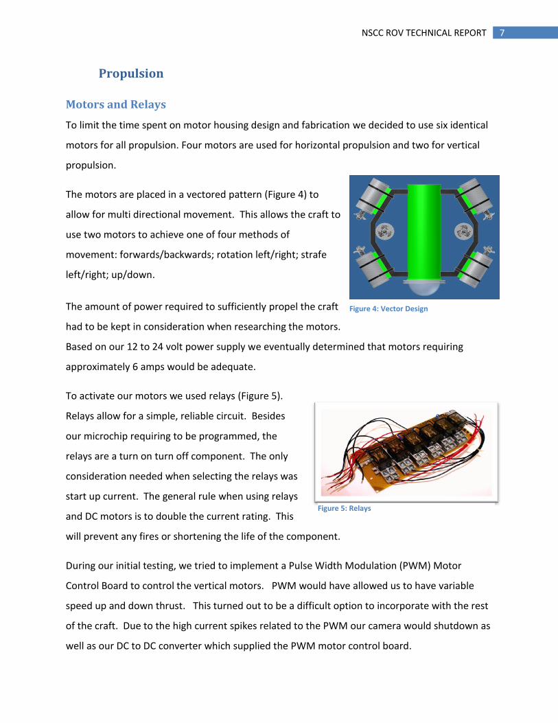
The motors are placed in a vectored pattern (Figure 4) to
allow for multi directional movement. This allows the craft to
use two motors to achieve one of four methods of
movement: forwards/backwards; rotation left/right; strafe
left/right; up/down.
The amount of power required to sufficiently propel the craft
had to be kept in consideration when researching the motors.
Based on our 12 to 24 volt power supply we eventually determined that motors requiring
approximately 6 amps would be adequate.
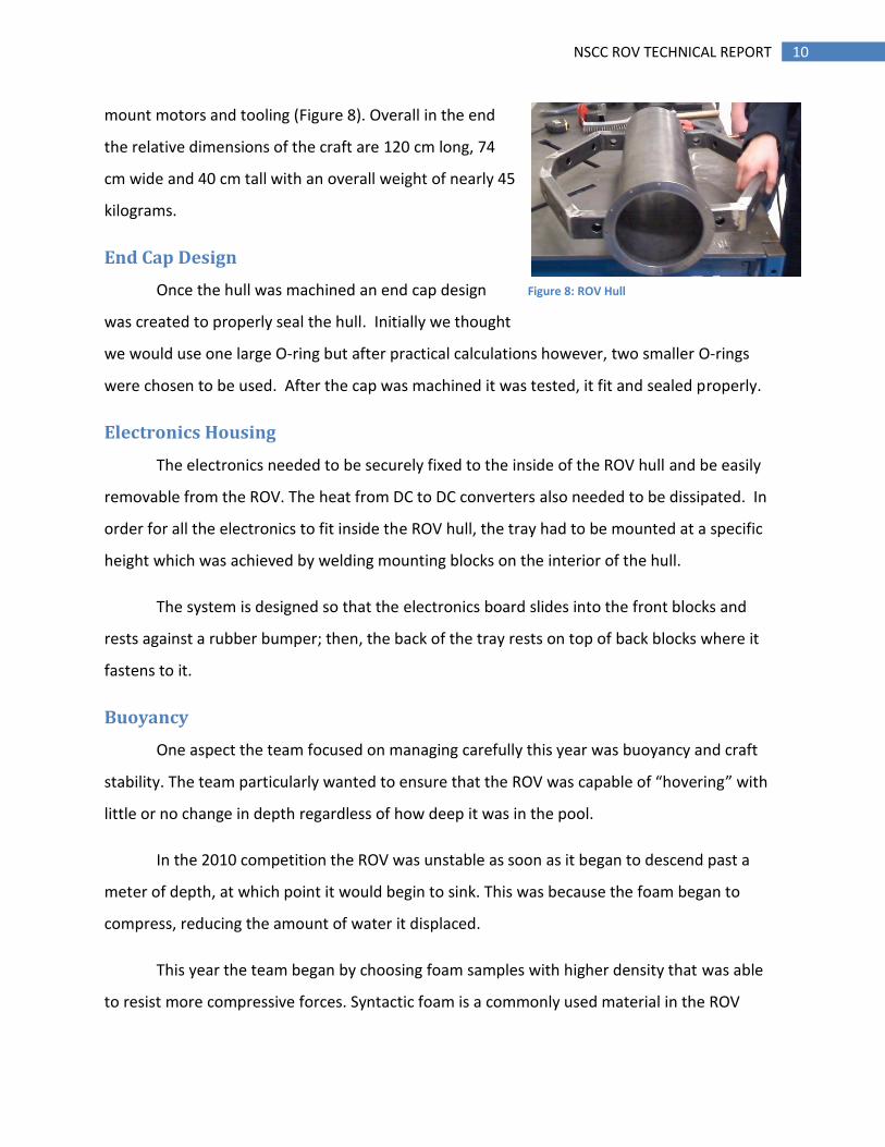
To activate our motors we used relays (Figure 5).
Relays allow for a simple, reliable circuit. Besides
our microchip requiring to be programmed, the
relays are a turn on turn off component. The only
consideration needed when selecting the relays was
start up current. The general rule when using relays
and DC motors is to double the current rating. This
will prevent any fires or shortening the life of the component.
During our initial testing, we tried to implement a Pulse Width Modulation (PWM) Motor
Control Board to control the vertical motors. PWM would have allowed us to have variable
speed up and down thrust. This turned out to be a difficult option to incorporate with the rest
of the craft. Due to the high current spikes related to the PWM our camera would shutdown as
well as our DC to DC converter which supplied the PWM motor control board.
Figure 4: Vector Design
Figure 5: Relays

8 NSCC ROV TECHNICAL REPORT
Motor housings
During the initial conception of our motor housings it was
decided to use metal to attempt to facilitate heat transfer
away from the motors. For this reason the motor housings
(Figure 6) are constructed of aluminum due to its lower
weight and high heat capacity.
It was difficult to ensure that the shaft seal of the motor
housing was water tight. We initially selected O-rings to seal the motor shafts. During testing
we occasionally encountered leaks which we believed were a result of a poor shaft seal. We
attempted different seal configurations and eventually x-rings were selected because they fit in
the existing O-ring glands. The new seals provided lasting results even when encountered with
non-concentric shaft operation. We speculate this is due to the two sealing surfaces in contact,
as well as a small grease pocket that is trapped in the seal during operation providing greater
friction protection.
Another design feature of the motors is a check valve installed in each of the housings. This
allows for a vacuum generator to produce a negative pressure within the housing. This does
two things. First, it is an indication if the motor is still sealed; and second, it pulls the seals into
place much like they would if they were under pressure from depth.
Propellers
This year we decided a key point of our propulsion design would rely on choosing the right
propeller for our motors. At first we began looking at different options
available in our area but found it difficult to find ample selection. We
later were fortunate to have access to a three dimensional printer that
could print objects created with solid modeling computer aided design
software (Figure 7).
At first we were not certain if any propeller printed off would be strong
Figure 6: Motor and Housing
Figure 7: 3D Printer Propellers

9 NSCC ROV TECHNICAL REPORT
enough. After further research we found that there were different treatments that could be
applied to a propeller to increase its rigidity, notably covering it with epoxy.
Initially we began our propeller selection based on our motor power requirements. We
understood that the horizontal motors would be supplied a theoretical constant 24 volts with
approximately 6 amps of current. To attain a propeller that matched this profile we had to
follow an iterative process of testing and design modifications until a final design was achieved.
We also required two motors that could run in both forwards and reverse to move up and
down. For these motors we created a propeller that was more efficient in both directions by
adjusting the pitch of the blades.
Testing Rig
With the 3D printing of propellers of different characteristics and sizes, testing needed to be
done to determine the best propellers to use. Initially we performed tests that did not produce
accurate thrust data but simply indicated a reading relative to the other propellers. The scale
that was used was a spring scale which was inaccurate and the tester itself was unstable.
A new design was created which involved the use of an arm connected to a static digital scale
that would not move which permitted increased accuracy when inspecting the thrust created
by the motors.
Vehicle Structure
ROV Hull
The main hull is where the electronics and camera are housed. A standard 6” SCH 10
steel pipe was chosen for the hull to allow plenty of room inside for the electronics and camera.
A flange was welded onto the front of the hull where an acrylic dome is fastened; the flange
was cut using a CNC plasma cutter and then welded to the front of the pipe. The back of the
ROV hull needed to be machined so there would be a smooth round surface for the o-ring to
mate with. Steel supports were also welded to the side of the main hull to provide locations to
10 NSCC ROV TECHNICAL REPORT
mount motors and tooling (Figure 8). Overall in the end
the relative dimensions of the craft are 120 cm long, 74
cm wide and 40 cm tall with an overall weight of nearly 45
kilograms.
End Cap Design
Once the hull was machined an end cap design
was created to properly seal the hull. Initially we thought
we would use one large O-ring but after practical calculations however, two smaller O-rings
were chosen to be used. After the cap was machined it was tested, it fit and sealed properly.
Electronics Housing
The electronics needed to be securely fixed to the inside of the ROV hull and be easily
removable from the ROV. The heat from DC to DC converters also needed to be dissipated. In
order for all the electronics to fit inside the ROV hull, the tray had to be mounted at a specific
height which was achieved by welding mounting blocks on the interior of the hull.
The system is designed so that the electronics board slides into the front blocks and
rests against a rubber bumper; then, the back of the tray rests on top of back blocks where it
fastens to it.
Buoyancy
One aspect the team focused on managing carefully this year was buoyancy and craft
stability. The team particularly wanted to ensure that the ROV was capable of “hovering” with
little or no change in depth regardless of how deep it was in the pool.
In the 2010 competition the ROV was unstable as soon as it began to descend past a
meter of depth, at which point it would begin to sink. This was because the foam began to
compress, reducing the amount of water it displaced.
This year the team began by choosing foam samples with higher density that was able
to resist more compressive forces. Syntactic foam is a commonly used material in the ROV
Figure 8: ROV Hull
11 NSCC ROV TECHNICAL REPORT
industry; however, the team tried to reduce costs as much as possible and therefore sought out
other alternatives.
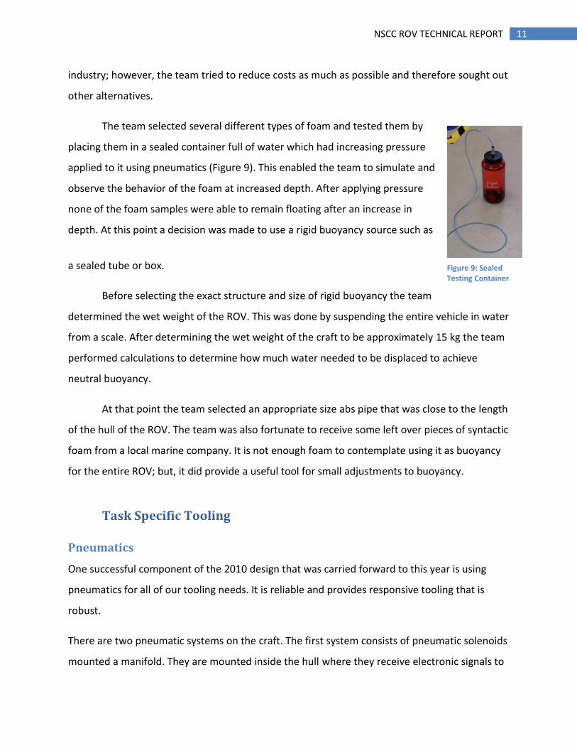
The team selected several different types of foam and tested them by
placing them in a sealed container full of water which had increasing pressure
applied to it using pneumatics (Figure 9). This enabled the team to simulate and
observe the behavior of the foam at increased depth. After applying pressure
none of the foam samples were able to remain floating after an increase in
depth. At this point a decision was made to use a rigid buoyancy source such as
a sealed tube or box.
Before selecting the exact structure and size of rigid buoyancy the team
determined the wet weight of the ROV. This was done by suspending the entire vehicle in water
from a scale. After determining the wet weight of the craft to be approximately 15 kg the team
performed calculations to determine how much water needed to be displaced to achieve
neutral buoyancy.
At that point the team selected an appropriate size abs pipe that was close to the length
of the hull of the ROV. The team was also fortunate to receive some left over pieces of syntactic
foam from a local marine company. It is not enough foam to contemplate using it as buoyancy
for the entire ROV; but, it did provide a useful tool for small adjustments to buoyancy.
Task Specific Tooling
Pneumatics
One successful component of the 2010 design that was carried forward to this year is using
pneumatics for all of our tooling needs. It is reliable and provides responsive tooling that is
robust.
There are two pneumatic systems on the craft. The first system consists of pneumatic solenoids
mounted a manifold. They are mounted inside the hull where they receive electronic signals to
Figure 9: Sealed Testing Container
12 NSCC ROV TECHNICAL REPORT
control them. They are responsible for delivering air pressure to different tooling on the craft.
The system is designed to receive pressure from the surface, and exhaust under water without
any fluid interaction within the internal hull. All pressure is exhausted to the outside water
through redundant check valves. The submerged exhaust eliminates a separate line back to the
surface allowing for a smaller tether.
It is apparent that if there was a leak within the hull, the pressure could be catastrophic. To
combat this there is a check valve in line with the exhaust manifold. If pressure were to leak
into the hull, it would open the check valve and safely vent into the water.
The second pneumatic system is containers attached to the top of the craft. It is connected with
a separate line with a manual control valve located on the surface. The primary purpose of
these containers is to dial in buoyancy and/or assist the vertical motors to elevate more quickly.
Its secondary purpose is to recover the craft in the event of electronic failure rendering the
vertical thrusters ineffective. It is capable of surfacing the craft quickly without putting any
undesired stress on the tether.
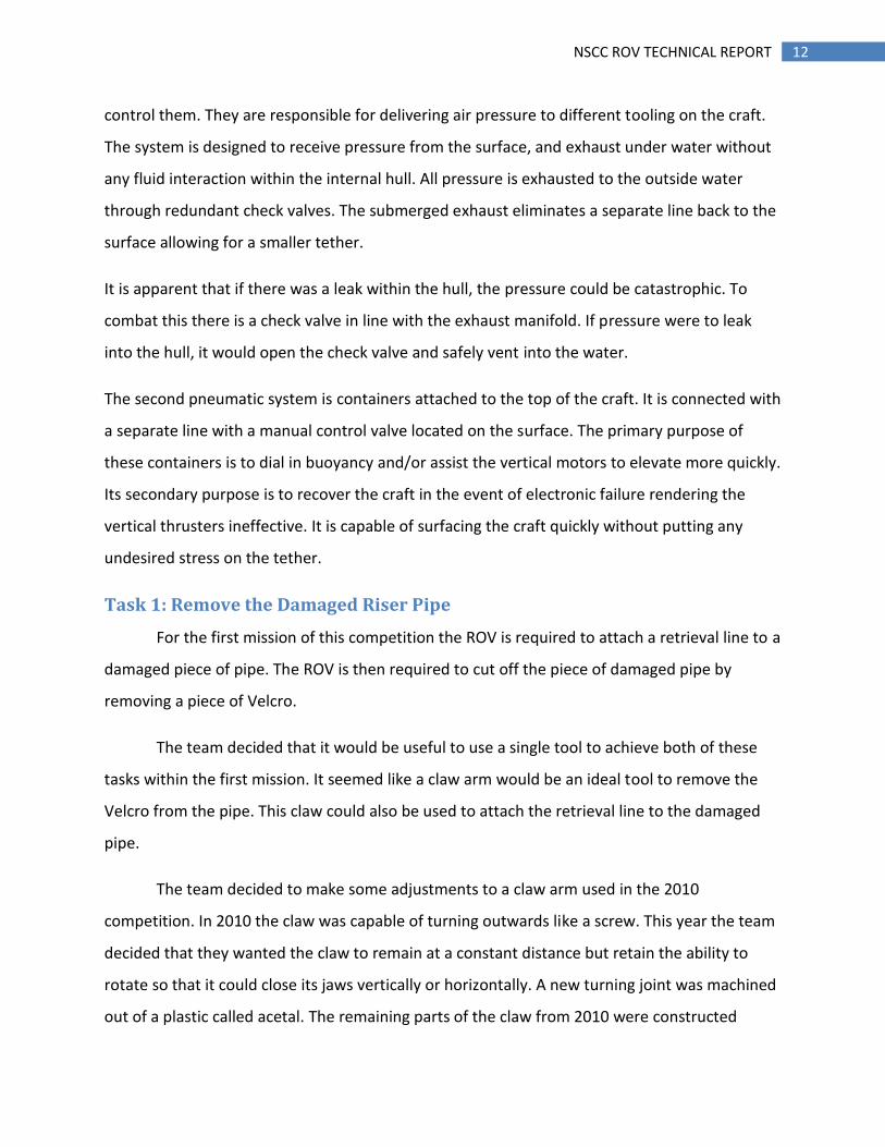
Task 1: Remove the Damaged Riser Pipe
For the first mission of this competition the ROV is required to attach a retrieval line to a
damaged piece of pipe. The ROV is then required to cut off the piece of damaged pipe by
removing a piece of Velcro.
The team decided that it would be useful to use a single tool to achieve both of these
tasks within the first mission. It seemed like a claw arm would be an ideal tool to remove the
Velcro from the pipe. This claw could also be used to attach the retrieval line to the damaged
pipe.
The team decided to make some adjustments to a claw arm used in the 2010
competition. In 2010 the claw was capable of turning outwards like a screw. This year the team
decided that they wanted the claw to remain at a constant distance but retain the ability to
rotate so that it could close its jaws vertically or horizontally. A new turning joint was machined
out of a plastic called acetal. The remaining parts of the claw from 2010 were constructed

13 NSCC ROV TECHNICAL REPORT
primarily from aluminum (Figure 10). All of the
actuators used to rotate and close the jaws of
the claw used pneumatic cylinders.
To maintain simplicity a device similar
to a carabineer would be used to attach the
retrieval line to the damaged piece of pipe. To
enable the claw to hold the carabineer foam
was shaped to fit in the claw jaws and then the
carabineer was fastened to the foam.
Task #2: Cap the Oil Well
During the initial design phases many ideas were circulated on how we could cap the flowing
well. Most spring or mechanical designs provided only one attempt at capping the well. Any
electrically driven designs could never be entirely reliable for they depended too much on
multiple sealing points. It was decided the clamping and capping mechanism be powered by a
pneumatic system due to its robust nature and simple operation. Several linkages were studied
using small diameter rams in which a mechanical advantage could clamp and cap in one
motion. After analyzing build complexity and forces acting on the well head, it was apparent
that nothing could compare to the power and simplicity of utilizing two large diameters rams to
first clamp, and then cap the well with no linkages. The final advantage to utilizing air as a
power source is the ability to disconnect from the well head while enclosed pressure remains
acting in the cylinders.
The pipe capping device is constructed of pneumatic single acting rams, and pneumatic
solenoids, which will be active from the surface once in place over the flowing well head. A first
horizontal ram will close, securing the craft and the clamp in place. Shortly after, a vertical flow
controlled ram will wedge a rubber stopper into the open pipe. Small streamers will indicate
any leaks to the pilots so that they can release the clamp, and readjusting their position if so
desired. Once they are satisfied with the lock and no flow is present, a third pneumatic ram will
Figure 10: Claw

14 NSCC ROV TECHNICAL REPORT
be activated, which releases the pipe capping device from the craft. The pipe capper will remain
fixed in position with pressure still acting on the clamp and the stopper. To recover the pipe
capping device, a simple needle valve has been installed which can be turned by a diver, or the
crafts rotating gripper. Once the needle valve has been cracked, pressure will drain through a
check valve into the water. The single acting rams will return to their resting posting with the
assistance of the built in springs. The cap will then rest free in the water ready for pick up from
either the ROV, or a diver.
Task #3: Collect Water Samples and Measure Depth
The third task of the competition the ROV is required to collect
a sample of water. We decide to base our design loosely on
the concept of a syringe. A piston is actuated in an open
ended cylinder, thus drawing in fluid which is stored in the
body of the cylinder. The fluid is extracted from the container
on the outward stroke and expelled from the ROV on the
return stroke. The pneumatic cylinder must remain under
pressure until the sample is ready to be expelled, or the spring
return will cause the sample to be expelled prematurely.
Our Water Sampler (Figure 11) is mainly constructed of acetel plastic because it is easily
machined, durable and inexpensive to attain.
Clear pneumatic tubing is used to transport the fluid from the container to the syringe piston.
We chose clear pneumatic tubing because it allowed clear visibility of the liquid being extracted
from the container. A spring-returned, pneumatic cylinder is used to actuate the piston of our
water sampler.
To collect depth measurements we are using a divers watch to display depth. This was a simple
solution for our team because one of the team members dives regularly and already had this
cost efficient and accurate depth measurement tool.
Figure 11: Water Sampler
15 NSCC ROV TECHNICAL REPORT
Task #4: Collect Biological Samples
For the biological mission stationary bio samples on the floor of the pool have to be gathered
by the ROV. To accomplish this pneumatic door within a frame attached to a net was designed.
This enabled the door to swing open and then swing closed into the frame, pushing the bio
samples into the net. A net was chosen as opposed to a rigid box to reduce weight and
potential drag as the ROV traveled through the water.
Troubleshooting Challenge & Learning Experience
The electronic members of the team made drastic changes from the control, and
instrumentation of last year’s craft. With the team having a brand new control system, major
bugs had to be ironed out. The first major issue the electronics team faced was the noise factor
do to the increase load caused by the propellers when submersed. This was a major issue due
to the on board microchip requiring a clean signal to decipher the commands from the
controller. We tried using an opto-complier to separate the grounds. This was not successful
due to the slew rate of the chip. We then tried using capacitors to reduce the noise. The
capacitors helped remove part of the noise but the technique that solved the issue was sending
a ground wire from the microchip to the UB232 on the surface. The lesson we learned from
this problem was to have a troubleshooting rationale. Problems can become much more
severe if a plan is not set in place. By discussing the problem you can pin point the issue much
more efficiently. We also learned while troubleshooting it is always good practice not over think
problems, and make assumptions, since it usually ends up being the simple issues like solder
joints and loose connections.
Discussion of future improvements
In the future many components of the ROV could be improved. This year’s craft ended up being
very heavy. One change that could be made in future would be to reduce the size of the motors
and craft simultaneously to reduce overall weight.

16 NSCC ROV TECHNICAL REPORT
Reflections on the experience
Overall our team overcame many difficulties this year to create a very capable machine. We are
all very excited to participate in the competition and continue to learn about the ROV industry
as a whole.
Acknowledgements
We would like to thank our mentor Peter Oster for all his help and guidance with the ROV both
this year and last year. We also owe a great debt of gratitude to all of the teachers within the
NSCC who provided advice or help with manufacturing over the past 8 months.

17 NSCC ROV TECHNICAL REPORT
Appendix A
XBOX
Controller
Button and
Joystick
Data
Labview Converts
Buttons and
Joysticks into two
8 bit strings
Two 8 Bit
Strings
One about
127 the
other below
PIC Receives
Data and
separates the
two strings
8 bit string above
decimal value 127
8 bit string decimal
value 127 and
below
PIC looks at
individual bits to
Determine whether
bits are high or low
PIC looks at
individual bits to
Determine whether
bits are high or low
Bits are assigned
pins on PIC and
turn on motors and
tools when bit
goes high
Bits are assigned
pins on PIC and
turn on motors and
tools when bit
goes high

18 NSCC ROV TECHNICAL REPORT
Appendix B
Title
Size Document Number Rev
Date: Sheet of
Cory Cauv ier and Luke Nicholson <Rev Code>
Motor Control Circuit 1
A
1 1Sunday , March 06, 2011
D14
LED
J10Relay Header
123456789
1011121314
RD5
R291k
2 1
R26250ohms
2
1
Q122N3904
R311k
2 1
D13
LED
Q82N3904
D8LED
R321k
2 1
RB1
R27250ohms
2
1
C11n
R331k
2 1
R28250ohms
2
1
R341k
2 1
R1
1k
2
1
Q42N3904
D4
LED
Q12N3904
D1
LED
R351k
2 1
Q22N3904
D2
LED
RB2
Q32N3904
D3
LED
R361k
2 1
RB3
J5
TX and RX
1 2
RB4
RB5
J1
PIC Programming Header
12345
R301k
2 1
R201k
2 1
R381k
2 1
Q142N3904
D16
LED
R11
250ohms
2
1
R25250ohms
2
1
Q92N3904
D10
LED
R391k
2 1
Q152N3904
D17
LED
J7 PWM
1 2 3
R12
250ohms
2
1
Q102N3904
D11
LED
Q112N3904
D12
LED
Q52N3904
D5
LED
Q62N3904
D6
LED
Q72N3904
J4
12V Supply
1 2
D7
LED
RD0 RD1
RD2 RD3
RC4 RC5
RB1RB0RD5RD4
RB2 RB3 RB4 RB5
R211k
2 1
J8
HEADER 4
1234
R6
250ohms
2
1
RB0
R7
250ohms
2
1
RC5
RC4
R8
250ohms
2
1
R15
250ohms
2
1
U1
PIC16F887
RE0/RD8
RE1/WR9
RE2/CS10
GND12
OSC2/CLKOUT14
RC0/T1OSO/T1CKI15
RC1/T1OSI/CCP216
RC2/CCP117
RC3/SCK/SCL18
RD0/PSP019RD1/PSP120RD2/PSP221RD3/PSP322RC4/SKI/SDA23RC5/SDO24RC6/TX/CK25RC7/RX/DT26RD4/PSP427RD5/PSP528
RD6/PSP629
RD7/PSP730
GND31
MCLR1
OSC1/CLKIN13
RA02
RA13
RA24
RA35
RA4/TOCKI6
RA5/SS7
RB0/INT33RB134RB235RB336RB437RB538
RB639RB740
VDD11
VDD32
R16
250ohms
2
1
R221k
2 1
R17
250ohms
2
1
RD3
R9
250ohms
2
1
U3LM7805C/TO220
IN1
OUT3
GN
D2
R191k
2 1
R18
250ohms
2
1
RD2
R23
250ohms
2 1
RD1
RD0
D9LED
R24250ohms
2
1
RD4

19 NSCC ROV TECHNICAL REPORT
Appendix C
Title
Size Document Number Rev
Date: Sheet of
Cory Cauv ier and Luke Nicholson <Rev Code>
Relay and Solenoid
A
1 1Monday , March 07, 2011
J13
12 Volts
12
D1DIODE
J1
Solenoid
12
D2DIODE
J2
Solenoid
12
J4
Solenoid
12
J3
Solenoid
12
D3DIODE
D4DIODE
D5DIODE
D6DIODE
RB1
RD5
RB4
RB3
RB2
RC5
RB0
RB5
RD3
RC4
RD0
RD1
RD2
RD4
J6
Solenoid
12
J7
Solenoid
12
J8
Solenoid
12
J5
Solenoid
12
J9Motor
12
J10Motor
12
J12Motor
12
J14Motor
12
J17
PIC Board 12 Volts
12
J15Motor
12
J18
Camera 12 Volts
12
J11
Pic Header
123456789
1011121314
J16Motor
12