sub:-analog electronics-i and electronics... · 2017-10-07 · = permitivity of free space = 8.854...
TRANSCRIPT

Capacitor
Mr. Kishor.S.Bonde
Department of Physics
Moolji Jaitha College, Jalgaon. (MS)
M.J.COLLEGE, JALGAONF.Y.BSc Electronics
Sub:- Analog Electronics-I

CapacitorCapacitor is most commonly used electronic components. It is used to stores an electrical charge. Physically it consists of two metallic plates or electrodes, separated by an insulating material or dielectric material.
non-
polar
capacit
Polar
dielectric
material.
Plates
Cross-sectional view of Capacitor Symbol of capacitor.
Polar Capacitors

CapacitanceCapacitance is the ability to store an electrical charge. Capacitance is equal to the amount of charge (Q) that can be stored divided by the applied voltage (V), as shown in Equation
Where C = capacitance (F)
Q = amount of charge (C)
V = voltage (V)
The unit of capacitance is the farad (F). A farad is the capacitance that will store one coulomb of charge when one volt is applied across the plates of the capacitor.
The dielectric constant (K) describes the ability of the dielectric to store electrical energy. Air is used as a reference andhas dielectric constant 1. Therefore, the dielectric constant is unit less. Some other dielectric materials are paper, Teflon,bakelite, mica and ceramic.
The capacitance of a capacitor depends on three factors.
Area of each plate (A)
Separation between the plates (d)
Dielectric constant of insulation material (K)
find the capacitance of a capacitor with two parallel plates.
here C = capacitance
K = dielectric constant
A = area of each plate
d = distance between the plates
= Permitivity of free space = 8.854 10-12 Farad/meter.
The unit of capacitance is Farad. The small or fractional units are nanofarad (nf) and microfarad .
QC
V
K AC
d
O

Reactance: –The opposition made by capacitor, to flow of AC current is called capacitive reactance and denoted by Xc.
Where Xc reactance is measured in ohm.F frequency of Ac in Hz.C capacitance in farad.
The Ac current flowing through capacitor depends upon capacitive reactance & frequency of Ac.As frequency is increase, the capacitive reactance decreases, at higher frequency XC = 0 and capacitor will be electrically short circuited, and behave as a conductor. The frequency of dc is zero-, hence value of Xcbecomes infinite & capacitor will block dc, i.e. it is electrically open circuited.
1X c
2 fc

C a p a c ito rs
F ix e d C a p a c ito rs V a r ia b le C a p a c ito rs
N o n -e le c tro ly tic E le c tro ly tic G a n g T r im m e r
P a p e r c e ra m ic P o lys te re n e M ic a
Types of Capacitor:All commercial capacitors are named according to their dielectric material
The capacitors are broadly classified as shown below.
Concept of electrolytic & non electrolytic Capacitor:Non electrolytic or non polarized capacitor consists of two metallic foils acting
as two plates of capacitor, these plates of capacitor are separated by solid dielectric material. Any plate of capacitor can be used as positive or negative plate, hence called as non-polarized capacitor.
For smaller values of capacitor up to 0.1 size of capacitor is quite small but for larger capacitance physical size becomes very large. These limitations do not apply to electrolytic capacitors. By using thinner size of dielectric material, high capacitance can be achieved in small physical size. The only disadvantage is that this capacitor will have polarity. The reverse connection can destroy the dielectric film and permanently damage the capacitor.

Non-electrolytic Capacitor.
Paper Capacitor:Specification: –
Range of Values 1000 pF to 2 F.
Tolerence
Voltage Raing upto 2000 V.
Power factor at 1 KHZ 0.005 to 0.01
Temp coefficient + 100 to 200 PPM/oC.
Disadvantage: Paper capacitors
are not suitable above 1 mega
hertz freq.
Application: In audio circuit,
used as by pass & coupling
capacitor.
1 5 %

Ceramic Capacitors:
Specification:
i) Range of values upto 0.1 F
ii) Operating voltage upto 500 V.
Fig- Capacitor Polystyrene film
Ceramic disc
Silver

Polystyrene film Capacitor:
Specifications:
Range of Values upto 1 F
Power factor 0.0002
Operating Voltage 100 V
Temp coefficient -100 to -200 ppm/oC.
Applications:
Radio freq Tuned circuit.
As storage capacitor.
In long time constant circuits.
Suitable for high freq applications.
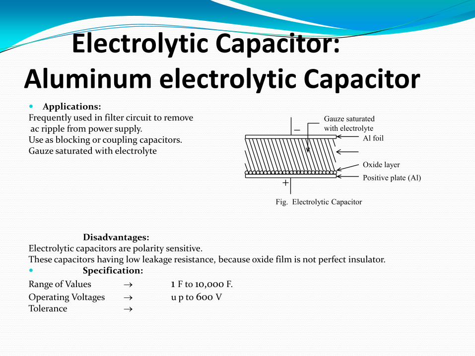
Electrolytic Capacitor:Aluminum electrolytic Capacitor Applications:Frequently used in filter circuit to removeac ripple from power supply.Use as blocking or coupling capacitors.Gauze saturated with electrolyte
Disadvantages:Electrolytic capacitors are polarity sensitive.These capacitors having low leakage resistance, because oxide film is not perfect insulator. Specification:
Range of Values 1 F to 10,000 F.
Operating Voltages u p to 600 VTolerance
Gauze saturated
with electrolyte
Fig. Electrolytic Capacitor
Al foil
Oxide layer
Positive plate (Al)

Tantalum Capacitors:Advantages:
Stable capacitance –
Low dc leakage current
Low impedance at high freq.
Small in size.
Tolerate exchange of Polarity of capacitor.
Disadvantages:
Expensive
Available only for low voltage ratings.
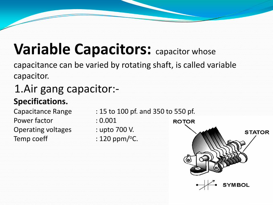
Variable Capacitors: capacitor whose
capacitance can be varied by rotating shaft, is called variable capacitor.
1.Air gang capacitor:-Specifications.Capacitance Range : 15 to 100 pf. and 350 to 550 pf.Power factor : 0.001Operating voltages : upto 700 V.Temp coeff : 120 ppm/oC.

2. Trimmer
Specification:
Range of Value : 5 to 30pf.
Power factor : 0.001
Operating voltages : up to 500V.
F ix e d v a n e
F ix e d v a n e
R o ta tin g /
m o v in g v a n e
