study on permanent manget temperature estimation of … · study on permanent manget temperature...
TRANSCRIPT

EVS28 KINTEX, Korea, May 3-6, 2015
Study on Permanent Manget Temperature Estimation of PMSM for
EV Traction
Suyeon Cho1, Donghyun Seo2, Waegyeong Shin2, Ju Lee3 1(corresponding author) Convergent System Safety Technology R&D Center, Reliability & Safety R&D Division, Korea Automotive
Technology Institute, 303 Pungse-ro, Pungse-myeon, Dongnam-gu, Cheonan-si, Chungnam, 330-912, Korea, [email protected] 2Convergent System Safety Technology R&D Center, Reliability & Safety R&D Division, Korea Automotive Technology Institute, 303
Pungse-ro, Pungse-myeon, Dongnam-gu, Cheonan-si, Chungnam, 330-912, Korea 3Department of Electrical Engineering, Hanyang Univrtsity, 222 Wangsimni-ro, Seongdong-gu, Seoul, 133-791, Korea
Introduction
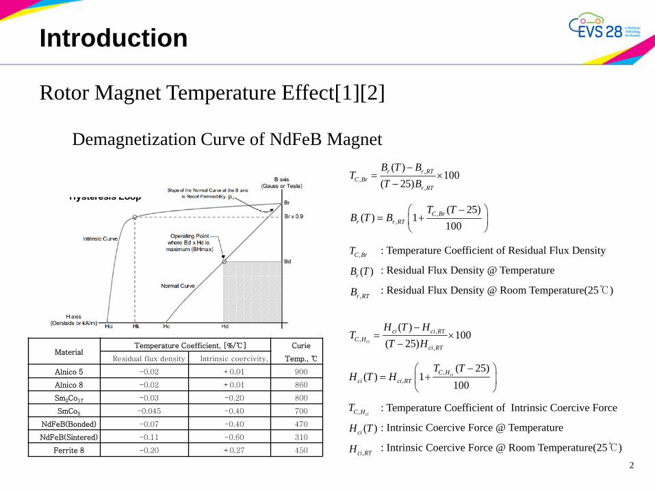
Rotor Magnet Temperature Effect[1][2]
Demagnetization Curve of NdFeB Magnet
2
,,
,
( )100
( 25)r r RT
C Brr RT
B T BT
T B−
= ×−
,,
( 25)( ) 1
100C Br
r r RT
T TB T B
− = +
,C BrT
( )rB T
,r RTB
,,
,
( )100
( 25)ci
ci ci RTC H
ci RT
H T HT
T H−
= ×−
,,
( 25)( ) 1
100ciC H
ci ci RT
T TH T H
− = +
, ciC HT
( )ciH T
,ci RTH
Material Temperature Coefficient, [%/℃] Curie
Temp., ℃ Residual flux density Intrinsic coercivity,
Alnico 5 -0.02 +0.01 900
Alnico 8 -0.02 +0.01 860
Sm2Co17 -0.03 -0.20 800
SmCo5 -0.045 -0.40 700
NdFeB(Bonded) -0.07 -0.40 470
NdFeB(Sintered) -0.11 -0.60 310
Ferrite 8 -0.20 +0.27 450
: Temperature Coefficient of Residual Flux Density
: Residual Flux Density @ Temperature
: Residual Flux Density @ Room Temperature(25℃)
: Temperature Coefficient of Intrinsic Coercive Force
: Intrinsic Coercive Force @ Temperature
: Intrinsic Coercive Force @ Room Temperature(25℃)
Introduction
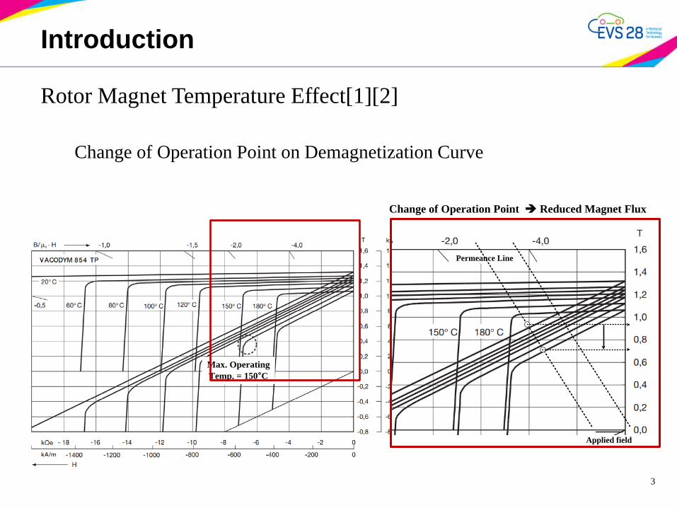
Rotor Magnet Temperature Effect[1][2] Change of Operation Point on Demagnetization Curve
3
Max. Operating Temp. = 150°C
Permeance Line
Applied field
Change of Operation Point Reduced Magnet Flux

Introduction
Rotor Magnet Temperature Effect[1][2] Change of Inductance
4
Finite element analysis results against rotor permanent magnet temperature of PMSM
(a) Room temperature condition(25℃) (b) High temperature condition(125℃)

Parameter Estimation Model
5
Discrete Z-domain PMSM voltage equation[3]-[6]
2
1
[ ( ) ( )]( ) d dd
d v z e zi zz d
−=
−
2
1
[ ( ) ( )]( ) q q
q
q v z e zi z
z q−
=− 1 2
1,
a sa s q
q
R TR T LL
a
eq e qR
−− −
= =
1 21,
a sa s dd
R TR T LL
a
ed e dR
−− −
= =
Z-domain equations(Zero-Order-Hold)
1 211 ,
a sa s dd
R TR T LL a s s
d a d
R T Ted e dL R L
−− −
= − =
1 211 ,
a sa s q
q
R TR T LL a s s
q a q
R T Teq e qL R L
−− −
= − =
Euler Approximation
Time sequence form
{ }*1 2( ) ( 1) ( 1) ( 1)d d d di n d i n d v n e n= − + − − −
( 1) ( 1)d r q qe n L i nω− = − −
1 21 ,a s s
d d
R T Td dL L
−
{ }*1 2( ) ( 1) ( 1) ( 1)q q q qi n q i n q v n e n= − + − − −
1 21 ,a s s
q q
R T Tq qL L
−
( 1) ( 1)q r d d r fe n L i nω ω φ− = − +

Online - Parameter Estimation
I. Magnetic Flux Estimation[7],[8]
Steepest Descent Method
{ }*1 2( ) ( 1) ( 1) ( 1)q q q qi n q i n q v n e n= − + − − −
1 21 ,a s s
q q
R T Tq qL L
−
{ }*1 2
ˆ ˆ( ) ( 1) ( 1) ( 1)q q q qi n q i n q v n e n= − + − − −
ˆ( ) ( ) ( )f q qe n i n i nφ = −
21( ) ( )2f f
V n e nφ φ =
2
ˆ( ) ( ) ( )( )ˆˆˆ( ) ( )( )
f f
f
q
q qq
V n V n i nJ q e n
e n e ni nφ φ
φ
∂ ∂ ∂= = =∂ ∂∂
ˆˆˆ ( 1) ( 1) ( 1) ( 1)q r d d r fe n L n i n nω ω φ− = − − + −
Magnet Flux Estimator
: Estimation Error
: Error Function
2ˆˆ(̂ 1) ( ) ( ) ( )fq q qe n e n J e n q e nφγ γ+ = − = −
,ˆ(0) (0) (0)q r d d r f inite L iω ω φ= +0 :n =
0 :n > 2ˆˆ(̂ 1) ( ) ( ) ( )fq q qe n e n J e n q e nφγ γ+ = − = −
√ Stability condition in selecting adaptation gain
22,max
20q
γ< <
( ) ( 1) ( ) 0f f f
V n V n V nφ φ φ + − <
ˆ ( )ˆ ˆ( ) ( ) ( )qf d d
r
e nn L n i nφ
ω= −

Online - Parameter Estimation
II. Inductance(Ld, Lq) Estimation[7],[8]
Affine Projection Algorithm(Adaptive Filter)
( ) ( ) ( )Ty n R n nθ=
ˆ( ) [ ( ) ( 1) ( 1)]Te n y n R n nθ= − − −
( 1) ( )ˆ(̂ ) ( 1) , {0,2}, 0( 1) ( 1)T
R n e nn nR n R nµθ θ µ δ
δ−
= − + ∈ ≈+ − −
{ }*1 2( ) ( 1) ( 1) ( 1)d d d di n d i n d v n e n= − + − − −
{ }*1 2( ) ( 1) ( 1) ( 1)q q q qi n q i n q v n e n= − + − − −
1 21 ,a s s
d d
R T Td dL L
−
1 21 ,a s s
q q
R T Tq qL L
− 1 2ˆˆ 1 ,ˆˆa s s
q q
R T Tq qL L
− =
1 2ˆˆ 1 ,ˆˆ
a s s
d d
R T Td dL L
−
ˆˆ( ) ( ) ( )Ty n R n nθ= Estimator
APA algorithmUpdate equation ( )e n
( )TR n
ˆˆ( ) ( 1) ( 1)Ty n R n nθ= − −
( 1) ( )ˆ(̂ ) ( 1)( 1) ( 1)T
R n e nn nR n R nµθ θ
δ−
= − ++ − −
( )y n
ˆ( )nθ
ˆ( )y n
Z-1

Online - Parameter Estimation
II. Inductance(Ld, Lq) Estimation[7],[8]
Affine Projection Algorithm(Adaptive Filter)
{ }*1 2( ) ( 1) ( 1) ( 1)d d d di n d i n d v n e n= − + − − −
1 2ˆˆ( 1) 1 , ( 1)ˆˆ ( 1) ( 1)
a s s
d d
R T Td n d nL n L n
− − −− −
ˆ( ) ( ) ( )dL d de n i n i n= −
{ }*1 2
ˆˆˆ ˆ( ) ( 1) ( 1) ( 1) ( 1) ( 1)d d d di n d n i n d n v n e n= − − + − − − −
ˆˆ ( 1) ( 1) ( 1)d r q qe n L n i nω− = − − −
* ˆ( 1) [ ( 1), ( 1) ( 1)]d
TL d d dR n i n v n e n− = − − − −
1 2ˆˆˆ ( 1) [ ( 1), ( 1)]
d
TL n d n d nθ − = − −
{ }*1 2( ) ( 1) ( 1) ( 1)q d q qi n q i n q v n e n= − + − − −
{ }*1 2
ˆ ˆˆˆ( ) ( 1) ( 1) ( 1) ( 1) ( 1)q q q qi n q n i n q n v n e n= − − + − − − −
ˆˆˆ ( 1) ( 1) ( 1) ( 1)q r d d r fe n L n i n nω ω φ− = − − + −
ˆ( ) ( ) ( )qL q qe n i n i n= −
* ˆ( 1) [ ( 1), ( 1) ( 1)]q
TL q q qR n i n v n e n− = − − − −
1 2ˆ ˆˆ( 1) [ ( 1), ( 1)]
q
TL n q n q nθ − = − −
1 2ˆˆ( 1) 1 , ( 1)ˆˆ( 1) ( 1)a s s
q q
R T Tq n q nL n L n
− − −− −

Verification by Simulation
9
0.05
0.1
0.15
0.2
0.25
0.3
0.35
0.4
0 5 10 15 20 25 30 35 40 45 50
Est
. PM
flux
link
age[
Wb]
N Step
Motor Speed = 1000RPMCurrent = 6A@15degPhi_init=0.1WbPhi_real = 0.189WbTs = 0.001sec
-0.02
-0.015
-0.01
-0.005
0
0.005
0.01
0.015
0.02
25 30 35 40 45 50
Est
imat
ion
Err
or [W
b]
N Step
Motor Speed = 1000RPMCurrent = 6A@15degPhi_init=0.1WbPhi_real = 0.189WbTs = 0.001sec
0
0.0025
0.005
0.0075
0.01
0.0125
0.015
0.0175
0.02
0 10 20 30 40 50 60 70 80 90 100
Est
. Ind
ucta
nce
[H]
N Step
Motor Speed = 1000RPMCurrent = 6A@15degLd_init=0.0045HLq_init=0.006HTs = 0.0002sec
Ld_est
Ld_real = 0.006H
Lq_real = 0.009H
Lq_est
-0.002
-0.0015
-0.001
-0.0005
0
0.0005
0.001
0.0015
0.002
20 30 40 50 60 70 80 90 100
Est
imat
ion
Err
or [H
]
N Step
Ld_est_error Lq_est_error
Motor Speed = 1000RPMCurrent = 6A@15degLd_init=0.0045HLq_init=0.006HTs = 0.0002sec

Experiment
I. IPMSM Specifications and Test Bench for Experiment
10
Parameter Value Unit
Motor Type Interior PM Synchronous Motor
Rated Output 750 WRated Torque 3.58 NmRated Speed 2000 rpmMax Speed 3000 rpmDC Voltage 200 V
Phase Curent max 6 ApeakBack EMF coefficient@25℃ 39.634 Vpeak/krpm
No. of phase 3No. of Pole 4No. of Slot 24Silicon Steel S60(0.5t)Magnet Type NdFeB/Parallel Magnetization
Magnet Thickness 3 mmMagnet Length 38 mm
Stator Outer Diameter 60.9 mmStator Inner Diameter 35 mm
Rotor Outer Diameter(max) 34.4 mmAirgap Length 0.6 mmStack Length 90 mm
Dynamo Controller
DC Power Supply
Dynamo Set(Torque Tranducer+Servo Motor)
OscilloscopeComputer
Mobile Recoder(Temperature monitor)
Motor Controller(DSP + Power Stack)
Motor Controller(DSP + Power Stack)
IGBT Module
Gate Driver TMS320F28335DSP Board
Dynamo Set(Torque Tranducer+Servo Motor)
Torque Tranducer
Servo Motor
PMSM
(a) (b)

Experiment
II. Rotor magnet temperature variation
11
0.193Wb 0.184Wb 0.177Wb

Experiment
III. Parameter estimation results
12
Ld_est_Flag
Ld_init=0.003H
5V/divDA_out = 1.358VDA_scale = 1/200
Ld_est Ld_est=0.00679H
Lq_est_Flag
Lq_init=0.012H
5V/divDA_out = 1.820VDA_scale = 1/200
Lq_est Lq_est=0.0091H
Phi_est_Flag
Phi_estPhi_init=0.1Wb
Phi_est=0.189Wb
5V/divDA_out = 3.784DA_scale = 1/20

Experiment
IV. Control results by proposed method
13
0
0.6
1.2
1.8
2.4
3
3.6
4.2
4.8
5.4
6
-3 -2.7 -2.4 -2.1 -1.8 -1.5 -1.2 -0.9 -0.6 -0.3 0
Q-a
xis c
urre
nt [A
]
D-axis current [A]
Idq_fdb@Medium rotor temperature Idq_fdb@High rotor temperature
(1)(2)
4.8
5.1
5.4
5.7
6
-2.7 -2.55 -2.4 -2.25 -2.1
Q-a
xis c
urre
nt [A
]
D-axis current [A]
Idq_fdb@Medium rotor temperature Idq_fdb@High rotor temperature
β=22.4°Ia=5.97A
3
3.25
3.5
3.75
4
4.25
4.5
-0.4 -0.35 -0.3 -0.25 -0.2 -0.15
Q-a
xis c
urre
nt [A
]
D-axis current [A]
Idq_fdb@Medium rotor temperature Idq_fdb@High rotor temperature
β=4.21°
β=3.47°
Ia=3.86A
Ia=3.72AMedium rotor temp.
High rotor temp.
Traces of current at medium and high rotor temperature

Conclusion
14
Parameters affected by the rotor temperature variation of the IPMSM were analyzed. In addition to demagnetization characteristics of the permanent magnet, Parameters of IPMSM was estimated by proposed method(numerical technique and adaptive filter) for compensating rotor magnet temperature. From the experiment results of parameter estimation and torque control, the proposed method was verified.
Acknowledgments & References
15
This research was financially supported by the “Green electronic car component development and research foundation construction program” through the Ministry of Trade, Industry & Energy(MOTIE) and Korea Institute for Advancement of Technology(KIAT)
ACKNOWLEDGMENT
REFERENCES [1] Tomy Sebastian, "Temperature Effects on Torque Production and Efficiency of PM Motors Using NdFeB Magnets,"
IEEE Transactions on Industry Applications, Vol. 3 1, No. 2, pp. 353~357, 1995. [2] PD002 VACODYM-VACOMAX, 2007, VACUUMSCHMELZE社 [3] Henrik Neugebauer, "Parameter Identification of a Permanent Magnet Synchronous Motor," Master's Thesis,
Department of Signals&Systems, Chamers University of Technology, 2012. [4] D. S. Oh, K. Y. Cho, and M. J. Youn, “A discretized current control technique with delayed input voltage feedback
for a voltage-fed PWM inverter,” IEEE Trans. Power Electron., vol. 7, no. 2, pp. 364–373, Apr.1992. [5] T. H. Liu, C. M. Young, and C. H. Liu, “Microprocessor-based controller design and simulation for a permanent
magnet synchronous motor drive,” ZEEE Trans. Industrial Electronics, vol. 1E-35, no. 4, November 1988, pp. 516-523.
[6] B. K. Bose and P. M. Szczesny, "A microcomputer based control and simulation of an advanced IPM synchronous machines drive system for electric vehicle propulsion," IEEE Trans. IE, vol. 35, no. 4, pp. 547-559, 1988. [7] Yasser Abdel-Rady Ibrahim Mohamed, Member, IEEE,and Tsing K.Lee, "Adaptive Self-Tuning MTPA Vector
Controller for IPMSM Drive System", IEEE TRANSACTIONS ON ENERGY CONVERSION, VOL. 21, NO. 3, SEPTEMBER 2006.
[8] Donald W. Marquardt, "An Algorithm for Least-Squares Estimation of Nonlinear Parameters" Journal of the Society for Industrial and Applied Mathematics, Vol.11, No.2, pp.431-441, Jun, 1963.