study of properties of niti alloy after electrone beam...
TRANSCRIPT

June 3rd - 5th 2015, Brno, Czech Republic, EU
STUDY OF PROPERTIES OF NiTi ALLOY AFTER ELECTRONE BEAM ZONE MELTING
MADAJ Michal1, SZURMAN Ivo1, DRÁPALA Jaromír1, VONTOROVÁ Jiřina1, POHLUDKA Martin1
1VŠB - Technical University of Ostrava, Ostrava, Czech Republic, EU
Abstract
The NiTi alloy was remelted by electron beam zone melting. The initial state of the NiTi samples was after
swaging. After electron beam floating zone melting samples were prepared for optical metallographic analysis,
scanning electron microscopy analysis and EDX analysis. Next analysis was made to determine the
concentration of interstitial elements (C, O, N). The obtained results were compared to NiTi alloys prepared
previously by other technologies (centrifugal casting, and so on).
Keywords: NiTi alloy, electron zone melting, NiTi microstructure, Nitinol, SME
1. PROPERTIES AND FABRICATION OF NiTi BASED ALLOYS
From the well-known Shape Memory Alloys (SMA) the most extended investigation is devoted to an
intermetallic compound with body centred cubic lattice called Nitinol, which is NiTi based alloy. Its properties,
such as good corrosion resistance and biocompatibility, make it an ideal material for biocompatible
applications, such as orthodontic wires, stents or orthopaedic implants. This intermetallic compound is
paramagnetic with low permeability at constant temperature range from 160 to 538 °C. The basics physical
properties of NiTi based alloys are presented in Table 1 [1, 2, 3].
Table 1 Basic physical properties of equiatomic composition of NiTi based alloys [2]
Temperature melting of various equiatomic composition of NiTi based alloys (°C)
1992 – 2117
Density (kg/m3) 6449
Module of elasticity (GPa) 69,63
Module of rigidity (GPa) 26,20
Shape Memory Alloy effect was discovered only for equiatomic composition of NiTi based alloy (i.e. 50 at. %
of nickel and 50 at. % of titanium), specifically for the B2-phase which exhibits maximally temperature of
martensitic phase transformation of approx. 120 °C. Martensite phase obtained from twinning mechanism after
transformation shows compatible crystallographic structure which is changed in dependence on composition
and transformation temperature between B2 structure for the base phase (CsCl type) and martensitic phase
with monoclinic lattice or B19ꞌ structure [1, 3, 4]. Maximum temperature of martensite transformation is approx.
70 °C for equiatomic composition of NiTi based alloy. When the Ni content in equiatomic composition is
reduced, then the temperature of martensitic transformation does not change. If the Ni content increases over
50 at. % the transformation temperature starts to decrease sharply until -40 °C for 51 at. % of Ni. If the Ni
content increases up to 55 at. % the transformation temperatures are between -10 °C and 60 °C. In comparison
with stainless steel this alloy has an excellent corrosion resistance in saltwater or salt spray. The alloy is stable
during heat treatment and it is easy to control its transformation temperature, too. It is determinant for
fabrication of complicated shapes during heat treatment. If the composition is changed, then martensitic
transformation can occur at room temperature which results from SME to pseudoelasticity. NiTi based alloys
show fully renewable transformation deformation up to 8 % [1]. The Fig. 1 presents an equilibrium diagram of
Ti-Ni which shows sub-stoichiometric concentrations of the B2 phase for alloys in bi-phase region Ti2Ni + NiTi

June 3rd - 5th 2015, Brno, Czech Republic, EU
matrix. In the case, when the concentration is higher than stoichiometric, it is necessary to apply quenching of
the B2 phase with consequential annealing at the temperature of 600 °C. The result is precipitation of TiNi3 or
Ti2Ni3. After precipitation of phases Ni content is reduced while martensitic transformation temperature
increases [4].
Fig. 1 Equilibrium diagram of Ti-Ni [4]
Precipitation process of Ni-rich alloys at 400 °C enables lenticular precipitation of Ti3Ni4 phase. On the basis
of the formation strain fields from the precipitates of Ti3Ni4 formation of R-phase between austenitic and
martensitic phase can result. The R-phase disappears after annealing at high temperatures [2]. This transition
phase created from martensitic transformation through small elongation of the B2 structure in the direction of
<111> shows only little hysteresis with small memory effect. If the transition R-phase after cooling is created
as first the following transformations scheme will be respected: B2 → R-phase → Martensite. First the
martensitic transformation will be created so the R-phase will not be visible. After heating a reversible
transformation process takes place: Martensite → R-phase → B2. The R-phase formation is basically
influenced by substitution of few at. % of nickel to iron or aluminum by formation of Ti3Ni4 precipitates at aging
of Ni-rich alloy, by annealing below recrystallization temperature after cold forming, by cyclical heat stress or
by alloying with the third component. The R-phase is used where low hysteresis is needed or for maintaining
the memory effect during small deformation of approx. 1% [3, 4].
If oxygen is present in the alloy as interstitial element its amount has influence of martensite start
transformation temperature which is linearly decreasing with the increasing oxygen contents. The oxygen
solubility in solid solution of NiTi is really small (0,045 at. %) and therefore the alloys containing oxygen above
0,045 at. % are solidifying during cooling of the melt as primary NiTi phase and eutectic mixture of solid solution
(NiTi) and oxide (Ti4Ni2O). Oxygen therefore binds to itself twice as much Ti as Ni in NiTi phase of the type B2.
This results in an increased Ni content in the remaining phase [5]. Reduction content of gases in the alloy
during EBFZM can be difficult to achieve due to creation of thin oxide layer of the surface of the alloy [6].
If the NiTi alloy contains carbon the martensite start transformation temperature also decreases with the
increase of carbon contents. Carbon is precipitated in the alloy as TiC phase and present Ti conent in the
matrix is decreased. At the same time Ni contents is increased too. Even a small amount of carbon solute in
matrix causes decrease of the martensite start temperature transformation down to 258 °C. Alloy containing
carbides has important effect on yield strength and yield stress. The carbide content in melting alloy depends
on the melt temperature and carbide content after melting in graphite crucible is in the range of approx. 200 -
500 ppm which has not influence on the memory effect and properties of the alloy [5].
Weight percent Nickel
Atomic percent Nickel
June 3rd - 5th 2015, Brno, Czech Republic, EU
What concerns the mechanical properties of NiTi based alloys, these materials are ductile below the
transformation temperature and they can be plastically deformed in relatively low strain. Mechanical properties
of NiTi based alloy are shown in Table 2. Nitinol has good strength, ductility, and fatigue properties. Tensile
strength and yield strength is increasing with decreasing temperature and strength is decreasing with
temperature increasing up to 327 °C. Decrease of strength is accelerating with temperature above 377 °C [2,
5]. Elongation is relatively constant up to -100 °C naturally only if the temperature is really fast reduced. Ductility
is increased with relatively low rates up to 371 °C and up to the temperature is increased higher rate. At the
temperature above 526 °C the alloy has high ductility, low yield strength and strain rate, and high sensitivity to
the change of strain rate. At the temperature of approx. 626 °C ductility is higher than 100 % of the initial value.
Between the temperatures of approx. 21 - 593 °C the yield strength depends on strain hardening which is
really rapidly increasing with the temperature. Below 21 °C Nitinol has large plasticity due to the martensite
transformation. Impact strength of Nitinol is approx. by 25 % higher at -80 °C than at room temperature. Fatigue
strength of NiTi is dependent on microstructure and lattice defects are present. If NiTi contains only small Ti3Ni4
precipitations its fatigue strength is lower as compared to the same structure with high dislocation density
caused during cold forming [2, 3].
Table 2 Mechanical properties of equiatomic composition of NiTi based alloys [2]
Tensile strength (MPa) 566 – 966
Yield strength Rp02 (MPa) 227 – 558
Elongation ε (%) 10
Hardness by Rockwell; diamond cone with load of 600 N (HRA) 65 – 68
Impact strength (kJ × m2) 32, 53
High cycle fatigue at 25 × 106 cycles (MPa) 483
1.1. Fabrication of NiTi based alloys
Molten titanium is highly reactive with oxygen therefore NiTi based alloys are melted in high vacuum or in inert
atmosphere. Vacuum induction melting or plasma arc melting are the most frequently used methods. Other
used methods are electron beam melting or arc melting in inert atmosphere. The advantage of the first method
consists in obtaining of structural homogeneity in the entire cross section of the ingot. It results from induction
mixing of the melt. The crucibles used for melting these alloys are mainly from graphite, or from calcium oxide
(CaO). The aluminum oxide or magnesium oxide are not suitable as material for crucibles because molten
titanium reacts with oxygen included in crucible and it contaminates the melted alloy. In the case when graphite
crucible is used contamination of the alloy takes place. This contamination is indeed negligible if there is no
melting process at the temperature higher than 1450 °C (occurrence of increased carbon contents in the alloy)
[5].
Melting by electron beam uses kinetic energy of electrons incident beam acting onto melted material. Basic
material is melted in the water-cooled copper crystallizer. The alloy solidifies in the lower part of the crystallizer
and then it is poured out through the crystallizer bottom. This melting process provides the lowest content of
impurities thanks to the refining effect of the high vacuum and high temperature. The composition and
homogeneity of the ingot is not adequate because the alloy is directionally solidifying from the bottom of the
crystallizer. Vaporization of the alloy due to high temperature is complicating control of the composition. That
method is used at preparation of NiTi based alloys in which precise proceeding temperature of martensitic
transformation is not needed [5].
The methods of arc melting are divided two types. The first type uses for melting process by a non-fusible
electrode and the second process uses fusible electrode which is made the same material as the melt. In the
first case tungsten electrode is used and melting process takes place in Cu mould. The final product has then
June 3rd - 5th 2015, Brno, Czech Republic, EU
the shape as “pit”. In order to achieve better homogeneity it is necessary to turn around to back solidified “pit”
and remelted. In the second case the electrode is made from same material as the melt and it melts and falls
into the melt. [5].
In the case when plasma arc melting is used the melting is performed by an electron beam emitted from plasma
gun (cathode). Electron emitting is milder in comparison with high-voltage electron beam melting or arc melting
in inert atmosphere. The result is lower loss of components in alloy. The alloy is then more homogeneous even
in case of use of the water-cooled Cu crucible [5].
1.2. Forming operation of NiTi based alloys
The alloy is commercially produced in numerous variants from the wires, plates, rods up to tubes and sheets.
Although the alloy has good forming properties at the temperature of 526 °C, the optimal temperature for hot
forming is approx. 850 °C. During the hot forming light surface oxidation can occur. Extrusion, rolling or
stamping at the temperature range from 600 to 900 °C can be used for hot forming of Nitinol. The final rolling
to strips or wire drawing can be made at the temperature of approx. 400 °C [2, 5]. In comparison with hot
forming process the cold forming process is fully dependent on the composition. With increase of Ni content
formability of these materials decreases, especially for Ni content higher than 51 at. %. It is result of higher
strain hardening. Yield strength for annealed NiTi based alloy is not higher than 100 MPa (similarly as for the
soft annealed Cu or Al). If is NiTi annealed wire to deformed its tensile strength increased at ~10 % of strain
and at ~40 % or strain is 1000 MPa. In the case of cold wire drawing the tensile strength is higher than 1500
MPa [5].
2. EXPERIMENTAL PROCEDURES
For experimental determination of structural characteristic a NiTi based alloy was created with equiatomic
composition of its components. As the input materials cathode nickel was used with purity 4N and shaped
rolled titanium of purity 2N8. The content of nickel was 50,85 at. % and content of titanium was 49,15 at. %.
The total amount of alloy was 705 g. The original alloy was prepared by vacuum induction melting process in
graphite crucible. The output sample was 225 mm long and had diameter of 20 mm. Hot swaging was then
applied to the alloy without inert atmosphere. Four reductions were applied and the alloy was annealed
between individual steps of swaging. The final diameter was 10 mm and length was 350 mm. The swaging
was followed by Electron Beam Floating Zone Melting (EBFZM) where a narrow zone was melted using
electron emission. After that the melting zone passed through the required length of the NiTi rod. This
technology is also suitable for preparation of single crystals made of high melting metals [7]. The alloy was
remelted by a single passage through the melting zone. The length of remelted rod was 150 mm. Travel speed
of the molten zone was 3 mm/min. The average value of vacuum was 8,3 × 10⁻⁴ Pa, cathode voltage was 6
kV, current cathode was from 13,86 A to 14 A and cathode emission was from 35 mA at the beginning of the
rod to 29 mA in the end of melting.
After EBFZM three samples were cut from the alloy for metallographic analysis. The sample 1 was taken from
the transition zone between the formed and remelted area, it was longitudinal section. Sample 2 was taken
from the centre of the remelted rod, it was cross section and last sample 3 was taken as longitudinal section
(Fig. 2).
June 3rd - 5th 2015, Brno, Czech Republic, EU
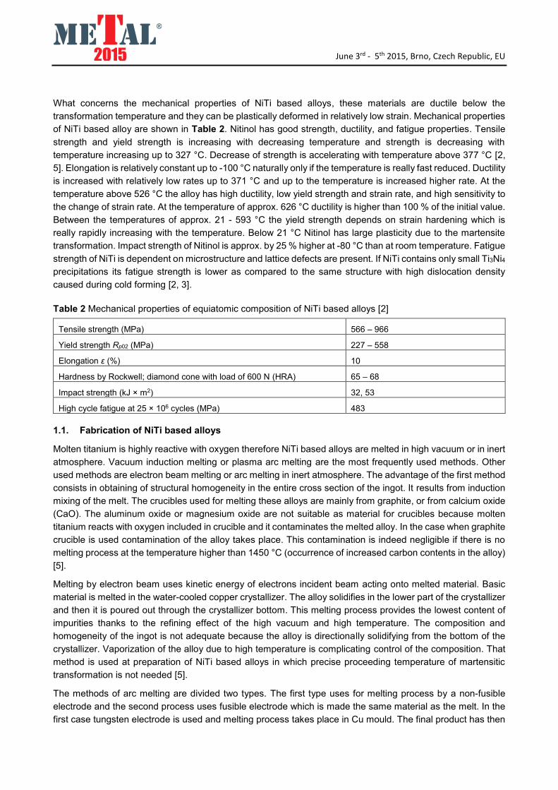
Fig. 2 Sample of NiTi based alloy after EBFZM
The samples were subjected to metallographic analysis with uses of optical microscope. All the samples were
ground using abrasive paper discs with SiC. Polishing was applied using water suspension of Al2O3.
Microstructure was developed by an etching agent 1HF : 4HNO3 : 5H2O and observation of the microstructure
and taking pictures of it was realised on the microscope Olympus GX 51, equipped with the digital camera DP
12. The samples were then taken for EDX analysis and the last analysis was determination of interstitial
elements in the alloy (O2, N2 a C). The interstitial elements were analysed by elementary analysis (EA) using
the ELTRA ONH - 2000 and ELTRA CS - 2000 analysers on the sample 2.
3. RESULTS AND DISCUSSIONS
On the surface of the NiTi rod remelted by EBFZM macro-segregation was detected which was seen only in
the second part of the rod. It was result of redistribution of impurities and elements during EBFZM. Sub-gains
were seen on the surface of remelted rod too, see the Fig. 2. This fact was confirmed by the cross section of
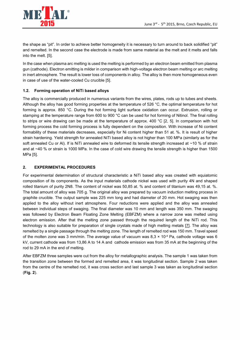
the sample 2. In the Fig. 3 the microstructures of NiTi alloy are shown. Fig. 3 a) shows really clear transition
between swaging part and EBFZM part of the sample. After EBFZM precipitated Ti2Ni phase and carbide TiC,
were found in microstructure which got into the alloy from the graphite crucible.
Fig. 3 Microstructure of NiTi based alloy a) sample 1, longitudinal section, scale 500 μm; b) sample 2, cross
section, scale 100 μm; c) sample 3, longitudinal section, scale 100 μm
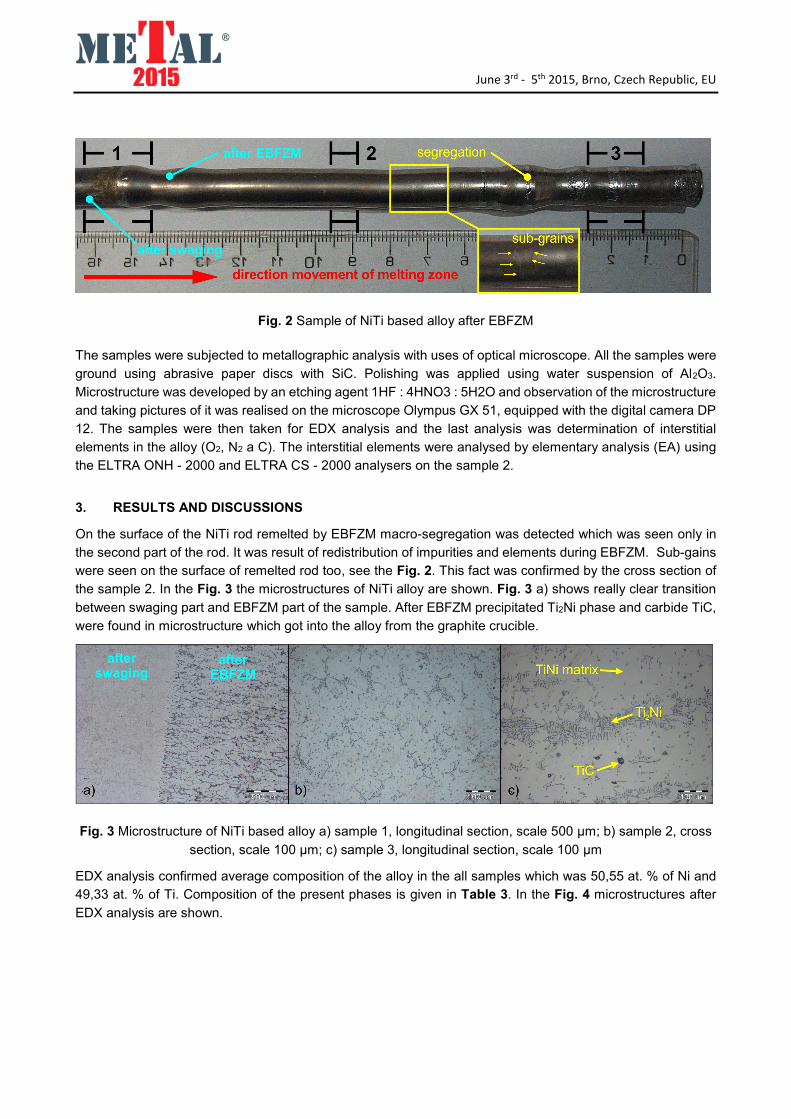
EDX analysis confirmed average composition of the alloy in the all samples which was 50,55 at. % of Ni and
49,33 at. % of Ti. Composition of the present phases is given in Table 3. In the Fig. 4 microstructures after
EDX analysis are shown.
June 3rd - 5th 2015, Brno, Czech Republic, EU
Table 3 Average composition of NiTi based alloy phases after EDX analysis
Phase at. % Ti at. % Ni at. % C
NiTi matrix 49 51
Ti2Ni 66,19 33,81
TiC 78,07 41,93
Fig. 4 Microstructure of NiTi based alloy, longitudinal section of the sample 3
The results of gas analysis after EBFZM are seen in Table 4. In comparison to vacuum induction melting the
gas content is higher than after EBFZM. It could be expected that gas content will be lower because EBFZM
process runs under high vacuum (10-4 Pa) but it is not so. During application of EBFZM no escape of gases
from the melt by the sputter droplets from the melt was visible.
Table 4 Analysis of interstitial elements in NiTi based alloy after EBFZM
Technology O2 wt. % N2 wt. % C wt. %
Vacuum induction melting 0,065 0,004 0,039
EBFZM 0,145 0,037 0,108
CONCLUSIONS
In the second part of the rod macrosegregations were seen in the structure after applied EBFZM. Inside of the
structure the alloy structure sub-grains were distinctly seen. During EBFZM no significant changes of
composition along the longitudinal section of the rod took place. It was found that the gas content in the NiTi
based alloy was higher after the applied EBFZM. Higher content of gases in the alloy might have caused
creation of thin oxide layer on the surface of rod during swaging without inert atmosphere. It will be necessary
to make other experiments in order to explain higher gas content in the NiTi based alloys.
ACKNOWLEDGEMENTS
This paper was created at the Faculty of Metallurgy and Materials Engineering in the Project
No. LO1203 "Regional Materials Science and Technology Centre - Feasibility Program" funded by the
Ministry of Education, Youth and Sports of the Czech Republic.

June 3rd - 5th 2015, Brno, Czech Republic, EU
REFERENCES
[1] LAGOUDAS, D. C. Shape Memory Alloys: Modeling and Engineering Applications. New York: Springer
Science+Business Media, LLC, 2010, 436 p.. ISBN 978-0-387-47684-1.
[2] EVERHARD, J. L. Engineering Properties of Nickel and Nickel Alloys. New Jersey: Springer, 2012, 229 p.. ISBN
978-1-4684-1886-6.
[3] YAMAUCHI, K. et al. Shape Memory and Superelastic Alloys: Applications and Technologies. Cambridge: Woodhead
Publishing Limited, 2011, 232 p.. ISBN 978-1-84569-707-5. Woodhead Publishing Series in Metals and Surface
Engineering.
[4] LEXCELLENT, C. Shape-Memory Alloys Handbook. Croydon (Great Britain): ISTE Ltd and John Wiley & Sons, Inc.
2013, 400 p.. ISBN 978-1-84821-434-7.
[5] OTSUKA, K. a C. M. WAYMAN. Shape Memory Materials. Cambridge: Cambridge University Press, 1998, 298 p..
0-52-1-44487-X.
[6] SZURMAN, I. R. KOCICH a M. KURSA. Shape Memory Alloys: Fabrication and processing. Herstellung (Německo):
LAP LAMBERT Academic Publishing, 2012, 102 p.. 978-3-848-2535-8.
[7] SKOTNICOVÁ, K. et al. Preparation and investigation of structural parameters of single crystals of low-alloyed alloys
on …. Advanced engineering materials. Wiley-VCH, 2013, 15 (10), 927-34. ISSN 1438-1656.