research open access design of splints based on the niti ...research open access design of splints...
TRANSCRIPT

RESEARCH Open Access
Design of splints based on the NiTi alloy for thecorrection of joint deformities in the fingersSergio Puértolas1, José M Pérez-García2,3,4, Luis Gracia1, José Cegoñino1, Elena Ibarz1, José A Puértolas5,Antonio Herrera2,3,4*
* Correspondence:[email protected] of Surgery, Universityof Zaragoza, Domingo Miral s/n,50009 Zaragoza, Spain
Abstract
Background: The proximal interphalange joint (PIP) is fundamental for the functionalnature of the hand. The contracture in flexion of the PIP, secondary to traumatismsor illnesses leads to an important functional loss. The use of correcting splints is thecommon procedure for treating this problem. Its functioning is based on theapplication of a small load and a prolonged stress which can be dynamic, staticprogressive or static serial.It is important that the therapist has a splint available which can release a constantand sufficient force to correct the contracture in flexion. Nowadays NiTi is commonlyused in bio-engineering, due to its superelastical characteristics. The experience ofthe authors in the design of other devices based on the NiTi alloy, makes it possibleto carry out a new design in this work - the production of a finger splint for thetreatment of the contracture in flexion of the PIP joint.
Methods: Commercial orthosis have been characterized using a universal INSTRON5565 machine. A computational simulation of the proposed design has beenconducted, reproducing its performance and using a model “ad hoc” for the NiTimaterial. Once the parameters have been adjusted, the design is validated using thesame type of test as those carried out on commercial orthosis.
Results and Discussion: For commercial splint the recovering force falls toexcessively low values as the angle increases. Angle curves for different lengths andthicknesses of the proposed design have been obtained, with a practically constantrecovering force value over a wide range of angles that vary between 30° and 150°in every case. Then the whole treatment is possible with only one splint, andwithout the need of progressive replacements as the joint recovers.
Conclusions: A new model of splint based on NiTi alloy has been designed,simulated and tested comparing its behaviour with two of the most regularly usedsplints. Its uses is recommended instead of other dynamic orthosis used inorthopaedics for the PIP joint. Besides, its extremely simple design, makes itsmanufacture and use on the part of the specialist easier.
Puértolas et al. BioMedical Engineering OnLine 2010, 9:49http://www.biomedical-engineering-online.com/content/9/1/49
© 2010 Puértolas et al; licensee BioMed Central Ltd. This is an Open Access article distributed under the terms of the CreativeCommons Attribution License (http://creativecommons.org/licenses/by/2.0), which permits unrestricted use, distribution, andreproduction in any medium, provided the original work is properly cited.

BackgroundThe proximal interphalange joint (PIP) is fundamental for the functional nature of the
hand. It is considered to be the functional epicentre, since 85% of total encompassment
when an object is grasped depends on this joint [1]. The contracture in flexion of the
PIP, secondary to traumatisms or illnesses leads to an important functional loss.
The use of correcting splints is the common procedure for treating this problem. Its
functioning is based on the application of a small load and a prolonged stress which
can be dynamic, static progressive or static serial [2]. Despite the force applied being
small and progressive the neighbouring joints should be evaluated before its use in
patients with systematic illnesses, as the splints increase the stress on the joints and
can cause finger edema [3]. This progressive application of forces on the PIP joint
stimulates the histic changes, which enable the elongation of the capsuloligamentous
structures until the correction of the deformity is achieved [4].
The straightening forces developed by static splints were analysed by Wu [5] and those
of the dynamic splints by Fess [6]. Both systems base the biomechanical action on the
application of three parallel forces. Later analysis [3] consider that the force released by
both systems is similar, and present the pressure exerted on the back of the damaged
joint (PIP), greater in the static systems, as the main inconvenience of both [3].
The materials used in both types of splints are to a great extent thermoplastics,
which in the short term suffer a change in resistance [7]; New materials such as
neoprene have been proposed by other authors [8], although with this proposed model
the inconvenience of covering all of the finger arises, something which can generate
the edema and be counterproductive.
Considering the effectiveness of the two systems, good results have been published for
both [9-12]. However it is fundamental to know the biomechanics of each system in
order to produce personalised devices adapted to the characteristics of each patient [3].
It is important that the therapist has a splint available which can release a constant
and sufficient force to correct the contracture in flexion. Nowadays NiTi is commonly
used in bio-engineering, due to its superelastical characteristics and its shape memory
[13]. The experience of the authors in the design of other devices based on the NiTi
alloy [14-17], makes it possible to carry out the proposed design in this work - the pro-
duction of a finger splint for the treatment of the contracture in flexion of the PIP joint.
This paper describes the characteristics of the splint designed, comparing its biome-
chanical behaviour with that of commercial dynamic splints regularly used to treat the
stiffness of the PIP joint.
MethodsThe first step consisted in characterising the biomechanical properties of the splints
that were to be used as reference. Two of the most regularly used splints have been
chosen: the LMB Spring Finger Extension Splint (splint 1) and the LMB Spring-Coil
Finger Extension Splint (splint 2).
We are dealing with two simple designs which basically consist of a torsion spring
with two angled arms which make it possible to fix and lock onto the finger (Figs. 1a
and 1b). The spring restoration torque is the origin of the forces applied to the
extremes of the splint, which are balanced with the reaction in the central section
(Fig. 1c).
Puértolas et al. BioMedical Engineering OnLine 2010, 9:49http://www.biomedical-engineering-online.com/content/9/1/49
Page 2 of 14

In order to characterise the recovering forces in the whole area in which the devices
act, we proceeded to carry out the respective bending tests in an INSTRON 5565 univer-
sal test machine by means of eccentric compression of the orthosis (Fig. 2). This test was
carried out instead of the 3-point bending test due to the fact that the 3-point test suf-
fers from interferences between the actuators making it impossible to arrive at angles
that are closed enough. Both tests were carried out with control in vertical movement at
a speed of 2 mm/min. During the tests data for both force (N) and displacement (mm)
were captured. Front view digital photos of the different positions of the extremes of the
orthosis every 0.5 mm of vertical movement have also been captured. Later, an analysis
of the photographs has been carried out using a computer program for image processing
in order to obtain the variation of the angle between the extremes of the orthesis in the
course of the tests. In this way, both the force-displacement graphs and the moment-
angle graphs can be obtained.
The proposed design uses a thin plate of NiTi, which is fixed onto the finger by
means of rings, which are responsible for transmitting the recovering force (Fig. 3).
The mechanism provides a practically unidimensional bending performance, such that
the device presents a mechanical response close to the intrinsic material behaviour.
This means that the moment-angle curve of the splint has a similar shape to the
Figure 1 Bort type splints: a) LBM Spring Finger Extension Splint; b) LMB Spring-Coil FingerExtension Splint; c) Force transmission mechanism for Bort type splints
Puértolas et al. BioMedical Engineering OnLine 2010, 9:49http://www.biomedical-engineering-online.com/content/9/1/49
Page 3 of 14

material tension-deformation curve. This curve is characterized by means of a tensile
test on the plate, carried out using the same INSTRON 5565 machine, observing a
wide area of restoration at a practically constant tension, which is presented in Fig. 4.
As far as the material is concerned, NiTi is an equiatomic alloy of nickel and titanium
(commercially known as Nitinol), discovered in the U.S. Naval Ordenance Laboratory
[18]. It belongs to a group of materials with shape memory (SMA). Basically, these
alloys have the attribute of being able to recover a previously defined form when the
material is subjected to an adequate thermal treatment; associated to this behaviour,
the material has a super elasticity which lends to the property of withstanding large
elastical deformations with relatively low tensions. This property is due to the change
of phase austenite-martensite-austenite which the material undergoes when it is
subjected to tension [19].
Figure 2 Bending test for Bort type splints
Figure 3 a) Prototype of the designed NiTi splint; b) Force transmission mechanism for thedesigned splint
Puértolas et al. BioMedical Engineering OnLine 2010, 9:49http://www.biomedical-engineering-online.com/content/9/1/49
Page 4 of 14

The action of the splints is directly related to the rigidity, and in the proposed design
the rigidity is directly related to the width, the thickness and the length, although all of
these geometric factors work in an uneven way. An increase in width supposes a linear
growth in the recovering force and a better finger support. However, the most impor-
tant factor used to control the force exerted by the splint is the plate thickness. The
device is very sensitive to thickness change, presenting a cubic rate influence. Hence,
the greater the thickness, the greater the effect of straightening and the smaller the
risk of rupture although it is more difficult to bend the splint and fit it in the volar
zone of the injured finger. On the contrary, if the thickness is reduced so is the
straightening effect and the risk of rupture increases, although it is easier to bend the
splint and fit it on the finger
To obtain a design which transmits a force adequate for the recovery of the original
position of the finger, a simulation by means of finite elements for a plate of these
dimensions 80 × 10 × 1 mm is carried out equivalent to the test undertaken for com-
mercial splints. For the behaviour of the material a proprietary developed user subrou-
tine is used, based on Auricchio`s models [19], in the Abaqus program [20], after
previously carrying out an adjustment of parameters from the results of the tensile test
(Fig. 4). In Table 1 the different parameters used in the simulation are gathered. The
model consists of 4455 nodes and 3200 hexaedric elements, type C3D8, with linear
approximation (80 in length, 10 in width and 4 in thickness). As for the boundary con-
ditions, initially a displacement of 1 mm in the centre of the plate is applied to later
apply the eccentric compression until reaching the maximum curvature, moment in
which the load is removed and a free restoration is produced.
The results of this first simulation applied recovering forces well above those corre-
sponding to the commercial splints that were analysed, so we proceeded to review the
initial design, either by adjusting the thickness of the plate or looking for alternative
designs as those shown in Fig. 5. With any one of the three proposed designs it is
Figure 4 Stress-strain curve for loading and unloading process corresponding to the NiTi alloy at 22°C
Puértolas et al. BioMedical Engineering OnLine 2010, 9:49http://www.biomedical-engineering-online.com/content/9/1/49
Page 5 of 14

possible to carry out an adjustment to the parameters in order to obtain recovering
forces within the desired range.
Finally, we proceeded to produce prototypes of the proposed splint, by means of
mechanized electroerosion, from plates with 1 mm of NiTi thickness (50.8 at %Ni, 49.2
at % Ti), supplied by the company Memory Metalle GMBH (Germany). The plates
with less thickness (up to 0.5 mm) were obtained by cold lamination of the cut plates,
followed by a annealing to eliminate the effects of cold lamination. Tests were then
carried on these prototypes equivalent to those done on the commercial splints ana-
lysed, following the same procedure as the one described for the simulation.
ResultsThe results obtained in the tests carried out on commercial splints are presented first
of all. In Fig. 6 we can see the Recovering Force-Angle curves for both splints. The
Table 1 Material properties (NiTi)
Parameter Description Value
EA Austenite Young Modulus 52650 MPa
νA Austenite Poisson Ratio 0.33
EM Martensite Young Modulus 38250 MPa
νM Martensite Poisson Ratio 0.33
εL Maximum Transformation Strain 6%
sAM Transformation Activation Stress (A®M) 300 MPa
cAM Transformation Completion Stress (A®M) 340 MPa
sMA Transformation Activation Stress (M®A) 200 MPa
cMA Transformation Completion Stress (M®A) 180 MPa
T0 Reference Temperature 22°C
CAM ∂∂ s c
AM
T, 6.7 MPa/°C
CMA ∂∂ s c
MA
T, 6.7 MPa/°C
Figure 5 Alternative designs for the proposed splint
Puértolas et al. BioMedical Engineering OnLine 2010, 9:49http://www.biomedical-engineering-online.com/content/9/1/49
Page 6 of 14

behaviour is practically linear in both cases, with the following curve fittings (Eq. (1)
and Eq. (2)):
− = − + = Splint 1: F 2 19 16 582 R 992. . , .0 0 0 0 (1)
− = − + =Splint 2 F 545 5 554 R 9852: . . , .0 0 0 (2)
The analysis of the slopes of these straight lines makes it possible to determine the
rigidity to bending for each case. For the first splint, a slope of 0.2019 is obtained,
whilst the second has a slope of 0.0545. The recovering force falls to excessively low
values in both splints as the angle increases.
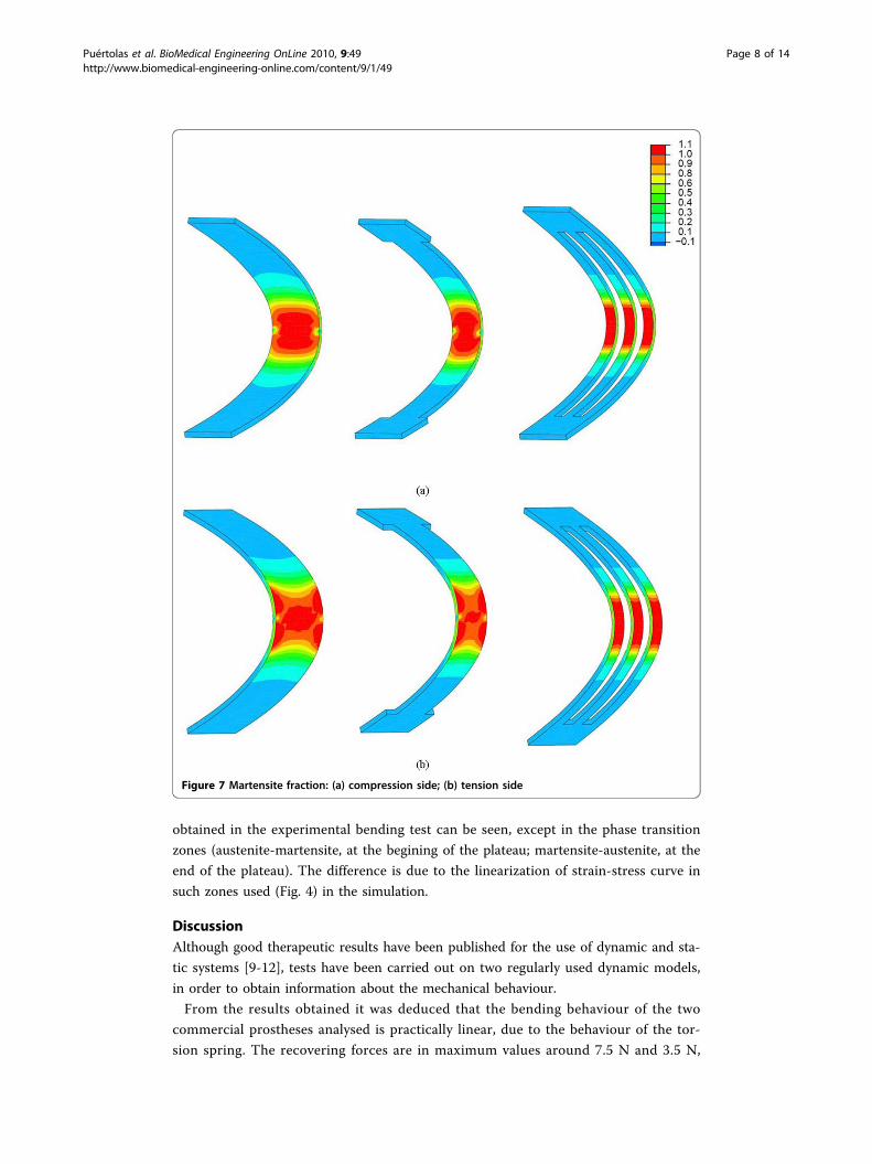
In Fig. 7 we can see the austenite-martensite transformation maps, showing the frac-
tion of martensite produced in each case, induced by the tensional level reached.
A generalized phase transformation in the central section of the plate can be seen.
This is essential in order to achieve a controlled recovering force.
Fig. 8 shows the Recovering Force-Angle curves for the different lengths and widths
of the plate, with a fixed thickness of 1 mm, while in Fig. 9 we can see the Recovering
Force-Angle curves for different lengths and thicknesses of the plate, with a fixed
width of 6 mm. In these a practically constant recovering force value can be observed
over a wide range of angles that vary between 30° and 150°. This makes it possible to
define a characteristic value of recovering force which is ascribed to an angle flexion of
80°. The same occurs in all of the cases analysed. A summary of this can be seen in
Table 2, indicating the characteristic ranks of recovering force obtained.
Finally, in order to verify the simulation results an experimental bending test was
carried out on a prototype made in accordance to the developed design, obtaining the
results shown in Fig. 10. A perfect agreement between the simulation results and those
Figure 6 Recovering force-Angle curves for commercial Bort type splints (tests)
Puértolas et al. BioMedical Engineering OnLine 2010, 9:49http://www.biomedical-engineering-online.com/content/9/1/49
Page 7 of 14
obtained in the experimental bending test can be seen, except in the phase transition
zones (austenite-martensite, at the begining of the plateau; martensite-austenite, at the
end of the plateau). The difference is due to the linearization of strain-stress curve in
such zones used (Fig. 4) in the simulation.
DiscussionAlthough good therapeutic results have been published for the use of dynamic and sta-
tic systems [9-12], tests have been carried out on two regularly used dynamic models,
in order to obtain information about the mechanical behaviour.
From the results obtained it was deduced that the bending behaviour of the two
commercial prostheses analysed is practically linear, due to the behaviour of the tor-
sion spring. The recovering forces are in maximum values around 7.5 N and 3.5 N,
Figure 7 Martensite fraction: (a) compression side; (b) tension side
Puértolas et al. BioMedical Engineering OnLine 2010, 9:49http://www.biomedical-engineering-online.com/content/9/1/49
Page 8 of 14

respectively, for an angle of 40°. These forces suffer a notable decrease as the angle
increases (recovering), reaching values that can be insufficient for the recuperation of
the joint along an angle of about 30°, and with values that are practically null from
85-90° (Fig. 6). This makes it necessary to plan a therapy in phases, with the progres-
sive substitution of splints, adjusting the rigidity in each phase. The main thing is that
the therapist has a splint at his/her disposal capable of releasing a constant and
Figure 8 Recovering force-Angle curves: (a) Length 60.0 mm, width variable, thickness 1.0 mm;(b) Length 80.0 mm, width variable, thickness 1.0 mm
Puértolas et al. BioMedical Engineering OnLine 2010, 9:49http://www.biomedical-engineering-online.com/content/9/1/49
Page 9 of 14

sufficient force which is able to correct the contracture in flexion and assure a good
final result [3].
In order to design a NiTi prosthesis with a recovering force equivalent to that of a
Bort orthosis, it is necessary to adjust the rigidity to bending to the value of this.
A parametric simulation on three alternative designs has been carried out, covering a
range of forces from 5 to 30 N, with lengths and widths capable of adapting to fingers
Figure 9 Recovering force-Angle curves: (a) Length 60.0 mm, width 6.0 mm, thickness variable;(b) Length 80.0 mm, width 6.0 mm, thickness variable
Puértolas et al. BioMedical Engineering OnLine 2010, 9:49http://www.biomedical-engineering-online.com/content/9/1/49
Page 10 of 14

of different sizes. One main advantage of the proposed designs is that they achieve a
practically constant recovering force in a range of angles from 20° to 150°. This makes
one therapeutic stage possible that practically covers the total recovery of the PIP joint.
Apart from the properties of NiTi, the biomechanical behaviour of the proposed
prosthesis compared to the commercial ones analysed is totally different due to its
design. Hence, the mechanism to transmit forces onto the finger in the Bort class of
Table 2 Splint sizes and recovering forces
Designation Length(mm)
Net width(mm)
Thickness(mm)
Characteristic Recovering Force (N)
5≤F<10 10≤F<15 15≤F<20 20≤F<25 25≤F≤30
F-80 × 6 × 0.6 80 6 0.6 7.0
F-70 × 6 × 0.6 70 6 0.6 8.0
F-40 × 6 × 0.4 40 6 0.4 7.5
F-80 × 6 × 0.8 80 6 0.8 12.5
F-80 × 4 × 1.0 80 4 1.0 14.0
F-70 × 6 × 0.8 70 6 0.8 13.8
F-60 × 6 × 0.6 60 6 0.6 10.0
F-40 × 6 × 0.5 40 6 0.5 11.5
F-80 × 5 × 1.0 80 5 1.0 18.0
F-60 × 6 × 0.8 60 6 0.8 16.5
F-40 × 6 × 0.6 40 6 0.6 16.0
F-80 × 6 × 1.0 80 6 1.0 23.0
F-60 × 4 × 1.0 60 4 1.0 20.0
F-80 × 8 × 1.0 80 8 1.0 29.0
F-70 × 6 × 1.0 70 6 1.0 28.5
F-60 × 6 × 1.0 60 6 1.0 30.0
Figure 10 Recovering force-Angle curves for the 80 × 8 × 1.0 mm splint. Experimental test versussimulation
Puértolas et al. BioMedical Engineering OnLine 2010, 9:49http://www.biomedical-engineering-online.com/content/9/1/49
Page 11 of 14

splints (and in the majority of those that exist on the market) is based on equilibrium
in a simple bending situation, with action (F1, F2) and reaction (F3) in the different
parts of the splint (Fig. 1c). On the contrary, in the developed prototype the transmis-
sion mechanism is based on equilibrium in pure bending, transmitting both torques on
the fixation rings (Fig. 3b), through the local equilibrium of forces in the fixation rings.
The common bending mechanism has two important drawbacks: firstly, for a linear
behaviour spring the ratio between recovering force and angle is constant in its whole
length. Hence, as recovery is produced the torque transmitted on the joint decreases
significantly, even though the distance from the point where the force is applied F1 on
the joint, point A in Fig. 1c becomes progressively larger. Its increase does not com-
pensate the loss of force, for which it is necessary to change the splint for another
with a different force calibration. Moreover, the forces involved in the equilibrium
have components that can generate compression or traction on the joint itself, possibly
increasing the damage to the joint.
However, in the mechanism of pure bending as it is directly transmitting torques, the
effect on the joint is always the same in all of the recovering range. In addition forces
are not generated on joints; the forces are generated at local level on the fixation rings
to give rise to the torques transmitted, acting on zones that are away from the joint
and without damaging effects. Thus the recovering moment is constant in all of the
length A1-A-A2 (Fig. 3b), without producing undesired effects on the joint. Given that
the splint reproduces in the graph moment-angle the basic behaviour of NiTi in the
tensile test, the recovering moment is practically constant in the all of the range where
the splint works. According to [4,21] a prolongated constant stress is a key factor
achieving soft tissue remodeling; our model of splint offers the advantages to adjust
the recovering force depending on the dimensions on the sheet, producing a constant
recovering force along a wide range of splinting. Then the whole treatment is possible
with only one splint, and without the need of progressive replacements as the joint
recovers.
No other splint available on the market offers this property since all of them are
based on materials and mechanisms whose global result is that of a cuasi-linear beha-
viour. This makes it impossible to obtain the curves with a practically null slope in the
recovery stage like the one presented here.
Another talking point is the optimum time for the use of straightening splints, which
Flower defined as TERT (Total End Range Time) [22], having checked that the longer
it is worn daily the better the results [22,23]. However, Flower himself concludes that
in addition to the time of use, the force application parameters are fundamental in
attaining a good correction of the deformity [23]. Due to its comfort the proposed
design makes it possible to wear permanently. On the other hand, permanent action
dynamic orthosis, regularly used in orthopaedics for the PIP joint, are difficult to fit,
above all at the level of the proximal phalange despite the therapist being able to
choose the size.
On the contrary, the designed splints in this work improve the initial adjustment and
make it easier to use for both the patient and the specialist, without presenting difficul-
ties in its fitting. The proposed design also avoids the harmful effect of pressure on the
back of the joint [3] which is produced in the usual static and dynamic systems.
Puértolas et al. BioMedical Engineering OnLine 2010, 9:49http://www.biomedical-engineering-online.com/content/9/1/49
Page 12 of 14
ConclusionsA new model of splint has been designed, simulated ant tested comparing its behaviour
with two of the most regularly used splints. The advantages offered against the most
frequently used commercial models can be summarised as:
- Better control of the recovering force.
- Maintaining the splint over long periods of time without replacement, since its
effect remains unalterable over a wide period of recuperation.
- Ease of use for both the patient and specialist.
- Ease of producing made to measure designs for each patient.
- Significant economic saving in the treatment.
For all of the above mentioned, the proposed design is highly competitive compared
to those used presently. In fact, our initial clinical trials have confirmed the biomecha-
nical advantages of the proposed design.
AcknowledgementsThis work has been realised in the frame of the research project FIS-PI-031287 (Health Research Found - SpanishGovernment).
Author details1Department of Mechanical Engineering, University of Zaragoza, María de Luna 3, 50018 Zaragoza, Spain. 2Departmentof Surgery, University of Zaragoza, Domingo Miral s/n, 50009 Zaragoza, Spain. 3Department of Orthopaedic Surgeryand Traumatology, Miguel Servet University Hospital, Paseo Isabel la Católica 1, 50009 Zaragoza, Spain. 4Aragon HealthSciences Institute, Avenida Gómez Laguna, 25, 50009 Zaragoza, Spain. 5Department of Science and Technology ofMaterials, University of Zaragoza, María de Luna 3, 50018 Zaragoza, Spain.
Authors’ contributionsJPG and AH carried out the design of the splint. SP, LG and EI carried out the finite element simulations. JC and JPcarried out the experimental tests. All authors were involved in the study design and writing of the manuscript. Allauthors read and approved the final version of the manuscript.
Competing interestsThe authors declare that they have no competing interests.
Received: 7 June 2010 Accepted: 13 September 2010 Published: 13 September 2010
References1. Prosser R: Splinting in the management of proximal interphalangeal joint flexion contracture. Jour Hand Therapy
1996, 9:378-386.2. Wilton J: Hand splinting: Principles of design and fabrication.Edited by: Saunders WB. London; 1997:.3. Li C: Force analysis of the Belly Gutter and Capener splints. Jour Hand Therapy 1999, 12:337-343.4. Fess EE, McCollum M: The influence of splinting on healing tissues. Jour Hand Therapy 1998, 11:157-161.5. Wu SH: A belly gunter splint for proximal interphalangeal joint flexion contracture. Amer Jour Occup Therapy 1990,
45:939-943.6. Fess EE: Force magnitude of commercial spring-coil and sring-wire splint designed to extend the proximal
interphalangeal joint. Jour Hand Therapy 1988, 1:86-90.7. Sheehan JL, Winzeler-Mercay U, Mudie MH: A randomized controlled pilot study to obtain the best estimate of the
size of the effect of a termoplastic resting splint on spasticity in the stroke-affected wrist and fingers. ClinRehabilitation 2006, 20(12):1032-1037.
8. Punsola-Izard V, Rouzaud JC, Thomas D, García-Elías L: Le collage en tension dans les orthèses dynamiques enmatériau neoprene. Chirugie de la Main 2001, 20:231-235.
9. Benaglia PG, Sartorio F, Franchignoni F: A new thermoplastic splint for proximal interphalangeal joint flexioncontractures. Jour Sports Med Phys Fitness 1999, 39:249-252.
10. Li-Tsang CWP, Hung LK, Mask AFT: The effect of corrective splinting on flexion contracture of rheumatoid fingers.Jour Hand Therapy 2002, 15:185-191.
11. Glasgow C, Wilton J, Tooth L: Optimal daily total end range time for contracture: resolution in hand splinting. JourHand Therapy 2003, 16(3):207-218.
12. Schwartz DA, Janssen RG: Static progressive splint for composite flexion. Jour Hand Therapy 2005, 18:447-449.13. Petrini L, Migliavacca F, Massarotti P, Schievano S, Dubini G, Auricchio F: Computational studies of shape memory
alloy behavior in biomedical applications. Jour Biomech Eng 2005, 127(4):716-725.
Puértolas et al. BioMedical Engineering OnLine 2010, 9:49http://www.biomedical-engineering-online.com/content/9/1/49
Page 13 of 14

14. Puértolas JA, Pérez-García JM, Juan E, Rios R: Design of a suture anchor based on the superelasticity of the Ni-Tialloy. Biomed Mater Eng 2002, 12(3):283-289.
15. Lahoz R, Gracia L, Puértolas JA: Training of the two-way shape memory eggect by bending in NiTi alloys. Jour EngMater And Technology 2002, 124(4):397-401.
16. Domingo S, Puértolas S, Gracia L, Mainar M, Usón J, Puértolas JA: Design, manufacture and evaluation of a NiTi stentfor colon obstruction. Bio-Med Mater Eng 2005, 15(5):357-365.
17. Domingo S, Puértolas S, Gracia L, Puértolas JA: Mechanical comparative analysis of stents for colorectal obstruction,”Min. Invas Ther And Allied Technologies 2006, 15(6):331-338.
18. Buehler WJ, Wiley RL: Nickel-base alloys 1965, U.S. Patent 3.174.851.19. Auricchio F, Petrini L: Improvements and algorithmical considerations on a recent three-dimensional model
describing stress-induced solid phase transformations. Int Jour Num Methods in Engineering 2002, 55:1255-1284.20. ABAQUS: 2009 [http://www.simulia.com/].21. Fess EE: A history of splinting: To understand the presen, view the past. Jour Hand Therapy 2002, 15:97-132.22. Flower KR, LaStayo P: Effect of total end range time on improving passive range of motion. Jour Hand Therapy 1994,
7:150-157.23. Flower KR: A proposed decision hierarchy for splinting the stiff joint, with an emphasis on force application
parameters. Jour Hand Therapy 2002, 15:158-162.
doi:10.1186/1475-925X-9-49Cite this article as: Puértolas et al.: Design of splints based on the NiTi alloy for the correction of jointdeformities in the fingers. BioMedical Engineering OnLine 2010 9:49.
Submit your next manuscript to BioMed Centraland take full advantage of:
• Convenient online submission
• Thorough peer review
• No space constraints or color figure charges
• Immediate publication on acceptance
• Inclusion in PubMed, CAS, Scopus and Google Scholar
• Research which is freely available for redistribution
Submit your manuscript at www.biomedcentral.com/submit
Puértolas et al. BioMedical Engineering OnLine 2010, 9:49http://www.biomedical-engineering-online.com/content/9/1/49
Page 14 of 14