study of an open circuit hydraulic power system...
TRANSCRIPT
STUDY OF AN OPEN CIRCUIT HYDRAULIC POWER SYSTEM
WITH COMPACT COOLER-RESERVOIR UNIT
By
Ibrahim Subhi Al-Natour
B.Eng., M.Eng.
This thesis is submitted as the fulfilment of the requirement for the award of
Doctor of philosophy to:
DUBLIN CITY UNIVERSITY
Sponsoring Establishment:
Scientific Studies and Research Centre
DAMASCUS-SYRIA
DECEMBER 1992

To
My Parents
Wife Kinaz
Daughters Inas, Nuha, Dana
DECLARATION
I herby certify that this material, which I now submit for assessment on the
programme of study leading to the award of Doctor of philosophy is entirely my
own work and has not been taken from the work of others save and to extend that
such work has been cited and acknowledged within the text of my work.
SIGNED---------------------------------------------- Date: December 1992
IBRAHIM SUBHI AL NATOUR

CONTENTS PAGE
DECLARATION i
CONTENTS ii
ABSTRACT vii
ACKNOWLEDGEMENT viii
INDEX TO FIGURES ix
INDEX TO PLATES xxiv
NOMENCLATURES xxx
CHAPTER ^INTRODUCTION 1
1.1. INTRODUCTION 1
1.2. CIRCUIT CLASSIFICATION 2
1.2.1. OPEN HYDRAULIC CIRCUIT 2
1.2.2. CLOSED HYDRAULIC CIRCUIT 3
1.3. HEAT GENERATION IN HYDRAULIC SYSTEM 4
1.4. BACKGROUND LITERATURE OF TEMPERATURE 6
ANALYSIS IN HYDRAULIC SYSTEMS
1.5. BACKGROUND LITERATURE OF A DIGITAL 8
SIMULATION IN HYDRAULIC SYSTEMS
1.6. NEED FOR IMPROVING PERFORMANCE OF I I
HYDRAULIC SYSTEM

CONTENTS PAGE
1.7. THE PRESENT RESEARCH AND ITS OBJECTIVES 13
CHAPTER 2: DESIGN AND COMMISSION OF 23
THE EXPERIMENTAL EQUIPMENT
2.1. INTRODUCTION 23
2.2. EXPERIMENTAL TEST RIG COMPONENTS 23
2.3. INSTRUMENTATION OF THE EXPERIMENTAL 25
TEST RIG
2.3.1. HYDRAULIC PUMP 25
2.3.2. HYDRAULIC MOTOR 26
2.3.3. VALVES 26
2.3.4. PIPELINES 27
2.3.5. RESERVOIR 28
2.3.6. COOLER 28
2.4. INSTRUMENTATION AND MEASURING 29
EQUIPMENT
2.5. EXPERIMENTAL TEST RIG LAYOUT 31
CHAPTER 3: MATHEMATICAL MODEL AND
SIMULATION
3.1. INTRODUCTION
64
64
CONTENTS PAGE
3.2. THE PRESENT ANALYSIS 64
3.3. CLOSED AND OPEN THERMAL SYSTEMS 67
3.4. THE FIRST LAW FOR OPEN SYSTEMS 67
3.5. FLUID TEMPERATURE IN A PIPE SECTION 73
OF A HYDRAULIC SYSTEMS
3.6. HEAT TRANSFER THROUGH A PIPE WALL IN 77
HYDRAULIC SYSTEMS
3.6.1. FORCED CONVECTION 79
3.6.2. CONDUCTION AND NATURAL CONVECTION 81
AND RADIATION
3.7. PIPE WALL TEMPERATURE IN HYDRAULIC 83
SYSTEMS
3.8. A MATHEMATICAL MODEL FOR TEMPERATURE 88
ANALYSIS IN AN OPEN HYDRAULIC SYSTEMS
3.9. AN ANALYTICAL MODEL FOR TEMPERATURE 89
OF RESERVOIR IN HYDRAULIC SYSTEMS
3.10. THE CALCULATION OF POWER LOSSES 95
IN HYDRAULIC SYSTEMS
3.11. NUMERICAL TECHNIQUE FOR TEMPERATURE 100
CALCULATION IN HYDRAULIC SYSTEM

CONTENTS PAGE
3.12. COMPUTER AIDED DESIGN AND SIMULATION 102
OF FLUID POWER SYSTEMS
3.12.1. SIMULATION DIAGRAM 104
3.12.2. DATA ACQUISITION FOR SIMULATION 105
3.12.3. SIMULATION RESULTS AND DISCUSSION 107
3.13. TEMPERATURE SIMULATIONS RESULTS FOR 113
THE RESERVOIR IN THE OPEN HYDRAULIC
DRIVE MIXER SYSTEM
CHAPTER 4: EXPERIMENTAL INVESTIGATION 197
AND RESULTS
4.1. EXPERIMENTAL PROCEDURE 197
4.2. EXPERIMENTAL RESULTS 198
CHAPTER 5: DISCUSSION ON THE THEORETICAL 235
AND EXPERIMENTAL RESULTS
5.1.1. DISCUSSION ON THE PROCEDURE AND
EXPERIMENTAL RESULTS
5.1.2. DISCUSSION ON THE ANALYSIS,
235
240

SIMULATION PACKAGE AND THE THEORETICAL RESULTS
5.2. COMPARATIVE PERFORMANCE OF THE 243
HYDRAULIC SYSTEMS
CONTENTS PAGE
CHAPTER 6: CONCLUSION AND SUGGESTION FOR 251
FUTURE WORK
6.1. CONCLUSION 251
6.2. SUGGESTION FOR FUTURE WORK 253
6.2.1. THEORETICALLY 254
6.2.2 EXPERIMENTALLY 255
REFERENCES 256
APPENDICES
vi

ABSTRACT
Study of an Open Circuit Hydraulic Power System
with Compact Cooler-Reservoir Unit
IBRAHIM SUBITI AL NATOIJR BEng, MEng.
In this research, a complete open hydraulic drive mixer system has been designed, instrumented and commissioned, and an extensive programme of experimental tests has been undertaken to 1)- investigate the effectiveness of a cooling unit as an integral part of the open hydraulic system and 2)- validate the mathematical model. The results have shown that the working temperature could be reduced by 40 % by using the integral cooling/reservoir unit and the temperature is always kept below the recommended operation temperature.
A mathematical model for temperature distribution under unsteady state conditions in an open hydraulic systems has been developed to predict pipe wall and fluid temperatures in the system. The thermodynamics processes and heat transfer by convection, conduction and radiation have been taken into account. The developed temperature transient equations are solved by using numerical integration technique which are used widely in computer programming.
A software package has been developed to be used in hydraulic system design. The main advantage of this package is the user friendliness. The simulation results shows a significant difference between the temperatures of the fluid and the pipe wall in the hydraulic systems and demonstrated that this mathematical model is more accurate than those reported elsewhere.
The main results of this investigation is that the hydraulic reservoir has been reduced in the size to about 15 percent of the conventional reservoir in the open hydraulic systems. Furthermore, the experimental results have shown a close agreement with the theoretical results.
ACKNOWLEDGEMENTS
The author wishes to express his gratitude and sincere thanks to professor
M.S .J.HASHMI, Head of school of mechanical and manufacturing engineering for
his support and helpful supervision and guidance during the course of this work.
Thanks are also due to Mr. T. Walsh and his staff for their support at various
stages of this work.
The author acknowledges the support and assistance given by the scientific studies
and research centre in DAMASCUS, SYRIA for providing financial support
towards this research.
Last but not least, the support and encouragement of my wife and family deserve
greater acknowledgements than words can express

LIST OF FIGURES
Fig. No. Page
1 A simple hydraulic system 16
2 An example of a typical open hydraulic system 17
3 An example of a typical closed hydraulic circuit 18
4 A closed loop hydraulic transmission with 19
make-up pump
5 The effects of hot oil on hydraulic system 20
performance
6 An application of an open simulated hydraulic 21
system used for lowering and raising the nose
wheel of an aircraft landing gear
7 An application of a closed hydraulic 22
transmission system to an undersea
submarine research vehicle
8 An open hydraulic drive mixer test rig 34
9 External hydraulic gear pump 35
10 The cartridge insert relief valve 36
11 Valve block assembly 37
12 Structure of a single flexible wire braid 38
ix

LIST OF FIGURES
hydraulic hose
13 Structure of the hydraulic reservoir 39
14 Position of the measurements equipment 40
15 Pressure gauge 41
16 Flowrate and temperature meter 42
17 Mounting detail of the unit 43
18 The pump with front mounting 44
flange and bracket
19 Position of drain, pump and hydraulic 45
motor port in the control block
20 The location of the mixer inside the 46
container
21 Open thermal system undergoing an imaginary 153
non-flow process
22 The flow of a closed system (the shaded area) 154
Fig. No. Page
through the space occupied by an open system,
and the conversion of the first-law statement
for closed systems into a statement valid for
open system.
x

LIST OF FIGURES
23 Open thermal system of fluid in a pipe section 155
24 Heat flow losses through the hose in surroundings 156
25 Heat flow through a hydraulic hose 157
26 A hydraulic reservoir regarded as an open thermal 158
system
27 Viscosity for a number of hydraulic oil SHELL 159
TELLUS used in this research
28 Friction factor Vs. Reynolds number for turbulent flow. 160
29 K- values for several valves and fittings 161
30 Block diagram for the dynamic and thermal simulation of
the open hydraulic systems using the developed programme 162
31 The effects of power loss on the fluid temperature in the 163
open hydraulic drive mixer system
32 The effects of power loss on the outside hose wall 164
temperature in the open hydraulic drive mixer system
33 The effects of pipelength on the fluid temperature 165
distribution in the open hydraulic drive mixer system
34 The effects of pipelength on the outside hose wall 166
temperature variation in the open hydraulic drive
Fig. No. Page
xi

LIST OF FIGURES
mixer system
35 The effects of internal diameter of hose on the fluid 167
temperature variation in the open hydraulic drive mixer system
36 The effects of internal diameter of hose on the 168
outside hose wall temperature variation in the
open hydraulic drive mixer system
37 The effects of external hose diameter on the outside 169
hose wall temperature variation in the open hydraulic
drive mixer system
38 Simulated results of the effects of external hose 170
diameter on fluid temperature variation in the
open drive mixer system
39 The effects of conductivity of pipe material on the 171
outside hose wall temperature variation in the
open hydraulic drive mixer system
40 The effects of conductivity of pipe wall material 172
on fluid temperature variation in the open
hydraulic drive mixer system
Fig. No Page
xii

LIST OF FIGURE
41 The effects of specific heat of pipe material on
the outside hose wall temperature variation
in the open hydraulic drive mixer system
42 The effects of specific heat of pipe material on
fluid temperature variation in the open hydraulic
drive mixer system
43 The effects of density of pipe material on the outside
hose wall temperature variation in the open hydraulic
drive mixer system
44 Simulated results of the effects of density of pipe
material on fluid temperature variation in the
open hydraulic drive mixer system
45 The effects of emissivity of pipe material on the
outside hose wall temperature variation in the
open hydraulic drive mixer system
46 The effects of emissivity of pipe material on
fluid temperature variation in the open
hydraulic drive mixer system
Fig. No.
xiii
173
174
175
176
177
178
Page
Fig. No
LIST OF FIGURES
Page
47 Simulated results of the effects of type of pipe 179
material on outside pipe wall temperature in the
open hydraulic drive mixer system
48 Simulated results of the effects of type of pipe 180
material on fluid temperature variation in the
open hydraulic drive mixer system
49 Comparison of the effects of radiation on the fluid 181
temperature in the open hydraulic drive mixer system
50 Comparison of the effects of the radiation on the 182
outside hose wall temperature in the open hydraulic
drive mixer system
51 The effects of fluid height in the reservoir on 183
fluid temperature variation in the open hydraulic
drive mixer system
52 The effects of fluid height in the reservoir on the 184
outside hose wall temperature variation in the
open hydraulic drive mixer system
53 The effects of length of the base of the reservoir 185
on fluid temperature variation in the open
xiv

Fig. No.
LIST OF FIGURES
Page
hydraulic drive mixer system
54 The effects of the length of the base of the 186
reservoir on the outside hose wall temperature
variation the open hydraulic drive mixer system
55 The effects of the width of the base of the reservoir 187
on fluid temperature variation in the open
hydraulic drive mixer system
56 The effects of the width of the base of the reservoir 188
on the outside hose wall temperature in the open
hydraulic drive mixer system
57 The effects of thickness of the wall of the reservoir 189
on the fluid temperature variation in the open
hydraulic drive mixer system
58 The effects of the thickness of the wall of the 190
reservoir on the outside hose wall temperature
in the open hydraulic drive mixer system
59 The effects of material of the reservoir on the 191
fluid temperature variation in the open
xv

IJST OF FIGURES
hydraulic drive mixer system
60 The effects of material of the reservoir on the 192
outside hose wall temperature variation in
the open hydraulic drive mixer system
61 Simulated results of the effects of exchange 193
flow rate between loop and reservoir on loop
fluid temperature in the open hydraulic drive
mixer system
62 Comparison of simulated results of loop and 194
reservoir fluid temperature in the open
hydraulic drive mixer system
63 Comparison of simulated results of loop and 195
reservoir fluid temperature with consideration of heat
transfer by radiation in the open hydraulic
drive mixer system.
64 Comparison of simulated loop and reservoir fluid 196
temperatures with a big increase of the system
power loss in the open hydraulic drive mixer system
Fig. No. Page
xvi

LIST OF FIGURES
Experimental results of temperature variation
of the outside hose wall of the hydraulic motor
for flow rate of 30 1/min in the open hydraulic
drive mixer system
Experimental results of temperature variation
of the outside hose wall of the hydraulic motor
for flow rate of 25 1/min in the open hydraulic
drive mixer system
Experimental results of temperature variation
of the outside hose wall of the return line of the
hydraulic motor at flow rate of 20 1/min in the
open hydraulic drive mixer system
Experimental results of temperature variation
of the outside hose wall of the hydraulic motor
for flow rate of 10 1/min in the open hydraulic
drive mixer system
Experimental results of temperature variation
of the outside hose wall of the hydraulic motor
for flow rate of 5 1/min in the open hydraulic

LIST OF FIGURES
drive mixer system
Experimental results of temperature variation
of the outside hose wall of the hydraulic pump
for flow rate of 30 1/min. in the open hydraulic
drive mixer system
Experimental Results of temperature variation
of the outside hose wall of the hydraulic pump
for flow rate of 25 1/min in the open hydraulic
drive mixer system
Experimental results of the temperature variation
of the outside hose wall of the hydraulic pump
for flow rate of 20 1/min in the open hydraulic
drive mixer system
Experimental results of temperature variation
of the outside hose wall of the hydraulic pump
for flow rate of 10 1/min in the open hydraulic
drive mixer system
Experimental results of temperature variation
of the outside hose wall of the hydraulic pump
xviii
LIST OF FIGURES
for flow rate of 5 1/min in the open hydraulic
drive mixer system
Experimental results of temperature variation
of fluid for flow rate of 30 1/min in the open
hydraulic drive mixer system
Experimental results of temperature variation
of fluid for flow rate of 25 1/min in the open
hydraulic drive mixer system
Experimental results of temperature variation
of fluid for flow rate of 20 1/min in the open
hydraulic drive mixer system
Experimental results of temperature variation
of fluid for flow rate of 10 1/min in the open
hydraulic drive mixer system
Experimental results of the effects of flow rate
on the outside hose wall temperature variation
of the return line in the open hydraulic drive
mixer system
Experimental results of the effects of flow rate
Fig. No.
81
82
83
84
85
LIST OF FIGURES
Page
on the outside hose wall temperature variation
of the pressure line in the open hydraulic drive
mixer system
Experimental results of the effects of flow rate 221
on fluid temperature variation of the return
line in the open hydraulic drive mixer system
Experimental results of the effects of flow rate 222
on fluid temperature variation of the pressure
line in the open hydraulic drive mixer system
Experimental results of the comparison of hose 223
wall temperature between pressure and return lines
in the open hydraulic drive mixer system
Experimental results of fluid temperature variation 224
in the open hydraulic drive mixer system
Experimental results of comparison of hose wall 225
temperature in the high pressure line of the open
hydraulic drive mixer system
Experimental results of the comparison of fluid and 226
hose wall temperature at return line in the open
xx

LIST OF FIGURES
hydraulic drive mixer system
Experimental results of the comparison of fluid and
hose wall temperature at high pressure pipe line
in the open hydraulic drive mixer system
Experimental results of hoses wall temperature
variation in the open hydraulic drive mixer
system
Experimental results of comparison of fluid
temperature in the pressure line before and after
cooler in the open hydraulic drive mixer system
Experimental results of comparison of fluid
temperature in the return line before and after
cooler in the open hydraulic drive mixer system
Experimental results of comparison of fluid
temperature between the return line and the
pressure line before and after the cooler in the
open hydraulic drive mixer system
Experimental results of the effects of fan speed
in the cooling unit on performance of the open
LIST OF FIGURES
hydraulic drive mixer system
93 Experimental results of the effects of flow rate 233
on fan speed in the cooling unit in the open
hydraulic drive mixer system
94 Experimental results of the effects of flow rate 234
on working pressure in the open hydraulic drive
mixer system
95 Comparison between fluid and pipe wall temperature 246
in the open hydraulic drive mixer system
96 Comparison between experimental and theoretical 247
results of fluid temperature in the pressure line
in the open hydraulic rive mixer system
97 Comparison between experimental and theoretical 248
results of hose wall temperature in the pressure
line in the open hydraulic drive mixer system
98 Comparison of the fluid temperature between the 249
present analysis and the analysis in Reference (15)
in the open hydraulic drive mixer system
99 Comparison of the outside wall temperature of the 250
Fig. No. Pag
xxii

hose between the present analysis and the
analysis in Reference (15)
xxiii

LIST OF PLATES
Plate No.
Page
1 General view of the open hydraulic drive mixer system 55
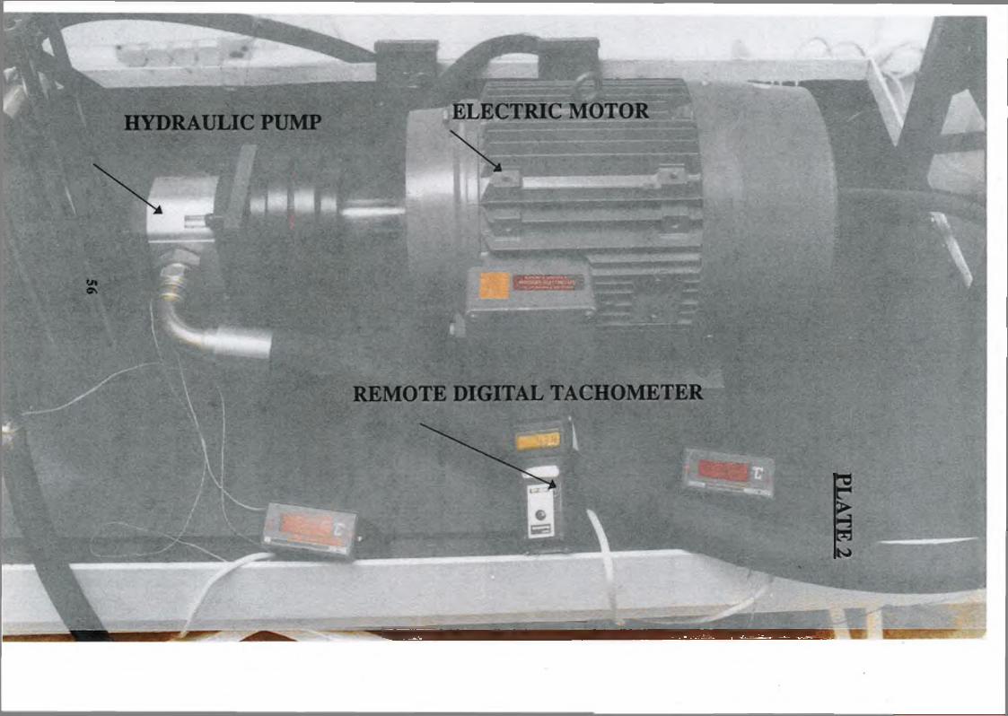
2 Hydraulic pump, electric motor and remote digital tachometer 56
3 Hydraulic motor, solenoid directional control valve, 57
container pressure line, suction line and return line
4 Cooling unit, fluid level gauge and hydraulic reservoir 58
5 Radiator 59
6 Thermocouple with digital output 60
7 Inline temperature and flow rate meters, pressure gauge and 61
quick-disconnect hose couplings
8 Valves control block, motor drain line, relief valve and 62
system control valve
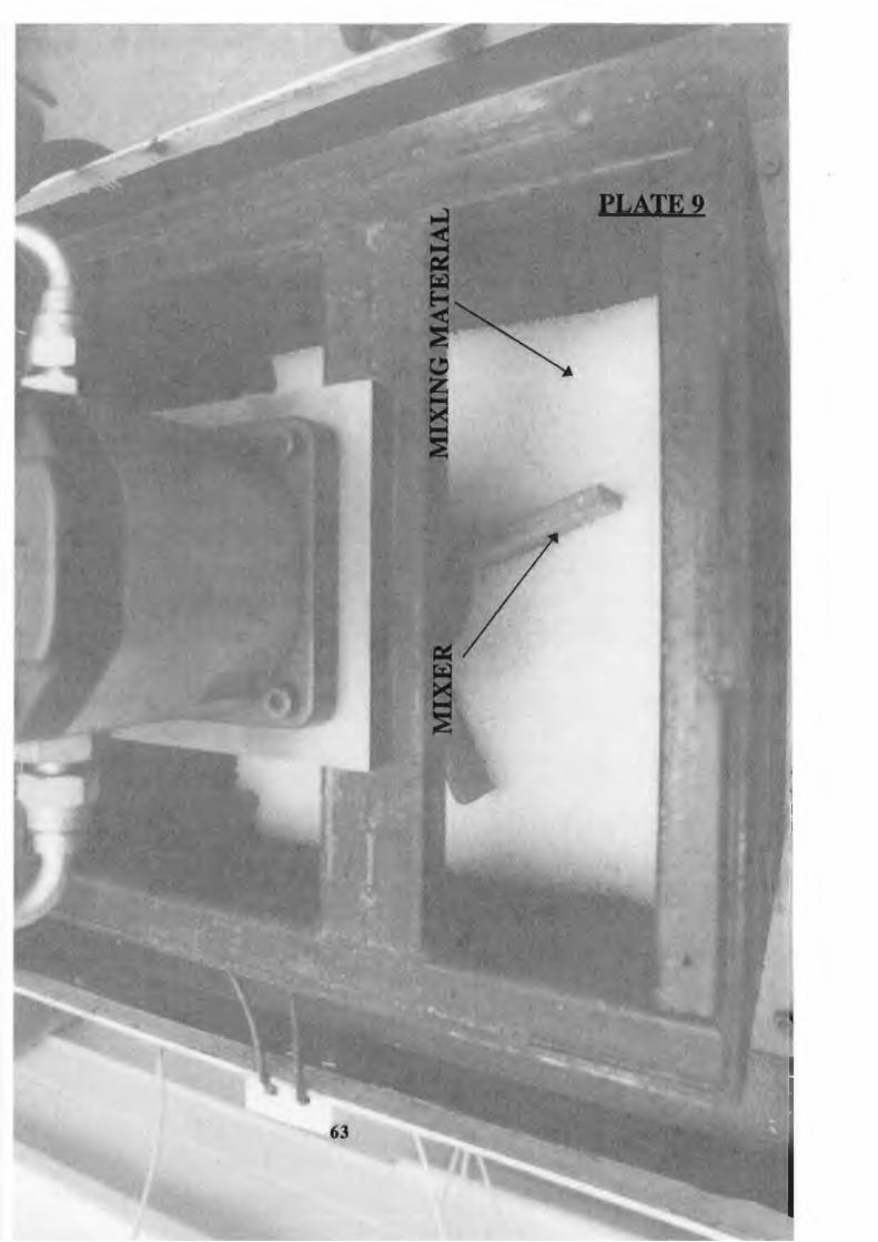
9 Mixer and mixing material 63
xxiv

LIST OF TABLES
Table No. Page
1 Technical data for hydraulic pump 47
2 Technical data for hydraulic motor 47
3 Technical data for pressure relief valve 48
4 Technical data for check valve 48
5 Technical data for flow control valve 49
6 Technical data for directional control valve 49
7 Technical data for electric motor 50
8 Technical data for pressure pipe line 50
9 Technical data for pressure return line 51
10 Technical data for pressure suction line 51
11 Technical data for hydraulic reservoir 52
12 Technical data for hydraulic oil cooler 52
13 Technical data for mixer 53
14 Technical data for experimental test rig 54
15 Normal emissivity for several used material in
hydraulics system
119
16 Simplified Equations for free convection heat
transfer coefficients in air at atmospheric pressure
120
17 Specific heat for several used material in hydraulic
XXV
121

18
19
20
21
22
23
24
25
26
27
28
Table No.
LIST OF TABLES
Page
systems
Thermal conductivity for several used materials 122
in hydraulic systems
Absolute roughness of commercially pipe and tubing 123
Density for several used materials in hydraulic 124
systems
Parametric data used in simulation for fluid 125
properties
Parametric data used in simulation for the electric 126
motor
Parametric data used in simulation for hydraulic pump 127
Parametric data used in simulation for hydraulic motor 128
Parametric data used in simulation for high pressure 129
pipeline before directional control valve
Parametric data used in simulation for high pressure 130
pipeline after directional control valve
Parametric data used in simulation for pressure 131
relief valve
Parametric data used in simulation for flow control 132
xxvi

Table No.
29
30
31
32
33
34
35
36
valve
Parametric data used in simulation for check valve 133
Parametric data used in simulation for directional 134
control valve
Parametric data used in simulation for pressure 135
return line
Parametric data used in simulation for pressure 136
suction line
Parametric data used in simulation for mixer 137
Parametric data used in simulation for temperature 138
and fluid property calculation in the open hydraulic
drive mixer system with hydraulic hoses
Parametric data used in simulation for temperature 139
and fluid property calculation in the open hydraulic
drive mixer system with copper pipes
Parametric data used in simulation for temperature 140
and fluid property calculation in the open hydraulic
drive mixer system with steel pipes
LIST OF TABLES
Page
xxvii

LIST OF TABLES
Parametric data used in simulation for the single
wired hydraulic hose in the high pressure pipeline
before the directional control valve
Parametric data used in simulation for the single
wired hydraulic hose in the high pressure pipeline
after directional control valve
Parametric data used in simulation for the single
wired hydraulic hose at the inlet of the hydraulic
motor
Parametric data used in simulation for the single
wired hydraulic hose in the return line before
the directional control valve
Parametric data used in simulation for the single
wired hydraulic hose in the suction line
Parametric data used in simulation for fluid
temperature and property calculation in the open
hydraulic drive mixer system using the developed
mathematical model
Parametric data used in simulation for the fluid
xxviii

LIST OF TABLES
Table No. Page
temperature calculation in the reservoir of the
open hydraulic drive mixer system
44 Parametric data used in simulation for the fluid 148
temperature and property model in the first part
of the high pressure line
45 Parametric data used in simulation for the fluid 149
temperature and property model in the second part
of the high pressure line
46 Parametric data used in simulation for the fluid 150
temperature and property model in the return line
47 Parametric data used in simulation for the fluid 151
temperature and property model in the suction line
xxix

Nomenclature
A! inside surface area of hose [m2]
A2 outside surface area of hose [m2]
Alhr reservoir base area [m2]
A2vr one side of fluid vertical area in the reservoir [m2]
A3vr another side of fluid vertical area in the reservoir [m2]
Am logarithmic mean surface area of hose [m2]
Cpf specific heat of fluid [J/(kg.K)]
Cph specific heat of hose wall [J/(kg.K]
D hose diameter [m]
f dimensionless friction factor
g acceleration of gravity [m/s2]
ha coefficient of heat transfer by natural convection [W/(m2.K)]
Hf, Hff head loss [m]
k thermal conductivity of hose wall material [W/(m.K)]
thermal conductivity of reservoir wall material [W/(m.K)]
K constant
L length of hose [m]
nij mass flowrate of fluid into reservoir [kg/s.]
m2 mass flowrate of fluid outlet of reservoir [kg/s]
Mf mass of fluid in the system [kg]

Mfl, mass of fluid within the hos section [kg]
MP mass of wall hose material [kg]
AP pressure drop [bar (105 N/m2)]
Q flowrate [m3/s]
Q, heat flow transferred from fluid to hose wall by forced convection [W/(m.K)]
Q2 heat flow transferred from hose wall to surrounding atmosphere [W/(m.K)]
Q1R heat flow transferred from fluid into its surrounding atmosphere at vertical wall
of reservoir [W/(m.K)]
Q2R heat flow transferred from fluid into its surrounding atmosphere at horizontal
wall of reservoir [W/(m.K)]
Q3R heat flow transferred from the surface of fluid in the reservoir to atmosphere
[W/(m.K)]
R, ,R2 hose inside and outside radius [m]
S thickness of wall of reservoir [m]
Tj temperature of the wall at inside hose surface [K]
T2 temperature of the wall at outside hose wall surface [K]
Ta constant surrounding atmosphere temperature [K]
Tf temperature of fluid [K]
T^, temperature of fluid in reservoir [K]
Twrb outside wall temperature at bottom of reservoir [K]
Twrv outside vertical wall temperature of reservoir [K]
W power losses converted into heat energy [Watts]

Greek symbols
e emissivity
v kinematic viscosity [m2 /s]
o surface tension [N/m]

CHAPTER: 1
INTRODUCTION
1.1 power hydraulics means using pressurized fluid in aconfined system to accomplish work. Most hydraulic systems use petroleum oil, but often synthetic oil and water based fluid are used for safety reasons. A fluid power system accomplishes two main objectives. First, it provides substantial fluid force to move actuators in locations away from the power source where the two are connected by pipes, tubes, or hoses.
A power source, primarily, is an electric motor or diesel engine coupled to a hydraulic pump, which can be housed in one area to power a cylinder or hydraulic motor at a distance location. Secondly, fluid power systems accomplish highly accurate and precise movement of the actuator with relative ease, this is particularly important in such applications as in the machine tool industry where tolerances are often specified to one ten thousandth of mm and must be repeatable during several million cycles.
Industrial fluid power is a relatively young field of energy transmission and control. Modern hydraulic

equipment can economically convert mechanical energy into fluid energy, and with simple components this energy may be regulated to provide direction, speed, and force control. No other type of power transmission provides the range of control of force, speed, and direction that is possible with fluid power transmission Many hydraulic systems seem exceedingly complex, however, their basic design is quite simple. Regardless of the complexity or simplicity of a hydraulic system, each system contains several basic components: (1) areservoir to hold the fluid supply, (2) connecting lines to transmit the fluid power, (3) a pump to convert input power into fluid power, (4) a pressure control valve to regulate pressure, (5) a directional control valve to control the direction of fluid flow, (6) a flow control device to regulate speed or fluid flow, and (7) an actuator to convert hydraulic power into mechanical motion. Fig.(1) shows a simple hydraulic system which explains the above arrangement.
1.2. Circuit Classification: Any hydraulic system can be
classified as open or closed circuits.
1.2.1 Open hydraulic circuit: In an open hydraulic circuit
fixed displacement pumps are used. An open hydraulic circuit contains a pump or pumps supplied with liquid

from a reservoir, usually at atmospheric pressure. The reservoir can be sealed and pressurized to minimize entry of foreign matter or to assist movement of fluid into the pump inlet. The discharge of the pump is directed through appropriate valves to the hydraulic cylinder or motor, thereby providing the desired linear or rotary force and motion, the returned fluid directed to the reservoir.
Ideally, a large reservoir is used in a conventional open circuit to allow air bubbles and foam to escape from the fluid and to assure that during peak pump demands the oil level will not drop below the suction line. The full flow demand of the pump is supplied through a suction pipeline which has to be of a large diameter in order to prevent cavitation at the pump inlet. The fluid reservoir also acts as a heat dissipator during periods of high heat generation in the system. Fig.(2) shows an example of a typical open hydraulic system.
1.2.2 Closed hydraulic circuit: The key element of the open
hydraulic system is the reservoir of significant size where the spent fluid is returned prior to recycling through the pump. A closed hydraulic circuit usually consists of one variable displacement pump which can pump liguid in and out of each port according to the position of the control element and one hydraulic motor
whose inlet and outlet ports are connected to the two ports of the pump. Fig. (3) shows an example of a closed circuit. There is always some designed hydrostatic transmission in a closed-loop configuration, therefore, a separate fluid supply has to be provided to make up the leakage, this is usually achieved by using a make-up pump to feed the low pressure side of the loop as shown if Fig. (4)
1.3 Heat Generation in a Hydraulic System: in any hydraulic
system it is desirable to maintain the fluid temperature at, or preferably below the recommended or specified maximum working temperature for continuous duty.
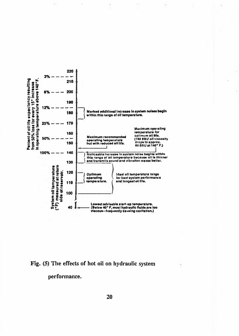
A hydraulic system that is allowed to overheat can cause costly seal deterioration and fluid oxidation or breakdown. This results in corrosion and formation of sludge and varnish, which may in turn clog orifices and accelerate valve wear and tear. In some cases, extreme temperatures will cause seizure of valves, pumps, and other components. In addition, oil viscosity will decrease and system operation will probably become erratic. However, it is acknowledged that the ideal operational temperature of industrial oil hydraulic system should not exceed 65 °C, but the recommendedmaximum operating temperature is below 50 °C because above that level the life of most fluids is shortened.
4

Fig (5) according to Ref (1) shows the effects of hot oil on system performance.
To design a hydraulic system that will maintain thermal stability, it is necessary to understand how hydraulic systems generate and dissipate heat. Heat is generated in hydraulic system wherever oil flows from higher to lower pressure without doing mechanical work. This means that if a relief valve, for example, is allowing the oil to flow back to the reservoir, and the system pressure is being maintained, the difference in pressure or loss is the difference between the system pressure and the reservoir line pressure.
5

1.4 Background Literature of Temperature Analysis in Hydrau
lic Systems: Thermal transients in a hydraulic system are
a fundamental aspect of system performance and generally are concerned with thermodynamic processes which are associated with the power losses converted into heat and also, associated with heat flow transfer and losses during the system operation. Initial studies (2) of temperature analysis in hydraulic systems were carried out on a hydrostatic winch drive where the temperature effects were considered to be vitally important. A cooler had been installed in this system and its thermal characteristics were taken into account, but for simplicity the heat transfer between the fluid and the pipe wall was ignored. However, most conventional studies for temperature change in the hydraulic systems deal with steady state conditions like those given in references (3) to (9) in which heat flows continuously at a uniform rate and unsteady processes were ignored due to their complexities. The transient temperatures in the hydraulic systems have been studied by Ezekiel and Paynter (10) and by those given in Refs. (11) to (14). However, these researchers did not consider heat transfer effects even those associated with coolers.
The following assumptions were usually made in these previous studies:
6

(1) the system inside and outside pipe wall temperatures are the same as the fluid temperature, and (2) the heat generated by the pressure losses due to pipe friction was negligible . Yang (15,16), Yang and Bowns (17) and Yang (18) have studied the temperature analysis in hydraulic system and they considered the hydraulic system as a closed thermal system and they obtained their experimental results using a closed or partially closed hydrostatic drive propeller system. However, in their study, the heat transfer by conduction along the pipes and reservoir in the system and heat transfer by radiation from the surfaces of reservoir were ignored, which could give rise to error in estimating the temperature distribution in hydraulic systems.
7
1.5 Background Literature of Digital Simulation in Hydraulic
System: Digital computer simulation technique have the
advantage that they can be run on a wide variety of computers and can cope with all kinds of non linearities. However, mathematical modelling and computer programming are time consuming and expensive procedures. In order that the engineer makes the use of digital simulation, a number of general purpose simulation languages and specialist application packages have been developed by others, for example, HASP(hydraulic Automatic Simulation Package (19), ACSL(Advanced Continuous Simulation Language (20), CSMP(Continuous System Modelling Program (21),(22), DSH(Digital Simulation of Hydraulics (23), (24) , HOPSAN (25), and GHPS (General Purpose Hydraulic System Simulation Language (26) .
It is recognised that the digital computer has the potential to be an important tool in the simulation of physical systems. It is also recognised that in order to utilise this tool to its full advantage, it is desirable that general purpose simulation languages be available which allow the digital computer to be programmed in the same way as an analogue computer. For instance, CSMP provides elements which simulate simple integration, first and second order system behaviour and many non
8
linearities. Not least it provides for the inclusion of user written subroutines.
General purpose simulation languages also take into account the inherent difficulties of programming and provide sorting procedures which allow the statements defining the dynamic or static behaviour of each component to be inserted into the programme in any order. However, if these general purpose simulation packages are to be used as tools, the user has to have programming skill. Although there are those that offer some form of block representation for simple mathematical elements and transfer functions, this facility is usually limited and it is common that the user is required to break down his physical systems, and in fact the user works closely to the mathematical environment of the problem and has to be involved with detailed considerations.
Another example is HYTRAN (Hydraulic Transient Analysis) ,(27) which is one of a group of programmes issued by the MacDonnel Douglas Aircraft Corporation. The other programmes issued are SSFAN(Steady State Flow Analysis) (28), HYTTHA(Hydraulic Transient Thermal Analysis) (29) , and HSFR(Hydraulic System Frequency Response) . SSFAN calculates the steady state pressure and flows throughout a system under any loading conditions. An iterative procedure is used whereby flows are varied to
9

obtain a pressure balance throughout the whole system. HSFR calculates the system frequency response using a form of the impedance method.HYTRAN was developed for the dynamic analysis of aircraft hydraulic systems. This programme allows for distributed parameter models and uses the method of characteristics (30).
Within HYTRAN the programme SSFAN is used to set up initial conditions and the method of specified intervals is used with the method of characteristics and the solution requires both iteration and interpolation. The dynamic models of different systems can be constructed from a model subroutine library and are solved using an explicit fourth order Runge-Kutta (31) integration algorithm. However, the user is required to supply the coding to establish a simulation for a hydraulic circuit and hence it is very difficult for the engineer to use or understand it.
10

1.6 Need for Improving Performance of Hydraulic System:
In spite of the fact that the industrial fluid power has been established for many years, hydraulic transmission is under constant pressure to improve its performance to face up to the challenges from mechanical and electrical transmission system. This pressure has increased greatly in the last twenty years, basically due to the rapid developments in electrical engineering. A new generation of electric motors has been developed which has a wider range of speed and torque output to suit the load conditions. The competitive features of transmission systems have been examined from points of view which include the system reliability, efficiency, capacity and cost. It is therefore necessary to increase pressure, speeds, capacity, transient response with high reliability and low noise if the industrial fluid power is to keep its position.
In many hydraulic system applications, it is important to reduce the size and energy requirements, especially in mobile applications. For instance, Fig (6) demonstrates a simulated open hydraulic system used for lowering and raising the nose wheel of an aircraft landing gear. In this case the size of the hydraulic reservoir is very important and could be vital when considering the feasibility of a particular system design. Another example illustrated in Fig. (7) which shows a closed hydraulic transmission system applying a
11

two-man operation inside the submarine for the control of the steering and stabilizing system, bow thruster, grappling hook, net winches, mooring winches, and another windlasses.
In both of the above examples, since the hydraulic reservoir in the conventional open hydraulic system requires a large space and the energy consuming boost pump in the closed hydraulic system requires an additional driving power, neither the traditional open hydraulic system nor the closed hydraulic system may be the best design choice under such special working conditions.
12

1.7 The Present Research and its Objectives:
Primarily, this work is concerned with developing and establishing a theoretical model for temperature analysis under unsteady state conditions in hydraulic system with consideration of the effects of heat transfer by convection, radiation and conduction. This analytical model based on thermodynamic and heat transfer principle has been developed to investigate in detail the temperature distribution in hydraulic systems and to assess the performance of any hydraulic system in order to optimise the processes.
In order to test this model experimentally, a complete open hydraulic mixer system has been designed, instrumented and commissioned.
This system is a combination of compact size of reservoir, control system, cooler arrangement and associated equipment forming the heart of the hydraulic circuit. The hydraulic oil is fed from the pump to the circuit and on to the drive motor, at this point a small amount of the oil flow is used to drive the cooling fan motor. The unit also includes a system control valve which engages the drive motor or allows the oil to recirculate through the cooler, and an adjustable relief valve to protect the hydraulic pump, motor and pipework. When the drive system is on, the returned oil from the motor is fed through the radiator and cooled by the airblast from
13

the fan, then through the filter back into reservoir to be re-used.
In this system the hydraulic oil is kept below its maximum operating temperature no matter how long or hard the system is used within its specification, and the need for the extra cost and capacity of the oil is eliminated.
Usually, a large capacity oil reservoir is fitted in a hydraulic system to slow down the heating effect on the oil. This method is effective for short periods of use, but the oil still overheats if the system is used for long periods or with inefficient pumps or motors. There is also the problem in finding space for the large oil reservoir and the expense of purchasing and carrying the weight of this oil.
The objectives of the present research are:
1- To investigate and develop a mathematical model for temperature distribution in hydraulic systems.
2- To formulate theoretical model to predict effectiveness of the unit.
3- To develop a simulation program to give accurate prediction of the temperature distribution under
14

unsteady state condition in the hydraulic systems in conditions where normal mathematical techniques would insufficient, with the aim of allowing the simulation program for temperature to be used in other more complex hydraulic systems.
4- To study the performance of any existing hydraulic cooling/reservoir system.
5- To develop and modify the design in order to achieve low cost and/ or improved performance (cooling capacity, performance of the hydraulic system in which the unit is used).
6- To investigate the feasibility of providing an inexpensive but efficient oil cooler to small sized hydraulic circuits which will reduce heat problems, reservoir size and will be an integral part of the circuit, ie it will be powered from the circuit flow and pressure.
7- To assess the temperature distribution in a hydraulic system by simulated results and to correlate theoretical and experimental observed results.
15

4. the center opening of this control valve, which can beoperated manually or automatically to direct oil flow to either right or 'eft end o f. . .
3. and delivered to this valve, which can be used to shut off flow and to control the rate of flow. From here, oil flows to . . .
2 . is picked up by this pump . . .
1. Oil stored in this reservoir. . .

5. th is hydraulic motor. in position shown, high-pressure oil is flowing to right end, and oil under lower pressure is being forced back through control valve to reservoir.
6. When pressure on output side of pump rises above a predetermined level, this relief valve opens and oil flow is shunted back to reservoir.

Prime Movero oRelief Valve
Pump
^Hydraulic Motorq 4
Reservoir
Fig. (2) An example of a typical open hydraulic system.
17

Fig. (3) An example of a typical closed hydraulic circuit.
18
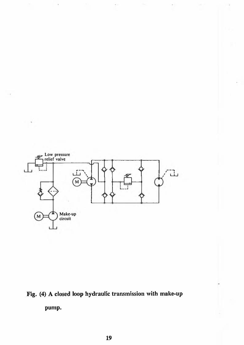
Fig. (4) A closed loop hydraulic transmission with make-up
pump.
19
Perc
ent
of oi
l lit*
ex
pect
ancy
re
sulti
ng
from
50%
loss
for
ever
y 15
* In
crea
se
in op
erat
ing
tem
pera
ture
ab
ove
140*
F.
2203 % ----------
210
6 % ---------- 200
1901 2% ---------- ------
180
2 5 % ---------- 170
1605 0 % ---------- ------
150
0 0 % ---------- 140
130• E3 3 .• • «* > - 0 120
a - 52 110
0 5 ® 100p • £
"¡r40
Mar* ad additional IncraaM In ayatam nolaaa begin within thla ranga of oil lamparatura.
Maximum operating laniparatura lor O p t i m u m oil Ilf*. (ISO S S U oll vlacoalt* drop« to approx.SO 88U at 140* F.)
I) Notlcaabla IncraaM In ayatam nolaa baglna within / thla ranga of oil tamparatura bacauaa oil la thinner ) and tranamlt» aound and vibration wavea bailor.
Maximum recommended operating tamparatura but with reduced oil Ufa.
________________ I
Optimum operating lampara tur*.
Ideal oil lamparatura ranga lor bait ayalem performance andlongaaf oil Ufa.
Loweat advisable alarf-up I am paratura. (Balow 40* F, moat hydraulic fluida ara too vlacoua—fraquantly causing cavitation.)
Fig. (5) The effects of hot oil on hydraulic system
performance.
20

Fig (6) An application of an open simulated hydraulic
system used for lowering and raising the nose wheel
of an aircraft landing gear.
21

Fig (7) An application of a closed hydraulic transmission
system to an undersea submarine research vehicle.

CHAPTER: 2
Design and Commissioning of the Experimental Equipment
2.1. Introduction
In order to test the developed mathematical model, a complete open hydraulic mixer system has been designed, instrumented and commissioned in the laboratory of SCHOOL OF MECHANICAL AND MANUFACTURING ENGINEERING IN DUBLIN CITY UNIVERSITY.
2.2. Experimental Test Rig Components:
Fig (8) and Plate (1) show the selected test rig components required for an open hydraulic drive mixer system which consists of an electric motor, a hydraulic pump, pipelines, control valve, a solenoid directional control valve, a relief valve, a compact sized of hydraulic reservoir, a cooler arrangement and a hydraulic motor coupled with the mechanism of the mixer.
The selection of a gear pump without external drain was made to provide an unit most suitable for test work rather than for any particular mixer hydraulic system application. An external gear motor with an external drain was selected to demonstrate the open circuit
23

design, which is capable of coping with oil circulation in the system due to components flow leakage. The main criterion for the choice of the pump or the hydraulic motor was that they should be capable of easy mounting and / or mechanically as simple as possible.
The choice of the four way three position solenoid directionals control valve was made to allow the reverse of the mixer movement and to unload the pump at the valve central position. All the pipes in the system were chosen as flexible hydraulic hoses to allow the flexibility of arranging installation for the hydraulic transmission system components, and also to mount the mixer at the most convenient operating position.
An adjustable relief valve was selected to limit the maximum system pressure and to protect the hydraulic pump, motor and pipework when the drive is on.
If this system is to be used in mobile or industrial application, it is essential that the hydraulic transmission system should have as small a requirement as possible of the power supply and also the installation space. Therefore, a cooler was selected. The choice of the cooler to be included in this system was made to reduce the size of reservoir in the conventional open system and, to give the opportunity for greater mobility if needed. As a comparison, under the same condition
24
where the electric motor is operated at nominal speed of 1500 r.p.m, the reservoir size in a conventional open system is normally chosen as 6 to 7 times of the system flowrate. This means that a 48 to 56 litres reservoir has to be used.
2.3. Instrumentation of the Experimental Test Rig:
2.3.1. Hydraulic Pump A fixed positive displacement
external gear pump has been selected in this system with maximum flowrate of 3 6 1/min and volume displacement of 24 cm3/rev. Technical data of this pump is summarised in Table (1 ). Fig (9) and Plate (2) show an external gear pump with positive displacement in which the fluid is transferred at a constant amount for each cycle of operation. Since the internal pump volume can not be adjusted, the pump is considered to have a fixed displacement.The pumping action occurs in the gear pump when the input drive causes one gear to turn the other. This action, in turn, causes fluid to be displaced from the inlet port to the outlet port in the following manner. The gear teeth seal as one rotates the other. As the teeth part on the suction side of the pump near the low pressure inlet port, they increase the volume of the inlet chamber causing a slight vacuum. The rotating gear teeth transfer fluid, forced in by atmospheric pressure and trapped in the gear teeth, around the outside periphery of the gears to the high pressure outlet
25

chamber. Meshing of the teeth in the outlet chamber reduces the cavity volume by an amount equal to that displaced between the teeth as they mesh. This forces fluid from the outlet cavity and port at system pressure.
2.3.2. Hydraulic Motor: A fixed positive displacement
external gear motor with external drain has been selected in this system. This motor has a maximum flowrate of 54 1/min and volume displacement of 3 6 Cm3/rev. This external gear positive displacement motor operates in the reverse manner of its pump counterparts. This motor differs from the pump in other respects. Because the case is pressurized from an outside source, an external drain line is provided to protect shaft seals. This drain line is piped directly to the low pressure reservoir as shown in Fig (8) and Plate (8) . technical data of the hydraulic motor is given in Table ( 2 ). Plate (3) shows a view of the hydraulic motor.
2.3.3. Valves:Hydraulic valves provide the interface
between the hydraulic fluid, the control signal and the hydraulic actuators. They are used to control the flowrate, the direction of flow and the pressure of fluid. For instance, the relief valve is used in the present system to first, limit the maximum system pressure which, in turn, protects the system components,
26

piping; and second, limit the maximum output force of the hydraulic system.
All valves, except the directional control valve, which are used in this system are cartridge insert valve type. The advantages of such valves are obvious, because if a control function becomes faulty for some reason, it is a very simple matter to replace it without disturbing any pipework. There is also a saving in the amount of interconnecting pipework. Fig (10) and Plate (8)shows the cartridge insert relief valve which was used in the rig test. All the cartridge insert valves were mounted in valve blocks with screwed port for pipe mounting as shown in Fig (11) and Plate (8). In this case the insert can be replaced without disturbing the fluid connections. Tables (3) to ( 6 ) give the technical data of pressure relief valve, flow control valve, check valve and directional control valve respectively.
2.3.4. Pipelines: All pipes in the system were chosen as
flexible single wire braid hydraulic hoses, as shown in Fig (12) and Plate (3), which allow the flexibility of arranging installations for the hydraulic transmission system components. Tables (8), (9 ) and (10) give thetechnical data of the hose of pressure line, return line and suction line.
27

2.3.5. Reservoir:A compact size stainless steel reservoir
of dimensions (300 mm X 290 mm X 105 mm ) has been used in this system. Figure (13) and plate (4) show a view of the reservoir which contains a fluid level and temperature gauge in the form of a transparent 'window1, a filler cap which includes a strainer to prevent foreign matter entering when oil is being replenished and a breather to allow movement of air through a filter so that dust is not drawn in as the fluid level fluctuates. The pump intake is fitted with a strainer and the return line is fitted with filter 40 micron filtration with condition indicator, 2.0 bar bypass when filter element is blocked. Table (11) illustrates technical data of the reservoir.
2.3.6.Cooler: A 25 row efficient radiator with a maximum
capacity of 15 KW dissipation of heat has been installed in the circuit. Table (12) gives the data of cooler. Plate (5) shows a view of the cooler and Plate (4) shows a view of the cooling unit.
28

2.4. Instrumentation and Measuring Equipment:
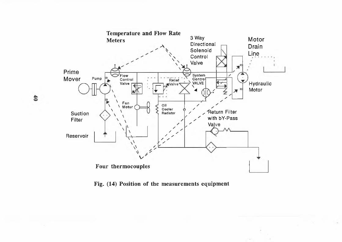
The hose wall temperatures were measured by four thermocouples with a digital output as shown in Plate (6) . These thermocouples were firmly stuck onto the surface of hoses. Fig (14) shows the location of four thermocouples. Fluid temperature in the reservoir was measured with a dial mounted gauge driven by a temperature sensitive fluid that is metal encased and immersed in the hydraulic fluid. The fluid level in the reservoir is monitored by a fluid level gauge which was mounted in the reservoir to indicate the level and the amount of make-up fluid necessary to fill the hydraulic system. The temperature and fluid level gauges are illustrated in Plate (4).
The temperatures of the fluid flowing through the hoses were measured by two temperature meters which have been incorporated in the lines of the hydraulic system to record the change of the fluid temperature during the system operation. Plate (7) shows the inline temperature meters.
The pressure is measured using two pressure gauges to check the conditions of the component and the pressure value of the load resistance. These gauges are filled with a dampening fluid such as glycerine to smooth pulsations that might cause damage to the sensitive gear mechanism. Fig (15) and Plate (7) show the pressure gauges.
29

Flow rate in the system was measured using two inline flow meters as shown in Plate (7) and Fig. (16) . This flow rate meter displays the flow rate in gal/min or litres/min. The flow indicator consists of a sharp edged orifice and tapered metering piston which moves in proportion to changes in flow rate. As the flow increases, the pressure difference across the orifice formed by the metering piston and fixed orifice moves the piston against the calibrated spring. Piston movement is directly proportional to flow rate with the sharp edge orifice minimizing the effects of viscosity.
Actual motor, pump and fan speed were obtained using a remote hand digital reading tachometer which measured the speed of the rotating mark on output shaft. The remote hand held digital tachometer is shown in Plate (2) .
To get the measurements in different parts of the system, quick-disconnect hose couplings are used where frequent connection are made and broken between components. Plate (7) shows these hose couplings.
30

2.5. Experimental Test Rig Layout: a general view of the
open hydraulic drive mixer system is shown in Plate (1) and schematically, in Fig (8).The unit was mounted flat against a bracket using four holes of 11 mm diameter, so that the filler cap and filter are on top and that the control valve, filler cap and sight glass are accessible. Mounting details are shown in Fig ( 17 ) and Plate (4).
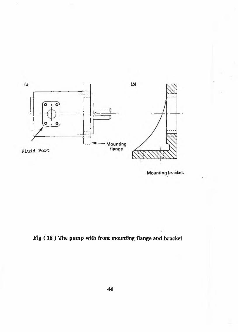
In this experimental rig a 11/8.2 kw Brook electric motor ( Cage Pole change two speed Type ) was positioned on the experimental bench and was coupled together with the chosen fixed displacement pump without external drains shown in Plate (2). The pump was a flange mounted type and an adapter bracket has been fitted in order to provide this way of mounting as shown in Fig (18). The suction port of pump with 38 mm diameter was connected to the reservoir by a 1.5 m length and 38 mm diameter single wired hydraulic hose.
All hoses except pump suction line, were connected via the control block as shown in Plate (8) and Fig. (19), the 19 mm (3/4 inch) diameter high pressure single wired hydraulic hose with length 1.5 m was connected from the high pressure port of the pump to the 19 mm (3/4) inch B.S.P male fitting on the control block and then 3/4 inch B.S.B male fitting on the control block is connected by a 2 m long, 19 mm (3/4 inch) diameter
31

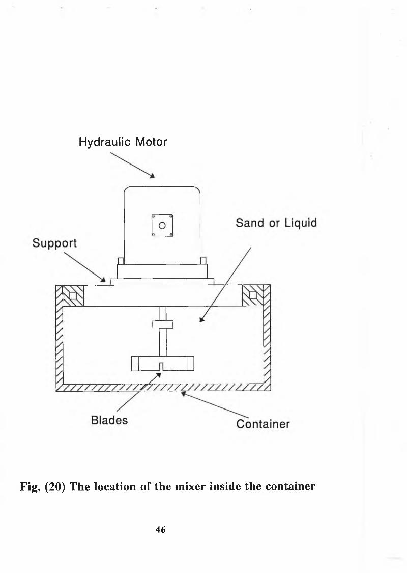
single wired hydraulic hose to the pressure port of a 4 way 3 position at tandem centre position of the solenoid directional control valve with a subplate mounted on four bars placed between the hydraulic motor and pump as shown in Plate (3) for the convenience of operation.The A port of the solenoid directional control valve is connected to one side of hydraulic motor by a 0.3 m length 12.7 mm (1/2 inch) diameter single wired hydraulic hose, while B port of the valve is connected to the other side of the hydraulic motor by a 0.3 m long 12.7 mm (1/2 inch) diameter single wired hydraulic hose. The T port (to low pressure return line) of the directional control valve is connected with 2 m long single wired hydraulic hose of 19 mm ( 3/4 inch) diameter to the 19 mm (3/4 inch) B.S.P male fitting on the control block.The hydraulic motor was fixed vertically on a mild steel frame which was welded to the top of the container 2.0 m away from the reservoir. The mechanism of the mixer consists of four blades which is connected to the hydraulic motor by a shaft and placed in the container in 0.3 m of the mixing material to provide a load condition as shown in Plates (3) and (9). Technical data of the mixer is given in Table (13). The location of the mixer in the container is illustrated in Fig (20) The 12.7 mm (1/2 inch) diameter drain port of the hydraulic motor was connected to 25.7 mm (1/2 inch)B.S.P female fitting on the reservoir by 2 m long, 12.7 mm
32
(1/2 inch) diameter single wired hydraulic hose.A detailed listing of technical data for the test rig is given in Table ( 14 ) .
33

3 Way Motor
Fig (8) An open hydraulic drive mixer test rig

Low pressure inlet
Internal seal formed
here
Internal seal formed
here
Unbalanced forces caused by pressure
at the outlet
High pressure outlet
Fig ( 9 ) External hydraulic gear pump
35

Pressureport
Tank port
fig ( 10 ) The cartridge insert relief valve
36

II
Fig ( 11 ) Valves block assembly
37

Cotton layer Steel wir«
Fig ( 12) Structure of a single flexible wire braid hydraulic
hose
38

Fig ( 13 ) Structure of the hydraulic reservoir
39
Temperature and Flow RateMeters 3 Way
A Directional*
\N
SolenoidControlValve
PrimeMover Pump
Flow Control Valve
O f © ' m :-lo?Relief
(Valve
System Control VALVE \
SuctionFilter
Reservoir
o► N Fan I
' ^ V Motor (2^ V OilCoolerRadiator
\
- < $ • '
MotorDrainLine
//
o HydraulicMotor
//
y// / ' / //
/ ' s Return Filter/■ //ys
\\ //
with bY-Pass Valve
VFour thermocouples
Fig. (14) Position of the measurements equipment
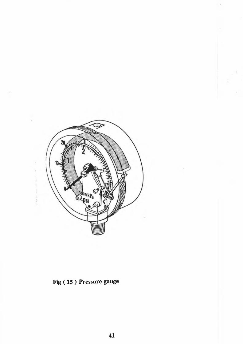
Fig ( 15 ) Pressure gauge
41

O p e r a t i o n
Typical Pressure Drop Curves Oil Viscosity 25 Centistroket 100 SSU
Symbol
Fig ( 16 ) Flowrate and temperature meter
42

4 Ho
les
011m
m
Air O u t.£CO
Fig (17) Mounting detail o f the unit.
f
Fig (18 ) The pump with front mounting flange and bracket
44

1. 1/2”BSP. Drain plug2. Motor return ” BSP. ’M’3. Pump ” ” ” ”4. Pr. to Motor ” ”5 Suction to Pump 1 .V ’ BSP.’M’
Fig ( 19 ) Position of drain, pump and hydraulic motor port
in the control block
45
Hydraulic Motor
Fig. (20) The location of the mixer inside the container
46

Name of Component Pump UnitType: External Gear 1LA3 0DEMaximum Flowrate at 1500 rpm 36 L/min
Displacement 24 Cm3 /revContinuous Maximum Pressure 220 Bar
Maximum Speed 3000 r .p.m
Table (1) Technical data for hydraulic pump
Name of Component HydraulicMotor UnitType: External Gear MPLA54
Maximum Flowrate at 1500 r.p.m 54 L/minDisplacement 36 Cm3/revContinuous Maximum Pressure 220 BarMaximum Speed 2800 r.p.m
Table (2) technical data for hydraulic motor
47
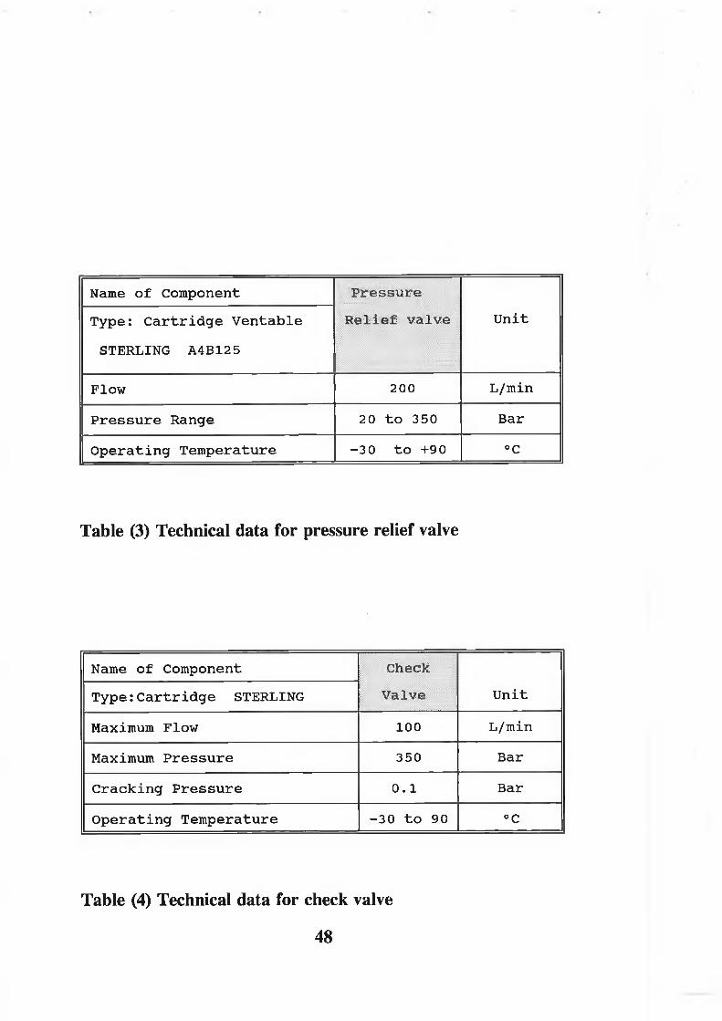
Name of Component Pressure Relief valve UnitType: Cartridge Ventable
STERLING A4B125
Flow 200 L/minPressure Range 20 to 350 BarOperating Temperature -30 to +90 °C
Table (3) Technical data for pressure relief valve
Name of Component CheckValve UnitType: Cartridge STERLING
Maximum Flow 100 L/minMaximum Pressure 350 BarCracking Pressure 0.1 BarOperating Temperature -30 to 90 °C
Table (4) Technical data for check valve
48

Name of Component FlowControlValve
UnitType: Flow Regulator Restrictive STERLING J2A60
Flow 2-40 L/minPressure Range 20-350 BarOperating Temperature -30 to 90 °C
Table (5) Technical data for flow control valve
Name of Component Directional:ControlValve
Unit
4 Way 3 Position Solenoid
Maximum Flowrate 100 L/minMaximum Pressure 250 Bar
Table (6) Technical data for directional control valve
49
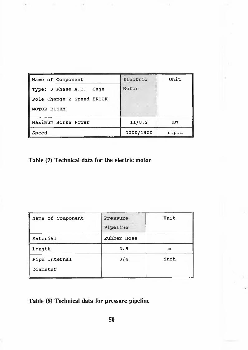
Name of Component ElectricMotor
UnitType: 3 Phase A.C. Cage Pole Change 2 Speed BROOK MOTOR D160M
Maximum Horse Power 11/8.2 KWSpeed 3000/1500 r .p.m
Table (7) Technical data for the electric motor
Name of Component PressurePipeline
Unit
Material Rubber HoseLength 3.5 mPipe Internal Diameter
3/4 inch
Table (8) Technical data for pressure pipeline
50

Name of Component
Pressure Return Liner.. . . . . . . . . . . .
-
Unit
Material Rubber HoseInternalDiameter
3/4 inch
Length 2 m
Table (9) Technical data for pressure return line
Name of Component
Pressure Suction Line.....! Unit
Material Rubber Hose
Length 1.5 m
InternalDiameter
1.5 inch
Table (10) Technical data for pressure suction line
51

Name of componentReservoir
; . . . u..SS- : v., . . . . '
. . . ::::
UnitType: Reservoir top is not open directly to its surrounding atmosphere
Material StainlessWidth of Reservoir Base 105 mmLength of Reservoir Base 300 mmHeight of Reservoir 340 mmCapacity of Reservoir 8 Litre
Table (11) Technical data for hydraulic reservoir
Name of ComponentCooler
' :UnitType: Hydraulic Oil
Radiator
Maximum flowrate 80 L/minMaximum Heat Dissipation 15 KWVolumetric Size 3 Litre
Table (12) Technical data for hydraulic oil cooler
52

Name of Component Mixer Unit
Diameter 300 mm
Initial Angular Velocity 0 r.p.m
Number of Blades 4
Table (13) Technical data for the mixer
53

No---------------------------------------- -—
Component Name Technical Data Unit1 Electric Motor Horse Power at 8.2 KW3 Hydraulic
Motor With External Drain
MaximumDisplacement
36 Cm3/rev.
Maximum Pressure 220 Bar
4 High Pressure Pipeline
Hose Diameter 3/4 inch
5 Low Pressure Pipeline
Hose Diameter 3/4 inch
6 Suction Line Hose Diameter 1.5 inch
7 Relief Valve Maximum Flowrate 200 L/minMaximum Pressure 350 Bar
8 Check Valve Maximum Flowrate 100 L/minMaximum Pressure 350 Bar
9 Flow Control Maximum Flowrate 40 L/minMaximum Pressure 350 Bar
10' ' 1 VC4 way 3 Position Solenoid Directional Control Valve
Maximum Flowrate 100 L/min
Maximum Pressure 300 Bar
11 Reservoir
12 Cooler Maximum Flowrate 90 L/minHeat Dissipation 15 KW
Volumetric Size 3 L
Table (14) Technical data for experimental tes rig
54

MIXERGENERAL VIEW OF THE OPEN HYDRAULIC DRIVE SYSTEM

HYDRAULIC MOTORSOLENOID DIRECTIONAL CONTROL VALVE
"Ss
. . ■ 5
% ' : • -V
• ' v;;i’̂4r.pBPWI
• V>-— ;
CONTAINER
PRESSURE LINE
RETURN LINE
SUCTION LINE

¡ j f w j,., a
FLUID LEVEL GAUGE
COOLING UNIT
PLATE 4

IK
I iwmmmmmwwmm
l^nwmwiwmwíwmwm
Ir&mwnmmwm'mwmi r^mMWkWSiiwwihWM
S B S Sm w p sw m m


INLINE TEMPERATURE AND FLOW RATE METERS
3T75S.

.r- sv
QUICK-DISCONNECT HOSE COUPLINGS
....
;;j j*. v*
-‘S'm'
•-Ör25W< 1

SYSTEM CONTROL VALVE
RELIEF VALVE VALVES CONTROL BLOCK
MOTOR DRAIN LINE

CHAPTER: 3
MATHEMATICAL MODEL AND SIMULATION
3.1. Introduction: In order to study and predict the
temperature behaviour in any hydraulic system, it is important to develop a suitable mathematical model. As a first step, such a model has been developed in this study based on the assumption that the hydraulic system is an open system. The mathematical model is applied to analyze the temperature distribution in an open hydraulic mixer system. The power losses is converted into heat energy which causes the variations in the system temperatures. In a practical hydraulic system, the fluid temperature is different from the wall temperature of the pipes in the loop because of the heat flow transferred to the loop surrounding the operating system.
3.2. The present analysis: The analysis reported in
references (13) and (14) was developed based on the assumption that 1) both the inside and outside pipe wall temperatures of the system were the same as the fluid temperature.
6 4

2) the heat generated by the pressure losses due to pipe friction were negligible.
Assumption (1) implies that the heat transfer process in which the rate of heat transfer by conduction and convection through the system pipe walls has been ignored. Therefore, this assumption may lead to errors in predicting the accurate fluid temperature in a practical hydraulic system. Assumption (2) is unreasonable since in some systems friction generates heat energy which should be taken into account.
In the present work a mathematical model for temperature analysis is developed to consider a hydraulic system (such as the open hydraulic mixer system) as an open thermal system in which the fluid temperature throughout the circuit and the pipe wall temperature are also uniform throughout the circuit. In addition, in this analysis the differences between the fluid and pipe wall temperatures have been considered so that the transient difference in the heat flows transferred from fluid to the pipe wall and from the pipe wall to the system surrounding atmosphere can be estimated to predict transient behaviour of outside pipe wall temperature. Furthermore, the rate of heat transferred by conduction, convection and radiation and, the heat generated by the pressure losses due to pipe friction
65
have been taken into account. The present theoretical analysis also, has been improved to include the differences in pipe wall temperatures at the different parts of the system pipelines due to different pipe wall materials.
In this work the system main loop is considered as an open thermal system where uniform temperature is assumed in the loop fluid, while the reservoir is another open thermal system. Hence, the fluid energy exchanges between the loop and the reservoir can be estimated. However, in a practical hydraulic system differences exist between fluid temperatures of the system pipelines in the main loop due to the differences in the heat generation in the different parts of the system. So, a further study for analysis of the thermodynamic processes in a hydraulic system has been investigated in this thesis. The aim of that is to consider the hydraulic system loop as a series of open thermal systems with a constant fluid temperature in each part of the system so that the difference between fluid temperatures in the loop of the system can be calculated.
Before outlining the analysis, it was felt necessary to give a brief summary of some relevant fundamental thermodynamic concepts. The theory of the First Law applied to an open thermal system has been used to
66
derive some equations in order to analyze basic thermodynamic and heat transfer processes associated with an open pipe section of hydraulic systems. This set of equations can then be applied for temperature analysis in the hydraulic system.
3.3. Closed and Open Thermal Systems: The concept of a
system plays an important part in thermodynamics; it may be defined as a region in space containing a quantity of matter whose behaviour is being investigated. This quantity of matter is separated from its surrounding by a boundary, which may be a physical boundary, such as the wall of pipes, or some imaginary surface enveloping the region. Before any thermodynamics is attempted it is essential to define the boundary of the system, because it is across the boundary that work and heat are said to be transferred. The term surroundings is restricted to those portions of matter external to the system which are affected by changes occurring within the system. When the same matter remains within the region throughout the process under investigation it is called a closed system, and only the work and heat cross the boundary. An open system, on the other hand, is a region in space defined by a boundary across which matter may flow in addition to work and heat.
3.4. The First Law for Open Systems: it is known that the67

first law of thermodynamics is applied to a closed thermal system where no mass flow crosses the boundary.But, in most engineering applications it is difficult to separate a mass of the working substance and treat it as a closed thermal system. Zeuner (32) and Gillespie and Coe (33) suggested that it is possible to regard the continuous flow process as a series of non flow processes undergone by an imaginary closed system, as shown in Fig (21) which illustrates this concept. The same concept was also suggested by Keenan in Reference (34). However, in this way continuous flow may be regarded as a succession of these non-flow processes, carried out for every element of fluid entering the open system. Therefore, it now becomes possible to apply the energy equation which has been developed from a study of closed systems. The application of First Law of Thermodynamics in a closed system are well referenced by Bejan (35), McConkey (36), Wallace (37), and Look and Sauec (38). The first Law of Thermodynamics for a closed system can be written on a per unit time basis
Q ~ W = M (!)d t
The following analysis will later be applied to a length of pipe as a part of a hydraulic system. Fig.(22) shows the main features of an open system, namely

heat transfer interactions per unit time, Q; work transfer interactions per unit time W; and portions of the boundary that are crossed by the flow of mass. For simplicity, this Figure shows only one of each type of boundary crossing, one inlet port labelled "in," and one outlet port labelled "out." The open system, or the control volume, is the rectangular region contained between the inlet and outlet ports, in other words, the dashed lines labelled "in" and "out" are part of the boundary of the open system.
Since equation (1) applies strictly to closed system, it must first identify a system with a fixed mass inventory that is unambiguously related to the open system of interest. If is the mass inventory ofthe open system at a certain point in time t, then it can be thought of as the fixed mass inventory Mclosed that at time t flows through the control volume. According to Fig (22), the relationship between and Mclose<j is as follows:
Mc i og9t j ( C O R S t & R t ) ~ ^open , ^open , (t+At) + ^ ^ o u t l e t
For the process from state (1) (time t) to state (2) (time t+At) executed by the closed system, the First Law of Thermodynamics (1) reads:
E c lo s e d . (t+At) ~ ^ c lo s e d , t - (VA t + ( P A V ) i n l e t ~ ( P A V ) ou t ( 3 )
6 9
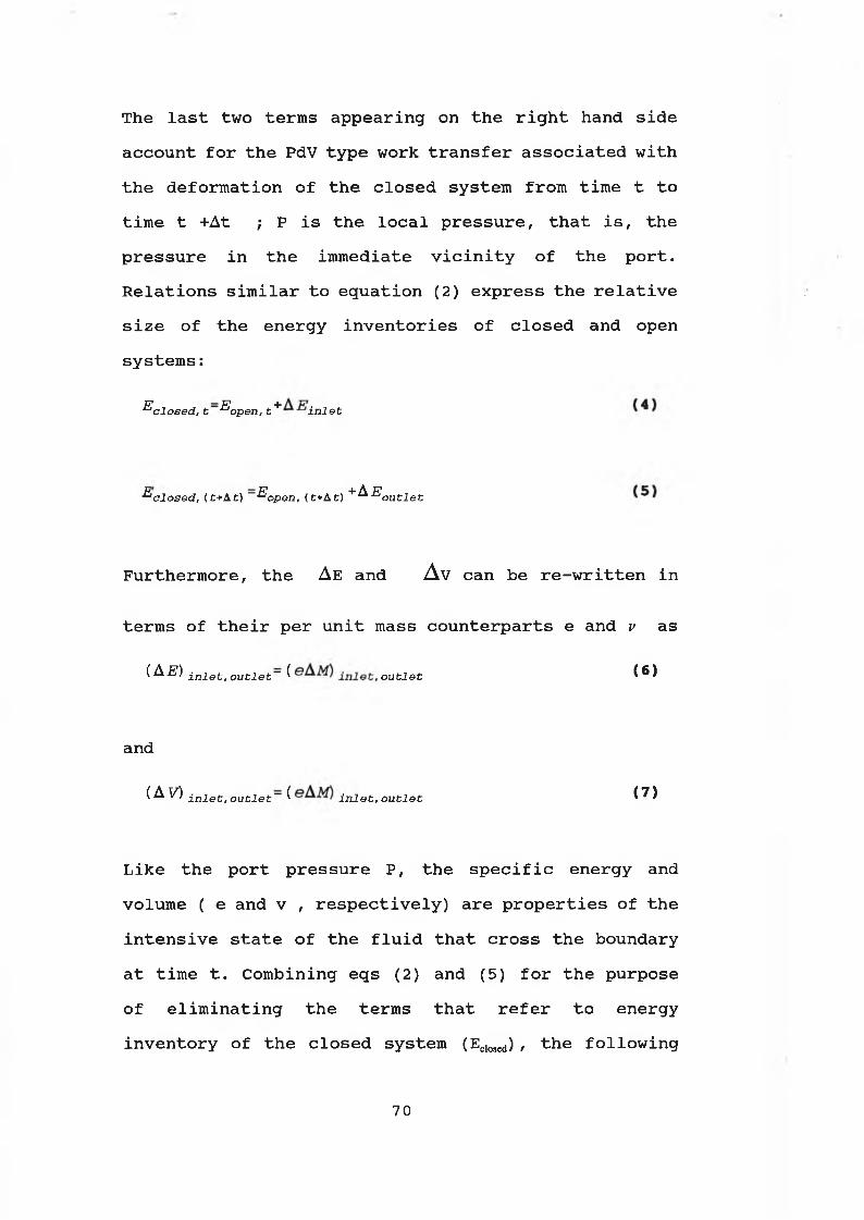
The last two terms appearing on the right hand side account for the PdV type work transfer associated with the deformation of the closed system from time t to time t +At ; P is the local pressure, that is, the pressure in the immediate vicinity of the port. Relations similar to equation (2) express the relative size of the energy inventories of closed and open systems :
^ c l o s e d , t~ ^ o p e n , t + i n l e t
^“c lo s e d , { t+ At) ^open , (t+At) + ^ E o u t l e t
Furthermore, the Ae and Av can be re-written in
terms of their per unit mass counterparts e and v as
( A E ) i ni e t ' out l e t ~ ̂ o u t l e t ̂® ^
and
( ^ ^ i n l e t , o u t l e t ~ ( j nJet , o u t l e t i ? )
Like the port pressure P, the specific energy and volume ( e and v , respectively) are properties of the intensive state of the fluid that cross the boundary at time t. Combining eqs (2) and (5) for the purpose of eliminating the terms that refer to energy inventory of the closed system (Eclosed) , the following
70

e q u a t i o n i s o b t a i n e d :
(Eop„, ,e.at) -E opm, t =Q-W+ [ (e+Pv) M ] inlec- [ (e + P v)<8)
Invoking the limit At ~^ 0, writing m for mass
flowrate AM/At, dropping the subscript "open" from the energy inventory of the control volume, and allowing for the existence of more than one inlet port and outlet port, the most general statement of the First Law of Thermodynamics for an open system is obtained as:
=Q-W+ ^2 in (e+Pv) - ^2 m (e+P v) (9)i n l e t o u t l e t
What makes this statement more general than the per unit time version of the first law for closed systems, is the presence of the terms m(e+ Pv) . These terms represent the energy transfer associated with the flow of mass across the system boundary. Finally, in the absence of macroscopic forms of energy storage other than kinetic and gravitational ones, the specific energy e can be decomposed into (u+%V2+gz) see Reference 35. The results of this decomposition is that of the s p e c i f i c e n t h a l p y , h , w h e r e
71
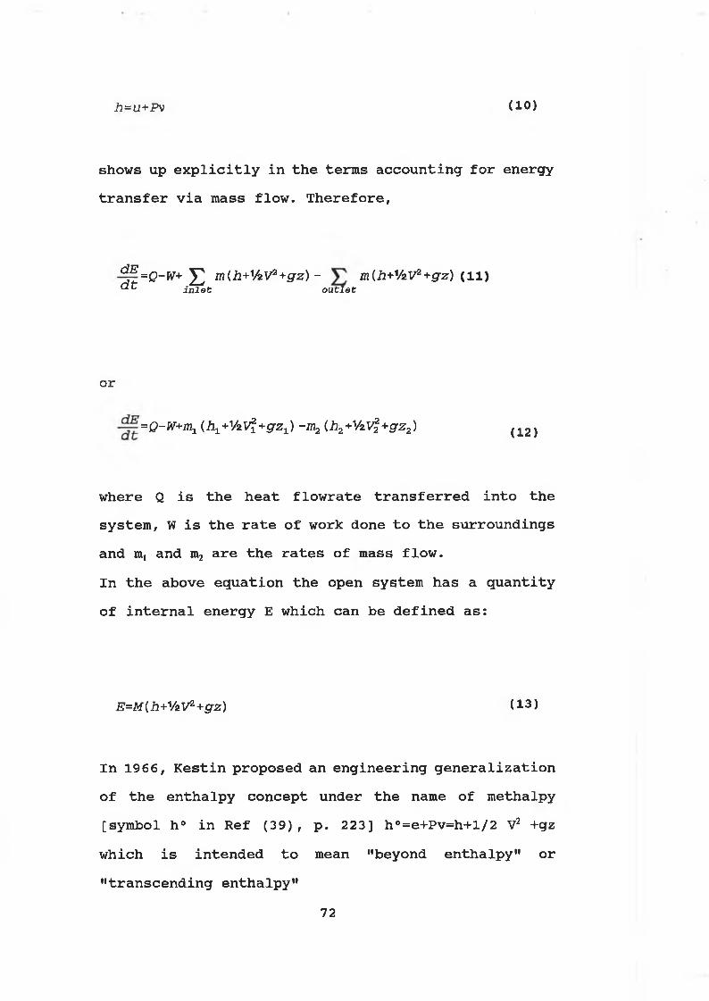
h= u+Pv ( 10 )
shows up explicitly in the terms accounting for energy transfer via mass flow. Therefore,
^e =Q-W+ ^2 m(h+VzV2+ gz) - m{h+V2V2+ gz) (li)d t i n l e t o u t l e t
or
=Q-W+m^ U i^ V zV i+ g zJ -m2 (h2+VzV%+gz2) (12)
where Q is the heat flowrate transferred into the system, W is the rate of work done to the surroundings and mt and m2 are the rates of mass flow.In the above equation the open system has a quantity of internal energy E which can be defined as:
E = M { h + V z V 2 + g z ) ( 1 3 )
In 1966, Kestin proposed an engineering generalization of the enthalpy concept under the name of methalpy [symbol h° in Ref (39), p. 223] h°=e+Pv=h+l/2 V2 +gz which is intended to mean "beyond enthalpy" or "transcending enthalpy"
7 2

3.5. Fluid Temperature in a Pipe Section of a Hydraulic
System: Any specific length of pipe in a hydraulic
system can be regarded as an open thermal system undergoing a thermodynamic process as shown in Fig.(23). The amount of work W transferred into the pipe section due to the power loss caused by the pressure loss in the pipe at each end of the pipe section will be converted into heat. The energy transfer taking place across the boundaries of the system is the heat energy Qfc which represents heat transferred from fluids to the pipe wall by the forced convection. The mass transfer occurs simultaneously with energy transfer flow with rate of Qj and temperature of T^is entering the system in which outlet flow has temperature of Tf and rate of Q2
If a uniform fluid temperature is assumed within the open section of the pipe, and the change in fluid kinetic and potential energies for a specific hydraulic pipeline are negligible, the thermodynamic flow process associated with the section of the pipe can be studied by applying Equation (12) for open thermal system, i.e
Jj£ = Q 1-W+m1h1-m2h 2 ( 1 4 )
Substituting Equation (13) into Equation (14) to
73
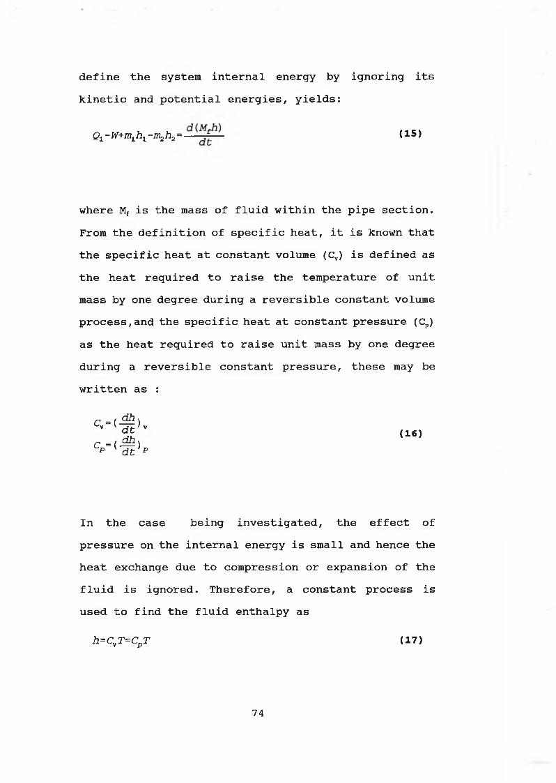
define the system internal energy by ignoring its kinetic and potential energies, yields:
Q x - W +m ^h^ - m 2h 2= — ■ ( 1 5 )
where Mf is the mass of fluid within the pipe section. From the definition of specific heat, it is known that the specific heat at constant volume (Cv) is defined as the heat required to raise the temperature of unit mass by one degree during a reversible constant volume process,and the specific heat at constant pressure (Cp) as the heat required to raise unit mass by one degree during a reversible constant pressure, these may be written as :
C = ( ^ )V ' J * - ' VH <16>c ={ — ) p K d t p
In the case being investigated, the effect of pressure on the internal energy is small and hence the heat exchange due to compression or expansion of the fluid is ignored. Therefore, a constant process is used to find the fluid enthalpy as
h=CvT=Cp T (17)
74

Using the above equation in equation (15), gives :
01-W+m1Cr T1„le t -m2CpTt ‘ d ( * W V > ( 1 8 )
where Tf is assumed to be the uniform fluid temperature. The above equation can also be written as
d TQ1 - W +m 1 Cp T l n l e t - m 2 Cp T f = M f C p - ^ - + m f Cp T f ( 1 9 )
In this equation, the mass flowrate at any instant of time is expressed m^mj-mz. In practice, the mass flowrate through a pipe section is generally assumed to be constant. Therefore, the equation (19) can be re-written as:
d TMf Cp - J § = 0 l ~ W+m f Cp ( T i n l e t - T f ) ( 2 0 >
The transient term (MfCpf dTf/dt) has always been ignored by others in the previous studies due to the only consideration of the steady state. This term, however, could be more significant for the transient fluid temperature changes in any hydraulic system.
75

In the above equation, the rate of heat flow Q! transferred from fluid to the pipe wall is defined through the following extensive considerations
7 6
3.6. Heat Transfer through a Pipe Wall in Hydraulic System:
Basic theoretical studies of heat transfer have been established for years. For instance, Holman (4 0) , Yildiz and Mecati (41), Rogers and Mayhew (42), and Adam (43) have studied extensively in terms of this subject. For the benefit of the reader a brief
summary is given for applying the theory to the analysis of the pipe wall temperature in a hydraulic system.
Heat transfer is that science which seeks to predict the energy transfer which may take place between material bodies as a result of a temperature difference. Thermodynamics teaches that this energy transfer is defined as heat. The science of heat transfer seeks not merely to explain how heat energy may be transferred, but also to predict the rate at which the exchange will take place under certain specified conditions.
In studying heat transfer it is customary to consider three distinct mechanisms of heat flow: conduction,convection, and radiation.
1) Conduction: Conduction is the transfer of heat from
one part of a body at a higher temperature to another part of the same body at a lower temperature, or from
7 7
one body at a higher temperature to another body at a lower temperature in physical contact with it.
2) Radiation: Radiation, or more correctly thermal
radiation, is electromagnetic radiation emitted by a body by virtue of its temperature and at the expense of its internal energy. Thus, thermal radiation is of the same nature as visible light, x ray, the difference between them being in their wave lengths and the source of generation.
3) Convection: Convection relates to the transfer of
heat from a boundary surface to a fluid in motion, or to the heat transfer across a flow plane within the interior of flowing fluid. If the fluid motion is induced by a pump, a blower, a fan, or some similar device, the process is called f o r c e d c o n v e c t i o n . If the fluid motion occurs as a result of the density difference produced by the heat transfer itself, the process is called f r e e o r n a t u r a l c o n v e c t i o n .
It is generally possible to calculate the heat transfer by each mode separately and then sum up the results. In this way a complex problem can be resolved, and the relative importance of the various modes of heat transfer can be assessed.
78

In the present analysis the heat transfer radially through the pipe wall material only is discussed,and the effects of conduction, radiation and convection are investigated.
3.6.1 Forced Convection: The study of heat transfer by
forced convection is usually concerned with the calculation of rates of heat exchange between fluid and solid boundaries. Because the fluid is flowing past the inside wall, a condition of forced convection applies to heat transfer across the wall as in Fig.(24) which shows a view of a pipe section containing the heat transfer at any instant of time. Qj expresses the rate of heat transferred from moving fluid to the pipe wall due to the forced convection arising from the movement of the fluid. It is known that the transfer of heat by forced convection can be written as :
Q ^ h ^ i T f - T j (21)
where Ai is the inside surface of the pipe section, hf is the forced convection heat transfer coefficient which depends on the Nusselt number N„ =h.L/k. Here L is the characteristic linear dimension and k is the thermal conductivity of fluid.
The value of the Nusselt number for the forced
7 9

convection in fully developed laminar flow through a tube is given in Refs (3 6) and (42) as follows:(1) Nu=3.65 for laminar flow in a tube at constant wall temperature boundary condition;
(2) Nu= 4.3 6 for laminar flow in a tube at constant heat flux which is equivalent to constant temperature gradient at the wall
As the case being investigated is a tube which is heated by flow passing through it, case (2) applies in evaluating heat transfer coefficient by forced convection at the inner surface of the pipe wall.
When the flow is turbulent, Reynolds analogy and dimensional analysis can be applied. The conclusions of these analysis may be summarised by introducing the Nusselt number, Nu, where
N = K F \ ( P r ) ( R e ) ) ( 2 2 )
In above, the Prandtl number Pr and the Reynolds number Re are defined as Pr=V /x/k and Re=p V L//z, V is the fluid velocity . Experiments can be performed in order to evaluate K and to determined the function F. From such experiments the Nusselt number for turbulent flow through tube has been given in Refs.
80
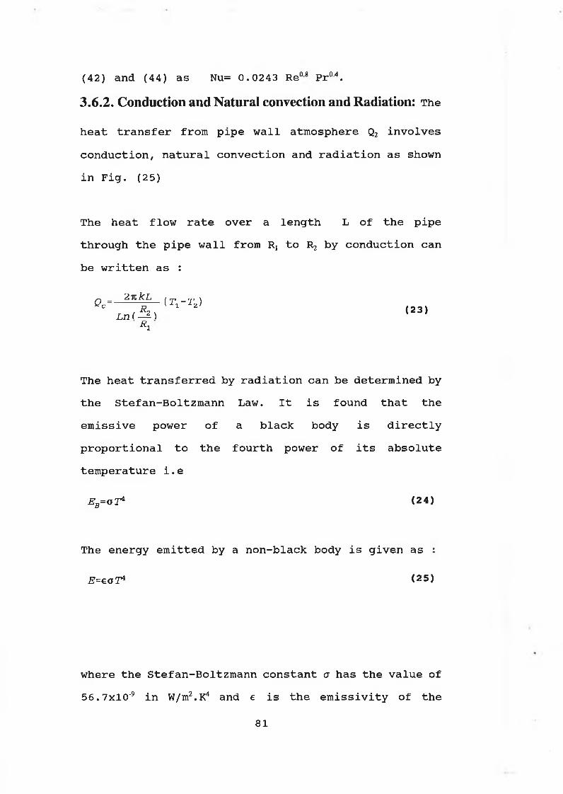
(42) and (44) as Nu= 0.0243 Re08 Pr04.3.6.2. Conduction and Natural convection and Radiation: The
heat transfer from pipe wall atmosphere Q2 involves conduction, natural convection and radiation as shown in Fig. (25)
The heat flow rate over a length L of the pipe through the pipe wall from Rt to R2 by conduction can be written as :
0 C= 2 * k L ( T , - T 2 )
L n A ( 2 3 )1̂
The heat transferred by radiation can be determined by the Stefan-Boltzmann Law. It is found that the emissive power of a black body is directly proportional to the fourth power of its absolute temperature i.e
E ^ o l 4 ( 2 4 )
The energy emitted by a non-black body is given as :
E = e a T 4 ( 2 5 )
where the Stefan-Boltzmann constant a has the value of 56. 7xl0'9 in W/m2.K4 and e is the emissivity of the
8 1

body.Similarly, the energy emitted by the black surroundings is given by
Eb=o T* (26)
Also it is noted that the energy emitted from one body, like the wall of a pipe section, is completely absorbed by the surroundings. Thus, the heat transferred from the body to its surroundings is given as
Qr =eoA2 ( l î - l i ) (27)
where A2 is the outside surface area of the pipe section. Hence, the flow transferred from the wall to its surrounding atmosphere by conduction,natural convection and radiation, Q2, can be expressed as:
f t — <i i - r 2) =hsA2(r2- r a) +6oa2 (tJ -tJ)L n & ) <28)
R1
where ha is the heat transfer coefficient of free convection, Tj and T2 are the uniform inside and outside pipe wall temperatures respectively, Ta is the atmospheric temperature surrounding the pipe section. The value of e for commonly used pipe wall material in
82

hydraulics is given in Table (15) taken from Ref. (45) . If the variation of Ta is assumed to be insignificant compared to other factors, then Ta can be regarded as a constant value during the system operation. The heat transfer coefficient by natural convection ha can be similarly found from experiment. Experimental values for ha are to be found in various handbooks. For instance, Ref. (40) gives a relation for a natural convection for a horizontal pipe as
h = 1.32(4)7 when 1014(Gr<109d (29)l
h a=1.250 3 when 109(Gr(l012
In the above equation, ha is in W/m.K, 6 is the temperature difference in K and d is in m. The Grashof number Gr is defined as Gr=(gL3 /3 6) / v , where g is the gravitational acceleration, L is the linear dimension, $ is the coefficient of cubical expansion and v is the kinematic viscosity. Simplified formulae for natural convection for both the laminar and turbulent range in the different configurations are taken from Fig (22.16), Ref. (42) and summarised in Table (16).
3.7. Pipe Wall Temperature in Hydraulic System: in the
s t e a d y s t a t e , t h e h e a t f l o w t r a n s f e r r e d i n t o t h e p i p e
w a l l Qj m u s t b e e q u a l t o t h e h e a t t r a n s f e r r e d o u t , Q2.
Under the unsteady condition, the difference between Qj and Q2 must be equal to the increment of the pipe wall internal energy. In other words, if the pipe wall is regarded as a closed thermal system, the heat flow supplied to the pipe wall must be equal to the gain in internal energy. Hence;
<30>
From equations ( 13) and (17) :
d E _ d ( M p Cp T 2 ) ( 3 1 )d t d t
where the inside and outside surface pipe wall temperature T, and T2, are assumed to be uniform and both change at the same rate .Thus, equation (3 0) becomes:
d T ' (3 2 )=n -r ' '
where the constant mass Mp and the specific heat Cp of the pipe wall material are noted. The values of Cp for usual pipe wall materials and oil used in hydraulics are listed in Table (17) quoted from Ref. (45).
If the rate of heat flow through the pipe wall is
84

assumed to be transferred under one dimensional conditions, then the heat radial flows through the pipe wall can be expressed by Fourier's Law as:
k A j ^ - T ^Rz -R x
where k is the thermal conductivity of the pipe wall in W/m.K. The values of k for often used pipe materials in hydraulics can be also obtained from Ref. (45) and a brief selection is given in Table (18). In the above equation, A,„ is the logarithmic mean area and can be calculated from :
_ 2 i tL(RZ~R1) _ A2-A ±
A “ 7 ~ r 2 < 3 4 >L n — L n—i?j_ Rx
where L is the length of the pipe section, Rj and R2 are the internal and external radiuses of the pipe section. This rate of heat transferred through the pipe wall by conduction must be equal to the rate of heat transferred from fluid to the pipe wall by forced convection at the boundary of the inner surface of the pipe section. From equation (21) and (33) we have
( T f - T ± ) = ^ T̂ 2- ( 3 5 )
85

Re-arranging the above equation, the inner pipe wall temperature can be written as
JcAh fAi Tf +-ET-lTT:2
(36)¥ 1 ' i?2 R ±
In summary the fluid temperature and pipe wall temperature in a section of the pipe at any instant of time can be determined by solving the following simultaneous equations:
ft =1.32 (— ) 1 (37)a W
(T l~T2) =i2̂ (r2-rA) +eoA2 ( 7 i - 7 i)L n -Z
R 1
h fA1Tf +' kA— T2 ^ f R z - R i 2
h f A 1 -„
R 2 ~ R i
Q 1 = h t A 1 ( T f ~ T x )
( 3 9 )
( 4 0 )
86

where Cpp is the specific heat of pipe wall. Cpf is the specific heat of fluid, e is the emissivity and k is the thermal conductivity of the pipe wall material.
If the initial conditions are given, the equations can be used to calculate the fluid temperature Tf and the pipe wall temperature T2 by applying the numerical integration techniques which are used in computer simulation.
3.8. A Mathematical Model for Temperature Analysis in an
Open Hydraulic System: In an open hydraulic system in
which a reservoir is used, there exists flow energy transfer between the fluid in the reservoir and in the loop. The fluid in the loop is in general considered to be at a different temperature than that of the fluid in the reservoir. If the loop and reservoir fluid temperatures are assumed to be uniform, the hydraulic system may be considered as two open thermal systems; the loop and the reservoir.For the open thermal system of the loop, the transient fluid temperature can be predicted by applying equation (42), so that :
dTf _ Y . W ~Y Qi +mf Cpf ( TRes~Tf ) ( 43)d t ~ Mf cpf
In the above, £ W is the total losses, £ Q1 is the total heat flow transferred from fluid to the pipe walls by forced convection. Mf is the total mass of fluid in the system loop, % is the mass flowrate exchange between the loop and the reservoir TRes is the uniform reservoir transient fluid temperature and Tf is the uniform loop transient fluid temperature. In order to find an appropriate theoretical value of the loop fluid temperature, a reservoir temperature model is necessary to determine the uniform fluid temperature in the reservoir.
88

3.9. An Analytical Model for Temperature of Reservoir in
Hydraulic Systems:
In practice, the fluid and wall temperatures in a reservoir are different from one specific point to another depending on its position relative to the ports of the inlet and outlet pipelines, but these temperature differences are relatively small. Therefore, the fluid temperature and the reservoir wall temperature may be assumed to be uniform but different in the fluid and pipe wall. In reality there may be same difference in fluid temperature at different points of the circuit. This could be true for the pipe wall temperature. However, such difference will depend on the size and type ofhydraulic circuit. If the difference substantial then same error will arise in the predicted results. Fig.(26) shows a reservoir in which the flow is consideredto be an open thermal system.
The heat flow transferred through the verticalreservoir by conduction can be expressed as:
Q Vrcond = ^ § ( A ^ 3) (2 V -3 V .J ( 4 4 )
and the heat flow transferred from the outside vertical reservoir wall to its surrounding atmosphere by natural convection is given by :
8 9

Q vicon v 2 h aTV(A2+A$) (^ vw i ^a) (45)
In the above equation, h^ is in W/m.K, and T„ arethe outside vertical reservoir wall and surroundings atmosphere temperatures respectively ,in K.According to Reference (40)
h = 1 . 4 2 ( T- w v r ~ - - a ) 7 Wh e n l 0 4<Gr<109arv L ( 4 6 )l
h arv=l . 31 ( T wvr~Ta.) 3 W hen 1 0 9( G r ( l 0 12
where Gr is defined as :
cr_ gL3pp2(Twr- r a) _ C7L3P (T ^ -r ,) (47)|A2 V 2
The heat conducted through the vertical reservoir wall must be equal to the heat convected from outside of the reservoir wall into the ambient at temperature Ta. Therefore, an energy equation can be stated as
£i*=2 | U 2-^3) =2h a z v ( A 2 + A 3 ) (rwr-ra) ( 4 8 )
This equation can be rearranged as
90
w h ic h a f t e r e l i m i n a t i n g b eco m es
Tf-Tn =____________ r a__________S 1 ( 5 0 >
2 k(A2 +A3) + 2 hazv(A2 +A,)
w here Q1R i s t h e h e a t f lo w by c o n d u c t io n and c o n v e c t i o n
from t h e f l u i d i n t o i t s s u r r o u n d in g a tm o sp h ere a t
v e r t i c a l w a l l o f t h e r e s e r v o i r .
The h e a t c o n d u c te d th ro u g h t h e h o r i z o n t a l w a l l o f t h e
r e s e r v o i r b ottom can be e x p r e s s e d a s :
Qhrcon d ~ \ ^ f - T Iwp) ( 5 1 )
and t h e h e a t f lo w t r a n s f e r r e d from t h e o u t s i d e
h o r i z o n t a l w a l l o f t h e r e s e r v o i r b ottom t o t h e
su r r o u n d in g a tm o sp h ere by n a t u r a l c o n v e c t i o n can be
•SSSPWwr.) (52.In t h e same way, t h e h e a t f lo w by c o n d u c t io n and
c o n v e c t i o n from t h e f l u i d i n t o t h e su r r o u n d in g
a tm o sp h ere a t t h e h o r i z o n t a l w a l l o f t h e r e s e r v o i r can
be g i v e n a s

T,-Tt( 53 )
■ ^ 1 ^aipA i
w here S i s t h e t h i c k n e s s o f t h e r e s e r v o i r w a l l i n m
and haip i s t h e h e a t t r a n s f e r c o e f f i c i e n t by n a t u r a l
c o n v e c t i o n a t t h e b ottom o f t h e r e s e r v o i r w a l l .
S i m i l a r l y , t h e h e a t f lo w t r a n s f e r r e d from t h e s u r f a c e
o f f l u i d i n t h e r e s e r v o i r t o t h e a tm o sp h ere by n a t u r a l
c o n v e c t i o n can be e x p r e s s e d a s
harpl=1.42 (Tf-Tt) 4 When 10Hgi(i09 j
harpl=1 .3 1 (Tf-Tt) 3 When l09(Gr{l012
w here Tt i s t h e te m p e r a tu r e o f a i r i n s i d e t h e r e s e r v o i r
ab ove t h e f l u i d s u r f a c e . In t h e c a s e when t h e t o p o f
t h e r e s e r v o i r i s open t o t h e su r r o u n d in g a tm o sp h e r e ,
t h e v a l u e o f Tt can be assum ed t o be t h e same a s t h a t
o f t h e su r r o u n d in g a tm o s p h e r ic t e m p e r a tu r e , Tfl . In t h e
c a s e b e in g i n v e s t i g a t e d , t h e a i r in t h e r e s e r v o i r to p
i s n o t d i r e c t l y open t o i t s s u r r o u n d in g a tm o sp h ere b u t
i n d i r e c t l y e x c h a n g e s w i t h o u t s i d e a i r th r o u g h an a i r
@ 3 R h a r p l ^ - i ( T f T t ) ( 5 4 )
w here
i
92

b r e a t h e r . In t h i s c a s e , t h e v a l u e o f Tt would be
s l i g h t l y h ig h e r th a n t h a t o f Ta. A lth o u g h t h e v a lu e o f
Tt can be p r e c i s e l y d e te r m in e d by c o n s i d e r i n g t h e a i r
i n s i d e t h e r e s e r v o i r a s an open th e r m a l s y s te m , i t i s
r a t h e r com p lex and u n n e c e s s a r y . A ssu m p tion o f a
s l i g h t l y h i g h e r b u t c o n s t a n t v a l u e o f Tt u s u a l l y
s u f f i c e s .
The v e r t i c a l w a l l t e m p e r a tu r e Twrv can be d e te r m in e d by
s o l v i n g e q u a t io n s (44) and (45) s o t h a t ,
S i m i l a r l y , t h e o u t s i d e r e s e r v o i r w a l l t e m p e r a tu r e a t
t h e b o ttom can be c a l c u l a t e d by s o l v i n g e q u a t io n s (51)
and ( 5 2 ) , s o t h a t
a r v a gT. ( 5 6 )
S
T,wrp ( 5 7 )
T h e r e f o r e , f l u i d t e m p e r a tu r e in t h e r e s e r v o i r can be
e x p r e s s e d by t h e f o l l o w i n g e q u a t io n w h ich i s a n o th e r
way o f r e p r e s e n t i n g e q u a t io n (2 0 ) .
d-Tfj- _ W+m1 CpfTinlet m2CpfTf Q1R Q2R Q2R dt MfCpf
( 58)
I f t h e i n i t i a l p a r a m e te r s a r e g i v e n , t h e te m p e r a tu r e
t r a n s i e n t o f f l u i d in t h e r e s e r v o i r can be c a l c u l a t e d
by n u m e r ic a l t e c h n i q u e s .
In t h e ab ove e q u a t io n when t h e t e m p e r a tu r e in t h e
r e s e r v o i r i s h ig h e r th a n t h a t recommended , i t i s n o t
d i f f i c u l t t o i n v o l v e t h e c h a r a c t e r i s t i c s o f h e a t
e x c h a n g e r o r c o o l e r h e a t t r a n s f e r s i n c e , t h e r e i s a
l a r g e volum e o f d e t a i l e d in f o r m a t io n a b o u t t h e h e a t
e x c h a n g e r a v a i l a b l e i n t h e l i t e r a t u r e . T h e r e f o r e , i t
w ould be r e l a t i v e l y e a s y t o i n c l u d e t h e e f f e c t o f a
h e a t e x c h a n g e r i n t h e a b ove e q u a t io n j u s t by i n c l u d i n g
a s u b s t r a c t i o n term o f t h e amount o f h e a t b e in g
d i s s i p a t e d th r o u g h t h e h e a t e x c h a n g e r d u r in g t h e
o p e r a t i o n o f t h e sy s te m .
As i t was m e n tio n e d b e f o r e , some o f t h e p r e v io u s
s t u d i e s h a v e ig n o r e d t h e e f f e c t s o f h e a t t r a n s f e r
p r o c e s s e s . However, t h e e f f e c t s o f h e a t t r a n s f e r by
c o n d u c t io n , f r e e c o n v e c t i o n and r a d i a t i o n from t h e
v e r t i c a l r e s e r v o i r w a l l s can be e x p r e s s e d a s :
94
Q\RR ^--------- - ~ J + eo (-̂ 2 + ^ 3 ) (3tv ^a)2iC(A2 + A3) + 2 havz(A2 + A3)
The h e a t f lo w by c o n v e c t i o n , c o n d u c t io n and r a d i a t i o n
from f l u i d i n t o s u r r o u n d in g a tm o sp h ere a t h o r i z o n t a l
w a l l o f r e s e r v o i r b ottom and from t h e s u r f a c e o f f l u i d
i n t h e r e s e r v o i r can be w r i t t e n a s f o l l o w s :
q 2r r = — 1 j . ^ + e o A 1 ( T t r p - T i ) ( 60 )harfAl
Q3RR harp̂ A1 ( Tf Tt) + COA ̂( T̂ rp T̂~)
By r e p l a c i n g Q1R, Q2R and Q3R in E q u a t io n 58 by Q1RR, Q2RR
and Q3rr, t h e f l u i d t e m p e r a tu r e in t h e r e s e r v o i r w ith
t h e c o n s i d e r a t i o n o f h e a t t r a n s f e r by c o n d u c t io n ,
c o n v e c t i o n and r a d i a t i o n can be d e te r m in e d .
3.10. The Calculation of Power Loss in Hydraulic System:
When f l u i d i s pumped th ro u g h a f l u i d power sy s te m a
c e r t a i n amount o f t h e e n e r g y in t h e f l u i d i s l o s t due
95

t o f r i c t i o n . M ajor l o s s e s o c c u r a s t h e f l u i d f lo w s
th r o u g h p i p e s , h o s e s , and t u b i n g , w h i l e m inor l o s s e s
o c c u r i n v a l v e s , f i t t i n g s , b e n d s , e n la r g e m e n ts ,
c o n t r a c t i o n s , and o r i f i c e s . The p r o c e d u r e f o r t h e
c a l c u l a t i o n o f power l o s s e s i n h y d r a u l i c s y s te m h a s
b een e s t a b l i s h e d f o r many y e a r s . P a r t i c u l a r l y ,
S u l l i v a n ( 4 6 ) , r e f e r e n c e s (47) and ( 4 8 ) , Banks and
Banks ( 4 9 ) , Frank (50) and P in c h e s (51) h a v e w r i t t e n
e x t e n s i v e l y on t h i s s u b j e c t . M ajor l o s s e s a r e
c a l c u l a t e d from a g iv e n l e n g t h o f p i p e , m inor l o s s e s ,
on t h e o t h e r hand, f i r s t m ust be c o n v e r t e d t o l o s s e s
th r o u g h an e q u i v a l e n t l e n g t h o f s t r a i g h t p ip e u s in g
v a r i o u s e x p e r im e n ta l f r i c t i o n f a c t o r s . To a r r i v e a t
t h e t o t a l power l o s s f o r a c i r c u i t , t h e m ajor and
m inor f lo w l o s s e s a r e com bined and s u b s t i t u t e d in one
o f t h e fo r m u la e t h a t d e t e r m in e s t h e p r e s s u r e drop and
power l o s s e s a s s o c i a t e d w i t h pumping t h e f l u i d .
The b a s i c e q u a t io n t h a t g o v e r n s v i s c o u s n on-
c o m p r e s s ib le f lo w i n p i p e s i s g iv e n by ,
h'‘f <i> <■£>
w here hf i s t h e head l o s s r e q u ir e d t o pump t h e f l u i d ,
f i s a d i m e n s i o n l e s s f r i c t i o n f a c t o r , L i s t h e l e n g t h
o f t h e p i p e , D i s t h e i n t e r n a l d ia m e te r o f t h e p i p e ,
v i s t h e v e l o c i t y o f t h e f l u i d and g i s t h e
9 6

a c c e l e r a t i o n due t o g r a v i t y . T h is i s known a s t h e
D arcy-W eisb ach fo rm u la f o r v i s c o u s f l o w R e f . ( 4 6 ) . The
v a l u e o f t h e f r i c t i o n f a c t o r in t h e D arcy-W eisb ach
fo rm u la i s l a r g e l y d e te r m in e d by w h e th e r t h e f lo w i s
la m in a r or t u r b u l e n t , f o r la m in a r f l o w , t h e f r i c t i o n
f a c t o r h a s b een d e te r m in e d e x p e r i m e n t a l l y t o be :
D u rin g la m in a r f lo w , t h e f r i c t i o n i s r e l a t i v e l y
in d e p e n d e n t o f t h e s u r f a c e c o n d i t i o n o f t h e i n s i d e
d ia m e te r o f t h e p i p e . When t h e f lo w i s c o m p le t e ly
t u r b u l e n t , t h e f a c t o r f i s r e a d from F i g . (28) ta k e n
from R e f . (46) by l o c a t i n g t h e p l a c e o f i n t e r s e c t i o n
o f t h e R e y n o ld s number and t h e r e l a t i v e r o u g h n e ss o f
t h e t u b e s u r f a c e , and t h e n r e a d in g t h e f r i c t i o n v a lu e
from t h e l e f t o r r i g h t m a r g in s .
The r e l a t i v e r o u g h n e ss o f t h e p ip e w a l l i s computed a s
t h e d i m e n s i o n l e s s r a t i o o f t h e a b s o l u t e r o u g h n e ss s t o
t h e i n s i d e d ia m e te r o f t h e p ip e D, t h a t i s ,
Relative roughness = - -̂r ( 6 4 )Di
t h e v a lu e o f £ can be r e a d from T a b le (19) ta k e n from
R e f . ( 4 6 ) .
M inor l o s s e s o c c u r a s t h e f l u i d f l o w s th ro u g h p ip e
97

f i t t i n g s , v a l v e s , and b e n d s . T h ese l o s s e s a r e
a s s o c i a t e d w i t h t h e B e r n o u l l i e q u a t io n and d e f i n e d a s
t h e number o f v e l o c i t y h e a d s l o s t due t o f r i c t i o n . The
v a l u e o f t h i s f a c t o r i s d e te r m in e d e x p e r i m e n t a l l y s e e
R e f . (50) , and th e n a s s i g n e d a K -v a lu e f o r t h a t
f i t t i n g or p ip e c o n f i g u r a t i o n . Head l o s s i s th u s
com puted from
h „ . Ki f I ) ( « 5 ,
w here K v a lu e f o r p ip e f i t t i n g s can be com puted from
K=f(-^r) (66)Dl
F ig (29) t a k e n from R e f . (46) i l l u s t r a t e s t h e v a lu e o f
K f o r d i f f e r e n t f i t t i n g s .
I t i s e v i d e n t t h a t t h e head or p r e s s u r e l o s s th ro u g h
a sudden e n la r g e m e n t , c o n t r a c t i o n , f i t t i n g s , o r v a lv e
i s e q u i v a l e n t t o t h e l o s s th r o u g h some l e n g t h o f
s t r a i g h t p i p e . In a d d i t i o n , hf=h f f w here hf i s t h e head
l o s s th r o u g h r e s t r i c t i o n o f some c o n f i g u r a t i o n and hff
i s t h e l o s s th r o u g h an e q u i v a l e n t l e n g t h o f s t r a i g h t
p i p e . Expanding t h e s e from Eqs (62) and (65) we o b t a in
98
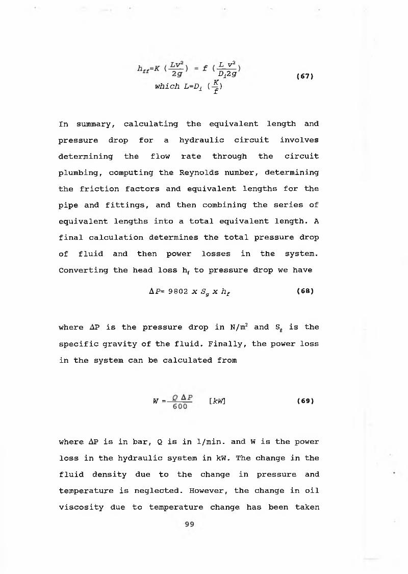
L v2
Dfig ( 6 7 )which L=Di (-^)
In summary, c a l c u l a t i n g t h e e q u i v a l e n t l e n g t h and
p r e s s u r e drop f o r a h y d r a u l i c c i r c u i t i n v o l v e s
d e t e r m in in g t h e f lo w r a t e th r o u g h t h e c i r c u i t
p lu m b in g , com p u tin g t h e R e y n o ld s number, d e te r m in in g
t h e f r i c t i o n f a c t o r s and e q u i v a l e n t l e n g t h s f o r t h e
p ip e and f i t t i n g s , and t h e n co m b in in g t h e s e r i e s o f
e q u i v a l e n t l e n g t h s i n t o a t o t a l e q u i v a l e n t l e n g t h . A
f i n a l c a l c u l a t i o n d e te r m in e s t h e t o t a l p r e s s u r e drop
o f f l u i d and t h e n power l o s s e s i n t h e sy s te m .
C o n v e r t in g t h e head l o s s hf t o p r e s s u r e drop we have
w here AP i s t h e p r e s s u r e drop i n N/m2 and Sg i s t h e
s p e c i f i c g r a v i t y o f t h e f l u i d . F i n a l l y , t h e power l o s s
i n t h e s y s te m can be c a l c u l a t e d from
w here AP i s i n b a r , Q i s i n 1 /m in . and W i s t h e power
l o s s i n t h e h y d r a u l i c s y s te m i n kW. The ch a n g e i n t h e
f l u i d d e n s i t y due t o t h e change i n p r e s s u r e and
t e m p e r a tu r e i s n e g l e c t e d . However, t h e ch an ge in o i l
v i s c o s i t y due t o te m p e r a tu r e ch an ge h a s b een ta k e n
AP= 9 802 x Sg x hf ( 68 )
W =— [kW] ( 6 9 )

i n t o a c c o u n t . Based on an e m p ir ic a l r e l a t i o n s h i p
b etw een t h e k in e m a t ic v i s c o s i t y and f l u i d t e m p e r a tu r e
a s r e p o r t e d by M ccoul e t a l (52) under t h e a tm o s p h e r ic
p r e s s u r e i t i s e x p r e s s e d a s :
v = e 1 0 e 1 0 ^ - B- '°3 < t *273l l + c| _ 7
w here c o n s t a n t s A and B depend on t h e t y p e o f f l u i d .
The e m p ir i c a l v a l u e s o f c o n s t a n t s A and B h a v e b een
u se d i n t h e p a ck a g e on t h e b a s i s o f e x p e r im e n t a l d a ta
o b t a in e d from R e f . (53)
3.11. Numerical Technique for Temperature Calculation in
Hydraulic System:
A f i r s t o r d e r E u le r i n t e g r a t i o n t e c h n iq u e p r e v i o u s l y
a p p l i e d in r e f e r e n c e s (5 4 -5 6 ) h a s b een u se d f o r
c a l c u l a t i n g t r a n s i e n t f l u i d t e m p e r a tu r e . T h is
t e c h n iq u e f o r te m p e r a tu r e c a l c u l a t i o n s was d e v e lo p e d
b a se d on t h e f a c t t h a t t h e t e m p e r a tu r e l e v e l s change
r e l a t i v e l y s lo w l y i n any h y d r a u l i c s y s te m and t h e
r e l e v a n t f l u i d p r o p e r t i e s can be r e g a r d e d a s c o n s t a n t
o v e r a p e r io d o f t im e w i t h o u t s i g n i f i c a n t l o s s o f
a c c u r a c y . The t e m p e r a tu r e t r a n s i e n t e q u a t io n s a re
s o l v e d by u s i n g f i r s t o r d e r E u le r i n t e g r a t i o n , t h e
t e m p e r a tu r e s a r e assum ed t o be c o n s t a n t f o r a f i x e d
s h o r t p e r io d o f t im e and th e n a r e u p d a te d . I f t h e
s i m u l a t i o n t im e e x c e e d s t h e c o n s t a n t te m p e r a tu r e
p e r i o d , t h e f l u i d and p ip e w a l l t e m p e r a tu r e s g i v e n by
100
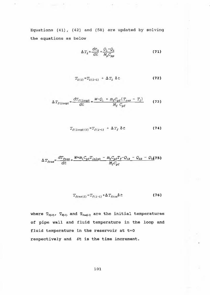
E q u a t io n s (41) , (42) and (58) a r e u p d ated by s o l v i n g
t h e e q u a t io n s a s below
A7-2 = ^ 2 = ^ ^ ( 7 1 )dt M„C„
+ AT, 6 1 ( 7 2 )
A rr, _ d T f ( i OOP) _ ^ Q\ + ̂̂ r e s Tf) f 7 3 \d i 1 ’
T f( lo o p ) (i) = T f ( i - l ) + A T f 6 t ( 7 4 )
A r _ dTfreg _ ̂ +̂ C pfTlnlet m2 CpfTf Qxr - Q2R 0ìi75)’ " ‘V i ,
T f r e S{ i ) = T f U - i ) + ^ f z 0 3 ò t ( 7 6 )
where T2(M)/ Tf(H) and Tfres(i4) are the initial temperatures
of pipe wall and fluid temperature in the loop and fluid temperature in the reservoir at t=0 respectively and fit is the time increment.
101

3.12. Computer Aided Design and Simulation of Fluid Power
Systems: D i g i t a l s im u l a t i o n f o r f l u i d power e n g i n e e r s
i s an e x t r e m e ly p o w e r fu l d e s ig n t o o l . A s y s te m or
com ponent can be t e s t e d a t a v e r y e a r l y s t a g e and a
bad s o l u t i o n can be e a s i l y abandoned . F u rth erm ore,
d e s i g n e r s a r e en co u ra g ed t o t r y new and u n o rth o d o x
s o l u t i o n s s i n c e t h e s e can be e v a l u a t e d a t a low c o s t .
M a in ly , t h e m a th e m a t ic a l m o d e ls h ave b een d e v e lo p e d t o
p r e d i c t t h e t r a n s i e n t f l u i d and p ip e w a l l te m p e r a tu r e
o f any h y d r a u l i c s y s t e m . T h is program can be
c o n s id e r e d a s a g e n e r a l s i m u l a t i o n program e s p e c i a l l y
s u i t e d t o s im u l a t e f l u i d power s y s t e m s . The
fu n d a m en ta l a im s o f t h i s programme a r e :
1 - To p r o v id e a c o m p u ta t io n a l t o o l w h ich can be u se d
by an i n d u s t r i a l e n g in e e r o r r e s e a r c h e r w i t h l i t t l e or
no k n o w led g e o f com puter s y s t e m s .
2 - To p r o v id e a f a c i l i t y w h ich a l l o w s c h a n g e s in
com ponent p a r a m e te r s o r i n c i r c u i t c o n f i g u r a t i o n t o be
c a r r i e d o u t w i t h o u t f u r t h e r n eed f o r program ming.
3 - To p r o v id e a f a c i l i t y w hich a l l o w s a d d in g new
com ponents w i t h o u t any m o d i f i c a t i o n i n t h e programme.
4 - To a l l o w s im p le n u m e r ic a l e x a m in a t io n o f t h e
b e h a v io u r o f s e l e c t e d c i r c u i t p a r a m e te r s .
102

T h is program may be u se d e i t h e r a t t h e d e s ig n s t a g e ,
w here t h e d e s ig n o f a p r o p o se d h y d r a u l i c s y s te m i s
i n v e s t i g a t e d o r e l s e f o r a s y s te m a lr e a d y in
o p e r a t i o n .
T h is program c o n s i s t s o f t h e f o l l o w i n g p a r t s :
1-The first part c o n t a in s d e t a i l e d s p e c i f i c a t i o n o f
pumps and h y d r a u l i c a c t u a t o r s i n c l u d i n g t o r q u e , s p e e d ,
power and e f f i c i e n c y .
2 - The steady state flow analysis program: T h is p a r t
p r e d i c t s t h e s t e a d y s t a t e f l o w s and p r e s s u r e s i n t h e
h y d r a u l i c s y s t e m , d e te r m in e s t h e f lo w r a t e th r o u g h t h e
c i r c u i t and, w h eth er f lo w i s la m in a r , t r a n s i t i o n a l o r
t u r b u l e n t in o r d e r t o a p p ly a p p r o p r ia t e r e s i s t a n c e
f a c t o r s . T h is p a r t can c a l c u l a t e t h e e q u i v a l e n t l e n g t h
o f t h e s y s te m and th e n d e te r m in e e i t h e r t o t a l p r e s s u r e
drop o r f l u i d h o rsep o w er l o s s r e s u l t i n g from t h e
f r i c t i o n o f t h e t o t a l e q u i v a l e n t l e n g t h . O ther f a c t o r s
su c h a s t h e v e l o c i t y a t s u c t i o n l i n e becom es e v i d e n t ,
and p i p e s can be r e s i z e d a s r e q u ir e d t o l i m i t
v e l o c i t i e s a t c r i t i c a l p l a c e s i n t h e c i r c u i t .
3-Power losses: T h is p a r t c a l c u l a t e s t h e power l o s s e s
i n t h e s y s te m i n c l u d i n g t h e power l o s s i n pump,
h y d r a u l i c m o to r , f i t t i n g and p i p e s .
4 - The hydraulic transient thermal analysis: T h is p a r t
p r e d i c t s t h e f l u i d t e m p e r a tu r e i n t h e s y s te m lo o p and
p ip e w a l l and r e s e r v o i r t e m p e r a tu r e s under u n s te a d y
c o n d i t i o n . I t a l s o p r e d i c t s t h e e f f e c t s o f s y s te m h e a t
g e n e r a t i o n on t h e p er fo rm a n ce o f an i n d u s t r i a l
103
h y d r a u l i c s y s te m .
3.12.1. Simulation Diagram: F ig (30) show s t h e c o m p le te
sy s te m s i m u l a t i o n d iagram f o r t h e dynam ic and th erm a l
s i m u l a t i o n o f open h y d r a u l i c s y s t e m s . The b lo c k HP
r e p r e s e n t s t h e s u b r o u t in e f o r t h e pump w hich
d e t e r m in e s t h e f l o w r a t e and in p u t t o r q u e t o t h e pump
and t h e e f f i c i e n c i e s . The h y d r a u l i c m otor i s s im u la te d
by t h e m odel HM w h ich g i v e s t h e t o r q u e a t t h e o u tp u t
s h a f t o f t h e m o to r , t h e s p e e d , t h e t o t a l f l u i d f lo w
l o s t from s l i p p a g e in t h e h ig h p r e s s u r e p o r t and t h e
m otor e f f i c i e n c i e s . The h y d r a u l i c r e s e r v o i r i s
m o d e lle d by b lo c k HR. The h y d r a u l i c dynam ic
p e r fo rm a n ce o f t h e s y s te m h a s b een m o d e l le d by b lo c k
DM th r o u g h s u b r o u t in e s HC ( h y d r a u l i c c i r c u i t m o d e l ) .
T h is s u b r o u t in e p r e d i c t s t h e p r e s s u r e s i n t h e s y s te m ,
t h e v e l o c i t y o f f lo w i n e a c h d i f f e r e n t d ia m e te r o f t h e
s y s t e m , w h e th e r f lo w i s la m in a r , t r a n s i t i o n a l or
t u r b u l e n t i n o r d e r t o a p p ly a p p r o p r ia t e r e s i s t a n c e
f a c t o r s . In a d d i t i o n , t h i s s u b r o u t in e can c a l c u l a t e
t h e e q u i v a l e n t l e n g t h o f t h e s y s te m and t h e n d e te r m in e
e i t h e r t o t a l p r e s s u r e drop o f f l u i d h o rsep o w er
r e s u l t i n g from t h e f r i c t i o n o f t h e t o t a l e q u i v a l e n t
l e n g t h . H owever, t h e power l o s s e s i n a l l com ponents
a r e summed in t h e model W^, . The power l o s s e s in t h e
p i p e s r e s u l t i n g from f r i c t i o n i s r e p r e s e n t e d i n b lo c k
Wpipos, w h i l e t h e power l o s s e s in t h e pump, h y d r a u l i c
104

m otor and f i t t i n g s a r e r e p r e s e n t e d i n b l o c k s Wpump
Wmotor and r e s p e c t i v e l y . The o u t s i d e w a l l
t e m p e r a tu r e o f t h e v e r t i c a l and a t t h e b ottom w a l l o f
t h e r e s e r v o i r a r e r e p r e s e n t e d i n m o d e ls Twrb and Twrv
r e s p e c t i v e l y . The m odel Twal, r e p r e s e n t s t h e o u t s i d e w a l l
te m p e r a tu r e o f p i p e s . The te m p e r a tu r e o f f l u i d in t h e
r e s e r v o i r and lo o p a r e r e p r e s e n t e d by Tfrcs and Tfloop
r e s p e c t i v e l y .
3.12.2. Data Acquisition for Simulation: a number o f
s i m u l a t i o n s h a v e b een c a r r i e d o u t t o p r e d i c t t h e
c h a n g e s i n s y s te m te m p e r a tu r e due t o t h e therm odynam ic
and h e a t t r a n s f e r p r o c e s s e s i n t h e s y s t e m . On t h e
b a s i s o f t h e e x p e r im e n ta l t e s t r i g d e s c r i b e d in
s e c t i o n ( 2 .3 ) and ( 2 . 5 ) , t h e u s e r d e f i n e d p a r a m e te r s
f o r e a c h m odel i n t h e s i m u l a t i o n b lo c k d iagram in F ig .
(3 0) h a v e b een o b t a in e d . The d e t a i l s o f t h e s e
p a r a m e te r s a r e l i s t e d i n T a b le (21) t o (47) .
S im u la t io n s w ere c a r r i e d o u t f o r a n a l y z i n g 60 m in u te
d u r a t io n e x p e r im e n ta l t e m p e r a tu r e t e s t d u r in g t h e
s y s te m l o a d i n g . In t h i s s i m p l i f i e d ap p roach f o r t h e
t e m p e r a tu r e s i m u l a t i o n t h e h y d r a u l i c s y s te m i s
r e g a r d e d a s an open th erm a l s y s t e m . The s y s te m i s a l s o
c o n s id e r e d t o be c o n s t r u c t e d by t h e same s i z e o f p i p e s
and p i p e w a l l m a t e r i a l w i t h an u n ifo rm f l u i d
te m p e r a tu r e th r o u g h o u t t h e s y s te m lo o p and r e s e r v o i r .
B ased on t h e e x p e r im e n ta l t e s t r i g , t h e h ig h p r e s s u r e
and r e t u r n l i n e s a r e ta k e n a s 0 .7 5 in c h (19 mm)
105

i n t e r n a l b o r e s i n g l e w ir e d h y d r a u l i c h o s e s and t h e
e x t e r n a l d ia m e te r o f t h e h o s e i s m easured a s 29 mm.
The t o t a l l e n g t h o f t h e p i p e s i s t a k e n a s 7 m. The
s u c t i o n l i n e h a s 1 .5 in c h ( 3 8 .1 mm) i n t e r n a l d ia m e te r
and t h e e x t e r n a l d ia m e te r o f t h e h o s e s u c t i o n l i n e i s
m easured a s ( 4 7 .5 mm). The t o t a l l e n g t h o f s u c t i o n
l i n e i s t a k e n a s 1 .5 m. The t y p e o f o i l u se d i n t h e
s i m u l a t i o n i s SHELL TELLUS-37.
U s in g t h e d a ta p r o v id e d in T a b le (17) and ( 1 8 ) , t h e
s p e c i f i c h e a t and th e r m a l c o n d u c t i v i t y f o r o i l , a r e
t a k e n a s 1964 (J/K g.K ) and 0 .1 4 4 (W/m. °C)
r e s p e c t i v e l y . F ig (12) shows a t y p i c a l s i n g l e w ir e
b r a id h y d r a u l i c h o s e c o n s t r u c t e d by s y n t h e t i c ru b b er
t u b e , s i n g l e b r a id r e in f o r c e m e n t and s y n t h e t i c ru b b er
c o v e r . The s p e c i f i c h e a t and th e r m a l c o n d u c t i v i t y o f
su c h a h o s e h a s b een ta k e n a s i f i t was made from pure
r u b b e r , i e 2010 (J/K g.K ) and ( 0 .0 1 3 W/m °C) . The
d e n s i t y o f p u re ru b b er 1100 (Kg/m3) h a s b een o b t a in e d
from t h e d a ta ta k e n from R ef ( 4 1 ) . The e m i s s i v i t y o f
t h e h o s e i s ta k e n a s t h e v a l u e o f n a t u r a l b la c k
r u b b e r , i e 0 . 9 . The d a ta i n T a b le (34) f o r i n i t i a l
f l u i d , p i p e w a l l and su r r o u n d in g a i r t e m p e r a tu r e s
b e f o r e t h e s y s te m lo a d in g h a v e b een e v a lu a t e d from
c o n s i d e r a t i o n o f e x p e r im e n ta l and t e s t c o n d i t i o n s .
3.12.3. Simulation Results and Discussion: u s i n g t h e in p u t
d a ta d e f i n e d a b o v e , t h e s i m u l a t i o n s u s i n g F ig . (30)
h a v e b een c a r r i e d o u t t o p r e d i c t t h e t h e o r e t i c a l f l u i d

and p ip e w a l l t e m p e r a tu r e s in t h e s y s t e m , and a l s o t o
i n v e s t i g a t e t h e e f f e c t s o f v a r i o u s p a r a m e te r s on t h e
sy s te m p er fo rm a n ce i n d i c a t e d by t h e l e v e l o f
te m p e r a tu r e In t h e s e s i m u l a t i o n s , t h e e l e c t r i c motor
was r u n n in g s t e a d i l y a t 1500 r .p .m .
A c c o r d in g t o t h e m a th e m a t ic a l m odel o f t h e sy s te m
therm odynam ic p r o c e s s , t h e f l u i d and p ip e w a l l
t e m p e r a tu r e s o f t h e s y s te m s h o u ld be a f f e c t e d by a
number o f p a r a m e t e r s . A c l e a r a p p r e c i a t i o n can be
o b t a in e d from a c l o s e e x a m in a t io n o f a r a n g e o f
s im u l a t i o n r e s u l t s w i t h i t s g o v e r n in g e q u a t io n s . The
a n a l y s i s o f f l u i d and p ip e w a l l t e m p e r a tu r e s in t h e
open h y d r a u l i c d r i v e m ix er s y s te m i s g iv e n a s an
ex a m p le . S i m i l a r a n a l y s i s can be c o n s id e r e d t o exam ine
f l u i d and p ip e w a l l t e m p e r a tu r e r e s u l t s in t h e o th e r
sy s te m s i m u l a t i o n s .
The power l o s s o f t h e com ponents d u r in g t h e sy s te m
l o a d in g i s t h e o n ly h e a t g e n e r a t i o n s o u r c e t o c a u s e
t h e i n c r e a s e o f f l u i d t e m p e r a tu r e i n t h e h y d r a u l i c
s y s t e m s . F ig (31) shows t h e e f f e c t s o f power l o s s e s on
t h e f l u i d t e m p e r a tu r e , t h i s f i g u r e shows t h e i n c r e a s e
i n t h e s im u la t e d f l u i d t e m p e r a tu r e i n r e s p o n s e t o t h e
i n c r e a s e o f t h e t o t a l power l o s s i n t h e s y s t e m . In
t h i s s p e c i f i c c a s e o f t h e s y s te m s i m u l a t i o n , when t h e
power l o s s e x c e e d s t h e v a l u e o f 160 W a tts , t h e f l u i d
te m p e r a tu r e i n t h e lo o p w i l l r i s e above t h e
recommended maximum f l u i d te m p e r a tu r e 60 °C. In o r d e r
t o e n s u r e an a p p r o p r ia t e p er fo rm a n ce o f t h e s y s t e m , a
107

c o o l e r i s n eed ed t o be in c o r p o r a t e d i n t h e sy s te m when
t o t a l sy s te m power l o s s i s h ig h e r th a n 160 W a tts .
T h ese s im u la t e d r e s u l t s h ave shown t h a t f l u i d
t e m p e r a tu r e s h a v e two d i s t i n c t r a t e s o f i n c r e a s e :
un d er t h e s i m u l a t i o n c o n d i t i o n d e f i n e d , a f a s t
i n c r e a s e i s shown w i t h in t h e f i r s t h a l f an hour o f t h e
s y s te m l o a d i n g , d u r in g t h e se c o n d h a l f o f t h e sy ste m
l o a d i n g , t h e r a t e o f i n c r e a s e in f l u i d te m p e r a tu r e i s
much s lo w e r . S i m i l a r l y , F i g . (32) s u g g e s t s t h a t t h e
i n c r e a s e in power l o s s e s h a s a s i g n i f i c a n t e f f e c t on
t h e p ip e w a l l t e m p e r a tu r e w hich i n c r e a s e f o l l o w i n g t h e
same p a t t e r n a s f o r t h e f l u i d t e m p e r a tu r e .
I t h a s b een p o i n t e d o u t t h a t t h e f l u i d te m p e r a tu r e i s
a l s o d e p e n d e n t on t h e f l u i d m ass Mf and h e a t
d i s s i p a t e d th r o u g h t h e p i p e l i n e o f t h e s y s te m When
t h e t o t a l p ip e l e n g t h o f t h e sy s te m i s ch a n g ed , Qj due
t o t h e c o r r e s p o n d in g ch an ge in t h e p i p e i n t e r n a l
s u r f a c e a r e a and Mf w i l l be a f f e c t e d and s o t h e f l u i d
te m p e r a tu r e a l s o c h a n g e s .
The s i m u l a t i o n r e s u l t s in F ig . (3 3) show s t h e e f f e c t s
o f t h e p ip e l e n g t h on f l u i d t e m p e r a tu r e and F ig . (34)
show s t h e e f f e c t o f t h e p ip e l e n g t h on t h e o u t s i d e
h o s e w a l l t e m p e r a tu r e . T h ese f i g u r e s d e m o n s tr a te t h a t
when t h e t o t a l p i p e l e n g t h i s i n c r e a s e d , t h e f l u i d and
o u t s i d e w a l l t e m p e r a tu r e s o f t h e h o s e a r e a l s o
i n c r e a s e d . S i m i l a r l y , when t h e i n s i d e d ia m e te r o f p ip e
i s ch a n g ed , t h e f l u i d m ass Mf in t h e p ip e l i n e i s
ch a n g ed , h e n c e t h e f l u i d te m p e r a tu r e w ou ld be a f f e c t e d
108
a s s u g g e s t e d in t h e s i m u l a t i o n r e s u l t s in F i g . ( 3 5 ) .
S i m i l a r l y , t h e ch an ge in t h e i n t e r n a l p ip e d ia m e te r
show s i n f l u e n c e on t h e o u t s i d e p ip e w a l l te m p e r a tu r e
a s shown i n F i g . (36) . The s i z e o f t h e p ip e o u t s i d e
d ia m e te r h a s more s i g n i f i c a n t i n f l u e n c e on t h e p ip e
w a l l t e m p e r a tu r e a s shown in F ig . (37) T h is i s b e c a u se
t h e o u t s i d e s u r f a c e a r e a o f t h e p i p e w a l l i s a
dom inant f a c t o r i n d e te r m in in g t h e h e a t f lo w
t r a n s f e r r e d from t h e o u t s i d e p ip e w a l l t o a tm o sp h ere .
The f l u i d t e m p e r a tu r e i s n o t much a f f e c t e d by t h e
v a r i a t i o n o f t h e o u t s i d e p ip e d ia m e t e r , s i n c e t h e
o u t s i d e p ip e d ia m e te r h a s l i t t l e e f f e c t s on t h e h e a t
f lo w t r a n s f e r r e d from t h e f l u i d t o t h e i n s i d e p ip e
w a l l , Qj. The s i m u l a t i o n r e s u l t s o f t h e e f f e c t s o f th e
v a r i a t i o n o f t h e o u t s i d e p ip e d ia m e te r on f l u i d
t e m p e r a tu r e i s show i n F ig . ( 3 8 ) .
The t y p e o f t h e p ip e w a l l m a t e r i a l p l a y s an im p o r ta n t
r o l e i n d e t e r m in in g t h e te m p e r a tu r e d i s t r i b u t i o n ,
s i n c e t h e v a l u e s o f s p e c i f i c h e a t , d e n s i t y and th erm a l
c o n d u c t i v i t y a r e d ep en d a n t on t h e p ip e w a l l m a t e r i a l .
As e x p r e s s e d in E q u a tio n ( 3 5 ) , t h e h e a t t r a n s f e r r e d
w i t h i n t h e p ip e w a l l by c o n d u c t io n i s a f f e c t e d by t h e
th e r m a l c o n d u c t i v i t y k o f t h e p ip e w a l l m a t e r i a l . F ig .
(39) show s t h e e f f e c t o f th e r m a l c o n d u c t i v i t y o f th e
p i p e w a l l m a t e r i a l on f l u i d t e m p e r a t u r e . The r e s u l t s
show t h a t t h e r e d u c t i o n o f t h e v a l u e o f k w i l l
i n c r e a s e f l u i d t e m p e r a tu r e i n t h e lo o p due t o
109
c o r r e s p o n d in g r e d u c t i o n in Qj. S i m i l a r l y , t h e v a l u e o f
p i p e w a l l k h a s c o n s i d e r a b l e i n f l u e n c e on t h e o u t s i d e
p i p e w a l l t e m p e r a tu r e a s shown in t h e s im u l a t i o n
r e s u l t s i n F i g . ( 4 0 ) . The s p e c i f i c h e a t o f p ip e w a l l
m a t e r i a l a f f e c t s t h e r a t e o f i n c r e a s e i n t h e p i p e w a l l
te m p e r a tu r e a s i n d i c a t e d i n E q u a t io n (42) . T h is e f f e c t
i s w e l l r e f l e c t e d in t h e s i m u l a t i o n r e s u l t s shown in
F i g . (41) . S in c e f l u i d te m p e r a tu r e d i s t r i b u t i o n i s
a f f e c t e d by t h e p ip e w a l l t e m p e r a t u r e s , F i g . (42) shows
a s i m i l a r ch a n g e on f l u i d t e m p e r a tu r e w i t h t h e
v a r i a t i o n o f t h e p ip e w a l l s p e c i f i c h e a t . For t h e same
r e a s o n , t h e m ass or d e n s i t y o f t h e p i p e w a l l has
i n f l u e n c e on t h e p ip e w a l l and f l u i d t e m p e r a tu r e s a s
shown in F ig . (43) and (44) r e s p e c t i v e l y w h ich show
s i m i l a r t r e n d s a s t h o s e in F ig s (41) and ( 4 2 ) .
The d i f f e r e n c e b e tw een t h e p ip e w a l l o u t s i d e and
s u r r o u n d in g a tm o s p h e r ic t e m p e r a tu r e s i s g r e a t l y
i n f l u e n c e d by t h e e f f e c t s o f p ip e w a l l h e a t r a d i a t i o n
a s e x p r e s s e d i n E q u a t io n (38) by t h e e m i s s i v i t y o f th e
p i p e w a l l m a t e r i a l e . T h is i s due t o t h e h e a t f lo w
t r a n s f e r r e d from o u t s i d e p ip e w a l l t o i t s s u r r o u n d in g
a tm o sp h ere by t h e n a t u r a l c o n v e c t i o n and r a d i a t i o n .
The r a d i a t i o n e f f e c t can be a s im p o r ta n t a s t h e
n a t u r a l c o n v e c t i o n when t h e h e a t t r a n s f e r c o e f f i c i e n t
by n a t u r a l c o n v e c t i o n ha i s r e l a t i v e l y s m a l l . The
e f f e c t s o f t h e e m i s s i v i t y o f t h e p ip e w a l l m a t e r i a l on
t h e p ip e w a l l and f l u i d t e m p e r a tu r e s a r e d e m o n str a te d
i n t h e s i m u l a t i o n r e s u l t s shown i n F i g . (45) and F ig .
110
(46) r e s p e c t i v e l y .
r e p l a c e d by t h e commonly u se d m ild s t e e l o r co p p er
p i p e s , t h e in p u t s i m u l a t i o n d a ta in T a b le (34) w i l l be
ch an ged t o t h e d a ta in T a b le (35) o r (36)
r e s p e c t i v e l y . A l a r g e d i f f e r e n c e b e tw e e n t h e o u t s i d e
p ip e w a l l t e m p e r a tu r e s o f s t e e l o r c o p p e r p i p e s and
ru b b er h o s e i s shown in s im u l a t i o n r e s u l t s i n F ig (47)
and (48) a s i t w ou ld be e x p e c t e d due t o a b ig
d i f f e r e n c e b e tw een t h e th e r m a l c o n d u c t i v i t i e s o f
m e t a l l i c and n o n - m e t a l l i c m a t e r i a l s a s s u g g e s t e d in
T a b le (35) ( f o r s t e e l k=60 W/m.K; c o p p e r : k=386
W/m.K; ru b b er: k = 0 .0 1 3 W/m.K). An i n t e r e s t i n g
phenomenon shown in t h e s im u l a t i o n f l u i d te m p e r a tu r e s
i n F i g s . (47) a n d (48) i s t h a t f l u i d te m p e r a tu r e i n t h e
s y s te m w i t h t h e s t e e l o r co p p er p i p e l i n e i s h ig h e r
th a n i t in t h e s y s t e m w ith t h e h y d r a u l i c h o s e . T hese
s i m u l a t i o n f l u i d t e m p e r a tu r e s h ave r e s u l t e d when t h e
e f f e c t s o f r a d i a t i o n and c o n d u c t io n a r e ta k e n i n t o
a c c o u n t . D e s p i t e t h e f a c t t h a t t h e th erm a l
c o n d u c t i v i t i e s o f s t e e l and co p p er p i p e s a r e much
h ig h e r th a n t h a t o f ru b b er h o s e , t h e e m i s s i v i t y o f
s t e e l and co p p er a r e lo w e r th a n o f ru b b er h o s e a s d a ta
i n d i c a t e d i n T a b le (15) ( f o r m ild s t e e l e = 0 .3 2 ;
p o l i s h e d co p p er : e = 0 .0 1 8 ; ru b b er: e = 0 . 9 4 ) . T h is
co m p a r iso n o f s i m u l a t i o n f l u i d t e m p e r a tu r e r e s u l t s
s h o u ld q u e s t i o n t h e w id e ly a c c e p t e d a s su m p t io n in many
I f t h e h y d r a u l i c h o s e p i p e l i n e i n t h e s y s t e m i s
111

t e x t book s w h ich ig n o r e t h e r a d i a t i o n e f f e c t under
200 °C.
F u r th e r m ore, F i g s (49) and (50) show t h e com p arison
o f t h e e f f e c t s o f h e a t t r a n s f e r p r o c e s s e s . In t h e s e
F ig u r e s t h e e f f e c t s o f c o n v e c t i o n , c o n d u c t io n and
r a d i a t i o n i n t h e lo o p and t h e r e s e r v o i r h ave been
ta k e n i n t o a c c o u n t . T h ese s im u la t e d r e s u l t s show t h a t
by i g n o r in g t h e e f f e c t o f r a d i a t i o n from th e
r e s e r v o i r , t h e t r a n s i e n t te m p e r a tu r e in t h e h y d r a u l i c
s y s t e m w ould be 2 . 5 °C t o 3 .5 °C h ig h e r i n t h e sy ste m
w h ich c o u ld g i v e r i s e t o e r r o r in e s t i m a t i n g th e
t e m p e r a tu r e d i s t r i b u t i o n i n h y d r a u l i c s y s t e m s .
3.13. Temperature Simulations Results for the Reservoir in
the Open Hydraulic Drive Mixer System: a r e s e r v o i r i s
r e q u ir e d in t h e m a j o r i t y o f h y d r a u l i c s y s t e m s . When i t
i s u s e d , t h e h y d r a u l i c s y s te m no lo n g e r can be
c o n s id e r e d a s a c l o s e d th e r m a l s y s te m b e c a u s e th e
ex c h a n g e o f t h e f lo w e n e r g i e s o f t h e f l u i d s i n t h e
l o o p and i n t h e r e s e r v o i r . An a n a l y t i c a l m odel h as
b een d e v e lo p e d i n S e c t i o n ( 3 .7 ) and ( 3 . 8 ) . The
p r i n c i p l e o f t h e m odel i s t o c o n s id e r t h e h y d r a u l i c
s y s t e m a s two open th e r m a l s y s t e m s ; t h e lo o p and th e
r e s e r v o i r . An a s su m p t io n h a s b een made t o r e g a r d t h e
t e m p e r a t u r e s o f t h e f l u i d s in t h e lo o p and r e s e r v o i r
a s tw o s e p a r a t e u n ifo r m v a l u e s . The com puter program
d e v e lo p e d f o r p r e d i c t i n g t h e s e two f l u i d t e m p e r a tu r e s
112

can be u s e d f o r s i m u l a t i o n o f t h e open h y d r a u l i c d r i v e
m ix er s y s te m .
A number o f s i m u l a t i o n s h a v e b een c a r r i e d o u t t o
i n v e s t i g a t e t h e e f f e c t o f r e s e r v o i r g e o m etry on th e
lo o p f l u i d t e m p e r a tu r e .
The f l u i d h e i g h t in t h e r e s e r v o i r d e t e r m in e s t h e
v e r t i c a l s i d e a r e a s o f t h e r e s e r v o i r (A2 and A3) . a s
i n d i c a t e d i n E q u a t io n s (44) and (50) , t h e amount o f
h e a t f lo w d i s s i p a t e d th r o u g h t h e r e s e r v o i r s i d e w a l l s
Q1r i s a f f e c t e d by t h e s e a r e a s o f t h e r e s e r v o i r . T h is
v a l u e o f h e a t d i s s i p a t e d th r o u g h t h e s i d e w a l l s o f t h e
r e s e r v o i r w i l l a f f e c t f l u i d te m p e r a tu r e i n s i d e t h e
r e s e r v o i r a s e x p r e s s e d by E q u a t io n ( 5 8 ) . M oreover , t h e
f l u i d te m p e r a tu r e i n s i d e t h e r e s e r v o i r and i n t h e
s y s te m lo o p a r e d ep en d en t on ea ch o t h e r , so t h e change
in t h e f l u i d h e i g h t in t h e r e s e r v o i r w i l l r e s u l t in a
c o r r e s p o n d in g ch an ge i n t h e f l u i d te m p e r a tu r e in t h e
s y s te m lo o p . A c l e a r a p p r e c i a t i o n can be o b t a in e d from
a c o l l e c t i o n o f s i m u l a t i o n r e s u l t s i n F i g s (51) and
(53) w h ich show t h e e f f e c t s o f f l u i d h e i g h t in th e
r e s e r v o i r on t h e f l u i d and o u t s i d e h o s e w a l l
t e m p e r a t u r e s i n t h e s y s te m lo o p . T h ese f i g u r e s
s u g g e s t t h a t any ch an ge o f t h e f l u i d h e i g h t i n t h e
r e s e r v o i r w i l l n o t o n ly a f f e c t t h e m ass o f f l u i d in
t h e r e s e r v o i r , w h ich i s one o f t h e f a c t o r s t o
d e te r m in e t h e ch an ge r a t e o f t h e f l u i d t e m p e r a tu r e in
113
r e s e r v o i r , b u t a l s o ch a n g e t h e amount o f h e a t
d i s s i p a t e d th r o u g h t h e v e r t i c a l s i d e w a l l o f t h e
r e s e r v o i r . As a c o n s e q u e n c e , t h e s t e a d y l e v e l o f t h e
f l u i d te m p e r a tu r e in t h e r e s e r v o i r i s a l s o a f f e c t e d by
t h i s ch an ge o f t h e f l u i d h e i g h t , t h e s e f i g u r e s show
h ig h e r v a lu e o f Ht f o r lo w e r v a lu e o f t e m p e r a tu r e .
For t h e same r e a s o n , t h e s i z e o f t h e r e s e r v o i r b a se
h a s i t s i n f l u e n c e b o th on t h e f l u i d t e m p e r a tu r e o f t h e
r e s e r v o i r and t h e s y s te m l o o p . The s i m u l a t i o n r e s u l t s
i n F i g s . ( 5 3 ) and (54) and F i g s . (55) and (56) p r e d i c t
t h e e f f e c t s o f t h e l e n g t h and w id th o f t h e r e s e r v o i r
on t h e f l u i d and o u t s i d e h o s e w a l l t e m p e r a tu r e s in
t h e s y s te m lo o p r e s p e c t i v e l y . T h ese f i g u r e s a r e
d i f f e r e n t i n t r e n d from t h o s e i n F ig s (51) and (52)
w h ich i n d i c a t e t h a t t h e lo w e r t h e v a l u e s o f and S,
h i g h e r t h e v a l u e s o f t e m p e r a t u r e s . I t can b e s e e n t h a t
t h e w id th o f t h e r e s e r v o i r i s l e s s e f f e c t i v e th a n th e
h e i g h t and l e n g t h o f t h e b a s e o f t h e r e s e r v o i r on t h e
te m p e r a tu r e d i s t r i b u t i o n . M oreover , t h e s im u la t e d
r e s u l t s h ave shown t h a t t h e e f f e c t o f t h e t h i c k n e s s
and t y p e o f m a t e r i a l o f t h e r e s e r v o i r h a v e v e r y l i t t l e
i n f l u e n c e on t h e f l u i d and o u t s i d e h o s e w a l l
te m p e r a tu r e s a s shown i n F i g s . ( 5 7 ) , ( 5 8 ) , (59) and
(60) . The f l u i d t e m p e r a tu r e in t h e lo o p i s a l s o
a f f e c t e d by t h e v a lu e o f t h e f lo w r e t u r n i n g t o t h e
r e s e r v o i r a s e x p r e s s e d i n E q u a t io n (43) in term s o f
m ass f l o w r a t e mf. As a l r e a d y s t a t e d i n t h e t e m p e r a tu r e
114

analysis for an bpen hydraulic system (using ar e s e r v o i r ) , t h e w h o le h y d r a u l i c s y s te m can be
c o n s id e r e d a s a c o m b in a t io n o f two open th erm a l
s y s t e m s : t h e lo o p and t h e r e s e r v o i r . The en e r g y
t r a n s f e r b e tw een t h e lo o p and r e s e r v o i r th erm a l
s y s t e m s i s e x p r e s s e d i n E q u a t io n (43) i n term s o f mf
c Pf ( T res “ T f ) I w here t h e m ass f l o w r a t e mf = pQ, Tres i s
t h e u n ifo r m f l u i d te m p e r a tu r e i n t h e r e s e r v o i r , t h e
f i r s t term p Q Cpf Tres r e p r e s e n t s t h e f lo w e n e r g y
r e c e i v e d by t h e lo o p th e r m a l s y s te m w h i l e t h e seco n d
term p Q Cpf Tf i n d i c a t e s t h e f lo w e n e r g y from t h e lo o p
t o t h e r e s e r v o i r . The e f f e c t o f t h e r a t e o f t h e f lo w
b etw een t h e lo o p and r e s e r v o i r on t h e lo o p te m p e r a tu r e
i s d e m o n str a te d in t h e s i m u l a t i o n r e s u l t s i n F ig .
(61) . As can be s e e n , when no f lo w r e t u r n s t o t h e
r e s e r v o i r , t h e i n c r e a s e o f f l u i d te m p e r a tu r e in t h e
sy s te m lo o p d u r in g t h e s y s te m lo a d in g i s i d e n t i c a l t o
t h e f l u i d te m p e r a tu r e o f t h e open h y d r a u l i c d r i v e
m ix er s y s te m d i s c u s s e d i n t h e l a s t s e c t i o n . As t h i s
f l o w r a t e r i s e s , t h e f lo w e n e r g y t r a n s f e r r e d from t h e
s y s te m lo o p t o t h e r e s e r v o i r i n c r e a s e s and s o t h e lo o p
te m p e r a tu r e w i l l r e d u c e . M eanw hile , t h e lo o p f l u i d
t e m p e r a tu r e w i l l be a f f e c t e d by t h e r i s e o f t h e
r e s e r v o i r t e m p e r a tu r e due t o t h i s i n c r e a s e o f t h e
f lo w .
A n o th er f e a t u r e o f t h e s e te m p e r a tu r e r e s u l t s i s t h a t
when t h e f l o w r a t e r e t u r n i n g t o t h e r e s e r v o i r e x c e e d
115
a b o u t 0 . 5 1 /m in , t h e r e d u c t i o n o f t h e lo o p
t e m p e r a tu r e w i t h t h e i n c r e a s e o f t h e s y s te m f l o w r a t e
t o t h e r e s e r v o i r g r a d u a l l y becom es i n s i g n i f i c a n t . T h is
phenomenon may be e x p l a i n e d i n t h e f o l l o w i n g way: when
t h e f l o w r a t e c i r c u l a t i n g i n t h e r e s e r v o i r e x c e e d s a
v a l u e a t w h ich an e q u i l i b r i u m o f h e a t d i s s i p a t i o n
p r o c e s s i s e s t a b l i s h e d t h e v a lu e o f t h e h e a t
d i s s i p a t e d th r o u g h t h e p i p e s o f t h e s y s te m lo o p and
t h e v a l u e o f f lo w e n e r g y t r a n s f e r r e d t o t h e r e s e r v o i r
w i l l become c o n s t a n t . In t h i s c a s e , any f u r t h e r
i n c r e a s e o f t h e f l o w r a t e w i l l n o t a f f e c t t h e f i n a l
v a l u e o f t h e f lo w e n e r g y i n term s o f p Q Cpf (Tres - Tf )
b u t in t r o d u c e a s m a l l r e d u c t i o n i n t h e f l u i d
t e m p e r a tu r e d i f f e r e n c e b etw een t h e lo o p and t h e
r e s e r v o i r (Tres-Tf) . H ence, o n c e t h e e q u i l i b r i u m o f t h e
p r o p o r t io n o f h e a t d i s s i p a t e d th r o u g h t h e p i p e s o f t h e
lo o p and t h e r e s e r v o i r i s e s t a b l i s h e d , t h e lo o p
te m p e r a tu r e w i l l n o t be a f f e c t e d by any f u r t h e r
ch an ge i n t h e sy s te m f l o w r a t e r e t u r n i n g t o t h e
r e s e r v o i r a s i n d i c a t e d in F i g . ( 6 1 ) . F u rth erm ore , t h e
r a t e o f t h e h e a t d i s s i p a t e d th r o u g h t h e w a l l s o f th e
r e s e r v o i r w h ich i s c a l c u l a t e d u s i n g t h e r e s e r v o i r
t e m p e r a tu r e m a th e m a t ic a l m odel w i t h t h e d e f in e d
p a r a m e te r s o f t h e r e s e r v o i r s i z e , t o g e t h e r w i t h t h e
power l o s s and f lo w e n e r g y t r a n s f e r r e d from t h e lo o p
p Q Cpf(Tres-Tf) h ave r e s u l t e d t h e g r a d u a l f l u i d
t e m p e r a tu r e i n c r e a s e a s shown in F ig . ( 61 ) . When a l l
sy s te m f lo w r e t u r n s t o t h e r e s e r v o i r a s i n t h e open
116

h y d r a u l i c s y s te m , s i n c e t h e v a l u e s o f t h e f lo w en e r g y
and t h e h e a t d i s s i p a t i o n a r e t h e same w i t h t h e above
c a s e , t h e r i s e o f t h e power l e d t o a s m a l l i n c r e a s e in
t h e r e s e r v o i r f l u i d t e m p e r a tu r e .
The p r o p o r t io n o f h e a t d i s s i p a t i o n th r o u g h t h e lo o p
p i p e s i s e x p r e s s e d by SQj i n E q u a tio n (4 3) . For
i n s t a n c e , in t h e c a s e o f t h e open h y d r a u l i c d r i v e
m ix e r s y s t e m , t h e s i m u l a t i o n r e s u l t s o f t h e h e a t
d i s s i p a t e d th r o u g h t h e p i p e s i s shown i n F i g . (62) .
The r e s t o f t h e lo o p h e a t d i s s i p a t e d i n t h e r e s e r v o i r
h a s l e d t o a s m a l l d i f f e r e n c e b etw een t h e f l u i d
te m p e r a tu r e o f t h e lo o p and t h a t o f t h e r e s e r v o i r a s
shown i n co m p a r iso n o f t h e s e two te m p e r a tu r e s in F ig .
(62) . F i g . (63) shows t h e co m p a r iso n o f s im u la te d
r e s u l t s o f lo o p and r e s e r v o i r f l u i d t e m p e r a tu r e . T h is
f i g u r e i l l u s t r a t e s t h a t t h e h e a t t r a n s f e r by r a d i a t i o n
m ust be c o n s id e r e d t o g e t more a c c u r a t e r e s u l t s in
te r m s o f t h e t e m p e r a tu r e d i s t r i b u t i o n i n h y d r a u l i c
s y s t e m s . A f u r t h e r i n v e s t i g a t i o n i n t o t h e t e m p e r a tu r e
p er fo r m a n c e d u r in g t h e s y s te m l o a d in g may b e c a r r i e d
o u t by c o n s i d e r i n g a b i g i n c r e a s e i n t h e power l o s s t o
t h e v a l u e o f 12 00 W a tts . As shown in co m p a r iso n t o t h e
s i m u l a t i o n r e s u l t s f o r t h e f l u i d t e m p e r a tu r e i n t h e
lo o p and t h e r e s e r v o i r i n F ig . (64) , a l th o u g h t h e
i n c r e a s e in t h e power l o s s h a s i n c r e a s e d t h e r a t e o f
ch a n g e and s t e a d y v a lu e o f t h e f l u i d t e m p e r a tu r e s o f
t h e lo o p and t h e r e s e r v o i r , n e v e r t h e l e s s t h e
117

d i f f e r e n c e b e tw een t h e s e two f l u i d t e m p e r a tu r e s i s n o t
a s b i g a s i t o t h e r w i s e m ig h t h a v e b een e x p e c t e d .
From t h e a n a l y s i s o f t h e ab ove s i m u l a t i o n r e s u l t s , i t
h a s b een fou n d t h a t t h e h e a t d i s s i p a t i o n th r o u g h t h e
p i p e s o f a h y d r a u l i c s y s te m p l a y s an im p o r ta n t p a r t in
d e t e r m in in g t h e t e m p e r a tu r e d i s t r i b u t i o n s i n t h e lo o p
and t h e r e s e r v o i r . The a s su m p t io n w h ich i g n o r e s t h i s
v i t a l therm odynam ics and h e a t t r a n s f e r p r o c e s s e s
d u r in g t h e l o a d i n g o f a h y d r a u l i c s y s te m may l e a d t o
g r e a t e r e r r o r s in p r e d i c t i n g b o th t h e f l u i d
te m p e r a tu r e in t h e lo o p and t h a t in t h e r e s e r v o i r th a n
had b een p r e v i o u s l y t h o u g h t .
In o r d e r t o i n v e s t i g a t e t h e s e te m p e r a tu r e r e s u l t s
o b t a in e d by s i m u l a t i o n , a r a n g e o f e x p e r im e n t a l t e s t
h a s b een c a r r i e d o u t i n an open h y d r a u l i c d r i v e m ixer
s y s te m t o m easu re t h e f l u i d t e m p e r a tu r e o f t h e lo o p
and t h e r e s e r v o i r i n a d d i t i o n t o m e a su r in g te m p e r a tu r e
o f t h e p i p e s w a l l . The e x p e r im e n ta l te m p e r a tu r e
r e c o r d i n g s and t h e i r c o m p a r iso n s w i t h s im u l a t i o n
r e s u l t s w i l l b e d i s c u s s e d i n t h e f o l l o w i n g two
c h a p t e r s .
118

*formal Emissivity of Various Surfaces. . :
Surface T [°C] Emissivity e
Ir o n P o l i s h e d 4 2 5 -1 0 2 5 0 . 1 4 - 0 . 3 8
O x id iz e d 100 0 .7 7
C a st I r o n 22 0 .4 4
Rubber Hard 23 0 . 94
S o f t , g r e y 23 0 .8 6
S t e e l M ild S t e e l 4 5 -1 0 6 5 0 . 1 8 - 0 . 3 2
Copper P o l i s h e d 80 0 . 018
P o l i s h e d 100 0 .0 2 3
B la c k
O x id iz e d
37 0 .7 8
Water 0 -1 0 0 0 . 9 5 - 0 . 9 6
Table (15) Normal emissivity for several used material in
hydraulics taken from table (C-l) of ref. (41).
119

Type o f shap e h [W/m2 °C]
Laminar o r
T r a n s i t i o n
T u r b u le n t
H o r iz o n t a l
c y l i n d e r o f
D ia m eter d
104 < Gr <109 109<Gr<1012
h = l . 32 ( 0 / d ) 1/4 h = l .2 5 em
V e r t i c a l P l a t e o f
h e i g h t L, or
C y l in d e r o f L arge
D ia m e te r , d
104<Gr<109 109<Gr<1012
h = l . 42 ( 0 /L = d )1/4 h = l . 31 01/3
Square P l a t e 1 X
1: h e a t e d P l a t e
f a c i n g up or
C ooled P l a t e
f a c i n g Down
105< Gr < 2 x l 0 7 2 x l 0 7<Gr<3
x lO 10
h = l . 3 2 ( 0 / L ) 1/4 h = l .52 em
Square P l a t e 1 x
1: C o o led P l a t e
F a c in g up or
H eated P l a t e
F a c in g Down
3 x l 0 5 <Gr <
3 x l 0 10
h=0 . 59 (6 / L ) 1/4
Table(16) Simplified equations for free convection heat
transfer coefficients in air at atmospheric pressure taken
from Fig(22.17) ref. (42)
120

Specific Heat of Several Material
M a t e r ia l T [°C] S p e c i f i c H eat
[K J/K g.°C ]
I r o n Pure 20 0 .4 5 2
Wrought
5% C
20 0 .4 6
S t e e l Carbon
C«1.5%
20 0 .4 8 6
M ild 20 0 .4 8 7
Chrome 20 0 .4 5 2
Copper Pure 20 0 .3 8 3 1
Rubber 30 2 .0 1 0
M achine O i l 40 1 .9 6 4
Water 40 4 .1 7 8 4
Sand 30 0 .8 0 0
Table (17) Specific heat for several used material in
hydraulics system taken from tables (B-4) and (B-5)
of ref (41)
121

Thermal Conductivity of Several Surfaces: .............. .. . ¿till . . : '
M a t e r ia l T [°C] Thermal
C o n d u c t iv i t y k
[W/m. °C]
I r o n Pure 20 73
100 76
300 55
Wrough
t 0.5%
C
20 59
S t e e l Carbon
1 .5 %
20 36
Chrome 20 61
M ild 40 60
Copper Pure 20 386
100 379
Rubber S o f t 30 0 . 012
Hard 30 0 .0 1 3
M achine O i l 40 0 . 144
Water 40 0 . 628
Tale (18) Thermal conductivity for several used materials in
hydraulic system taken from tables (B-4) and (B-5) of Ref.
(41)
122

Absolute Roughness of Several Surfaces; | \ ■' ‘ ” | ' ' . ! . " ! . . . . • - ■ • - ;: ■ ... . '■ '■ :: : : :: ; ; : : ! : : ■ . i : : ; : -----.. . . .. . ....... . ..... .... .. ..
M a t e r ia l R oughness s U n it
Drawn Tubing 0 .0 0 0 0015 m
S t e e l P ip e 0 .0 0 0 046 m
G a lv a n iz e d Ir o n 0 .0 0 0 2 m
C a st I r o n 0 .0 0 0 26 m
Rubber 0 .0 0 0 30 t o
0 .0 0 3 0
m
Table (19) Absolute roughness of commercially pipe and
tubing taken from ref. (46)
123

Density of Several Material' • ■ ■ ■ ' ■ •> ■ . ' ' : 1 .V:: :: . . • ; ■ :: : ''''' " ••-••• ..■ •- ;
M a t e r ia l T [ °C] P [Kg/m3]
I r o n Pure 20 7897
Wrought
0.5% C
20 7849
S t e e l M ild 30 7833
Rubber S o f t 30 1100
Hard 30 1190
M achine O i l 40 8 7 6 .0 5
Water 20 1000
Table (20) Density for several used materials in hydraulic
systems taken from table (B-2), (B-3) and (B-4) of
ref. (41)
124
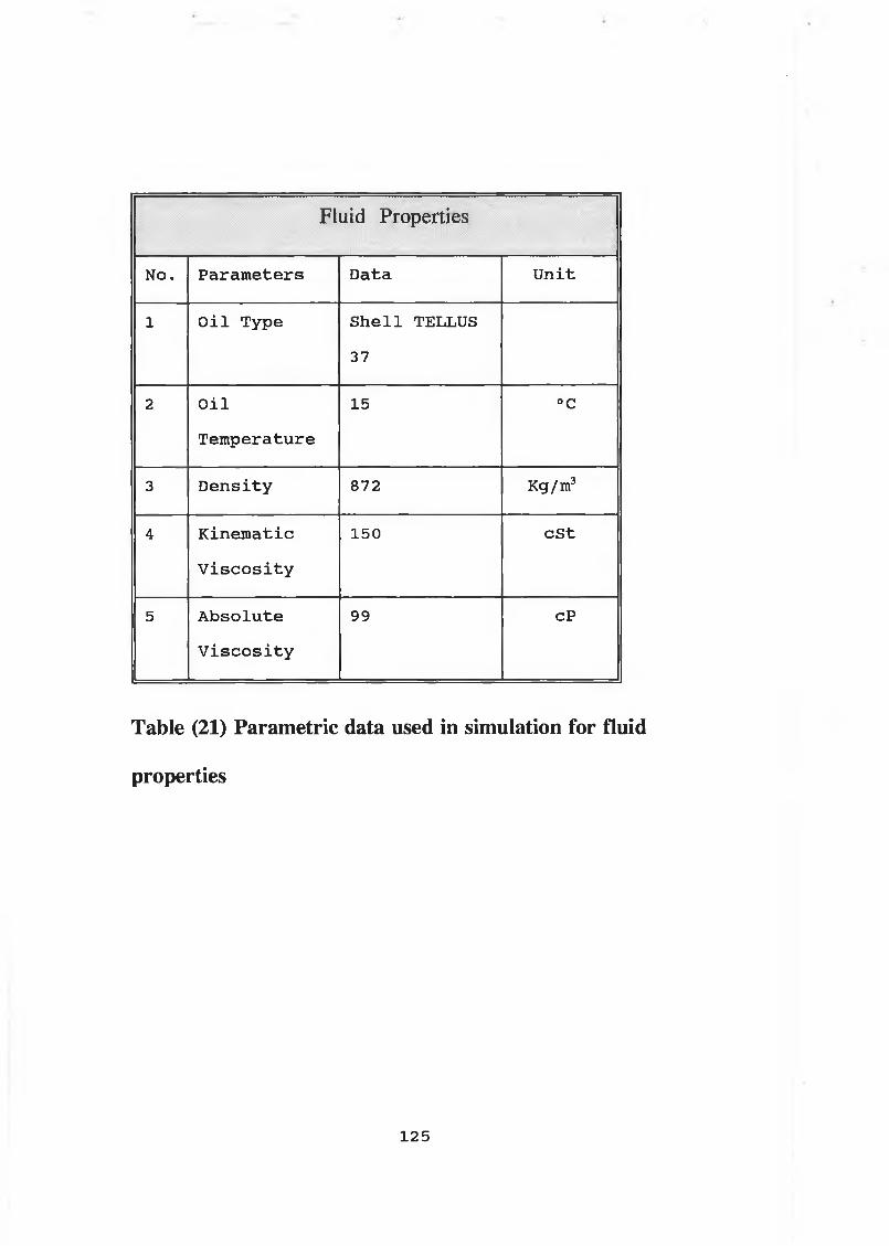
■
Fluid Properties
No. P a ra m eters D ata U n it
1 O i l Type S h e l l TELLUS
37
2 O i l
Tem perature
15 °C
3 D e n s i t y 872 Kg/m3
4 K in e m a t ic
V i s c o s i t y
150 c S t
5 A b s o lu t e
V i s c o s i t y
99 cP
Table (21) Parametric data used in simulation for fluid
properties
125

Component No 1 : Electric MotorJ ' ' ”■ . •
No. In p u t
P a ra m eters
Data U n it
1 Speed 1500 rpm
2 Power 8 .2 Kw
3 Torque 150 Nm
Table (22) Parametric data used in simulation for the
electric motor
126
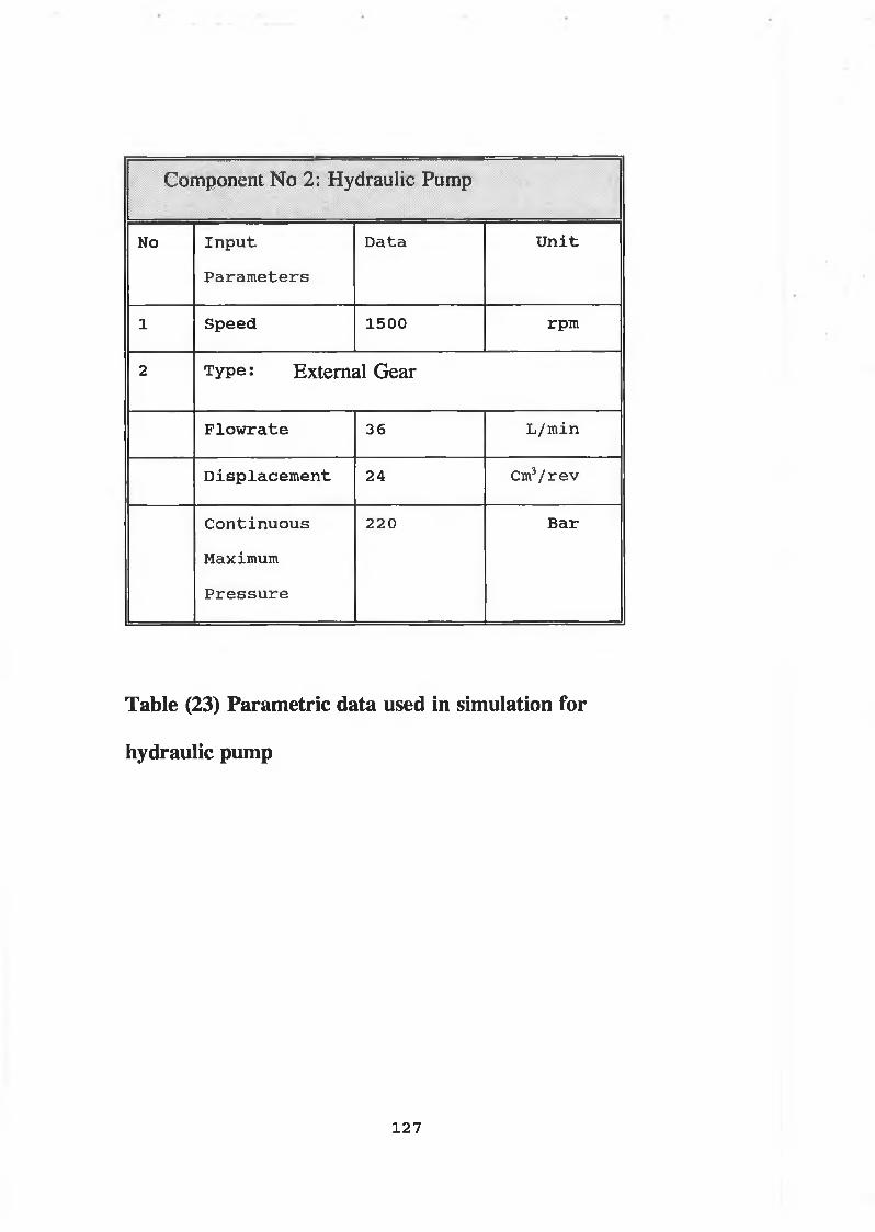
Component No 2: Hydraulic Pump
No In p u t
P a ra m eters
D ata U n it
1 Speed 1500 rpm
2 Type: External Gear
P lo w r a te 36 L/min
D is p la c e m e n t 24 Cm3/ r e v
C o n tin u o u s
Maximum
P r e s s u r e
220 Bar
Table (23) Parametric data used in simulation for
hydraulic pump
127

Component No 3 : Hydrau] ic Motor---------—---i--------------
si'
No I n p u t P a r a m eters D ata U n it
1 type ¡External Gear with External Drain
2 Maximum Speed 2800 rpm
3 F lo w r a te 54 L/m in
4 D is p la c e m e n t 36 Cm3/ r e v
5 C o n tin u o u s
Maximum P r e s s u r e
220 Bar
Table (24) Parametric data used in simulation for
hydraulic motor
128

Component No 4:High Pressure Hose.. '' : ' v:.;- '"v : :
before Directional Control Valve
No. I n p u t
P a r a m eters
D ata U n it
1 P ip e
I n t e r n a l
D ia m eter
1 9 .0 5 mm
2 P ip e L ength 3 .5 m
3 P ip e Volume 0 .9 9 2 L i t r e s
4 A ir
S a t u r a t i o n
P r e s s u r e
0 Bar
Table (25) Parametric data used in simulation for high
pressure pipeline before directional control valve
129

Component No 5 ¡High Pressure Hose'i: :• ?i'1
After Directional Control Valve
No. In p u t
P a r a m eters
Data U n it
l P ip e
I n t e r n a l
D ia m eter
1 2 .7 mm
2 P ip e L ength 0 .3 m
3 P ip e Volume 0 .0 3 8 L i t r e s
4 A ir
S a t u r a t i o n
P r e s s u r e
0 Bar
Table (26) Parametric data used in simulation for high
pressure pipeline after directional control valve
130
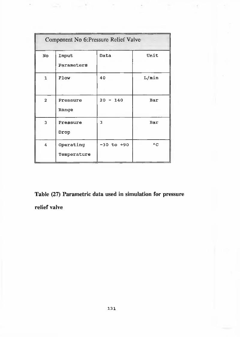
Component No 6:Pressure Relief Valve
No In p u t
P a r a m eters
Data U n it
l Flow 40 L/m in
2 P r e s s u r e
Range
20 - 140 Bar
3 P r e s s u r e
Drop
3 Bar
1 4 O p e r a t in g
T em perature
- 3 0 t o +90 °C
Table (27) Parametric data used in simulation for pressure
relief valve
131
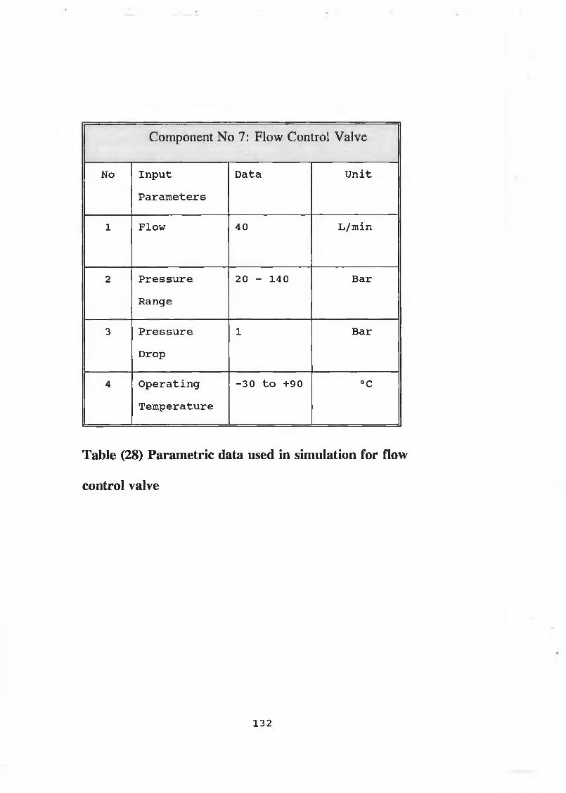
Component No 7: Flow Control Valve
No In p u t
P a r a m eters
Data U n it
1 Flow 40 L/m in
2 P r e s s u r e
Range
20 - 140 Bar
3 P r e s s u r e
Drop
1 Bar
4 O p e r a t in g
Tem perature
-3 0 t o +90 °C
Table (28) Parametric data used in simulation for flow
control valve
132

Component No 8: Check Valve, .....•■ .. -A:: ; 1
No In p u t
P a r a m eters
Data U n it
1 Flow 40 L/m in
2 P r e s s u r e
Range
20 - 140 Bar
3 P r e s s u r e
Drop
2 Bar
4 O p e r a t in g
T em perature
-3 0 t o +
90
°C
Table (29) Parametric data used in simulation for check
valve
133

c<>mponent No 9: 1•••••X- • ’ ’ directional Cor
; ■ Mitrol Valve
No I n p u t
P a r a m eters
Data U n it
1 Flow 40 L/m in
2 P r e s s u r e
Range
20 - 140 Bar
3 P r e s s u r e
Drop
4 Bar
4 O p e r a t in g
Tem perature
- 3 0 t o +90 °C
Table (30) Parametric data used in simulation for
directional control valve
134
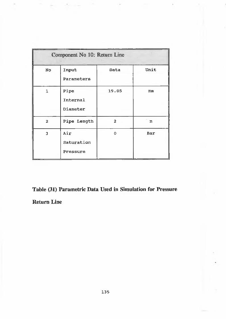
........................- - ........Component No 10: Return Line
: : •: ■ . , . ;;;;; ;■; ; ; ■ : i . _
No I n p u t
P a r a m eters
Data U n it
1 P ip e
I n t e r n a l
D ia m eter
1 9 .0 5 mm
2 P ip e L ength 2 m
3 A ir
S a t u r a t i o n
P r e s s u r e
0 Bar
Table (31) Parametric Data Used in Simulation for Pressure
Return Line
135
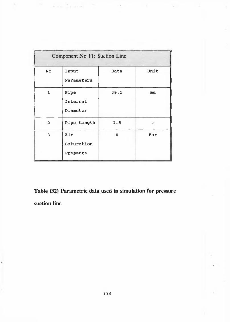
Component No 11: Suction•
Line
No In p u t
P a r a m e te r s
Data U n it
1 P ip e
I n t e r n a l
D ia m eter
3 8 .1 mm
2 P ip e L ength 1 .5 m
3 A ir
S a t u r a t i o n
P r e s s u r e
0 Bar
Table (32) Parametric data used in simulation for pressure
suction line
136
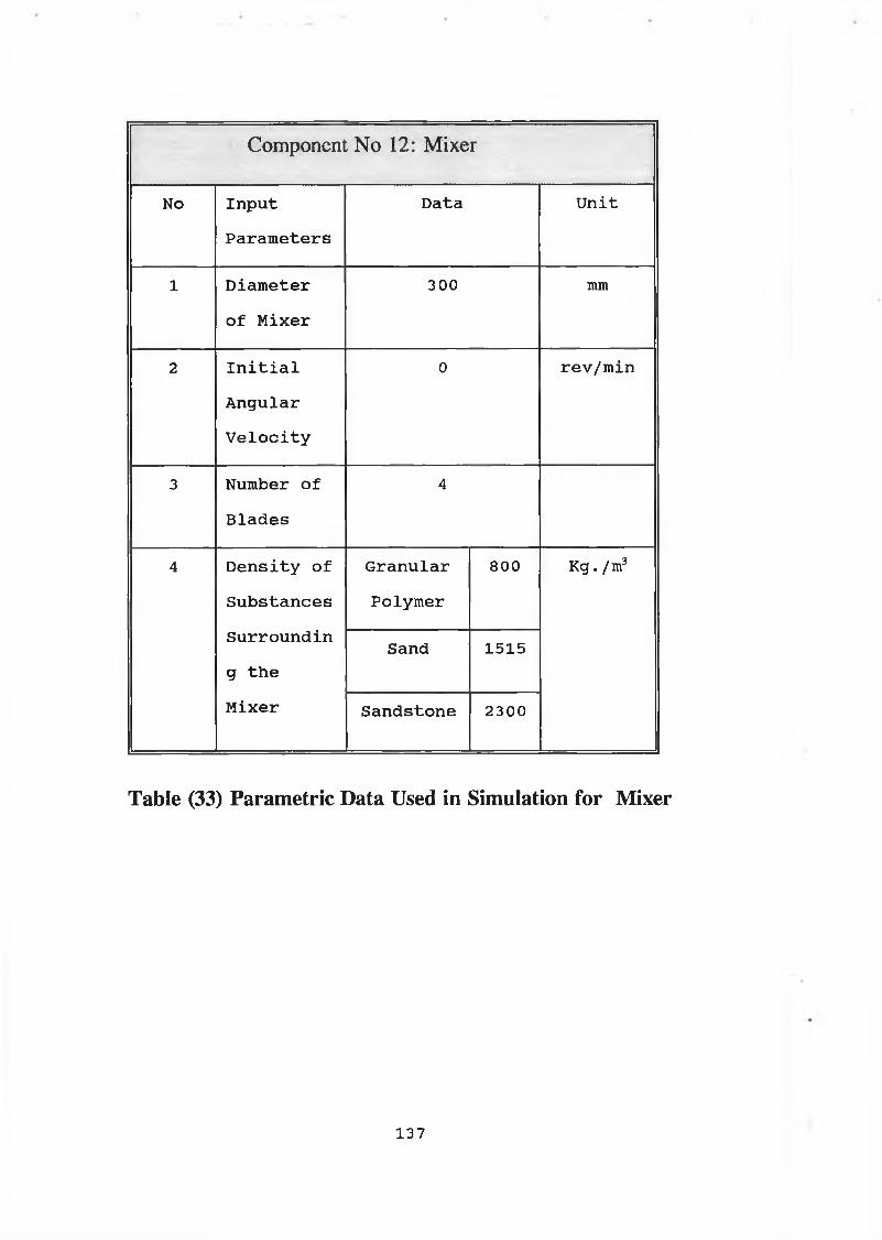
Component No 12: Mixer
No In p u t
P a r a m eters
Data U n it
l D ia m eter
o f M ixer
300 mm
2 I n i t i a l
A n gu lar
V e l o c i t y
0 r e v /m in
3 Number o f
B la d e s
4
4 D e n s i t y o f
S u b s ta n c e s
S u rro u n d in
g t h e
M ixer
G ranular
Polym er
800 Kg. /m3
Sand 1515
S a n d sto n e 2300
Table (33) Parametric Data Used in Simulation for Mixer
137

Component No: 13 Open System
Temperature Model. ;j p|| I
NO. In p u t P a r a m eters Data U n it
1 I n t e r n a l P ip e D ia m eter 1 9 . 05 mm
2 E x t e r n a l P ip e D ia m eter 29 mm
3 L ength o f P ip e 7 m
4 I n i t i a l F lu id Temp. 297 °K
5 I n i t i a l O u ts id e P ip e 295 °K
6 I n i t i a l S u rro u n d in g 293 °K
7 Type o f O i l Used S h e l l
TELLUS 37
8 C o n d u c t iv i t y o f P ip e
W all M a t e r ia l
0 . 013 W/m.K
9 C o n d u c t iv i t y o f F lu id 0 .1 4 4 W/m.K
10 F lu id S p e c i f i c H eat 1964 T /(K g . °K)
11 P ip e W all S p e c i f i c
H eat
2010 J / (K g . °K)
12 E m i s s i v i t y o f P ip e
S e c t i o n
0 .9 4
13 D e n s i t y o f P ip e W all 1100 Kg. /m3
Table (34) Parametric data used in simulation for
temperature and fluid property calculation in the open
hydraulic drive mixer system with hydraulic hoses.
138

Component No: 14 Open System
Temperature Model
No. I n p u t P a ra m eters Data J n i t
1 I n t e r n a l P ip e D ia m eter 19 . 05 mm
2 E x t e r n a l P ip e D ia m eter 25 mm
3 L ength o f P ip e S e c t i o n 7 m
4 I n i t i a l F lu id
Tem perature
297 °K
5 I n i t i a l O u ts id e P ip e 295 °K
6 I n i t i a l S u rrou n d in g
A tm osphere T em perature
293 °K
7 Type o f O i l Used TELLUS37
8 C o n d u c t iv i t y o f P ip e
W all M a t e r ia l
386 W/m.K
9 C o n d u c t iv i t y o f F l u i d 0 .1 4 4 W/m.K
10 F lu id S p e c i f i c H eat 1964 J / (Kg.°K)
11 P ip e W all S p e c i f i c H eat 3831 J / (Kg. °K)
12 E m i s s i v i t y o f P ip e W all 0 . 018
13 D e n s i t y o f P ip e W all 8954 Kg. /m3
Table (35) Parametric data used in simulation for
temperature and fluid property calculation in the open
hydraulic drive mixer system with copper pipes.

Component No: 15 Open System
Temperature ModeliV. ; : !; ;!..... : ■. V: ■: : : : > ..... . .....
No. I n p u t P a r a m eters Data U n it
1 I n t e r n a l P ip e D ia m eter 1 9 .0 5 mm
2 E x t e r n a l P ip e D ia m eter 25 mm
3 L en gth o f P ip e S e c t i o n 7 m
4 I n i t i a l F lu id T em perature 297 °K
5 I n i t i a l O u ts id e P ip e W all
T em perature
295 °K
6 I n i t i a l S u rrou n d in g
A tm osphere T em perature
293 °K
7 Type o f O i l Used SHELL
8 C o n d u c t iv i t y o f P ip e W all
M a t e r ia l
36 W/m.K
9 C o n d u c t iv i t y o f F lu id 0 .1 4 4 W/m.K
10 F l u i d S p e c i f i c H eat 1964 J /(K q .°K )
11 P ip e W all S p e c i f i c H eat 487 J /(K q .°K )
12 E m i s s i v i t y o f P ip e
S e c t i o n
0 .3 2
13 D e n s i t y o f P ip e W all 7833 Kg. /m3
Table (36) Parametric data used in simulation for
temperature and fluid property calculation in the open
hydraulic drive mixer system with steel pipes.
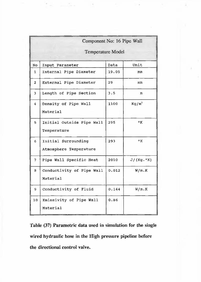
Component No: 16 Pipe Wall
Temperature Model■ .vSpt- it.;:;:™-:5;?11 ' i'lBsl Pv:P . ■ ■ . ' W ' . ' '
No In p u t P aram eter D ata U n it
1 I n t e r n a l P ip e D ia m eter 1 9 . 05 mm
2 E x t e r n a l P ip e D ia m eter 29 mm
3 L ength o f P ip e S e c t i o n 3 . 5 m
4 D e n s i t y o f P ip e W all
M a t e r ia l
1100 Kg/m3
5 I n i t i a l O u ts id e P ip e W all
T em perature
295 °K
6 I n i t i a l S u rrou n d in g
A tm osphere Tem perature
293 °K
7 P ip e W all S p e c i f i c H eat 2010 J / (Kg. °K)
8 C o n d u c t iv i t y o f P ip e W all
M a t e r ia l
0 . 012 W/m.K
9 C o n d u c t iv i t y o f F lu id 0 .1 4 4 W/m.K
10 E m i s s i v i t y o f P ip e W all
M a t e r ia l
0 .8 6
Table (37) Parametric data used in simulation for the single
wired hydraulic hose in the High pressure pipeline before
the directional control valve.
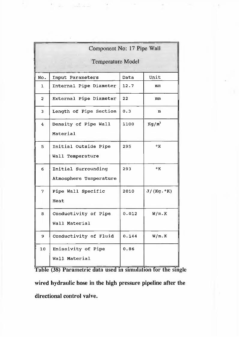
Component No: 17 Pipe Wall
Temperature Model■ : : .... * - ■ ■■:■■■■■' ' . : — ' ■ ■' : ■■. ; ..... : : : ; : .
NO. I n p u t P a r a m eters Data U n it
1 I n t e r n a l P ip e D ia m eter 12 .7 mm
2 E x t e r n a l P ip e D ia m eter 22 mm
3 L ength o f P ip e S e c t i o n 0 .3 m
4 D e n s i t y o f P ip e W all
M a t e r ia l
1100 Kg/m3
5 I n i t i a l O u ts id e P ip e
W all Tem perature
295 °K
6 I n i t i a l S u rrou n d in g
A tm osphere T em perature
293 °K
7 P ip e W all S p e c i f i c
H eat
2010 J /(K g .° K )
8 C o n d u c t iv i t y o f P ip e
W all M a t e r ia l
0 . 012 W/m.K
9 C o n d u c t iv i t y o f F lu id 0 .1 4 4 W/m.K
10 E m i s s i v i t y o f P ip e
W all M a t e r ia l
0 .8 6
Table (38) Parametric data used in simulation for the single
wired hydraulic hose in the high pressure pipeline after the
directional control valve.

Component No: 18 Pipe Wall. • ■ • ■= ■ : ' : : ’
■ • ■ ,, ■; •
Temperature Model
No. In p u t P a r a m eters Data U n it
1 I n t e r n a l P ip e D iam eter 1 9 .0 5 mm
2 E x t e r n a l P ip e D ia m eter 29 mm
3 L en gth o f P ip e S e c t i o n 2 m
4 D e n s i t y o f P ip e W all
M a t e r ia l
1100 Kg/m3
5 I n i t i a l O u ts id e P ip e
W all Tem perature
295 °K
6 I n i t i a l S u rrou n d in g
A tm osphere Tem perature
293 °K
7 P ip e W all S p e c i f i c
H eat
2010 J /(K g .° K )
8 C o n d u c t iv i t y o f P ip e
W all M a t e r ia l
0 .0 1 2 W/m.K
9 C o n d u c t iv i t y o f F lu id 0 . 144 W/m.K
10 E m i s s i v i t y o f P ip e
W all M a t e r ia l
0 .8 6
Table (39) Parametric data used in simulation for the single
wired hydraulic hose at the inlet of the hydraulic motor.
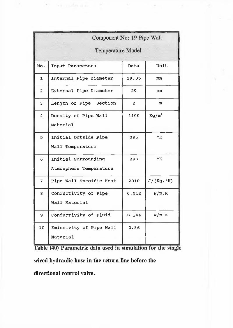
.................Component No: 19 Pipe Wall
.. . • :• ' ' .
Temperature Model
No. I n p u t P a ra m eters Data U n it
1 I n t e r n a l P ip e D ia m eter 1 9 .0 5 mm
2 E x t e r n a l P ip e D ia m eter 29 mm
3 L en gth o f P ip e S e c t i o n 2 m
4 D e n s i t y o f P ip e W all
M a t e r ia l
1100 Kg/m3
5 I n i t i a l O u ts id e P ip e
W all Tem perature
295 °K
6 I n i t i a l S u rro u n d in g
A tm osphere Tem perature
293 °K
7 P ip e W all S p e c i f i c H eat 2010 J / (Kg• °K)
8 C o n d u c t iv i t y o f P ip e
W all M a t e r ia l
0 . 012 W/m.K
9 C o n d u c t iv i t y o f F lu id 0 .1 4 4 W/m.K
10 E m i s s i v i t y o f P ip e W all
M a t e r ia l
0 .8 6
Table (40) Parametric data used in simulation for the single
wired hydraulic hose in the return line before the
directional control valve.
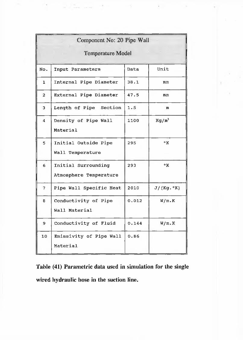
Component No: 20 Pipe Wall
Temperature Model| s „ ■ : ■ ' :: .-t1- - ; :. ■ :
. • ; -- . . ... ... . . .. . : ... • • ;o
No. I n p u t P a r a m eters D ata U n it
1 I n t e r n a l P ip e D iam eter 3 8 .1 mm
2 E x t e r n a l P ip e D iam eter 4 7 .5 mm
3 L ength o f P ip e S e c t i o n 1 .5 m
4 D e n s i t y o f P ip e W all
M a t e r ia l
1100 Kg/m3
5 I n i t i a l O u ts id e P ip e
W all T em perature
295 °K
6 I n i t i a l S u rrou n d in g
A tm osphere T em perature
293 °K
7 P ip e W all S p e c i f i c H eat 2010 J /(K g .° K )
8 C o n d u c t iv i t y o f P ip e
W all M a t e r ia l
0 . 012 W/m.K
9 C o n d u c t iv i t y o f F lu id 0 .1 4 4 W/m.K
10 E m i s s i v i t y o f P ip e W all
M a t e r ia l
0 .8 6
Table (41) Parametric data used in simulation for the single
wired hydraulic hose in the suction line.
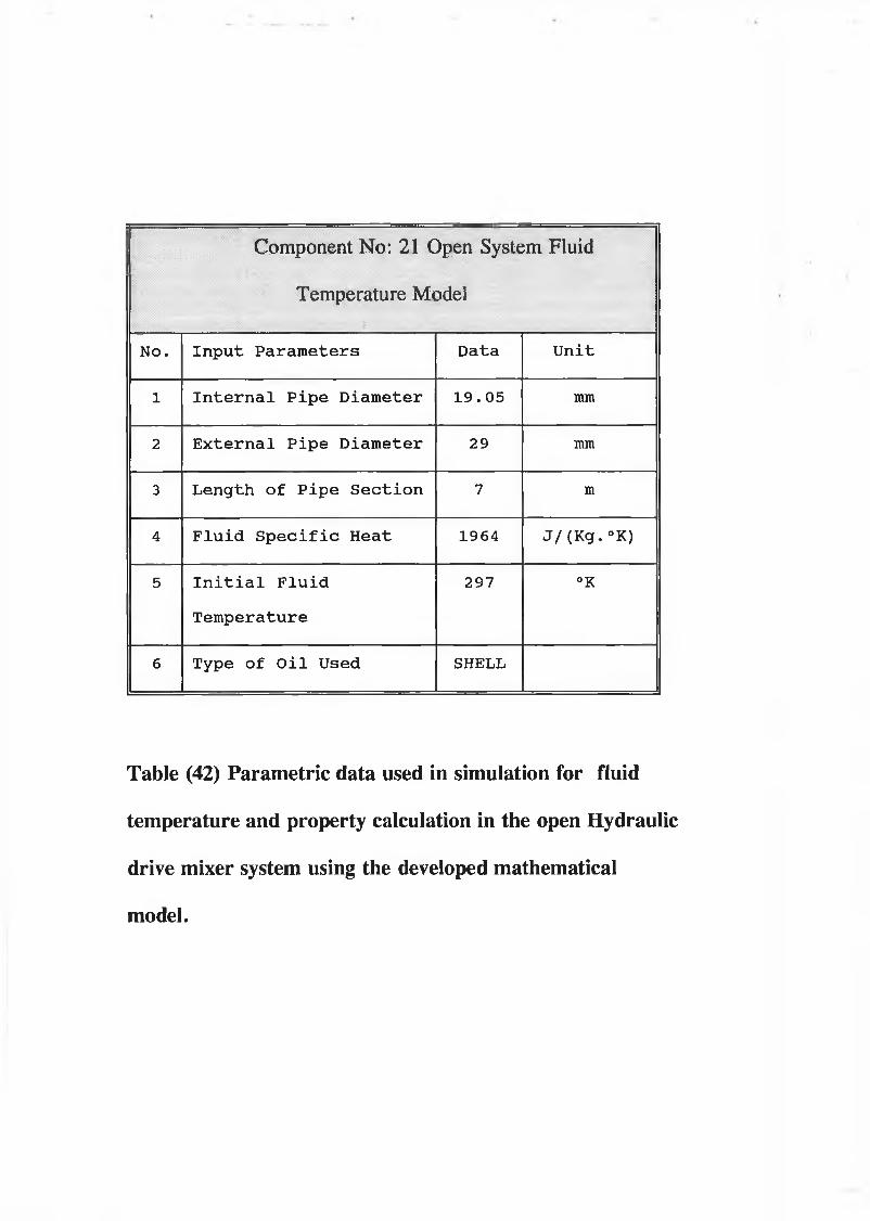
Component No: 21 Open System Fluid
Temperature Model!' ■; §1111H 1: 111 i; 1 1 Mi
No. In p u t P a r a m eters D ata U n it
1 I n t e r n a l P ip e D ia m eter 1 9 .0 5 mm
2 E x te r n a l P ip e D ia m eter 29 mm
3 L ength o f P ip e S e c t i o n 7 m
4 F lu id S p e c i f i c H eat 1964 J / (Kg. °K)
5 I n i t i a l F lu id
T em perature
297 °K
6 Type o f O i l Used SHELL
Table (42) Parametric data used in simulation for fluid
temperature and property calculation in the open Hydraulic
drive mixer system using the developed mathematical
model.
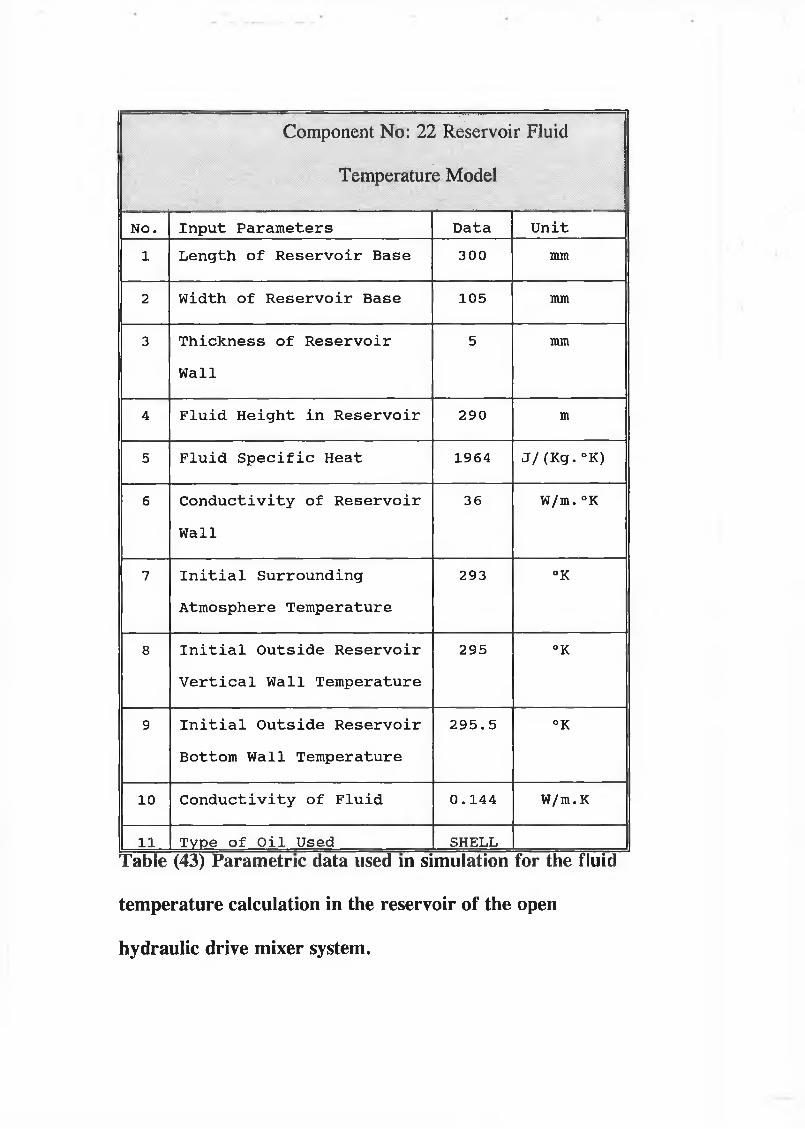
Component No: 22 Reservoir Fluid. ■
Temperature Model. . . . . . . . . . . .
No. In p u t P a r a m eters Data U n it
1 L ength o f R e s e r v o ir B ase 300 mm
2 Width o f R e s e r v o ir B ase 105 mm
3 T h ic k n e s s o f R e s e r v o ir
W all
5 mm
4 F lu id H e ig h t in R e s e r v o ir 290 m
5 F lu id S p e c i f i c H eat 1964 J / (Kg. °K)
6 C o n d u c t iv i t y o f R e s e r v o ir
W all
36 W/m.°K
7 I n i t i a l S u rro u n d in g
A tm osphere Tem perature
293 °K
8 I n i t i a l O u ts id e R e s e r v o ir
V e r t i c a l W all T em perature
295 °K
9 I n i t i a l O u ts id e R e s e r v o ir
Bottom W all Tem perature
2 9 5 .5 °K
10 C o n d u c t iv i t y o f F lu id 0 .1 4 4 W/m. K
11 Type o f O i l Used SHELLTable (43) Parametric data used in simulation for the fluid
temperature calculation in the reservoir of the open
hydraulic drive mixer system.

•Component No: 23 Pipe Fluid
• .... - - j
Temperature Model
No. In p u t P a r a m eters D ata U n it
1 I n t e r n a l P ip e D ia m eter 1 9 .0 5 mm
2 E x t e r n a l P ip e D ia m eter 29 mm
3 L en gth o f P ip e S e c t i o n 1 .5 m
4 F lu id S p e c i f i c H eat 1964 J / ( Kg . ° K)
5 I n i t i a l F lu id
T em perature
297 °K
6 Type o f O i l Used SHELL
Table (44) Parametric data used in simulation for fluid
temperature and property model in the first part of the
high pressure line.

Component No: 24 Pipe Fluid■
. . . . .Temperature Model
•; ; ...... ... . .. . . ' : • .V • . . .'.
No. In p u t P a r a m eters Data U n it
1 I n t e r n a l P ip e D ia m eter 19 . 05 mm
2 E x t e r n a l P ip e D ia m eter 29 mm
3 L ength o f P ip e S e c t i o n 2 m
4 F lu id S p e c i f i c H eat 1964 J / (Kg. °K)
5 I n i t i a l F lu id
Tem perature
297 °K
6 Type o f O i l Used SHELL
Table (45) Parametric data used in simulation for fluid
temperature and property model in the second part of the
high pressure line.

Component No: 25 Pipe Fluid; ■ ■ : : :1 : '■ ...... :
Temperature Model_ ...... : : : , ’ : ”... " '■ ;• ^
NO. I n p u t P a r a m eters Data U n it
1 I n t e r n a l P ip e D ia m eter 1 9 . 0 5 mm
2 E x t e r n a l P ip e D ia m eter 29 mm
3 L ength o f P ip e S e c t i o n 2 m
4 F lu id S p e c i f i c H eat 1964 J / (Kg. °K)
5 I n i t i a l F lu id
T em perature
297 °K
6 Type o f O i l Used SHELL
Table (46) Parametric data used in simulation for fluid
temperature and property model in the return line

Component No: 26 Pipe Fluid■ . ' . ■ " _ • • • • ' ■ ■ '....'••••• ••••• ̂ •••- . -:... . • y . •
v" ■ ■ .Temperature Model
• ■ - ' • i ■ ■ • . ■ ■ ■ ■ . ■ ■
No. In p u t P a r a m eters Data U n it
1 I n t e r n a l P ip e D ia m eter 3 8 . 1 mm
2 E x t e r n a l P ip e D ia m eter 4 7 . 5 mm
3 L ength o f P ip e S e c t i o n 1 .5 m
4 F lu id S p e c i f i c H eat 1964 J / (Kg. °K)
5 I n i t i a l F lu id
T em perature
297 °K
6 Type o f O i l Used SHELL
Table (47) Parametric data used in simulation for fluid
temperature and property model in the suction line

Surroundings Boundary
Fig (21) Open thermal system undergoing an imaginary non-flow process

154
Fig (22) The flow of a closed system (the shaded area) through the space occupied by an open system, conversion of the first-law statement for closed systems into a statement valid for open systems.
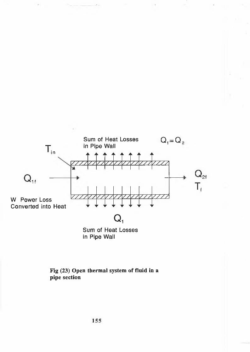
T n
Sum of Heat Losses in Pipe Wall Q1 = Q
7 7 7 7
Qit
W Power Loss Converted into Heat
ZZ Z2 ZZ 7 7 Z Z ZZ ZZz ZZZZl
ZZZZZZ ZZzzzz ZZ ZZZZl
QiSum of Heat Losses in Pipe Wall
Q 2f
T,
Fig (23) Open thermal system of fluid in a pipe section
1 5 5

Q, (Heat Flow Transferred from Oil to Hose W all)
Qz (Heat Flow Transferred from Hose Wall to Surrounding)
Fig (24) Heat flow losses through the hose in surroundings

Fig. (25) Heat flow through a hydraulic hose
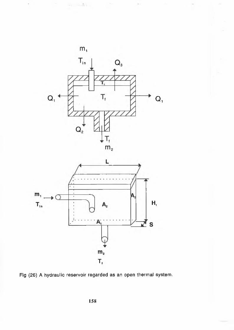
m 1
Q i
H,
Tt
Fig (26) A hydrau lic reservo ir regarded as an open thermal system .
158
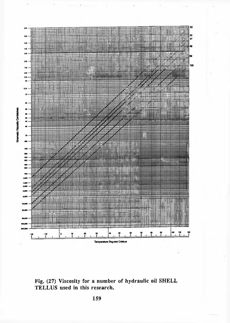
TampMU* DegrtM C«Wua
Fig. (27) Viscosity for a number of hydraulic oil SHELL TELLUS used in this research.
159
8 ft

3 4 5 6 70I I I I I
3 4 5 6 / 8T I l~ I T
Curves lor relative roughness
^ Irom 0.000001 to 0.050
wharf t * sim of surface imper lections in feel or meters
D ■ actual inside diameter m feet or rr.tMi-rs
0.030
0.025
- 0.020
0.015
6 7 8 1 5 210s
3 4 0 6 7 8 1.5 210*
Reynolds number=
Fig. (28) Friction factor vs. Reynolds number for turbulent flow.

V ilv e i- f it t in g tLD KvMlue
swing check valve 135 2.50globe valve 340 10.00gate valve
(lull open) 13 0. IB1/4 closed 35 1.151/2 closed 160 5.603/4 closed 900 24.00
cock valve 18 .26close pattern return bend 50 2.20standard tee 60 1.80standard 90* elbow 30 0.90standard 45* elbow 16 0.42
Swing check valve.
Flow in this direction only
Gate valve Cock valve
Close pattern return bend
Standard elbows
90‘ 45‘
Inwardprojecting
Globe valve
Pipe entrance
'M K
0 00 ' OS0 02 0 78004 0.2«0 0 6 0.150.10 0.09
0 15 and up 0.04
Flush
r
K * 0.78 *Sharpedged
Pipe exit
Projecting Sharp-edged
K « 1.0
I
K - 1.0
fciFor K,
see tablr
Rounded
K - 1.0
F ig . (2 9 ) K -va lu es for severa l va lves and fittin gs.
161
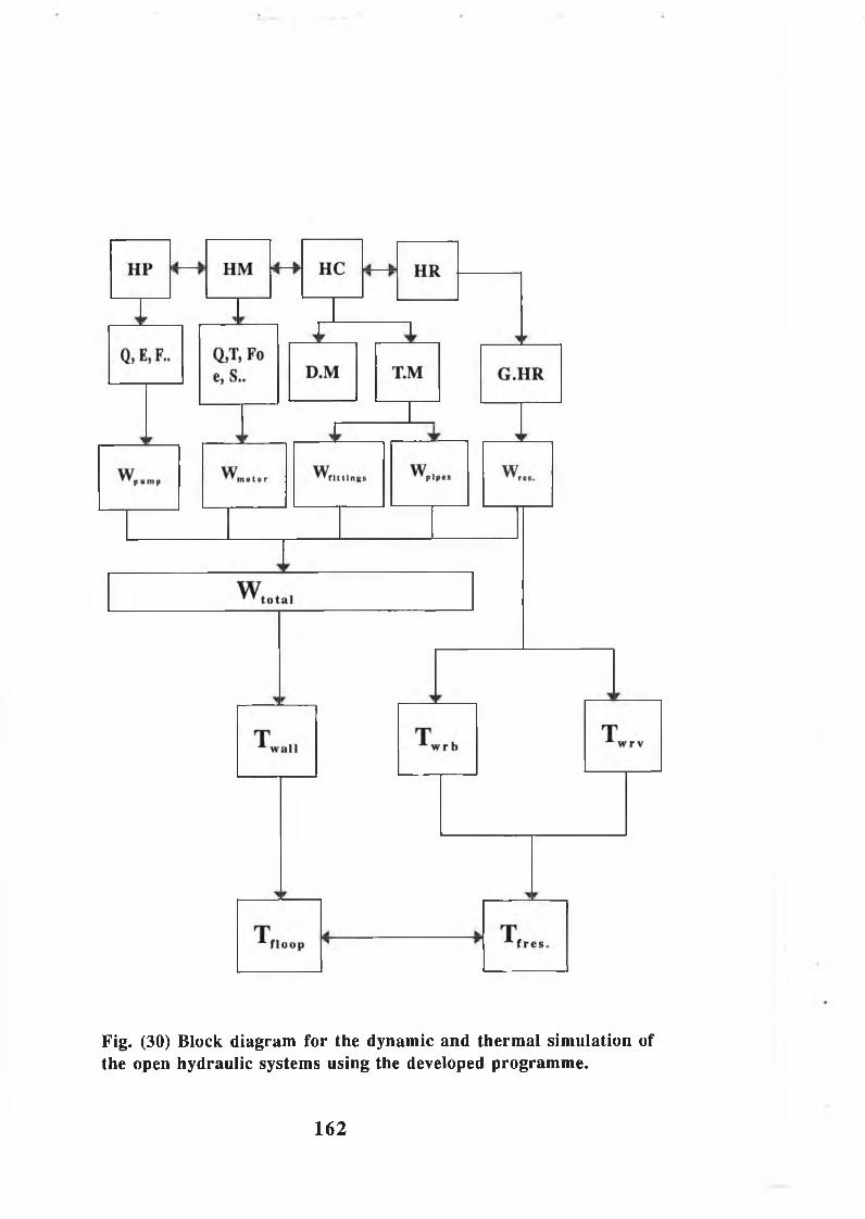
Fig. (30) Block diagram for the dynamic and thermal simulation of the open hydraulic systems using the developed programme.
162

Temp
eratur
e [ °
C]
System Loading Time in Second x 60
Fig. (31) The effects of power loss on the fluid temperature in the openhydraulic drive mixer system
163
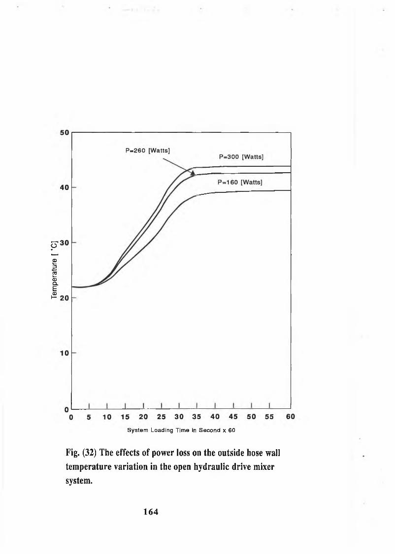
Temp
eratur
e [ ‘
C]
System Loading Time in Second x 60
Fig. (32) The effects of power loss on the outside hose wall
tem perature variation in the open hydraulic drive mixer
system.
164

Temp
eratur
e [
°C]
System Loading Time In Second x GO
Fig. (33) The effects of pipelength on the fluid temperature variation in the openhydraulic drive mixer system.
165

Temp
eratur
e [ °
C]
50
1
L( 1)=5 [m]L(2) = 7.5 [m]
r /-V U
)'w
' If VO m)
L(4)= 11.5 [m]
0 5 10 15 20 25 30 35 40 45 50 55 60System Loading Time in Second x 60
Fig. (34) The effects of pipelength on the outside hose wall temperaturevariation in the open hydraulic drive mixer system.
166
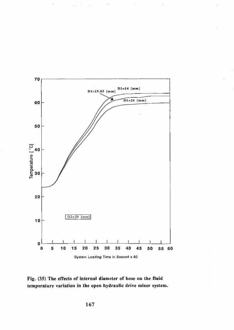
Temp
eratur
e [ °
C]
System Loading Time in Second x 60
Fig. (35) The effects of internal diameter of hose on the fluidtemperature variation in the open hydraulic drive mixer system.

50
1
[)(1 )=26 [ i i i i i i ]
D (2)=23 [mm] D (3)=19.05 [mm] I)(4 )= 14.0 [mm]
D2=29 [mm]
0 5 10 15 20 25 30 35 40 45 50 55 60
System Loading Time in Second x 60
Fig. (36) The effects of internal diameter of hose on the outside hose walltemperature variation in the open hydraulic drive mixer system.
168

Temp
eratur
e [ °
C]
System Loading Time In Second x 60
Fig. (37) The effects of external hose diameter on the outside hosewall temperature variation in the open hydraulic drive mixer system.
169
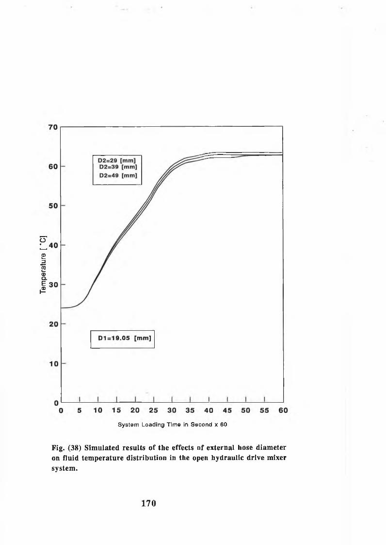
Temp
eratur
e [ ’
C]
System Loading Time in Second x 60
Fig. (38) Simulated results of the effects of external hose diameteron fluid temperature distribution in the open hydraulic drive mixersystem.
170

Temp
eratur
e [ ’
C]
System Loading Time in Second x 60
Fig. (39) The effects of conductivity of pipe wall material on fluidtemperature variation in the open hydraulic drive mixer system.
171

System Loading Time in Second x 60
Fig. (40) The effects of conductivity of pipe material on the outsidehose wall temperature variation in the open hydraulic drive mixersystem.
17 2
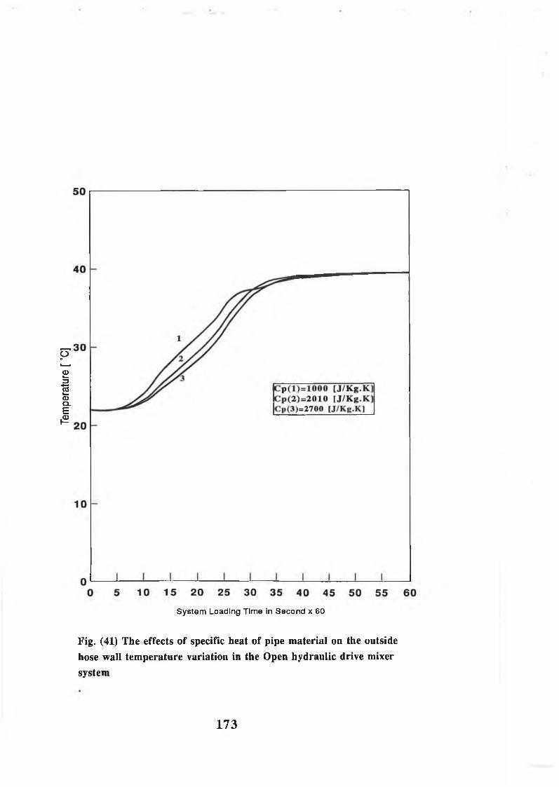
Temp
eratur
e [ ’C
]
System Loading Time In Second x 60
Fig. (41) The effects of specific heat of pipe material on the outsidehose wall temperature variation in the Open hydraulic drive mixersystem
173

Temp
eratur
e [ °
C]
System Loading Time in Second x 60
Fig. (42) The effects of specific heat of pipe material on fluidtemperature variation in the open hydraulic drive mixer system.
174

Temp
eratur
e [ °
C]
System Loading Time In Second x 60
Fig. (43) Tlie effects of density o f pipe material on the outside hose wall temperature variation in the open hydraulic drive mixer system
175

Temp
eratur
e [ “
C]
System Loading Time in Second x 60
Fig. (44) Simulated results of the effects of density of pipe material on fluid temperature variation in the open hydraulic drive mixer system.
176

Temp
eratur
e [ ’
C]
System Loading Time in Second x 60
Fig. (45) The effects of emissivity of pipe material on the outside hosewall temperature variation in the open hydraulic drive mixer system.
177

Temp
eratur
e [ "
C]
Fig. (46) The effects of emissivity of pipe material on fluid temperaturevariation in the open hydraulic drive mixer system.

Temp
eratur
e [ °
C]
System Loading Time in Second x 60
Fig. (47) Simulated results of the effects of type of pipe material on outside pipe wall temperature in the open hydraulic drive mixer system.
179

Temp
eratur
e [ °
C]
System Loading Time in Second x 60
Fig. (48) Simulated results of the effects of type of pipe materialon fluid temperature in the open hydaulic drive mixer system.
180

Temp
eratur
e [ 'C
]
System Loading Time x 60
Fig. (49) Comparison of the effects of radiation on the fluidtemperature in the open hydraulic drive mixer system.
181
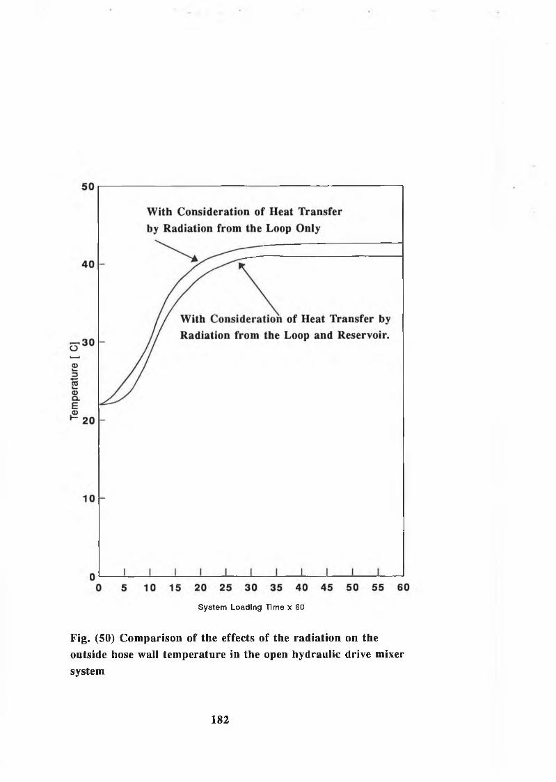
System Loading Time x 60
Fig. (50) Comparison of the effects of the radiation on theoutside hose wall temperature in the open hydraulic drive mixersystem
182
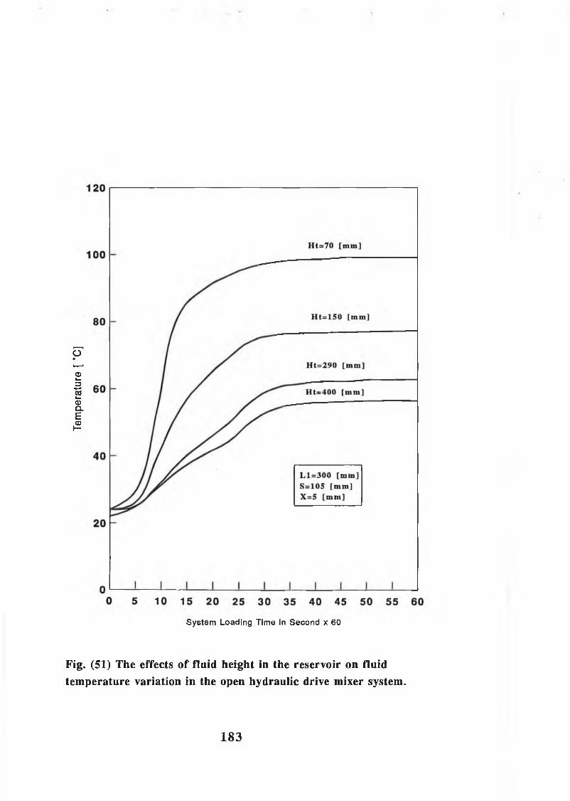
Temp
eratur
e [ °
C]
System Loading Time in Second x 60
Fig. (51) The effects of fluid height in the reservoir on fluidtemperature variation in the open hydraulic drive mixer system.
1 8 3

System Loading Time in Second x 60
Fig. (52) The effects of fluid height in the reservoir on theoutside hose wall temperature variation in the open hydraulicdrive mixer system.
184

System Loading Time in Second x 60
Fig. (53) The effects of length of the Base of the reservoir on fluidtemperature variation in the open hydraulic drive mixer system.
185

System Loading Time in Second x 60
Fig. (54) The effects of the length of the base of thereservoir on the outside hose wall temperature variationin the open hydraulic drive mixer system.
186

Tem
pera
ture
[
°C]
System Loading Time in Second x 60
Fig. (55) The effects of the width of the base of the reservoir onfluid temperature variation in the open hydraulic drive mixersystem.
187

Temp
eratur
e [ °
C]
System Loading Time in Second x 60
Fig. (56) The effects of the width of the base of reservoir on theoutside hose wall temperature in the open hydraulic drive mixersystem.
188

Tem
pera
ture
[
'C]
System Loading Time in Second x 60
Fig. (57) The effects of thickness of the wall of the reservoir on the fluid temperature variation in the open hydraulic drive mixer system
189
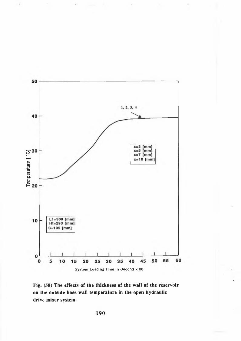
Temp
eratur
e [ °
C]
System Loading Tim e in Second x 60
Fig. (58) The effects of the thickness of the wall of the reservoiron the outside hose wall temperature in the open hydraulicdrive mixer system.
190

Temp
eratur
e [ “
C]
System Loading Time in Second x 60
Fig. (59) The effects of Material of the reservoir on fluidtemperature variation in the open hydraulic drive mixer system.
191

Temp
eratur
e [ *
C]
System Loading Time in Second x 60
Fig. (60) The effects of material of the reservoir on the outside hosewall temperature variation in the open hydraulic drive mixer system.
19 2

Temp
eratur
e [ °
C]
8 0
,1 I I___I___I___I___I___1 I I I I0 5 10 15 20 25 30 35 40 45 50 55 60
System Loading Time in Second x 60
Fig. (61) Simulated results of the effects of exchange flow rate between loop and reservoir on loop fluid temperature in the open hydraulic drive mixer system.
193
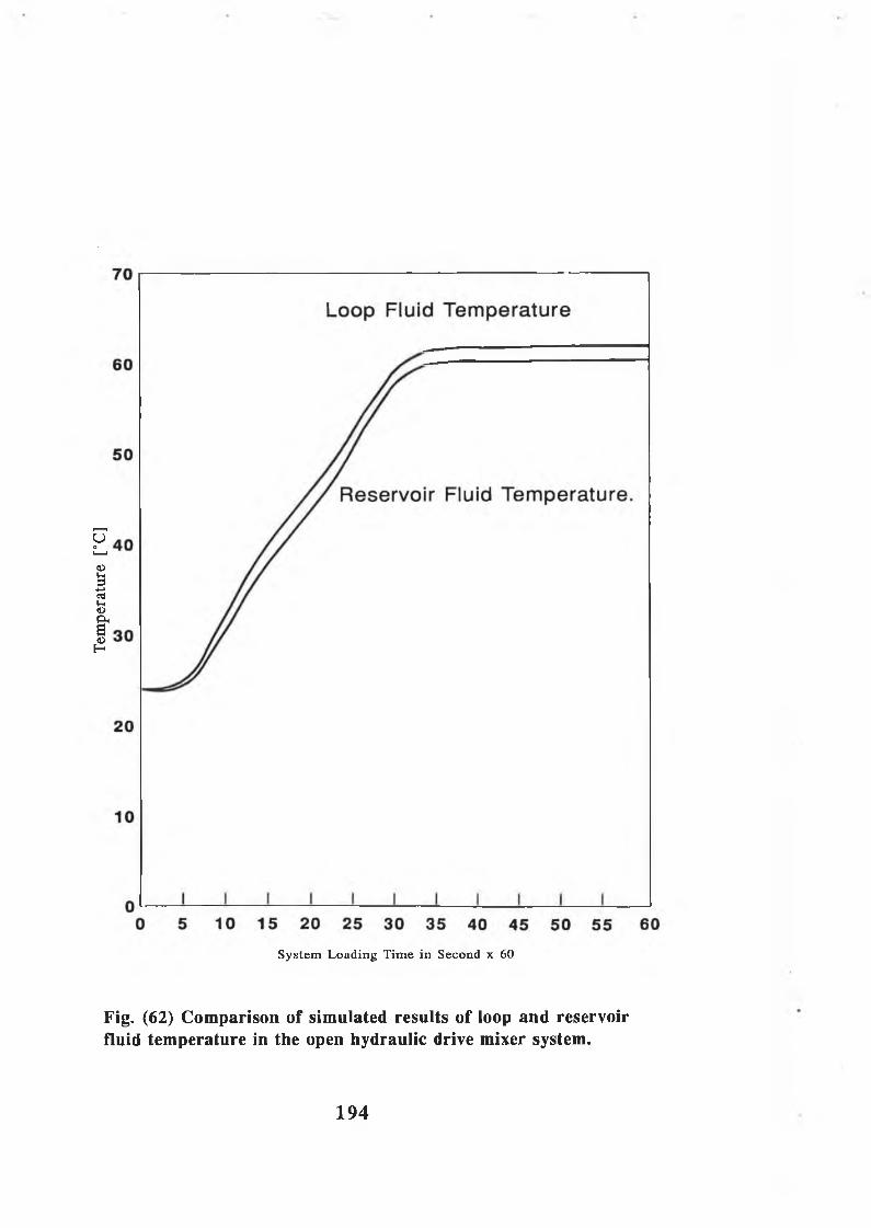
Tem
pera
ture
[°C
]
S ystem L oading T im e in Second x 60
Fig. (62) Comparison of simulated results of loop and reservoir fluid temperature in the open hydraulic drive mixer system.
194

System L oading T im e in Second x 60
Fig. (63) Comparison of simulated results of loop and reservoir fluid temperature with consideration of heat Transfer by radiation in the open hydraulic drive mixer system.
195
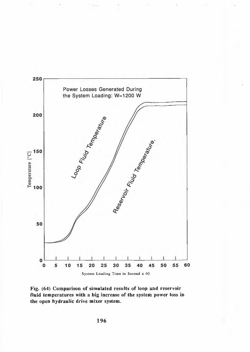
S ystem L oading T im e in Second x 60
Fig. (64) Comparison of simulated results of loop and reservoir fluid temperatures with a big increase of the system power loss in the open hydraulic drive mixer system.
196

CHAPTER: 4
Experimental Investigation and Results
4.1. Experimental Procedure:The f o l l o w i n g p r o c e d u r e was
f o l l o w e d b e f o r e c a r r y in g o u t any t e s t . The h y d r a u l i c o i l
r e s e r v o i r was f i l l e d w i t h S h e l l TELLUS-37 o i l t o t h e
l e v e l mark on t h e s i g h t g l a s s . The s e t t i n g o f t h e r e l i e f
v a l v e was a d j u s t e d on 150 b ar a s a s y s te m w ork in g
p r e s s u r e . The c o n t a in e r was f i l l e d w i th d i f f e r e n t
m a t e r i a l t o g e t d i f f e r e n t lo a d . The s y s te m c o n t r o l v a l v e
was in t h e OFF p o s i t i o n . Four th e r m o c o u p le s w i th d i g i t a l
o u tp u t w ere a t t a c h e d f i r m l y on t h e s u r f a c e o f s u c t i o n
l i n e , p r e s s u r e l i n e and r e t u r n l i n e . Three q u ic k -
d i s c o n n e c t a b l e h o s e c o u p l i n g s w ere c o u p le d w i th t h e
h o s e s w here f r e q u e n t c o n n e c t io n a r e made and broken
b etw een t h e h o s e s .
A f t e r t h e ab ove a rra n g em en t, t h e h y d r a u l i c pump was run
a t 1500 r .p .m and t h e s o l e n o i d d i r e c t i o n a l c o n t r o l v a l v e
was s w i t c h e d on . The h y d r a u l i c s y s te m was run i n o f f
l o a d c o n d i t i o n f o r 5 m in u te s t o a l l o w a i r t o be f u l l y
e x p e l l e d from t h e s y s te m . In o r d e r t o run t h e d r iv e
m otor ( h y d r a u l i c m otor) , t h e h a n d le o f t h e c o n t r o l v a l v e
was moved t o ON p o s i t i o n . The e n t i r e s y s te m i n s t a l l a t i o n
was c h e c k e d f o r o i l l e a k s and r e c t i f i e d when n e c e s s a r y .
197

The s y s te m was run f o r on e hour u n d er lo a d i n o r d e r t o
r e a c h t h e s t e a d y th e r m a l c o n d i t i o n . I n i t i a l l y , t h e p ip e
w a l l and f l u i d t e m p e r a tu r e s ch an ged r a p i d l y and t h e
t e m p e r a tu r e r e a d in g s w ere t h e r e f o r e r e c o r d e d a t one
m in u te i n t e r v a l f o r t h e f i r s t f i v e m in u t e s , e v e r y two
m in u te s f o r t h e f o l l o w i n g 25 m in u te s and t h e n e v e r y f i v e
m in u te s to w a rd s t h e end o f t h e t e s t s .
F o l lo w in g c l o s e l y t h e a b ove t e s t p r o c e d u r e , an e x t e n s i v e
t e s t programme was u n d e r ta k e n t o i n v e s t i g a t e
e x p e r i m e n t a l l y t h e f e a s i b i l i t y o f p r o v id in g an e f f i c i e n t
o i l c o o l e r t o s m a l l s i z e d h y d r a u l i c c i r c u i t s w h ich w i l l
r e d u c e h e a t p r o b le m s , r e s e r v o i r s i z e and w i l l be an
i n t e g r a l p a r t o f t h e c i r c u i t . In a d d i t i o n , t h e
e x p e r im e n t a l r e s u l t s w ere r e c o r d e d t o v e r i f y t h e
d e v e lo p e d m a th e m a t ic a l m o d e l .
4.2. Experimental Results: A t y p i c a l s e t o f te m p e r a tu r e
r e c o r d i n g s from t h e e x p e r im e n ta l t e s t i s p r e s e n t e d in
F i g . (65) t o F ig ( 9 4 ) . T h ese te m p e r a tu r e v a l u e s were
o b t a in e d from t h e e x p e r im e n ta l r e c o r d i n g s a t e a c h t im e
i n t e r v a l , b u t f o r t h e c o n v e n ie n c e o f t e m p e r a tu r e
a n a l y s i s , a l l d a ta o f t h e e x p e r im e n ta l r e s u l t s h ave been
s im p ly j o i n e d t o g e t h e r w i t h c u r v e s . Some m inor s c a t t e r
was o b s e r v e d a s shown in some e x p e r im e n ta l t e m p e r a tu r e
r e s u l t s . N e v e r t h e l e s s , t h e s e e x p e r im e n ta l c u r v e s can
i n d i c a t e t h e t r e n d s o f te m p e r a tu r e r i s e w i t h s u f f i c i e n t
a c c u r a c y .
198

F i g . (65) shows t h e m easured te m p e r a tu r e o f t h e o u t s i d e
h o s e w a l l a t t h e e n t r y and e x i t p o i n t s o f t h e h y d r a u l i c
m otor f o r a f lo w r a t e o f 3 0 1 /m in I t was o b se r v e d in
t h i s f i g u r e t h a t t h e m easured te m p e r a tu r e s i n c r e a s e d
r a p i d l y w i t h in t h e f i r s t 3 0 m in u te s o f t h e sy ste m
l o a d i n g t im e w h i l e i n t h e s e c o n d 3 0 m in u te s o f t h e
o p e r a t i o n , t h e ch an ge i n t h e te m p e r a tu r e was lo w e r th a n
t h e f i r s t 3 0 m in u t e s . T h is i s due t o t h e a c h ie v e m e n t o f
t h e s t e a d y s t a t e o f t h e f l u i d t e m p e r a tu r e .
F i g s (66) t o (69) show t h e m easured te m p e r a tu r e o f th e
o u t s i d e h o s e w a l l o f s e c o n d p a r t o f p r e s s u r e l i n e and
r e t u r n l i n e o f t h e h y d r a u l i c m otor f o r f lo w r a t e s o f 25 ,
2 0 , 1 0 , and 5 1 /m in r e s p e c t i v e l y . The g e n e r a l t r e n d s o f
t h e r e s u l t s w ere fou nd t o be s i m i l a r t o t h o s e in f i g .
( 6 5 ) . H ig h er t e m p e r a tu r e s w ere r e c o r d e d a t h ig h e r lo a d s
and lo w e r f l o w r a t e a s shown in f i g s (68) and ( 6 9 ) .
F i g . (70) shows t h e m easured te m p e r a tu r e o f t h e o u t s i d e
h o s e w a l l o f t h e f i r s t p a r t o f t h e p r e s s u r e l i n e and
s u c t i o n l i n e o f h y d r a u l i c pump f o r f lo w r a t e o f 30 1 /m in
T h is f i g u r e show s h ig h e r r a t e o f te m p e r a tu r e a s
r e c o r d e d d u r in g t h e f i r s t 3 5 m in u te s o f t h e sy s te m
l o a d i n g t im e . For s y s te m lo a d in g t im e i n e x c e s s o f ab ou t
50 m in u t e s , t h e r e c o r d e d t e m p e r a tu r e s w ere o b se r v e d t o
be a p p r o x im a te ly c o n s t a n t due t o t h e s t a b i l i t y o f s t e a d y
s t a t e c o n d i t i o n .
199

F i g s (71) t o (74) g i v e t h e m easured t e m p e r a tu r e s o f t h e
o u t s i d e h o s e w a l l o f t h e f i r s t p a r t o f t h e p r e s s u r e l i n e
and s u c t i o n l i n e o f t h e h y d r a u l i c pump f o r f lo w r a t e s o f
2 5 , 2 0 , 10 , and 5 1 /m in r e s p e c t i v e l y . The r e s u l t s o f
t h e s e f i g u r e s w ere found t o be s i m i l a r t o t h o s e i n f i g .
(7 0) . The m easured te m p e r a tu r e s w ere g r e a t e r a s t h e lo a d
was i n c r e a s e d . For t h e s y s te m lo a d in g t im e i n e x c e s s o f
a b o u t 55 m in u t e s , t h e te m p e r a tu r e r e a d in g s w ere found t o
be a p p r o x im a te ly c o n s t a n t .
F i g . (75) shows t h e e x p e r im e n ta l r e s u l t s o f te m p e r a tu r e
v a r i a t i o n o f f l u i d f o r f lo w r a t e o f 3 0 1 /m in in t h e open
h y d r a u l i c d r i v e m ix e r s y s t e m . In t h i s f i g u r e , th e
t e m p e r a tu r e i n c r e a s e s a s t h e s y s te m lo a d i n g t im e
i n c r e a s e s f o r up t o 3 0 m in u te s ; a f t e r 30 m in u te s o f t h e
o p e r a t i o n under t h e l o a d , t h e te m p e r a tu r e i s changed
s l i g h t l y due t o t h e th e r m a l s t e a d y s t a t e . F i g s . (76) t o
(78) w ere fou nd t o be s i m i l a r t o t h o s e i n F i g . ( 7 5 ) .
F ig s (79) and (80) show t h e r e s u l t s o f t h e e f f e c t s o f
f lo w r a t e on t h e o u t s i d e h o s e w a l l t e m p e r a tu r e o f t h e
r e t u r n and p r e s s u r e l i n e s r e s p e c t i v e l y . T h ese f i g u r e s
show t h a t t h e m easured te m p e r a tu r e o f t h e o u t s i d e h o se
w a l l i s i n c r e a s e d a s f lo w r a t e i s d e c r e a s e d t h e r e f o r e
p r e s s u r e i s i n c r e a s e d . I t was o b se r v e d t h a t t h e change
o f t h e m easured te m p e r a tu r e a t f lo w r a t e o f 1 0 , 5 1 /m in
(P=110, 140 bar) i s much h ig h e r compared t o t h o s e shown
i n t h e same f i g u r e s f o r f lo w r a t e o f 30 , 25 and 20 1 /m in
200
F i g s . (81) and (82) d e m o n s tr a te t h e e x p e r im e n ta l r e s u l t s
o f t h e e f f e c t s o f t h e f lo w r a t e on f l u i d t e m p e r a tu r e o f
r e t u r n l i n e and p r e s s u r e l i n e in t h e open h y d r a u l i c
d r i v e m ix e r s y s t e m . The g e n e r a l t r e n d s o f t h e r e s u l t s
w ere fou n d t o be s i m i l a r t o t h e s e in F i g s . 79 and 80 .
H ig h er v a l u e s o f t e m p e r a tu r e w ere o b s e r v e d f o r low er
v a l u e s o f f l o w r a t e .
The c o n s t a n t t e m p e r a tu r e v a l u e s o f s t e a d y s t a t e h a v e n o t
b een a c h ie v e d i n some e x p e r im e n ta l r e s u l t a s shown in
F ig . (83) w hich shows t h e co m p a r iso n o f h o s e w a l l
te m p e r a tu r e b etw een p r e s s u r e and r e t u r n l i n e s in t h e
open h y d r a u l i c d r i v e s y s t e m . A p o s s i b l e r e a s o n i s t h e
g r a d u a l i n c r e a s e in t h e a tm o s p h e r ic te m p e r a tu r e
s u r r o u n d in g t o t h e t e s t r i g d u r in g t h e t e s t s o f sy stem
l o a d i n g . M oreover, f l u i d te m p e r a tu r e a t t h e m otor i n l e t
i n t h e se c o n d p a r t o f t h e h ig h p r e s s u r e l i n e i s
a p p r o x im a te ly 3 °C h ig h e r th a n o f t h a t r e c o r d e d a t t h e
pump o u t l e t in t h e f i r s t p a r t o f t h e h ig h p r e s s u r e l i n e
a s shown in F i g . (84) . However, on t h e b a s i s o f t h e w e l l
known t e m p e r a t u r e - p r e s s u r e drop c o e f f i c i e n t 5 °C /100 bar
, R e f . (48) , i n a p ip e l i n e , i t can be s e e n t h a t t h e 3 °C
d i f f e r e n c e v a l u e i n t h e e x p e r i m e n t a l l y m easured f l u i d
t e m p e r a t u r e s i n t h e p a r t s o f t h e h ig h p r e s s u r e l i n e i s
o n ly p a r t l y c a u se d by t h e p r e s s u r e l o s s e s a c r o s s t h e
f i t t i n g s , b u t m a in ly c a u se d by t h e e r r o r s in
m easu rem en ts o f t h e e x p e r im e n ta l f l u i d t e m p e r a tu r e .
201
S i m i l a r l y , a s m a l l t e m p e r a tu r e d i f f e r e n c e i s shown in
t h e c o r r e s p o n d in g p ip e w a l l t e m p e r a tu r e s a s shown in
F i g . ( 8 5 ) . T h ese s m a l l t e m p e r a tu r e d i f f e r e n c e s can be
i g n o r e d , s o t h a t t h e f l u i d te m p e r a tu r e a s w e l l a s p ip e
w a l l t e m p e r a tu r e can be r e g a r d e d a s h a v in g u n ifo r m v a lu e
o v e r t h e p i p e l i n e . However, t h e e x p e r i m e n t a l l y o b t a in e d
te m p e r a tu r e r e s u l t s from t h e d i f f e r e n t p a r t s o f t h e
s y s te m show a s i g n i f i c a n t d i f f e r e n c e b e tw een t h e f l u i d
and p ip e w a l l t e m p e r a tu r e , t y p i c a l ex a m p le s a r e shown in
F i g s . (86) and ( 8 7 ) . T h ese te m p e r a tu r e d i f f e r e n c e s
b etw een t h e f l u i d and p ip e w a l l can n o t be ig n o r e d even
i f t h e e x p e r im e n ta l m easurem ent e r r o r s h a v e b een ta k e n
i n t o a c c o u n t .
F i g . (88) d e m o n s tr a te s t h e h o s e w a l l t e m p e r a tu r e in
d i f f e r e n t p a r t s o f t h e s y s t e m . T h is f i g u r e i n d i c a t e s a
b i g d i f f e r e n c e in v a lu e o f t h e e x p e r i m e n t a l l y o b t a in e d
p ip e w a l l t e m p e r a tu r e . The maximum d i f f e r e n c e b etw een
t h e m easured w a l l t e m p e r a tu r e s in t h e d i f f e r e n t p a r t s o f
t h e p i p e l i n e i s a b o u t 7 °C. T h is i s due t o p r e s s u r e
drop th r o u g h t h e f i t t i n g s and t h e e r r o r s i n t h e
te m p e r a tu r e m e a su rem en ts .
In t h e e x p e r im e n ta l t e s t s , t h e maximum f l u i d
t e m p e r a t u r e , e s p e c i a l l y a t f l o w r a t e o f 10 and 5 1 /m in ,
was a b ove t h e u s u a l recommended w o rk in g v a lu e o f 5 0 -6 0
°C. The t y p i c a l s e t o f te m p e r a tu r e r e c o r d i n g s from t h e
e x p e r im e n t a l t e s t i s p r e s e n t e d in F i g . (89) t o F ig .
(94) . F i g . (89) shows t h e e x p e r im e n ta l r e s u l t s o f
202

co m p a r iso n o f f l u i d t e m p e r a tu r e i n t h e p r e s s u r e l i n e
b e f o r e and a f t e r u s i n g t h e c o o l i n g u n i t a s an i n t e g r a l
p a r t o f t h e s y s t e m . As can be s e e n , t h e te m p e r a tu r e in
t h e s y s te m b e f o r e t h e c o o l e r i s a b o u t 10 °C h ig h e r th a n
recommended. B u t, a f t e r t h e o i l c o o l e r t h e t e m p e r a tu r e
i s a b o u t 45 °C. That means by u s i n g t h e o i l c o o l e r t h e
t e m p e r a tu r e d e c r e a s e s a b o u t 2 5 °C. F i g . (90) g i v e s t h e
e x p e r im e n t a l r e s u l t s o f co m p a r iso n o f f l u i d t e m p e r a tu r e
i n t h e r e t u r n l i n e b e f o r e and a f t e r t h e c o o l e r . T h is
f i g u r e i s s i m i l a r in t r e n d a s t h a t in f i g . 8 9 . T h is
f i g u r e s u g g e s t s t h a t t h e t e m p e r a tu r e w ould be d e c r e a s e d
a b o u t 3 5 °C by u s i n g t h e o i l c o o l i n g u n i t in t h e open
h y d r a u l i c d r i v e m ix e r s y s t e m . However, by u s i n g t h e
c o o l i n g u n i t in t h e s y s te m t h e w o rk in g f l u i d te m p e r a tu r e
i s m a in ta in e d b e lo w t h e recommended v a l u e b e c a u s e a
s y s te m t h a t i s a l lo w e d t o o v e r h e a t can c a u s e c o s t l y s e a l
d e t e r i o r a t i o n and f l u i d o x i d a t i o n . In a d d i t i o n , o i l
v i s c o s i t y w i l l d e c r e a s e and s y s te m o p e r a t i o n may be
become e r r a t i c . F i g . (91) shows t h e co m p a r iso n o f f l u i d
te m p e r a tu r e b e tw een t h e r e t u r n l i n e , p r e s s u r e l i n e and
t h e te m p e r a tu r e o f t h e f l u i d r e t u r n i n g t o t h e r e s e r v o i r .
T h is f i g u r e s u g g e s t s t h a t t h e te m p e r a tu r e can be r ed u ced
by 40 % by u s i n g t h e c o o l i n g u n i t .
F i g . (92) shows t h e f l o w r a t e v e r s u s t e m p e r a tu r e w i t h t h e
e f f e c t s o f t h e fa n sp e e d in t h e c o o l i n g u n i t on t h e
p e r fo r m a n c e o f t h e open h y d r a u l i c d r i v e m ix e r s y s te m .
T h is f i g u r e s u g g e s t s t h a t a s t h e f l o w r a t e d e c r e a s e s , t h e
203

w o r k i n g t e m p e r a t u r e i n t h e s y s t e m i n c r e a s e s . A s
e x p e c t e d , a s t h e f l o w r a t e i s i n c r e a s e d , t h e f a n s p e e d i n
t h e c o o l i n g u n i t i n c r e a s e s , t h e r e f o r e t h e t e m p e r a t u r e o f
t h e f l u i d i s d e c r e a s e d . F i g s . ( 9 3 ) a n d ( 9 4 ) g i v e t h e
e f f e c t o f f l o w r a t e o n t h e f a n s p e e d a n d w o r k i n g p r e s s u r e
r e s p e c t i v e l y , t h e s e f i g u r e s d e m o n s t r a t e t h a t a s t h e
f l o w r a t e i n c r e a s e s , t h e f a n s p e e d a n d w o r k i n g p r e s s u r e
d e c r e a s e .
204
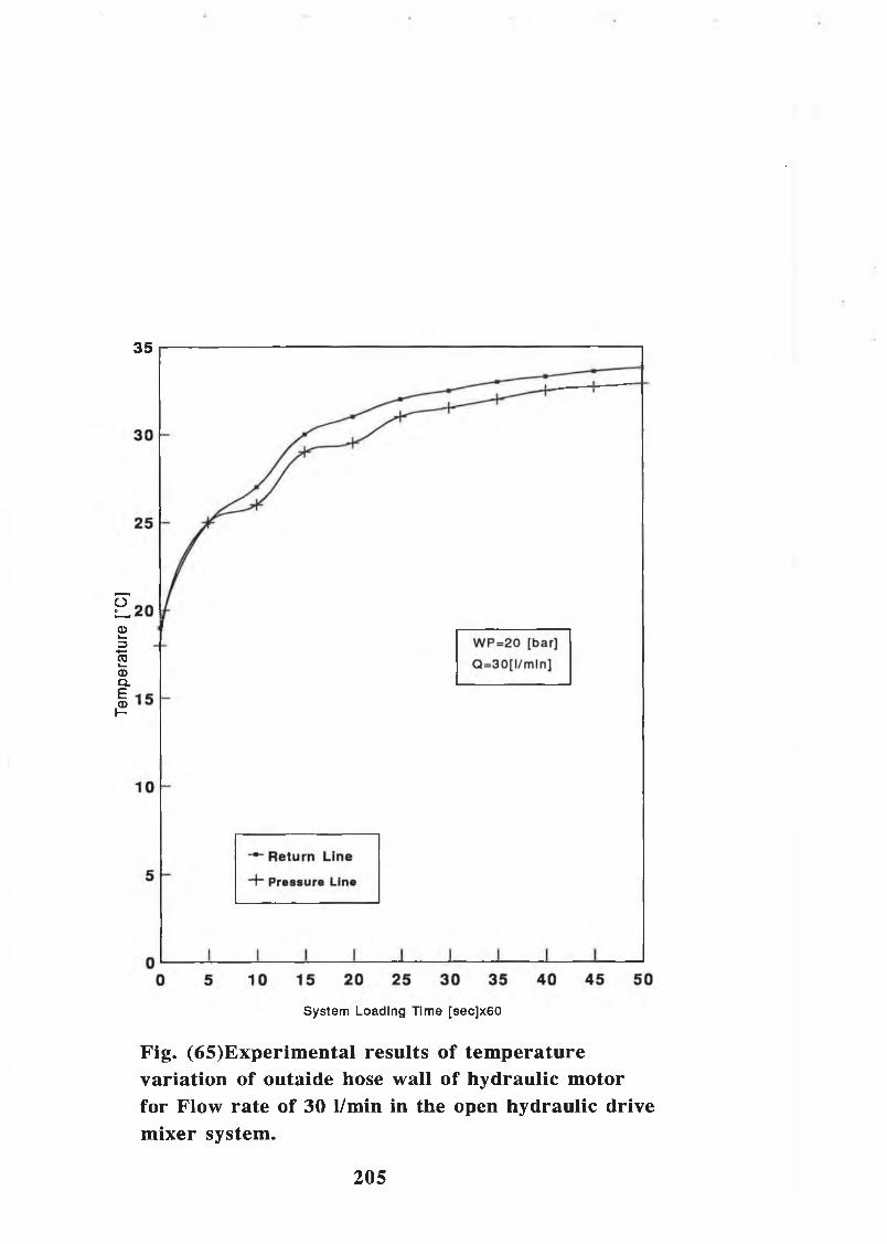
Temp
eratur
e [°C
]
35
System Loading Time [sec]x60
Fig. (65)Experimental results of temperature variation of outaide hose wall of hydraulic motor for Flow rate of 30 1/min in the open hydraulic drive mixer system.
205

40
— Return Line
+ Pressure Line
0 5 10 15 20 25 30 35 40 45 50
System Loading Time [sec]x60
Fig. (66) Experimental results of temperature variation of the outside hose wall of the hydraulic motor for flow rate of 25 1/min. in the open hydraulic drive mixer system.
206
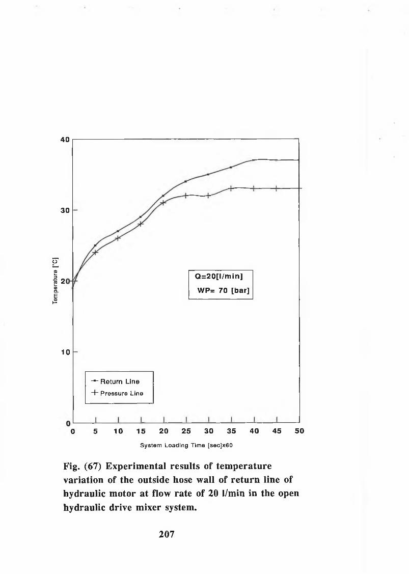
Tem
pera
ture
[°
C]
40
30
2
10
— Return Lin e
+ Pressure Line
Q=20[l/min]
WP= 70 [bar]
0 5 10 15 20 25 30 35 40 45 50
System Loading Time [sec]x60
Fig. (67) Experimental results of temperature variation of the outside hose wall of return line of hydraulic motor at flow rate of 20 1/min in the open hydraulic drive mixer system.
207

System Loading Time [sec]x60
Fig. (68) Experimental results of temperature variation of outside hose wall of hydraulic motor for flow rate of 10 1/min in the open hydraulic drive mixer system.
208

System Loading Time [sec]x60
Fig. (69) Experimental results o f temperature variation ofoutside hose wall o f hydraulic motor for flow rate o f 5 1/min inthe open hydraulic drive mixer system.
209
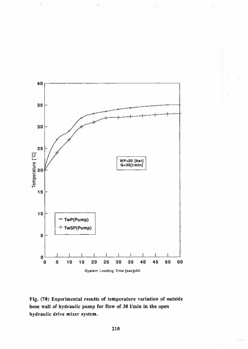
System Loading Time [sec]x60
Fig. (70) Experimental results of temperature variation of outsidehose wall of hydraulic pump for flow of 30 l/min in the openhydraulic drive mixer system.
210

System Loading Time [sec]x60
Fig. (71) Experimental results of temperature variation of outsidehose wall of hydraulic pump for flow rate of 25 1/min in the openhydraulic drive mixer system.

System Loading Time [sec]x60
Fig. (72) Experimental results of temperature variation ofoutside hose wall of hydraulic pump for flow rate of 20 1/min inthe open hydraulic drive mixer system.

80
— TwP(Pump)
+ TwSP(Pump)
0 5 10 15 20 25 30 35 40 45 50 55 60
System Loading Time [sec]x60
Fig. (73) Experimental results of temperature variation of outside hose wall of hydraulic pump for flow rate of 10 1/min in the open hydraulic drive mixer system.
213

80
60
O©L—
is 40CD CLE,<u
Q=5 [l/m in ] WP= 140 [bar]
20
Pressure Line
- f - S uction Line
1 1 I _L I 1 ± JL10 15 20 25 30 35 40 45 50 55 60
System Loading Time [sec]x60
Fig. (74) Experimental results of temperature variation of outside hose wall of hydraulic pump for flow rate of 5 l/min in the open hydraulic drive mixer system.
214

Temp
eratur
e [*C
]
System Loading Time Sec.x 60
Fig. (75) Experimental results of temperature variation of fluidfor flow rate of 30 1/min in the open hydraulic drive mixer system
215

Tem
pera
ture
[°
C]
System Loading Time Sec.x 60
Fig. (76) Experimental results of temperature variation of fluidfor flow rate of 25 1/min in the open hydraulic drive mixer system
216

Tem
pera
ture
[°
C]
System Loading Time Sec.x 60
Fig. (77) Experimental results of temperature variation of fluidfor flow rate of 20 I/min in the open hydraulic drive mixer system
217
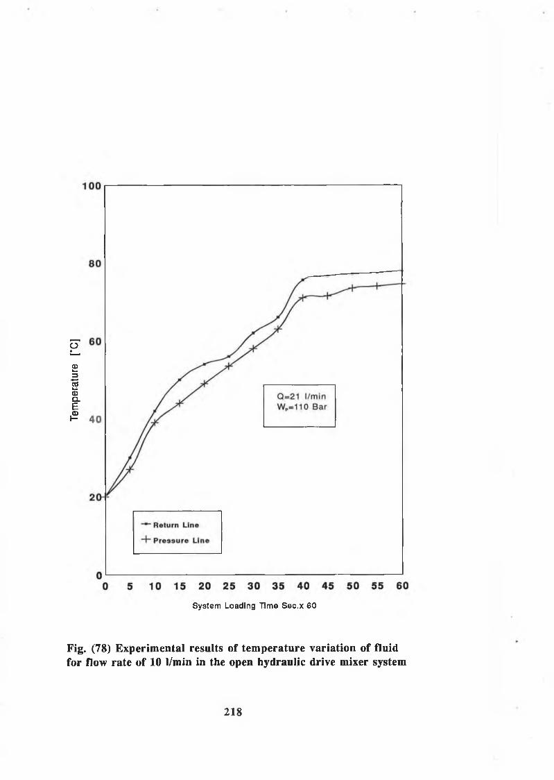
Tem
pera
ture
[*
C]
System Loading Time Sec.x 60
Fig. (78) Experimental results of temperature variation of fluidfor flow rate of 10 1/min in the open hydraulic drive mixer system
218
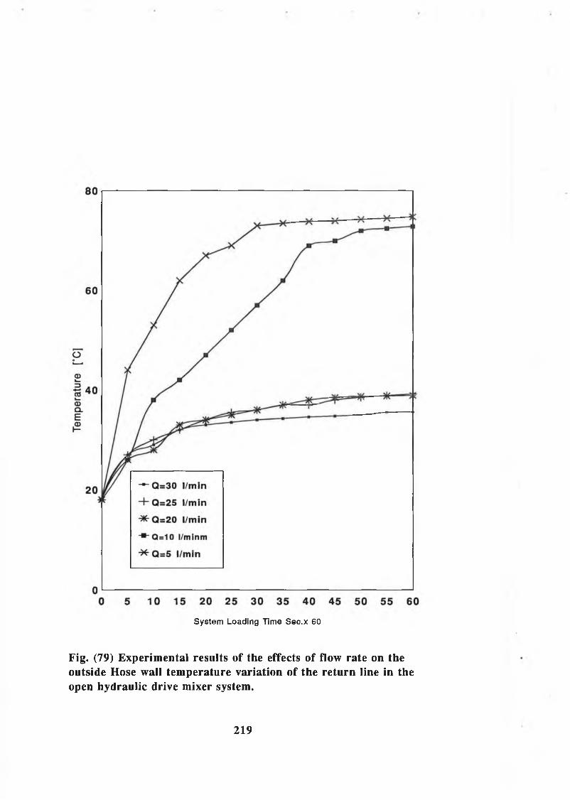
System Loading Time Sec.x 60
Fig. (79) Experimental results of the effects of flow rate on theoutside Hose wall temperature variation of the return line in theopen hydraulic drive mixer system.
219
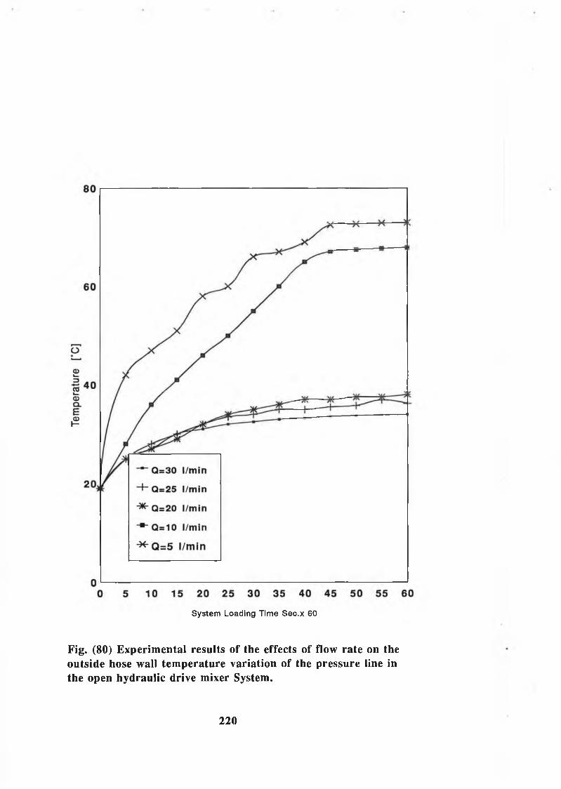
System Loading Time Sec.x 60
Fig. (80) Experimental results of the effects of flow rate on theoutside hose wall temperature variation of the pressure line inthe open hydraulic drive mixer System.
220
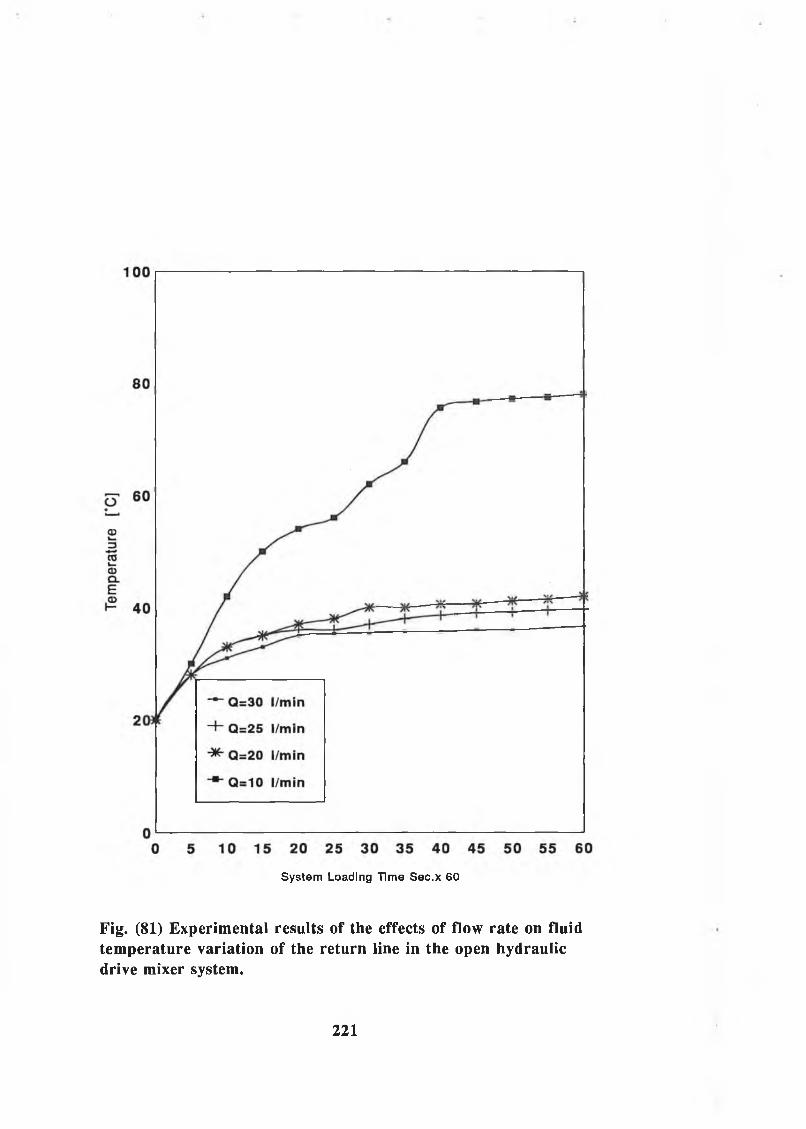
System Loading Time Sec.x 60
Fig. (81) Experimental results of the effects of flow rate on fluidtemperature variation of the return line in the open hydraulicdrive mixer system.
221

System Loading Time Sec.x 60
Fig. (82) Experimental results of the effects of flow rate on fluidtemperature variation of the pressure line in the open hydraulicdrive mixer system.
222
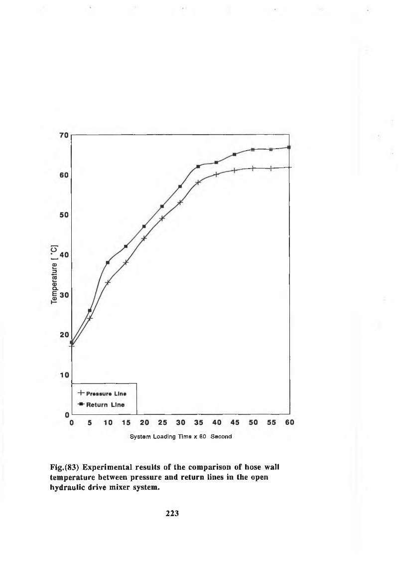
System Loading Time x 60 Second
Fig.(83) Experimental results of the comparison of hose walltemperature between pressure and return lines in the openhydraulic drive mixer system.
223

System Loading Time x 60 Second
Fig.(84) Experimental results of fluid temperatures variation inthe open hydraulic drive mixer system.
224

System Loading Time x 60 Second
Fig.(85) Experimental results of the comparison of hose walltemperatures in the high pressure line of the open hydraulicdrive mixer system.
225
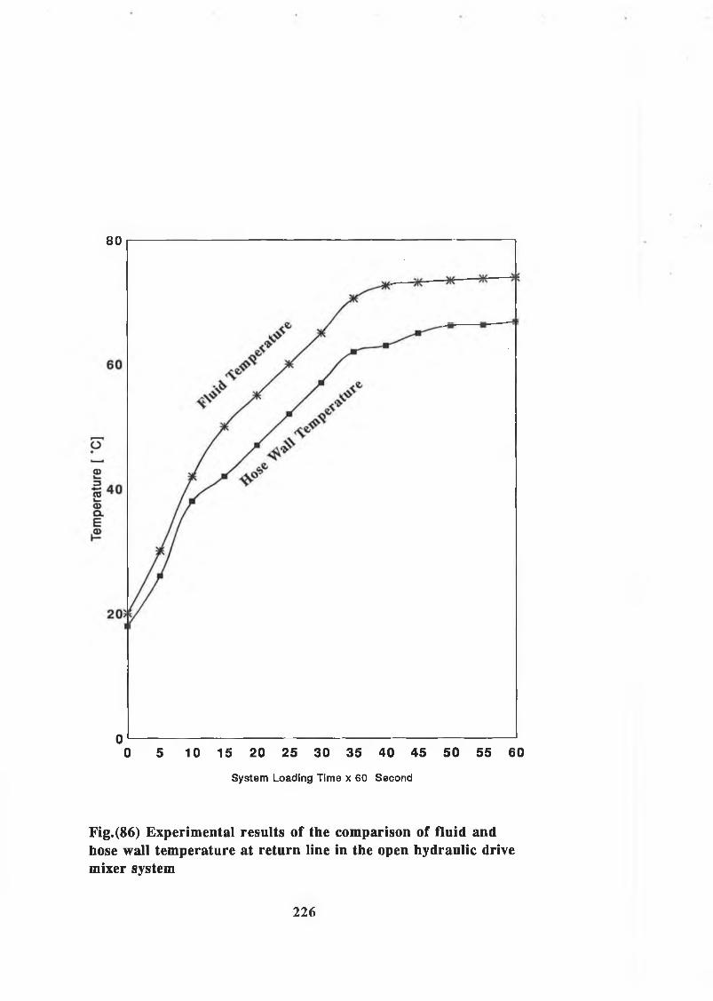
80
0 i---------------------------------------------------------------------------------------------------0 5 10 15 20 25 30 35 40 45 50 55 60
System Loading Time x 60 Second
Fig.(86) Experimental results of the comparison of fluid andhose wall temperature at return line in the open hydraulic drivemixer system
226

System Loading Time x 60 Second
Fig.(87) Experimental results of the comparison of fluid andhose wall temperature at high pressure pipe line in the openhydraulic drive mixer system
227

Tem
pera
ture
[
°C]
System Loading Time x 60 Second
Fig.(88) Experimental results of hoses wall temperaturesvariation in the open hydraulic drive mixer system.
228
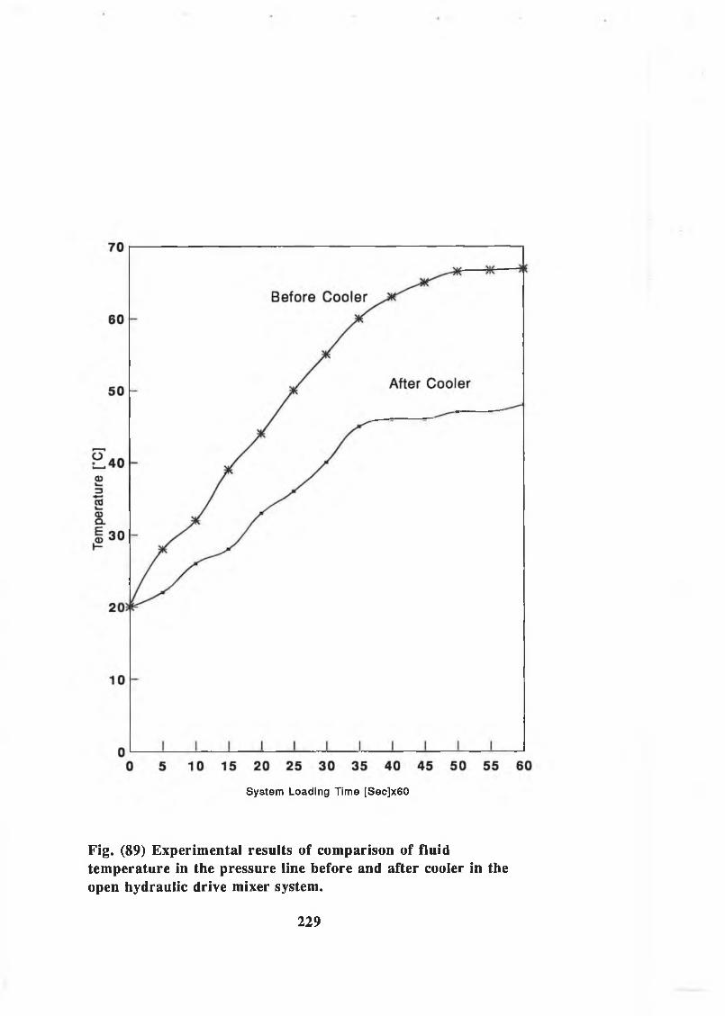
System Loading Time [Sec]x60
Fig. (89) Experimental results of comparison of fluidtemperature in the pressure line before and after cooler in theopen hydraulic drive mixer system.
229
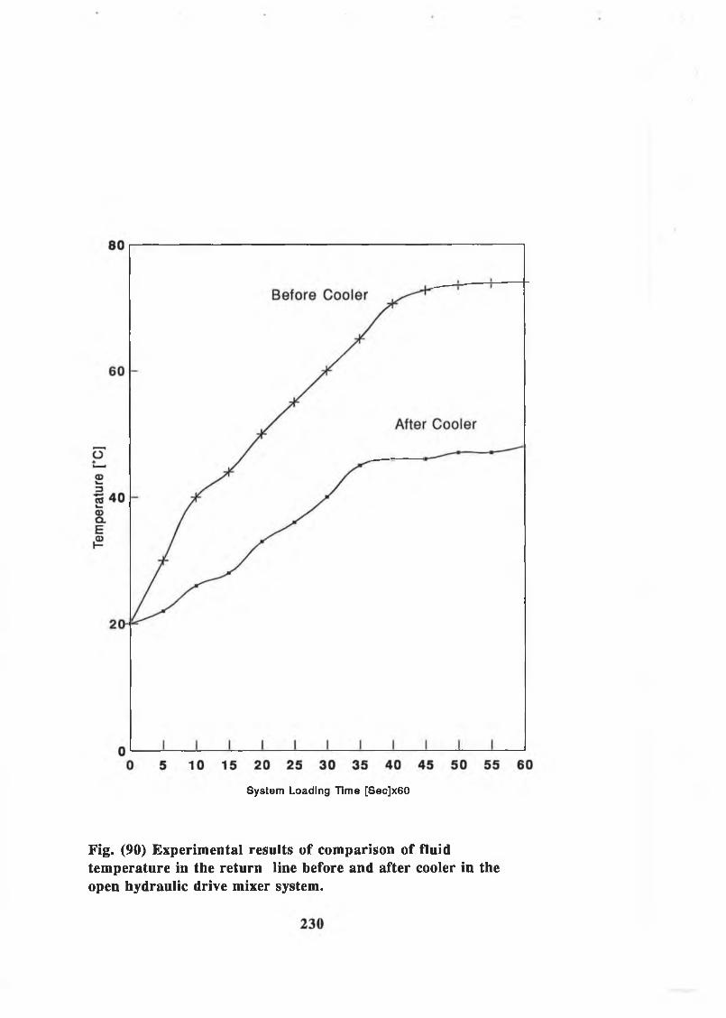
System Loading Time [Sec]x60
Fig. (90) Experimental results of comparison of fluidtemperature in the return line before and after cooler in theopen hydraulic drive mixer system.

System Loading Time [Sec]x60
Fig. (91) Experimental results of comparison of fluidtemperature between the return line and the Pressure Line Beforeand After cooler in the open hydraulic drive mixer system.
231
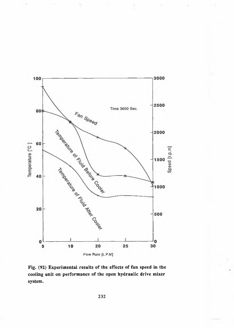
EQ .
T3CUCDQ.co
Flow Rate [L.P.M]
Fig. (92) Experimental results of the effects of fan speed in thecooling unit on performance of the open hydraulic drive mixersystem.
232
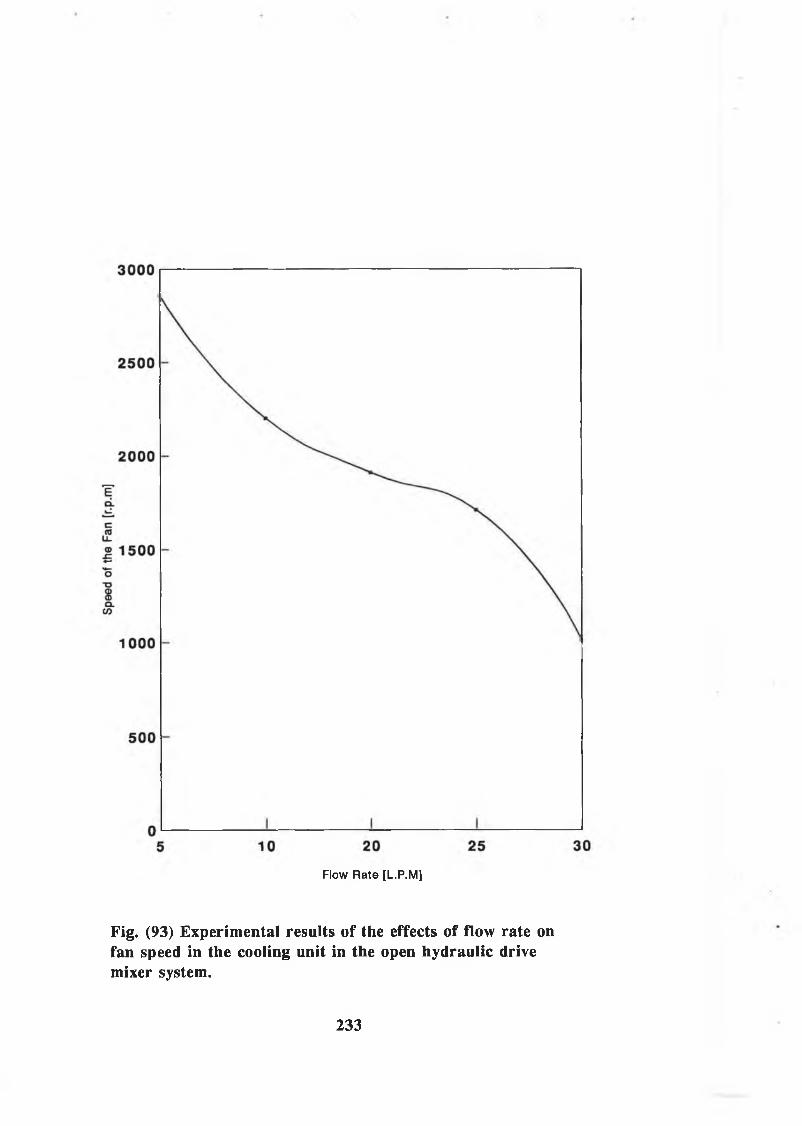
Flow Rate [L.P.M]
Fig. (93) Experimental results of the effects of flow rate onfan speed in the cooling unit in the open hydraulic drivemixer system.
233

work
ing
Pres
sure
[b
ar]
Flow Rate [LPM]
Fig. (94) Experimental results of the effects of flow rate onworking pressure in the open hydraulic drive mixer system.
234

CHAPTER: 5
DISCUSSION
5.1 Discussion on the Theoretical and Experimental Results:
A m a th e m a t ic a l m odel f o r p r e d i c t i n g te m p e r a tu r e
d i s t r i b u t i o n in h y d r a u l i c s y s te m s h a s b een d e v e lo p e d ,
and t h e f e a s i b i l i t y o f p r o v id in g an in e x p e n s i v e but
e f f i c i e n t o i l c o o l e r t o s m a l l s i z e d h y d r a u l i c c i r c u i t
w h ich w i l l r e d u c e r e s e r v o i r s i z e , h e a t p rob lem and w i l l
be an i n t e g r a l p a r t o f t h e c i r c u i t h a s been
i n v e s t i g a t e d . To s tu d y t h e p er fo rm a n ce o f t h e s y s te m , an
e x t e n s i v e e x p e r im e n ta l and t h e o r e t i c a l i n v e s t i g a t i o n h as
b e e n u n d e r ta k e n d u r in g w hich a c o n s i d e r a b l e amount o f
d a t a w ere o b t a i n e d . I n t h i s c h a p t e r , i t i s aimed t o
h i g h l i g h t some o f t h e im p o r ta n t r e s u l t s o b t a in e d
e x p e r i m e n t a l l y and t h e o r e t i c a l l y and t o c a r r y o u t a
co m p a r iso n o f t y p i c a l r e s u l t s .
5.1.1. Discussion on the Procedure and Experimental Results
A number o f i n t e r e s t i n g r e s u l t s h a v e b een o b s e r v e d w h i l e
c a r r y i n g o u t t h e e x p e r im e n ta l t e s t s , u s i n g t h e h y d r a u l i c
d r i v e m ix e r s y s te m . D u rin g t h e c o u r s e o f t h e
e x p e r im e n ta l programme, p a r a m e te r s su c h a s l e n g t h ,
d ia m e te r and m a t e r i a l o f t h e p i p e s , g eo m etry o f t h e
235

r e s e r v o i r and t h e c o o l i n g u n i t w ere v a r i e d in o r d e r t o
i n v e s t i g a t e t h e i r e f f e c t s on t h e p er fo r m a n c e o f t h e
s y s t e m .
Four th e r m o c o u p le s w i t h a d i g i t a l o u t p u t w ere u se d in
t h e s e e x p e r im e n ts t o m easure t h e h o s e w a l l t e m p e r a t u r e s .
F lu id t e m p e r a tu r e in t h e r e s e r v o i r was m easured w i t h a
d i a l mounted gau ge w h ich u s e s a t e m p e r a tu r e s e n s i t i v e
f l u i d t h a t i s m e ta l e n c a s e d and immersed in t h e
h y d r a u l i c f l u i d . Two i n l i n e te m p e r a tu r e m e te r s w ere u se d
t o m easu re t h e t e m p e r a tu r e o f t h e f l u i d f l o w in g th ro u g h
t h e p i p e s . A c t u a l m o to r , pump and fa n s p e e d s w ere
o b t a in e d u s i n g a rem ote h a n d -h e ld d i g i t a l r e a d in g
ta c h o m e te r w h ich m ea su res t h e sp e e d o f a mark r o t a t i n g
w it h t h e o u tp u t s h a f t .
The h y d r a u l i c r e s e r v o i r was f i l l e d w i t h SHELL TELLUS-37
h y d r a u l i c o i l t o t h e l e v e l mark on t h e s i g h t g l a s s . The
s e t t i n g o f r e l i e f v a l v e was a d j u s t e d on 150 b a r . As
m en tio n ed in c h a p t e r tw o , t h e m ix er m echanism was f i l l e d
w it h d i f f e r e n t m a t e r i a l t o g e t d i f f e r e n t l o a d s .
The s y s te m was run f o r on e hour under lo a d i n l e a d i n g
to w a r d s t h e s t e a d y th e r m a l c o n d i t i o n . Changes o f f l u i d
and p ip e w a l l t e m p e r a tu r e s w ere r a p id i n i t i a l l y and t h e
t e m p e r a tu r e r e a d in g s w ere t h e r e f o r e r e c o r d e d e v e r y one
m in u te f o r t h e f i r s t f i v e m in u te s , e v e r y two m in u te s f o r
t h e f o l l o w i n g 25 m in u te s and th e n e v e r y f i v e m in u te s
236

F o l lo w in g c l o s e l y t h e ab ove d i s c u s s e d t e s t p r o c e d u r e , an
e x t e n s i v e t e s t programme was u n d er ta k e n t o v e r i f y t h e
d e v e lo p e d m a th e m a t ic a l m odel and t o i n v e s t i g a t e
e x p e r i m e n t a l l y t h e p o s s i b i l i t y o f p r o v id in g an e f f i c i e n t
o i l c o o l e r t o s m a l l s i z e d h y d r a u l i c c i r c u i t w h ich w i l l
r e d u c e h e a t p r o b le m s , r e s e r v o i r s i z e and w i l l be an
i n t e g r a l p a r t o f t h e c i r c u i t . The t y p i c a l s e t o f
t e m p e r a tu r e r e c o r d i n g s from t h e e x p e r im e n t a l t e s t i s
p r e s e n t e d in F ig . (65) th r o u g h F ig . ( 9 4 ) .
F i g s . (65) t o (74) show t h e m easured t e m p e r a tu r e o f t h e
o u t s i d e h o s e w a l l f o r d i f f e r e n t p a r t o f t h e p i p e l i n e in
t h e c i r c u i t a t d i f f e r e n t f l o w r a t e s . T h ese r e s u l t s show
t h a t t h e r e c o r d e d m easured r a t e o f t e m p e r a tu r e r i s e a t
t h e o u t s i d e h o s e w a l l w ere g r e a t e r d u r in g t h e f i r s t 35
m in u te s o f t h e s y s te m lo a d in g t im e . For s y s te m lo a d in g
t im e i n e x c e s s o f 50 m in u t e s , t h e r e c o r d e d te m p e r a tu r e s
w ere o b se r v e d t o be a p p r o x im a te ly c o n s t a n t due t o t h e
a c h ie v e m e n t o f s t e a d y s t a t e c o n d i t i o n a s shown in F ig .
(70) .
I t h a s b een o b s e r v e d t h a t t h e c o n s t a n t te m p e r a tu r e
v a l u e s o f s t e a d y s t a t e c o n d i t i o n h ave n o t b een a c h ie v e d
in some e x p e r im e n ta l r e s u l t s a s shown i n F i g . ( 8 3 ) . A
p o s s i b l e r e a s o n i s t h e g r a d u a l i n c r e a s e in t h e
a tm o s p h e r ic t e m p e r a tu r e s u r r o u n d in g t o t h e t e s t r i g o v er
t h e d u r a t io n o f t h e t e s t s o f s y s te m l o a d i n g . For
to w a rd s t h e end o f t e s t s .
237
e x a m p le , t h e room te m p e r a tu r e i n t h e l a b o r a t o r y c o u ld be
d i f f e r e n t in a s i n g l e day o r d i f f e r e n t on d i f f e r e n t d ays
o f t h e w eek . M oreover , t h e e x p e r im e n ta l r e s u l t s have
shown t h a t t h e f l u i d te m p e r a tu r e i n t h e se c o n d p a r t o f
t h e p r e s s u r e l i n e i s a p p r o x im a te ly 3 °C h i g h e r th a n t h a t
r e c o r d e d a t t h e f i r s t p a r t o f t h e h ig h p r e s s u r e l i n e a s
shown in F i g . (84) . The r e a s o n c o u ld be t h e w e l l known
t e m p e r a t u r e - p r e s s u r e drop c o e f f i c i e n t 5 °C /100 b a r , s e e
R e f . 4 8 , i n a p ip e l i n e . S i m i l a r l y , F i g . (88) shows t h a t
t h e maximum d i f f e r e n c e b e tw een t h e m easured w a l l
t e m p e r a tu r e s i n t h e d i f f e r e n t p a r t s o f t h e p i p e l i n e i s
a b o u t 7 °C. T h is i s due t o p r e s s u r e drop th o r o u g h th e
f i t t i n g s and t h e e r r o r s i n t h e te m p e r a tu r e m easu rem en ts .
The t e m p e r a tu r e r e s u l t s o b t a in e d e x p e r i m e n t a l l y from
d i f f e r e n t p a r t s o f t h e s y s te m show a s i g n i f i c a n t
d i f f e r e n c e b e tw een f l u i d and p ip e w a l l t e m p e r a tu r e .
T h ese te m p e r a tu r e d i f f e r e n c e s can n o t be ig n o r e d even i f
t h e e x p e r im e n ta l m easurem ent e r r o r s h a v e b e e n ta k e n i n t o
a c c o u n t , t y p i c a l ex a m p le s a r e shown i n F i g s (86) and
(87) .
S in c e t h e h y d r a u l i c r e s e r v o i r i n t h e c o n v e n t io n a l open
h y d r a u l i c s y s te m r e q u i r e s a l a r g e s i z e and s p a c e and t h e
e n e r g y consum ing b o o s t pump in t h e c l o s e d h y d r a u l i c
s y s te m r e q u i r e s an a d d i t i o n a l d r i v i n g pow er, n e i t h e r t h e
t r a d i t i o n a l open h y d r a u l i c s y s te m nor t h e c l o s e d
h y d r a u l i c s y s te m may be t h e b e s t d e s ig n c h o i c e under
238
su ch s p e c i a l w ork in g c o n d i t i o n s . In t h i s r e s e a r c h an
e x t e n s i v e programme o f e x p e r im e n ta l t e s t s h a v e been
c a r r i e d o u t t o i n v e s t i g a t e t h e p o s s i b i l i t y o f u s i n g an
e f f i c i e n t o i l c o o l e r a s an i n t e g r a l p a r t o f t h e
h y d r a u l i c c i r c u i t t o s m a l l s i z e d h y d r a u l i c s y s t e m s w hich
w i l l r e d u c e h e a t p ro b lem s and r e s e r v o i r s i z e in th e
c o n v e n t io n a l open h y d r a u l i c s y s t e m s . The t y p i c a l s e t s o f
t e m p e r a tu r e r e c o r d i n g s from t h e e x p e r im e n ta l t e s t i s
p r e s e n t e d i n F ig . (89) t o F i g . ( 9 4 ) .
T h ese e x p e r im e n ta l r e s u l t s h ave shown t h a t t h e
t e m p e r a tu r e w ould be d e c r e a s e d by b etw een 25 t o 3 5 °C
th r o u g h u s i n g t h e o i l c o o l i n g u n i t a s an i n t e g r a l p a r t
o f t h e h y d r a u l i c c i r c u i t . T y p ic a l ex a m p le s a r e g i v e n in
F i g s 8 9 , 90 and 9 1 . As can be s e e n in F i g . (89) t h e
te m p e r a tu r e i n t h e s y s te m b e f o r e t h e c o o l e r i s a b o u t 70
°C w h ich i s a b o u t 10 °C h ig h e r th a n t h a t recommended,
b u t a f t e r t h e o i l c o o l e r t h e te m p e r a tu r e i s a b o u t 45 °C.
T hat means by u s i n g t h e o i l c o o l e r t h e te m p e r a tu r e
d e c r e a s e s by ab o u t 25 °C w h i l e F i g . (91) s u g g e s t s t h a t
by u s i n g t h e c o o l i n g u n i t , t h e t e m p e r a tu r e c o u ld be
r e d u c e d by 4 0 %. As a c o m p a r iso n , u n d er t h e same
c o n d i t i o n w here t h e e l e c t r i c m otor i s o p e r a t e d a t a
n o m in a l sp e e d o f 1500 r . p . m . , t h e r e s e r v o i r c a p a c i t y in
a c o n v e n t io n a l open s y s te m i s n o r m a lly c h o se n a s 6 t o 7
t im e s o f t h e s y s te m f l o w r a t e . T h is means t h a t a 48 t o 56
c a p a c i t y l i t r e s r e s e r v o i r h a s t o be u s e d .
239

5.1.2. Discussion on the Analysis, Simulation Package and
Theoretical Results
A m a th e m a t ic a l m odel h a s b een d e v e lo p e d i n o r d e r t o
s tu d y t h e te m p e r a tu r e b e h a v io u r i n any h y d r a u l i c s y s te m .
The m a th e m a t ic a l m odel i s d e v e lo p e d t o c o n s id e r a
h y d r a u l i c s y s te m (su c h a s t h e open h y d r a u l i c d r i v e m ix er
sy s te m ) a s an open th e r m a l s y s te m w i t h t h e a s su m p tio n
t h a t t h e t e m p e r a tu r e s o f f l u i d and p ip e w a l l a r e
u n ifo r m . In a d d i t i o n , t h e s y s te m main lo o p i s c o n s id e r e d
a s an open th e r m a l s y s te m w here u n ifo rm te m p e r a tu r e i s
assum ed t o r e p r e s e n t t h e lo o p f l u i d t e m p e r a tu r e , w h i l e
t h e r e s e r v o i r i s a n o th e r open th e r m a l s y s t e m . However,
i f t h e te m p e r a tu r e in one p a r t o f t h e lo o p s i g n i f i c a n t l y
d i f f e r s from a n o th e r p a r t in a h y d r a u l i c s y s t e m , t h e
a ssu m p t io n o f u n ifo rm lo o p f l u i d te m p e r a tu r e i n t h e
p r e s e n t a n a l y s i s can no lo n g e r be a p p l i e d . The r e s u l t s
may im proved by r e g a r d in g t h e s y s te m lo o p a s a s e r i e s o f
open th e r m a l s y s t e m s w i t h a c o n s t a n t f l u i d te m p e r a tu r e
in e a c h s e c t i o n o f t h e s y s t e m . In t h i s way, an open
th e r m a l s y s te m o f a p ip e s e c t i o n can be a p p l i e d f o r
t h e o r e t i c a l s o l u t i o n o f t h e f l u i d t e m p e r a tu r e s a t t h e
d i f f e r e n t p a r t o f t h e s y s t e m . The p r i n c i p l e o f t h i s
s u g g e s t i o n i s t o d e v e lo p a s e r i e s o f f l u i d t e m p e r a tu r e
m o d els f o r t h e d i f f e r e n t s e c t i o n s o f p ip e i n t h e sy s te m ,
t h e n f l u i d t e m p e r a tu r e i n e a c h p a r t i c u l a r s e c t i o n o f t h e
p ip e can be e s t im a t e d s e p a r a t e l y .
240

S o f tw a r e h a s b een d e v e lo p e d i n c o r p o r a t in g t h e above
a n a l y s i s i n o r d e r t o p r e d i c t t h e t r a n s i e n t f l u i d and
p ip e w a l l t e m p e r a tu r e s o f any h y d r a u l i c s y s te m under
u n s te a d y s t a t e c o n d i t i o n s . T h is program i s e s p e c i a l l y
s u i t a b l e t o s im u l a t e f l u i d power s y s t e m , t h e main aims
o f t h i s program a r e :
( i ) To p r o v id e a com puter a id e d d e s ig n t o o l w h ich can be
u se d by an i n d u s t r i a l e n g in e e r o r r e s e a r c h e r w i t h v e r y
l i t t l e k n ow led ge o f com puter s y s t e m s .
( i i ) To p r o v id e a f a c i l i t y w h ich a l l o w s c h a n g e s in
com ponent p a r a m e te r s o r i n c i r c u i t c o n f i g u r a t i o n t o be
c a r r i e d o u t w i t h o u t f u r t h e r n eed f o r program m ing.
( i i i ) To p r o v id e a f a c i l i t y w h ich a l l o w s a d d in g new
com ponents w i t h o u t any m o d i f i c a t i o n i n t h e programme.
F i g . (30) e x p l a i n s in d e t a i l s t h e c o m p le te sy s tem
s i m u l a t i o n d iagram .
In t h i s r e s e a r c h t h e s i m u l a t i o n s w ere c a r r i e d o u t f o r
a n a l y z i n g a l a r g e number o f 60 m in u te s d u r a t io n
e x p e r im e n t a l t e m p e r a tu r e t e s t s d u r in g t h e sy s te m
l o a d i n g . As i n t h e e x p e r im e n ts t h e s y s te m i s c o n s id e r e d
t o be c o n s t r u c t e d by t h e same s i z e o f p i p e s and p ip e
w a l l m a t e r i a l . H owever, a u n ifo r m f l u i d te m p e r a tu r e
th r o u g h o u t t h e s y s te m lo o p and r e s e r v o i r was assum ed in
t h e s i m u l a t i o n . The s im u l a t i o n r e s u l t s a r e shown from
F i g s . (31) t o F i g . (63) and d i s c u s s e d p r e v i o u s l y , b u t
241
h e r e a r e t h e m ain p o i n t s .
The m a g n itu d e o f t h e i n s i d e d ia m e te r o f p i p e i s more
i n f l u e n t i a l on f l u i d te m p e r a tu r e th a n o u t s i d e p ip e w a l l
te m p e r a tu r e (S ee F ig s 3 5 and 36) . T h is i s b e c a u s e t h e
r e d u c t i o n i n t h e i n t e r n a l p i p e d ia m e te r r e d u c e s t h e p ip e
i n t e r n a l s u r f a c e a r e a and a t t h e same t im e i n c r e a s e s t h e
h e a t c o e f f i c i e n t by f o r c e d c o n v e c t i o n . H ence , th e
com bined e f f e c t s c a n c e l t h e e f f e c t o f t h e ch an ge in
d ia m e t e r . However, t h e s i z e o f t h e p ip e o u t s i d e d ia m e te r
h a s c o n s i d e r a b l e i n f l u e n c e on t h e p ip e w a l l te m p e r a tu r e
a s shown in F i g . ( 3 7 ) .
The s i m u l a t i o n r e s u l t s h a v e shown t h a t t h e t y p e o f p ip e
w a l l m a t e r i a l p l a y s an im p o r ta n t r o l e i n d e t e r m in in g t h e
t e m p e r a tu r e d i s t r i b u t i o n s i n c e t h e m agn itu d e o f p ip e
w a l l s p e c i f i c h e a t , d e n s i t y and th e r m a l c o n d u c t i v i t y a r e
d ep en d a n t on t h e p ip e w a l l m a t e r i a l (S ee F i g s . 3 9 t o
44) . The s i m u l a t i o n r e s u l t s h a v e a l s o shown a l a r g e
d i f f e r e n c e b etw een t h e o u t s i d e p ip e w a l l t e m p e r a tu r e o f
s t e e l o r co p p er p i p e s and ru b b er h o s e a s shown i n F ig s
47 and 48 a s i t w ould be e x p e c t e d due t o a b ig
d i f f e r e n c e w h ich e x i s t s b e tw een t h e th erm a l
c o n d u c t i v i t i e s o f m e t a l l i c and n o n - m e t a l l i c m a t e r i a l . An
i n t e r e s t i n g phenomenon shown i n t h e s i m u l a t i o n f l u i d
t e m p e r a t u r e s and i l l u s t r a t e d i n F i g s . (47) and (48) , i s
t h a t f l u i d te m p e r a tu r e i n t h e s y s te m w i t h t h e s t e e l or
co p p e r p i p e l i n e i s h ig h e r th a n t h a t i n t h e s y s te m w ith
242

t h e h y d r a u l i c h o s e . T h ese s i m u l a t i o n f l u i d t e m p e r a tu r e s
h a v e r e s u l t e d when t h e e f f e c t s o f r a d i a t i o n and
c o n d u c t io n w ere ta k e n i n t o a c c o u n t .
D e s p i t e t h e f a c t t h a t t h e th e r m a l c o n d u c t i v i t i e s o f
s t e e l and co p p er p i p e s a r e much h ig h e r th a n t h a t o f
ru b b er o r h o s e , t h e e m i s s i v i t y o f s t e e l and co p p er a r e
lo w e r th a n t h a t o f ru b b er h o s e a s d a ta i n d i c a t e d in
T a b le (15) . T h is co m p a r iso n o f s im u l a t i o n f l u i d
t e m p e r a tu r e r e s u l t s s h o u ld q u e s t i o n t h e w id e ly a c c e p t e d
a ssu m p tio n i n many l i t e r a t u r e in w h ich t h e r a d i a t i o n
e f f e c t under 2 00 °C i s ig n o r e d .
A number o f s i m u l a t i o n s h a v e b een c a r r i e d o u t t o
i n v e s t i g a t e t h e e f f e c t o f r e s e r v o i r g eo m etry on t h e
t e m p e r a tu r e d i s t r i b u t i o n . The r e s u l t s h ave shown t h a t
t h e f l u i d h e i g h t i n t h e r e s e r v o i r , and t h e l e n g t h and
w id th o f t h e r e s e r v o i r h a v e i n f l u e n c e on t h e f l u i d
te m p e r a tu r e o f t h e r e s e r v o i r and t h e s y s te m lo o p a s
i n d i c a t e d in F i g s . (49) t o ( 5 4 ) .
5.2. Comparative Performance of the Hydraulic Systems: F ig .
(95) shows t h e co m p a r iso n b etw een t h e f l u i d and h o se
w a l l t e m p e r a tu r e o b t a in e d e x p e r i m e n t a l l y . T h is f i g u r e
show s c o n s i d e r a b l e d i f f e r e n c e b e tw een t h e f l u i d and h o se
w a l l t e m p e r a tu r e s where t h e h o s e w a l l t e m p e r a tu r e i s
p r e d i c t e d t o be a b o u t 6 °C lo w e r th a n t h e f l u i d
243

t e m p e r a t u r e . T h is d i f f e r e n c e b e tw een t h e f l u i d and h o s e
w a l l t e m p e r a tu r e i s beyond t h e l e v e l o f e x p e r im e n ta l
e r r o r . The r e s u l t s o b t a in e d e x p e r i m e n t a l l y , show good
agreem en t w i t h t h e t h e o r e t i c a l r e s u l t s .
F i g . (96) show s t h e co m p a r iso n b e tw een t h e e x p e r im e n ta l
and t h e o r e t i c a l f l u i d te m p e r a tu r e i n t h e p r e s s u r e p ip e
l i n e . In t h i s f i g u r e a c l o s e a g reem en t b e tw een t h e o r y
and e x p e r im e n t i s o b s e r v e d . F i g . (97) shows t h e
co m p a r iso n b etw een e x p e r im e n ta l and t h e o r e t i c a l r e s u l t s
o f t h e h o s e w a l l t e m p e r a tu r e . T h is f i g u r e a l s o shows
s i m i l a r t r e n d a s t h a t i n F ig u r e ( 9 6 ) .
Com parison h a s shown a s i g n i f i c a n t d i f f e r e n c e b etw een
t h e r e s u l t s p r e d i c t e d a c c o r d in g t o r e f e r e n c e (15) and
t h o s e p r e d i c t e d u s i n g t h e p r e s e n t m a th e m a t ic a l m od el.
A c c o r d in g t o R e fe r e n c e (15) i n w h ich t h e e f f e c t o f h e a t
t r a n s f e r r e d by c o n d u c t io n in t h e h y d r a u l i c s y s te m and by
r a d i a t i o n from t h e s u r f a c e s o f t h e r e s e r v o i r w ere
ig n o r e d , a c o n s i d e r a b l e d i f f e r e n c e i n t h e e s t i m a t e o f
t h e te m p e r a tu r e d i s t r i b u t i o n i n t h e h y d r a u l i c s y s t e m s i s
s u g g e s t e d . T y p ic a l exam p les a r e g i v e n in F ig s (98) and
(99) . F i g . (98) shows t h e co m p a r iso n o f t h e f l u i d
te m p e r a tu r e p r e d i c t e d a c c o r d in g t o t h e p r e s e n t a n a l y s i s
and t h e a n a l y s i s i n R e fe r e n c e (15) w i th t h a t o b t a in e d
e x p e r i m e n t a l l y . T h is f i g u r e shows a c l o s e r agreem en t
b etw een t h e e x p e r im e n ta l r e s u l t s and t h e o r e t i c a l r e s u l t s
p r e d i c t e d a c c o r d in g t o t h e p r e s e n t a n a l y s i s w hich
244

s l i g h t l y o v e r e s t i m a t e s t h e t e m p e r a tu r e r i s e . F ig . (99)
show s t h e same t r e n d a s t h a t i n F i g . (98) . i n r e s p e c t o f
t h e p ip e w a l l t e m p e r a tu r e .
245
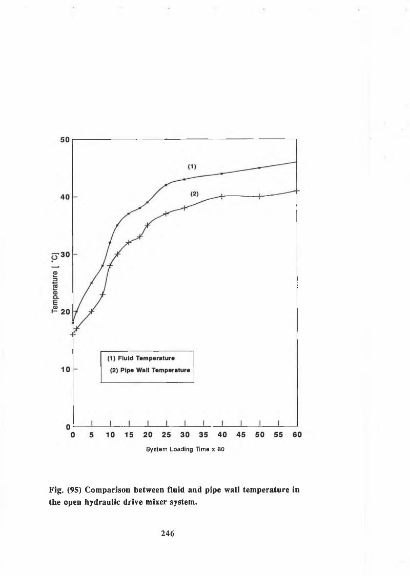
System Loading Time x 60
Fig. (95) Comparison between fluid and pipe wall temperature inthe open hydraulic drive mixer system.
246

System Loading Time x 60
Fig. (96) Comparison between experimental and theoreticalresults of fluid temperature in the pressure line in the openhydraulic drive mixer system.
247

System Loading Time x 60
Fig. (97) Comparison between experimental and theoreticalresults of hose wall temperature in the pressure line in the openhydraulic drive mixer system.
248

System Loading Time x 60
Fig. (98) Comparison of the fluid temperature between thepresent analysis and the analysis in Reference (15) in the openhydraulic drive mixer system.

System Loading Time x 60
Fig. (99) Comparison of the outside wall temperature of the hosebetween the present analysis and the analysis in Reference (15)in the open hydraulic drive mixer system.
250
CHAPTER: 6
Conclusion and Suggestion for Future Work
6.1 ConclusionIn t h i s t h e s i s a m a th e m a t ic a l m odel f o r te m p e r a tu r e
d i s t r i b u t i o n in h y d r a u l i c s y s t e m s h a s b een d e v e lo p e d . The
h e a t t r a n s f e r r e d by c o n d u c t io n , c o n v e c t i o n and r a d i a t i o n
h a v e b een ta k e n i n t o a c c o u n t . A s tu d y o f therm odynam ic
b e h a v io u r o f t h e h y d r a u l i c d r i v e m ix er s y s te m h a s l e d th e
way t o d e v e lo p t h i s m a th e m a t ic a l m odel f o r te m p e r a tu r e
p r e d i c t i o n i n h y d r a u l i c s y s t e m s . In t h i s a n a l y s i s t h e h e a t
t r a n s f e r b e tw een t h e f l u i d and p ip e w a l l s h a v e b een ta k e n
i n t o a c c o u n t . T h is a n a l y s i s can be a p p l i e d t o s im u la t e
therm odynam ic b e h a v io u r o f o t h e r h y d r a u l i c s y s t e m s . The
s i m u l a t i o n r e s u l t s h a v e shown t h a t a c o n s id e r a b l e
d i f f e r e n c e e x i s t s b e tw een t h e f l u i d and p ip e w a l l
t e m p e r a t u r e s i n t h e h y d r a u l i c s y s t e m . A p a r t i c u l a r
i n t e r e s t i n g d e v e lo p m e n t o f t h e work h a s b een th e
s i m u l a t i o n i n v e s t i g a t i o n s o f r a d i a t i o n e f f e c t s under room
te m p e r a tu r e c o n d i t i o n . On t h e b a s i s o f t h e work i t h as
b een c o n c lu d e d t h a t t h e r a d i a t i o n e f f e c t s i n t h e r e g io n
c o n s id e r e d a r e f a r more s i g n i f i c a n t th a n p r e v i o u s l y
251
t h o u g h t . T h is h a s q u e s t i o n e d t h e w i d e l y a c c e p te d
a ssu m p t io n i n su c h many p r e v i o u s l i t e r a t u r e w h ich ig n o r e s
t h e r a d i a t i o n e f f e c t s u n d er 200 °C.
N u m er ica l i n t e g r a t i o n t e c h n iq u e h ave b een u se d i n t h i s
work t o s o l v e t h e v a r i o u s e q u a t io n s f o r m u la te d in t h e
m a th e m a t ic a l model t o p r e d i c t t h e p er fo rm a n ce o f h y d r a u l i c
s y s t e m s in term s o f t h e te m p e r a tu r e d i s t r i b u t i o n in
h y d r a u l i c s y s t e m s u n d er u n s te a d y s t a t e c o n d i t i o n s .
The s tu d y o f t h e t e m p e r a tu r e b e h a v io u r o f a h y d r a u l i c
s y s te m i s o f p a r t i c u l a r im p o rta n ce when s a v in g s in sp a c e
and e n e r g y a r e b e in g c o n s id e r e d . A d i g i t a l com puter
s i m u l a t i o n p a ck a g e h a s b een d e v e lo p e d t o be u se d in
h y d r a u l i c s y s te m d e s i g n . The main a d v a n ta g e o f t h i s
p a ck a g e i s t h a t i t i s u s e r f r i e n d l y and v e r y l i t t l e p r i o r
programming s k i l l i s n e e d e d . T h is P ackage e n a b le s th e
h y d r a u l i c e n g in e e r t o a l t e r s y s te m p a r a m e te r s and
d e te r m in e t h e r e s u l t i n g s y s te m r e s p o n s e i n a r e l a t i v e l y
c h e a p e r , q u ic k e r and s a f e r way th a n p r a c t i c a l t e s t i n g
w ou ld a l l o w .
In t h i s r e s e a r c h an e x t e n s i v e programme o f e x p e r im e n ta l
t e s t s h a s b een done t o i n v e s t i g a t e t h e v a l i d i t y o f t h e
m a th e m a t ic a l m odel and t o i n v e s t i g a t e t h e f e a s i b i l i t y o f
p r o v i d i n g a c o o l i n g u n i t a s an i n t e g r a l p a r t in t h e
c i r c u i t o f t h e h y d r a u l i c s y s t e m s . The e x p e r im e n ta l r e s u l t s
252

have shown t h a t t h e t e m p e r a tu r e c o u ld be r e d u c e d by about
40 % o f t h e w ork in g t e m p e r a tu r e and, t h a t t h e te m p e r a tu r e
can a lw a y s be k e p t b e lo w t h e recommended l e v e l w hich i s
b etw een 50 - 60 °C. In a d d i t i o n , t h e main r e s u l t o f th e
e x p e r im e n ts h a s shown t h a t t h e h y d r a u l i c r e s e r v o i r i s
r e d u c e d in t h e s i z e by 6 t o 8 t im e s t h a t o f t h e
c o n v e n t io n a l r e s e r v o i r n o r m a lly n eed ed i n t h e open
h y d r a u l i c s y s t e m s .
The s i m u l a t i o n s d e s c r i b e d i n t h i s t h e s i s h a v e shown
s u f f i c i e n t l y c l o s e a g reem en t w i t h t h e e x p e r im e n ts t o
v a l i d a t e t h e m a th e m a t ic a l m o d e ls . They h a v e b een u se d t o
g i v e f u l l e x p l a n a t i o n o f t h e b e h a v io u r o f t h e sy ste m
c o n s id e r e d . They can be a l s o u se d t o be an e f f e c t i v e
d e s i g n t o o l f o r t h e s y s te m com ponents i n c l u d i n g c o o l e r ,
f i l t e r and r e s e r v o i r s i z i n g .
I t can be s e e n from t h e e x a m in a t io n o f te m p e r a tu r e
s i m u l a t i o n s and c o r r e s p o n d in g e x p e r im e n ta l r e s u l t s t h a t
t h e t h e o r e t i c a l a n a l y s i s h a v e b een im p lem en ted i n t o t h e
d e v e lo p e d s o f t w a r e p a ck a g e and h e n c e t h e y can be im proved
t o c o v e r te m p e r a tu r e m o d e l l in g in o t h e r more com plex
h y d r a u l i c s y s t e m s .
6.2. Suggestions for Future Work
The performance of an open hydraulic system with compact
253
s i z e o f t h e r e s e r v o i r h a s b een t e s t e d e x p e r i m e n t a l l y . In
t h e a n a l y s i s i t was a t te m p te d t o in c o r p o r a t e a s many
f a c t o r s a s p o s s i b l e . However, f u r t h e r work c o u ld u s e f u l l y
b e c o n d u c te d i n t h e f o l l o w i n g a r e a s .
6.2.1. Theoretically
The m a th e m a t ic a l m o d e ls h a v e b een d e v e lo p e d b a se d on t h e
a ssu m p t io n t h a t u n ifo rm te m p e r a tu r e i s r e p r e s e n t e d in t h e
lo o p f l u i d and w a l l t e m p e r a t u r e s . B u t , when t h e f l u i d
t e m p e r a tu r e in one p a r t o f t h e lo o p s i g n i f i c a n t l y d i f f e r s
from a n o th e r p a r t i n a h y d r a u l i c s y s te m , t h e a s su m p t io n o f
u n ifo r m lo o p f l u i d te m p e r a tu r e i n t h e p r e s e n t a n a l y s i s can
no lo n g e r be a p p l i e d . In t h i s c a s e i t i s s u g g e s t e d t h a t
more a c c u r a t e t h e o r e t i c a l i n v e s t i g a t i o n s h o u ld be c a r r i e d
o u t t o p r e d i c t t h e te m p e r a tu r e d i s t r i b u t i o n in d i f f e r e n t
p a r t s o f t h e lo o p d u r in g t h e s y s te m l o a d i n g .
In t h e d e v e lo p e d s o f t w a r e p a c k a g e , t h e u s e r i s r e q u ir e d t o
e n t e r s p e c i f i c d a t a . Such d a ta s h o u ld i n c l u d e p ip e and
r e s e r v o i r th e r m a l p r o p e r t i e s , v a l v e s f a c t o r s , r o u g h n e ss o f
p i p e s . . e t c . I t i s s u g g e s t e d t h a t d a ta s h o u ld be c o l l e c t e d
w h ich more a d e q u a t e ly s u i t t h e n e e d s o f s i m u l a t i o n and a l l
t h e r e q u ir e d d a ta s h o u ld be in c lu d e d i n t h e p a ck a g e i t s e l f
a s d a ta b a s e o r e x p e r t s y s te m and t h e u s e r can e a s i l y p ic k
up t h e r e q u ir e d in f o r m a t io n .
254
6.2.2. Experimentally
In t h e e x p e r im e n t a l work a l l p i p e s i n t h e h y d r a u l i c sy s te m
w ere ru b b er h o s e , b u t t h e t h e o r e t i c a l r e s u l t s h a v e shown
t h a t i f t h e p i p e l i n e s o f h y d r a u l i c h o s e i n t h e s y s te m a r e
r e p l a c e d by t h e commonly u se d m ild s t e e l o r co p p e r p i p e s ,
a l a r g e d i f f e r e n c e b e tw een t h e o u t s i d e p ip e w a l l
t e m p e r a tu r e s o f s t e e l or co p p e r p i p e and ru b b er h o s e w i l l
e x i s t . E x p e r im e n ta l i n v e s t i g a t i o n s s h o u ld be c a r r i e d o u t
t o v e r i f y t h e s e t h e o r e t i c a l r e s u l t s .
I t i s recommended t h a t a m ost p r o m is in g d ev e lo p m e n t would
be t o c a r r y o u t a t e s t programme on a p r a c t i c a l h y d r a u l i c
s y s te m su c h a s l i q u i d o r powder t a n k e r o r p r a c t i c a l
h y d r a u l i c d r i v e m ix e r s y s te m . T h is w ould be e s s e n t i a l
b e f o r e i t can be s u g g e s t e d t h a t t h e s i m u l a t i o n p ack age
w ould e n a b le s a v in g s in s i z e , c o s t and e n e r g y s u p p ly o f
t h e h y d r a u l i c s y s t e m s .
255

References
[1] HEHN, A.H. " F lu id Power T r o u b le s h o o t in g "EDMARCEL D ekker , I n c , / NEW YORK 1984
[2] McCandlish, D. and Dorey, R.E. "The M a th em a tica lM o d e l l in g o f H y d r o s t a t i c Pumps and M otors" P r o c . I n s t n M e c h .E n g r s ,1 9 84 , 1 9 8 B (1 0 ) , 1 6 5 -1 7 4
[3] KINOGLU, F., RILEY, D., DONATH, M. and TOROK, D." I n t e g r a t e d Approach t o D e s ig n and S im u la t io n o f H y d r a u l ic C ir c u i t " A u t o f a c t 4 C o n fe r e n c e ,P h i l a d e l p h i a , 30 December 1981
[ 4] KINOGLU,F. et al, "Computer A id ed D e s ig n and S im u la t io n o f F lu id Power System"Computer i n E n g in e e r in g , Volume I , P r o c e e d in g s o f ASME 2nd I n t e r n a t i o n a l Computer E n g in e e r in g C o n fe r e n c e , San D ie g o , A u g u st , 1982
[5] FRANKENFIELD. T.C. " U sing I n d u s t r i a l H y d r a u l ic s" R e x r o th . H y d r a u l ic and P n e u m a tic s M a g a z in e . Ohio1984
[6] Warring. R.H. " H y d ra u lic Handbook"8 th E d i t i o n 19 8 3 .
[7] Brown, F.T., Tentrarelli, S.C., Malone, R.C and Duan, C.B. " N o n iv a s iv e T r o u b le s h o o t in g o fH y d r a u l ic S y stem s by T em p eratu re Measurment"
[8] Brook, W.A.,Jr "Tem perature and Thermal S t r e s sD i s t r i b u t i o n in Some S t r u c t u r e a l E lem en ts H eated
a t a C o n s ta n t Rate" NACA T N -4306, W a sh in g to n , D.C.1985
[9] Chung, B.T.F. and Tlyeh, L. " T em perature D i s t r i b u t i o n in R a d ia t in g C y l in d e r and S p h e r e s w ith U niform H eat G e n era t io n " ASME Paper 73-WA/HT-2, D e t r o i t , Nov. 1 1 -1 5 1973
[10] Ezekiel, F.D. and Paynter, H.M. "Computer R e p r e s e n t a t i o n s o f System I n v o l v i n g F lu id T r a n s ie n t s "T r a n s . ASME Paper No. 5 6 - a - 1 2 0 , 1956
[11] Knight, B.E. "Fuel I n j e c t i o n System C a lc u la t io n " P r o c . I .M e c h .E . A u to m b ile D i v i s i o n , PP 25 1961
[12] Knight, G.C, McCallion, H. and Dudley, B.R." C o n n ec tio n C a p a c ita n c e E f f e c t s in H y d r o s t a t i c T r a n s m is s io n s and T h e ir P r e d i c t i o n by M a th e m a t ic a l Model" P r o c . I .M e c h .E . V o l . 186 (1972)
256
[13] Buckingham.J. "Thermodynamic A n a l y s i s o f H y d r a u l ic System s"Msc. T h e s i s , S c h o o l o f E n g in e e r in g . U n i v e r s i t y o f Bath 1985
[14] Tomlinson.S.P " A p p l ic a t io n s o f t h e H y d r a u l ic A u to m a tic S im u la t io n P ackage t o A n a ly s e Thermal T r a n s ie n t E f f e c t s " .Ph.D T h e s i s . S c h o o l o f E n g in e e r in g U n i v e r s i t y o f B ath 1986
[15] Yang, H "Tem perature a n a l y s i s in h y d r a u l i c system " 9th I n t e r n a t i o n a l Symposium on F lu id Power, Cambridge 2 5 -2 7 A p r i l (1990)
[16] Yang, H. "Some Problem in H y d r a u l ic System s"PhD T h e s i s , U n i v e r s i t y o f B ath (1987)
[17] Yang H. and Bowns, D.E. "Some t h o u g h t s on H y d r a u l ic C i r c u i t D esign "8 th I n t e r n a t i o n a l Symposium on F l u i d Power. Birmingham, E n glan d , 1 8 -2 1 A p r i l 19 8 8 .
[18] Bown, D.E, and Yang, H. "Tem perature R i s e in H y d r a u l ic System s"Power E n g in e e r in g , V o l . 2 0 4 , P a r t 2 Page 7 7 -8 6 (1990)
[19] Tomlinson, S.P. "HASP A u s e r Guide VAX/VMS V ers io n " R ep o rt No. 8 8 8 , S c h o o l o f E n g in e e r in g . U n i v e r s i t y o f B a th , 1988
[20] Anonymous "Advanced C o n tin u o u s S im u la t io n Language" ACSL U ser G u id e /R e fe r e n c e M anual. M i t c h e l l and G a u th ie r 197 5 .
[21] McArthur C.D "A u s e r Guide t o CSMP"E d inburgh , C a ta lo g u e No. 1 9 .4 1 0 .2 0 0 U n i v e r s i t y o f E dinburgh 1 9 7 2 .
[22] Anonymous "C on tin u ou s System M o d e l l in g Programme I I I (CSMPIII)Programme R e f e r e n c e M anual. Programme No. 5 7 3 4 -x s9 IBM C o r p o r a t io n 1972 .
[23] Backe W. and Hoffmann. W. " D i g i t a l S im u la t io n o f H y d r a u l ic "(DSH) Aachen I n d u s t r i a l U n i v e r s i t y , West Germany 1981
[24] Backe W.and Hoffmann W. "DSH-Programme f o r D i g i t a l S im u la t io n o f H y d r a u l ic System s"6 th I n t e r n a t i o n a l F lu id Power Symposium, U n i v e r s i t y o f Cam bridge. U.K. A p r i l 1981
257
[25] Pkrus and Jo Palmberg " S im u la t io n o f F lu id Power S y stem s in t im e and F req u en cy Dom ains".7 th I n t e r n a t i o n a l F l u i d Power Symposium. B ath , E ngland 1 6 -1 8 Septem ber 1 9 8 6 .
[26] Bowns D.E, Tomlinson S.P and Dugdale S.K. " G en era l P u rp o se H y d r a u l ic S y s te im S im u la t io n Language"6 th I n t e r n a t i o n a l F lu id Power Symposium Cambridge, E ngland 8 -1 0 A p r i l , 1 9 8 1 .
[2 7] Amjes G, Levek Rand Strfussei D. " A i r c r a f t H y d r a u l ic S ystem Dynamic A n a ly s i s "T r a n s ie n t A n a l y s i s (HYTRAN) Computer Programme U ser M anual. Volume I R ep o rt AFAPL-TR-76-43(1977) McDonnel D o u g la s C o r p o r a t io n .
[28] Levek K.R. Yang,B and Strfussei,D. " A ir c r a f t H y d r a u l ic System Dynamic A n a ly s i s "Volume V I - S te a d y S t a t e Flow A n a l y s i s (SSFAN). Computer Programme U ser M anual. McDonnel D o u g la s C o r p o r a t io n . R ep o rt A FAPL-TR-76-43 ( 1 9 7 7 ) .
[29] Levek and Munroe, J." A i r c r a f t H y d r a u l ic System Dynamic A n a ly s i s " Volume V II and V I I I - T r a n s ie n t Thermal A n a l y s i s (HYYTHA). Computer Programme U ser M anual. McDonnel D o u g la s C o r p o r a t io n . R ep o r t AFAPL- T R -76-43 ( 1 9 7 7 ) .
[30] Skarbeck Wazynski. C.M " H y d r a u lic A n a l y s i s by t h e Method o f C h a r a c t e r i s t i c s " Ph.D T h e s i s U n i v e r s i t y o f B ath ( 1 9 8 1 ) .
[31] Korn, G.A., and T.M.Korn " M a th e m a t ic a l Handbook f o r S c i e n t i s t s and E n g in e e r s" 2d ed . M cG raw -H ill, New York, 1968
[32] Zeuner.G. " T e c h n ic a l Therm odynam ics", 1 s t E n g l , ed t r a n s l a t e d by J . F . K l e i n , Van N o s tr a n d Page 2 2 5 -2 3 1 New York, (1907)
[33] Gillespie, L.J., and Coe,J.R., "The h e a t e x p a n s io n o f v a r y in g mass" J .c h e m .P h y s . 1 (1933) , 1 0 3 -1 3
[34] Keenan, J.H., "Thermodynamics ", W ile y , 19 4 1 , New York
[35] Adrian .B, "Advanced E n g in e e r in g Thermodynamics" John W ile y and Sons New York ( 1 9 8 8 ) .
[36] Eastop, T.D and McConkey, A. " A p p lied Thermodynamics f o r E n g in e e r in g T e c h n o l o g i s t s " , t h i r d e d i t i o n Longman (1976)
[37] Wallace, P.J. and Linning, W.A, " B a s ic E n g in e e r in g Therm odynam ics", p a g e 6 1 -6 5 .P itm a n p u b l i s h i n g . London (1970)
258
[38] Look, R.C and Sauer, C.W " E n g in e e r in gThermodynamics" M cG raw-H ill ( 1 9 8 6 ) .
[3 9 ] Kestin, J. " A C ourse in Thermodynamics"R e v is e d P r i n t i n g , v o l . I , H em isp h ere , W ashinton , DC, p a g e 40 (1979)
[40] Holman, J.P "Heat T r a n s fe r " S i x t h E d i t i o n , M cC raw hill New York, (1986)
[41] Yildiz B. and Mecatiozisik M. "Elem ent o f H eat T r a n s f e r " , M cC raw h ill , New York (1988)
[42] Rogers, G.F.C and Mayhew, Y.R " E n g in e e r in g Thermodynamics Work and H eat T r a n s fe r "Longman H ouse , London (1980)
[43] Adam, W.H "Heat T r a n sm is s io n " T h ird E d i t i o n , M cC raw hill New York (1954)
[44] William M.Kays and A.L.London "Compact Heat E xchangers"t h i r d ed M cG raw -H ill New York 19 85
[45] Rrynolds, W.C and Perkins, H.C. " E n g in e e r in g Thermodynamics" M cG raw-H ill New York 1977
[46] Sullivan " F lu id Power, t h e o r y and a p p l i c a t i o n " t h i r d ed P r e n t i c e H a l l U .S .A 1 9 89 .
[47] Crane Company "Flow o f F l u i d s Through V a lv e s , F i t t i n g s and P ip e" Company T e c h n ic a l Paper No. 410 , C h icago
[48] "Flow o f L iq u id s , P r e s s u r e L o s s e s a c r o s s O r i f i c e , P l a t e s P e r f o r a t e d P l a t e s and T h ick O r i f i c e P l a t e s i n D ucts"E n g in e e r in g S c i e n c e T e x h n ic a l D ata Item Number 8 1 0 3 9 , London, November 19 8 1 .
[49] Banks,D.D and Banks,D.S. " I n d u s t r i a l H y d r a u l ic System s" P r e n t i c e H a l l I n t e r n a t i o n a l . U.K. 1988
[50] Frank Yeaple " F lu id Power D e s ig n Handbook"M arce l Dekker New York, se c o n d e d i t i o n (1990)
[51] Michael J.Pinches, John G. Ashby "Power H y d r a u l ic s" P r e n t i c e H a l l I n t e r n a t i o n a l U.K 1989
[52] McCoul and Walther "Rhelogy" volum e 1 , Academ ic P r e s s , New York, (1953)
[53] " F u e l , l u b r i c a n t s and A s s o c i a t e d p r o d u c t io n " D e fe n c e S ta n d a r d , DEF STAN Ol-5/4-HMSO.MoD. U.K, 1981
[54] Carnahan, B., Luther, H.A and Wikes, J.o. " A p p lied
259

N u m erica l Methods" W ile y , New York (1969)
[55] Kidebrand, F.B. " I n t r o d u c t io n t o N u m erica l A n a ly s i s "M cG raw -H ill New York (1956)
[56] Salvador!, M.6., and M. L. Baron "N um erica l M ethods i n E n g in e e r in g ," 2d e d . , P r e n t i c e - H a l l , Englewood C l i f f s , N . J . , (1961)
260
APPENDICES

Published Papers

1-A1 N a to u r , I . and Hashmi, M .S .J . "A M a th e m a t ic a l Model and Computer A id ed D e s ig n f o r t h e T em perature D i s t r i b u t i o n i n an Open H y d r a u l ic System"
Has b een a c c e p t e d f o r p u b l i c a t i o n i n t h e International journal Of NUMERICAL METHODS FOR HEAT & FLUID FLOW, U.K
2 - A1 N a to u r , I . and Hashmi, M .S .J . " D eve lop m en t o f a High P erform an ce I n t e g r a l O i l C o o le r and Compact S i z e d R e s e r v o i r U n it f o r H y d r a u l ic System s"
The Transaction of ASME in the Journal of Engineering for Industry, USA.3 - A1 N a to u r , I . and Hashmi, M .S .J . "N um erical S o l u t i o n o f a M a th e m a t ic a l Model f o r T em perature A n a l y s i s i n H y d r a u l ic S ystem s under U n ste a d y C o n d it io n s "
International Congress on Numerical Methods in Engineering and Applied Sciences, Concepcion, Chile on November 16-2 0, 1992.
4 - A l N a to u r , I . and Hashmi, M .S .J . " M ath em a tica l Model in T em perature A n a l y s i s in Open Power H y d r a u l ic S y stem s w ith C o n s id e r a t io n o f H eat T r a n s f e r and Thermodynamics P r o c e s s i n t h e H y d r a u l ic R e s e r v o i r ."

COMPUTER PROGRAM

MAIN PROGRAMDECLARE SUB Main ()DECLARE SUB th e r m a l ()DECLARE SUB CIRCUIT ()DECLARE SUB MOTOR ()DECLARE SUB Pump ()DECLARE SUB YESORNO ()DECLARE SUB TURBULANT ()1 C o lo r c o n s t a n t sCONST BLACK = 0CONST BLUE = 1CONST GREEN = 2CONST CYAN = 3CONST RED = 4CONST MAGENTA = 5CONST BROWN = 6CONST WHITE = 7CONST BRIGHT = 8CONST YELLOW = BRIGHT + BROWNCONST BLINK = 1 6
' G e n e r a l c o n s t a n t sCONST FALSE = 0 , True = NOT FALSECONST m a x E n tr ie s = 13
1 SHARED v a r i a b l e s (k eep t h e s e t o an a b s o l u t e minimum)COMMON SHARED kolor% , F ilen am e$
' DECLARE s t a t e m e n t s f o r t h e QBSCR S c r e e n R o u t in e s
DECLARE FUNCTION BlockSize% (L%, r%, t%, B%)DECLARE FUNCTION ColorChk ()DECLARE FUNCTION GetBackground% (row%, col%)DECLARE FUNCTION GetForeground% (row%, col%)DECLARE FUNCTION G e tS tr in g $ ( l e f t C o l ! , row%, strLen% , foreC olor% ,
backColor%)DECLARE FUNCTION G etV id e o S e g m en t! ()DECLARE FUNCTION MakeMenu% ( c h o i c e $ ( ) , numOfChoices%, j u s t i f y $ ,
l e f t C o l u m n ! , r ig h tC o lu m n ! , row%, m arker$, fg%, bg%, hfg%, hbg%, qfg%, qbg%)
DECLARE FUNCTION SubMenu% ( c h o i c e $ ( ) , currentMenu%,numOfChoices%, j u s t i f y $ , l e f t C o l u m n ! , r ig h tC o lu m n ! , row%, m arker$ , fg%, bg%, hfg%, hbg%, qfg%, qbg%)
DECLARE FUNCTION S creen B la n k $ (d e la y )DECLARE SUB Banner ( s t $ , row%)DECLARE SUB B lo c k R e s to r e (L%, r%, t%, B%, scrA rra y % (), se g m e n t!) DECLARE SUB B lo c k S a v e (L%, r%, t%, B%, scrA rray% ( ) , s e g m e n t!) DECLARE SUB B u i ld S c r e e n ( f i l e $ , mode%)DECLARE SUB C e n te r ( s t $ , row%)DECLARE SUB C lr S c r (mode%, f i l l C h a r $ )DECLARE SUB D is p la y E n tr y (e n t r y $ , qfg%, qbg%, hfg%, hbg%, fg%,
bg%, m arker$ , actionCode% )DECLARE SUB G e tS c r e e n ( f i l e $ )DECLARE SUB P u tS c r e e n ( f i l e $ )DECLARE SUB MakeWindow (to p R o w !, l e f t C o l ! , b o tR o w !, r i g h t C o l ! ,
foreC olor% , backColor% , windowType%, frameType%,
DECLARE
DECLAREDECLAREDECLARE
DECLARE
DECLAREDECLAREDECLAREDECLAREDECLAREDECLARE
DECLAREDECLARE
DECLARE
fg%, bg'
0
shadowColor%, explodeType% , l a b e l $)SUB M ultiM enu (m enusA rray$( ) , num Entries% () m e n u T i t l e s $ ( ) , j u s t i f y $ , m ark er$ , shadowCode hfg%, hbg%, qfg%, qbg%, m en u Selected % , m en u E n trySelected % )SUB O ffC e n te r ( s t $ , row%, le f tC o l% , r ightC ol% )SUB Q BPrint ( s t $ , row%, col% , fore% , back%)SUB S c r n R e s to r e ( f i r s tL in e % , la s tL in e % , s c r A r r a y segm en t)SUB S crn S a v e ( f i r s tL in e % , la s tL in e % , scrArray% () segm ent)SUB Wipe (top%, bottom%, l f t% , rght%, back%)FUNCTION BlockSize% (L%, r%, t%, B%)FUNCTION ColorChk ()FUNCTION GetBackground% (row%, col%)FUNCTION GetForeground% (row%, col%)FUNCTION G e t S t r in g $ ( l e f t C o l ! , row%, s tr L e n backColor%)FUNCTION G etV ideoSegm ent! ()FUNCTION MakeMenu% ( c h o i c e $ ( ) , numOfChoices%, j u s t i f y $ , l e f t C o lu m n ! , r ig h tC o lu m n ! , row%, m arker$ , fg%, bg%, h f g hbg%, qfg%, qbg%)FUNCTION SubMenu% ( c h o i c e $ ( ) , currentMenu%, numOfChoices%, j u s t i f y $ , l e f t C o l u m n ! , r ig h tC o lu m n ! , row%
l-s , f o r e C o lo r
/
DECLAREDECLAREDECLAREDECLAREDECLAREDECLAREDECLAREDECLARE
DECLAREDECLAREDECLARE
m arker$ , fg%, bg%, hfg%, hbg-a, FUNCTION S creen B la n k $ (d e la y ) SUB Banner ( s t $ , row%)SUB B lo c k R e s t o r e (L%, r%, t%, B SUB B lo c k S a v e (L%, r%, t%, B%, SUB B u i ld S c r e e n ( f i l e $ , mode%) SUB C e n te r ( s t $ , row%)SUB C lr S c r (mode%, f i l l C h a r $ ) SUB D is p la y E n tr y ( e n t r y $ , qfg%, bg%, m arker$, actionCode% )
qfg%/ qbg%)
, scrA rra y % (), s e g m e n t!) scrA rray% ( ) , segm en t !)
qbg%, hfg%, hbg%, fg '
DECLARE
DECLAREDECLARE
DECLARE
DECLARE
SUB G e tS c r e e n ( f i l e $ )SUB P u tS c r e e n ( f i l e $ )SUB MakeWindow (to p R o w !, l e f t C o l ! , foreC olor% , backColor% , windowType
shadowColor% , explodeType% , l a b e l $ )SUB M ultiM enu (m enusA rray$( ) , n u m E n tries
b o tR o w !, r i g h t C o l ! ,frameTypei
t>ut5 w u m w e n u ^menusArrayi i ) , num antries-s ( ) , m e n u T it le s $ ( ) , j u s t i f y $ , m arker$ , shadowCode%, f g hfg%, hbg%, qfg%, qbg%, m enuSelected% / m en u E n tryS e lec ted % )SUB O ffC e n te r ( s t $ , row%, le f tC o l% , r ightC ol% )SUB S c r n R e s to r e ( f i r s t L in e % , la s tL in e % , s c r A r r a y segm en t)SUB S crn S a v e ( f i r s tL in e % , la s tL in e % , scrArray% () segm en t)SUB Wipe (top%, bottom%, l f t% , rght%, back%)
° / bg
()
DECLARE s t a t e m e n t s f o r r o u t i n e s l o c a l t o t h i s program
DECLARE FUNCTION Pause% ( d e la y ! ) DECLARE SUB C lo s in g S c r e e n () DECLARE SUB I n i t i a l i z e ()DECLARE SUB K eyPause ()DECLARE SUB M enuScreen ()DECLARE SUB M ovingM essage ()

DECLARE SUB OpenScreen 0
C lr S c r 5 , " "MakeWindow 1 6 , 1 5 , 2 2 , 7 0 , 1 5 , 1 , 0 , 3 , 1 6 , 1 ,
FOR i% = 1 TO 5 READ column%, word$FOR row% = 2 TO 18 LOCATE row%, column%PRINT word$LOCATE row% - 1 , column%PRINT SPACE$ ( LEN(w ord$))SOUND (2400 / row%), 1 NEXT row%NEXT i %LOCATE 1 , 1DATA 2 5 , "welcom e", 3 3 , " to " , 3 6 , " h y d r a u l ic " , 4 8 , " sy stem " , " d es ig n "P ressK ey $ = INPUT$(1)
I n i t i a l i z eO penScreenM enuScreen
b a n n e r S tr in g $ = " The H y d r a u l ic S ystem D e s ig n by Ibrah im A1 N a to u r " done% = FALSE DOK$ = INKEY$IF K$ <> "" THEN done% = True ELSEBanner b a n n e r S t r in g $ , 3 END IFLOOP UNTIL done%
C lo s in g S c r e e n
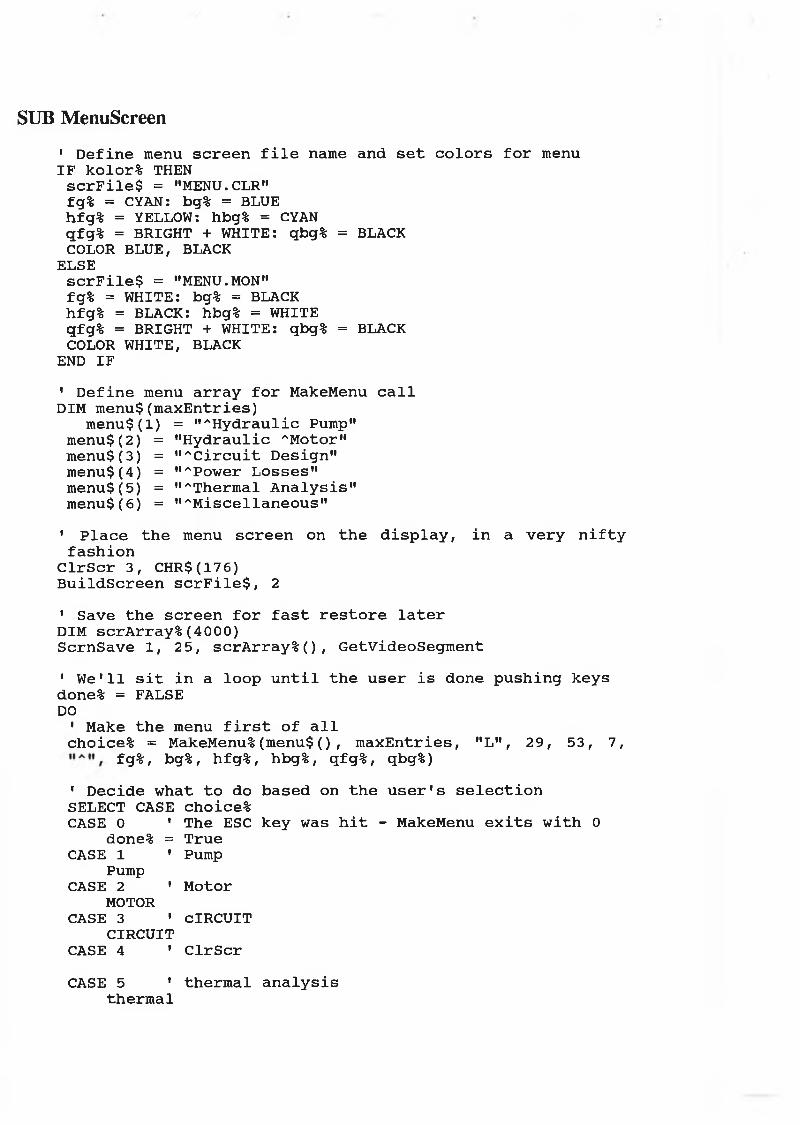
SUB MenuScreen
• D e f in e menu s c r e e n f i l e name and s e t c o l o r s f o r menu IF kolor% THEN
s c r F i l e $ = "MENU.CLR" fg% = CYAN: bg% = BLUE hfg% = YELLOW: hbg% = CYAN qfg% = BRIGHT + WHITE: qbg% = BLACK COLOR BLUE, BLACK
ELSEs c r F i l e $ = "MENU.MON" fg% = WHITE: bg% = BLACK hfg% = BLACK: hbg% = WHITE qfg% = BRIGHT + WHITE: qbg% = BLACK COLOR WHITE, BLACK
END IF
1 D e f in e menu a r r a y f o r MakeMenu c a l l DIM m en u $(m axE n tries)
m en u $ (l) = " ''H yd rau lic Pump" m enu$(2) = " H y d ra u lic ^Motor" m enu$(3) = " ^ C ir c u i t D esign " m enu$(4) = "APower L o sse s" m enu$(5) = "''Thermal A n a ly s i s " m enu$(6) = " ' 'M isc e l la n e o u s"
' P la c e t h e menu s c r e e n on t h e d i s p l a y , i n a v e r y n i f t y f a s h i o n
C lr S c r 3 , CHR$(17 6)B u i ld S c r e e n s c r F i l e $ , 2
1 Save t h e s c r e e n f o r f a s t r e s t o r e l a t e r DIM s c r A r r a y %(4000)S crn S a v e 1 , 2 5 , scrA rra y % (), G etV ideoSegm ent
1 W e ' l l s i t in a lo o p u n t i l t h e u s e r i s done p u s h in g k e y s done% = FALSE DO
' Make t h e menu f i r s t o f a l lchoice% = MakeMenu%(menu$( ) , m a x E n tr ie s , "L", 2 9 , 5 3 , 7 ,
fg%, bg%, hfg%, hbg%, qfg%, qbg%)
1 D e c id e w hat t o do b a se d on t h e u s e r 1s s e l e c t i o nSELECT CASE choice%CASE 0 ' The ESC k e y was h i t - MakeMenu e x i t s w i t h 0
done% = TrueCASE 1 ' Pump
PumpCASE 2 ' Motor
MOTORCASE 3 ' CIRCUIT
CIRCUITCASE 4 1 C lr S c r
CASE 5 1 th e r m a l a n a l y s i sth e r m a l

CASE ELSE END SELECT
' R e s t o r e t h e s c r e e n a f t e r s e l e c t e d demo r e t u r n s IF NOT (done%) THEN
S c r n R e s to r e 1 , 2 5 , scrA rra y % (), G etV ideoSegm ent END IF
LOOP UNTIL done%
END SUB

SUB MovingMessage
1 A few l o c a l v a r s b ig P a u s e = 750 l i t t l e P a u s e = 35
' S e tu p our s c r n s a v e a r r a y sDIM under% (B lockSize% (3 4 , 4 6 , 1 9 , 1 9 ) )DIM over% (B lock S ize% (3 4 , 4 6 , 19 , 1 9 ) ) segm en t = G etV ideoSegm ent
1 S e t c o l o r s IF kolor% THEN
COLOR 1 5 , 4 ELSE
COLOR 0 , 7 END IF
1 Save p o r t i o n o f s c r e e n and make t h e i n i t i a l m essa g e B lo c k S a v e 3 4 , 4 6 , 1 9 , 1 9 , under% (), segm en t LOCATE 1 9 , 3 4 , 0: PRINT " H it any k e y ";B lo c k S a v e 3 4 , 4 6 , 1 9 , 1 9 , over%( ) , segm en t IF Pau se% (b igP au se) = FALSE THEN
EXIT SUB END IF
1 Move m essa g e t o l e f t s i d e o f s c r e e n FOR x% = 34 TO 6 STEP -2
B lo c k R e s to r e x%, x% + 12 , 1 9 , 1 9 , o v e r % (), segm en t IF P a u s e % ( l i t t l e P a u s e ) = FALSE THEN
EXIT SUB END IFB lo c k R e s t o r e x%, x% + 1 2 , 1 9 , 1 9 , under%( ) , segm en t
NEXT x%B lo c k R e s t o r e x%, x% + 1 2 , 19 , 19 , over% ( ) , segm en t IF P au se% (b igP au se) = FALSE THEN
EXIT SUB END IF
' S i t i n a lo o p t h a t m oves t h e m e ssa g e w h i l e w a i t i n g f o r a k e y p r e s s
done% = FALSE DO
1 Move upFOR y% = 18 TO 4 STEP - 1
B lo c k R e s t o r e 4 , 1 6 , y% + 1 , y% + 1 , under% (), segm en t B lo c k S a v e 4 , 16 , y%, y%, under% (), segm en t B lo c k R e s t o r e 4 , 1 6 , y%, y%, o v er% () , segm ent IF Pause%( l i t t l e P a u s e ) = FALSE THEN
EXIT SUB END IF
NEXT y%IF P au se% (b igP au se) = FALSE THEN
EXIT SUB END IF

'Move r i g h tFOR x% = 4 TO 64 STEP 2
B lo c k R e s to r e x%, x% + 12 , 4 , 4 , o v e r % (), segm en t IF P a u s e % ( l i t t l e P a u s e ) = FALSE THEN
EXIT SUB END IFB lo c k R e s t o r e x%, x% + 1 2 , 4 , 4 , under%( ) , segm en t
NEXT x%B lo c k R e s t o r e x%, x% + 1 2 , 4 , 4 , o v er% (), segm en t IF P au se% (b igP au se) = FALSE THEN
EXIT SUB END IF
1 Move down FOR y% = 5 TO 19
B lo c k R e s t o r e 6 6 , 7 8 , y% - 1 , y% - 1 , u n d e r %(), segm ent B lo c k S a v e 6 6 , 7 8 , y%, y%, under%( ) , segm en t B lo c k R e s to r e 66 , 7 8 , y%, y%, o v er% () , segm ent IF P a u s e % ( l i t t l e P a u s e ) = FALSE THEN
EXIT SUB END IF
NEXT y%IF P au se% (b igP au se) = FALSE THEN
EXIT SUB END IF
» Move l e f tFOR x% = 66 TO 6 STEP -2
B lo c k R e s t o r e x%, x% + 12 , 19 , 1 9 , over% ( ) , segm en t IF P a u s e % ( l i t t l e P a u s e ) = FALSE THEN
EXIT SUB END IFB lo c k R e s t o r e x%, x% + 12 , 1 9 , 1 9 , under%( ) , segm ent
NEXT x%B lo c k R e s to r e x%, x% + 1 2 , 19 , 1 9 , over% ( ) , segm en t IF P au se% (b igP au se) = FALSE THEN
EXIT SUB END IF
LOOP UNTIL done%
END SUB
SUB YESORNO' ****************SUBR0UTINE FOR YES/NOCHECK*******************
WHILE ANS$ <> "YES” AND ANS$ <> "yes" AND ANS$ <> "NO" AND ANS$ <> "no"CLS : LOCATE 15 , 15: INPUT "THAT'S A 'YES' o r 'NO' I'M LOOKING FOR ANS$WEND
END SUB

SUB thermal
C lr S c r 5 , 11 "MakeWindow 8 , 1 2 , 1 1 , 68 , 1 4 , 1 , 0 , 2 , 1 6 , 1 , "Open a F i l e " LOCATE 9 , 15: INPUT "What f i l e name w ould you l i k e t o open";F ilen a m e$OPEN F ile n a m e $ FOR OUTPUT AS #1 OPTION BASE 1PRINT # 1 , "GENERAL CHART"DIM Q 1( 6 0 ) , Q2( 6 0 ) , Q 3 (7 0 ) , HAV(60), H A P(60), H A P1(60), T w v (6 0 ) , Twp( 6 0 ) , D T f( 6 0 ) , T f (60)DIM HA( 7 0 ) , H I ( 6 0 ) , H 2 (6 0 ) , G R (60), T l ( 6 0 ) , T 2 ( 6 0 ) , D T 2 (6 0 ) ,AA( 6 0 ) , DTFR( 6 0 ) , TFR(60) i = 1C lr S c r 6 , " "MakeWindow 1 0 , 6 , 1 5 , 7 5 , 1 4 , 1 , 0 , 3 , 1 6 , 1 , " In p u t Data f o rP ip e s "LOCATE 1 2 , 15: INPUT "E nter t h e a tm o s p h e r ic t e m p e r a tu r e , Ta in K"; TaC lr S c r 1 2 , " "MakeWindow 1 0 , 6 , 1 5 , 7 5 , 1 4 , 1 , 0 , 5 , 1 6 , 2 , " In p u t Data f o rP ip e s "LOCATE 1 2 , 15: INPUT "E nter t h e k i n i m a t i c v i s c o s i t y MU inmA2 / s e c . " ; MU C lr S c r 3 , " "MakeWindow 1 0 , 6 , 1 5 , 7 5 , 1 4 , 5 , 0 , 2 , 16 , 2 , " In p u t D ata f o rP ip e s "LOCATE 1 2 , 15: INPUT "E nter t h e i n i t i a l f l u i d t e m p e r a tu r e T f (0 ) in K"; T f ( i )C lr S c r 4 , " "MakeWindow 10 , 6 , 1 5 , 7 8 , 1 0 , 4 , 0 , 5 , 1 6 , 2 , " In p u t Data f o rP i p e s "LOCATE 1 2 , 12: INPUT "E nter t h e t e m p e r a tu r e o f o u t s i d e w a l l o f t h e p i p e T 2 (0) i n K"; T 2 ( i )C lr S c r 8 , " "MakeWindow 1 0 , 6 , 1 5 , 7 7 , 1 3 , 1, 0 , 5 , 1 6 , 1 , " In p u t D ata f o rP ip e s "LOCATE 1 2 , 12: INPUT "E nter t h e i n s i d e d ia m e te r o f p ip e , d l in [m ]"; d l C lr S c r 9 , " "MakeWindow 10 , 6 , 1 5 , 7 5 , 1 3 , 1 4 , 0 , 6 , 1 6 , 1 , " In p u t D ata f o rP ip e s "LOCATE 12 , 15: INPUT "E nter t h e o u t s i d e d ia m e te r o f p i p e , d2 in [m ]" ; d2 C lr S c r 1 0 , " "MakeWindow 1 0 , 6 , 15 , 7 5 , 1 6 , 6 , 0 , 5 , 1 6 , 1 , " In p u t D ata f o rP ip e s "LOCATE 1 2 , 15: INPUT "E nter t h e l e n g t h o f p i p e , L i n [m]"; L C lr S c r 1, " "MakeWindow 1 0 , 6 , 15 , 7 5 , 1 4 , 1, 0 , 2 , 1 6 , 2 , " In p u t D ata f o rP ip e"LOCATE 1 2 , 15: INPUT "E n ter t h e d e n s i t y o f p ip e m a t e r i a l Rp in kg/m ~3"; Rp C lr S c r 2 , " "MakeWindow 10 , 6 , 1 5 , 7 5 , 1 4 , 1 , 0 , 2 , 1 6 , 1 , " In p u t D ata f o rF lu id "LOCATE 1 2 , 15: INPUT " E n ter t h e d e n s i t y o f f l u i d Rf i n kg/m A3";

RfC lr S c r 3 , " "MakeWindow 1 0 , 6 , 1 5 , 7 5 , 1 4 , 4 , 0 , 5 , 1 6 , 1 , " In p u t D ata f o rF lu id "LOCATE 1 2 , 15: INPUT "E nter f lo w r a t e o f f l u i d Qf i n mA3 / s " ; Qf C lr S c r 4 , " "MakeWindow 1 0 , 6 , 1 5 , 7 7 , 1 0 , 4 , 0 , 5 , 1 6 , 1 , " In p u t Data f o rP ip e s "INPUT "E nter t h e volum e o f f l u i d Vf in mA3"; VfLOCATE 1 2 , 12: INPUT "E nter t h e th e r m a l c o n d u c t i v i t y ,k o f p ip e w a l l m a t e r i a l "; K C lr S c r 5 , " "MakeWindow 1 0 , 6 , 15 , 7 5 , 7 , 1 , 0 , 6 , 1 6 , 2 , " In p u t D ata f o rP ip e s "LOCATE 1 2 , 15: INPUT "E nter t h e e m i s s i v i t y o f p i p e w a l l m a t e r i a l E EC lr S c r 6 , " "MakeWindow 1 0 , 6 , 1 5 , 7 5 , 1 4 , 4 , 0 , 2 , 1 6 , 1 , " In p u t D ata f o rF lu id "LOCATE 1 2 , 15: INPUT "E nter f l u i d s p e c i f i c h e a t C pf"; Cpf C lr S c r 7 , " "MakeWindow 1 0 , 6 , 1 5 , 7 5 , 1 5 , 1 , 0 , 2 , 1 6 , 1 , " In p u t Data f o rP ip e s"LOCATE 1 2 , 15: INPUT "E nter p ip e w a l l s p e c i f i c h e a t Cpp"; Cpp C lr S c r 8 , " "MakeWindow 1 0 , 6 , 15 , 7 5 , 1 4 , 4 , 0 , 5 , 1 6 , 2 , " In p u t D ata f o rPower L o s se s"LOCATE 1 2 , 15: INPUT "E nter t o t a l power l o s s e s W in W atts" ; W C lr S c r 9 , " "MakeWindow 1 0 , 6 , 15 , 7 5 , 1 5 , 1 , 0 , 6 , 16 , 2 , " In p u t Data" LOCATE 1 2 , 15: INPUT "E nter i n i t i a l o u t s i d e v e r t i c a l ta n kte m p e r a tu r e in °K Twv"; T w v(i)C lr S c r 1 0 , " "MakeWindow 1 0 , 6 , 1 5 , 7 9 , 1 5 , 1 , 0 , 6 , 16 , 2 , " In p u t Data"LOCATE 1 2 , 15 : INPUT "E nter i n i t i a l ta n k b ottom w a l l t e m p e r a tu r ein °K, Twp "; Tw p(i)C lr S c r 1 1 , " "MakeWindow 1 0 , 6 , 1 5 , 7 9 , 1 4 , 4 , 0 , 6 , 1 6 , 2 , " In p u t Data "LOCATE 1 2 , 15: INPUT "E nter t h i c k n e s s o f ta n k w a l l in [m ], x" ;xC lr S c r 1 2 , " "MakeWindow 1 0 , 6 , 1 5 , 7 9 , 1 4 , 4 , 0 , 6 , 1 6 , 2 , " In p u t Data f o r t h e R e s e r v o ir "LOCATE 1 2 , 15: INPUT "E nter d e n s i t y o f ta n k w a l l m a t e r i a l Rt in [k g /m " 3 ]" ; Rt C lr S c r 1 3 , " "MakeWindow 1 0 , 6 , 15 , 7 9 , 1 4 , 4 , 0 , 6, 1 6 , 2 , " In p u t Data f o r t h e R e s e r v o ir "LOCATE 12 , 15: INPUT "E nter h t , f l u i d h e i g h t i n [m]"; h t C lr S c r 14 , " "MakeWindow 1 0 , 6 , 15 , 8 0 , 1 4 , 1 , 0 , 6 , 16 , 2 , " In p u t Data f o r t h e R e s e r v o ir "LOCATE 1 2 , 10: INPUT "E nter T t , t e m p e r a tu r e o f a i r i n s i d e t h er e s e r v o i r ab ove t h e f l u i d s u r f a c e i n °k"; Tt C lr S c r 1 , " "MakeWindow 1 0 , 6 , 15 , 7 5 , 1 4 , 1 , 0 , 6 , 1 6 , 2 , " In p u t Data f o r t h e R e s e r v o ir "LOCATE 1 2 , 15: INPUT " E n ter L I , l e n g t h o f ta n k i n [m]"; LI

C lr S c r 2 , " "MakeWindow 1 0 , 6 , 15 , 7 5 , 14 , 1 , 0 , 6 , 1 6 , 2 , " In p u t D ata f o r t h e R e s e r v o ir "LOCATE 1 2 , 15: INPUT "E nter S, w id th o f ta n k in [m] " ; S C lr S c r 3 , " "MakeWindow 1 0 , 6 , 1 5 , 7 9 , 1 4 , 1 , 0 , 2 , 1 6 , 2 , " In p u t D ata f o r t h e R e s e r v o ir "LOCATE 1 2 , 15: INPUT "E nter th e r m a l c o n d u c t i v i t y , k l o f ta n k w a l l m a t e r i a l " ; k l C lr S c r 4 , " "MakeWindow 1 0 , 6 , 15 , 7 9 , 1 4 , 1 , 0 , 2 , 1 6 , 2 , " In p u t D ata f o r t h e R e s e r v o ir "LOCATE 1 2 , 15: INPUT "E nter s p e c i f i c h e a t Cpt o f ta n k w a l lm a t e r i a l " ; Cpt C lr S c r 5 , " "MakeWindow 1 0 , 6 , 15 , 7 5 , 1 4 , 4 , 0 , 2 , 1 6 , 2 , " In p u t D ata f o r t h e R e s e r v o ir "LOCATE 1 2 , 15: INPUT "E nter W1 i n W atts "; W1 C lr S c r 6 , " 11FMT1$ = » ## # # # .# # # # # .# # # # # •# # .# # # # # # # # # -# #
. ## ••PRINT # 1 , " i T l ( i ) H I ( i ) H 2 ( i) D T 2 ( i+ l) T 2 ( i+ 1 )T fR ( i+ 1 ) "A l l = ( 3 .1 4 * d l A 2) / 4A21 = ( 3 .1 4 * d2 A 2) / 4A l = 3 .1 4 * d l * LA2 = 3 .1 4 * d2 * LSEQ = 5 .6 7 E -0 8VF = (S * LI * h t ) * 1000HF = ( 3 .6 5 * K) / d lG = 9 .8 1 0 0 0 1MF = (Rf * Qf) / 60AA61 = S * LIAA62 = h t * LIAA63 = h t * SVP = (A21 * L)MF1 = Rf * VF MP = Rp * VPBIT = 1 / TaFOR DT = 60 TO 3 000 STEP 25HA( i ) = 1 .3 2 * ( (T 2 ( i ) - Ta) / d2) A .2 5H 2 ( i ) = (HA( i ) * A2 * ( T 2 ( i ) - T a ) ) + (E * SEQ * A2 * ( T 2 ( i ) A4 - Ta A 4 ) )R1 = d l / 2R2 = d2 / 2AM = (A2 - A l) / (LOG(R2 / R l ) )AA( i ) = HF * A l * T f ( i )B = (K * AM) / (R2 - R l)C = HF * AlT l ( i ) = (AA( i ) + (B * T 2 ( i ) ) ) / (C + B)H I ( i ) = HF * A l * ( T f ( i ) - T 1 ( i ) )DT2( i + 1) = (H I( i ) - H 2( i ) ) / (MP * Cpp)IF DT2( I + 1) = 0 THEN ENDT 2 ( i + 1) = T 2 ( i ) + DT2( i + 1 ) * DTDTf1 ( i + 1) = (W - H I ( i ) ) / (M fl * Cpf)T f 1 ( i + 1) = T f ( i ) + DTf1 ( i + 1 ) * Dt HAV(i) = 1 .4 2 * ( (T w v ( i ) - Ta) / LI) A .25Q l ( i ) = 2 * HAV(i) * (AA62 + AA63) * (T w v(i) - Ta) + (E * SEQ *

(A2 + A3) * (T w v(i) A 4 - Ta A 4 ) )HAP(i) = 1 .4 2 * { (T w p (i) - Ta) / LI) A .25 H A P l(i) = 1 .4 2 * ( (T w p (i) - Tt) / LI) * .25Q 2 ( i ) = HAP(i) * AA61 * (Tw p(i) - Ta) + (E * SEQ * A1 * (Tw rp(i) A 4 - Ta A 4 ) )Q 3 ( i ) = H A P l( i) * AA61 * ( T f ( i ) - Tt) + (E * SEQ * A1 * (Tw rp(i) - 4 - Ta A 4))DTFR( i + 1) = (W1 - Q l ( i ) - Q 2 ( i) - Q 3 ( i ) ) / (MF1 * Cpf)TFR(i + 1) = T f ( i ) + DTFR( i + 1 ) * DTDTf(i +1) = ((W - HI(i)) + (MF * Cpf * ((TFR(i + 1) - Tf(i)))))/ (MF1 * Cpf)IF DTf(i + 1) < 0 THEN GOTO 930222 Tf(i + 1) = Tf(i) + (DTf(i + 1) * DT)PRINT USING FMT1$; i; Tl(i) ; Hl(i) ; H2(i) ; DT2 (i + 1) ; T2(i + 1) ;TFR (i + 1)PRINT #1, USING FMT1$; i; Tl(i); Hl(i); H2(i); DT2(i + 1); T2(i + 1); TFR(i + 1) i = i + 1Twp(i) = ((HAP(i - 1) * Ta) + ((kl / x) * Tf(i))) / (HAP(i - 1) + ( k l / x ) )T w v(i) = ( ( HAV( i - 1) * Ta) + ( ( k l / x) * T f ( i ) ) ) / (HAV( i - 1) + ( k l / x ) )NEXT DTFMT2 $ = " ## # # # .# # # # .# # # # # .# # # # .# # # # •# # .# # # # #
# # # . ##»»PRINT # 1 , " i Twv Q1 Twp Q2 Q3D T f( i+ 1 ) T f ( i + 1 ) "FOR i = 1 TO 60 PRINTPRINT " * * * * * * * * * * * * * * * * * * * * * * * * * * * * * * * * * * * * * * * * * * * * * * * * * * * * * * " RINT USING FMT2$; i ; T w v ( i ) ; Q l ( i ) ; T w p ( i) ; Q 2 ( i ) ; Q 3 ( i ) ; D T f( i + 1) ; Tf ( i + 1)PRINT # 1 , USING FMT2$; i ; T w v ( i ) ; Q l ( i ) ; T w p ( i ) ; Q 2 ( i ) ; Q 3 ( i ) ; D T f( i + 1 ) ; T f ( i + 1)IF D T f( i + 1) < 0 THEN END NEXT i CLOSE #1P ressK ey$ = INPUT$(1)MakeWindow 2 0 , 6 , 1 2 , 7 0 , 1 4 , 4 , 0 , 2 , 1 6 , 2 , "Save t h e R e s u l t s " C e n te r " The R e s u l t s Have b een Save in f i l l e G e n e r a l .d a t " , 20 P ressK ey$ = INPUT$(1)C lr S c r 1 5 , " "ENDEND SUB

SUB CIRCUIT
DIM H( 1 5 ) , N .0 F R E $ (1 5 ) , D P (1 5 ) , H H (15), HG(15)C lr S c r 3 , " "MakeWindow 1 0 , 5 , 1 5 , 70 , 1 4 , 1 , 0 , 1 , 16 , 2 , ""LOCATE 1 2 , 10INPUT "DO YOU HAVE MORE THAN ONE DIAMETER ANS$
YESORNO 'YES OR NO CHECKWHILE ANS$ = "YES" OR ANS$ = "yes"C lr S c r 3 , " "MakeWindow 1 0 , 8 , 15 , 7 7 , 17 , 6 , 0 , 1 , 16 , 1 , " I n p u t D ata f o r P ip e s "LOCATE 1 2 , 10: INPUT "WHAT IS THE DIAMETER OF THE PIPE OF THESYSTEM"; d WHILE d < 0MakeWindow 1 8 , 9 , 2 2 , 5 5 , 1 4 , 4 , 0 , 1 , 16 , 1 , "Warning"LOCATE 2 0 , 10: INPUT "THAT MUST BE A NUMBER > 0 "; dWENDMakeWindow 4 , 6 , 1 1 , 7 5 , 1 4 , 1 , 0 , 1 , 16 , 2 , " In p u t D ata f o r a Pump"LOCATE 7 , 10: INPUT "E nter t h e d i s p la c e m e n t o f a pump [CmA3 / r e v . ]" ; VP C lr S c r 3 , " "MakeWindow 4 , 6 , 1 1 , 75 , 1 5 , 1 , 3 , 1 , 1 6 , 3 , " In p u t D ata f o r t h e Pump"LOCATE 7 , 10: INPUT "E nter t h e Speed o f t h e Pump [ r .p .m ] "; NP C lr S c r 1 5 , " "MakeWindow 6 , 6 , 1 1 , 75 , 1 4 , 3 , 0 , 3 , 16 , 1 , " In p u t D ata f o r t h e Pump"LOCATE 8 , 10: INPUT " E n ter t h e v o lu m e t r i c e f f i c i e n c y o f t h epump"; PVEQPA = (PVE * VP * .0 0 1 ) * NP 590 a = ( 3 .1 4 * (d A 2 ) ) / 4 C lr S c r 1 5 , " "MakeWindow 1 3 , 6 , 18 , 7 7 , 1 4 , 1 , 2 , 3 , 16 , 1 , " R esu lt"LOCATE 1 5 , 15: PRINT "The a r e a o f ("; d; " m) p i p e A= "; a;" [mA2 ] "V = (10 A -3 * QPA) / (60 * a)LOCATE 1 6 , 15: PRINT "The s p e e d o f t h e f lo w in ("; d; " m) V=";V; " [ m / s e c . ] "MakeWindow 2 0 , 6 , 2 3 , 7 0 , 1 4 , 4 , 0 , 3 , 1 6 , 1 , " In p u t Data f o rF lu id "LOCATE 21 , 15: INPUT "what i s k e n im a t ic v i s c o c i t y MU [mA2 / s e c ] " ; MUC lr S c r 1 2 , " "RN = (V * d) / MUMakeWindow 6 , 6 , 14 , 7 0 , 1 4 , 1 , 0 , 3 , 1 6 , 1 , " R e s u l t"LOCATE 8 , 8: PRINT "R eyn old s Number Rn= "; RN
IF RN <= 2000 THENMakeWindow 1 1 , 3 0 , 14 , 5 5 , 14 , 4 , 0 , 1 , 0 , 1, ""LOCATE 1 2 , 31: PRINT "T h is Flow i s Laminar" f = 64 / RNC e n te r " P r e s s Any Key t o C o n t in u e ", 2 0 P ressK ey $ = INPUT$(1)C lr S c r 3 , " "MakeWindow 1 2 , 6 , 1 6 , 7 5 , 1 5 , 2 , 2 , 3 , 16 , 1 , " R e s u l t"

LOCATE 1 4 , 10: PRINT "The f r i c t i o n f a c t o r f f o r la m in a r f lo w i sf ="; fELSETURBULANT END IFMakeWindow 12 , 6 , 1 6 , 7 5 , 1 4 , 4 , 0 , 3 , 1 6 , 1 , " In p u t D ata " LOCATE 1 4 , 10: INPUT "E nter t h e v a l u e o f g [ m /s e c A2] "; GMakeWindow 1 8 , 6 , 2 2 , 7 7 , 1 4 , 1 , 0 , 3 , 1 6 , 2 , " In p u t D ata f o r th eP ip e s"LOCATE 2 0 , 6: PRINT " what i s t h e t o t a l l e n g t h o f t h e d ia m e te r ("; d; ") ";INPUT LLHLL = f * (LL / d) * (V A 2 / 2 * G)LOCATE 8 , 12: PRINT "HLL="; HLL; " [m ]"C lr S c r 1 5 , " "MakeWindow 6 , 6 , 9 , 7 5 , 1 5 , 6 , 0 , 3 , 1 6 , 1 , " In p u t D ata " LOCATE 8 , 8 : INPUT "How many r e s t r i c t o r a r e t h e r e " ; TOT WHILE TOT <= 0 OR TOT > 15MakeWindow 18 , 6 , 2 2 , 60 , 1 4 , 4 , 0 , 3 , 16 , 1 , "Warning"LOCATE 2 0 , 8: INPUT "Sorry m ust b e > 0 and < 15"; TOTWENDC lr S c r 8 , " "H (0) = 0MakeWindow 6 , 6 , 1 2 , 7 7 , 1 4 , 1 , 0 , 3 , 16 , 1 , " In p u t Data "LOCATE 8 , 10: INPUT "E nter t h e v a l u e o f s p e c i f i c g r a v i t y o fh y d r a u l i c o i l S g " ; SG C lr S c r 1 , " "FOR L = 1 TO TOTMakeWindow 6 , 6 , 1 6 , 7 7 , 1 7 , 6 , 0 , 3 , 1 6 , 1 , " I n p u t D ata " LOCATE 8 , 10: PRINT "E nter t h e name o f r e s t r i c t o r ("; L; ")" LOCATE 10 , 10: INPUT N.OFRE$(L)MakeWindow 1 2 , 12 , 16 , 7 0 , 14 , 1 , 0 , 1 , 16 , 1 , ""LOCATE 1 2 , 15: PRINT "What i s t h e v a l u e o f p r e s s u r e d r o p (" ; L;") [N/mA2 ]" ;INPUT DP(L)H(L) = (10 * D P (L )) / SG: HH(L) = H(L)H(L) = H(L - 1) + H(L)HG(L) = DP(L) * QPA OMFR = QPA * SG * 1 OSH = 1 . 7 5T I (1) = HG(1) / OSH * OMFR NEXT LC lr S c r 1 3 , " "MakeWindow 6 , 6 , 1 5 , 77 , 1 4 , 1 , 0 , 3 , 16 , 1 , " R e su lt s"LOCATE 7 , 7FMT1$ = " ## \ \ # # # # # .# # # # # # # # .# # # # # # # .# ## # # # # # .# # ••PRINT " L Name DP [b a r] Head lo s s [ m ] HH [m]H e a t . G [K J/m in] "FOR L = 1 TO TOTPRINT USING FMT1$; TAB( 8 ) ; L; N.OFRE$(L); DP(L); H (L ); HH(L); HG (L)IF L = TOT THEN PRINT H (L ): HTOT = H(L)NEXT LLOCATE 2 4 , 15: PRINT " P r e s s any k ey t o c o n t in u e : " ;INPUT a$C lr S c r 1 5 , " "MakeWindow 6 , 6 , 1 6 , 7 5 , 1 4 , 1 , 0 , 1 , 16 , 1 , " I n p u t Data "

L O C A T E 8 , 1 0 : I N P U T "H o w m a n y s t a n d a r d 9 0 e lb o w i s t h e r e " ; E L I M a k e W in d o w 1 3 , 8 , 1 6 , 6 0 , 1 5 , 4 , 0 , 1 , 1 6 , 1 , " I n p u t D a t a "H E 1 = E L I * ( . 9 ) * ( V A 2 ) / ( 2 * G )L O C A T E 1 4 , 1 0 : I N P U T "H o w m a n y s t a n d a r d 4 5 e lb o w i s t h e r e E L 2 " ; E L 2C l r S c r 1 0 , " "H E 2 = E L 2 * ( . 4 2 ) * ( V A 2 / 2 * G )M a k e W in d o w 1 2 , 6 , 1 7 , 7 7 , 1 4 , 3 , 0 , 3 , 1 6 , 1 , " R e s u l t "L O C A T E 1 5 , 1 0 : P R I N T " H E 1 = " ; H E 1 ; " [ m ] " ; " H E 2 = " ; H E 2 ; " [ m ] » H T O T A L = H L L + H E 1 + H E 2 + H T O T L O C A T E 2 2 , 1 0P R I N T " P r e s s A n y K e y t o C o n t i n u e "P r e s s K e y $ = I N P U T $ ( 1 )C l r S c r 1 , " "M a k e W in d o w 6 , 6 , 1 6 , 7 7 , 1 5 , 1 , 0 , 3 , 1 6 , 1 , " R e s u l t s "L O C A T E 7 , 7P R I N T " T h e t o t a l h e a d l o s s i n ( " ; d ; " m) d i a m e t e r o f t h e p i p e = " ; H T O T A L ; " [ m ] "D P = ( S G * H T O T A L )L O C A T E 1 9 , 1 0M a k e W in d o w 1 0 , 6 , 1 6 , 7 7 , 1 4 , 4 , 0 , 2 , 1 6 , 2 , " "L O C A T E 1 1 , 9P R I N T " T o t a l p r e s s u r e d r o p i n ( " ; d ; "m ) d i a m e t e r o f t h e p i p e d P = " ; D P ; " [ b a r ] "L O C A T E 2 3 , 1 0P R I N T " P r e s s A n y K e y t o C o n t i n u e "P r e s s K e y $ = I N P U T $ ( 1 )C l r S c r 1 4 , " "M a k e W in d o w 6 , 6 , 1 0 , 7 7 , 1 4 , 1 , 0 , 1 , 1 6 , 1 , " "L O C A T E 7 , 8IN P U T "D O YO U W ANT T O GO ON F O R N E X T D IA M E T E R " ; A N S $Y E S O R N O ' Y E S O R NO C H E C K 'WEND E N D S U B

SUB MOTOR
C l r S c r 2 , " "M a k e W in d o w 8 , 1 0 , 1 3 , 7 5 , 1 5 , 1 , 0 , 2 , 1 6 , 2 , " I n p u t D a t a f o r t h e M o t o r "L O C A T E 1 0 , 1 4 : I N P U T " E n t e r t h e d i s p l a c e m e n t o f t h e h y d r a u l i cm o t o r V m " ; VM C l r S c r 3 , " "M a k e W in d o w 8 , 1 0 , 1 3 , 7 5 , 1 5 , 1 , 0 , 2 , 1 6 , 2 , " I n p u t D a t a f o r t h e P u m p "L O C A T E 1 0 , 1 4 : I N P U T " E n t e r t h e d i s p l a c e m e n t o f t h e h y d r a u l i cp u m p V p " ; V P C l r S c r 3 , " "M a k e W in d o w 8 , 1 0 , 1 3 , 7 5 , 1 5 , 1 , 0 , 3 , 1 6 , 2 , " I n p u t D a t a f o r t h e P u m p "L O C A T E 1 0 , 1 4 : I N P U T " E n t e r t h e s p e e d o f t h e p u m p [ r p m ] " ; N P 3 8 0 NM = N P * V P / VM C l r S c r 4 , " "M a k e W in d o w 8 , 1 0 , 1 3 , 7 0 , 4 , 7 , 0 , 3 , 1 6 , 2 , " I n p u t D a t a f o r t h e P r e s s u r e "L O C A T E 1 0 , 1 3 : I N P U T " E n t e r t h e o p e r a t i n g p r e s s u r e P [ b a r ] " ; P C l r S c r 4 , " "M a k e W in d o w 8 , 1 0 , 1 4 , 7 5 , 1 5 , 4 , 0 , 4 , 1 6 , 2 , " R e s u l t s "L O C A T E 1 0 , 1 3 : P R I N T " T h e s p e e d o f t h e h y d r a u l i c m o t o r i s Nm = " ; N M ; " [ r p m ] "QMT = NM * VM * . 0 0 1L O C A T E 1 1 , 1 3 : P R I N T " T h e o r e t i c a l f l o w r a t e o f t h e m o t o r i s Q m t = " ; Q M T; " [ L / M I N ] "C e n t e r " P r e s s A n y K e y t o C o n t i n u e " , 2 0 P r e s s K e y $ = I N P U T $ ( 1 )C l r S c r 4 , " "M a k e W in d o w 8 , 1 0 , 1 2 , 7 5 , 1 4 , 1 , 0 , 3 , 1 6 , 2 , " I n p u t D a t a f o r t h e M o t o r "L O C A T E 1 0 , 1 2 : I N P U T " E n t e r t h e v o l u m e t r i c e f f i c i e n c y o f f l u i dp o w e r m o t p r m V E " ; M VEQMA = (VM * . 0 0 1 * NM) / M VEM a k e W in d o w 6 , 8 , 1 2 , 7 5 , 1 4 , 1 , 0 , 3 , 1 6 , 2 , " R e s u l t s "L O C A T E 8 , 1 0 : P R I N T " A c t u a l f l o w r a t e o f t h e h y d r a u l i c m o t o r i s Q m a= " ; QM A; " [ L / m i n ] "TM = (VM * . 0 0 0 0 0 1 ) * ( P * 1 0 0 0 0 0 ! ) / ( 2 * 3 . 1 4 )L O C A T E 9 , 1 0 : P R I N T " T h e o r e t i c a l o u t p u t t o r q u e o f t h e m o t o r i s T m = " ; T M ; " [ N . m ] "FH P M = QMA * P / 6 0 0L O C A T E 1 0 , 1 0 : P R I N T " A c t u a l o u t p u t p o w e r o f t h e m o t o r i s F h p m = " ; F H P M ; " [ K W ] "C e n t e r " P r e s s A n y K e y t o C o n t i n u e " , 2 0 P r e s s K e y $ = I N P U T $ ( 1 )E N D S U B

C l r S c r 5 , " 11M a k e W in d o w 8 , 1 2 , 1 1 , 6 0 , 1 4 , 1 , 0 , 2 , 1 6 , 1 , " O p e n a F i l e " L O C A T E 9 , 1 5 : I N P U T " W h a t f i l e n a m e w o u ld y o u l i k e t o o p e n " ;F i l e n a m e $O P E N F i l e n a m e $ F O R O U T P U T A S # 1 C l r S c r 6 , " "M a k e W in d o w 4 , 6 , 9 , 7 0 , 1 4 , 1 , 0 , 1 , 1 6 , 2 , " I n p u t D a t a f o r P u m p " 1 6 0 L O C A T E 7 , 1 0 : IN P U T " E n t e r t h e d i s p l a c e m e n t o f t h e p u m p[ c m A 3 / r e v ] " ; V P C l r S c r 1 5 , " »M a k e W in d o w 4 , 6 , 9 , 7 0 , 1 5 , 3 , 0 , 1 , 1 6 , 2 , " I n p u t D a t a f o rP u m p "L O C A T E 7 , 1 0 : I N P U T " E n t e r t h e o p e r a t i n g p r e s s u r e P [ b a r ] " ; P C l r S c r 3 , " "M a k e W in d o w 4 , 6 , 1 1 , 7 5 , 1 5 , 1 , 3 , 1 , 1 6 , 3 , " I n p u t D a t a f o rP u m p "L O C A T E 7 , 1 0 : I N P U T " E n t e r t h e s p e e d o f t h e p u m p N p [ r p m ] " ; N P Q P T = ( V P * N P ) * . 0 0 1 C l r S c r 1 5 , " "M a k e W in d o w 6 , 6 , 1 1 , 7 0 , 1 4 , 3 , 0 , 3 , 1 6 , 1 , " I n p u t D a t a f o rP u m p "L O C A T E 9 , 1 0 : I N P U T " E n t e r t h e v o l u m e t r i c e f f i c i e n c y o f t h e p u m p p V E " ; P V EQ P A = ( P V E * V P * . 0 0 1 ) * N P F H P P = (Q P A * P ) / 6 0 0M a k e W in d o w 5 , 6 , 1 1 , 7 5 , 1 4 , 4 , 0 , 5 , 1 6 , 1 , " R e s u l t s "L O C A T E 7 , 1 0 : P R I N T " T h e o r e t i c a l f l o w r a t e o f t h e p u m p Q p t = " ;Q P T ; " [ L / m i n ] "L O C A T E 8 , 1 0 : P R I N T " A c t u a l p u m p f l o w r a t e i s Q p a = " ; Q P A ;" [ L / m i n ] "C e n t e r " P r e s s A n y K e y t o C o n t i n u e " , 2 0 K e y P r e s s $ = I N P U T $ ( 1 )C l r S c r 1 5 , " "M a k e W in d o w 5 , 6 , 1 1 , 7 5 , 1 4 , 1 , 0 , 2 , 1 6 , 2 , " I n p u t D a t a f o r P u m pmL O C A T E 7 , 1 0 : I N P U T " w h a t i s t h e i n p u t p o w e r B h p l [K W ] " ; B H P I P O E = F H P P / B H P I C l r S c r 4 , " "M a k e W in d o w 1 0 , 6 , 1 8 , 7 5 , 1 4 , 1 , 0 , 2 , 1 6 , 1 , " R e s u l t s " L O C A T E 1 2 , 1 0 : P R I N T " T h e p u m p o v e r a l l e f f i c i e n c y p O E = " ; P O E P T E = P O E / P V EL O C A T E 1 3 , 1 0 : P R I N T " T h e p u m p t o r q u e e f f i c i e n c y p T E = " ; P T E T P = ( V P * . 0 0 0 0 0 1 ) * ( P * 1 0 0 0 0 0 ! ) / ( 2 * 3 . 1 4 * P T E )L O C A T E 1 4 , 1 0 : P R I N T " T h e t o r q u e a t t h e p u m p s h a f t , T p = " ; T P ;" [ N . M ] "F H P = B H P I * ( 1 - P T E )L O C A T E 1 6 , 1 0 : P R I N T " P u m p f r i c t i o n a l h o r s e p o w e r F h p = " ; F H P ;" [ K W ] "C L O S E # 1C e n t e r " P r e s s A n y K e y t o C o n t i n u e " , 2 0 K e y P r e s s $ = I N P U T $ ( 1 )C l r S c r 3 , " »EN D S U B
SUB Pump

SUBTURBULANT
• * * * * * * * * * * * * * S U B R O U T IN E F O R T U R B U L E N T F L O W * * * * * * * * * * * * * * * * * * L O C A T E 2 4 , 1 5 : P R I N T " P r e s s a n y k e y t o c o n t i n u e : " ;I N P U T a $C l r S c r 8 , " "M a k e W in d o w 6 , 4 , 1 6 , 7 7 , 1 4 , 1 , 0 , 3 , 1 6 , 1 , " "L O C A T E 1 1 , 6 : P R I N T " T h e f r i c t i o n f a c t o r , f , m u s t b e o b t a i n e df r o m D a r c y - W e i s b a c h d i a g r a m "L O C A T E 1 3 , 6 : P R I N T " a s f o l l o w s : R e l a t i v e R o u g h n e s s = e / D , W h e r eIIL O C A T E 1 5 , 6 : P R I N T " e i s a b s o l u t e r o u g h n e s s d e p e n d s o n m a t r i a l o f t h e p i p e "M a k e W in d o w 6 , 2 5 , 9 , 5 0 , 1 4 , 4 , 0 , 3 , 1 6 , 1 , " "L O C A T E 7 , 2 7 : P R I N T " T h e F l o w i s T u r b u l e n t "L O C A T E 2 2 , 1 0 : P R I N T " P r e s s A n y K e y t o C o n t i n u e "P r e s s K e y $ = I N P U T $ ( 1 )M a k e W in d o w 1 6 , 1 0 , 1 9 , 6 0 , 1 4 , 1 , 0 , 2 , 1 6 , 1 , " I n p u t D a t a "L O C A T E 1 7 , 1 2 : I N P U T " E n t e r t h e v a l u e o f e " ; ER R = E / d C l r S c r 9 , " "M a k e W in d o w 6 , 1 0 , 1 8 , 7 8 , 1 5 , 4 , 0 , 3 , 1 6 , 1 , " "L O C A T E 7 , 1 1P R I N T " A f t e r c o m p u t i n g R e l a t i v e R o u g h n e s s , t h e f - f a c t o r c a n b e r e a d f r o m "L O C A T E 8 , 1 2 : P R I N T " D a r c y - W e i s b a c h b y l o c a t i n g t h e p l a c e o fi n t e r s e c t i o n o f t h e "L O C A T E 1 0 , 1 2 : P R I N T " R e y n o l d s n u m b e r a n d r e l a t i v e r o u g h n e s s o f t h e c o n d u c t o r s u r f a c e "L O C A T E 1 2 , 1 2 : P R I N T " a n d t h e n r e a d i n g t h e f r i c t i o n v a l u e f r o m t h e l e f t o r r i g h t m a r g i n s "C e n t e r " P r e s s A n y K e y t o C o n t i n u e " , 2 1 P r e s s K e y $ = I N P U T $ ( 1 )C l r S c r 1 , " "M a k e W in d o w 1 3 , 5 , 1 8 , 7 8 , 1 4 , 1 , 0 , 3 , 1 6 , 1 , " I n p u t D a t a " L O C A T E 1 6 , 7I N P U T " P l e a s e e n t e r t h e c o m p u t e d v a l u e o f f r i c t i o n f a c t o r f o r t u r b u l e n t f l o w " ; f C l r S c r 2 , " "EN D S U B