study 1 - alternative storage systems for dual …
TRANSCRIPT

CB&I FEDERAL SERVICES LLC
TAS
K O
RD
ER
NO
. 16 – GE
NE
RIC
DE
SIG
N A
LTER
NA
TIVE
S FO
R D
RY
STO
RA
GE
OF U
SE
D N
UC
LEA
R FU
EL TH
E D
EP
AR
TME
NT O
F EN
ER
GY
– OFFIC
E O
F NU
CLE
AR
EN
ER
GY
APPENDIX A3
STUDY 1 - ALTERNATIVE STORAGE SYSTEMS FOR DUAL PURPOSE CANISTERS
Alternative 3 – Underground Storage (C-UGS)

CB&I FEDERAL SERVICES LLC
A3-1
TAS
K O
RD
ER
NO
. 16 – GE
NE
RIC
DE
SIG
N A
LTER
NA
TIVE
S FO
R D
RY
STO
RA
GE
OF U
SE
D N
UC
LEA
R FU
EL TH
E D
EP
AR
TME
NT O
F EN
ER
GY
– OFFIC
E O
F NU
CLE
AR
EN
ER
GY
Alternative 3 – Underground Storage (C-UGS)
A3-1.0 Description of Storage Alternative Alternative 3 evaluates the use of a system that stores a commercial dual purpose canister (DPC) in an underground silo. This alternative is designated C-UGS, for a commercial canister stored in an underground system. Currently there is only one company that provides an underground storage system, Holtec International. The storage systems are as follows:
• Holtec International - HI-STORM 100U (Reference A3-1) - HI-STORM UMAX (Reference A3-2)
The HI-STORM UMAX (UMAX) system is the only underground storage system being implemented. The Callaway nuclear plant is constructing the first UMAX system and San Onofre units 2 and 3 have ordered a UMAX system. The UMAX storage system is an underground SNF storage concept that consists of two monolithic blocks of concrete with cemented low strength material (CLSM) between them, encasing embedded metallic cavity enclosure containers (CECs). Each DPC is stored individually in one of these underground CECs. Each storage location is individually cooled via passive cooling channels in the UMAX vertical ventilation module (VVM). The VVM consists of the Closure Lid, the Divider Shell and the CEC. The DPC is placed inside the Divider Shell that is concentric to the CEC with air inlets at the bottom. The air inside the Divider Shell is warmed by the decay heat from the fuel inside the DPC and rises and is released from the stack built into the Closure Lid. Cool air is drawn into the VVM via cool air inlets at the periphery of the Closure Lid and introduced into the inside of the Divider Shell via the penetrations at the bottom of the Divider Shell. The inlets and exhaust stacks on the closure lid have been designed to be able to function regardless of wind blowing across the storage site.
This approach is more resistant to seismic events than other approaches and is less exposed to environmental and other hazards than above ground approaches. It provides greater shielding for the radiation given off by the SNF in storage since it is underground. The Closure Lid is very substantial and is designed to withstand a wide range of postulated events. This concept also presents a more acceptable appearance to the public than conventional above ground SNF storage systems. More importantly, the low profile of the finished storage location makes it easier for the site security team to visually ascertain that no intruders are advancing on the site using the storage overpacks as cover for their movement. This system is currently licensed and deployed for the storage of SNF. The C-UGS alternative description borrows heavily from the UMAX design approach.
The UMAX system is shown in Figure A3-1.

CB&I FEDERAL SERVICES LLC
A3-2
TAS
K O
RD
ER
NO
. 16 – GE
NE
RIC
DE
SIG
N A
LTER
NA
TIVE
S FO
R D
RY
STO
RA
GE
OF U
SE
D N
UC
LEA
R FU
EL TH
E D
EP
AR
TME
NT O
F EN
ER
GY
– OFFIC
E O
F NU
CLE
AR
EN
ER
GY
Figure A3-1 Holtec HI-STORM UMAX Concept
Source: Holtec International
Like all canister-based systems, the DPC is licensed under 10CFR72 (Reference A3-3) for storage and will be 10CFR71 (Reference A3-4) for transportation. While the UMAX is not currently licensed under 10CFR71, the application will be submitted during 2015 and is expected to be approved by the U.S. Regulatory Commission (NRC) for transportation in time to be used for the Pilot ISF. The SNF is placed into a welded sealed metal container, the DPC, which provides the primary confinement boundary for the SNF. The DPC is placed in different overpacks or casks, which provide radiation shielding and physical protection, during canister transportation, transfer, or storage. A typical PWR canister will hold 24 to 37 PWR SNF assemblies and a typical BWR canister will hold 61 to 89 BWR SNF assemblies.
During SNF loading and DPC transfer between the fuel pool and dry storage or shipping, a metal transfer cask provides physical protection and radiation shielding. During transportation, a metal shipping cask protects the DPC from any credible accident that might occur. The casks are metal and provide the confinement boundary for the SNF assemblies. The metal cask is fitted with impact limiting devices for additional protection during transit. The shipping cask must comply with the requirements of 10CFR71.
In the underground storage system, the DPC is stored in the VVM which provides the physical protection and heat removal capability. Since the VVMs are all of one size, the various sized
Corrosion-Resistant
Stainless Steel Spent Fuel Canister
Corrosion-Resistant Stainless Steel Liner
24,000 lb. Steel /
Concrete Closure Lid
Reinforced Concrete Base Mat
Reinforced Concrete Top Pad
Cemented Low Strength Material

CB&I FEDERAL SERVICES LLC
A3-3
TAS
K O
RD
ER
NO
. 16 – GE
NE
RIC
DE
SIG
N A
LTER
NA
TIVE
S FO
R D
RY
STO
RA
GE
OF U
SE
D N
UC
LEA
R FU
EL TH
E D
EP
AR
TME
NT O
F EN
ER
GY
– OFFIC
E O
F NU
CLE
AR
EN
ER
GY
DPCs will need be fitted with the necessary spacers or adaptor frames to permit storage in the underground silos.
Construction at the Callaway ISFSI shows the components that make up the UMAX system. Figures A3-2 through A3-6.
Figure A3-2 Excavation for the Holtec HI-STORM UMAX at the Callaway ISFSI
Source: Holtec International
Figure A3-3 Holtec UMAX Cavity Enclosure Containers set on the Base Mat at the Callaway ISFSI
Source: Holtec International
CB&I FEDERAL SERVICES LLC
A3-4
TAS
K O
RD
ER
NO
. 16 – GE
NE
RIC
DE
SIG
N A
LTER
NA
TIVE
S FO
R D
RY
STO
RA
GE
OF U
SE
D N
UC
LEA
R FU
EL TH
E D
EP
AR
TME
NT O
F EN
ER
GY
– OFFIC
E O
F NU
CLE
AR
EN
ER
GY
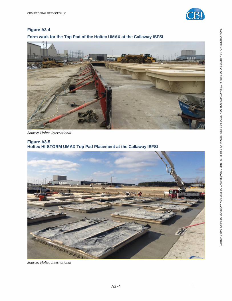
Figure A3-4 Form work for the Top Pad of the Holtec UMAX at the Callaway ISFSI
Source: Holtec International
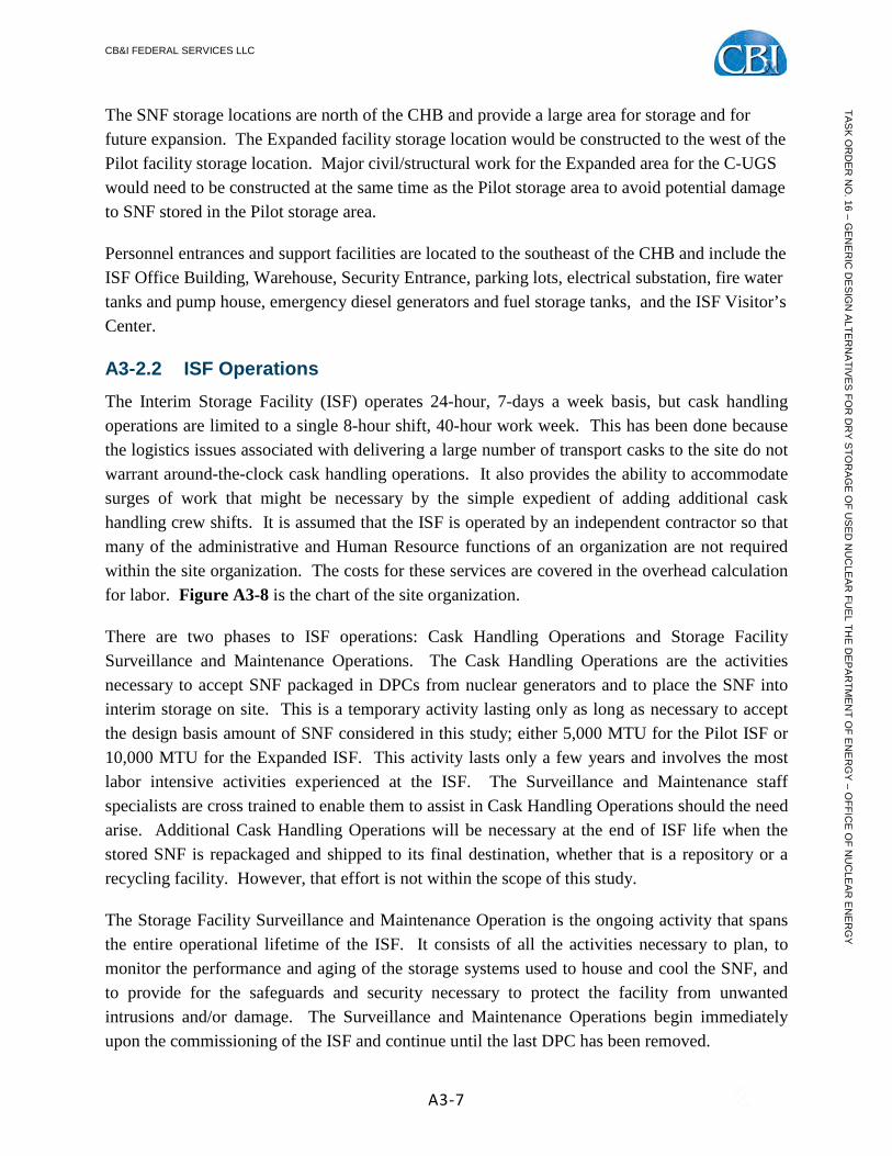
Figure A3-5 Holtec HI-STORM UMAX Top Pad Placement at the Callaway ISFSI
Source: Holtec International

CB&I FEDERAL SERVICES LLC
A3-5
TAS
K O
RD
ER
NO
. 16 – GE
NE
RIC
DE
SIG
N A
LTER
NA
TIVE
S FO
R D
RY
STO
RA
GE
OF U
SE
D N
UC
LEA
R FU
EL TH
E D
EP
AR
TME
NT O
F EN
ER
GY
– OFFIC
E O
F NU
CLE
AR
EN
ER
GY
Figure A3-6 Holtec HI-STORM UMAX, Completed Pad Construction, Callaway ISFSI
Source: Holtec International
A3-2.0 Concept of Operations A3-2.1 Facility Layout C-UGS is a straightforward application of the Holtec HI-STORM UMAX system for SNF storage. This is a new SNF storage technology but it has only been proposed for vertical storage canisters. The C-UGS alternative will propose an approach that will broaden the applicability of this concept to accept both vertical and horizontal DPCs. Figure A3-7 shows the C-UGS site layout.
The transport casks are delivered to the site by rail. Most likely, the railroad carrier will put the unit car at a siding off site and the ISF dedicated tug will be dispatched to retrieve the train. This small locomotive brings the railcars from the mainline siding to the Rail Interchange Siding Yard. At this point, the unit cars are disconnected and the security detachment who accompanied the ship is relieved. There is a powered derailer preventing unauthorized rolling stock onto the siding yard without clearance.

CB&I FEDERAL SERVICES LLC
A3-6
TAS
K O
RD
ER
NO
. 16 – GE
NE
RIC
DE
SIG
N A
LTER
NA
TIVE
S FO
R D
RY
STO
RA
GE
OF U
SE
D N
UC
LEA
R FU
EL TH
E D
EP
AR
TME
NT O
F EN
ER
GY
– OFFIC
E O
F NU
CLE
AR
EN
ER
GY
Figure A3-7 Conceptual Site Plan of the C-UGS Alternative
The individual transport cask bearing railcars are moved to the Railcar Security Inspection Area located at the entrance of the ISF protected area. There, site security officers will review the shipping paperwork and perform a thorough check of the rolling stock and the packaging to ensure that there is no contraband on the shipment. The railroad tracks have a powered derailer that is positioned at the gate to prevent unauthorized access into the protected area via rail. After the security inspection, the transport cask railcars are move into the SNF Delivery Rail Yard / Staging Area until the Cask Handling Crew is ready for them in the CHB.
The CHB is where the transition from the rolling stock to the storage area is begun. As a result, it is located at the intersection of the rail yard and the concrete storage area. It is accessible by two sets of rails, one for each railbay, and has cask transporter heavy haul routes to the storage area. The storage area is centrally located and laid out to provide easy access for the cask transport machines and the survey and security teams.
Transport casks are brought into the CHB from the staging area via the rollup doors on either the west or the east end of the railbay1. Materiel and supplies are brought in via the loading dock on the east side of the CHB. Lifting frames and other necessary adaptors to accommodate odd sized legacy SNF canisters are brought in by truck from the fabrication yard and handled via the railbays.
1 For this presentation, North is at the top of the figure. The ISF can be in any orientation, but for clarity of this description, North is up; East is right; etc.
CB&I FEDERAL SERVICES LLC
A3-7
TAS
K O
RD
ER
NO
. 16 – GE
NE
RIC
DE
SIG
N A
LTER
NA
TIVE
S FO
R D
RY
STO
RA
GE
OF U
SE
D N
UC
LEA
R FU
EL TH
E D
EP
AR
TME
NT O
F EN
ER
GY
– OFFIC
E O
F NU
CLE
AR
EN
ER
GY
The SNF storage locations are north of the CHB and provide a large area for storage and for future expansion. The Expanded facility storage location would be constructed to the west of the Pilot facility storage location. Major civil/structural work for the Expanded area for the C-UGS would need to be constructed at the same time as the Pilot storage area to avoid potential damage to SNF stored in the Pilot storage area.
Personnel entrances and support facilities are located to the southeast of the CHB and include the ISF Office Building, Warehouse, Security Entrance, parking lots, electrical substation, fire water tanks and pump house, emergency diesel generators and fuel storage tanks, and the ISF Visitor’s Center.
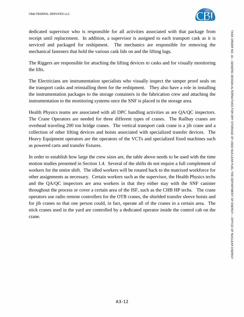
A3-2.2 ISF Operations The Interim Storage Facility (ISF) operates 24-hour, 7-days a week basis, but cask handling operations are limited to a single 8-hour shift, 40-hour work week. This has been done because the logistics issues associated with delivering a large number of transport casks to the site do not warrant around-the-clock cask handling operations. It also provides the ability to accommodate surges of work that might be necessary by the simple expedient of adding additional cask handling crew shifts. It is assumed that the ISF is operated by an independent contractor so that many of the administrative and Human Resource functions of an organization are not required within the site organization. The costs for these services are covered in the overhead calculation for labor. Figure A3-8 is the chart of the site organization.
There are two phases to ISF operations: Cask Handling Operations and Storage Facility Surveillance and Maintenance Operations. The Cask Handling Operations are the activities necessary to accept SNF packaged in DPCs from nuclear generators and to place the SNF into interim storage on site. This is a temporary activity lasting only as long as necessary to accept the design basis amount of SNF considered in this study; either 5,000 MTU for the Pilot ISF or 10,000 MTU for the Expanded ISF. This activity lasts only a few years and involves the most labor intensive activities experienced at the ISF. The Surveillance and Maintenance staff specialists are cross trained to enable them to assist in Cask Handling Operations should the need arise. Additional Cask Handling Operations will be necessary at the end of ISF life when the stored SNF is repackaged and shipped to its final destination, whether that is a repository or a recycling facility. However, that effort is not within the scope of this study.
The Storage Facility Surveillance and Maintenance Operation is the ongoing activity that spans the entire operational lifetime of the ISF. It consists of all the activities necessary to plan, to monitor the performance and aging of the storage systems used to house and cool the SNF, and to provide for the safeguards and security necessary to protect the facility from unwanted intrusions and/or damage. The Surveillance and Maintenance Operations begin immediately upon the commissioning of the ISF and continue until the last DPC has been removed.

CB&I FEDERAL SERVICES LLC
A3-8
TAS
K O
RD
ER
NO
. 16 – GE
NE
RIC
DE
SIG
N A
LTER
NA
TIVE
S FO
R D
RY
STO
RA
GE
OF U
SE
D N
UC
LEA
R FU
EL TH
E D
EP
AR
TME
NT O
F EN
ER
GY
– OFFIC
E O
F NU
CLE
AR
EN
ER
GY
Figure A3-8 Typical ISF Organization Chart
During the Cask Handling Operations, many supporting activities need to be performed by the ISF staff. The most directly related to the Cask Handling Activities is the inserts/adaptors that enable the legacy DPCs to fit properly in the cavity enclosure containers. Also, the fabrication of the Horizontal Cask Lifting Frames for the legacy horizontal DPCs cavity enclosure containers need to be produced in order to place horizontal DPCs in the C-UGS system. The steel components for the inserts/adaptors will be fabricated by the original vendor or contractors under the original vendor’s control. This is done to preserve the intellectual property. The C-UGS cavity enclosure containers will be redesigned by Holtec International to accept the largest DPC or DPC/Lifting Frame package that the ISF must accommodate.
The inserts/adaptors/lifting frames will be designed by the legacy DPC vendor to meet the design envelop of the C-UGS VVM. They are shipped to the site via rail and delivered to the insert/adaptor/lifting frame fabrication yard near the rail entrance to the protected area. After receipt inspection to ensure that the components meet specifications, the site fabrication crew will complete the assembly of the insert/adaptor/lifting frames. Since C-UGS uses the original storage canisters, the insert/adaptor/lifting frame Fabrication Crew needs to coordinate closely with the Operations Manager to ensure that the proper vertical storage insert/adaptor/lifting frame prepared far enough in advance of DPC placement. As a result, the insert/adaptor/lifting frame Fabrication Crew needs to be operating well ahead of the SNF acceptance process with a minimum of 30-days after the arrival of the steel components from the manufacturer until the insert/adaptor/lifting frame is ready to be used.

CB&I FEDERAL SERVICES LLC
A3-9
TAS
K O
RD
ER
NO
. 16 – GE
NE
RIC
DE
SIG
N A
LTER
NA
TIVE
S FO
R D
RY
STO
RA
GE
OF U
SE
D N
UC
LEA
R FU
EL TH
E D
EP
AR
TME
NT O
F EN
ER
GY
– OFFIC
E O
F NU
CLE
AR
EN
ER
GY
The procurement activities necessary to support the insert/adaptor/lifting frame production must be well ahead of the delivery of the SNF because the lead time for insert/adaptor/lifting frame material sourcing, delivery and final fabrication is on the order of 6 – 12 months. Orders must be placed with the appropriate DPC vendors in time to ensure that there is time fabricate and deliver the necessary components. Ideally, the system should support just-in-time delivery of all necessary insert/adaptor/lifting frame components that they can be used directly by the Cask Handling Crews. However, as a practical matter, the system should allow for buffer storage of these components in order to assure that SNF shipments are not held up by the lack of availability of inserts/adaptors/lifting frames. This means that the Supply Chain Management must identify the correct vendor, the correct model of DPC and the schedule for delivery in order to issue the purchase orders necessary to ensure the flow of material to the site. No shipment of SNF should be undertaken unless there is an appropriate insert/adaptor/lifting frame available on site.
Another major activity at the ISF necessary to support SNF placement is maintenance of the equipment necessary to perform the heavy lifts and heavy load movements necessary to fulfill the SNF handling function. While Cask Handling Operations are underway, the major equipment necessary to move the heavy loads around the ISF must be available and in working order. Cranes, carts and wheeled vehicles that handle DPCs need to be single failure proof and inspected and maintained rigorously to ensure operability and safety. The commercially available machines may need to be modified to make them more capable of sustaining the sustained work load during the early stages of the ISF life cycle.
In addition to physical labor, the ISF requires planning and engineering to support operations. As already described, engineering, procurement and insert/adaptor/lifting frame assembly activities need to be well ahead of actual SNF acceptance activities. The timescale of the work necessary to prepare the inserts/adaptors/lifting frames for the storage of SNF requires that the planning and engineering activities be performed nearly a year ahead of the SNF acceptance activities. Engineering activities are required for safety analyses and modifications to processes and materials to support SNF storage. Also, record keeping is required to identify where each DPC originates from, what it contains, the SNF characteristics and where it has been stored. In addition, all material certifications for SNF storage containers and other materials used for SNF handling need to be meticulously maintained for easy retrieval in the future.
Finally, the largest functional activity at the ISF is physical security. The security group needs to actively maintain the security of the site in addition to inspecting all materials coming onto the site. This security function is the largest single group of the organization and is a 24-7 operation. The C-UGS has a significant advantage over other pad-based storage alternatives in this area. Since the DPCs are stored below grade, it is easier for two lines of sight to be established over the SNF storage area in order to locate and to identify intruders. So, while a traditional overpack

CB&I FEDERAL SERVICES LLC
A3-10
TAS
K O
RD
ER
NO
. 16 – GE
NE
RIC
DE
SIG
N A
LTER
NA
TIVE
S FO
R D
RY
STO
RA
GE
OF U
SE
D N
UC
LEA
R FU
EL TH
E D
EP
AR
TME
NT O
F EN
ER
GY
– OFFIC
E O
F NU
CLE
AR
EN
ER
GY
system might require as many as four security locations to establish the necessary security coverage, the C-UGS can achieve it with only two. This results in a smaller security force than is needed for other pad-based storage systems. In addition, the IAEA oversight systems would be simplified since a single camera would be able to survey the entire storage area to assure inspectors that no diversion of potentially strategic materials occurs.
Table A3-1 is a listing of the site organization staff. The organizational staff would be adequate to support the activities at the ISF necessary to support the cask handling activities. This staff totals 132 but does not include the cask handling crew.
Table A3-1 Site Organization
Position Staff Position Staff Site Manager 1 Mechanical Engineers 4 Deputy Site Manager 1 I&C Engineers 1 Accounting Manager 1 Electrical Engineers 2 Planning Manager 1 Civil/Structural Engineers 4 QA – Manager 1 Quality Engineers 3 Contracts/Legal Manager 1 Buyers 2 Supply Chain Manager 1 Planners 3 Operations Manager 1 Security 46 ES&H Manager 1 Trainers 2 Engineering Manager 1 Railyard Operators 2 Training Manager 1 Supervisors 4 Security Manager 1 Mechanics 6 IT Manager 1 Electricians 4 DPC Handling Supervisors 1 CHB Facility Operators 10 Fabrication Supervisors 1 IT Technicians 2 Railyard Supervisors 2 Administration Assistants 2 Maintenance Supervisors 2 EMT 1 Health Physics Manager 1 RR Tug Engineers/Brakemen 4 Nuclear Safety Engineers 2 Overpack Fabrication Team 6 Health Physicists 2
Total 132
A3-2.3 Cask Handling Crew Size The Cask Handling Operations staff is dedicated to the movement of DPCs around the site. These operations are carried out by dedicated crews who focus on certain areas of the operation. This way, when multiple DPCs are processed each week, a crew learns specialized skills that will improve efficiency. The crews are: 1. the Railbay Crew, 2. the Cask Transfer Crew and 3. the Transporter Crew.

CB&I FEDERAL SERVICES LLC
A3-11
TAS
K O
RD
ER
NO
. 16 – GE
NE
RIC
DE
SIG
N A
LTER
NA
TIVE
S FO
R D
RY
STO
RA
GE
OF U
SE
D N
UC
LEA
R FU
EL TH
E D
EP
AR
TME
NT O
F EN
ER
GY
– OFFIC
E O
F NU
CLE
AR
EN
ER
GY
The Railbay Crew consists of the skilled crafts necessary to prepare the transport cask to be unloaded and later to be reassembled to be shipped back to the generator. These activities include receipt inspection of the as-received package, removal and storage of the impact limiters, removal and storage of the transport cask cover, and removal and storage of the tie-down straps. Then, the Railbay crew rigs the transport cask for lift by the overhead traveling bridge crane and, depending on the ultimate storage concept, either places it on the horizontal cask transporter or on the transfer cart in the CHB.
As soon as the transport cask is removed from the railcar, the Rail yard crew removes the empty railcar and brings in the next railcar for service. This is done as needed to maintain throughput and to assure that the Railbay Crew is fully engaged throughout the work week. Again, before the transport cask is returned to the railbay, the Railbay Crew will arrange with the Rail yard supervisor to have its original railcar returned to the Railbay. 2 Once the transport cask is returned to the railbay, the Railbay Crew inspects and surveys the cask, rigs it and repositions it back on the railcar, and then reassembles the transportation packaging for reshipment to the generator. This crew specializes in unloading the transport cask and repackaging empty transport casks for reshipment back to generators. There are two sets of Railbay Crews that can be used in either bay since the activities are identical.
The Cask Transfer Crews have to handle both vertical and horizontal storage system DPCs. The Transfer Crew works in the CHB and transfers the DPC from the transport cask into the transfer cask that includes the necessary insert/adaptor/lifting frame required to match the legacy DPC into the UMAX cavity enclosure containers. The transfer of vertical DPCs take place in the vertical transfer cells whereas the horizontal DPCs are inserted into lifting frames inside the transfer cask that has been rotated into the horizontal orientation on a transfer rig. Once the DPC is loaded into the transfer cask, the cask is handed off to the Transporter Crew. In addition, the Cask Transfer Crew also prepares the storage VVM and works with the Transporter Crew to place the DPC into storage.
The Transporter Crews operate the vertical canister transporters (VCTs) to move the storage transfer casks. The Transporter Crew positions the storage transfer cask in the receiving transfer cell or on the transfer fixture, and after it is loaded, picks the storage transfer cask and transports it to the storage location. Once at the storage location, the Transporter Crew operates the VCT in coordination with the Cask Transfer Crew to place the DPC into storage.
Table A3-2 shows the staffing for each major activity necessary to move SNF canisters from the transport cask to the storage area. These values are based on current experience with moving DPCs around operating nuclear sites to store the SNF at generator ISFSIs. Each DPC has a
2 It is assumed that the railcar and the transport cask need to remain paired.
CB&I FEDERAL SERVICES LLC
A3-12
TAS
K O
RD
ER
NO
. 16 – GE
NE
RIC
DE
SIG
N A
LTER
NA
TIVE
S FO
R D
RY
STO
RA
GE
OF U
SE
D N
UC
LEA
R FU
EL TH
E D
EP
AR
TME
NT O
F EN
ER
GY
– OFFIC
E O
F NU
CLE
AR
EN
ER
GY
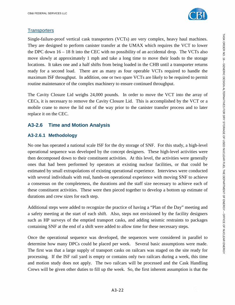
dedicated supervisor who is responsible for all activities associated with that package from receipt until replacement. In addition, a supervisor is assigned to each transport cask as it is serviced and packaged for reshipment. The mechanics are responsible for removing the mechanical fasteners that hold the various cask lids on and the lifting lugs.
The Riggers are responsible for attaching the lifting devices to casks and for visually monitoring the lifts.
The Electricians are instrumentation specialists who visually inspect the tamper proof seals on the transport casks and reinstalling them for the reshipment. They also have a role in installing the instrumentation packages to the storage containers in the fabrication crew and attaching the instrumentation to the monitoring systems once the SNF is placed in the storage area.
Health Physics teams are associated with all DPC handling activities as are QA/QC inspectors. The Crane Operators are needed for three different types of cranes. The Railbay cranes are overhead traveling 200 ton bridge cranes. The vertical transport cask crane is a jib crane and a collection of other lifting devices and hoists associated with specialized transfer devices. The Heavy Equipment operators are the operators of the VCTs and specialized fixed machines such as powered carts and transfer fixtures.
In order to establish how large the crew sizes are, the table above needs to be used with the time motion studies presented in Section 1.4. Several of the shifts do not require a full complement of workers for the entire shift. The idled workers will be rotated back to the matrixed workforce for other assignments as necessary. Certain workers such as the supervisor, the Health Physics techs and the QA/QC inspectors are area workers in that they either stay with the SNF canister throughout the process or cover a certain area of the ISF, such as the CHB HP techs. The crane operators use radio remote controllers for the OTB cranes, the shielded transfer sleeve hoists and for jib cranes so that one person could, in fact, operate all of the cranes in a certain area. The stick cranes used in the yard are controlled by a dedicated operator inside the control cab on the crane.

CB&I FEDERAL SERVICES LLC
A3-13
TAS
K O
RD
ER
NO
. 16 – GE
NE
RIC
DE
SIG
N A
LTER
NA
TIVE
S FO
R D
RY
STO
RA
GE
OF U
SE
D N
UC
LEA
R FU
EL TH
E D
EP
AR
TME
NT O
F EN
ER
GY
– OFFIC
E O
F NU
CLE
AR
EN
ER
GY
Table A3-2, Basis of Staffing
Vertical DPCs -Unshielded DPCs in individual vaults Supervisor Mechanics Electricians Riggers Operations HP QA/QC Crane RR Ops Heavy Eq. Operator Security Total
Staff Duration
(hrs) 0) Plan of the Day and Safety Meeting 1 2 2 2 0 2 1 1 0 0 0 11 0.5 1) Receive transport cask on railcar at Cask Handling Building 1 2 2 0 1 2 1 0 2 0 2 13 1 2) Remove impact limiters and place in temporary storage 1 2 0 2 0 2 0 1 0 0 0 8 3 3) Upend and lift transport cask off of railcar and place on unloading cell transfer cart 1 0 0 2 0 2 0 1 0 0 0 6 2
3a) Remove railcar from Railbay 0 0 0 0 1 0 0 0 2 0 2 5 1 4) Unbolt and remove transport cask lid using jib crane 1 2 0 1 0 2 0 1 0 0 1 8 1
4a) Secure the transport cask and transfer cart seismically 1 2 0 2 0 0 1 1 0 0 0 7 0.5 4b) Plan of the Day and Safety Meeting 1 2 0 2 0 2 1 1 0 1 0 10 0.5 5) Attach lifting lug to top of DPC 1 2 0 2 0 2 1 1 0 0 0 9 1 6) Position transport cask transfer cart into unloading cell and close shield doors 1 0 0 1 0 0 0 0 0 1 0 3 1 7) Stage transfer cask in receiving cell using VCT 1 2 0 0 0 0 1 0 0 1 0 5 1 8) Close receiving cell shield doors 1 0 0 2 0 0 0 0 0 0 0 3 0.5 9) Position shielded transfer sleeve cart over unloading cell 1 0 0 2 0 0 1 0 0 1 0 5 0.5
10) Lower shield sleeve hoist and grapple DPC lifting lug 1 0 0 2 0 0 0 0 0 1 0 4 0.5 11) Raise DPC into shield sleeve 1 0 0 2 0 2 1 0 0 1 0 7 1 12) Position shielded transfer sleeve cart over transfer cask in receiving cell 1 0 0 2 0 0 1 0 0 1 0 5 0.5 13) Lower DPC into transfer cask, release grapple, and retract hoist 1 0 0 2 0 2 0 0 0 1 0 6 1 14) Remove lifting lug from DPC 1 2 0 2 0 0 0 1 0 0 0 6 0.5
14a) Secure the DPC and the transfer cask seismically 1 2 0 2 0 0 1 1 0 0 0 7 0.5 14b) Plan of the Day and Safety Meeting 1 2 2 2 0 2 1 1 0 1 0 12 0.5 15) Pick up transfer cask and transfer to underground storage cell using VCT 1 0 0 2 0 0 0 0 0 1 0 4 2 16) Install docking collar at underground storage cell 1 2 0 2 0 0 1 1 0 1 0 8 2 17) Dock transfer cask to underground storage cell and remove rigging 1 0 0 2 0 2 0 0 0 1 0 6 0.5 18) Rig DPC to VCT for vertical lift and hoist 1 0 0 2 0 0 0 0 0 1 0 4 0.5 19) Remove transfer cask base using docking collar 1 2 0 2 0 0 0 1 0 1 0 7 0.5 20) Lower DPC into underground storage cell 1 0 0 2 0 0 1 0 0 1 0 5 1 21) Access top of DPC (by ladder inside transfer cask) and remove rigging 1 2 0 2 0 2 0 0 0 0 0 7 0.5 22) Withdraw DPC rigging and replace transfer cask base 1 2 0 2 0 0 0 0 0 0 0 5 0.5 23) Re-rig transfer cask to VCT and undock from underground storage cell 1 2 0 2 0 0 0 0 0 0 0 5 1 24) Install Closure Lid on CEC 1 2 0 2 0 0 1 1 0 0 0 7 1
24a) Turnover to Operations 1 0 2 0 2 2 1 0 0 0 0 8 24 24b) Plan of the Day and Safety Meeting 1 2 2 2 0 2 1 1 0 1 0 12 0.5 25) Return VCT to CHB 1 0 0 0 0 0 0 0 0 1 0 2 1 26) Open unloading cell shield doors and position transfer cart under jib crane 1 0 0 2 0 0 0 0 0 0 0 3 1 27) Install transport cask lid 1 2 0 2 0 0 1 1 0 1 1 9 1 28) Lift transport cask and transfer to maintenance 1 0 0 2 0 0 0 1 0 1 0 5 1
28a) Survey and wipedown Transport Cask 1 0 0 0 0 2 0 0 0 0 0 3 1 28b) Reposition Empty Railcar to Railbay 0 0 0 0 1 0 0 0 2 0 2 5 1 29) Lift transport cask and place on railcar 1 2 2 2 0 0 0 1 0 1 0 9 1 30) Install impact limiters on transport cask 1 2 0 2 0 0 1 1 0 0 0 7 2 31) Release railcar for shipment 1 0 0 0 1 2 1 0 2 0 2 9 1
* These categories are loaned to the Cask Handling Crew

CB&I FEDERAL SERVICES LLC
A3-14
TAS
K O
RD
ER
NO
. 16 – GE
NE
RIC
DE
SIG
N A
LTER
NA
TIVE
S FO
R D
RY
STO
RA
GE
OF U
SE
D N
UC
LEA
R FU
EL TH
E D
EP
AR
TME
NT O
F EN
ER
GY
– OFFIC
E O
F NU
CLE
AR
EN
ER
GY
Table A3-2, Basis of Staffing (Cont’d)
Horizontal DPCs -DPCs in lift frames in individual vaults Supervisor Mechanics Electricians Riggers Operations HP QA/QC Crane RR Ops Heavy
Eq. Operator
Security Total Staff Duration
0) Plan of the Day and Safety Meeting 1 2 2 2 0 2 1 1 0 0 0 11 0.5 1) Receive transport cask at Cask Handling Building 1 2 2 0 1 2 1 0 2 0 2 13 1 2) Remove impact limiters and place in temporary storage 1 2 0 2 0 0 0 1 0 0 0 6 3 3) Upend and lift transport cask off of railcar and downend on transfer fixture 1 0 0 2 0 0 0 1 0 0 0 4 2 4) Remove Transport Cask Lid 1 2 0 2 0 2 0 1 0 0 0 8 1
4a) Remove railcar from Railbay 0 0 0 0 1 0 0 0 2 0 2 5 1 5) Stage transfer cask on upright transfer fixture using VCT 1 2 0 2 0 0 0 0 0 0 0 5 1 6) Load lifting frame into transfer cask using jib crane 1 0 0 2 0 0 0 1 0 0 0 4 1 7) Downend transfer cask on transfer fixture 1 0 0 2 0 0 0 1 0 0 0 4 1
7a) Secure the transport cask and the transfer fixture seismically 1 2 0 2 0 0 1 0 0 0 0 6 0.5 7b) Plan of the Day and Safety Meeting 1 2 0 2 0 2 1 1 0 1 0 10 0.5 8) Dock transfer sleeve on horizontal transfer cart with transport cask 1 0 0 2 1 2 0 0 0 0 0 6 1 9) Push DPC from transport cask into transfer sleeve using ram mounted to fixed rack 1 0 0 2 1 0 0 0 0 0 0 4 1
10) Decouple horizontal transfer cart from transport cask and close shield door 1 0 0 2 1 2 0 0 0 0 0 6 0.5 11) Roll horizontal transfer cart onto turntable and rotate 180° 1 0 0 2 1 0 0 0 0 0 0 4 0.5 12) Roll horizontal transfer cart to upending cell and dock storage/transfer cask on upender 1 0 0 2 1 0 0 0 0 0 0 4 0.5 13) Push DPC from transfer sleeve into lift frame in storage/transfer cask 1 0 0 2 1 0 0 0 0 0 0 4 1 14) Unbolt docking collar from storage/transfer cask and undock horizontal transfer cart 1 0 0 2 1 0 0 0 0 0 0 4 1 15) Upend storage/transfer cask w/ DPC 1 0 0 2 1 0 0 0 0 0 0 4 0.5 16) Install storage/transfer cask lid using jib crane in upender transfer cell 1 2 0 2 0 2 1 1 0 0 0 9 1
16a) Secure the transfer cask seismically 1 2 0 2 0 0 1 1 0 0 0 7 0.5 16b) Plan of the Day and Safety Meeting 1 2 2 2 0 2 1 1 0 1 0 12 0.5 17) Pick up transfer cask and transfer to underground storage location using VCT 1 0 0 2 0 0 0 0 0 1 0 4 2 18) Install docking collar at underground storage location 1 0 0 2 0 0 0 1 0 0 0 4 2 19) Dock transfer cask to underground storage location and remove rigging 1 2 0 2 0 0 0 0 0 1 0 6 0.5 20) Rig lift frame to VCT for vertical lift and hoist 1 0 0 2 0 0 0 0 0 1 0 4 0.5 21) Remove transfer cask base using docking collar 1 2 0 2 0 0 0 1 0 0 0 6 0.5 22) Lower DPC into underground storage location 1 0 0 2 0 0 1 0 0 1 0 5 1 23) Access top of DPC (by ladder inside transfer cask) and remove rigging 1 2 0 2 0 2 0 0 0 1 0 8 0.5 24) Withdraw DPC rigging and replace transfer cask base 1 2 0 2 0 0 0 1 0 1 0 7 0.5 25) Re-rig transfer cask to VCT and undock from underground storage location 1 2 0 2 0 0 0 0 0 1 0 6 1 26) Install underground storage location cover 1 2 0 2 0 0 1 1 0 0 0 7 1
26a) Turnover to Operations 1 0 2 0 2 2 1 0 0 0 0 8 24 26b) Plan of the Day and Safety Meeting 1 2 2 2 0 2 1 1 0 1 0 12 0.5 27) Return VCT to CHB 1 0 0 2 0 0 0 0 0 1 0 4 1 28) Install transport cask lid 1 2 2 2 0 0 1 1 0 0 0 9 1 29) Lift transport cask and transfer to maintenance 1 0 0 2 0 0 0 1 0 0 0 4 1
29a) Survey and wipedown Transport Cask 1 0 0 0 0 2 0 0 0 0 0 3 1 29b) Reposition Empty Railcar to Railbay 0 0 0 0 1 0 0 0 2 0 2 5 1 30) Lift transport cask and place on railcar 1 2 2 2 0 0 0 1 0 0 0 8 1 31) Install impact limiters on transport cask 1 2 0 2 0 0 1 1 0 0 0 7 2 32) Release railcar for shipment 1 0 0 0 1 2 1 0 2 0 2 9 1
* These categories are loaned to the Cask Handling Crew

CB&I FEDERAL SERVICES LLC
A3-15
TAS
K O
RD
ER
NO
. 16 – GE
NE
RIC
DE
SIG
N A
LTER
NA
TIVE
S FO
R D
RY
STO
RA
GE
OF U
SE
D N
UC
LEA
R FU
EL TH
E D
EP
AR
TME
NT O
F EN
ER
GY
– OFFIC
E O
F NU
CLE
AR
EN
ER
GY
The results of this effort are summarized in Table A3-3 below. This staffing estimate is approximate since not all crafts are required for an entire shift. Also, some intermediate steps do not require a certain craft, but in reality, they do not disappear. These interruptions are ignored because they provide opportunities for breaks for the workers and do not materially impact the assessment. The ISF labor pool will be a matrix structure where necessary craft and managers will be drawn from the site organization staff as necessary to achieve the desired operations. This is an obvious requirement because of the variability in the Cask Handling Crew size by shift in Table A3-3. Based on this study, the site organization staff will need to be increased by 53 workers to achieve the desired ISF throughput during the cask handling phase of the facility’s life cycle. This results in a total ISF staff of 185.
Table A3-3 Cask Handling Crew Makeup
Craft Shift 1 Shift 2 Shift 3 Shift 4 Shift 5 Maximum* Supervisor 5 5 5 5 5 5 Mechanics 10 10 10 10 10 10 Electricians 4 4 4 4 4 4 Riggers 14 14 14 14 14 14 HP 8 8 8 8 8 8 QA/QC 4 4 4 4 4 4 Crane Operator 4 4 4 4 4 4 Heavy Eq. Operator 4 4 4 4 4 4 Totals 53 53 53 53 53 53 * To the nearest whole person
A3-2.4 Material Handling Flow Diagram Figure A3-9 is a representation of the material handling flow for the C-UGS alternative for the ISF. It describes the material flows of the operation. The central flow is the movement of DPCs containing SNF to the site. But equally important to the operations of the ISF are the material flow necessary to support the production of suitable storage insert/adaptor/lifting frames to place the DPCs into after being accepted by the site for storage. The vertical storage adaptors are prefabricated by the vendors and shipped to the site as steel structures packaged to protect them during transit. These adaptors are only required for legacy DPCs that are much smaller than the current DPCs. The need for the adaptor will be part of the licensing basis for the C-UGS design. The site crew will inspect these packages to accept them as undamaged and then will complete the fabrication in accordance with the vendor’s specification. For horizontal storage systems, the site fabrication crew needs to complete the fabrication of the lifting frames using the vendor’s design and components. Again, the lifting frames need to be designed to fit the legacy DPC to prevent unacceptable clearances.

CB&I FEDERAL SERVICES LLC
A3-16
TAS
K O
RD
ER
NO
. 16 – GE
NE
RIC
DE
SIG
N A
LTER
NA
TIVE
S FO
R D
RY
STO
RA
GE
OF U
SE
D N
UC
LEA
R FU
EL TH
E D
EP
AR
TME
NT O
F EN
ER
GY
– OFFIC
E O
F NU
CLE
AR
EN
ER
GY
Figure A3-9 Cask Handling Material Handling Flow Diagram3
The largest operations challenge for the C-UGS alternative is controlling the supply chain to ensure that the proper adaptor/lifting frame is available to match the DPC being received from the generator. The licensability of the final DPC is based on the conformance of the storage system with the original licensed dry storage system. As described in Section 2.2 above, the preparation time for a storage system is at least a month after receipt of the hardware from the storage system vendor. The lead time for this shipment could be six to twelve months. Therefore, up to a year ahead of the receipt of the SNF at the site, the supply chain manager needs to place an order for the necessary storage system adaptor/lifting frame components. This means that the ISF staff needs to know well in advance of delivery what vendor and what model of DPC system is needed. The coordination of the supply chain for the Insert/adaptor/lifting frame Fabrication and the SNF storage operations will be the largest management challenge for this design alternative.
3 Remediation is not part of this study’s work scope and is not addressed other than to note that the packages are not accepted on site regardless of their condition.

CB&I FEDERAL SERVICES LLC
A3-17
TAS
K O
RD
ER
NO
. 16 – GE
NE
RIC
DE
SIG
N A
LTER
NA
TIVE
S FO
R D
RY
STO
RA
GE
OF U
SE
D N
UC
LEA
R FU
EL TH
E D
EP
AR
TME
NT O
F EN
ER
GY
– OFFIC
E O
F NU
CLE
AR
EN
ER
GY
A3-2.5 Operation Sequence and Radiological Doses
A3-2.5.1 Operational Sequence
Cask handling operations are a series of heavy lifts and heavy equipment movements that move the SNF in sealed DPCs from the rail head to the storage area. The operational sequence was benchmarked against ISFSI operations at operating nuclear plants. Although no one has actually performed all of the operations at an ISF, each operation has a precedent established in the nuclear industry. The crew sizes and the durations necessary to perform each activity therefore has basis. This benchmarking provides the underpinning supporting this operational sequence and the Time and Motion analysis the follows in Section 2.6.
Figure A3-10 shows the high-level schedule for the two storage concepts in C-UGS assuming 8-hour shifts. The operational sequence once the transport cask is accepted into the CHB can be divided into four large blocks:
1. Opening the transport cask 2. Moving the DPC into the Transfer device or system 3. Placement of the DPC in the cavity enclosure container and 4. Preparing for the turnaround of the transport cask.
Figure A3-10 High-Level Operational Sequences
Vertical DPCs Bare in individual vaults
Shift 1 Shift 2 Shift 3 Shift 4
Opening Transport Cask
Moving Canister to Storage Cask
Placement of DSC
Returning Transport Cask
Horizontal DPCs in lift frames in individual vaults
Shift 1 Shift 2 Shift 3 Shift 4
Opening Transport Cask
Moving Canister to Storage Module
Placement of DSC
Returning Transport Cask

CB&I FEDERAL SERVICES LLC
A3-18
TAS
K O
RD
ER
NO
. 16 – GE
NE
RIC
DE
SIG
N A
LTER
NA
TIVE
S FO
R D
RY
STO
RA
GE
OF U
SE
D N
UC
LEA
R FU
EL TH
E D
EP
AR
TME
NT O
F EN
ER
GY
– OFFIC
E O
F NU
CLE
AR
EN
ER
GY
It should be noted that this is essentially a three shift exercise regardless of the original storage concept used. (The slight overlap into the fourth shift is the return of the empty VCT to the CHB; a non-critical path activity.) Once the transport cask is received in the CHB, the most time consuming operation is unpacking the transport cask from the railcar. This is a very labor intensive process that requires the removal of the impact limiters, the cask cover and the hold down straps. This process takes an entire 8-hour shift to accomplish. It also monopolizes the use of the OTB crane in each railbay.
The vertical DPCs are transferred into the necessary insert/adaptor required to secure the legacy DPC in the cavity enclosure container in the concrete array inside the transfer cask.4. This is accomplished in the CHB by use of two adjacent transfer cells via an access port in their roofs. The insert/adaptor is prepositioned in the transfer cask and the transfer cask is placed in the receiving cell of the transfer cell by the VCT. A lifting lug is affixed to the top of the DPC while it is still in the transport cask. Then the transport cask is placed in the transfer cell via a transfer cart. The shield doors are closed and the DPC is withdrawn from the transport cask up into a transfer cask located above the access port. Once the DPC is in the transfer cask, the transfer cask is repositioned over the receiving cell access port and the DPC is lowered into the storage transfer cask.
The lifting lug is removed from the DPC and the storage transfer cask is picked by the VCT. Once the storage transfer cask is securely loaded into the VCT, the VCT is secured because the transfer takes nearly an entire shift. Then the VCT picks the storage cask and transports it to and places it in the storage area. If the seismic requirements dictate, the storage insert/adaptor/lifting frame may be secured to the storage area.
Horizontal DPCs are transferred differently. The top cover plate of a Horizontal DPC is not compatible with the lifting lug necessary to lower the DPC into the VVM. Therefore, the DPC must be loaded into a lifting frame that is compatible with the lifting lug. The lifting frame is custom designed for the legacy Horizontal DPC and is prepositioned in the transfer cask. The transfer cask with loading frame is placed on the transfer fixture that rotates the cask over into the horizontal. The transport cask is placed in the other end of the transfer fixture and rotated into the horizontal. The transport cask is pressed into an indexing fixture that aligns the transport cask with the lifting frame in the transfer cask. A hydraulic ram similar to the ones provided on Horizontal Cask Transporters is part of the transfer fixture. It indexes with the ram grapple ring on the bottom of the horizontal DPC and pushes the DPC into the lifting frame within the storage transfer cask. The storage transfer cask is rotated into the vertical and the lifting lug is bolted to the top of the lifting frame. The transfer cask is then picked by the VCT in a manner similar to
4 It should be noted that for DPCs that are significantly different than the standard, it is possible to use a different enclosure wall or other internals of the UMAX CEC instead of inserts.

CB&I FEDERAL SERVICES LLC
A3-19
TAS
K O
RD
ER
NO
. 16 – GE
NE
RIC
DE
SIG
N A
LTER
NA
TIVE
S FO
R D
RY
STO
RA
GE
OF U
SE
D N
UC
LEA
R FU
EL TH
E D
EP
AR
TME
NT O
F EN
ER
GY
– OFFIC
E O
F NU
CLE
AR
EN
ER
GY
the vertical DPC. Once again, this transfer takes nearly an entire shift, so the VCT is secured before the end of the shift.
In both cases, the transport cask is returned to the railbay where it is surveyed and inspected for damage. On the following shift, the transport cask is mated with its original railcar and the shipping package is reassembled: tie-down straps are installed, the transport cask cover is secured and the impact limiters are reinstalled. This process takes about one shift to accomplish.
At the beginning of the next shift, the VCT begins the trip to the storage location. At the same time, the Cask Transfer Crew begins to prepare the VVM to receive the DPC. A 15 ton gantry crane is positioned to remove the Closure Lid. The gantry crane’s span is enables the crane to maneuver in gaps between the Closure Lids in the storage array. Once the Closure Lid has been removed, the internals of the VVM will be inspected to ensure that there is no debris or water in the cavity. Depending on the final geometries of the site, the crew may need to remove the exhaust stacks from the Closure lids between the storage location and the Haul Road to prevent damage.
A mating collar is placed on the top of the CEC. It provides both shielding and the Mating Device that captures the transfer cask’s bottom lid. The VCT places the transfer cask on top of the Mating Device. It is bolted to the Mating Device while the VCT hoist is rerigged to grapple the lifting lug on the DPC. The hoist lifts the DPC slightly to unload the bottom lid. The lid is unbolted from the top and lowered into the drawer of the Mating Device. The drawer is hydraulically actuated to move the lower lid out of the way allowing the DPC free access to the VVM. The VCT hoist lowers the DPC into the VVM and verifies that it is fully seated in the VVM.
The hoist ungrapples the lifting lug and returns to the full up position. The storage transfer cask is rigged to the VCT hoist. The Mating Device closes its drawer and the lower lid is reattached to the bottom of the storage transfer cask. The VCT backs out of the storage array using the same path as it used to approach the storage location. The Mating Device is partially opened allowing workers to remove the lifting lug and to plug any empty bolt holes on the top of the canister/lifting frame. When all of the rigging has been removed from the VVM, the Mating Device’s drawer is removed by the gantry crane and move back to storage. The Closure Lid is then replaced on the storage location and the DPC is turned over to operations for a 24-hour observation period. The area is returned to its original condition and the VCT is returned to the CHB to pick up its next DPC.

CB&I FEDERAL SERVICES LLC
A3-20
TAS
K O
RD
ER
NO
. 16 – GE
NE
RIC
DE
SIG
N A
LTER
NA
TIVE
S FO
R D
RY
STO
RA
GE
OF U
SE
D N
UC
LEA
R FU
EL TH
E D
EP
AR
TME
NT O
F EN
ER
GY
– OFFIC
E O
F NU
CLE
AR
EN
ER
GY
A3-2.5.2 Limits to Operation
Railbay
C-UGS Cask Handling Operations are a three shift process. Two of those shifts take place in the railbay. Therefore, the railbay is central to ISF operation and its design limits the ISF throughput. If there were only one railbay that could accommodate only one railcar, the ISF could only process about ten DPCs every four weeks assuming shuffling of railcars to maintain workflow. If the three shift process began on day one, the next shipment could only be brought into the CHB on day four. That would permit the placement of two DPCs the first week but the second week would only place one DPC because the first shift would be dedicated to turning around the transfer cask allowing one DPC to be placed by midweek and the introduction of a second new transport cask by the fifth shift. Also, any outage that occurs will prevent any movement of transport casks.
Adding a second railbay doubles the ISF throughput to an average of five DPCs per week.
If there is an inventory of loaded transport casks awaiting processing in the ISF rail yard, this study assumes that the rail yard supervisor will work with the Railbay Crew to shuffle rolling stock so that there is always the correct railcar in the railbay for operations to be continuous and on-going. Of course, if there is only one car awaiting turnaround in the rail yard, then the car will be brought into the railbay and three shifts later, it will be removed from the railbay. If, on the other hand, there are several railcars awaiting turnaround, the unloaded railcar will be removed (or repositioned) to allow the introduction of a new loaded railcar into the railbay. All of these activities are required to prevent the railbay from being a choke point for the operations of the ISF.
Overhead Traveling Bridge Cranes
The railbay requires a heavy lift crane in order to maneuver the transport cask off of the railcar and onto the transfer cart or the transfer fixture in the CHB. It also requires a crane to reverse this process and to replace the transport cask onto the railcar. Two overhead traveling bridge (OTB) cranes were selected for the conceptual CHB model. One OTB crane assigned per railbay ensures that the Railbay Crews can operate unimpeded by outages waiting for the crane. In order to keep the height of the building reasonable, both OTB cranes would operate on the same rails enabling either crane to service either railbay. Obviously, a failure or outage of either of the OTB cranes would seriously impact the throughput of the ISF but this expedient permits some functionality in the event of an extended crane outage.
The availability of the OTB crane is the most limiting component to overall ISF throughput. Because the activities necessary to disassemble and to reassemble the shipping package for the transport cask, only one transport cask can be worked on at a time. This limits the ISF

CB&I FEDERAL SERVICES LLC
A3-21
TAS
K O
RD
ER
NO
. 16 – GE
NE
RIC
DE
SIG
N A
LTER
NA
TIVE
S FO
R D
RY
STO
RA
GE
OF U
SE
D N
UC
LEA
R FU
EL TH
E D
EP
AR
TME
NT O
F EN
ER
GY
– OFFIC
E O
F NU
CLE
AR
EN
ER
GY
throughput to 5 DPCs placed into storage per week. Even if the railbays could support multiple railcars under the OTB crane, the throughput is limited by the crane availability.
Canister Transfer Cells
The vertical storage system transfers require canister transfer cells to provide shielding and to simplify operations during the transfer of the DPCs from the transport cask into the vertical transfer casks to be transported to the CEC. Each canister transfer cell consists of a door to allow a transport cask on a transfer cart to enter and exit the cell and a door on the adjacent cell to allow a transfer cask to enter and exit the cell on a transfer cart. On the floor above the cells is a transfer area where a shielded transfer cart traverses on rails over the the two transfer ports in the transfer cell ceiling. The hoist on the shielded transfer cart grapples the lifting lug on the DPC and extracts it from the transport cask. Once the DPC is in the shielded transfer cart, the cart is repositioned over the receiving cell and the DPC is lowered into the storage transfer cask in the cell below. This transfer is essential to the C-UGS concept because the storage transfer cask is specially designed to interface with the CEC. There are at most two DPCs being transferred at any one time, there is a need for two Canister Transfer Cell pairs and two Shielded Transfer Cells. The actual CHB design in this study has additional cells in case of equipment failures or as potential storage areas for DPC with failures. These cells are not required for horizontal DPCs.
Horizontal DPC Transfer Fixture
The Horizontal DPC Transfer Fixture is a novel component for this study. While all of the components of this device are well understood from the Horizontal storage concepts, the horizontal storage modules are fixed and the HCTs are mobile. In this design, the Storage transfer cask is preloaded with a lifting frame and is placed in the upender and lowered into the horizontal position. A transfer sleeve, which is located on a mobile rail-mounted cart, is then moved next to the Horizontal Transfer Fixture and secured. The transport cask is down ended on the other end of the Horizontal Transfer Fixture and docked with the Transfer Sleeve. The DPC is pushed out of the Transport Cart into the Transfer Sleeve in the traditional manner. The Transfer Sleeve is undocked and rotated on a turntable and docked with the transfer cask. A hydraulic ram that pushes against a full-diameter pressure plate then pushes the DPC into the Storage transfer cask. This double transfer ensures that the fuel assemblies not stored upside down, which could be a licensing issue. In use of the lifting frame permanently converts the horizontal DPC into a DPC that can be handled in the vertical. This process is about a rapid as the vertical transfer using the vertical transfer vaults and enables the use of the C-UGS concept by DPC designed for horizontal storage. However, this process is not expected to be simple or automated. It eliminates the advantage of the horizontal approach from an operational point of view. In order to process DPCs from a Horizontal Storage legacy site, there must be two of these sets of equipment available. A third set may be required to allow for maintenance issues.
CB&I FEDERAL SERVICES LLC
A3-22
TAS
K O
RD
ER
NO
. 16 – GE
NE
RIC
DE
SIG
N A
LTER
NA
TIVE
S FO
R D
RY
STO
RA
GE
OF U
SE
D N
UC
LEA
R FU
EL TH
E D
EP
AR
TME
NT O
F EN
ER
GY
– OFFIC
E O
F NU
CLE
AR
EN
ER
GY
Transporters
Single-failure-proof vertical cask transporters (VCTs) are very complex, heavy haul machines. They are designed to perform canister transfer at the UMAX which requires the VCT to lower the DPC down 16 – 18 ft into the CEC with no possibility of an accidental drop. The VCTs also move slowly at approximately 1 mph and take a long time to move their loads to the storage locations. It takes one and a half shifts from being loaded in the CHB until a transporter returns ready for a second load. There are as many as four operable VCTs required to handle the maximum ISF throughput. In addition, one or two spare VCTs are likely to be required to permit routine maintenance of the complex machinery to ensure continued throughput.
The Cavity Closure Lid weighs 24,000 pounds. In order to move the VCT into the array of CECs, it is necessary to remove the Cavity Closure Lid. This is accomplished by the VCT or a mobile crane to move the lid out of the way prior to the canister transfer process and to later replace it on the CEC.
A3-2.6 Time and Motion Analysis
A3-2.6.1 Methodology
No one has operated a national scale ISF for the dry storage of SNF. For this study, a high-level operational sequence was developed by the concept designers. These high-level activities were then decomposed down to their constituent activities. At this level, the activities were generally ones that had been performed by operators at existing nuclear facilities, or that could be estimated by small extrapolations of existing operational experience. Interviews were conducted with several individuals with real, hands-on operational experience with moving SNF to achieve a consensus on the completeness, the durations and the staff size necessary to achieve each of these constituent activities. These were then pieced together to develop a bottom up estimate of durations and crew sizes for each step.
Additional steps were added to recognize the practice of having a “Plan of the Day” meeting and a safety meeting at the start of each shift. Also, steps not envisioned by the facility designers such as HP surveys of the emptied transport casks, and adding seismic restraints to packages containing SNF at the end of a shift were added to allow time for these necessary steps.
Once the operational sequence was developed, the sequences were considered in parallel to determine how many DPCs could be placed per week. Several basic assumptions were made. The first was that a large supply of transport casks on railcars was staged on the site ready for processing. If the ISF rail yard is empty or contains only two railcars during a week, this time and motion study does not apply. The two railcars will be processed and the Cask Handling Crews will be given other duties to fill up the week. So, the first inherent assumption is that the

CB&I FEDERAL SERVICES LLC
A3-23
TAS
K O
RD
ER
NO
. 16 – GE
NE
RIC
DE
SIG
N A
LTER
NA
TIVE
S FO
R D
RY
STO
RA
GE
OF U
SE
D N
UC
LEA
R FU
EL TH
E D
EP
AR
TME
NT O
F EN
ER
GY
– OFFIC
E O
F NU
CLE
AR
EN
ER
GY
logistics supply chain is adequate to fully challenge the capacity of the ISF. Secondly, this study only considers operations that are already developed and in operation at existing operating nuclear plant experience. No unusual enhancements were considered. The only exception is that the vertical DPC transfers were made in canister transfer cells rather than in temporary stack-ups out in the storage pad as is the case at nuclear plants. So, the CHB eliminated the steps routinely applied to vertical stack-ups with a simplified approach that is essentially the same. However, C-UGS did not consider automating the transfer or adding a great deal of remote sensors to the area to eliminate personnel exposures. (See A-OPS for these improvements)
A major consideration for the Time and Motion Analysis was that no operation involving the movement of a DPC would be started during a shift if it could not be completed by the end of that shift. This is necessary because the CHB does not operate continuously, so no load would be left hanging or in some other unstable condition that would jeopardize the integrity of the SNF or its confining structures in the event of a design basis event. Abandoning the DPC in mid-operation would leave the canister in a potentially compromised position without qualified canister handling expertise on hand in case of emergency. In addition, the DPC was assumed to be secured seismically at the end of each shift.
As stated earlier, this study considers only a single 8-hour shift per week with no overtime. Clearly, the throughput could easily be increased by adding workers and shifts, and indeed that would be a cost effective expedient if additional capacity is desired. However, a working assumption of this study is only a single, 40-hour shift is necessary per week. Based on the certain problems with the logistics of moving SNF to the site, it is considered that this is a reasonable approach.
A3-2.6.2 Conclusion
It was determined that the C-UGS throughput with all of the assumptions is 5 full-sized DPCs placed into storage each week. Several observations came out of the Time and Motion Analysis. First, the CHB requires two railbays with the ability to shuffle railcars into and out of the railbay daily. This is necessary to get the throughput because it takes an entire shift to open a shipment and an entire shift to repackage a transport cask for reshipment. In between these two evolutions, there is an entire shift where the railbays are idle unless a new shipment is moved in for processing. This way, the shipments are processed through the facility in a staggered manner in order to assure continuous operation.
Second, with the CHB having two railbays, it is the OTB cranes that determine the maximum throughput of the CHB. Two overhead traveling bridge cranes service the railbays; one for each bay. These cranes are both on the same rails to reduce overhead space, but they typically operate in a dedicated railbay only. If one of the cranes becomes unavailable for any reason, it is moved

CB&I FEDERAL SERVICES LLC
A3-24
TAS
K O
RD
ER
NO
. 16 – GE
NE
RIC
DE
SIG
N A
LTER
NA
TIVE
S FO
R D
RY
STO
RA
GE
OF U
SE
D N
UC
LEA
R FU
EL TH
E D
EP
AR
TME
NT O
F EN
ER
GY
– OFFIC
E O
F NU
CLE
AR
EN
ER
GY
into a maintenance position and the remaining crane can be used to maintain operations, albeit at a reduced throughput forced by the lack of crane availability.
Third, there needs to be four operable single-failure-proof vertical cask transporters on site to develop and maintain full ISF throughput. These are complicated lifting rigs and extremely slow moving machines. Their size and mass make them destructive of the road bed if they move too rapidly. Moreover, they are restrained from moving too rapidly when carrying DPCs in order to limit the potential impact should there be a failure of any kind. They become critical path constraints if any one of them is out of service. In addition, they are currently designed for a limited amount of duty. The ISF would use these machines far more than their design. This could force a great deal of maintenance to keep them available. Two spares are considered necessary for the long-term functionality of the ISF.
Finally, this concept is especially susceptible to weather and other environmental conditions during the loading process. Precipitation or blowing dust may preclude activities for extended periods of time. If these adverse conditions persist through period of the day that the work is being performed, it could have a significant impact on the ISF throughput.
Figure A3-11 below shows the schedules for the C-UGS alternatives. The activities on the Y-axis are the steps necessary to process the DPCs from when they enter the Cask Handling Building until the empty transport cask has been reinstalled on the railcar and removed from the CHB. The time across the top of the schedule is in hours. The red bars are critical path activities; the blue are near critical path activities. It has been assumed that it will take 24-hours of observations of the DPC once stored to accept the package. This activity is show as a green dashed line on this chart but is not really part of the cask handling crew’s scope. It is the hand-off to ISF Operations for long-term surveillance and safeguards. It will consist of a series of temperature, air flow and radiation measurements over the initial 24-hour period to validate that the expected performance has been achieved.
The schedules in Figure A3-11 were then placed in series and in parallel to establish the maximum throughput of the ISF. Three separate time motion study scenarios were considered: all vertical storage, all horizontal storage and a 50-50 mix of vertical and horizontal storage. The results of this effort are summarized in Figure A3-12. Since both the vertical and the horizontal time motion studies require approximately three shifts to complete a cycle and four weeks to cycle two railcars through the railbay, the best way to see what the ISF’s throughput would be is to lay out four weeks. In spite of small differences in the work scopes, the time motion studies showed a consistent 20 DPCs placed every four weeks, for an average of five DPCs per week. Since canisters contain about 11.1 MTU each, that is equivalent to 2,900 MTU per year, assuming no outages. Figure A3-12 summarizes the work plan at a high level. It shows the work pattern for a four week period. After four weeks, the pattern repeats.

CB&I FEDERAL SERVICES LLC
A3-25
TAS
K O
RD
ER
NO
. 16 – GE
NE
RIC
DE
SIG
N A
LTER
NA
TIVE
S FO
R D
RY
STO
RA
GE
OF U
SE
D N
UC
LEA
R FU
EL TH
E D
EP
AR
TME
NT O
F EN
ER
GY
– OFFIC
E O
F NU
CLE
AR
EN
ER
GY
Figure A3-11 - Time Motion Schedules for C-UGS

CB&I FEDERAL SERVICES LLC
A3-26
TAS
K O
RD
ER
NO
. 16 – GE
NE
RIC
DE
SIG
N A
LTER
NA
TIVE
S FO
R D
RY
STO
RA
GE
OF U
SE
D N
UC
LEA
R FU
EL TH
E D
EP
AR
TME
NT O
F EN
ER
GY
– OFFIC
E O
F NU
CLE
AR
EN
ER
GY
Figure A3-11 - Time Motion Schedules for C-UGS (Cont’d)

CB&I FEDERAL SERVICES LLC
A3-27
TAS
K O
RD
ER
NO
. 16 – GE
NE
RIC
DE
SIG
N A
LTER
NA
TIVE
S FO
R D
RY
STO
RA
GE
OF U
SE
D N
UC
LEA
R FU
EL TH
E D
EP
AR
TME
NT O
F EN
ER
GY
– OFFIC
E O
F NU
CLE
AR
EN
ER
GY
Figure A3-12 Typical Work Plan for C-UGS
Week 1 Week 2 Week 3 Week 4
Shift 1 Shift 2 Shift 3 Shift 4 Shift 5 Shift 1 Shift 2 Shift 3 Shift 4 Shift 5 Shift 1 Shift 2 Shift 3 Shift 4 Shift 5 Shift 1 Shift 2 Shift 3 Shift 4 Shift 5
Railbay #1 Transport Cask #1 Unload
DPC #1 Transfer
to storage
Transport Cask #1 Reload
Transport Cask #5 Unload
DPC #5 Transfer
to Storage
Transport Cask #5 Reload
Transport Cask #9 Unload
DPC #9 Transfer
to Storage
Transport Cask #9 Reload
Transport Cask #13 Unload
DPC #13 Transfer
to Storage
Transport Cask #13 Reload
Transport Cask #17 Unload
DPC #17 Transfer
to Storage
Transport Cask #17 Reload
Railbay #1 Transport Cask #2 Unload
DPC #2 Transfer
to Storage
Transport Cask #2 Reload
Transport Cask #6 Unload
DPC #6 Transfer
to Storage
Transport Cask #6 Reload
Transport Cask #10 Unload
DPC #10 Transfer
to Storage
Transport Cask #10 Reload
Transport Cask #14 Unload
DPC #14 Transfer
to Storage
Transport Cask #14 Reload
Transport Cask #18 Unload
DPC #18 Transfer
to Storage
Transport Cask #18 Reload
Railbay #2 Transport Cask #19 Reload
Transport Cask #3 Unload
DPC #3 Transfer
to storage
Transport Cask #3 Reload
Transport Cask #7 Unload
DPC #7 Transfer
to Storage
Transport Cask #7 Reload
Transport Cask #11 Unload
DPC #11 Transfer
to Storage
Transport Cask #11 Reload
Transport Cask #15 Unload
DPC #15 Transfer
to Storage
Transport Cask #15 Reload
Transport Cask #19 Unload
DPC #19 Transfer
to Storage
Railbay #2 DPC #20 Transfer
to Storage
Transport Cask #20 Reload
Transport Cask #4 Unload
DPC #4 Transfer
to Storage
Transport Cask #4 Reload
Transport Cask #8 Unload
DPC #8 Transfer
to Storage
Transport Cask #8 Reload
Transport Cask #12 Unload
DPC #12 Transfer
to Storage
Transport Cask #12 Reload
Transport Cask #16 Unload
DPC #16 Transfer
to Storage
Transport Cask #16 Reload
Transport Cask #20 Unload
NOTES: 1. The highlighted boxes show the critical path activity in the Railbays. Note that work is always on going in the railbays.
2. The railcars are removed after the work crews are done with them and replaced by the next railcar to be processed.
3. The cycle is three shifts plus an idle shift to allow for processing two railcars at once. So, the cycle is four shifts long.
4. This process is the same for all C-UGS options, i.e., all vertical, all horizontal or a mix.
5. The ISF can process 20 DPCs in four weeks; averaging 5 a week.

CB&I FEDERAL SERVICES LLC
A3-28
TAS
K O
RD
ER
NO
. 16 – GE
NE
RIC
DE
SIG
N A
LTER
NA
TIVE
S FO
R D
RY
STO
RA
GE
OF U
SE
D N
UC
LEA
R FU
EL TH
E D
EP
AR
TME
NT O
F EN
ER
GY
– OFFIC
E O
F NU
CLE
AR
EN
ER
GY
A3-3.0 Pilot ISF Construction The Pilot ISF will consist of a number of features and structures that will need to be constructed for the facility to operate. They include:
• ISF Site (with access road and utilities) • Railroad spur and yard • Storage area • Cask Handling Building • Protected Area (security boundary, cameras, intrusion detection and lighting) • Overpack fabrication area • Concrete batch plant • Administration building • Security/access control building • Warehouse/maintenance facilities
A3-3.1 ISF Site The Pilot ISF site is assumed to be placed on approximately one square mile of property. Not all of the land will require construction, only the area for the initial storage area. An access road and electrical utilities will need to be constructed into the property. The site access road will consist of an asphalt paved 2 lane road from the nearest highway into the ISF. The location of the site will determine if mechanical utilities (domestic water, wastewater, natural gas) can be supplied from local means or if these will need to be self-contained. A remote site requiring self-contained utilities can use water wells or trucked-in tanks of water depending on the underground water capability. Wastewater can be discharged through drain fields. Propane gas can be supplied if no natural gas lines are near the site.
The site will require an Owner Controlled Area (OCA) fence which will likely consist of a chain link fence to discourage trespassers from entering the site and keep animals out. The fence requires minimal construction and establishes a good facility boundary. Just inside the fence a gravel security road can be constructed to enable guard patrols around the site.
The purpose of the OCA is to establish the portion of the property that maintains a level of secured control. Within this boundary, security maintains control and patrols for unauthorized individuals. In addition, 10 CFR 72.106 requires that all SNF storage and handling operations be maintained at least 100 meters from the OCA boundary. All CSF functions are contained within this boundary.
CB&I FEDERAL SERVICES LLC
A3-29
TAS
K O
RD
ER
NO
. 16 – GE
NE
RIC
DE
SIG
N A
LTER
NA
TIVE
S FO
R D
RY
STO
RA
GE
OF U
SE
D N
UC
LEA
R FU
EL TH
E D
EP
AR
TME
NT O
F EN
ER
GY
– OFFIC
E O
F NU
CLE
AR
EN
ER
GY
A3-3.2 Railroad Spur and Yard The Pilot ISF will need railroad tracks from the mainline to receive incoming train consists and prepare for outgoing train consists. A rail portal at the Protected Area boundary and a rail yard near the storage area will also be required.
The purpose for the rail yard is to provide adequate railcar storage for incoming and outgoing SNF train consists, and access to the CHB. The rail yard must be designed to allow flexibility for maneuvering yard switchers, railcars, buffer cars, and escort cars.
It is assumed that the rail yard will consist of at least 4 tracks – 2 tracks to receive inbound trains and 2 tracks for staging outbound trains. The yard includes a runaround track to permit the yard switchers access around the tracks. The yard also includes a lead line and a spur off the lead line accessing the Cask Handling Building.
Construction of the rail yards will involve excavation, structural fill, potential geotextile materials to maintain soil stability, gradation to establish various elevations to ease railcar movements, heavy steel rail, ties, several rail turnouts, ballast placement, lighting, and other minor railroad related features.
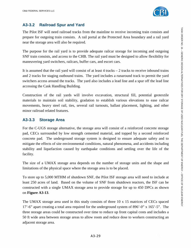
A3-3.3 Storage Area
For the C-UGS storage alternative, the storage area will consist of a reinforced concrete storage pad, CECs surrounded by low strength cemented material, and topped by a second reinforced concrete pad. The underground storage system is designed to ensure adequate safety and to mitigate the effects of site environmental conditions, natural phenomena, and accidents including stability and liquefaction caused by earthquake conditions and settling over the life of the facility.
The size of a UMAX storage area depends on the number of storage units and the shape and limitations of the physical space where the storage area is to be placed.
To store up to 5,000 MTHM of shutdown SNF, the Pilot ISF storage area will need to include at least 250 acres of land. Based on the volume of SNF from shutdown reactors, the ISF can be constructed with a single UMAX storage area to provide storage for up to 450 DPCs as shown on Figure A3-13.
The UMAX storage area used in this study consists of three 10 x 15 matrices of CECs spaced 17’-6” apart creating a total area required for the underground system of 896’-0” x 165’-5”. The three storage areas could be constructed over time to reduce up front capital costs and includes a 50 ft wide area between storage areas to allow room and reduce dose to workers constructing an adjacent storage area.
CB&I FEDERAL SERVICES LLC
A3-30
TAS
K O
RD
ER
NO
. 16 – GE
NE
RIC
DE
SIG
N A
LTER
NA
TIVE
S FO
R D
RY
STO
RA
GE
OF U
SE
D N
UC
LEA
R FU
EL TH
E D
EP
AR
TME
NT O
F EN
ER
GY
– OFFIC
E O
F NU
CLE
AR
EN
ER
GY
Figure A3-13 C-UGS Alternative – 5,000 MTHM UMAX Layout
A3-3.4 Cask Handling Building The C-UGS storage alternative would require some facility in order to offload transport casks from the railcars and perform canister transfer operations for all DPCs. The Cask Handling Building (CHB) provides these functions. The CHB for this report has been designed with 2 rail bays, 2 truck bays, 4 vertical canister transfer cells, 2 - 200 ton single-failure-proof overhead bridge cranes, laydown area for impact limiters, staging area for transport casks and office area. The CHB would be a reinforced concrete structure with thick walls to protect all SNF casks, canisters, overpacks, and cask-handling equipment from the effects of earthquakes, tornado winds, tornado-generated missiles, fire, and explosions. The throughput would be 3,000 MTHM/yr with one shift per day, 5 days per week.
A3-3.5 Protected Area The PA is an area within the OCA large enough to encompass the ISF rail yards, CHB, and underground system storage area. The PA consists of two physical barriers: (1) a security fence and (2) a nuisance fence separated by a 20-foot wide isolation zone. Within the isolation zone is an intrusion detection system that provides ground surveillance to detect any unauthorized entry into the PA. Assessment of unauthorized intruders is provided by illumination along the PA perimeter and throughout the storage area and a CCTV system, consisting of both fixed and pan-tilt-zoom cameras to monitor activities around the PA boundary from the security building.
The PA is surrounded by a passive vehicle barrier system (VBS) that is constructed of large concrete blocks to prevent any vehicles from getting near the PA boundary. The VBS is physically placed at a distance so that a pressure wave from a vehicle-born improvised explosive device cannot affect the storage containers or cask handling activities. Active VBSs are placed at large gates that accommodate railcars loaded with SNF transport casks or vehicles to prevent

CB&I FEDERAL SERVICES LLC
A3-31
TAS
K O
RD
ER
NO
. 16 – GE
NE
RIC
DE
SIG
N A
LTER
NA
TIVE
S FO
R D
RY
STO
RA
GE
OF U
SE
D N
UC
LEA
R FU
EL TH
E D
EP
AR
TME
NT O
F EN
ER
GY
– OFFIC
E O
F NU
CLE
AR
EN
ER
GY
any unauthorized entry. These VBSs can be lowered once the railcar or vehicles are inspected and cleared for entry.
Security equipment is typically powered from normal off-site power supplies. However, in the event of a loss of off-site power, an Uninterruptable Power System (UPS) consisting of batteries would be used to provide seamless power to all electronic security equipment. The UPS and site lighting would be backed up by an emergency diesel-powered generator located within the PA.
Bullet resistant enclosures would be situated at strategic locations within the PA to provide protected locations for security force personnel during a security event.
A3-3.6 Concrete Batch Plant A large amount of concrete will be required during construction of the underground system. This concrete can be supplied from a local concrete supplier or from a site concrete batch plant. Once the construction is complete, little use of the batch plant may needed until the next underground storage module is constructed.
If a site concrete batch plant is used, additional equipment associated with concrete supply operations such as concrete trucks, concrete pumper trucks, mobile cranes, backhoes for excavation, front-end loaders and dump trucks for moving soil, compaction equipment, powered concrete tools and small concrete finishing tools will be required.
A3-3.7 Site Support Buildings The Pilot ISF will need to include a number of support buildings. An administration building will need to be constructed to house managers, admin staff, engineers, document storage, licensing records, health physics personnel, radiological records, training rooms, etc.
A security/access control building will need to be constructed to house security personnel, security managers, the Central Alarm Station, safeguards information, etc. The building can be sited at the Protected Area boundary to provide access control for personnel entering the storage area. This most likely would include a badging station, explosion detectors, metal detector to monitor persons entering the secured area, x-ray machines to monitor materials brought onsite, and turnstiles delineating the PA boundary.
A warehouse/maintenance building will need to be constructed to stockpile materials shipped to the ISF for inspection equipment, general supplies, etc. This structure could also double as a maintenance building for general maintenance activities as well as transporter and canister handling equipment maintenance.

CB&I FEDERAL SERVICES LLC
A3-32
TAS
K O
RD
ER
NO
. 16 – GE
NE
RIC
DE
SIG
N A
LTER
NA
TIVE
S FO
R D
RY
STO
RA
GE
OF U
SE
D N
UC
LEA
R FU
EL TH
E D
EP
AR
TME
NT O
F EN
ER
GY
– OFFIC
E O
F NU
CLE
AR
EN
ER
GY
The ISF would also include a number of other features such as fire protection, potable water, sanitary drains, electrical power and distribution, and communications.
A3-4.0 Expansion to the Expanded ISF A3-4.1 Storage Area Impact
The Expanded ISF would store up to 10,000 MTHM, which includes the 5,000 MTHM from the Pilot ISF storage area plus an additional 5,000 MTHM. The expanded ISF would need to double the storage area size from 250 acres to 500 acres of land. See Figure A3-14.
The Pilot ISF consists of a 25 x 18 matrix of CECs for a total capacity of 450 storage units. The expanded ISF will need two of the same size storage area. The access road around the storage areas will also need to be doubled.
Figure A3-14 Expanded ISF Conceptual Plan of the C-UGS Alternative
Construction of the second 5,000 MTHM storage area could be performed outside of the Pilot ISF Protected Area to facilitate construction activities without stressing security. Once the new underground system is constructed, the PA could be expanded to encompass the additional

CB&I FEDERAL SERVICES LLC
A3-33
TAS
K O
RD
ER
NO
. 16 – GE
NE
RIC
DE
SIG
N A
LTER
NA
TIVE
S FO
R D
RY
STO
RA
GE
OF U
SE
D N
UC
LEA
R FU
EL TH
E D
EP
AR
TME
NT O
F EN
ER
GY
– OFFIC
E O
F NU
CLE
AR
EN
ER
GY
storage area. This type of construction will mean that a wide corridor will need to be placed between storage areas, and large separation corridors to ensure that construction workers receive as low as reasonably achievable (ALARA) radiation dose from the existing loaded storage units.
After the expansion has been completed, the PA would be expanded in size as required to accommodate the new storage area including fencing, intrusion detection system equipment, number of CCTV cameras and yard illumination. If designed for the expanded area, the vehicle barrier system would not need to be modified for the expanded ISF.
Electrical power would be similar to the Pilot ISF with some increases to account for the additional security and temperature monitoring equipment. The Uninterruptable Power System (UPS) and security backup emergency diesel-powered generator should not need to be modified as they should be sized to account for the expanded ISF during the Pilot ISF construction.
A3-4.2 Increased Throughput Impact The CHB constructed for the Pilot ISF has a throughput capacity of 3,000 MTHM/yr which may be adequate for an Expanded ISF. Even if the throughput requirements are increased to 4,500 MTHM/yr, the CHB would not need to be enlarged. Rather, adding a second shift would effectively double the throughput of the building to 6,000 MTHM.
Alternatively, adding weekend shifts but still maintain only 1 shift per day would effectively increase the CHB throughput to 7 canister transfers per week or 364 canisters per year. This translates into approximately 4,200 MTHM/yr, which is short of the 4,500 MTHM but may still be adequate depending on the shipment rates. Expansion to the Expanded ISF beyond a capacity of 10,000 MTHM will require a time and motion analysis to determine the throughput rate necessary to remove canisters from reactor sites. At that time the throughput requirements for the CHB can be assessed and shifts added to meet those requirements.
To expand the Pilot ISF, the rail yards, Administration Building Warehouse/Maintenance Building, Security/Access Control Building and other site infrastructure utilities may not require many modifications. Backup electrical power service for illumination and security of the larger storage area, additional security guards, increased CCTV and intrusion detection equipment are a few modifications that may be required to accommodate the expanded ISF. For example, these additions may require a larger Security/Access Control Building for the additional security personnel as well as a larger CAS for the increased CCTV and intrusion detection systems. However, if the Pilot ISF is designed with the understanding of the expanded ISF that doubles the storage area, then these items could easily be included in the initial design.
After the expansion, the ISF may need to procure additional vertical cask transporters (VCTs) to accommodate the expansion of the site. Although two VCTs may be able to handle the
CB&I FEDERAL SERVICES LLC
A3-34
TAS
K O
RD
ER
NO
. 16 – GE
NE
RIC
DE
SIG
N A
LTER
NA
TIVE
S FO
R D
RY
STO
RA
GE
OF U
SE
D N
UC
LEA
R FU
EL TH
E D
EP
AR
TME
NT O
F EN
ER
GY
– OFFIC
E O
F NU
CLE
AR
EN
ER
GY
throughput, it is recommended that the ISF should employ at least three transporters. With the continual work, it is very likely one transporter (on average) could be in maintenance status at all times and the third transporter could alleviate any backups that may occur.
A3-4.3 Modular Expansion Impact For underground storage, each of the underground storage areas could be considered modular units. These modular units are large and require construction activities be conducted at one time in concentrated phases. Although this requires capital costs upfront, once constructed no other construction activities are required until the next storage module is required.
A3-5.0 Performance of Structures, Systems and Components A3-5.1 Structural and Seismic Evaluation Seismic evaluations for the U-MAX storage system are performed to ensure that the storage system is capable of withstanding the accelerations generated by the design earthquake, that the system is sized to maintain structural integrity under loading applied by the DPC, that the system will transfer the inertia loading from the DPC to the earth around the storage system and that the storage system has sufficient engagement in the soil to prevent soil failure.
Seismic evaluations of the storage systems documented in vendor SAR determine the capacity to resist accelerations applied by the U-MAX system. The results of this comparison indicate that for the 0.25G earthquake, the capacities of the U-MAX storage system are within 20% of the maximum responses calculated at the grade elevation. In general, there is enough margin between the seismic capacity credited in the vendor SAR and the actual maximum seismic capacity at the material design limits to consider the storage systems qualified for the 0.25G earthquake demands.
For the 0.75G earthquake, the capacities of the U-MAX storage system will remain within the maximum responses calculated at grade elevation. Even with this higher acceleration, there is enough margin between the seismic capacity credited in the vendor SAR and the actual maximum seismic capacity at the material design limits to consider the storage systems qualified for the 0.75G earthquake demands.
A3-5.2 Thermal Evaluation The underground storage system primarily relies upon free convection passive cooling to reject the heat generated by the DPC it contains (see Figure A3-15). In order to introduce the flow of cooling air at the base of the DPC, the underground system utilizes a cylindrical sleeve which encircles the DPC mid-way between the interior surface of the CEC and the exterior surface of the DPC. The sleeve extends from the surface of the ground almost all the way down to the

CB&I FEDERAL SERVICES LLC
A3-35
TAS
K O
RD
ER
NO
. 16 – GE
NE
RIC
DE
SIG
N A
LTER
NA
TIVE
S FO
R D
RY
STO
RA
GE
OF U
SE
D N
UC
LEA
R FU
EL TH
E D
EP
AR
TME
NT O
F EN
ER
GY
– OFFIC
E O
F NU
CLE
AR
EN
ER
GY
bottom of the CEC. The air flows from the ground surface down the gap between the CEC wall and the outside of the sleeve, through the narrow opening at the bottom of the CEC, and up the gap between the DPC exterior surface and the sleeve interior surface. The air exhausts through vents in the concrete cap which sits on top of the CEC. The gaps are sized to provide sufficient flow to remove both the heat coming off of the exterior surface of the DPC and the heat coming off the sleeve which transfers from the DPC to the sleeve by radiation.
Figure A3-15 Passive cooling in a Holtec HI-STORM UMAX storage system
The thermal evaluation determined that the heat transfer capabilities of the underground silos will need to be analyzed to show that they will meet the allowable temperature limits since the gaps and the height of the air column between the DPC and the CEC which drives the air flow will have a range of diameters and heights of vertical DPCs, as well as horizontal DPCs in lift frames. However, since the heat generated by the fuel is below the design heat load for the DPC due to aging, the risk associated with the underground storage system design not meeting thermal performance requirements with shutdown SNF is considered low.
A detailed discussion of the thermal evaluation is provided in Section 6.2 of the report.

CB&I FEDERAL SERVICES LLC
A3-36
TAS
K O
RD
ER
NO
. 16 – GE
NE
RIC
DE
SIG
N A
LTER
NA
TIVE
S FO
R D
RY
STO
RA
GE
OF U
SE
D N
UC
LEA
R FU
EL TH
E D
EP
AR
TME
NT O
F EN
ER
GY
– OFFIC
E O
F NU
CLE
AR
EN
ER
GY
A3-5.3 Radiological Evaluation The exposures to radiation for the workers at the ISF were based on the time and motion study and the assumed average dose rates from the DPCs stored at the site. Once installed in their storage insert/adaptor/lifting frame, the doses to workers and to the public are quite small. However, during Cask Handling Operations, workers need to work on top of DPCs and near the transport cask and the transfer casks. As a security precaution, the plant security officers need to visually inspect the inside of the transport cask for contraband as soon as it is opened. In addition, workers on vertical cask storage units need to bolt a lifting lug directly onto the DPC and after it has been transferred to the storage insert/adaptor/lifting frame, it needs to be unbolted and the storage insert/adaptor/lifting frame lid needs to be bolted in place. In areas where the seismic loads are large enough to warrant it, workers sometimes need to bolt the vertical storage insert/adaptor/lifting frame to the pad. The air intakes on the vertical insert/adaptor/lifting frame are streaming areas with relatively high dose rates.
The cask handling crews on horizontal storage modules need to remove the storage module shield cover over the next location to be loaded. The interiors of the storage modules are not shielded so while the cover is off, radiation from the DPCs already stored in the module streams out of the opening making the area around the opening a high radiation protection zone. All subsequent activities necessary to mate the transport cask to the module are done in this high radiation protection zone. Once the DPC is installed and before the shield cover is reinstalled, a worker needs to reach into the module to install a seismic shear lug in the module to prevent the canister shifting toward the shield cover during a seismic event.
The time and motion study identified all of the steps necessary to be performed in sequence in order to move the DPC from the railbay to the storage. In addition to the sequencing and timing, the staff required for each step was developed from the experience with operating nuclear plant ISFSI operations. In the time and motion study, the number of people and the time required for each step was used to determine the throughput and the total staffing requirement. However, this detail was inappropriate for determining the radiation exposures. So, the staffing for each activity associated with moving the DPC was further decomposed into the individual subactivities necessary and the location of each member of the staff was identified relative to the DPC. For instance, the Supervisor, the Heavy Equipment Operator and the Crane Operator are never near the DPC. While the Mechanics, Riggers and QA/QC Inspectors are often in direct contact or close proximity to the SNF. Also, if a step takes an hour to accomplish, it may only involve a few minutes of exposure to the DPC. Experienced Rad Workers know how to perform work in a way that minimizes their exposures to radiation.
Table A3-4 below summarizes the radiological dose results of this analysis for the vertical and for the horizontal storage concepts as shown in Table 6.4.4.2 of Section 6.4. For the detailed

CB&I FEDERAL SERVICES LLC
A3-37
TAS
K O
RD
ER
NO
. 16 – GE
NE
RIC
DE
SIG
N A
LTER
NA
TIVE
S FO
R D
RY
STO
RA
GE
OF U
SE
D N
UC
LEA
R FU
EL TH
E D
EP
AR
TME
NT O
F EN
ER
GY
– OFFIC
E O
F NU
CLE
AR
EN
ER
GY
radiological information, see Appendix D-4. The doses are based on an approximate average design base fuel that could be present at the ISF. The design base dose values are used to evaluate each alternative storage method and provide an accurate comparison between alternatives. Note that after the DPC has been placed in storage, it is assumed that the dose rate to workers in the cask handling areas is near background levels and have a negligible contribution.
Table A3-4 Radiological Dose Per DPC to Worker by Category
Storage Alternative – C-UGS Craft
Mechanics Riggers Health Physics Operators Security Quality Totals
Vertical
176 68 54 0 11 3 313 Horizontal 197 91 50 0 12 0 350 * To the nearest whole person
These radiation doses represent maximum doses per DPC processing activities and are anticipated to decrease with operating experience.
A3-5.4 Design Life, Aging and Maintenance Evaluation Currently, storage systems may be designed for 40 to 100 years but are only permitted to be licensed for a period of up to 40 years. Prior to February 16, 2011, when 10 CFR 72.42, Duration of License; Renewal (for specific licenses) and 10 CFR 72.240, Conditions for Spent Fuel Storage Cask Renewal (for CoCs for general licenses) were revised to permit 40 year license durations, licenses and CoCs for storage systems had a duration of 20 years. Therefore, most of the storage systems currently in place at ISFSIs are only licensed for 20 years. In order to renew the license and extend the storage license, NUREG-1927, Standard Review Plan for Renewal of Spent Fuel Dry Cask Storage System Licenses and Certificates of Compliance (Reference A3-5) requires that an applicant demonstrate that the effects of aging will be adequately managed so that the intended safety function(s) of SSCs identified in the scope of license renewal will be maintained consistent with the current licensing basis for the period of extended operation. The NRC requires that an Aging Management Review (AMR) be performed that consists of identifying ISFSI components relied on for safety, susceptible materials in those components, environments to which susceptible materials are exposed, aging effects, and development of an aging management program to manage aging effects and protect against degradation of age-sensitive components (such as by performing inspections of age-sensitive components and replacing components that have a life expectancy of less than the license renewal period being requested in the anticipated environment). For purposes of this section, it is assumed that the original license has a duration of 20 years and a 40 year license extension is requested, so the licensee will need to demonstrate the in-scope component materials will

CB&I FEDERAL SERVICES LLC
A3-38
TAS
K O
RD
ER
NO
. 16 – GE
NE
RIC
DE
SIG
N A
LTER
NA
TIVE
S FO
R D
RY
STO
RA
GE
OF U
SE
D N
UC
LEA
R FU
EL TH
E D
EP
AR
TME
NT O
F EN
ER
GY
– OFFIC
E O
F NU
CLE
AR
EN
ER
GY
withstand the anticipated environment for a total of 60 years, or provide a plan for replacing age-sensitive components at acceptable analyzed intervals. If the initial license was for a 40 year duration, and a 40 year license extension is requested, then the licensee would need to demonstrate the in-scope components are acceptable for 80 years in the storage environment.
The AMR identifies susceptible materials of subcomponents in the in-scope SSCs that are exposed to environments that could cause age-related degradation. The functions required to be performed by the individual subcomponents of these in-scope SCCs (determined in previous section) are identified in applicable tables in this AMR section of the application for ISFSI license renewal.
The NRC’s Draft Revision 1 of NUREG-1927, Standard Review Plan for Renewal of Specific Licenses and Certificates of Compliance for Dry Storage of Spent Nuclear Fuel (Reference A3-6) explains the purpose of the AMR as follows:
“The purpose of the aging management review (AMR) is to assess the proposed aging management activities (AMAs) for structures, systems, and components (SSCs) determined to be within the scope of renewal. The AMR addresses aging mechanisms and effects1 that could adversely affect the ability of the SSCs (and associated subcomponents) from performing their intended functions during the period of extended operation. The reviewer should verify that the renewal application includes specific information that clearly describes the AMR performed on SSCs within the scope of renewal.”
Footnote 1 in this quotation states: “In order to effectively manage an aging effect, it is necessary to determine the aging mechanisms that are potentially at work for a given material and environment application. Therefore, the aging management review process identifies both the aging effects and the associated aging mechanisms that cause them.”
The license application needs to include an Aging Management Review (AMR) that is comprised of four major steps that are summarized as follows:
1) Identification of In-Scope Subcomponents Requiring AMR
Structures, Systems and Components (SSCs) within scope of the aging evaluation are identified as those that are 1) classified as important to safety (ITS), and 2) classified as not important to safety but whose failure could prevent an ITS function from being fulfilled. SSCs within scope are determined based on review of the ISFSI Materials License, ISFSI SAR, ISFSI Tech Specs, NRC’s SER for the ISFSI and docketed licensing correspondence related to the ISFSI.

CB&I FEDERAL SERVICES LLC
A3-39
TAS
K O
RD
ER
NO
. 16 – GE
NE
RIC
DE
SIG
N A
LTER
NA
TIVE
S FO
R D
RY
STO
RA
GE
OF U
SE
D N
UC
LEA
R FU
EL TH
E D
EP
AR
TME
NT O
F EN
ER
GY
– OFFIC
E O
F NU
CLE
AR
EN
ER
GY
2) Identification of Susceptible Materials and Applicable Environmental Conditions
For the subcomponents of in-scope SSCs that require AMR, the next step is identification of materials of construction susceptible to aging and the environments (e.g., temperature, pressure, radiation, wet vs. dry, etc.) that these materials normally experience.
3) Identification of Aging Mechanisms and Effects Requiring Management
Aging mechanisms potentially at work on susceptible materials in given environments (corrosion, cyclic stress fatigue, radiation embrittlement, etc.) are determined. Aging effects (manifestation of aging mechanisms) of material / environment combinations are compiled from industry and plant operating experience through use of industry standards and reference materials, including metallurgical literary references. During this process, the question is asked, are the potential aging effects credible given the identified materials and environmental conditions of storage?
4) Determination of Activities Required to Manage Aging Effects (Aging Management Program)
The final step in the AMR process involves the determination of activities necessary to manage the effects of aging. If the aging review determines that certain materials may not be able to support a 60 year life in the environment that they are normally exposed to, then an Aging Management Program needs to be established for those subcomponents to extend the life of the storage system to 60 years (such as by performing inspections of vulnerable subcomponents to determine their continued adequacy, or replacing the associated subcomponent at specified intervals).
Each of the four above steps of the AMR process are discussed in more detail in the following paragraphs.
A3-5.4.1 Aging Management Review (AMR)
Identification of In-Scope Components Requiring AMR
During this first step in the AMR process, the in-scope SSCs are further reviewed to identify and describe the subcomponents that support the SSC intended function. Intended functions of interest in the AMR are sub-criticality control, pressure boundary integrity (confinement of fission products), heat transfer, structural support (protection against environmental phenomena) and shielding. The subcomponents and associated intended functions are identified by reviewing the applicable current licensing basis (CLB) documentation sources.

CB&I FEDERAL SERVICES LLC
A3-40
TAS
K O
RD
ER
NO
. 16 – GE
NE
RIC
DE
SIG
N A
LTER
NA
TIVE
S FO
R D
RY
STO
RA
GE
OF U
SE
D N
UC
LEA
R FU
EL TH
E D
EP
AR
TME
NT O
F EN
ER
GY
– OFFIC
E O
F NU
CLE
AR
EN
ER
GY
SSCs and associated subcomponents within the scope of renewal fall into the following scoping categories:
(1) They are classified as important to safety (ITS), as they are relied on to do one of the following functions:
i. Maintain the conditions required by the regulations, specific license, or CoC to store spent fuel safely;
ii. Prevent damage to the spent fuel during handling and storage; or
iii. Provide reasonable assurance that spent fuel can be received, handled, packaged, stored, and retrieved without undue risk to the health and safety of the public.
These SSCs ensure that important safety functions are met for (1) confinement, (2) radiation shielding, (3) sub-criticality control, (4) heat-removal capability, (5) structural integrity, and (6) retrievability of the spent fuel.
(2) They are classified as not important to safety but, according to the design bases, their failure could prevent fulfillment of a function that is important to safety.
Subcomponents that perform or support any one of the identified intended functions will require an AMR. Those components that do not support an intended function can be excluded from further evaluation in the AMR with supporting justification. The SSCs within the scope of renewal are screened to identify and describe the subcomponents with intended functions. It should be recognized that SSC subcomponents may degrade by different modes, or have different criteria for evaluation from the overall component (i.e., different materials or environments). SSC subcomponents may also have different performance requirements for support of safety functions.
Typically, the application for ISFSI license renewal tabulates the results of the AMR, including a listing of subcomponents and the intended function provided by each subcomponent, material group, environment, aging effects requiring management and aging management activity required. The AMR results tables also identify subcomponents that did not support the SSC intended function and are not subject to AMR, with justification for their exclusion.
Identification of Materials and Environments
The second step of the AMR process requires the identification of materials of construction and the environments to which these materials are exposed, for the in-scope ISFSI subcomponents that require an AMR. Environmental data may include: temperature, wind, relative humidity, relevant atmospheric pollutants and deposits, exposure to precipitation, marine fog, salt, or water
CB&I FEDERAL SERVICES LLC
A3-41
TAS
K O
RD
ER
NO
. 16 – GE
NE
RIC
DE
SIG
N A
LTER
NA
TIVE
S FO
R D
RY
STO
RA
GE
OF U
SE
D N
UC
LEA
R FU
EL TH
E D
EP
AR
TME
NT O
F EN
ER
GY
– OFFIC
E O
F NU
CLE
AR
EN
ER
GY
exposure, radiation field (gamma and neutron), the service environment (e.g., embedded, sheltered, or outdoor), and gas compositions (e.g., external: air; internal: inert gas such as helium).
The environments to which components are exposed play a critical role in the determination of potential aging mechanisms and effects. A documentation review is required to quantify the environmental conditions to which the in-scope ISFSI SSCs are continuously or frequently exposed (conditions known to exist on a recurring basis). As noted in the next section, normal operating conditions are evaluated and not accident conditions.
The storage system FSAR is typically used to determine the intended functions and materials of construction for cask subcomponents that are in-scope of ISFSI license renewal. Additional documentation, drawings and technical reports should also be reviewed during the AMR process as required to obtain clarifications of the intended materials of construction and functions performed by in-scope ISFSI subcomponents.
The specific materials of construction for the cask and fuel assembly subcomponents requiring aging management review are identified and evaluated for the renewal period.
Identification of Aging Mechanisms and Effects Requiring Management
The third step in the AMR process is to identify the aging mechanisms and effects requiring management. A Material Aging Effects Report (MAER) is typically prepared for the storage system in question. This report needs to include aging mechanisms and effects that theoretically occur as well those that have actually occurred based on industry operating experience and the ISF operating experience for the appropriate material and environmental conditions. Aging effects are presented in this report in terms of material / environment combinations.
The environments considered in the evaluation are the environments that the subcomponents normally experience. Environmental stressors that are conditions not normally experienced, such as accident conditions, or that may be caused by a design problem, are considered event-driven situations and are not characterized as sources of aging. Such event-driven situations would be evaluated at the time of event, with corrective actions taken as necessary.
To effectively manage an aging effect, it is necessary to determine the aging mechanisms that are potentially at work for a given material and environment application. Therefore, the AMR process needs to address both the aging mechanisms as well as the aging effects. Selective mechanisms are only applicable under certain environmental conditions, such as high temperature or moisture. The identified aging mechanisms need to be characterized by a set of applicable conditions that must be met for the mechanism to occur and/or propagate. The application for ISFSI license renewal should identify aging effects based on the aging
CB&I FEDERAL SERVICES LLC
A3-42
TAS
K O
RD
ER
NO
. 16 – GE
NE
RIC
DE
SIG
N A
LTER
NA
TIVE
S FO
R D
RY
STO
RA
GE
OF U
SE
D N
UC
LEA
R FU
EL TH
E D
EP
AR
TME
NT O
F EN
ER
GY
– OFFIC
E O
F NU
CLE
AR
EN
ER
GY
mechanisms potentially at work in given environments on susceptible subcomponent materials (e.g., general corrosion of carbon steel, stress corrosion cracking and crevice and pitting corrosion of stainless steel, cyclic stress fatigue, radiation embrittlement, boron depletion of neutron absorber due to neutron flux, etc.). Aging effects (manifestation of aging mechanisms) of material / environment combinations are compiled from industry and plant operating experience through use of industry standards and reference materials, including metallurgical literary references. The majority of aging mechanisms will be extracted from industry documents (including NRC and EPRI) for the applicable material/environmental combinations. For instance, the EPRI Dry Cask Characterization Project final report (Reference A3-7) is a primary source for fuel assembly and dual purpose canister internals aging mechanism evaluations. During the process of identifying aging effects the question is asked, are the potential aging effects credible given the identified materials and environmental conditions of storage?
Appendix D, Table D-1, of NUREG-1927 lists potential aging effects and possible aging mechanisms that should be considered. This information is also available from a table in Appendix C to NUREG-1557 (Reference A3-8). Section 3.4 of the NRC’s Draft Revision 1 of NUREG-1927 lists the following sources of information that should be used to identify applicable aging mechanisms and effects:
• site maintenance, repair, and modification records; • corrective action reports, including root cause evaluations; • lead system inspection results (see Appendix C); • maintenance and inspection records from ISFSI sites with similar SSC materials and
operating environments; • industry records; • applicable operating experience outside the nuclear industry; • applicable consensus codes and standards; • NRC reports; • other applicable guidance for determining if an aging mechanism or effect should be
managed for the period of extended operation.
Section 3.4 of the NRC’s Draft Revision 1 of NUREG-1927 gives the following examples of potential aging mechanisms and effects that may be identified by reviewing the above sources of information:
“(1) cracking or loss of strength as a result of cement aggregate reactions in the concrete, (2) cracking or loss of material as a result of freeze-thaw degradation of the concrete (requires the presence of moisture combined with temperatures below freezing), (3) reinforcement

CB&I FEDERAL SERVICES LLC
A3-43
TAS
K O
RD
ER
NO
. 16 – GE
NE
RIC
DE
SIG
N A
LTER
NA
TIVE
S FO
R D
RY
STO
RA
GE
OF U
SE
D N
UC
LEA
R FU
EL TH
E D
EP
AR
TME
NT O
F EN
ER
GY
– OFFIC
E O
F NU
CLE
AR
EN
ER
GY
corrosion and concrete cracking as a result of chloride ingress, (4) accelerated corrosion of steel structures and components and stress corrosion cracking of austenitic stainless steels as a result of atmospheric deposition of chloride salts.”
Other possible aging effects are settlement, change in dimension and change in material properties. The applicant for renewal of an ISFSI specific license is not required to take further action if an SSC is determined to be within the scope of renewal but is found to have no potential aging effects for the period of extended operation.
The AMR defines two methods for addressing potential aging mechanisms and effects: TLAA and AMP, both of which are discussed below.
Time-Limited Aging Analyses to Identify Aging Effects
Time-Limited Aging Analyses (TLAAs) are calculations performed to evaluate the life of subcomponents of interest. TLAAs are defined in Section 3.5 of the NRC’s Draft Revision 1 of NUREG 1927, as those licensee calculations and analyses that meet all of the following criteria:
1. Involve SSCs important to safety within the scope of the specific-license renewal, as delineated in Subpart F of 10 CFR Part 72;
2. Consider the effects of aging;
3. Involve time-limited assumptions defined by the current operating term;
4. Were determined to be relevant by the specific licensee or certificate holder in making a safety determination;
5. Involve conclusions or provide the basis of conclusions related to the capability of SSCs to perform their intended safety functions (analyses that do not affect the intended functions of the SSCs are not considered TLAAs); and
6. Are contained or incorporated by reference in the design bases.
The defined operating term should be explicit in the analyses. Simply asserting that the SSC is designed for a service life or ISFSI life is not sufficient. The assertions must be supported by a calculation, analyses, or testing that explicitly include a time limit.
Examples of TLAAs described in the past applications for license renewal are: 1) cracking of the dual purpose canister (DPC) shell due to fatigue from thermal cycling; 2) change in material properties of epoxy seal in DPC penetration (for temperature monitoring) due to exposure to ionizing radiation; and 3) canister basket poison plate depletion of boron due to increase in

CB&I FEDERAL SERVICES LLC
A3-44
TAS
K O
RD
ER
NO
. 16 – GE
NE
RIC
DE
SIG
N A
LTER
NA
TIVE
S FO
R D
RY
STO
RA
GE
OF U
SE
D N
UC
LEA
R FU
EL TH
E D
EP
AR
TME
NT O
F EN
ER
GY
– OFFIC
E O
F NU
CLE
AR
EN
ER
GY
neutron exposure for 60 year life of ISFSI; change in properties of boron-polyethylene front access cover plate due to increased radiation exposure over 60 year life of ISFSI.
Operating Experience Review for Process Confirmation
Typically, the potential aging effects for the ISFSI material and environment combinations are compiled from common industry and plant operating experience through the use of accepted industry standards and reference materials, including various metallurgical literary references relating specific materials and environments to aging effects and mechanisms.
A further review of industry and plant specific operating experience for the ISFSI should also be performed in order to confirm the applicability of previously identified potential aging mechanisms/effects and to identify any aging effects not previously addressed.
The application for ISFSI license renewal will need to address the various observations resulting from ISFSI operating experience with the storage systems. This information should address items specific to the subcomponents. As an example; Dominion identified corrosion of lid bolts and outer metallic lid seals on some of the TN-32 casks stored at the Surrey ISFSI. The corrosion was most prevalent on the down-slope side of the cask lid. As part of the investigation, the bolt torque was checked and it was determined that there had been no torque relaxation. The corrosion of the lid bolts and outer metallic seal was the result of external water intrusion in the vicinity of the lid bolts and outer metallic seal. It was determined that the connector seal for the electrical connector in the cask protective cover was leaking due to improper installation of the connectors. Therefore, this degradation was not related to aging.
Activities Required to Manage Aging Effects (Aging Management Program)
The fourth and final step in the AMR process involves the determination of the aging management activities or Aging Management Programs (AMPs) to be credited or developed for managing the effects of aging. Section 3.6 of Draft Revision 1 of NUREG-1927 states the following regarding AMPs:
“Aging management programs (AMPs) monitor and control the degradation of SSCs within the scope of renewal so that aging effects will not result in a loss of intended functions during the period of extended operation. An AMP includes all activities that are credited for managing aging mechanisms or effects for specific SSCs. An effective AMP prevents, mitigates, or detects the aging effects and provides for the prediction of the extent of the effects of aging and timely corrective actions before there is a loss of intended function.”
“Aging management programs should be informed, and enhanced when necessary, based on the ongoing review of both site-specific and industry-wide operating experience. Operating

CB&I FEDERAL SERVICES LLC
A3-45
TAS
K O
RD
ER
NO
. 16 – GE
NE
RIC
DE
SIG
N A
LTER
NA
TIVE
S FO
R D
RY
STO
RA
GE
OF U
SE
D N
UC
LEA
R FU
EL TH
E D
EP
AR
TME
NT O
F EN
ER
GY
– OFFIC
E O
F NU
CLE
AR
EN
ER
GY
experience provides direct confirmation of the effectiveness of an AMP and critical feedback for the need for improvement. As new knowledge and data become available from new analyses, experiments, and operating experience, licensees and CoC holders should revise existing AMPs (or pertinent procedures for AMP implementation) to address program improvements or aging issues.”
Section 3.6.1 of the NRC’s Draft Revision 1 of NUREG-1927 indicates that an AMP should contain the following elements:
1. Scope of Program, 2. Preventive actions, 3. Parameters monitored or inspected, 4. Detection of aging effects, 5. Monitoring and trending, 6. Acceptance criteria, 7. Corrective actions, 8. Confirmation process, 9. Administrative controls, and 10. Operating experience.
To the extent practical, existing ISFSI programs and/or activities are credited for the management of aging effects that could cause a loss of component intended function during the license renewal period. If the aging review determines that certain materials cannot support the required life in the environment that they are normally exposed to, then an AMP needs to be established for those subcomponents to extend the life of the storage system for the duration of the license renewal period (such as by performing inspections of vulnerable subcomponents to determine their continued adequacy, or replacing the associated subcomponent at specified intervals). The application for ISFSI license renewal will need to discuss development of AMPs to address subcomponents whose materials are susceptible to age-related degradation. AMPs for ISFSIs typically include visual inspections of cask external surfaces to look for signs of deterioration due to corrosion (general corrosion for carbon steel subcomponents due to moist atmospheric environments, and crevice and/or pitting corrosion for stainless steel surfaces that are subject to wetting), and monitoring area radiation levels, airborne and smearable contamination levels at selected areas of the ISFSI. Increased radiation / radioactivity levels could indicate reduction in shielding, breach of the SFA cladding or loss of cask confinement. Inspection intervals are established at frequencies that provide confidence the subcomponents of interest will not experience age-related adverse effects that could prevent them from performing their intended functions.

CB&I FEDERAL SERVICES LLC
A3-46
TAS
K O
RD
ER
NO
. 16 – GE
NE
RIC
DE
SIG
N A
LTER
NA
TIVE
S FO
R D
RY
STO
RA
GE
OF U
SE
D N
UC
LEA
R FU
EL TH
E D
EP
AR
TME
NT O
F EN
ER
GY
– OFFIC
E O
F NU
CLE
AR
EN
ER
GY
A3-5.5 Postulated Accident Evaluation The accident descriptions to follow refer to "Design Event" levels given in ANSI/ANS 57.9, "Design Criteria for an Independent Spent Fuel Storage Installation (Dry Storage Type)" (Reference A3-9). As explained in NUREG-1567, "Standard Review Plan for Spent Fuel Dry Storage Facilities" (Reference A3-10): "Off-normal events are those expected to occur with moderate frequency or once per calendar year. ANSI/ANS 57.9 refers to these events as Design Event II. Accident events are considered to occur infrequently, if ever, during the lifetime of the facility. ANSI/ANS 57.9 subdivides this class of accidents into Design Event III, a set of infrequent events that could be expected to occur during the lifetime of the ISFSI, and Design Event IV, events that are postulated because they establish a conservative design basis for SSCs important to safety. The effects of natural phenomena, such as earthquakes, tornadoes, hurricanes, floods, tsunami, and seiches, are considered to be accident events."
Section 15.4 of NUREG-1567 identifies acceptance criteria for accidents, including the following:
Criticality: 10 CFR 72.124(a) requires that the spent fuel must be maintained in a subcritical condition (i.e., keff ≤ 0.95), and at least two unlikely, independent and concurrent or sequential changes must be postulated to occur in the conditions essential to nuclear criticality safety before a nuclear criticality accident is possible (double contingency).
Confinement: 10 CFR 72.128(a)(3) requires that the systems important to safety must be evaluated, using appropriate tests or by other means acceptable to the Commission, to demonstrate that they will reasonably keep radioactive material confined under credible accident conditions. NUREG-1567 states that “A breach of a confinement barrier is not acceptable for any accident event.”
Retrievability: 10 CFR 72.122(l) requires that “Storage systems must be designed to allow ready retrieval of spent fuel, high-level radioactive waste, and reactor-related GTCC waste for further processing or disposal.” The definition for Important to Safety SSCs in 10 CFR 72.3 includes those features whose function is to “provide reasonable assurance that spent fuel, high-level radioactive waste, or reactor-related GTCC waste can be received, handled, packaged, stored, and retrieved without undue risk to the health and safety of the public.”
Instrumentation: 10 CFR 72.122(i) states in part: “Instrumentation systems for dry storage casks must be provided in accordance with cask design requirements to monitor conditions that are important to safety over anticipated ranges for normal conditions and

CB&I FEDERAL SERVICES LLC
A3-47
TAS
K O
RD
ER
NO
. 16 – GE
NE
RIC
DE
SIG
N A
LTER
NA
TIVE
S FO
R D
RY
STO
RA
GE
OF U
SE
D N
UC
LEA
R FU
EL TH
E D
EP
AR
TME
NT O
F EN
ER
GY
– OFFIC
E O
F NU
CLE
AR
EN
ER
GY
off-normal conditions. Systems that are required under accident conditions must be identified in the Safety Analysis Report.”
Radiological Dose: 10 CFR 72.104 requires that for off-normal events, annual dose equivalent to any individual located beyond the controlled area must not exceed 25 mrem to the whole body, 75 mrem to the thyroid, and 25 mrem to any other organ as a result of exposure to planned discharges to the general environment, direct radiation from operations of the ISFSI, and cumulative radiation from uranium fuel cycle operations in the area. 10 CFR 72.106(b) requires that any individual located at or beyond the nearest controlled area boundary must not receive a dose greater than 5 rem to the whole body or any organ from any design basis accident.
A3-5.5.1 Earthquake
An earthquake is classified as a natural phenomenon Design Event IV as defined in ANSI/ANS-57.9. Earthquakes are associated with faults in the upper crust of the earth’s surface. SSCs classified as Important to Safety are required to be designed to resist the effects of the design basis ground motion in accordance with the requirements of 10 CFR 72.122(b).
10 CFR Part 72.103, "Geological and Seismological Characteristics for Applications for Dry Cask Modes of Storage on or after October 16, 2003," gives requirements for determining Design Earthquake Ground Motion (DE) at sites for spent fuel storage, and NRC Regulatory Guide 3.73 “Site Evaluations and Design Earthquake Ground Motion for Dry Cask Independent Spent Fuel Storage and Monitored Retrievable Storage Installations" (Reference A3-11) provides guidance on applying the rules in Part 72.103 to arrive at an acceptable DE that satisfies the requirements of Part 72. In general, Part 72.103 allows use of a standardized DE described by an appropriate response spectrum anchored at 0.25 g for sites in non-seismically-active areas east of the Rocky Mountain Front and requires a seismic evaluation elsewhere. For the ISF, a probabilistically-derived horizontal ground acceleration design value of 0.75 g is used to provide a bounding value for all potential ISF sites.
Depending on the specific storage system, the acceptance criteria for seismic design may include some or all of the following:
i. The loaded overpacks will not impact each other during the DE event.
ii. The loaded overpack will not slide excessively.
iii. The loaded overpack will not tip over.
iv. The confinement boundary will not be breached.

CB&I FEDERAL SERVICES LLC
A3-48
TAS
K O
RD
ER
NO
. 16 – GE
NE
RIC
DE
SIG
N A
LTER
NA
TIVE
S FO
R D
RY
STO
RA
GE
OF U
SE
D N
UC
LEA
R FU
EL TH
E D
EP
AR
TME
NT O
F EN
ER
GY
– OFFIC
E O
F NU
CLE
AR
EN
ER
GY
A3-5.5.2 Tornado Winds and Missiles
The storage system is designed to withstand loads associated with the most severe meteorological conditions, including extreme winds, pressure differentials, and missiles generated by a tornado. The extreme design basis wind is derived from the design basis tornado. Extreme wind is classified as a natural phenomenon Design Event IV as defined in ANSI/ANS-57.9. The design basis tornado loading is defined for a given region (identified in NRC Regulatory Guide 1.76, "Design-Basis Tornado and Tornado Missiles for Nuclear Power Plants” (Reference A3-12). It is conservatively assumed that Region I design basis tornado loading applies to the ISF. The design basis tornado wind loading for this region is defined as a tornado with a maximum wind speed of 230 mph and a 1.2 psi pressure drop occurring at a rate of 0.5 psi/sec.
In addition, the ISF is designed to withstand the effects of tornado-generated missiles that could be created by the passage of the tornado as identified in Regulatory Guide 1.76, Rev. 1, and discussed in Sections 3.3.2 (Tornado Loadings) and 3.5.1.4 (Missiles Generated by Extreme Winds) of NUREG 0800, "Standard Review Plan for the Review of Safety Analysis Reports for Nuclear Power Plants, (Reference A3-13). Tornado-driven missiles, identified in the following table, are assumed to impact a storage system in a manner that produces maximum damage. Regulatory Guide 1.76, Rev. 1, identifies the following design basis missiles for Region I:
Missile Description Total Mass (lbs) Velocity (mph)
Automobile 4000 92
Schedule 40 Pipe (6. 625 inch-diameter), 15 ft long 287 92
Solid Sphere
(1-inch-diameter) 0.147 17.7
Alternatively, there are other spectrums of tornado missiles that have been accepted by the NRC (for which spent fuel storage systems have been qualified) that could be reviewed for potential use at the ISF.
The combination of tornado winds with the most massive missile, a 4,000 lb automobile traveling at 92 mph, needs to be evaluated in accordance with Section 3 of NUREG-0800, since it tests storage system stability. The wind tip-over moment is applied to the cask at its maximum rotation position following the worst-case missile strike. The schedule 40 pipe missile tests the capacity of the storage system to resist penetration, and the small solid steel sphere missile tests barrier openings. Canister tip-over potential and reduction in shielding from tornado-borne projectile strikes are evaluated.

CB&I FEDERAL SERVICES LLC
A3-49
TAS
K O
RD
ER
NO
. 16 – GE
NE
RIC
DE
SIG
N A
LTER
NA
TIVE
S FO
R D
RY
STO
RA
GE
OF U
SE
D N
UC
LEA
R FU
EL TH
E D
EP
AR
TME
NT O
F EN
ER
GY
– OFFIC
E O
F NU
CLE
AR
EN
ER
GY
A3-5.5.3 Flood
Flooding is classified as a natural phenomenon Design Event IV as defined in ANSI/ANS-57.9. 10 CFR 72.122(b)(2) requires that SSCs Important to Safety must be designed to withstand the effects of natural phenomena such as earthquakes, tornadoes, lighting, hurricanes, floods, tsunami, and seiches, without impairing their capability to perform safety functions.
The probable maximum flood (PMF) is the largest flood that could conceivably occur at a particular location, usually estimated from probable maximum precipitation, and where applicable, snow melt, coupled with the worst flood producing catchment conditions.
Other potential sources of flooding considered include effects from an upstream dam breach, seismically induced flooding due to landslides in the site area, occurrence of the PMF with superposition of wind-wave activity on nearby water bodies, flooding due to tsunamis and ice conditions, and flooding from local intense precipitation.
The storage system is designed to withstand severe flooding, including pressure and water forces associated with deep and moving flood waters. Resultant loads on the storage system consist of buoyancy effects, static pressure loads, and velocity pressure due to water velocity. The flood is assumed to deeply submerge the storage system without the canisters collapsing, buckling, or allowing water in-leakage under the hydrostatic pressure from the flood; and, where applicable, without sliding and cask tip-over occurring. Full blockage of the air inlets by submergence in water is addressed by emergency action planning based on the individual storage device's capabilities. For more information on blockage of air inlets, refer to "Loss of Cooling Accident."
A3-5.5.4 Fire
Fire is classified as a human-induced Design Event IV as defined in ANSI/ANS-57.9. The storage system must withstand elevated temperatures due to a fire event. Credible fires from various sources such as buildings, fuel spills, and other combustible materials are analyzed for heat flux using standard analysis techniques from NFPA and compared with acceptance criteria for the storage system. Possible effects from wildfires are also evaluated, addressing fire magnitude, duration, propagation, and heat generation.
Fires analyzed include those that could occur during transfer operations and those affecting stored fuel. Canister integrity during smaller fire events is qualified by heat flux comparison with a bounding fire for which an approved canister analysis has been performed. Fires affecting structures in which transfer operations and storage of fuel occur have been analyzed to ensure continued reliability.
Based on the analyses, the canister storage and transfer systems meet the general design criteria of 10 CFR 72.122(c), which states that SSCs Important to Safety must be designed and located

CB&I FEDERAL SERVICES LLC
A3-50
TAS
K O
RD
ER
NO
. 16 – GE
NE
RIC
DE
SIG
N A
LTER
NA
TIVE
S FO
R D
RY
STO
RA
GE
OF U
SE
D N
UC
LEA
R FU
EL TH
E D
EP
AR
TME
NT O
F EN
ER
GY
– OFFIC
E O
F NU
CLE
AR
EN
ER
GY
so that they can continue to perform their safety functions effectively under credible fire exposure conditions. A fire at the ISF (or a wildfire adjacent to the ISF Protected Area) would not cause a radioactive release, even if no credit were taken for firefighting by personnel or for automatic fire detection/suppression systems.
A3-5.5.5 Explosion
Explosion is classified as a human-induced Design Event IV as defined in ANSI/ANS-57.9. The ISF storage system must withstand loads due to an explosion. Potential onsite (internal and external) and offsite explosions are investigated.
NRC Regulatory Guide 1.91, "Evaluations of Explosions Postulated to Occur on Transportation Routes near Nuclear Power Plants" (Reference A3-14) provides guidance for calculating safe distances from transportation routes, based on calculated overpressures at various distances created by postulated explosions from accidents. The Regulatory Guide indicates that overpressures which do not exceed 1 psi at the storage site would not cause significant damage and states:
under these conditions, a detailed review of the transport of explosives on these transportation routes would not be required.
In lieu of the 1 psi overpressure selected in the Regulatory Guide, the overpressure for which the storage system is qualified (e.g., 3 psi, 5 psi, 10 psi) is used to determine the safe standoff distance from the source of the potential explosion.
There are no credible internal explosive events since the canister is comprised of non-explosive materials, it is filled with an inert gas, and materials are compatible with the operating environment. Likewise, the mandatory use of the protective measures at the ISF site to prevent fires and explosions and the absence of any need for an explosive material during canister loading, transfer, and unloading operations eliminates the scenario of an onsite explosion as a credible event, except during canister movement, which requires investigation of any nearby onsite-specific potential explosive sources.
Any design basis overpressure from an offsite explosion (e.g., from a truck, rail car, barge, fuel storage tank, munition depot, chemical processing plant, petroleum refinery, natural gas facility, etc.) must be investigated and, if credible, analyzed.
Based on the analyses, the canister storage and transfer systems meet the general design criteria of 10 CFR 72.122(c), which states that SSCs Important to Safety must be designed and located so that they can continue to perform their safety functions effectively under credible explosion exposure conditions.

CB&I FEDERAL SERVICES LLC
A3-51
TAS
K O
RD
ER
NO
. 16 – GE
NE
RIC
DE
SIG
N A
LTER
NA
TIVE
S FO
R D
RY
STO
RA
GE
OF U
SE
D N
UC
LEA
R FU
EL TH
E D
EP
AR
TME
NT O
F EN
ER
GY
– OFFIC
E O
F NU
CLE
AR
EN
ER
GY
A3-5.5.6 Canister Drop Accident
NUREG-1567 considers both off-normal cask drops and more severe cask drop accidents. With regards to an off-normal event involving a cask drop that is less than the design allowable lift height, Section 15.5.1.1 of NUREG-1567 states:
The drop of the confinement cask at less than design allowable height is one of the hypothetical off-normal scenarios that the applicant must evaluate. The evaluation must show that the cask integrity and fuel spacing geometry are not compromised if the cask is dropped from a relatively low height. It must also show that the cask will continue to store fuel safely after such a drop.
For accident conditions, the hypothetical drop of a storage canister is classified as Design Event IV as defined by ANSI/ANS-57.9.
With regards to a cask drop accident, Section 15.5.2.2 of NUREG-1567 identifies the key items to be evaluated assuming a cask drop, including decelerations, evaluation of calculated stress intensities against the allowable stresses identified in the applicable code, evaluation of buckling stability for each component of the cask confinement subjected to compressive loading, and evaluation of deformation of cask internal members that could contribute to fuel assembly spacing geometry (for criticality concerns). While this guidance may apply to transport casks that do provide a confinement boundary, it may not be directly applicable to the transfer casks that are used to transfer canisters from transport casks to storage overpacks. In addition, in the event the spent fuel cask handling systems meet the NRC criteria for “single-failure-proof” (discussed in Section 9.1.5 of NUREG-0800, "Overhead Heavy Load Handling Systems”), the NRC does not require a cask drop accident to be postulated nor its consequences to be analyzed.
Within the alternative storage systems, there are two basic drop situations, with certain potential drop accidents that necessitate analysis and/or operational restrictions, as identified below:
(1) Handling inside the transport cask receiving structure and canister transfer facility:
• A drop of the transport cask with its impact limiters removed prior to being handled by the single-failure-proof crane requires analysis and operational restrictions.
• Transport cask drop accidents (other than above) and transfer cask drop accidents are precluded by the use of a single-failure-proof handling system, consisting of an overhead crane whose main hoist meets the NRC criteria for a single-failure-proof crane (i.e., NUREG-0554, "Single-Failure-Proof Cranes for Nuclear Power Plants," (Reference A3-15) or ASME NOG-1, "Rules for Construction of Overhead and Gantry Cranes (Top Running Bridge, Multiple Girder)" (Reference A3-16)).

CB&I FEDERAL SERVICES LLC
A3-52
TAS
K O
RD
ER
NO
. 16 – GE
NE
RIC
DE
SIG
N A
LTER
NA
TIVE
S FO
R D
RY
STO
RA
GE
OF U
SE
D N
UC
LEA
R FU
EL TH
E D
EP
AR
TME
NT O
F EN
ER
GY
– OFFIC
E O
F NU
CLE
AR
EN
ER
GY
(2) Handling outside the transport cask receiving structure and canister transfer facility (i.e., during cask transfer to the storage area):
• For some transport systems, it is required to assume a cask drop and, therefore, the lift height is limited to a height that has been fully analyzed for the assumed cask drop accident (e.g., TransNuclear transfer casks and NAC storage casks).
• For other systems (e.g., Holtec Vertical Cask Transporter), the lifting apparatus is required to meet ANSI N14.6 "American National Standard for Radioactive Materials - Special Lifting Devices for Shipping Containers Weighing 10 000 Pounds (4500 kg) or More" (Reference A3-17) criteria for allowable stresses and to have redundant drop protection features. For these systems, no height restriction is required for cask transfer.
• For potential drops when a canister is being handled, lifts of canisters loaded with spent nuclear fuel are performed using single-failure-proof equipment and lifting devices that comply with the stress limits of ANSI N14.6 and have redundant drop protection to render an uncontrolled lowering of the payload non-credible, so a canister drop accident need not be postulated.
A3-5.5.7 Loss of Cooling Accident (LOCA)
The various spent fuel storage system alternatives all use passive air cooling of the dry storage canisters. The cooling air flow is driven by natural convection with cool air at ambient temperature entering the canister storage area near the bottom of the canister(s), rising as it is heated by the relatively hot outer surface of the canister(s), and exiting the canister storage area by outlet vents above the canisters.
It is credible that various types of debris or materials such as plastic sheets could blow into the canister storage area and block some of the air vents, thus reducing air flow and causing canister temperatures and spent fuel cladding temperatures to increase. Complete blockage of the air inlet ducts is classified as a Design Event IV accident condition as defined by ANSI/ANS-57.9. In addition, partial blockage of the cooling air vents is also analyzed as an off-normal condition, such as by assuming that one-half of the area of the air inlet vents is blocked. Thermal analyses are required to be performed to determine storage system temperatures, including canister and spent fuel cladding temperatures. The resulting temperatures are compared with the applicable temperature limits for off-normal (partial vent blockage) and accident or faulted conditions (complete blockage of air inlets).
Typically, the thermal analysis of partial blockage determines final steady-state temperatures of the storage system that result from the reduced air flow rates and these are compared to the

CB&I FEDERAL SERVICES LLC
A3-53
TAS
K O
RD
ER
NO
. 16 – GE
NE
RIC
DE
SIG
N A
LTER
NA
TIVE
S FO
R D
RY
STO
RA
GE
OF U
SE
D N
UC
LEA
R FU
EL TH
E D
EP
AR
TME
NT O
F EN
ER
GY
– OFFIC
E O
F NU
CLE
AR
EN
ER
GY
maximum allowable temperatures of the various components to demonstrate the storage system can acceptably withstand this partial blockage with no operator actions.
For the accident condition involving postulated complete blockage of the air inlet vents, a transient thermal analysis is performed that determines the time at which temperatures of storage system components that are classified as Important to Safety exceed their maximum allowable temperatures for accident conditions, such as spent fuel cladding, canister confinement or canister basket material temperatures. This time is then used to establish a conservative required frequency of inspection or temperature monitoring of the storage system that ensures temperature limits will not be exceeded. This inspection frequency is then incorporated into the Technical Specifications that govern operations of the spent fuel storage facility. With regard to this inspection frequency requirement, Section 6.5.1.1 of NUREG-1567 recommends the following paragraph be incorporated into the Technical Specifications, based on results of the accident analysis that assumes complete blockage of air inlet vents:
Surveillance requirement: Periodic surveillance will be performed to ensure that there is no blockage of cooling air flow in the heat removal system. This surveillance [typically based on the minimum time for stored material cladding or other material Important to Safety (e.g., shielding) to reach a threshold temperature in the event of a complete blockage occurring immediately following the prior surveillance.
Surveillance of cooling air vents for blockage can either be performed by visual inspection of the air inlet and outlet vents or by checking temperature readings of the temperature monitoring system to verify temperatures for each storage system are within allowable limits. ISFSIs frequently use temperature detectors mounted in the outlet vents to assess the performance of the natural convection air cooling system, since blockage of cooling air vents will result in reduced airflow with consequent increased air outlet temperatures. For ISFSIs with a relatively large number of storage systems, temperature monitoring is used to ensure worker doses are ALARA, since significant dose can be accrued by workers performing routine inspections of storage system air vents (typically, daily inspections are required), which requires the inspector to be in the near vicinity of the spent fuel storage systems.
A3-5.5.8 Off-Normal and Extreme Environmental Temperature
Ambient environmental temperatures must be evaluated for periods during which handling operations take place and also for the long time period over which spent fuel storage will occur. The various cask vendors have analyzed their products for intended use typically to cover all ISFSI sites in the continental U.S.
Minimum short-term temperature limitations are specified to ensure a sufficient safety margin against brittle fracture during handling. A typical operational limitation would be around 0°F, so

CB&I FEDERAL SERVICES LLC
A3-54
TAS
K O
RD
ER
NO
. 16 – GE
NE
RIC
DE
SIG
N A
LTER
NA
TIVE
S FO
R D
RY
STO
RA
GE
OF U
SE
D N
UC
LEA
R FU
EL TH
E D
EP
AR
TME
NT O
F EN
ER
GY
– OFFIC
E O
F NU
CLE
AR
EN
ER
GY
it is likely that operational temperature restrictions imposed for other reasons may be more stringent (e.g., the minimum allowable temperature for crane operation). The lower bound off-normal temperature limit, applicable to long-term storage, is typically about -40°F.
Storage systems are designed for upper bound off-normal temperatures in the range of about 100°F, which is assumed to persist for a sufficient duration to allow the system to reach thermal equilibrium. The accident condition extreme ambient environmental temperature is typically around 125°F. Upper bound limitations are based on analyses that determine the storage system's ability to properly convey heat away from the spent fuel. Extreme environmental temperature is classified as a natural phenomenon Design Event IV as defined in ANSI/ANS-57.9.
A3-5.5.9 Lightning
Lightning is classified as a natural phenomenon Design Event III as defined in ANSI/ANS-57.9. Because a direct lightning strike of a storage SSC is a credible occurrence, the ISF storage system must withstand loads due to lightning, with the canister retaining its confinement integrity, and thereby preventing release of radioactivity. The lightning path to ground will vary, depending on the storage system alternative; but for each alternative, the canister will be protected from the effects of a lightning strike. (For example, for above-ground vertical cask storage, the steel shell of the overpack will convey the lightning to ground and the lightning will not pass through the canister, which is surrounded by the cask steel, so the strike will not affect the canister integrity.) Therefore, no offsite doses would result from this accident.
A3-5.5.10 A3 Alternative Applicability
Each of the previously discussed design basis accidents for each alternative will be slightly different since each of the alternatives’ design handles each of the accidents differently. The below list summarizes the applicability of the accidents with regard to Alternative A3 (C-UGS):
1. Seismic (A3-5.5.1)
The C-UGS will be designed to adhere fully to the requirements discussed in A3-5.5.1. A site-specific seismic analysis will be performed to ensure all components of the C-UGS are qualified for the chosen ISF site’s seismic input.
2. Tornado Winds / Missiles (A3-5.5.2)
The existing C-UGS has been qualified to the NRC’s tornado winds and missile criteria as discussed in A3-5.5.2. The proposed ISF design basis is less severe than the design basis tornado for existing nuclear power plants and ISFSIs in Region I since they were designed and licensed to the requirements in the initial Regulatory Guide 1.76, issued in

CB&I FEDERAL SERVICES LLC
A3-55
TAS
K O
RD
ER
NO
. 16 – GE
NE
RIC
DE
SIG
N A
LTER
NA
TIVE
S FO
R D
RY
STO
RA
GE
OF U
SE
D N
UC
LEA
R FU
EL TH
E D
EP
AR
TME
NT O
F EN
ER
GY
– OFFIC
E O
F NU
CLE
AR
EN
ER
GY
April 1974, for which the maximum tornado wind speed was substantially higher at 360 mph. This would give the ISF additional inherent conservatism in this respect without additional analyses or cost.
3. Flooding (A3-5.5.3)
The C-UGS will comply with all flooding requirements discussed in A3-5.5.3.
4. Fire (A3-5.5.4)
The C-UGS will comply with all fire protection requirements discussed in A3-5.5.4, including fire sources from nearby buildings, fuel spills, combustibles, and wildfires.
5. Explosion (A3-5.5.5)
The C-UGS will comply with all explosion requirements from NRC Reg Guide 1.91 as discussed in A3-5.5.5.
6. Canister Drop Accident (A3-5.5.6)
The C-UGS system will comply with all canister drop requirements from NUREG-1567 as discussed in A3-5.5.6. All material handling systems will be classified as Single-Failure-Proof as and thus not require postulation of a dropped canister.
7. Loss of Cooling Accident (LOCA) (A3-5.5.7)
The C-UGS will comply with all LOCA requirements discussed in A3-5.5.7. The C-UGS alternative will use passive air cooling of the dual purpose canisters within underground vertical ventilated modules (VVM). The cooling air flow is driven by natural convection with cool air at ambient temperature entering the VVM near the bottom of the canister(s), rising as it is heated by the relatively hot outer surface of the canister, and exiting the VVM by outlet vents above the canister.
8. Off-Normal and Extreme Environmental Temperature (A3-5.5.8)
The C-UGS will comply with all off-normal and extreme environment temperature requirements discussed in A3-5.5.8 based on the environmental maximum temperatures at the ISF site. Since the C-UGS is a currently utilized and licensed system, considerations for off-normal and extreme environmental temperature has been analyzed for all areas within the US.

CB&I FEDERAL SERVICES LLC
A3-56
TAS
K O
RD
ER
NO
. 16 – GE
NE
RIC
DE
SIG
N A
LTER
NA
TIVE
S FO
R D
RY
STO
RA
GE
OF U
SE
D N
UC
LEA
R FU
EL TH
E D
EP
AR
TME
NT O
F EN
ER
GY
– OFFIC
E O
F NU
CLE
AR
EN
ER
GY
9. Lightning (A3-5.5.9)
The C-UGS will comply with all lightning requirements discussed in A3-5.5.9. Since the C-UGS is a currently utilized and licensed system, considerations for lightning have already been analyzed for all areas within the US.
A3-5.6 Licensing Evaluation A3-5.6.1 Overview
10 CFR Part 72 governs ISFSI licensing. There are two options for licensing an ISFSI: (1) a specific license and (2) a general license. However, 10 CFR 72.210 only authorizes the use of a general license at a power reactor site with a 10 CFR Part 50 or 10 CFR Part 52 license. Since it is not anticipated that the ISF would be located at the site of a nuclear power plant, the ISF would be governed by a 10 CFR Part 72 specific license.
The process for obtaining a specific ISFSI license is similar to that for obtaining a license for a fuel cycle facility under 10 CFR Part 70 (Reference A3-18). The applicant submits a License Application (LA) in accordance with 10 CFR 72.16 that includes the information required by 10 CFR 72.22 through 10 CFR 72.28. The primary documents comprising the LA are as follows:
• Safety Analysis Report (SAR) that assesses safety of the storage system and the ISFSI facility (used as basis for NRC preparation of the Safety Evaluation Report)
• Environmental Report (used as basis for NRC preparation of the Environment Impact Statement)
• Proposed Technical Specifications • Quality Assurance (QA) program • Decommissioning Plan • Emergency Plan • Security Plan
A1-5.6.2 Licensing Process
Upon receipt of the application, the NRC establishes a docket number and reviews the application for completeness. If the application is deemed complete, the NRC prepares and publishes a notice of docketing in the Federal Register (FR). The notice of docketing identifies the site of the ISF and includes either a notice of hearing or a notice of proposed action and opportunity for hearing pursuant to 10 CFR 72.46. 10 CFR 72.46 provides the regulations governing the hearing process with references to 10 CFR Part 2 (Reference A3-19), as appropriate.

CB&I FEDERAL SERVICES LLC
A3-57
TAS
K O
RD
ER
NO
. 16 – GE
NE
RIC
DE
SIG
N A
LTER
NA
TIVE
S FO
R D
RY
STO
RA
GE
OF U
SE
D N
UC
LEA
R FU
EL TH
E D
EP
AR
TME
NT O
F EN
ER
GY
– OFFIC
E O
F NU
CLE
AR
EN
ER
GY
The NRC will request a hearing upon the notice of docketing if a statute specifically requires it, or if they believe it to be in the public interest, notwithstanding any requests for hearing submitted by parties who believe they having standing in the licensing action. 10 CFR 2.105(a)(7) specifies that if the NRC is not required by statute to conduct a hearing and does not find that a hearing is in the public interest, a notice of proposed action is instead published in the FR.
The notice of proposed action includes the time frame for any person whose interest may be affected by the proceeding to file a request for a hearing or a petition for leave to intervene if a hearing has already been requested. A request for hearing on a 10 CFR Part 72 License Application must be submitted, with the contentions upon which the hearing would be litigated, within 60 days of the notice of docketing. It is worth noting that if the 10 CFR Part 72 specific license applicant is incorporating design information pertaining to a previously NRC-certified spent fuel storage cask design by reference into the application, any hearing held to consider the application will not include any cask design issues pursuant to 10 CFR 72.46(e).
If any requests for hearing are received on the notice or proposed action, the NRC will establish an Atomic Safety Licensing Board (ASLB) to review the hearing requests and contentions for admittance. For the ASLB to admit a contention and grant a hearing, the requestor needs to have standing in the proceeding per 10 CFR 2.309(d), and at least one contention must meet the criteria in 10 CFR 2.309(f). The NRC may also permit discretionary intervention of someone not having standing under the strict requirements of 10 CFR 2.309(e).
Admitted contentions are litigated through a review of documents submitted by the petitioner and may require court testimony and/or documents to be submitted by the applicant, at the discretion of the ASLB. Hearings would take place after issuance of the Final Environmental Impact Statement (EIS). The ASLB may decide to start the hearings prior to completion of the NRC staff Safety Evaluation Report (SER). A license would not be granted until all hearings are completed and the contentions resolved in favor of the applicant. At that point, the Director of the Office of Nuclear Material Safety and Safeguards would request Commission authorization to issue the license pursuant to 10 CFR 72.46(d). While petitioners may appeal the resolution of contentions in the courts, the license would likely be issued without awaiting resolution of those court appeals.
The NRC reviews the application for a specific license, and generally there are several rounds of requests for additional information.

CB&I FEDERAL SERVICES LLC
A3-58
TAS
K O
RD
ER
NO
. 16 – GE
NE
RIC
DE
SIG
N A
LTER
NA
TIVE
S FO
R D
RY
STO
RA
GE
OF U
SE
D N
UC
LEA
R FU
EL TH
E D
EP
AR
TME
NT O
F EN
ER
GY
– OFFIC
E O
F NU
CLE
AR
EN
ER
GY
10 CFR 72.42, Duration of License; Renewal, paragraph (a) states the following:
Each license issued under this part must be for a fixed period of time to be specified in the license. The license term for an ISFSI must not exceed 40 years from the date of issuance. The license term for an MRS must not exceed 40 years from the date of issuance. Licenses for either type of installation may be renewed by the Commission at the expiration of the license term upon application by the licensee for a period not to exceed 40 years and under the requirements of this rule.
A3-5.6.3 License Application
NUREG-1571, “NRC Information Handbook on Independent Spent Fuel Storage Installations,” (Reference A3-20) summarizes key requirements for a specific license application, as follows:
• Siting Evaluation Factors (10 CFR 72 Subpart E)—The site characteristics, including external, natural, and manmade events, that may directly affect the safety or the environmental impact of the ISFSI.
• General Design Criteria (10 CFR 72 Subpart F)—Applies to the design, fabrication, construction, testing, maintenance, and performance requirements for structures, systems, and components important to safety.
• Quality Assurance (10 CFR 72 Subpart G)—The planned and systematic actions necessary to provide adequate confidence that a structure, system, or component will perform satisfactorily in service as applied to design, purchase, fabrication, handling, shipping, storing, cleaning, assembly, inspection, testing, operation, maintenance, repair, modification, and decommissioning.
• Physical Protection (10 CFR 72 Subpart H)—The detailed plans for ISFSI security.
• Personnel Training (10 CFR 72 Subpart I)—The program for training, proficiency testing, and certification of ISFSI personnel who operate equipment or controls important to safety.
The NRC will review the specific license application and complete an evaluation of potential environmental impacts of the ISFSI in accordance with the National Environmental Policy Act of 1969 (NEPA), as amended (Reference A3-21). The NRC will prepare an EIS in accordance with 10 CFR Part 51 (Reference A3-22). Following its safety review and resolution of comments, the NRC issues a Materials License along with its SER and final EIS. The SER describes the conclusions of the staff’s safety review based on the applicant’s SAR and assesses the technical adequacy of the ISFSI and the spent fuel storage system(s).

CB&I FEDERAL SERVICES LLC
A3-59
TAS
K O
RD
ER
NO
. 16 – GE
NE
RIC
DE
SIG
N A
LTER
NA
TIVE
S FO
R D
RY
STO
RA
GE
OF U
SE
D N
UC
LEA
R FU
EL TH
E D
EP
AR
TME
NT O
F EN
ER
GY
– OFFIC
E O
F NU
CLE
AR
EN
ER
GY
Safety Analysis Report
The level of effort associated with preparation of the ISFSI SAR for a specific license can be reduced considerably by taking advantage of the permission granted in 10 CFR 72.46(e) to select storage systems with SARs that have been reviewed and approved by the NRC (with Certificate of Compliances [CoC] having been issued for the storage systems), or storage systems that are currently undergoing NRC review per 10 CFR 72, Subpart L. 10 CFR 72.46(e) states: “If an application for (or an amendment to) a specific license issued under this part incorporates by reference information on the design of a spent fuel storage cask for which NRC approval pursuant to subpart L of this part has been issued or is being sought, the scope of any public hearing held to consider the application will not include any cask design issues.” With this approach, the NRC will focus its review on site-specific issues and storage system/site interface issues. This helps streamline the specific licensing process. Should the applicant select a storage system that has neither been reviewed and approved by the NRC nor is currently undergoing NRC review, the NRC must review information associated with the proposed spent fuel storage system as part of the specific license application, which would extend the review time.
Detailed guidance as to information that needs to be included in the ISFSI SAR that is submitted with the license application is provided by Regulatory Guide 3.48, “Standard Format and Content for the Safety Analysis Report for an Independent Spent Fuel Storage Installation or Monitored Retrievable Storage Installation (Dry Storage)” (Reference A3-23). Additional information to enable the NRC staff review in accordance with NUREG-1567 should also be included in the SAR, along with information from any applicable NRC Interim Staff Guidance (ISG). The SAR for the ISF will need to identify and evaluate each of the storage systems that will be used at the ISF to store SNF. For each individual system, the ISF SAR will need to address the following key topics specified in the NUREG-1567 Standard Review Plan:
• General description of the storage system • Design criteria • Structural evaluation • Thermal evaluation • Shielding evaluation • Criticality evaluation • Confinement evaluation • Material evaluation • Operating procedures • Acceptance tests and maintenance program • Radiation protection (occupational exposures, public exposures, ALARA measures) • Accident analyses

CB&I FEDERAL SERVICES LLC
A3-60
TAS
K O
RD
ER
NO
. 16 – GE
NE
RIC
DE
SIG
N A
LTER
NA
TIVE
S FO
R D
RY
STO
RA
GE
OF U
SE
D N
UC
LEA
R FU
EL TH
E D
EP
AR
TME
NT O
F EN
ER
GY
– OFFIC
E O
F NU
CLE
AR
EN
ER
GY
• Operating controls (technical specifications) • Quality assurance • Decommissioning
The previous topics are addressed in the storage system vendors’ SARs that have been approved by the NRC for general and specific ISFSI licenses; these documents can be incorporated by reference into the ISF SAR. It is envisioned that the ISF SAR will have a main body that describes and analyzes the ISF design and generic operations, with a separate appendix that serves as the SAR for each individual storage system. The ISF SAR will benefit in that it will primarily use SNF storage systems that have already been licensed under the provisions of 10 CFR Part 72, Subpart K, and have existing Final Safety Analysis Reports (FSARs) that have been approved by the NRC and can be referenced. A specific revision of the vendors’ FSARs would need to be chosen for incorporation into the ISF ISFSI SAR. Changes to the vendors’ FSARs thereafter would not automatically be incorporated by reference into the ISF SAR, but would require evaluation by the ISF license applicant for incorporation.
The SAR would include descriptions of the safety analyses and other technical evaluations for the ISFSI in each SAR chapter, incorporating by reference any required information for the storage system designs. The format and content would coincide with the chapters of the SRP in NUREG-1567 and any applicable Interim Staff Guidance documents amending that guidance. Formatting the ISFSI SAR in this manner sets the stage for a more efficient NRC technical review because the SRP establishes the format and content template for the NRC’s SER.
Environmental Report
The Environmental Report (ER) that is submitted with the License Application is prepared to address the requirements of Subpart E of 10 CFR Part 72, Siting Evaluation Factors, and Subpart A of 10 CFR Part 51, National Environmental Policy Act - Regulations Implementing Section 102(2), using the guidance provided in NRC NUREG-1748, “Environmental Review Guidance for Licensing Actions Associated with NMSS Programs,” (Reference A3-24). The ER contains the following key topics:
• General description of the proposed activities and discussion of need for the facility
• Site interfaces with the environment, including geography, demography, land use, ecology, climatology, hydrology, geology and seismology, historical and cultural features, and background radiation levels.
• Description of the facility, including appearance, construction, operations and effluent control
CB&I FEDERAL SERVICES LLC
A3-61
TAS
K O
RD
ER
NO
. 16 – GE
NE
RIC
DE
SIG
N A
LTER
NA
TIVE
S FO
R D
RY
STO
RA
GE
OF U
SE
D N
UC
LEA
R FU
EL TH
E D
EP
AR
TME
NT O
F EN
ER
GY
– OFFIC
E O
F NU
CLE
AR
EN
ER
GY
• Environmental effects of facility construction and operation, including transportation of radioactive material, and effects of decontamination and decommissioning
• Environmental effects of accidents involving radioactive materials, including transportation accidents
• Proposed environmental monitoring programs
• Economic and social effects of facility construction and operation, including cost benefit analysis
• Facility siting (site selection process) and design alternatives
• Environmental approvals including federal, state, and local regulations and permits
As noted above, the NRC will need to prepare a complete EIS for the ISF based on the ER submitted by the licensee, in accordance with 10 CFR Part 51 requirements.
A3-5.6.4 Licensing of Alternative Systems
The approach to licensing of the different alternative systems would be the same as that described above. Key differences involve the information that would be required in the License Application are discussed in the following paragraphs.
Alternative 3, Storage in an Underground Storage System
Alternative 3 does away with pad storage altogether and places each DPC into an underground “silo” referred to as a Vertical Ventilated Modules (VVMs). The Holtec HI-STORM UMAX system utilizes this type of storage method and is licensed by the NRC, with issuance of Certificate of Compliance (CoC) No. 1040. Callaway plans to load fuel into their UMAX ISFSI in Summer, 2015. The HI-STORM UMAX is similar to the HI-STORM 100U underground storage system that was previously licensed by the NRC under CoC No. 1014, except the UMAX is larger to accommodate the 37 PWR and 89 BWR assembly Multi-Purpose Canisters (MPCs) that were certified in the HI-STORM FW docket (NRC CoC No. 1032). The FSAR for the HI-STORM UMAX system was reviewed by the NRC and approved for use at an ISFSI under a general license, but could also be referenced in the ISF SAR that would be submitted in the License Application for the ISF specific license.
While the HI-STORM UMAX storage system is licensed initially to store Holtec MPC-37 canisters for PWR fuel and MPC-89 canisters for BWR fuel under a general license, Holtec has plans to amend the CoC No. 1040 to include all Holtec MPC designs, with further expansion of the type of MPCs beyond that as appropriate. The HI-STORM UMAX cavity is one size, which is large enough to store the largest certified canister with radial guides inside the Cavity Enclosure Container (CEC) to secure smaller diameter canisters. Similar to C-STD, this storage

CB&I FEDERAL SERVICES LLC
A3-62
TAS
K O
RD
ER
NO
. 16 – GE
NE
RIC
DE
SIG
N A
LTER
NA
TIVE
S FO
R D
RY
STO
RA
GE
OF U
SE
D N
UC
LEA
R FU
EL TH
E D
EP
AR
TME
NT O
F EN
ER
GY
– OFFIC
E O
F NU
CLE
AR
EN
ER
GY
alternative effectively creates a single overpack that stores all the DPCs. Use of the UMAX storage system at the ISF would require analyses to demonstrate compatibility of the various DPCs with this storage system, similar to the analyses that would be required to store these various DPCs in the standardized overpack as described for C-STD.
The UMAX design removes the possibility of overpack tipover or sliding caused by an earthquake since the DPC is locked into position in the ground. The VVMs (which function as canister overpacks) are stabilized by surrounding soil so that overpack sliding or tipping during an earthquake is not a credible condition and is not required to be analyzed in the SAR. Another advantage of the UMAX design from a licensing standpoint is that the surrounding soil greatly reduces direct radiation from the sides of stored DPCs, with the earth providing extensive shielding.
As discussed in the section on Security, the UMAX design minimizes security concerns (which are a licensing consideration) since the DPCs are underground, and are more protected from design basis explosions or unauthorized intrusions than above-ground overpacks. In addition, security staff can observe the entire storage area since the system lids with their vents protrude only several feet above the ground.
Placing horizontal DPCs in a vertical position would require additional analyses. New structural, thermal, and shielding analyses would need to be performed to show the horizontal DPCs could be placed in the vertical position without adverse effects. As was the case for C-STD, this storage method would need to obtain a single license for canister systems developed and owned by four different vendors, who may be unwilling to share proprietary information that would enable the different canisters to be analyzed for storage in the UMAX VVMs. However, this is a patented design that does not lend itself to having each vendor develop and license their own storage silo (overpack). Therefore, the use of this method could incur proprietary conflicts that could be difficult to resolve possibly involving legal issues.
Horizontal DPCs cannot be lifted from the lid and would require some type of lifting cage to lift and move them into a vertical position so they could be lowered into the underground VVMs. The lifting cage for handling horizontal DPCs in a vertical orientation would need to be addressed in the licensing documentation (i.e., ISF SAR).
In the UMAX storage system, transfer casks with a removable bottom lid are used along with the Vertical Cask Transporter to transfer DPCs from the transfer cask into the underground VVM. The Vertical Cask Transporter has specially designed DPC lifting features that meet requirements such that a canister drop accident need not be postulated. The transfer cask is placed on a Mating Device on a VVM (with its lid removed) in preparation for a canister transfer, avoiding a “stacked cask” configuration for the canister transfer into or out of the VVM.

CB&I FEDERAL SERVICES LLC
A3-63
TAS
K O
RD
ER
NO
. 16 – GE
NE
RIC
DE
SIG
N A
LTER
NA
TIVE
S FO
R D
RY
STO
RA
GE
OF U
SE
D N
UC
LEA
R FU
EL TH
E D
EP
AR
TME
NT O
F EN
ER
GY
– OFFIC
E O
F NU
CLE
AR
EN
ER
GY
However, it is considered that a stacked cask configuration may be required to transfer an incoming canister from the transport cask to the transfer cask and this would require design and licensing of a canister transfer facility similar to that discussed in C-OPS.
A3-5.7 Security Evaluation The purpose of security at an interim storage facility is to protect the SNF against acts of radiological sabotage and theft or diversion that could lead to an unreasonable risk to the health and safety of the public. The ISF must meet the requirements of 10 CFR 73 (Reference A3-25). In order to accomplish this task the ISF will need to establish and maintain a physical protection system which consists of the following:
• Controlled access • Visual surveillance • Detection and assessment of unauthorized individuals • Adversary response • Measures to resistance explosive devices
The physical security systems must be designed to protect against loss of control of the ISF.
Controlled Access
Controlled access is maintaining control of a clearly demarcated area and isolation of the material or persons within it. The features at the ISF that afford controlled access include a fenced Owner Controlled Area (OCA) typically established at the property boundaries, vehicular access gates into the property where security personnel can verify the identification and authorization of all persons and vehicles entering the site, a Protected Area (PA) with two physical barriers (fences or structures) designed to thwart physical intrusion, and personnel and vehicle access barriers into the PA. All of these features are required of the ISF regardless of the storage system utilized. However, the area required may vary depending on the storage alternative used thus affecting the OCA and PA boundary distances.
For underground storage, the PA will need to be approximately 250 acres in size which would require a perimeter fence roughly 2- 3 miles in length.
Visual Surveillance
Visual surveillance is establishing security guards around the PA who maintain an unobstructed view of the PA at all times. This may be performed from bullet resistant enclosures (BREs) placed around the PA which are occupied by security guards, closed circuit TV (CCTV) cameras that are viewed by security guards at the Central Alarm Station (CAS) or secondary Alarm
CB&I FEDERAL SERVICES LLC
A3-64
TAS
K O
RD
ER
NO
. 16 – GE
NE
RIC
DE
SIG
N A
LTER
NA
TIVE
S FO
R D
RY
STO
RA
GE
OF U
SE
D N
UC
LEA
R FU
EL TH
E D
EP
AR
TME
NT O
F EN
ER
GY
– OFFIC
E O
F NU
CLE
AR
EN
ER
GY
Station (SAS) or security guards patrolling the site. BREs are situated at strategic locations within the PA to provide protected locations for security force personnel during a security event.
Underground storage has a major advantage in that few BREs or cameras are required to maintain line of sight around the storage area. Since the lids of the storage units are very low to the ground, an intruder would be unable to easily hide. Having a wide space between the storage areas and the PA fence would also assist in providing adequate assessment should an intruder penetrate the PA boundary.
Detection and assessment of unauthorized individuals
Detection of unauthorized individuals is maintained by establishing an intrusion detection system that can detect unauthorized penetration through the isolation zone located between the PA boundary fences and tamper devices on doors and equipment that send an alarm to alert security staff when the PA or security equipment is breached. Assessment of unauthorized individual is established by illuminating the PA with sufficient lighting that security guards can adequately determine the nature of the intrusion either visually or by the CCTV system. The intrusion and CCTV systems are monitored continually by security staff at the CAS and SAS.
Underground storage will only affect the detection and assessment capabilities based on the size of the PA discussed above. A longer PA boundary means more intrusion detection equipment and more cameras.
Adversary Response
Adversary response is the ability to prevent or delay the attempted theft of SNF or radiological sabotage by armed response personnel. Adversary response also includes the ability to provide timely communication to a designated response force such as the local law enforcement agency whenever necessary.
Underground storage will not affect adversary response since this is primarily a function of security staff and communication equipment.
Measures to resistance to explosive devices
Resistance to explosive devices intended to disable security personnel or radiological sabotage is maintained by establishing engineered barriers that prevent such explosions from damaging SNF storage containers or disabling security personnel. Engineered barriers consist of access points designed to slow the speed of approaching vehicles by turns, speed humps, or a serpentine design and a vehicle barrier system (VBS) made of thick reinforce concrete walls or heavy steel portal gates that are installed at a prescribed distance from the SNF or cask handling activities. The
CB&I FEDERAL SERVICES LLC
A3-65
TAS
K O
RD
ER
NO
. 16 – GE
NE
RIC
DE
SIG
N A
LTER
NA
TIVE
S FO
R D
RY
STO
RA
GE
OF U
SE
D N
UC
LEA
R FU
EL TH
E D
EP
AR
TME
NT O
F EN
ER
GY
– OFFIC
E O
F NU
CLE
AR
EN
ER
GY
VBS prevents entry of vehicle-borne explosive devices. Its distance from the storage area minimizes the impact of an explosion if one were to occur.
Resistance to explosive devices is also maintained by passing persons through explosive and metal detectors, checking all hand-carried items by X-ray machines and inspecting all vehicles and deliveries by security personnel.
Since the entire system except the lids are underground, the underground storage system has excellent resistance to high explosion pressure waves. This ability enables the VBS to be placed much closer to the PA which effectively reduces the overall footprint of the PA.
CB&I FEDERAL SERVICES LLC
A3-66
TAS
K O
RD
ER
NO
. 16 – GE
NE
RIC
DE
SIG
N A
LTER
NA
TIVE
S FO
R D
RY
STO
RA
GE
OF U
SE
D N
UC
LEA
R FU
EL TH
E D
EP
AR
TME
NT O
F EN
ER
GY
– OFFIC
E O
F NU
CLE
AR
EN
ER
GY
A3-6.0 Summary In summary, the pros and cons to this alternative, listed from the highest most significant impact to the lowest least significant impact are as follows:
Pros
• Removes the possibility of overpack tipover or sliding caused by an earthquake since the DPC is locked into position within the ground.
• Greatly reduces direct radiation from the sides of the DPC by using the earth as a shield. The distance to the Owner Controlled Area boundary could be reduced due to the reduction in direct and skyshine radiation.
• Minimizes security concerns since the DPCs are underground, and are more protected from design basis explosions or unauthorized intrusions. In addition, security staff can observe the entire storage area since the system lids protrude only a few inches above the ground.
• The storage system is visually obscured.
• The UMAX is licensed which will enable the SAR to be referenced into a Site Specific license reducing the overall licensing duration.
• Depending on their size and layout, the underground storage blocks could be implemented over time, reducing their initial capital costs. Implementation would not be as flexible as C-OPS or C-STD but could be constructed in smaller blocks to suit the forecasted storage needs.
Cons
• This storage method needs to obtain a single license for systems owned by four different vendors. Unlike Alternative 2 however, this is a patented design that does not lend itself to allowing each vendor to develop and license their own storage silo. Therefore, the use of this method may incur proprietary conflicts that will cost time and money to overcome legal issues.
• A canister transfer facility would be required to offload transport casks perform vertical canister transfer from the transport cask to a transfer cask and to re-package the horizontal canisters into a lifting cage. This large facility would increase the cost of the Alternative.
• The underground storage system replaces ongoing overpack fabrication activities at the ISF (a good thing) with construction of large sections of the storage area at one time. But unlike pads that can be poured as the Pilot ISF grows, the large sections of the underground storage system must be constructed together. The system is designed with a

CB&I FEDERAL SERVICES LLC
A3-67
TAS
K O
RD
ER
NO
. 16 – GE
NE
RIC
DE
SIG
N A
LTER
NA
TIVE
S FO
R D
RY
STO
RA
GE
OF U
SE
D N
UC
LEA
R FU
EL TH
E D
EP
AR
TME
NT O
F EN
ER
GY
– OFFIC
E O
F NU
CLE
AR
EN
ER
GY
large reinforced base pad, steel silos, soil or low strength concrete around each silo, an upper reinforced concrete pad and the silo lids.
• The underground storage method is also a one-size-fits-all system that would have to accommodate all the different DPC sizes. The underground silo would need to be constructed for the largest DPC. This would in turn necessitate design and fabrication provisions for the smaller DPCs such as shims or spacers to ensure they would not be battered around during an earthquake or ducting to insure adequate heat removal.
• Horizontal DPCs cannot be lifted from the lid and would require some type of lifting cage to lift and place it into a vertical position. This is not a difficult task but it would add steps to the canister transfer process and the lifting cage would accrue additional costs.
• Placing horizontal DPCs in a vertical position would require additional analyses. New thermal, structural and shielding analyses would need to be performed to show the horizontal DPCs could be placed in the vertical position without adverse effects.
A3-7.0 References 1. Holtec International Final Safety Analysis Report for the HI-STORM 100 Cask System,
NRC Docket No.: 72-1014.
2. Holtec International Final Safety Analysis Report on the HI-STORM UMAX Canister Storage System, NRC Docket 72-1040.
3. 10 CFR 72, Licensing Requirements for the Independent Storage of Spent Nuclear Fuel, High-Level Radioactive Waste, and Reactor-Related Greater Than Class C Waste.
4. 10 CFR 71, Packaging and Transportation of Radioactive Material.
5. NRC NUREG-1927, Standard Review Plan for Renewal of Spent Fuel Dry Cask Storage System Licenses and Certificates of Compliance, March 2011.
6. Draft Report for Comment, NRC NUREG-1927, Revision 1, Standard Review Plan for Renewal of Specific Licenses and Certificates of Compliance for Dry Storage of Spent Nuclear Fuel, 2015.
7. EPRI Report TR-1002882, EPRI Dry Cask Characterization Project Final Report, Electric Power Research Institute, Palo Alto, California, 2002.
8. NRC NUREG-1557, Summary of Technical Information and Agreements from Nuclear Management and Resources Council Industry Reports Addressing License Renewal, October 1996.
9. ANSI/ANS 57.9, Design Criteria for an Independent Spent Fuel Storage Installation (Dry Storage Type), 2000.

CB&I FEDERAL SERVICES LLC
A3-68
TAS
K O
RD
ER
NO
. 16 – GE
NE
RIC
DE
SIG
N A
LTER
NA
TIVE
S FO
R D
RY
STO
RA
GE
OF U
SE
D N
UC
LEA
R FU
EL TH
E D
EP
AR
TME
NT O
F EN
ER
GY
– OFFIC
E O
F NU
CLE
AR
EN
ER
GY
10. NRC NUREG-1567, "Standard Review Plan for Spent Fuel Dry Storage Facilities", Final Report, Rev. 0, March 2000.
11. NRC Regulatory Guide 3.73 Site Evaluations and Design Earthquake Ground Motion for Dry Cask Independent Spent Fuel Storage and Monitored Retrievable Storage Installations, October 2003.
12. NRC Regulatory Guide 1.76, Design-Basis Tornado and Tornado Missiles for Nuclear Power Plants, Rev. 1, March 2007.
13. NRC NUREG 0800, Standard Review Plan for the Review of Safety Analysis Reports for Nuclear Power Plants, LWR Edition.
14. NRC Regulatory Guide 1.91, Evaluations of Explosions Postulated to Occur on Transportation Routes near Nuclear Power Plants, Rev. 1, February 1978.
15. NRC NUREG-0554, Single-Failure-Proof Cranes for Nuclear Power Plants, May 1979.
16. ASME NOG-1, Rules for Construction of Overhead and Gantry Cranes (Top Running Bridge, Multiple Girder), 2007.
17. ANSI N14.6 American National Standard for Radioactive Materials - Special Lifting Devices for Shipping Containers Weighing 10 000 Pounds (4500 kg) or More, 1993.
18. 10 CFR 70, Domestic Licensing of Special Nuclear Material.
19. 10 CFR 2, Agency Rules of Practice and Procedure.
20. NUREG-1571, NRC Information Handbook on Independent Spent Fuel Storage Installations, December 1996.
21. National Environmental Policy Act of 1969 (NEPA), as amended.
22. 10 CFR 51, Environmental Protection Regulations for Domestic Licensing and Related Regulatory Functions.
23. NRC Regulatory Guide 3.48, Standard Format and Content for the Safety Analysis Report for an Independent Spent Fuel Storage Installation or Monitored Retrievable Storage Installation (Dry Storage), Rev. 1, 1989.
24. NRC NUREG-1748, Environmental Review Guidance for Licensing Actions Associated with NMSS Programs, August 2003.
25. 10 CFR 73, Physical Protection of Plants and Materials.