student laboratory manuals
TRANSCRIPT

Part I
Student Laboratory Manuals
1

13. Torsion and bending of beams
TB
13.1 Introduction
In this laboratory we approach the question of how to design a mechanical structure – a bridge,a crane – such that it will not collapse. Specifically we ask: what do we need to know about theconstruction material in order to predict stability?
We will not actually perform experiments to evaluate the limits of a design, but rather investigatedeformations of structural elements, such as beams and shafts (which we somewhat indifferentlyjust call rods below), as we bend and twist them. We shall see, that this allows us to determineparameters that may be used to calculate the response to any load.
In a mechanics course, as taken by physics students, structures of elements and bodies are as-sumed to be perfectly rigid; they are non-deformable. A general motion may thus be reduced totranslations of the centre of mass and rotations about the centre of mass.
A rigid body is an idealisation, though, since in real world, macroscopic bodies are deformedunder the action of a force or a torque. This would be the object of an engineering course insolid mechanics. Examples of different modes of deformation are tension and compression, torsion,bending, and buckling. The latter mode is characterised by a sudden failure of a structural membersubjected to high compressive stresses. Examples of use of these terms are bending, or tension,or compression of a beam, buckling of a cylindrical steel column, torsion of a shaft, deflection ofa thin shell. Within the science of applied mechanics, mechanics of structures is a field of studywhere the behavior of structures under mechanical load is investigated.
The required knowledge for this laboratory is Hooke’s law1 in its most basic form (the springequation):
F = k x (13.1)
This relation, here in its scalar form, applies to a spring extended to length x from its relaxedposition under the load of a force F . The relation in this simple form requires that the spring islinear elastic, which is another way of saying that the force F is proportional to x through thescalar k, the spring constant. The spring is linear elastic for not too large extensions. We shall seethat we can apply an equivalent reasoning to the deformation of material bodies.
1So named after the 17th century British physicist and polymath Robert Hooke. First formulated in 1676 as a
Latin anagram (ceiiinossssttuu), whose solution he published in 1678 as Ut tensio, sic vis (As the extension, so the
force).
3
4 13. Torsion and bending of beams
In this laboratory we work solely in the elastic region of structural elements subjected to variousloads: Torsional load of a cylindrical shaft, and bending of a beam with square cross section. Weinvestigate the dependence of deformation on known external loads, and in addition explore theimportance of different cross-sectional shapes and choice of different materials.
We study only cases where applied loads and shape of the beam show nice symmetries. Generalcases of orientations of forces and cross sections would only become much more difficult to analyse.
We further assume that the elements investigated are always isotropic. This is not generally thecase, since the properties of a material may depend on molecular properties, as may be the casefor polymers, or on manufacturing procedures that favour preferential orientation, as for metalssubjected to surface treatment such as milling and grinding.
13.2 Theory
In order to discuss the fundamentals of deformation, we introduce here two basic concepts for theanalysis of mechanical stability in solid mechanics: stress and strain.
A structure element is said to be mechanically stable if it remains in equilibrium under load. Thisrequires a balance between externally applied forces and internal reactions. The element maydeform under the external load, but it will not break if in equilibrium.
Stress is the internal reaction to an external load.
Strain is the relative deformation of an object.
13.2.1 Strain and stress
Starting from quite general principles we might think of a continuum body as an assembly of pointsthrough which we imagine reference lines in a three dimensional grid. This allows us to considerdeformations and the corresponding internal reactions in any direction: changes in length of lines(i.e. normal strain) and changes in angles between pairs of lines initially perpendicular to eachother (i.e. shear strain).
For such general cases it is sufficient to know the normal and shear components of strain on a set ofthree mutually perpendicular directions, but we would have to treat material properties as tensors.This approach requires a somewhat more involved analysis than we need in this laboratory, andwe chose here to demonstrate the principles by using one-dimensional cases, where the materialproperties are scalars.
Normal strain – a measure of deformation along a line of force
If a one-dimensional body (e.g. a rod) of length l is stretched or compressed by forces along to theaxis, attaining the new length l′, then the deformation is ∆l ≡ l′ − l and the strain ε is a measureof the deformation, representing the relative displacement along a line of the material body, i.e.normal strain,
Laboratory Manuals for Physics Majors - Course PHY112/122

13.2. THEORY 5
ε ≡ l′ − l
l≡ ∆l
l(13.2)
The terms Cauchy strain or engineering strain are also used synonymously for ε. Obviously strainis a dimensionless quantity, since it is the ratio of a difference in length and a length; strain can beexpressed as a decimal fraction, a percentage or in parts-per million.
In particular, in the case of an increase in length, the normal strain is called tensile strain; if thereis reduction in length, (compression) it is called compressive strain (sometimes tensile strain is usedfor both).
We mention here in passing, that the stretch ratio or extension ratio is sometimes used as a measurefor normal strain. It is defined as the ratio between the final length and the initial length of thematerial line.
λ =l′
l(13.3)
Shear strain – deformation when a body is twisted or cut
If a body is subjected to a pair of transverse forces (not acting along the same line) or a torque,the body is deformed, not along lines, but over sliding parallel planes. The amount of distortionassociated with the attempted sliding of plane layers over each other, is called shear strain. It maybe described as change of angles between lines within a deforming body.
The engineering shear strain is defined as the change in the angle between two material line elementsinitially perpendicular to each other in the undeformed or initial configuration.
Stress – a measure of internal forces
The external force, divided by the area to which the force is applied, is equal to the internal reactionthat we call stress, if stability is maintained. The unit is therefore the same as for pressure: forcedivided by area, or pascal (or Nm−2). Common practical units are megapascals (MPa or N/mm2)or gigapascals (GPa or kN/mm2).
If the deformations are recovered, i.e. if the material returns to its initial shape after the externalforces have been removed, we speak of elastic deformations. This is the range of stress up to acertain threshold value known as the elastic limit or yield stress, sometimes yield strength. Keepin mind, that elastic deformations are not necessarily linear (as prescribed by Hooke’s law). Infact, linear elastic deformation, exist for most materials only in a small part of the region of elasticdeformation.
Irreversible deformations, i.e. deformations remaining after the external load has been removed,are called plastic deformations. On a microscopic level these result from slip between grains, ordislocations at the atomic level. For many engineering applications plastic deformation is unac-ceptable, and the yield strength is used as the design limitation. In other cases, for instance whenbolts are tightened for certain critical applications, as e.g. bearing caps in internal combustion
Laboratory Manuals for Physics Majors - Course PHY112/122

6 13. Torsion and bending of beams
engines, bolts may be specified to be tightened with a torque that exceeds the yield strength inorder to obtain maximum stability for a given size of bolt. Such bolts cannot be reused, but hasto be discarded and replaced if removed.
If the external loads increase beyond the limit where the internal stress cannot respond, the struc-ture will ultimately experience failure.
a) Normal stress and shear stress; elastic modulus and shear modulus – Hooke’s
law
Already in the introduction we stated the most simple form of Hooke’s law, the spring equation:
F = k x (13.4)
We shall see below that this is a generic form for equations describing normal deformation as wellas shear deformation.
Our object here is to describe the internal reactions set up in a structural element because ofexternal loads. In particular we want to be able to answer the question: How much deformationcan we expect, knowing the load applied?
In order to do so, we apply the method of making an imaginary plane cut through the structuralelement – the beam, the shaft, or whatever element we are working with – at some material pointwhere we would like to analyse the internal loads (we may want to make certain that the yieldstress is not exceeded).
The principle is to study any of the two parts that was separated by the cut, but choose the onethat is most suited because of shape and external forces given. At each point of the cut we haveto compensate for the missing part with a force that acts to represent that part, such that thereis no change in the balance of forces on the part of the element chosen for study. At each point ofthe cut, which now appears at both of the separated parts, mutually opposite forces and torques,formally cancels, which is necessary since the cut is only imaginative, and should not add anythingto any of the parts separated by the cut.
Since an external force may vary over a given surface, both in magnitude and direction, a generalanalysis requires a force d~F acting on the differential surface element dA. The force, being arbitraryin direction, may be decomposed in a normal component dFn perpendicular to the surface and atangential component dFt parallel to it, cf Fig. 13.1. The normal strain σ and the shear strain τ
are now defined as:σ =
dFn
dAand τ =
dFt
dA(13.5)
In the following we leave the generality aside, and resort to simple one-dimensional cases, as theone shown in Fig. 13.2: A rod of length l with constant circular cross section A is extended by aforce F (we may think of the rod as an actual test sample used in typical yield strength test, wherethe test rod is pulled in a machine with a controlled, gradually increasing force until the samplechanges shape or breaks). In any cross section perpendicular to the axis of the rod there is a normalstress σ = F/A, which is approximately constant over the cross section, as long as deformation is
Laboratory Manuals for Physics Majors - Course PHY112/122

13.2. THEORY 7
dFn
dFtdF
dA
Figure 13.1: Definition of normal strain and shear strain.
not too big. The shear stress is approximately zero in the perpendicular cross section, again untilplastic deformation starts become appreciable.
The external load brings about a change in length ∆l of the rod. If the force is not too large,the material behaves linearly elastic, and Hooke’s law applies, meaning that the relative change inlength ε = ∆l/l is proportional to the magnitude of the force applied and thus to the normal stressσ.
For the case of normal stress, the relation we require is not between an external force and the actualelongation of a spring. We state here the equivalent form for the material parameters introducedabove.
σ = E ε (13.6)
Recall from above Hooke’s law, the spring equation, a comparison tells us, at glance, that σ
corresponds to the force F , and that ε corresponds to elongation x.
The elastic properties of a structural material under load may be conveniently assessed in a diagramof stress versus strain. The constant of proportionality in Hooke’s law is then defined as the slopeof the stress-strain curve in the elastic deformation region:
E =stress
strain(13.7)
where E (sometimes lambda) is the elastic modulus. For the case of an isotropic medium, (or onedimensional sample), as is the case in this laboratory, E is a scalar, sometimes called the Young’smodulus2, also designated Y . It describes uniaxial, or isotropic tensile elasticity, or the tendencyof an object to deform along an axis on which opposing forces are applied. Young’s modulus is ameasure of the stiffness of an isotropic elastic material. In a general case the modulus of elasticityis a tensor.
2Thomas Young, 19th century British scientist. The concept was developed in 1727 by Leonhard Euler, and the
first experiments were performed by the Italian scientist Giordano Riccati in 1782, 25 years before the work of Young.
-F FA
σ
Figure 13.2: Extension of a rod.
Laboratory Manuals for Physics Majors - Course PHY112/122
8 13. Torsion and bending of beams
F
-F
F
-F
δ
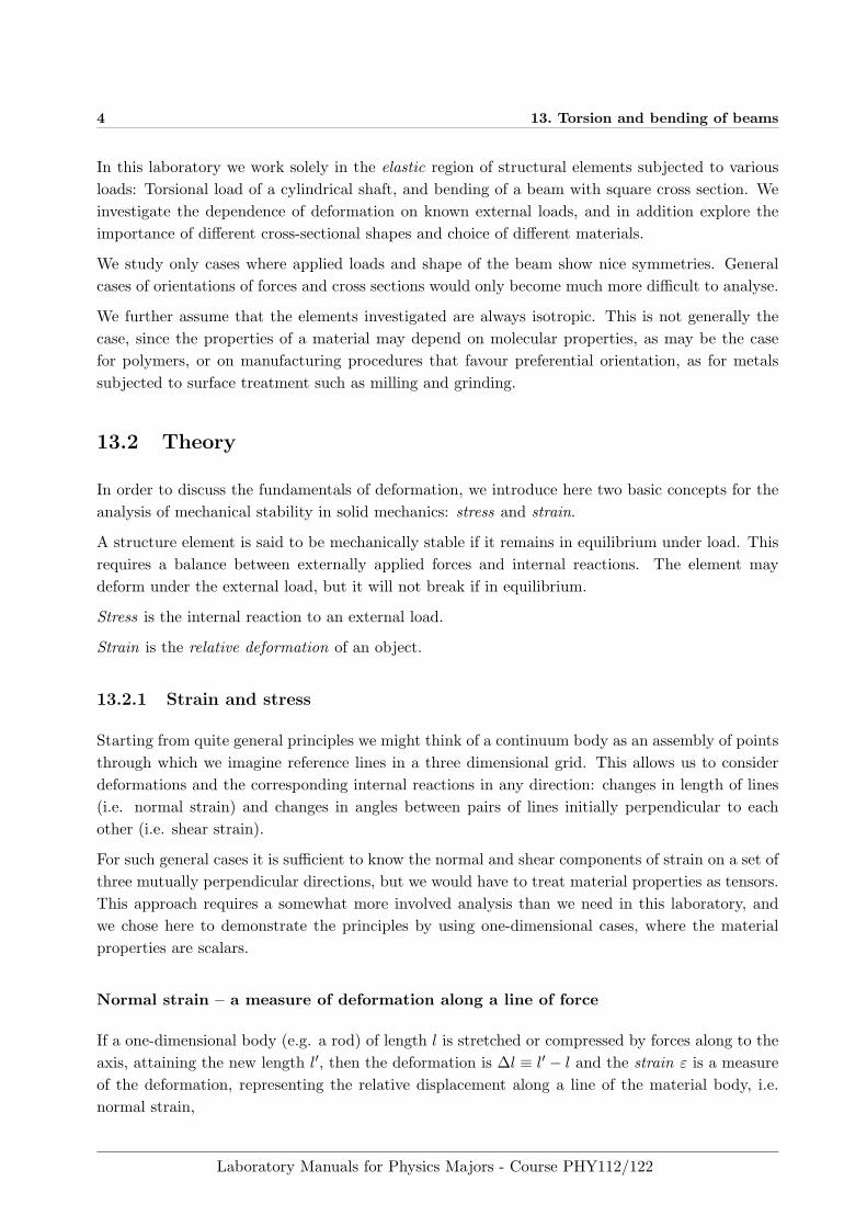
Figure 13.3: Schematic diagram of shearing of a cube with surface area A.
Using the result above we may write:E =
σ
ε(13.8)
The modulus of elasticity is a materials constant of great importance in solid mechanics and me-chanical design.
We may define other elastic moduli, each describing in different ways the tendency of an object todeform elastically (i.e., non-permanently) when a load is applied.
If a cube is subjected to forces parallel to one of its faces, as shown in Fig. 13.3, the amountof shearing may be defined using a certain angle δ as in the figure. Any surface cut parallel tothe faces where the forces act (horizontal cuts in the figure) experiences a shear stress τ = F/A,whereas the normal stress is zero. The shear stress is actually a tensor entity, but remaining withour one-dimensional examples, we abstain from developing this further. If the external forces Fare not too large, the shearing angle δ is proportional to the magnitude of the force, and thereforeto the shear stress τ . The constant of proportionality is the shear modulus or modulus of rigidity,commonly designated with symbols G or µ.
For shear stress the equivalent Hooke’s law expression becomes
τ = Gδ (13.9)
We may take as a formal definition of shear modulus:
G ≡ τ
δ(13.10)
The shear modulus (or modulus of rigidity) G describes an object’s tendency to shear (the defor-mation of shape at constant volume) when acted upon by opposing forces that are not in-line; it isdefined as shear stress over shear strain. The shear modulus is part of the derivation of viscosity.
Just as the modulus of elasticity, G is an important materials constant, either tabulated or madedirectly available in CAD software. The generic definition above again gives this parameter asshear stress over shear strain. The shear modulus has important implications in the derivation ofa theory of viscosity of fluids.
For the sake of completeness, we finally mention the bulk modulus K, which describes volumetricelasticity, or the tendency of an object’s volume to deform under pressure; it is defined as volumetric
Laboratory Manuals for Physics Majors - Course PHY112/122
13.2. THEORY 9
stress over volumetric strain, and is the inverse of the compressibility, another important material’sproperty. As an example, the bulk modulus is of use for comparison of actual data with computersimulations of molecular processes (molecular dynamic, MD). It is a generalisation of Young’smodulus to three dimensions.
b) Torsion of a cylindrical rod
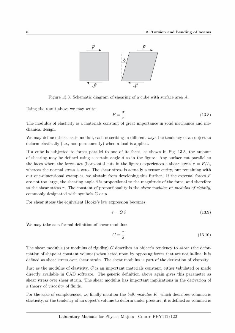
A cylindrical rod with length l and radius R is fixed and rigidly supported at one end, and maybe loaded at the other end with an axial torque, as shown in Fig. 13.4. If the rod under load is inequilibrium, the external torque is balanced internal by the shear stress. The shear stress may beseen as acting in each imaginary perpendicular cut with a torque equal but opposite to the externaltorque.
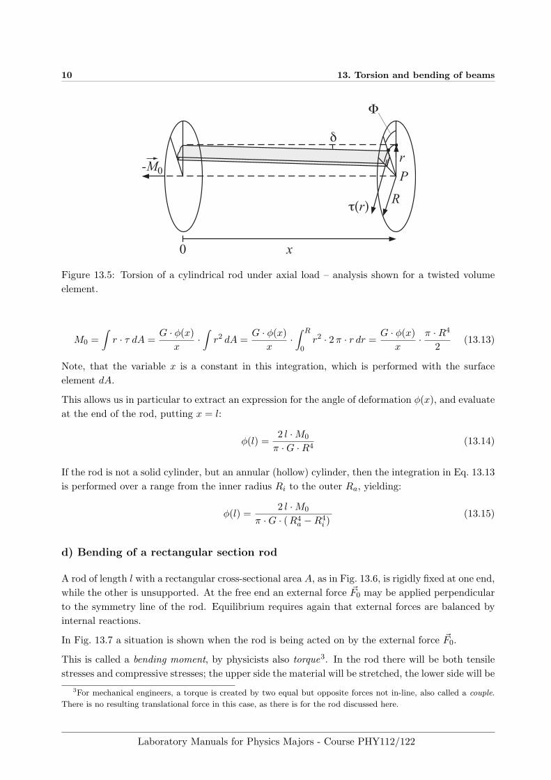
Twisting a rod by applying an external torque makes it respond as in Fig. 13.5. A volume elementis shown, that in the relaxed (unloaded) equilibrium state would be a strip cut from an annularcylinder (cylindrical shell).
As the external axial torque M0 twists the rod, a section perpendicular to the axis at a distance xfrom the end rotates through the angle φ(x). With the chosen geometry the angle increases alongthe rod with position x. If we would draw a straight line on the surface of the relaxed rod, parallelto the axis, then this line would be a helix (screw shaped line), making everywhere an angle δ tothe undisturbed straight line.
From a simple geometric consideration, we may write, using the approximation tan δ ≈ δ, valid forsmall angles:
x · δ = r · φ (13.11)
The volume element shown in Fig. 13.5 is sheared through the angle δ, and the corresponding shearstress τ acts at the end surface. The situation is equivalent to that for the cube in Fig. 13.3.
For not too large a torque Hooke’s law is valid in its shear form
τ = G · δ = G · r · φx
(13.12)
For the volume element in Fig. 13.5 to be in equilibrium, the external torque M0 and the internalreaction τ must be equal. For simplicity we calculate the internal reaction relative to a point P :
-M0 M0
F
-F
0 x l
Rx
Figure 13.4: Torsion of a cylindrical rod – schematic overview.
Laboratory Manuals for Physics Majors - Course PHY112/122
10 13. Torsion and bending of beams
0 x
R
Pr
Φ
δ
τ(r)
-M0
Figure 13.5: Torsion of a cylindrical rod under axial load – analysis shown for a twisted volumeelement.
M0 =∫r · τ dA =
G · φ(x)x
·∫r2 dA =
G · φ(x)x
·∫ R
0r2 · 2π · r dr =
G · φ(x)x
· π ·R4
2(13.13)
Note, that the variable x is a constant in this integration, which is performed with the surfaceelement dA.
This allows us in particular to extract an expression for the angle of deformation φ(x), and evaluateat the end of the rod, putting x = l:
φ(l) =2 l ·M0
π ·G ·R4(13.14)
If the rod is not a solid cylinder, but an annular (hollow) cylinder, then the integration in Eq. 13.13is performed over a range from the inner radius Ri to the outer Ra, yielding:
φ(l) =2 l ·M0
π ·G · (R4a −R4
i )(13.15)
d) Bending of a rectangular section rod
A rod of length l with a rectangular cross-sectional area A, as in Fig. 13.6, is rigidly fixed at one end,while the other is unsupported. At the free end an external force ~F0 may be applied perpendicularto the symmetry line of the rod. Equilibrium requires again that external forces are balanced byinternal reactions.
In Fig. 13.7 a situation is shown when the rod is being acted on by the external force ~F0.
This is called a bending moment, by physicists also torque3. In the rod there will be both tensilestresses and compressive stresses; the upper side the material will be stretched, the lower side will be
3For mechanical engineers, a torque is created by two equal but opposite forces not in-line, also called a couple.
There is no resulting translational force in this case, as there is for the rod discussed here.
Laboratory Manuals for Physics Majors - Course PHY112/122

13.2. THEORY 11
A
F0
ln
F0
Figure 13.6: Rod with rectangular cross section before force is applied.
n
h
xlx h(x)
στ
F0
Figure 13.7: Bending of a rod with rectangular cross section under the action of a perpendicularforce.
compressed. This means that in the rod there must be an un-deformed, ’neutral’ line (or surface),often called the neutral axis, n. A cross section perpendicular to n will remain perpendicularindependent of the bending, as long as the material remains in the elastic region.
Failure in bending will occur when the bending moment is sufficient to induce tensile stresses greaterthan the yield stress of the material, either in extension or compression. Failure because of shearmay occur before failure in bending.
A cross-sectional surface perpendicular to the neutral axis is subject to a constant shear stress τ ,(whereas the normal stress varies because of the bending).
τ =F0
A(13.16)
The external force F0 is thus compensated by stress as long as the rod remains in equilibrium. cfFig. 13.7.
Laboratory Manuals for Physics Majors - Course PHY112/122
12 13. Torsion and bending of beams
A formula for the deformation
Next our purpose is to develop expressions that connect the measurable deformation with theparameters of stress introduced above. Macroscopic equilibrium in particular means that externalforces and moments must be globally balanced. The equation for equilibrium of the moments forthe rod would look like this:
M0 = F · l (13.17)
where M0 is the moment at the point of fixture in the wall.
Since we are not dealing with a rigid mechanics problem, this relation is of little use. We thereforeapply the same reasoning to the part of the rod shaded grey in Fig. 13.7, and separated from therod by an imaginary perpendicular cut at co-ordinate x. By doing so, we are able to introduceinternal stress into the equilibrium equations.
First, we write the global equilibrium for the piece of the rod cut at x:
M(x) = F0 · ( l − x ) (13.18)
This relation is valid for any cut at a position x. The moment M(x) varies with the co-ordinate xand assumes its maximum at x = 0 , i.e. at the position where the rod is rigidly fixed.
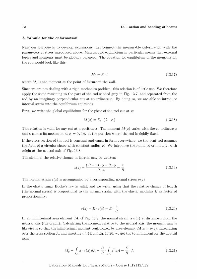
If the cross section of the rod is constant and equal in form everywhere, we the bent rod assumesthe form of a circular shape with constant radius R. We introduce the radial co-ordinate z, withorigin at the neutral axis cf Fig. 13.8.
The strain ε, the relative change in length, may be written:
ε(z) =(R+ z ) · φ−R · φ
R · φ=z
R(13.19)
The normal strain ε(z) is accompanied by a corresponding normal stress σ(z)
In the elastic range Hooke’s law is valid, and we write, using that the relative change of length(the normal stress) is proportional to the normal strain, with the elastic modulus E as factor ofproportionality:
σ(z) = E · ε(z) = E · zR
(13.20)
In an infinitesimal area element dA, cf Fig. 13.8, the normal strain is σ(z) at distance z from theneutral axis (the origin). Calculating the moment relative to the neutral axis, the moment arm islikewise z, so that the infinitesimal moment contributed by area element dA is z ·σ(z). Integratingover the cross section A, and inserting σ(z) from Eq. 13.20, we get the total moment for the neutralaxis:
M ′0 =∫
Az · σ(z) dA =
E
R·∫
Az2 dA =
E
R· Iz (13.21)
Laboratory Manuals for Physics Majors - Course PHY112/122

13.2. THEORY 13
z
dA
σ(z) dAσ(-z)σ(z)
ϕ
R
n0
Figure 13.8: Bending a rectangular rod – detail.
Appearing in this expression is the so called area moment of inertia or second moment of inertiaIz =
∫A z
2 dA, (sometimes the second moment of area), making a short digression due here.
The resistance of a beam to bending and deflection depends not only on the load but also on thegeometry of the beam’s cross-section, or more precisely, how area is distributed in the cross section.
A rectangular beam of width b and thickness d in the plane of bending has the area moment:
Iz =b · d3
12(13.22)
A beam with I-shaped cross section will have a slightly smaller area moment. We might think of itas cut out of the rectangular beam, its profile fitting inside. The much smaller mass, however, inthe end gives a stiffer and lighter structure, which is a consequence of the relatively large area farfrom the neutral line. For this reason, beams with higher area moments of inertia, such as I-beams,are often preferred in building construction, as opposed to other beams with the same area4.
Despite the apparent likeness, the second moment of area is not at all the same thing as the momentof inertia, as used, i.e, in Newtons’s second law for calculating angular acceleration. As a wordof warning, It is not uncommon to refer to the second moment of area as the moment of inertiaand use the same symbol I for both. It is usually clear from the context, though, if accelerationalor bending moment of inertia is meant, and it becomes obvious from the units: second momentof area has unit length to the fourth power, whereas a moment of inertia has the unit mass timeslength squared.
4For the case of torsional load, the polar moment of inertia, characterises an object’s ability to resist torsion.
Laboratory Manuals for Physics Majors - Course PHY112/122
14 13. Torsion and bending of beams
In order that the structure element be in equilibrium, we require that
M ′0(x) = M0(x) equivalent toE
R(x)· Iz = F0 · ( l − x ) (13.23)
For large bending radii R, i.e. a small deformation, we approximately have:
1R
=d2h
dx2(13.24)
with h(l) the deflection from the centre line at the free end, cf Fig. 13.7, and h(x) the deflection atco-ordinate x. Inserting in Eq. 13.23 yields a differential equation
d2h
dx2=
F0
E · Iz· ( l − x ) (13.25)
which is twice integrated to give:
h(x) =F0
E · Iz·(l · x2
2− x3
6
)+ C1 · x+ C2 (13.26)
The two integration constants may be determined from the boundary conditions at x = 0 wherethe beam is fixed. Here we have h(0) = 0 and dh
dx = 0, from which follows C1 = C2 = 0. Themaximum deflection at the end (x = l) is then
h(l) =F0
E · Iz·(l3
2− l3
6
)=
F0 · l3
3E · Iz(13.27)
Laboratory Manuals for Physics Majors - Course PHY112/122
13.3. EXPERIMENTAL 15
13.3 Experimental
In this laboratory we use the relations 13.14 for an external torque and the corresponding torsionangle, and 13.27 for an external force and the deflection. Our purpose is to determine the elasticconstants for the materials used.
a) Torsion of a cylindrical rod
In the first part of the experiments, different cylindrical rods are loaded with external torque andthe torsion angle φ = φ(l) measured at the end x = l of the rod. The torsion angle may beread directly from an angular scale. In addition, provision is made for the use of a laser beamto determine the deflection to calculate the angle. The assistant explains the use of the secondmethod. Try both methods and compare the results. Discuss with the assistant pros and cons ofthe two methods.
The external moment M0 is produced with the aid of masses m attached to the periphery of a diskwith radius Rs, fastened to the end of the rod. Then M0 = m · g ·Rs and Gl. 13.14 gives us:
φ =2 l · g ·Rs
π ·G ·R4·m (13.28)
The masses are chosen for each rod so that the torsion angle φ never increases beyond 15◦ and thedeformation remains linear elastic.
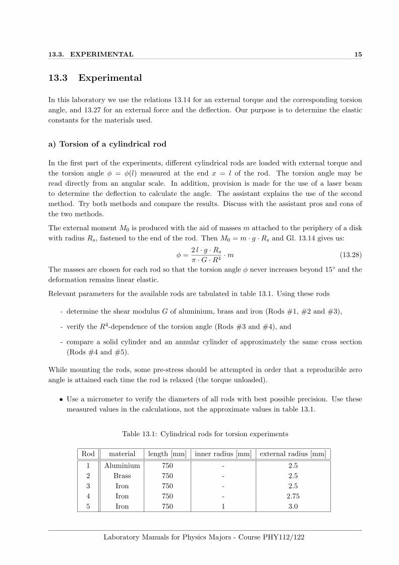
Relevant parameters for the available rods are tabulated in table 13.1. Using these rods
- determine the shear modulus G of aluminium, brass and iron (Rods #1, #2 and #3),
- verify the R4-dependence of the torsion angle (Rods #3 and #4), and
- compare a solid cylinder and an annular cylinder of approximately the same cross section(Rods #4 and #5).
While mounting the rods, some pre-stress should be attempted in order that a reproducible zeroangle is attained each time the rod is relaxed (the torque unloaded).
• Use a micrometer to verify the diameters of all rods with best possible precision. Use thesemeasured values in the calculations, not the approximate values in table 13.1.
Table 13.1: Cylindrical rods for torsion experiments
Rod material length [mm] inner radius [mm] external radius [mm]
1 Aluminium 750 - 2.52 Brass 750 - 2.53 Iron 750 - 2.54 Iron 750 - 2.755 Iron 750 1 3.0
Laboratory Manuals for Physics Majors - Course PHY112/122

16 13. Torsion and bending of beams
Determination of the shear modulus of aluminium, brass and iron
• Mount aluminium rod #1, allowing for the required pre-stress.
• Load the rod with a torque consecutively using weights of mass 0.25 kg, 0.5 kg and 0.75 kg,and measure the corresponding torsion angle φ at the end of the rod.
• Draw a diagram of angle φ as function of mass m. Draw the best fitting straight line forthe points representing the measurements. Note, that the line not necessarily have to passthrough the origin (why?). Determine G from the slope. Estimate the error in G.
• Repeat the measurement with rod #2, using masses 0.25 kg, 0.5 kg, 0.75 kg and 1.0 kg.
• Repeat the measurement with rod #3, using masses 0.5 kg, 1.0 kg, 1.5 kg, and 2.0 kg.
Verifying the R4-dependence of the torsion angle
• Mount the thin iron rod #3, allowing for pre-stress.
• Load the rod with a torque using masses 0.25 kg and 2.0 kg and measure the torsion angle φat the end of the rod.
• Repeat the experiment for the thicker iron rod #4. Use the same masses as for rod #3.
• Compare the torsion angle for both rods for equal torques. Verify that
φ4
φ3=R4
3
R44
(13.29)
Comparison of a solid cylinder shape and annular cylinder shape
• Mount the solid cylinder shaped rod #4 with pre-stress applied as before.
• Load the rod with a torque, using masses 0.25 kg and 2.5 kg. Measure the torsion angle φ atthe end of the rod.
• Repeat the measurement for the annular cylinder shaped rod #5. Use the same masses asfor the solid cylinder shaped rod #4.
• Compare the torsion angle of both rods at equal torsional load. Verify that:
φ4
φ5=R4
5,a −R45,i
R44
(13.30)
• Calculate the cross sectional area of both rods from the measurements and discuss the ratioof mass to stiffness.
Laboratory Manuals for Physics Majors - Course PHY112/122
13.3. EXPERIMENTAL 17
StabBalken Wasserwaage
Mikrometer-schraube
h
F0
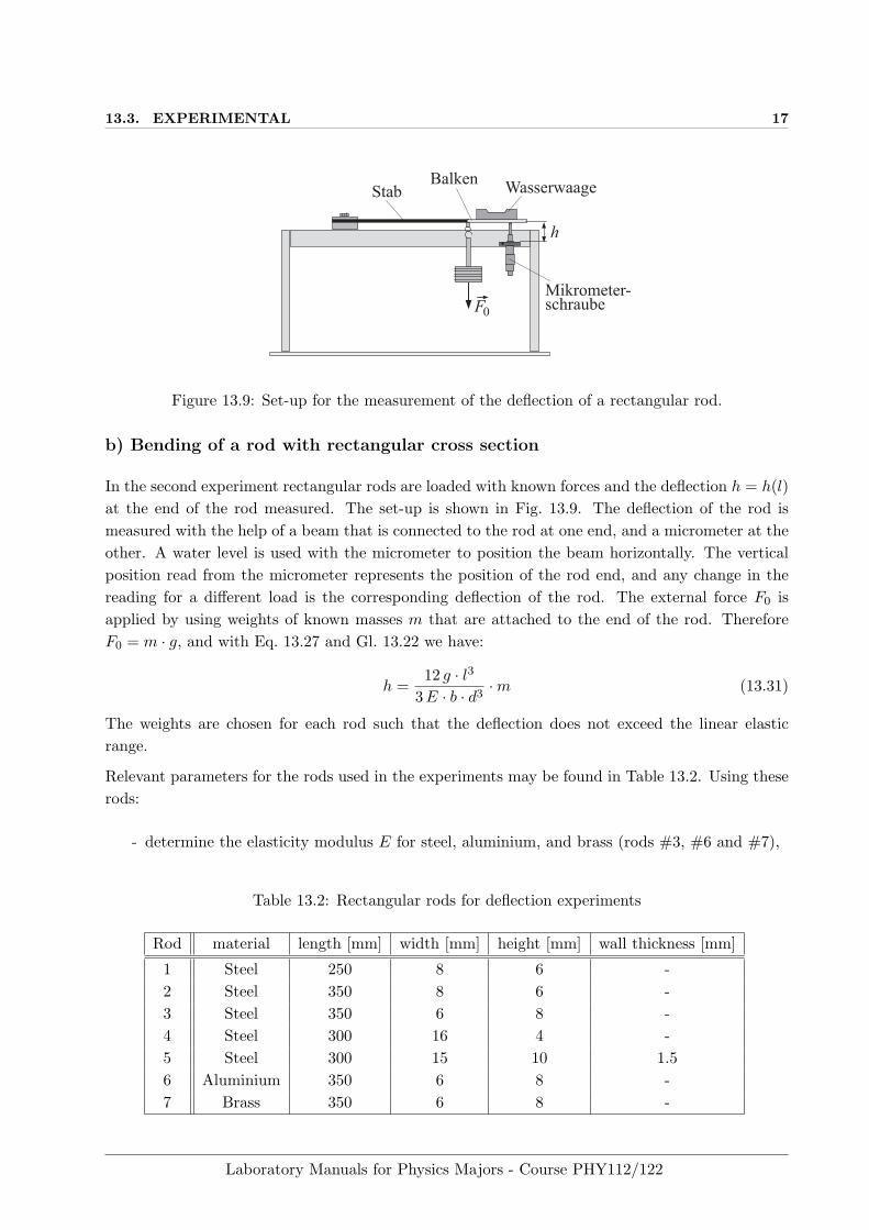
Figure 13.9: Set-up for the measurement of the deflection of a rectangular rod.
b) Bending of a rod with rectangular cross section
In the second experiment rectangular rods are loaded with known forces and the deflection h = h(l)at the end of the rod measured. The set-up is shown in Fig. 13.9. The deflection of the rod ismeasured with the help of a beam that is connected to the rod at one end, and a micrometer at theother. A water level is used with the micrometer to position the beam horizontally. The verticalposition read from the micrometer represents the position of the rod end, and any change in thereading for a different load is the corresponding deflection of the rod. The external force F0 isapplied by using weights of known masses m that are attached to the end of the rod. ThereforeF0 = m · g, and with Eq. 13.27 and Gl. 13.22 we have:
h =12 g · l3
3E · b · d3·m (13.31)
The weights are chosen for each rod such that the deflection does not exceed the linear elasticrange.
Relevant parameters for the rods used in the experiments may be found in Table 13.2. Using theserods:
- determine the elasticity modulus E for steel, aluminium, and brass (rods #3, #6 and #7),
Table 13.2: Rectangular rods for deflection experiments
Rod material length [mm] width [mm] height [mm] wall thickness [mm]
1 Steel 250 8 6 -2 Steel 350 8 6 -3 Steel 350 6 8 -4 Steel 300 16 4 -5 Steel 300 15 10 1.56 Aluminium 350 6 8 -7 Brass 350 6 8 -
Laboratory Manuals for Physics Majors - Course PHY112/122

18 13. Torsion and bending of beams
- verify the l3-dependence of the deflection (rods #1 und #2).
- compare deflections for rods with different cross-sectional shapes but approximately equalarea. (Rods #2, #3, #4 and #5).
For all measurements pay attention to the following:
• Using a micrometer, measure the dimensions of all rods
• With the rods mounted, measure the length l of all rods from the point of fixture to the freeend.
• For all calculations, use measured values of the parameters, not the approximate values inTable 13.1.
Determination of the elastic modulus of steel, aluminium and brass
• Mount rod #3 (steel) in the measurement set-up without a load. Adjust the micrometerusing the water level and determine the reference position.
• Load the rod consecutively with weights of masses 0.5 kg, 1.0 kg, 1.5 kg und 2.0 kg. For eachload read the position indicated by the beam adjusted with the micrometer to horizontalposition with the water level. Calculate the deflection from the reference position.
• Draw a diagram of the deflection h as function of mass m. Fit a best straight line to theexperimental points, and determine the elasticity modulus E from the slope. Estimate theerror of E.
• Repeat the measurement with rod #6 (aluminium), using masses 0.25 kg, 0.5 kg, 0.75 kg,1.0 kg and 1.25 kg.
• Repeat the measurement with rod #7 (aluminium), using masses 0.25 kg, 0.5 kg, 0.75 kg,1.0 kg, 1.25 kg and 1.5 kg.
Verification of the l3-dependence of the deflection
• Mount the short rod #1 (steel) and read the position without external load.
• Load the mounted rod with a weight of mass 1.0 kg. Measure the position and calculate thedeflection h of the end.
• Repeat the measurement for the longer rod #2 (steel). For the calculation, use the samemass as for rod #1.
• Compare the deflections of the two rods and verify that for equal load
h2
h1=l32l31
(13.32)
Laboratory Manuals for Physics Majors - Course PHY112/122
13.3. EXPERIMENTAL 19
Dependence of the deflection on the area moment of inertia
• Mount the flat rod #2 (steel) and measure the reference position without external load asbefore.
• Load the rod with a weight of mass 1.5 kg and measure the position and calculate the deflectionh at the end of the rod.
• Repeat the measurement for rods #3, #4 and #5. Use the mass of rod #2 in the calculations.
• Calculate the area moment of inertia of the four rods according to Eq. 13.22 (consider thearea moment of inertia for a hollow rectangular cross section, and devise a method in analogywith Eq. 13.22 for its determination. Verify that for equal load the ratio of the deflections forthe two possible orientations i and j (’portrait’ and ’landscape’), that the following relationholds:
hi
hj=Iz,j
Iz,i(13.33)
• Calculate the cross section of the four rods and discuss the influence of the cross-sectionalshape and the ratio of mass of the rod to the stiffness.
Laboratory Manuals for Physics Majors - Course PHY112/122