structure simulation and analysis of metal-cutting tool
TRANSCRIPT

Structure simulation and analysis of metal-cutting tool simulation results
Anna Morozova Manager of innovation activities
Bryansk State Technical University, 7, 50 let Oktyabrya Blvd., Bryansk, Russia, 241035
e-mail: [email protected]
Boris Mokritskii Professor of the chair "Technology
of mechanical engineering" Komsomolsk-na-Amure State
University, 27, Lenin Av., Komsomolsk-na-Amure, Russia, 681013
e-mail: [email protected]
Vladislav Vereshchagin Senior lecturer of the department "Information,
service and general technical disciplines" Novosibirsk State Pedagogical University,
28, Viluiskaya, Novosibirsk, 630028 Novosibirsk, Russia
e-mail: [email protected]
Abstract— A continuous change of physical and mechanical characteristics and operational properties of functional and structural materials demands a corresponding adjustment of the cutting tool material for machining. The adjustment involves the development of a new tool material and sometimes a new design tool. These two directions of the improvement of metal-cutting tools have a lot of solutions. A look through these options by trial and error is expensive and laborious. Of course, that there are accepted trends in the choice of a rational variant, but they are not justified scientifically and are associated with the experience of the developer. In this situation, it is desirable to simulate the processing of the workpiece with a tool to identify the most preferred solutions for the design and material of the tool. The possibility of using the ANSYS software environment (standard module Workbench Explicit Dynamics) for such a choice of the preferred variants of the design and material of the tool is considered.
Keywords— virtual simulation; end-milling cutters
I. INTRODUCTION
Physical and mathematical models allow optimizing the process of machining with a blade tool. Moreover, a continuous change of physical and mechanical characteristics and operational properties of functional and structural materials being developed requires the appropriate adjustment of the properties of tool materials for the processing of workpieces. The correction involves the development of a new tool material, and sometimes a new tool design. These two directions of the improvement of metal-cutting tools have a lot of solutions. To go over these solutions by trial and error is expensive and laborious. Of course, there are accepted trends of a rational choice, but they are not scientifically justified and
involve the presence of the relevant experience of the developer.
In this situation, it is desirable to simulate the processing of the workpiece with a tool to identify the most preferred solutions for the design and material of the tool.
The possibility of using the ANSYS software environment (standard module Workbench Explicit Dynamics) for such a choice of the preferred variants of the design and material of the tool is considered.
II. MATERIALS AND METHODS
The possibility of limiting the traditional use of monolithic (whole) solid hard alloy end-milling cutters through the use of compound ones (the cutting part is of a tool hard alloy, the shank is of a different material). As an example, the instrumental hard alloy ВК8 , which also includs alloys with different coatings, is considered. The materials from which the workpiece parts are made are the structural steel grade 30ХГСА and hard-to-cut special materials (the stainless steel 12Х15Н5АМ3 and the titanium alloy ВT20).
The CAE system SolidWorks 2016 is used as an environment of virtual simulation , and the calculation of VAT and the deformation of the cutter during the machining process of the workpiece was made using the Simulation module of finite element analysis included into the SolidWorks 16.
The choice of these software products is explained by the fact that they are publicly available and allow to calculate VAT, as well as deformations with the acceptable accuracy for our task.
International Conference on Aviamechanical Engineering and Transport (AviaENT 2018)
Copyright © 2018, the Authors. Published by Atlantis Press. This is an open access article under the CC BY-NC license (http://creativecommons.org/licenses/by-nc/4.0/).
Advances in Engineering Research, volume 158
286

A finite-element model of the cutter was constructed for numerical calculations. To ensure the sufficient accuracy of computer simulation it was broken into more than 100 thousand elements. The results of breaking the cutter model into finite elements are shown in Fig. 1.
Fig. 1. The cutter model with a finite element grid.
The simulation is based on the following calculation scheme of the cutter body deformation, Fig. 2.
Fig. 2. A scheme of formation of deviation B from the vertical position of the wall of the processed groove under the action of the radial component of the cutting force P1: 1 - cutter shank; 2 - hard alloy cutting portion of the cutter; 3 - clamping device of the machine-tool; 4 - treated surface of workpiece groove 5 - workpiece
The following tool parameters are conditionally accepted for the numerical simulation of stress fields and magnitudes of deformation by the finite element method: overall length of cutter L = 90 - 220 mm; length of the cutting portion l = 40mm; milling cutter diameter d = 12 – 16 mm; material of the cutting portion of the cutter – harh alloy brand ВК8; shank material – may be different ( materials 40X, Р18, Т30К4 are considered). The cutting force during the simulation was 3000
N. Physical and mechanical characteristics of the material of the cutter shank are tabulated in table 1.
TABLE I. PHYSICAL AND MECHANICAL PROPERTIES OF THE TOOL MATERIAL
Geometric parameters of the
cutter model
Physical and mechanical properties of the material of the tool: the monolithic
cutter(ВК8), mill compound (ВK8+Р18), mill compound (ВK8+Т30К4),compound
cutter (В Physical and Mechanical Properties of the Tool Material K8+40X)
End-milling cutter diameter 12-16 mm; - angle of inclination of the screw groove-35°; - main angle in plan-90°
Material ВК8
- the modulus of elasticity 550000 n/mm2 - mass density 14.8 g/cm3 - Poisson's ratio-0.2 - the bending strength of 1,700 MPa - the ultimate compressive strength of 4000 MPa
Material Р18
- the modulus of elasticity of 250,000 n/mm2 - mass density 8.8 g/cm3 - Poisson's ratio-0.25 - the bending strength 3200 MPa - the limit of compressive strength of 4520 MPa
Material Т30К4
- the modulus of elasticity 422000 n/mm2 - mass density of 9.8 g/cm3 - Poisson's ratio-0.21 - the bending strength 1000 MPa - the limit of compressive strength of 3820 MPa
Material 40Х
- the modulus of elasticity 215000 n/mm2 - mass density 7.8 g/cm3 - Poisson's ratio-0.25 - the bending strength of 2400 MPa - the limit of compressive strength of 4300 MPa
According to the results of the simulation the picture of stress distribution in the cutter body is obtained, Fig. 3.
Fig. 3 shows that the highest stresses occur in the area of mounting the cutter in the spindle chuck of the machine-tool.
The results of calculating the values of deformations of the cutter (displacements from the vertical position) at the above stress pattern are shown in Fig. 4.
Fig. 5 shows a histogram of the deformations of cutters which length is 120 mm and the depth of the groove wall is 40 mm. The histogram gives three examples of materials used for shank manufacturing, namely structural steel brand 40X, tool steel brand Р18, non-instrumental hard alloy brand Т30К4.
Advances in Engineering Research, volume 158
287
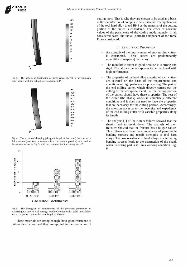
Fig. 3. The pattern of distribution of stress values (MPa) in the composite cutter model with the cutting force component P1
Fig. 4. The picture of changing (along the length of the cutter) the sizes of its deformations (mm) (the movements from the vertical position) as a result of the stresses shown in Fig. 3, with the component of the cutting force P1.
Fig. 5. The histogram of comparisons of the precision parameters of processing the groove wall having a depth of 40 mm with a solid (monolithic) and a composite cutter with a total length of 120 mm
These materials are strong enough, have good resistance to fatigue destruction, and they are applied in the production of
cutting tools. That is why they are chosen to be used as a basis in the manufacture of composite cutter shanks. The application of the tool hard alloy brand ВK8 as the material of the cutting portion of the cutter is considered. The cases of constant values of the parameters of the cutting mode, namely, in all considered cases, the radial (normal) component of the force P1 are considered.
III. RESULTS AND DISCUSSION
• An example of the improvement of end- milling cutters is considered. These cutters are predominantly monolithic (one-piece) hard alloy.
• The monolithic cutter is good because it is strong and rigid. This allows the workpieces to be machined with high performance.
• The properties of the hard alloy material of such cutters are selected on the basis of the requirements and conditions of high performance processing. The part of the end-milling cutter, which directly carries out the cutting of the workpiece metal, i.e. the cutting portion of the cutter, should have these properties. The rest of the cutter (the shank) works in completely different conditions and it does not need to have the properties that are necessary for the cutting portion. Accordingly, the question arises as to the necessity and expediency of the end-milling cutter with variable properties along its length.
• The analysis [1] of the cutters failures showed that the shanks tend to break down. The analysis of their fractures showed that the fracture has a fatigue nature. This follows also from the comparisons of permissible bending stresses and tensile strengths of tool hard alloys. The low resistance of hard alloys to alternating bending stresses leads to the destruction of the shank when its cutting part is still in a working condition, Fig. 6.
Advances in Engineering Research, volume 158
288

Fig. 6. The illustration of falures of solid end hard alloy tools during the machining of workpieces of parts for their application in aviation A – a chip of the cutting portion of the cutter; B – a chip of the shank at the attachment of the cutter in the chuck; C – chipping of cutting edges; D – a complete destruction of the cutter; F - distribution of cutterls by the type of failure.
The study was carried out at two stages: at the first stage, the design of the end mill was optimized from the standpoint of improving the efficiency of its shank by using the materials other than the material of the cutting portion of the shank; at the second stage, the tool material of the cutter [2] was optimized (architecturized) from the standpoint of improving its performance (the period of wear resistance) due to the targeted choice of coating on the hard alloy substrate. At both stages, computer simulation was used as a tool to select the competitive optimal solutions.
When choosing the design of the cutter [3, 4] the value of the cutting force F was used as an input parameter in the simulation.The processing error (the deviation in the wall of the processed groove) arising from the deflection of the cutter body under the influence of cutting force F was used as an optimization parameter.
Fig. 7 shows some results of the use of different materials (the structural steel grade 40X, the high-speed steel grade P18, the hard alloy brand T30K4) for the cutter shank (the diameter is 16 mm, the cutting length is 40 mm and it is made of the hard alloy brand ВK8, the shank and the cutting part areconnected by soldering). Such cutters are conventionally called composite.
Fig. 7. The histogram of the precision parameters of processing the groove wall 5 mm long, with a one-piece (monolithic) and a composite cutter with a total length of 120 mm.
Fig. 2 shows that the measurement error (deviation) is in the range from 0.0018 mm to 0.006 mm for all the milling cutters being considered, which is quite acceptable for the parts for engineering purposes, including the parts for aeronautical purposes. The smallest difference in the processing errors for monolithic and composite cutters was found in the shank made of Т30К4, it is in the range of 15%. In the case of of application of this material the effect of forcing the processing modes (the cutting force F) on the accuracy parameters, Fig. 8. is studied.
It is seen that the deviation B for any version of the cutter does not exceed 0.06 mm and the dependence has a linear character, which fits into the general notions of strength of materials and material study.
Fig. 8. The graph of the dependence of the deflection B in the groove wall from the cutting force F.
With deeper grooves and a greater overall length of the cutter the range varies, but there is still an area of rational use of composite cutters.
The experimental verification of the data obtained confirmed the results of computer simulation. It allowed to reduce to 20 times the time spent on the choice of the cutter design. The chosen cutter design allows to reduce up to 3 times the consumption of tool hard alloy and to eliminate the
Advances in Engineering Research, volume 158
289

shank breakages (which additionally saves the consumption of tool hard alloy up to 5 times).
The second stage of the study is made for a limited number of substrate coatings ВK8. Simple single-layer nitride coatings of titanium nitride TiN type, complex single-layer coatings of alunotify nitride type (TiAl)N, multilayer coatings of Ti + TiN +(TiAl)N and Ti+TiN+(TiAlCr)N types with different coating thickness are used.
They are selected not only in order to increase the efficiency of the tool as its period of wear resistance is before reaching the maximum permissible value of the cutter teeth wear, but also from the standpoint of the accompanying effects [5, 6, 7], namely the reduction of the friction coefficient [8, 9, 10], the changes of the heat balance in the cutting system [11, 12], the reduction of the total stress in the tool material.
Fig. 4 shows the trend of changing the period of durability of monolithic (highlighted in black) and composite end cutters,which substrate (base) is made of the tool hard alloy brand ВК8 in the processing of billets made of the structural steel 30ХГСА and specialized difficult-to-cut materials (the stainless steel 12Х15Н5АМ3 and the titanium alloy ВТ20).
Fig. 9. The graph of the dependence of the deflection B in the groove wall from the value F.
An example of the composite cutter, designed using the described methodology, is shown in Fig. 10A. An example of its application in processing is shown in Fig.10B, and an example of the processed top and front surfaces of the workpiece, made of an aluminum alloy is shown in Fig. 11.
Fig. 10. The results of the experimental testing of composite cutters: A - the general view of the cutter with a diameter of 16 mm; B –the treated surface of the workpiece with the hardness of HRC 6161.
Fig. 11. The result of the experimental testing of the functionality of composite milling cutters is the treated upper and the front surfaces of the workpiece, made of aluminum alloy.
The data obtained do not contradict the general concepts [9 - 12] and show that only by the optimized choice of coating the performance of cutters can be improved up to 20%. The pilot test confirmed the findings. The computer simulation has reduced the time spent on the selection of competitive coatings up to 20 times.
The study of the treated surfaces showed that manufacturing errors are within acceptable limits. The cost of manufacturing composite cutters is less than the cost of manufacturing monolithic cutters, in particular the cost of soldering the shant with a low temperature solder and the cutting portion does not exceed 2% of the cost of the cutter.
The proposed design methodology of cutters does not set the problem of the exclusion of monolithic cutters. It makes it possible to distinguish between the application of composite and monolithic cutters: the higher the precision requirements for machining, the more rational is the use of monolithic
Advances in Engineering Research, volume 158
290

cutters, in other cases, and this is the overwhelming area of application of end-milling cutters, and the use of composite cutters is more rational.
IV. CONCLUSION
The application of computer simulation using ANSYS software environment based on the finite element method allowed one:
• to reduce to 20 times the time spent on the choice of the optimum (monolithic or composite) design of the end cutter;
• to identify the most efficient configurations of the liner composite cutters;
• to reduce consumption of tool hard alloy 3 times at the expense of manufacturing shanks from not tool materials and 5 times - at the expense of manufacturing shanks from the materials possessing the increased resistance to destruction at alternating cyclic loading;
• to reduce to 20 times the time spent on the selection of competitive coatings on hard alloy tool material.
References
[1] B.Y. Mokritskii, A.V. Morozova, and Т.I. Usova, “Results in Composite
Hard-alloy and Mill Design Based on Simulation of Their Operation Conditions,” Procedia Engineering vol. 206, pp.1093–1098, 2017.
[2] B.Y. Mokritskii, A.A. Vereschaka, A.S. Vereschaka, A.D. Batako, and O.K. Hojaev, “Development and research of nanostructured multilayer composite coatings for tungsten-free carbides with extended area of
technological applications,” International Journal of Advanced Manufacturing Technology, vol. 15, pp. 1-9, 2016.
[3] Ch. Shet, and X. Deng, “Finite element analysis of the orthogonal metal cutting process,” Journal of Materials Processing Technology, vol. 105, pp. 95-109, 2000.
[4] Z. Komanduri, B. Hou, “Thermal modeling of the metal cutting process”. Part III: “Temperature rise distribution due to the combined effects of shear plane heat source and the tool-chip interface frictional heat source,” International Journal of Mechanical Sciences, vol. 43, pp. 89–107, 2001.
[5] W. Grzesik, “Determination of temperature distribution in the cutting zone using hybrid analytical-FEM technique”. Int. J. Mach. Tools Manuf. vol.46, pp. 651–658, 2006.
[6] S. Atlati, B. Haddag, M. Nouari, and M. Zenasni, “Thermomechanical modeling of the tool–work material interface in machining and it simplementation using the ABAQUS VUINTER subroutine,” International Journal of Mechanical Sciences, vol. 87, pp. 102–117, 2014.
[7] S. Buchkremera, B. Wub, D. Lunga, S. Münstermannb, F. Klockea, and W. Bleck, “FE-simulation of machining processes with a new material model,” Journal of Materials Processing Technology, vol. 214, pp. 599– 611, 2014.
[8] D. Parle, R.K. Singh, S.S. Joshi, and G.V. Ravikumar, “Modeling of microcrack formation in orthogonal machining,” International Journal of Machine Tools & Manufacture, vol. 80-81, pp. 18–29, 2014.
[9] B. Haddag, M. Nouari, “Tool wear and heat transfer analyses in dry machining based on multi-steps numerical modeling and experimental validation,” Wear, vol. 302(1-2), pp. 1158–1170, 2013.
[10] D. Parle, R.K. Singh, S.S. Joshi, and G.V. Ravikumar, “Modeling of microcrack formation in orthogonal machining,” International Journal of Machine Tools & Manufacture, vol. 80-81, pp. 18–29, 2014.
[11] W. Grzesik, P. Nieslony, “A computational approach to evaluate temperature and heat partition in machining with multilayer coated tools,” International Journal of Machine Tools & Manufacture, vol. 43, pp. 1311–1317, 2003.
[12] W. Grzesik, P. Nieslony, “Physics based modeling of interface temperatures in machining with multiplayer coated tools at moderate cutting speeds,” International Journal of Machine Tools & Manufacture, vol. 44, pp. 889–901, 2004.
Advances in Engineering Research, volume 158
291