simulation of metal cutting process with variable cutting ... · broaching is a machining process...
TRANSCRIPT

Procedia CIRP 1 ( 2012 ) 437 – 442
Available online at www.sciencedirect.com
2212-8271 © 2012 The Authors. Published by Elsevier B.V. Selection and/or peer-review under responsibility of Professor Konrad Wegenerhttp://dx.doi.org/ 10.1016/j.procir.2012.04.078
5th CIRP Conference on High Performance Cutting 2012
Simulation of metal cutting process with variable cutting thickness during broaching
Volker Schulzea, Nikolay Boeva*, Frederik Zangera awbk Institute of Production Science, Karlsruhe Institute of Technology, Germany
* Corresponding author. Tel.: +49-721-608-46316 ; fax: +49-721-608-45004 .E-mail address: [email protected] .
Abstract
With the advancements of different simulation approaches several metal cutting processes have been simulated, investigated and improved. However, very little work has been published in the field of metal cutting with variable cutting thicknesses by means of cutting simulations. This paper presents a 2D cutting simulation approach using the finite element method (FEM), which is applied in order to predict cutting forces, temperatures and chip shapes while broaching. To investigate the influence of varying cutting thicknesses the broaching process is simulated with different constant cutting thicknesses at the beginning (20, 35 μm and 50 μm). © 2012 Published by Elsevier BV. Selection and/or peer-review under responsibility of Prof. Konrad Wegener
Keywords: Cutting; Chip Formation; Finite element method (FEM); Simulation
1. Introduction
Production efficiency and economically optimized metal cutting processes are raising topics. The knowledge about the actual cutting processes and their influences on the machine structure have to be investigated to achieve a better understanding for optimizing the efficiency. There are a lot of different influencing factors for the interaction between processes and machine tools. This paper presents some investigations on vibrations of the machine structure, which occur during broaching. Broaching has simple dynamic properties, because the parts are machined with one linear cut along the surface of the work piece. Therefore, it is possible to observe the influence of vibrations on the surface integrity of the produced work piece.
Because experimental investigations are expensive and take a long time, a 2D cutting simulation model for the prediction of cutting forces, temperatures and chip shapes while broaching has been developed. The vibrations of the machine structure are presented as a motion of the cutting tooth along and against the machined surface of the work piece. Therefore, during the cutting simulation the cutting tooth has also been
moved orthogonally from the perspective of the work piece. As a result the chip thickness varies during the simulation. To investigate the influence of varying cutting thicknesses, which is the main aim of this paper, the broaching process is simulated with different constant cutting thicknesses at the beginning (20, 35 and 50 μm). For setting varying cutting thicknesses two different approaches are implemented: 1) defining a roughness profile on the surface of the work piece, 2) constant immersion of the tool into the work piece during the process, where the inclination angle of the immersion is limited by the clearance angle of the tool. After process forces have reached a stationary level, each cutting thickness was increased by 15 μm with a constant inclination angle of 7.6°. With the new cutting thicknesses the simulations were continued until the cutting forces reached constant values again. Both of these approaches have been investigated with different cutting velocities vc and are compared to each other as well as to the results of a cutting simulation with a constant cutting thickness. In this paper results of cutting simulations are presented, and finally compared to experimentally obtained data.
© 2012 The Authors. Published by Elsevier B.V. Selection and/or peer-review under responsibility of Professor Konrad WegenerOpen access under CC BY-NC-ND license.
Open access under CC BY-NC-ND license.
Volker Schulze et al. / Procedia CIRP 1 ( 2012 ) 437 – 442 438
2. Broaching
In many published studies the interactions between machine tools and processes are discussed [1, 2, 3, 4], but very little work has been done in the field of broaching by means of cutting simulations [5]. Broaching is a machining process with simple dynamic properties compared to other metal cutting processes. The broach machines the work piece with only one linear motion along the cutting surface.
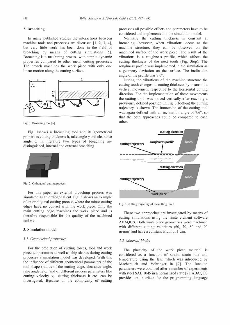
Fig. 1. Broaching tool [6]
Fig. 1shows a broaching tool and its geometrical properties cutting thickness h, rake angle and clearance angle . In literature two types of broaching are distinguished, internal and external broaching.
Fig. 2. Orthogonal cutting process
For this paper an external broaching process was simulated as an orthogonal cut. Fig. 2 shows an example of an orthogonal cutting process where the minor cutting edges have no contact with the work piece. Only the main cutting edge machines the work piece and is therefore responsible for the quality of the machined surface.
3. Simulation model
3.1. Geometrical properties
For the prediction of cutting forces, tool and work piece temperatures as well as chip shapes during cutting processes a simulation model was developed. With this the influence of different geometrical parameters of the tool shape (radius of the cutting edge, clearance angle, rake angle, etc.) and of different process parameters like cutting velocity vc, cutting thickness h etc. can be investigated. Because of the complexity of cutting
processes all possible effects and parameters have to be considered and implemented in the simulation model.
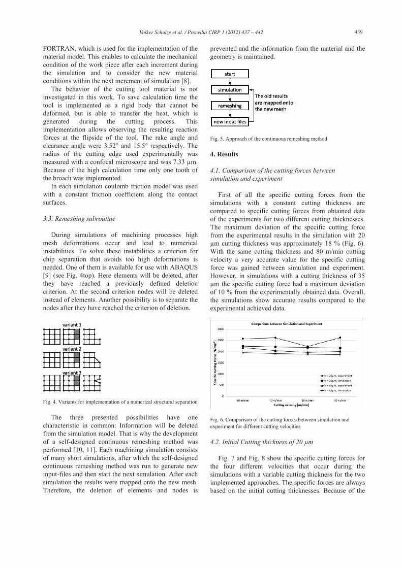
Normally the cutting thickness is constant at broaching, however, when vibrations occur at the machine structure, they can be observed on the machined surface of the work piece. The result of the vibrations is a roughness profile, which affects the cutting thickness of the next tooth (Fig. 3top). The roughness profile was implemented in the simulation as a geometry deviation on the surface. The inclination angle of the profile was 7.6°.
During the vibrations of the machine structure the cutting tooth changes its cutting thickness by means of a vertical movement respective to the horizontal cutting direction. For the implementation of these movements the cutting tooth was moved vertically after reaching a previously defined position. In Fig. 3(bottom) the cutting trajectory is shown. The immersion of the cutting tool was again defined with an inclination angle of 7.6°, so that the both approaches could be compared to each other.
Fig. 3. Cutting trajectory of the cutting tooth
These two approaches are investigated by means of cutting simulations using the finite element software ABAQUS. Both work piece geometries were machined with different cutting velocities (60, 70, 80 and 90 m/min) and have a constant width of 1 μm.
3.2. Material Model
The plasticity of the work piece material is considered as a function of strain, strain rate and temperature using the law, which was introduced by Macherauch and Vöhringer in [7]. The function parameters were obtained after a number of experiments with steel SAE 1045 in a normalized state [7]. ABAQUS provides an interface for the programming language
Volker Schulze et al. / Procedia CIRP 1 ( 2012 ) 437 – 442 439
FORTRAN, which is used for the implementation of the material model. This enables to calculate the mechanical condition of the work piece after each increment during the simulation and to consider the new material conditions within the next increment of simulation [8].
The behavior of the cutting tool material is not investigated in this work. To save calculation time the tool is implemented as a rigid body that cannot be deformed, but is able to transfer the heat, which is generated during the cutting process. This implementation allows observing the resulting reaction forces at the flipside of the tool. The rake angle and clearance angle were 3.52° and 15.5° respectively. The radius of the cutting edge used experimentally was measured with a confocal microscope and was 7.33 μm. Because of the high calculation time only one tooth of the broach was implemented.
In each simulation coulomb friction model was used with a constant friction coefficient along the contact surfaces.
3.3. Remeshing subroutine
During simulations of machining processes high mesh deformations occur and lead to numerical instabilities. To solve these instabilities a criterion for chip separation that avoids too high deformations is needed. One of them is available for use with ABAQUS [9] (see Fig. 4top). Here elements will be deleted, after they have reached a previously defined deletion criterion. At the second criterion nodes will be deleted instead of elements. Another possibility is to separate the nodes after they have reached the criterion of deletion.
Fig. 4. Variants for implementation of a numerical structural separation
The three presented possibilities have one characteristic in common: Information will be deleted from the simulation model. That is why the development of a self-designed continuous remeshing method was performed [10, 11]. Each machining simulation consists of many short simulations, after which the self-designed continuous remeshing method was run to generate new input-files and then start the next simulation. After each simulation the results were mapped onto the new mesh. Therefore, the deletion of elements and nodes is
prevented and the information from the material and the geometry is maintained.
Fig. 5. Approach of the continuous remeshing method
4. Results
4.1. Comparison of the cutting forces between simulation and experiment
First of all the specific cutting forces from the simulations with a constant cutting thickness are compared to specific cutting forces from obtained data of the experiments for two different cutting thicknesses. The maximum deviation of the specific cutting force from the experimental results in the simulation with 20 μm cutting thickness was approximately 18 % (Fig. 6). With the same cutting thickness and 80 m/min cutting velocity a very accurate value for the specific cutting force was gained between simulation and experiment. However, in simulations with a cutting thickness of 35 μm the specific cutting force had a maximum deviation of 10 % from the experimentally obtained data. Overall, the simulations show accurate results compared to the experimental achieved data.
Fig. 6. Comparison of the cutting forces between simulation and experiment for different cutting velocities
4.2. Initial Cutting thickness of 20 μm
Fig. 7 and Fig. 8 show the specific cutting forces for the four different velocities that occur during the simulations with a variable cutting thickness for the two implemented approaches. The specific forces are always based on the initial cutting thicknesses. Because of the
Volker Schulze et al. / Procedia CIRP 1 ( 2012 ) 437 – 442 440
different cutting velocities the increase of the cutting thicknesses started at different times, but at the same cutting length. The initial cutting thickness was 20 μm. When the cutting forces reached an approximately constant value the increase of the cutting thickness occurred at instance. In Fig. 7 the results of the cutting simulation with a roughness profile on the surface of the work piece are presented. Fig. 8 shows the specific cutting forces during the cutting simulation with an immersion of the cutting tooth. The differences between the two approaches will be discussed in the following chapter.
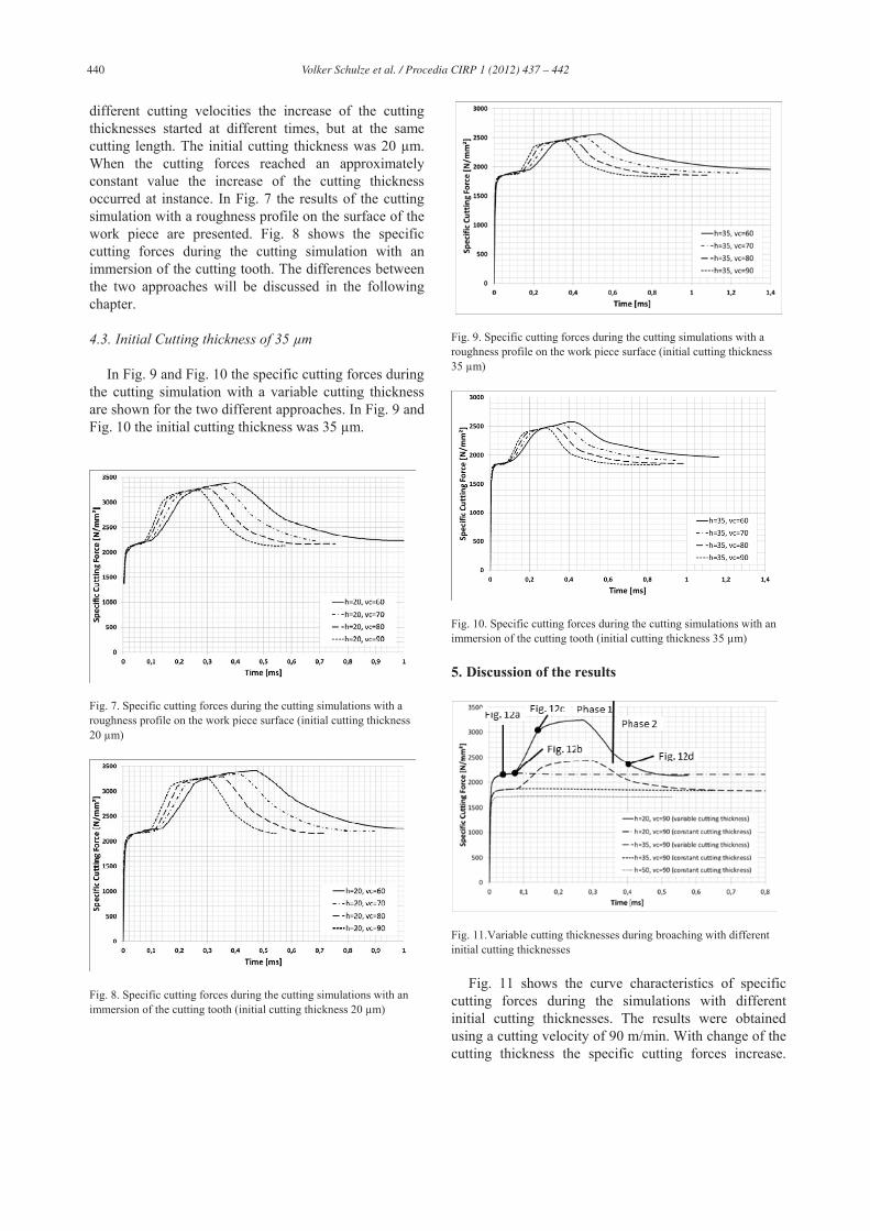
4.3. Initial Cutting thickness of 35 μm
In Fig. 9 and Fig. 10 the specific cutting forces during the cutting simulation with a variable cutting thickness are shown for the two different approaches. In Fig. 9 and Fig. 10 the initial cutting thickness was 35 μm.
Fig. 7. Specific cutting forces during the cutting simulations with a roughness profile on the work piece surface (initial cutting thickness 20 μm)
Fig. 8. Specific cutting forces during the cutting simulations with an immersion of the cutting tooth (initial cutting thickness 20 μm)
Fig. 9. Specific cutting forces during the cutting simulations with a roughness profile on the work piece surface (initial cutting thickness 35 μm)
Fig. 10. Specific cutting forces during the cutting simulations with an immersion of the cutting tooth (initial cutting thickness 35 μm)
5. Discussion of the results
Fig. 11.Variable cutting thicknesses during broaching with different initial cutting thicknesses
Fig. 11 shows the curve characteristics of specific cutting forces during the simulations with different initial cutting thicknesses. The results were obtained using a cutting velocity of 90 m/min. With change of the cutting thickness the specific cutting forces increase.
Volker Schulze et al. / Procedia CIRP 1 ( 2012 ) 437 – 442 441
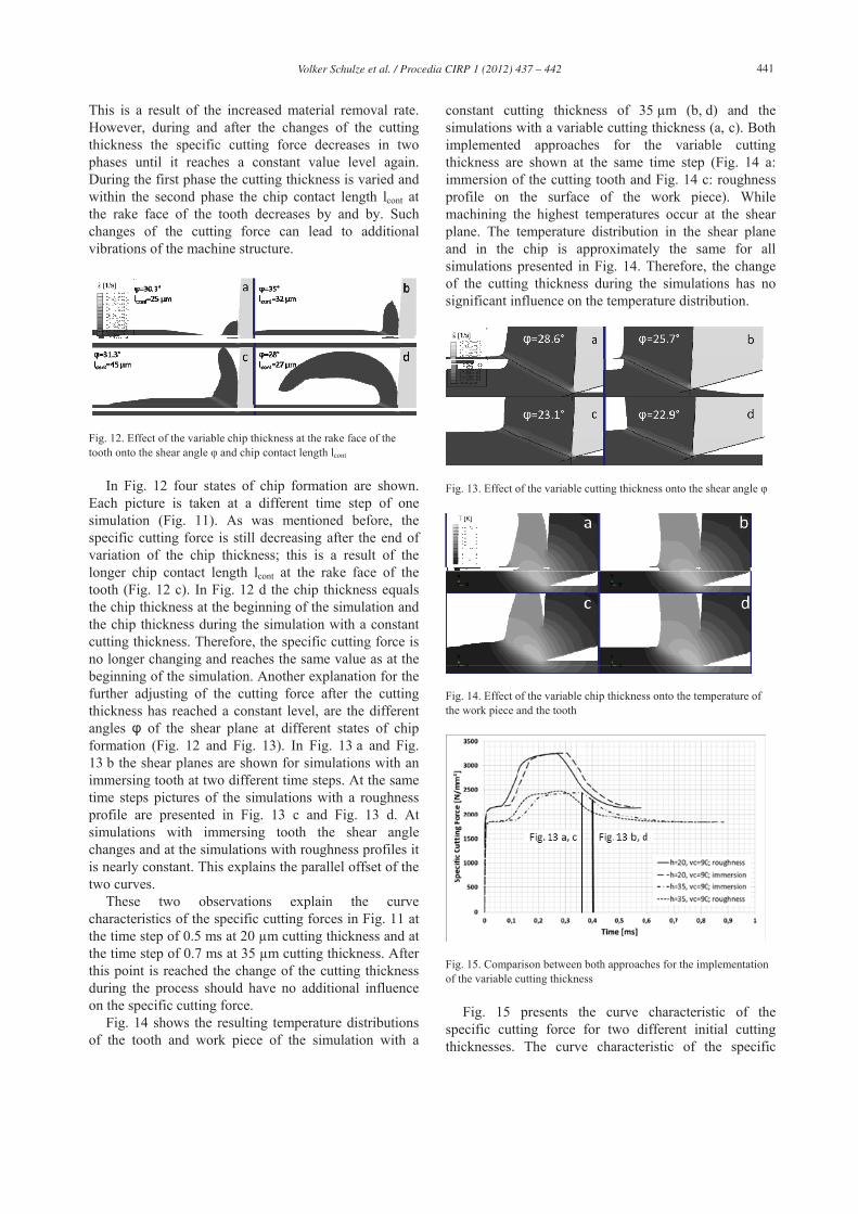
This is a result of the increased material removal rate. However, during and after the changes of the cutting thickness the specific cutting force decreases in two phases until it reaches a constant value level again. During the first phase the cutting thickness is varied and within the second phase the chip contact length lcont at the rake face of the tooth decreases by and by. Such changes of the cutting force can lead to additional vibrations of the machine structure.
Fig. 12. Effect of the variable chip thickness at the rake face of the tooth onto the shear angle and chip contact length lcont
In Fig. 12 four states of chip formation are shown. Each picture is taken at a different time step of one simulation (Fig. 11). As was mentioned before, the specific cutting force is still decreasing after the end of variation of the chip thickness; this is a result of the longer chip contact length lcont at the rake face of the tooth (Fig. 12 c). In Fig. 12 d the chip thickness equals the chip thickness at the beginning of the simulation and the chip thickness during the simulation with a constant cutting thickness. Therefore, the specific cutting force is no longer changing and reaches the same value as at the beginning of the simulation. Another explanation for the further adjusting of the cutting force after the cutting thickness has reached a constant level, are the different angles of the shear plane at different states of chip formation (Fig. 12 and Fig. 13). In Fig. 13 a and Fig. 13 b the shear planes are shown for simulations with an immersing tooth at two different time steps. At the same time steps pictures of the simulations with a roughness profile are presented in Fig. 13 c and Fig. 13 d. At simulations with immersing tooth the shear angle changes and at the simulations with roughness profiles it is nearly constant. This explains the parallel offset of the two curves.
These two observations explain the curve characteristics of the specific cutting forces in Fig. 11 at the time step of 0.5 ms at 20 μm cutting thickness and at the time step of 0.7 ms at 35 μm cutting thickness. After this point is reached the change of the cutting thickness during the process should have no additional influence on the specific cutting force.
Fig. 14 shows the resulting temperature distributions of the tooth and work piece of the simulation with a
constant cutting thickness of 35 μm (b, d) and the simulations with a variable cutting thickness (a, c). Both implemented approaches for the variable cutting thickness are shown at the same time step (Fig. 14 a: immersion of the cutting tooth and Fig. 14 c: roughness profile on the surface of the work piece). While machining the highest temperatures occur at the shear plane. The temperature distribution in the shear plane and in the chip is approximately the same for all simulations presented in Fig. 14. Therefore, the change of the cutting thickness during the simulations has no significant influence on the temperature distribution.
Fig. 13. Effect of the variable cutting thickness onto the shear angle
Fig. 14. Effect of the variable chip thickness onto the temperature of the work piece and the tooth
Fig. 15. Comparison between both approaches for the implementation of the variable cutting thickness
Fig. 15 presents the curve characteristic of the specific cutting force for two different initial cutting thicknesses. The curve characteristic of the specific
Volker Schulze et al. / Procedia CIRP 1 ( 2012 ) 437 – 442 442
cutting force is the same for both approaches. However, if just the curves of one initial cutting thickness are considered for the different approaches, small differences can be seen. The specific cutting forces increase earlier and smoother at the simulations with the roughness on the surface than at the simulations with an immersion, although the beginning of the variable cutting thickness was planned for the same simulation time step (here after 375 μm cutting distance). This effect can be explained with the cutting length: For the simulation with an immersion of the tooth a time (or cutting length) is defined, at which the tooth is immersed into the work piece. When the tool reaches the point of immersion, the increase of the specific cutting force begins. With this approach the increase of the specific cutting force and change of the cutting thickness takes place at the same time. The same time (or cutting length) is defined for the beginning of the roughness profile, where the chip surface reaches the point of increasing cutting thickness earlier, which leads to a smoother change of the cutting thickness. The shear plane and the pre-compression area of the cutting tooth (Fig. 13 c, d) expands due to the increased chip thickness, which causes the cutting force to change before the actual change of the cutting thickness occurs.
6. Conclusions
The influence of a variable cutting thickness caused by vibrations during broaching by means of 2D-cutting simulations was discussed in the presented work. Two different approaches for the realization of the varying cutting thickness during the simulation were introduced and implemented. With these two approaches the broaching process was simulated. The results of the simulations show that the kind of changing the cutting thickness during the process has no influence on the specific cutting force and temperature distribution in the work piece and in the tool, but on the curve characteristics. The simulation with a roughness profile showed a smoother increase and decrease of forces in comparison with the immersion and emersion of the tooth. This was accompanied by a parallel offset of both curves. The differences have been explained with the influence of the shear plane and the contact length between the cutting tooth and the chip. Another conclusion can be drawn out of the curve characteristic during the emersion of the cutting thickness, which implies two different areas: 1) where the change of the cutting thickness occurs; 2) where the chip removes from the rake face. The explanation for this effect is the larger contact length, and the expansion of the shear plane and of the compression area of the cutting tooth. For every cutting thickness a constant contact length in the 2D-cutting simulation was reached. However, during
the change of the cutting thickness the contact zone gets smaller or larger. This leads to a falling or rising value of the specific cutting force. The effects at varying cutting thicknesses, presented in this paper, will be investigated in more detail and presented in a further paper.
Acknowledgement
The authors gratefully acknowledge the support of the German Research Foundation (DFG Deutsche Forschungsgemeinschaft). The authors appreciate the support and the supply of computational time by the Steinbuch Centre for Computing (SCC) at the KIT on the high performance computers ic1 and hc3.
References
[1] Abele E, Bauer J, Friedmann M, Pischan M, Reinl C, von Stryk, O. Einsatz von Robotern in der spanenden Fertigung. Wissenschaftsmagazin forschen; Vol. 1 , 2011 , S. 44-49.
[2] Uhlmann E, Rasper P. Influences on specific cutting forces and their impact on the stability behaviour of milling processes. Production Engineering - Research and Development; Vol. 5 (2), 2011; p. 175-181.
[3] Heisel U, Storchak M, Eberhard P, Gaugele T. Experimental studies for verification of thermal effects in cutting. Production Engineering - Research and Development; Vol. Online First; 2011.
[4] Reinl C, Friedmann M, Bauer J, Pischan M, Abele E, von Stryk O. Model-based off-line compensation of path deviation for industrial robots in milling applications. IEEE/ASME International Conference on Advanced Intelligent Mechatronics (AIM); 2011.
[5] Zhang Y L, Chen W Y. Finite Element Modeling of the Broaching Process of Inconel718, Materials Science Forum; 2012, Vols. 697-698.
[6] Fritz AH und Schulze G. Fertigungstechnik. 8. Auflage, Springer-Verlag Berlin Heidelberg; 2008.
[7] Macherauch E and Vohringer O.Das Verhalten metallischer Werkstoffe unter mechanischer Beanspruchung. Werkstofftechnik 9; Verlag Chemie GmbH, 1978; p. 370-391.
[8] Autenrieth H. Numerische Analyse der Mikrozerspanung am Beispiel von normalisiertem C45E. 2010, Dissertation.
[9] ABAQUS 6.10 manual, Simulia 2010 [10] Autenrieth H, Weber M, Deuchert M, Löhe D, Schulze V,
Gumbsch P, Fleischer J. Influence of process parameters on the specific active and passive forces, subsurface hardening and residual stresses in micro-cutting; Proceedings 2nd Int. Conference on Distortion Engineering, Bremen, 2008, S. 153 - 160
[11] Schulze V, Zanger F. Development of a simulation model to investigate tool wear in Ti-6Al-4V alloy machining, 13th CIRP Conference on Modeling of Machining Operations (CIRP CMMO); 12.-13.05.2011, Sintra, Portugal.