structure-properties of ppe alloy by reactive blending
TRANSCRIPT

ISSN 1349-7308 49http://www.jstage.jst.go.jp/browse/ejsm
Introduction
Recent technological progress in electronics and carindustries inquires for high performance polymers with thehigher heat resistance, the better chemical resistance andthe lower dielectric constant. Poly(2,6-dimethyl phenyleneether) (PPE) may be a nice candidate since it has high heatresistance (the glass transition temperature, Tg�210°C)and low dielectric constant. However, neat PPE is hardlymelt-processed below its thermal decompositiontemperature. Polystyrene (HIPS: high-impact polystyrene,in the practical applications) is usually blended with PPEto improve its melt-processability. The polymericplasticizer sacrifices the heat resistance; the Tg decreasesalmost linearly with polystyrene content1).
So far, it is believed that PPE can be a thermo-formingmaterial only by preparing the single-phase mixture withpolystyrene. By contrast, we recently found that the melt-processability can be also achieved by making two-phasematerial via reactive blending with polyolefin,poly(ethylene-co-glycidylmethacrylate) (EGMA). In thetwo-phase material, Tg of PPE matrix remains at 210°C,
leading to no serious damage for the heat resistance. Bythe incorporation of polyolefin, the dielectric property isnot deteriorated and the toughness is improved. The detailsare described here in terms of structure-propertiesrelationship. Then, the melt-processability of the two-phase material is discussed on the basis of a computersimulation.
Experimental
All raw materials were commercially availablepolymers: PPE from Mitsubishi Gas Chemical Co.,(Yupiace PX-100F, [h] intrinsic viscosity in toluene�0.4),EGMA from Sumitomo Chemical Co., (Bondfast 7L,3 wt% glycidylmethacrylate content, MFR: melt flow rateat 190°C�8), and linear low-density polyethylene(LLDPE) from Sumitomo Chemical Co., (GA 701, MFRat 190°C�8).
PPE and EGMA were melt mixed in a twin screwextruder of 15 mmf (L/D�30, Technovel Co., TZW 15-30MG) at 290°C under screw rotation speed of 300 rpm.Injection molding was carried out by an injection machine,
Structure-Properties of PPE Alloy by Reactive Blending
Motonobu FURUTA1, Yoshio KOYAMA2, and Takashi INOUE*,1
1 Department of Polymer Science and Engineering, Yamagata University, Yonezawa 992–8510, Japan
2 Sumika Technical Information Service, Inc., Tokyo Sumitomo Twin Bldg. East, 2-27-1 Shinagawa,
Tokyo 104–0033, Japan* Corresponding author: [email protected]
Received April 23, 2007; Accepted August 9, 2007© 2007 The Society of Rubber Industry, Japan
Abstract Poly(phenylene ether) (PPE) is a high temperature polymer (Tg�210°C). Neat PPE is hardly melt-processedbelow its thermal decomposition temperature. It is believed that the melt-processability is only achieved by blendingwith polystyrene as a polymeric plasticizer. The polymeric plasticizer sacrifices the heat resistance; the Tg decreasesalmost linearly with polystyrene content. We found that PPE can react with poly(ethylene-co-glycidylmethacrylate)(EGMA) by melt mixing. Reactive blending of PPE with EGMA yielded an excellent engineering plastic with nicemelt-processability, even when a small amount of EGMA (e.g., 5 wt%) was incorporated. The injection molded partsshowed high impact strength, high temperature resistance, high tensile strength, and low dielectric loss. It can beclassified as a super-engineering plastics. The computer simulation based on a particle-slip model revealed why themelt-processability is attained by the incorporation of polyolefin in pure PPE matrix.
Keywords Reactive blend, Poly(phenylene ether), Poly(ethylene-co-glycidyl methacrylate), Impact resistance, Meltprocessability, Super engineering plastics.
Regular Article
e-Journal of Soft Materials, Vol. 3, pp. 49–54 (2007)

NP7-1F (Nissei Plastic Industrial Co.,) setting cylindertemperature at 290°C and mold temperature at 80°C. Filmextrusion was also carried out using Haake PolyLabsystem; single-screw (19 mmf , L/D�25), 100 mm slit,0.5 mm die gap, die temperature 280°C, take-up speed3.8–5 m/min. Mechanical and thermal properties weremeasured following ASTM (American Society for TestingMaterials) standards. Transmission electron microscopy(TEM) observation was carried out after staining withRuO4 for the samples both before and after Izod impacttest, by a TEM (CM300-Phillips) at an acceleratingvoltage of 100 kV.
To check the coupling reaction between PPE andEGMA, the two polymers were also melt mixed by a smalltwin screw mixer (Haake MiniLab; Figure 1). Total 5 g ofpolymers were mixed at 290°C under screw rotation speedof 50 rpm. As a measure of melt-viscosity, we measured adifference in resin pressure (D P) between two positions atthe bypass as a function of mixing time. For this smallscale mixing, LLDPE was used as a control sample (non-reactive polymer).
Results and Discussion
Figure 2 shows the time variation of D P (�meltviscosity) during mixing PPE with EGMA at 80/20 wt.ratio at 290°C. D P increases with mixing time, suggestinga reaction between PPE and EGMA at the interface(probably, coupling reaction between the hydroxyl chain-end of PPE and the epoxy side-group of EGMA). Bycontrast, in the case of PPE/LLDPE (80/20), D P remainsconstant at low level, implying no reaction during mixing.
The PPE/LLDPE blend prepared by Haake MiniLabmixer showed very poor mechanical property. It was easilybroken by hand. By naked eyes, one could judge that it
was poorly mixed to yield huge LLDPE particles of10–100 mm, probably. By contrast, the PPE/EGMA blendwas a tough material with nice melt-processability as willbe discussed later (Table 1, Figures 3–8). Then, we carriedout the larger scale blending using 15 mmf twin screwextruder only for the PPE/EGMA system.
Figure 3 shows TEM micrographs of the 95/5 alloy.Core-shell particles are finely dispersed in PPE matrix. Inthe shell, tiny PPE domains of 5 nm (bright domains; notstained by RuO4) are dispersed in EGMA (dark region;stained by RuO4). The core consists of (dark) EGMAdomains of ca. 10 nm and (bright) PPE matrix. Such tinydomains may be generated by the pull-out of graftcopolymers in situ-formed at interface during reactiveblending2,3) and the pull-in of the copolymers into theEGMA particles4).
A 95/5 PPE/EGMA alloy prepared by the 15 mmf twin
50 e-J. Soft Mater.
Figure 1. Small-scale twin screw mixer, Haake MiniLabo.
Figure 2. Pressure drop D P (�melt viscosity) vs. mixing time,during melt-mixing at 290°C: (upper) non-reactive system and(lower) reactive system.

screw extruder was easily extruded to films of 280 mm and150 mm thickness, respectively. The films had smoothsurface and nice appearance as shown in Figure 4. The95/5 alloy was also easily injection molded (Figure 5). Thealloy showed high impact strength and high heatresistance. The properties are compared with otherengineering plastics in Figure 6, showing that thePPE/EGMA alloy locates at the highest position. Actually,it may be classified as a super engineering plastics. InTable 1, the mechanical and electrical properties arecompared with other super engineering plastics, such aspolysulfone (PSU), polyethersulfone (PES), poly(etherimide) (PEI), and poly(phenylene sulfide) (PPS). One cansay that the alloy is really the super engineering plastics.Especially, the impact strength and the elongation at breakare outstanding. It should be also noted that the dielectricconstant is very low, nearly equal to that of fluoro plastics,such as poly(tetrafluoro ethylene).
Figure 7 shows TEM micrographs after the Izod impacttest. Cavitation is seen in the core-shell particles. Neither
Vol. 3. pp. 49–54 (2007) 51
Table 1. Properties of super engineering plastics
PSU PES PEI PPS PPE alloy
HDT (°C)a) 174 200 198 100–135 181
Izod (kg · cm/cm) b) 5–7 7 5–7 3 20
Tensile strength (kg/cm2) 710–810 810 1070 490–870 640
Elongation at break (%) 50–100 6–80 60 1–6 100
Dielectric constantc) 3.1 3.5 3.2 3.6 2.6
a) 18.5 kgf. b) Notched. c) 1 kHz.
Figure 3. TEM micrographs of 95/5 alloy: (left) low magnification, (right) high magnification.
Figure 4. Extruded thin sheet.

craze nor shear bands are seen. It suggests that the impactenergy dissipation is mostly achieved by homogeneousyielding of PPE matrix caused by the cavitation. It isinteresting to note that in the case of PPE/HIPS system, thecrazing and shear banding are the predominant mechanismfor the rubber toughening5,6). The cavitaion was alsoobserved for the alloy after tensile test, as shown in Figure 8.
As clearly shown in Figures 4 and 5, the PPE alloy isdefinitely a thermo-forming material. Then, the question iswhy the melt-processability is attained by theincorporation of EGMA particles into the hardlyprocessable polymer matrix. Following the Einsteinequation:
h�h0(1�2.5j)
the viscosity of two-phase material (h) becomes biggerthan that of the matrix h0, when a foreign material isincorporated at the volume fraction j . Then, it fails tointerpret the melt-processability of the alloy. The tubemodel (reptation model)7) for the polymer rheology does
52 e-J. Soft Mater.
Figure 5. Injection-molded parts.
Figure 6. Heat resistance vs. impact strength mapping forengineering plastics. PBT�poly(butylenes terephthalate), PA6�nylon6, POM�poly(oxymethylene), PPS�poly(phenylene sulfide), ABS�
acrylonitrile-butadiene-styrene resin, and PC�polycarbonate (1/4inch thickness and 1/8 inch thickness).
Figure 7. TEM micrographs of 95/5 alloy after Izod impact test: (left) low magnification, (right) high magnification. Ultrathin section wasprepared in a direction perpendicular to fractured surface and TEM image was observed at a position of ca. 10 mm depth from the surface.

not work. One has to go back to the basic aspect of theviscosity. The viscosity h is defined as a proportionalconstant:
(shear force per unit area)�h �(shear rate)
When the shear force to get a fixed shear rate is small, onecan say that the viscosity is low. Now, let’s set up aphenomenological model shown in Figure 9. The model inFigure 9a consists of two layers of red particles. Theparticles attracts weakly with each other. When one pushesthe upper layer and the force overcomes the weakattractive interaction between the adjacent layers, theupper layer will slip over the lower layer which is fixed onan immobile platform. The slip can be visualized in theelectronic appendix (supplementary materials) Figure 9a.
Let’s apply the same force for a model (b), where theattractive force between black particles is stronger thanthat between the red ones in the model (a). The shear forcemay be too small to slip the upper layer. In other words,when the attractive force is too big to be overcome by theexternal force, the upper layer will not slip; i.e., no shearflow. As shown in a model (c), if one black particle isreplaced by a red one in each layers, the attractiveinteraction becomes a little bit smaller but it is still strongagainst the applied force so that interlayer slip will notoccur. Then, if one increases the number of red particles inadjacent two layers (N) from 2 to 6 as shown in a model(d), the interlayer slip would occur. It implies that, if the Nexceeds a critical number (Nc), the shear force willovercome the interlayer attraction and the slip will occur.
Note that Nc is 5 for both models (c) and (d). Theinterlayer slip would be visualized in the electronicappendix Figure 9d. The movies were constructed by acomputer simulation of flow analysis using the Java Appleprogram (available from Internet).
Then, let’s construct a two-phase model. In the model inFigure 10, red particle region corresponds to the EGMAparticle and black particle surrounding to the PPE matrix.Nc is set at 9 for a model (a) and 4 for a model (b). In themodel (a), N of the adjacent layers #4 and #5 (# is from the
Vol. 3. pp. 49–54 (2007) 53
Figure 8. TEM micrographs of 95/5 alloy after tensile test (100%-elongation): (left) low magnification, (right) high magnification.
Figure 9. Particle-slip models.
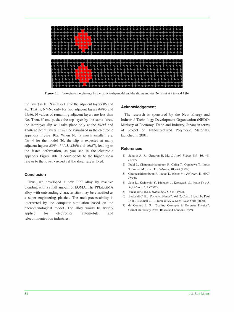
top layer) is 10. N is also 10 for the adjacent layers #5 and#6. That is, N�Nc only for two adjacent layers #4/#5 and#5/#6. N values of remaining adjacent layers are less thanNc. Then, if one pushes the top layer by the same force,the interlayer slip will take place only at the #4/#5 and#5/#6 adjacent layers. It will be visualized in the electronicappendix Figure 10a. When Nc is much smaller, e.g,Nc�4 for the model (b), the slip is expected at manyadjacent layers: #3/#4, #4/#5, #5/#6 and #6/#7), leading tothe faster deformation, as you see in the electronicappendix Figure 10b. It corresponds to the higher shearrate or to the lower viscosity if the shear rate is fixed.
Conclusion
Thus, we developed a new PPE alloy by reactiveblending with a small amount of EGMA. The PPE/EGMAalloy with outstanding characteristics may be classified asa super engineering plastics. The melt-processability isinterpreted by the computer simulation based on thephenomenological model. The alloy would be widelyapplied for electronics, automobile, andtelecommunication industries.
Acknowledgement
The research is sponsored by the New Energy andIndustrial Technology Development Organization (NEDO:Ministry of Economy, Trade and Industry, Japan) in termsof project on Nanostructured Polymeric Materials,launched in 2001.
References
1) Schultz A. R., Gendron B. M.: J. Appl. Polym. Sci., 16, 461
(1972).
2) Ibuki J., Charoensirisomboon P., Chiba T., Ougizawa T., Inoue
T., Weber M., Koch E.: Polymer, 40, 647 (1999).
3) Charoensirisomboon P., Inoue T., Weber M.: Polymer, 41, 6907
(2000).
4) Sato D., Kadowaki Y., Ishibashi J., Kobayashi S., Inoue T.: e-J.
Soft Mater., 3, 1 (2007).
5) Bucknall C. B.: J. Mater. Sci., 8, 514 (1973).
6) Bucknall C. B.: “Polymer Blends”, Vol. 2, Chap. 21, ed. by Paul
D. R., Bucknall C. B., John Wiley & Sons, New York (2000).
7) de Gennes P. G.: “Scaling Concepts in Polymer Physics”,
Cornel University Press, Ithaca and London (1979).
54 e-J. Soft Mater.
Figure 10. Two-phase morphology by the particle-slip model and the sliding movies; Nc is set at 9 (a) and 4 (b).