structure form flying buttresses...
TRANSCRIPT

Revue européenne de génie civil. Volume 9 – n° 9-10/2005, pages 1191 to 1217
Structure and Form of Early Gothic Flying Buttresses M. A. Nikolinakou* — A. J. Tallon** J. A. Ochsendorf*** *Graduate Research Assistant, ***Assistant Professor Massachusetts Institute of Technology 77 Massachusetts Av., 1-343b Cambridge, MA 02139 {mariakat, jao}@mit.edu **Graduate Research Assistant, Columbia University 2960 Broadway New York, NY 10027-6902 [email protected]
ABSTRACT: This paper explores the structural function of early Gothic flying buttresses. Their effectiveness is evaluated under minimum thrust conditions using conventional limit analysis. The significance of various formal characteristics of the flying buttress (length, intrados curvature, thickness, inclination) as well as probable failure modes (sliding and support displacement), are investigated both parametrically and using a series of twenty French early Gothic flyers. The results permit us to address certain long-standing art-historical assumptions and demonstrate that the method of study proposed here holds promise for future exploration for all types of flying buttresses—not just those from the early Gothic period. RÉSUMÉ. Cet article explore la fonction structurelle des arcs-boutants du début gothique. Leur efficacité est évaluée dans des conditions de poussée minimale en utilisant une analyse limite conventionnelle. L’importance des diverses caractéristiques formelles de l’arc-boutant (longueur, courbure de l’intrados, épaisseur, inclinaison) ainsi que ses modes probables d’effondrement (glissement et déplacement des supports), sont analysés paramétriquement et en utilisant une série de vingt arcs-boutants gothiques français. Les résultats nous permettent de remettre en question certaines suppositions d’historiens d’art existantes de longue date et démontrent que la méthode d’étude proposée ici est prometteuse pour une future exploration de tous types d’arcs-boutants, et non pas seulement ceux du début gothique. KEY WORDS: masonry, limit analysis, Gothic architecture, flying buttress MOTS-CLÉS: maçonnerie, analyse limite, architecture gothique, arc-boutant

1192 Revue européenne de génie civil. Volume 9 – n° 9-10/2005
Demander une église gothique sans arcs-boutants, c’est demander une navire sans quille ; c’est pour l’église comme pour le navire une question d’être ou de n’être pas.
Eugène-Emmanuel Viollet-le-Duc (1858)
1. Introduction
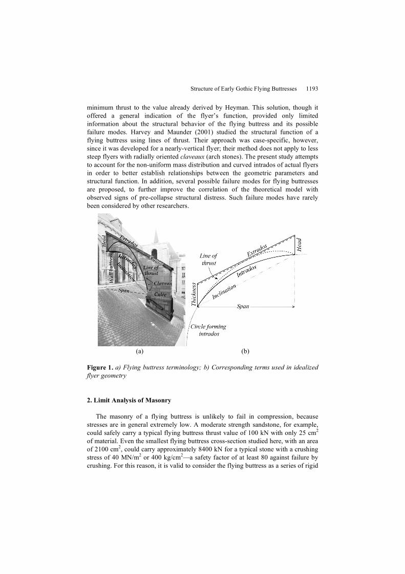
The flying buttress (figure 1a) is often considered the quintessential element of Gothic architecture—the most visible sign of the startling developments in building technology that took place between 1130 and the end of the twelfth century in France. Generations of scholars have puzzled over the invention, deployment, and continuing modification of this remarkable engineering feature, which made possible the quest for extraordinary building height. Yet few historians or engineers have devoted attention to the precise structural function of the flying buttress.
While there is mention of the flying buttress by writers from the late Gothic period onwards, it is not until the mid-nineteenth century that its constructional, historical, and to a certain extent structural functions are addressed at length by French restoration architect and theorist Eugène-Emmanuel Viollet-le-Duc (1858). In the late-nineteenth century in Germany, Georg Ungewitter (1890) applied graphic static analysis techniques, which had been refined over the course of the nineteenth century in France, to the study of Gothic buildings, and devoted considerable attention to the flying buttress. Other important contributions were made by Louis Barbier (1930), who used graphic analysis techniques to demonstrate that flying buttresses were structurally unnecessary in the churches of Saint-Germain-des-Prés in Paris and the Cathedral of Noyon, and by George Rosenberg (1936), who is perhaps the first to insist on the importance of the flying buttress for resisting wind, a point further developed by architect and historian John Fitchen (1955). Jacques Heyman (1995) provided the clearest application of limit analysis to the structure of the flying buttress, and Robert Mark (1982), using photoelastic modeling, made important advances in our understanding of the role of the flying buttress in the context of Gothic building structure as a whole. Yet the great majority of studies has concerned the “mature” flying buttresses of the thirteenth century, while the critical experiments in early Gothic buttressing have been largely neglected. And though the art historical discussion of early flying buttresses1 has improved their classification and chronology, it has contributed little to our precise understanding of their structural role.
Several studies have analyzed the structural behavior of the flying buttress in terms of its geometry by abstracting its form to a simple parallelogram. Heyman (1966) derived and discussed the analytical solution for the passive thrust of such a flyer as a function of its length, thickness and inclination. McDermott (1998) attempted to solve a trapezoidal geometry, but his assumptions of uniform weight distribution and hinge formation at the middle of the span constricted the final
1. See a cursory list of references in the bibliography.
Structure of Early Gothic Flying Buttresses 1193
minimum thrust to the value already derived by Heyman. This solution, though it offered a general indication of the flyer’s function, provided only limited information about the structural behavior of the flying buttress and its possible failure modes. Harvey and Maunder (2001) studied the structural function of a flying buttress using lines of thrust. Their approach was case-specific, however, since it was developed for a nearly-vertical flyer; their method does not apply to less steep flyers with radially oriented claveaux (arch stones). The present study attempts to account for the non-uniform mass distribution and curved intrados of actual flyers in order to better establish relationships between the geometric parameters and structural function. In addition, several possible failure modes for flying buttresses are proposed, to further improve the correlation of the theoretical model with observed signs of pre-collapse structural distress. Such failure modes have rarely been considered by other researchers.
(a) (b)
Figure 1. a) Flying buttress terminology; b) Corresponding terms used in idealized flyer geometry
2. Limit Analysis of Masonry
The masonry of a flying buttress is unlikely to fail in compression, because stresses are in general extremely low. A moderate strength sandstone, for example, could safely carry a typical flying buttress thrust value of 100 kN with only 25 cm2 of material. Even the smallest flying buttress cross-section studied here, with an area of 2100 cm2, could carry approximately 8400 kN for a typical stone with a crushing stress of 40 MN/m2 or 400 kg/cm2—a safety factor of at least 80 against failure by crushing. For this reason, it is valid to consider the flying buttress as a series of rigid
1194 Revue européenne de génie civil. Volume 9 – n° 9-10/2005
blocks, whose equilibrium conditions can be examined without reference to the elasticity of the material. The blocks of the flying buttress are assumed to be made of stone of unit weight 24kN/m3 which have infinite compressive and no tensile strength, as is generally done in the application of limit analysis to unreinforced masonry (Heyman 1995). The standard assumption that the blocks have sufficient friction to prevent sliding, however, is re-examined.
The structural behavior of unreinforced masonry is thus a problem of stability, not strength, and, using the principles of static equilibrium, can be evaluated geometrically. Since forces move longitudinally through the flying buttress, the flyer can be “flattened” into a two-dimensional shape (see figure 2). Because it has more than the number of support constraints required for equilibrium, a flying buttress is statically indeterminate, or hyper-static. Any of its infinite number of possible thrust states can be represented by a line of compressive force within the confines of the flyer shape (Heyman 1966). While the working thrust state, which is in constant flux in response to forces such as wind, ground movement, mortar creep, vibration, and thermal expansion, is generally unknown, the maximum and minimum thrusts, as defined by the flyer shape, are unique.2 A study of these limits makes it possible not only to better understand the present-day safety of the structure but to gain insight into the design principles of the medieval builder.
Like the modern engineer, the medieval builder’s primary concern was to provide support for a range of loads—for which he could only have an intuitive, experiential grasp—while avoiding failure. His research tools were the flying buttresses themselves. If they required only the maintenance due to their constant exposure to the elements, the builder knew that working thrusts were being handled successfully. Cracking, displacement, or collapse, on the other hand, taught him that the limits of design were being attained—and that the design needed to change. Just as modern limit analysis looks to the extremes for answers, then, so also did the medieval builder use signs of structural distress to balance safety against structural and aesthetic daring.
2.1. Minimum thrust
The minimum, or passive thrust state, is the condition in which the flying buttress exerts the smallest possible outward force on neighboring elements, or, stated in another way, the minimum horizontal force required to keep the claveaux of the flying buttress together. The minimum thrust state is described geometrically by a line of thrust which has the steepest possible rise able to fit within the confines of the flyer shape (see figure 2).
2. Open cracks reduce the number of possible equilibrium solutions (thrusts cannot pass through them) and can thus help indicate the regions of the flyer through which force must pass.

Structure of Early Gothic Flying Buttresses 1195
2.2. Maximum thrust
The maximum thrust state is the condition in which the flying buttress transmits the greatest possible force before failure. This failure can be caused by three possible mechanisms: stone crushing, the collapse of the flyer itself, or the failure of supporting elements. Each of these mechanisms must be examined, for the actual maximum thrust will be determined by the mechanism that fails first. As discussed earlier, failure by crushing is unlikely. Mark (1972), for example, calculated a maximum wind force of 1100 kN per bay for Chartres Cathedral, a force that could be accommodated by the smallest flying buttress studied here with a safety factor of 7.5. The maximum thrust state is described geometrically by a line of thrust which has the shallowest possible rise able to fit within the confines of the flyer shape (see figure 2). A flyer will become unstable when this line reaches the bounds of intrados and extrados, and will fail when the hinges required for a collapse mechanism are formed.3 Unlike the flyer form indicated in figure 2, the early Gothic flying buttresses studied here are all able to accommodate a perfectly straight line, the equivalent of an infinite compressive force. The maximum thrust state for this failure mechanism is thus dependent not on the flying buttress form itself but rather on the stability of the supporting elements—the clerestory wall (the upper wall of the central vessel) on one side and the culée and pier buttress (the downward extension of the culée below the roof) on the other. The calculation of the maximum thrust state as determined by specific failure mechanisms—whether due to shear, outward rotation, or other factors—is beyond the scope of this paper.
Minimum thrust
Maximum thrust
Figure 2. Generic flyer with minimum and maximum thrust states (after Heyman 1995)
3. It is assumed here that hinge locations are points at the edge of the masonry. This assumption is slightly unsafe, because as Heyman (1966) demonstrates, the line of thrust must pass through a finite area—thus at a distance from the edge of the masonry of at least five percent of its depth.

1196 Revue européenne de génie civil. Volume 9 – n° 9-10/2005
3. Analyses
Figure 3. Test case flying buttresses, drawn at the same scale

Structure of Early Gothic Flying Buttresses 1197
Table 1. Key to flyer abbreviations
Blois, north B Nouvion-le-Vineux Nv Blois, hemicycle south Ba Pontigny chevet Pc Blois, hemicycle north Bb Pontigny nave Pn Champeaux Cx Reims R Châteaudun Cd Saint-Germain-des-Prés Sg Etampes E Saint-Leu-d'Esserent Sl Laon, Notre-Dame Lc Sens Se Laon, Saint-Martin Lm Soissons Ss Mantes M Vézelay Ve Noirlac Nc Voulton Vo
3.1. Case studies
Twenty French flying buttresses were analyzed to determine the range of their structural behavior. These flyers, whose forms (the actual buttresses are in most cases either heavily restored or rebuilt) are assumed to date from the mid- to late-twelfth century, were chosen both for their importance in the discussion of early Gothic structure and also to represent the range of flyers found in typical twelfth-century churches. Flying buttress geometry was obtained photogrammetrically by the second author from the actual buildings or by tracing drawn sections in the cases where the flying buttress has either disappeared or been replaced. The structural analysis of these flying buttresses makes it possible to better understand their formal differences, and to address longstanding art-historical and structural assumptions.
An automated graphic structural analysis tool, developed with the aid of Cabri Geometry II interactive geometry software,4 was used to determine the line of minimum horizontal thrust for each of the twenty early Gothic flying buttresses considered here.5 This is only one of the many techniques available for the analysis of rigid block structures, the most recent of which have been made possible by advances in computer modeling (for a comprehensive review see Boothby 2001). Among these, discrete element methods (DEM) are particularly promising: by allowing not only the individual modeling of stones but also the incorporation of the properties of their contact surfaces (Bicanic et al. 2002), they enable the simulation of slippage and interpenetration (crushing) between blocks, as well as dynamic loading (Mamaghani et al. 1999, Azevedo et al. 2000). Despite these advantages, discrete element analysis methods, along with other finite element methods, are highly sensitive to the properties of the stone and mortar (friction angle, cohesion,
4. This interactive analysis tool is freely available at http://web.mit.edu/masonry. 5. The many books on graphic statics published between 1850-1950 present these techniques in great detail. For a recent overview, see Zalewski and Allen (1997).
1198 Revue européenne de génie civil. Volume 9 – n° 9-10/2005
tensile strength and fracture energy, for example) used as input for the model; in a medieval masonry building, these properties vary widely and are, as in the case of remotely placed flyers, very difficult to acquire. The present thrust line analysis method, based rather on concepts of geometry and stability, is less sensitive to material parameters. It furthermore presents a more straightforward and visual calculation of the structural behavior. This is well-suited to the two-dimensional character of the flying buttresses, their uncertain material properties, and the high compressive strength of the stone. Three-dimensional problems, however, may require the use of more complex modeling methods.
The method of graphic statics was used to determine the centroid of each flying buttress segment, to construct the funicular polygon, and to determine the support reactions. It was assumed, conservatively, that the coping does not function together with the rest of the flyer, and that the line of thrust was therefore confined within the main flyer body. All reported thrusts are normalized by weight to permit comparison among flyers with different dimensions. When possible, actual joints between claveaux are included in the geometric model and are used in the analyses to check for potential sliding failures. The flying buttresses and their calculated lines of minimum thrust are summarized in figure 3.6 Table 1 provides a key to the abbreviations used in the figures.
3.2. Parametric analyses
A series of parametric analyses was performed in parallel with the case studies to investigate specific geometric characteristics using the idealized flying buttress shown in figure 1b. Flyer length, culée thickness, flyer inclination and intrados curvature, described by circular segments with varying radii, are considered as variables. By limiting the number of parameters studied, it is possible to identify certain trends in structural behavior that might not have been apparent otherwise.
4. Minimum thrust analysis
4.1. Generic flying buttress
As Heyman (1966) showed, a flying buttress of constant thickness has a unique analytical solution for the minimum thrust value. Because of symmetry, the extrados hinge will always occur at the center of a flat arch, even if it is inclined at various angles; the horizontal thrust is thus independent from flyer inclination. The moment equilibrium of one half of a constant-thickness flying buttress gives:
6. Masonry below the level of the flyer springing point is not indicated, since the minimum thrust calculations do not depend on the exact geometry of the culée.

Structure of Early Gothic Flying Buttresses 1199
t
L
W
H
8= [1]
and !"
#$%
&+= 'tan4
12
1
t
L
W
Vc [2]
where θ is the angle and t the thickness of the flyer, H is the minimum horizontal thrust, Vc the vertical reaction at the culée, and W the weight of the flyer. The vertical reaction at the head Vh together with the culée reaction Vc must sum to equal the weight of the flyer W.
Equation [1] illustrates that flying buttresses with the same L/t ratio have the same minimum horizontal thrust, regardless of inclination. Furthermore, for a given span L, the horizontal thrust is inversely proportional to the thickness t (figure 4). Very thin flying buttresses cannot provide sufficient depth for variations in the form of the thrust line and thus require a considerable minimum thrust to prevent the claveaux from separating. On the other hand, increasing the thickness beyond a certain point only marginally decreases the minimum thrust, because the weight also increases substantially.
Length L (m)
Thickness
Flyer geometry
Flyer angle
L (m)Line4 812
0.0
0.2
0.4
0.6
0.8
1.0
1.2
1.4
1.6
0 1 2 3 4 5 6
Flyer thickness (m)
Figure 4. Minimum thrust for flat arches as described by equation [1]
More realistic geometries are described by a variable thickness along the span and by a curved intrados. In such asymmetrical cases, the extrados hinge location moves away from the midpoint and depends on the flyer form and the distribution of

1200 Revue européenne de génie civil. Volume 9 – n° 9-10/2005
its mass. As shown by figure 5, intrados arches described by circle segments with small radii, like those of the case study flying buttresses, exert lower minimum thrusts due to reduced weight; the flat parallelogram arch provides only an upper bound on the possible minimum thrust values for a given flying buttress geometry. In the following five sections, aspects of the structural behavior of the flying buttress are studied in this new context.
0.35
0.40
0.45
0.50
0.55
10 100 1000 10000
Radius of intrados arc (m)
Length Angle (400)
Flyer geometryL/t = 4
Thickness
Varied intrados curvatureFlat arch, eq. [1]
Figure 5. Effect of a curving intrados on the minimum thrust value
4.2. Flying buttress length
The structural function of the flying buttress is to transmit force from the upper walls and vaults of the main vessel of a church over the aisles to the culées and exterior pier buttresses. Some churches, such as Notre-Dame in Paris (nave section shown in figure 6), however, have more than one aisle over which the support must reach. Art historians have in general tacitly assumed that a flying buttress long enough to make this leap—with perhaps a ten- to twelve-meter span—would have been technically impossible in the early- to mid-twelfth century, as noted by Murray (1998). It has been supposed, partly for this reason, that Notre-Dame was originally equipped with two short flying buttresses, each of which spanned a single aisle.7 The
7. The twelfth-century forms of the flying buttresses of Notre-Dame of Paris are not certain enough to have been included in the present study. For a discussion, see Murray (1998).

Structure of Early Gothic Flying Buttresses 1201
results of a parametric analysis in which the flying buttress length-over-thickness ratio is varied against flyer inclination, presented in figure 6a, shed new light on this question.
Stated in the simplest terms, smaller flyers exert smaller forces than larger flyers—independent of flyer angle. This was noted by Heyman (1966), who showed furthermore that the passive thrust of a large flying buttress is much greater than that developed by a structural system composed of a series of two shorter ones linked together to span the same distance. Longer flyers require greater force to keep their stones together; stated in another way, they exert larger horizontal forces on their supporting elements. This might be of concern for long flying buttresses supported by tall culées, which must be sprung from a high enough point to clear the roofs of the aisles. Not only is a tall culée more susceptible to outward rotation, but long flying buttresses are more sensitive to such outward displacements of their supports (discussed in section 4.6 below). A longer flyer is thus more difficult to deploy because it depends to a greater extent on the immobility of its supports.
Parametric analysesEstimation by eq. [3]
0.20
0.30
0.40
0.50
0.60
0.70
0.80
0 10 20 30 40 50 60
Flying buttress angle
6
4
3
LengthThickness
Variable:
Example of shapes:8
LengthAngle
Flyer geometry
Sliding failureFriction coefficient: 0.75
(a)
0 10 20 30 40 50 60
0.20
0.30
0.40
0.50
0.60
0.70
0.80
Flying buttress angle
NvBa
B
Cx
Cd
LcLm
NcPc
M
Se
Sg
Ss
Ve
E
PnSl
Vo
R
(b)
Figure 6. a) Minimum horizontal thrust values for flying buttresses with varying length-over-thickness ratios and different inclinations; b) Corresponding thrust values for case study early Gothic flyers
The results shown in figure 6a also reveal that a good first estimation of the minimum horizontal thrust of a flyer can be obtained by:
!!"
#$$%
&'
ThicknessFlyer
LengthFlyerWH
10min
[3]
Structural analysis of the various scenarios of choir and nave flying buttress support will be undertaken in a subsequent article.
1202 Revue européenne de génie civil. Volume 9 – n° 9-10/2005
This value is lower than that obtained by equation 1, since the intrados curvature is now accounted for, and the extrados hinge is correctly located.
The case study flying buttresses are plotted in figure 6b at the same scale as the parametric results of figure 6a. Despite a fairly wide range in flyer span (from 2.5 to 8 meters), these flyers, and, by extrapolation, most early Gothic flying buttresses, which cluster together in the same region of the graph, exert remarkably similar horizontal forces (roughly 1/3 of the flyer weight). As a result they make less stringent demands on their supports: they more easily tolerate outward displacements, and exert less thrust. It cannot be said for certain whether this seeming avoidance of very long flying buttresses, even in cases where multiple aisles had to be spanned, is evidence of a constructional “technical impossibility,” or rather of a well-placed structural intuition honed by experience of actual building problems.
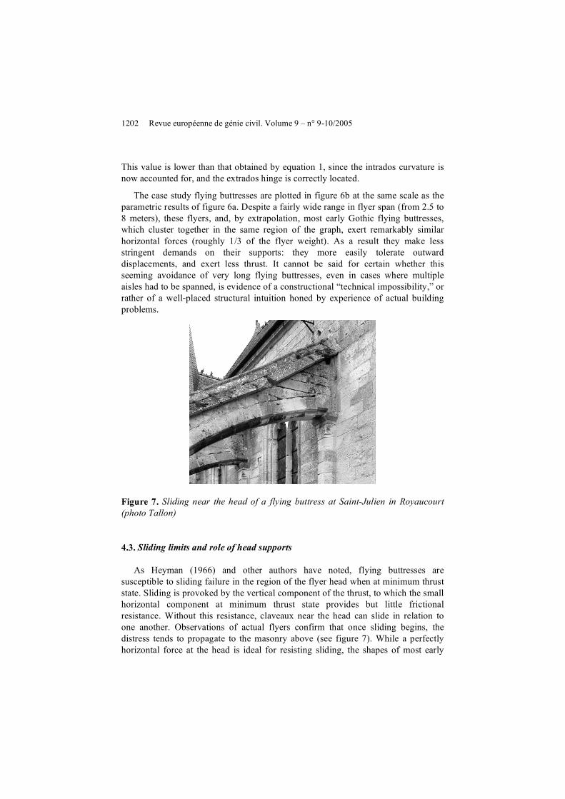
Figure 7. Sliding near the head of a flying buttress at Saint-Julien in Royaucourt (photo Tallon)
4.3. Sliding limits and role of head supports
As Heyman (1966) and other authors have noted, flying buttresses are susceptible to sliding failure in the region of the flyer head when at minimum thrust state. Sliding is provoked by the vertical component of the thrust, to which the small horizontal component at minimum thrust state provides but little frictional resistance. Without this resistance, claveaux near the head can slide in relation to one another. Observations of actual flyers confirm that once sliding begins, the distress tends to propagate to the masonry above (see figure 7). While a perfectly horizontal force at the head is ideal for resisting sliding, the shapes of most early

Structure of Early Gothic Flying Buttresses 1203
Gothic flying buttresses are such that this is rarely the case.8 If the friction coefficient for the masonry were 0.75, then flyers which fall in the shaded area in figures 6a and 9a would collapse due to sliding between the claveaux.9 Figure 6a shows that short flyers are thus more vulnerable to sliding than their longer counterparts, whose higher passive thrust is sufficient to prevent even unbonded stones from failure by sliding. As is made clear in figure 6b, whose axis scale is identical to that of 6a, nearly all case study flyers are susceptible to sliding failure at minimum thrust state.
It seems that early Gothic builders were aware of this problem, for in certain buildings (including nine of those studied) the flyer head is supported on a wall buttress (see figure 1a). For those flying buttresses whose heads rest against the wall without support from below, the vertical reaction at the head is provided solely by frictional resistance, and the interface between the first claveau and the wall is the most susceptible to sliding failure. For flyers with head supports, determination of the critical surface requires close examination of both the configuration of the claveaux relative to the wall buttress and of the general arrangement of stones.
Table 2. Flyers with heads leaning against the clerestory wall
Church Current factor of
safety against sliding (fs=0.75)
Friction coefficient
needed Blois, north 0.90 0.83 Blois, axial south 0.53 1.42 Blois, axial north 0.64 1.17 Etampes 0.43 1.73 Laon, Saint-Martin 0.30 2.49 Noirlac 2.55 0.29 Pontigny, chevet 0.96 0.78 Saint-Germain-des-Prés 0.66 1.14 Saint-Leu-d'Esserent 0.78 0.96 Vézelay 0.99 0.76 Voulton 1.53 0.49
8. Heyman (1966) notes that in the flying buttresses of certain English buildings, such as Lichfield Cathedral, the line of minimum thrust is nearly horizontal at the flyer head. 9. It is assumed for parametric analyses that the flyer claveaux are jointed radially; for both parametric analyses and case studies it is assumed that the sliding condition is governed by a rather conservative estimate of the friction coefficient for mortared stone of 0.75, as suggested by Coulomb (1773). While actual measurements of the friction coefficients of each of the twenty flyers would have been of interest, they were technically beyond the scope of this investigation.
1204 Revue européenne de génie civil. Volume 9 – n° 9-10/2005
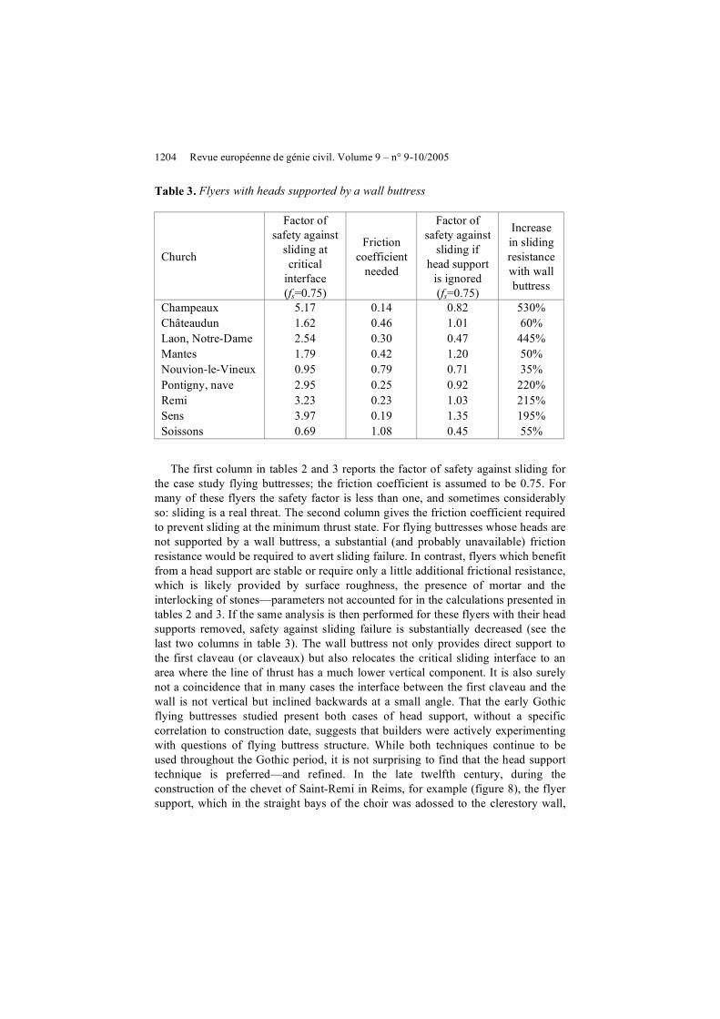
Table 3. Flyers with heads supported by a wall buttress
Church
Factor of safety against
sliding at critical
interface (fs=0.75)
Friction coefficient
needed
Factor of safety against
sliding if head support
is ignored (fs=0.75)
Increase in sliding resistance with wall buttress
Champeaux 5.17 0.14 0.82 530% Châteaudun 1.62 0.46 1.01 60% Laon, Notre-Dame 2.54 0.30 0.47 445% Mantes 1.79 0.42 1.20 50% Nouvion-le-Vineux 0.95 0.79 0.71 35% Pontigny, nave 2.95 0.25 0.92 220% Remi 3.23 0.23 1.03 215% Sens 3.97 0.19 1.35 195% Soissons 0.69 1.08 0.45 55%
The first column in tables 2 and 3 reports the factor of safety against sliding for the case study flying buttresses; the friction coefficient is assumed to be 0.75. For many of these flyers the safety factor is less than one, and sometimes considerably so: sliding is a real threat. The second column gives the friction coefficient required to prevent sliding at the minimum thrust state. For flying buttresses whose heads are not supported by a wall buttress, a substantial (and probably unavailable) friction resistance would be required to avert sliding failure. In contrast, flyers which benefit from a head support are stable or require only a little additional frictional resistance, which is likely provided by surface roughness, the presence of mortar and the interlocking of stones—parameters not accounted for in the calculations presented in tables 2 and 3. If the same analysis is then performed for these flyers with their head supports removed, safety against sliding failure is substantially decreased (see the last two columns in table 3). The wall buttress not only provides direct support to the first claveau (or claveaux) but also relocates the critical sliding interface to an area where the line of thrust has a much lower vertical component. It is also surely not a coincidence that in many cases the interface between the first claveau and the wall is not vertical but inclined backwards at a small angle. That the early Gothic flying buttresses studied present both cases of head support, without a specific correlation to construction date, suggests that builders were actively experimenting with questions of flying buttress structure. While both techniques continue to be used throughout the Gothic period, it is not surprising to find that the head support technique is preferred—and refined. In the late twelfth century, during the construction of the chevet of Saint-Remi in Reims, for example (figure 8), the flyer support, which in the straight bays of the choir was adossed to the clerestory wall,

Structure of Early Gothic Flying Buttresses 1205
was transformed into an independent column in the hemicycle bays. This had the added benefit of allowing unrestricted passage along the upper wall and windows.
Using the stated coefficient of friction of 0.75, eleven of the twenty case studies would experience sliding failure at a state of minimum thrust, as indicated in tables 2 and 3. How, then, are these flying buttresses still standing? There are two possible explanations: first, the specific combination of stone and mortar may provide a greater static coefficient of friction than the value assumed. Second, because of outward pressure from the vaults, the flying buttress may not be in a state of minimum thrust; the required thrust values for the flying buttress thus enter the clerestory wall at an angle closer to the horizontal. It is worth noting that flyers with large frictional resistance “deficits,” such as that at Saint-Martin in Laon, should the thrust descend towards the minimum value, would fail by sliding long before a sufficient number of hinges form to enable the collapse of the structure as a whole.
Figure 8. Reims, Saint-Remi, south choir clerestory (photo Tallon)
1206 Revue européenne de génie civil. Volume 9 – n° 9-10/2005
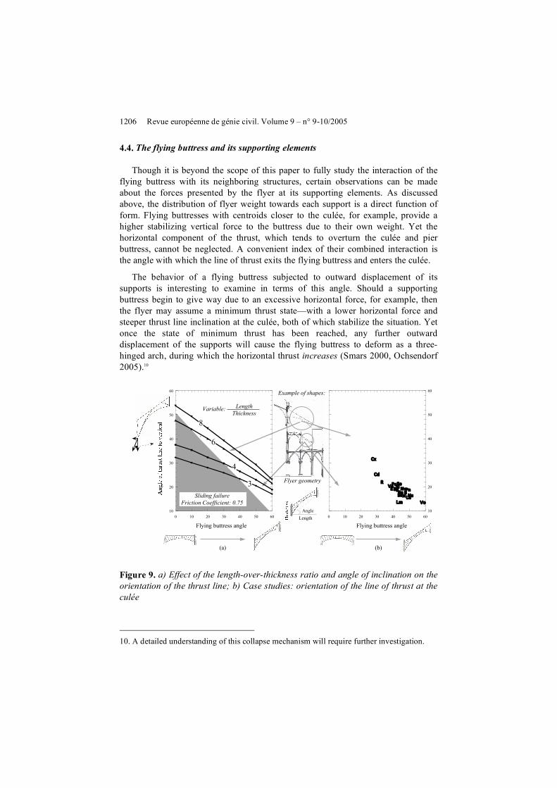
4.4. The flying buttress and its supporting elements
Though it is beyond the scope of this paper to fully study the interaction of the flying buttress with its neighboring structures, certain observations can be made about the forces presented by the flyer at its supporting elements. As discussed above, the distribution of flyer weight towards each support is a direct function of form. Flying buttresses with centroids closer to the culée, for example, provide a higher stabilizing vertical force to the buttress due to their own weight. Yet the horizontal component of the thrust, which tends to overturn the culée and pier buttress, cannot be neglected. A convenient index of their combined interaction is the angle with which the line of thrust exits the flying buttress and enters the culée.
The behavior of a flying buttress subjected to outward displacement of its supports is interesting to examine in terms of this angle. Should a supporting buttress begin to give way due to an excessive horizontal force, for example, then the flyer may assume a minimum thrust state—with a lower horizontal force and steeper thrust line inclination at the culée, both of which stabilize the situation. Yet once the state of minimum thrust has been reached, any further outward displacement of the supports will cause the flying buttress to deform as a three-hinged arch, during which the horizontal thrust increases (Smars 2000, Ochsendorf 2005).10
LengthAngle
Flyer geometry
10
20
30
40
50
60
0 10 20 30 40 50 60
Flying buttress angle
8
6
4
3
LengthThickness
Variable:
Example of shapes:
Sliding failure Friction Coefficient: 0.75
(a)
10
20
30
40
50
60
0 10 20 30 40 50 60
Flying buttress angle
NvBa B
Cx
Cd
LcLm
Nc
Pc
M
SeSg
Ss
VeE PnSl
Vo
R
(b)
Figure 9. a) Effect of the length-over-thickness ratio and angle of inclination on the orientation of the thrust line; b) Case studies: orientation of the line of thrust at the culée
10. A detailed understanding of this collapse mechanism will require further investigation.
Structure of Early Gothic Flying Buttresses 1207
The effects of flyer inclination and length/thickness ratio on thrust angle are shown in figure 9a. The plot confirms the analyses of a number of scholars, such as Wolfe and Mark (1974), who write that “when the angle of the flyer is raised…the top of the pier buttress is also given more stability by the greater vertical component of the thrust it receives.” Figure 9b, at the same scale as figure 9a, shows that for the case study flying buttresses as well, shallower flyers have lines of thrust that enter the culée and pier buttress in a more horizontal fashion. The culée and pier buttress are thus obliged to resist a greater force which tends to induce both outward rotation and shear stresses—without the benefit of a high stabilizing vertical force. It is interesting to note that many early Gothic flyer configurations were later modified through the addition of a stone mass placed directly above the culée, designed to counteract these horizontal forces.
-1.00
-0.50
0.00
0.50
1.00
0 10 20 30 40 50 60
Flying buttress angle
8 6 4 3
Flyer exerts upward vertical force at head
LengthThickness
Variable:
Sliding failure fs = 0.75
Horizontal
thrust only
Example of shapes:
LengthAngle
Flyer geometry
(a)
-1.00
-0.50
0.00
0.50
1.00
0 10 20 30 40 50 60
NvBa
B
CxCd
LcLm
Nc
PcMSe
Sg SsVe
E
PnSl
VoR Bb
Flying buttress angle
(b)
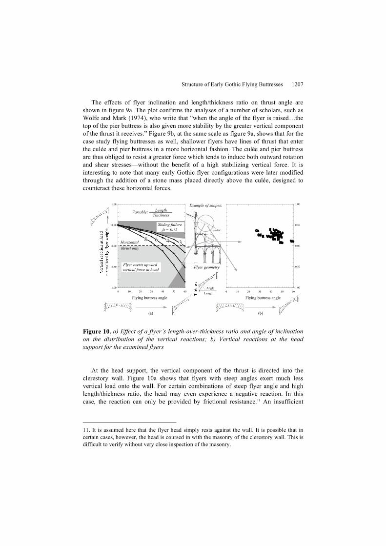
Figure 10. a) Effect of a flyer’s length-over-thickness ratio and angle of inclination on the distribution of the vertical reactions; b) Vertical reactions at the head support for the examined flyers
At the head support, the vertical component of the thrust is directed into the clerestory wall. Figure 10a shows that flyers with steep angles exert much less vertical load onto the wall. For certain combinations of steep flyer angle and high length/thickness ratio, the head may even experience a negative reaction. In this case, the reaction can only be provided by frictional resistance.11 An insufficient
11. It is assumed here that the flyer head simply rests against the wall. It is possible that in certain cases, however, the head is coursed in with the masonry of the clerestory wall. This is difficult to verify without very close inspection of the masonry.

1208 Revue européenne de génie civil. Volume 9 – n° 9-10/2005
coefficient of friction would result in the loss of the vertical kinematic restriction at the head and would thus change the structural configuration of the element.
Figure 10b indicates that all case study flyers transfer part of their weight to the adjacent wall when acting at a state of minimum thrust. Depending on the shape of the flyer, vertical forces imposed at the head vary between 8% and 39% of the flyer weight. A flying buttress such as that at Saint-Martin in Champeaux (Cx in figure 10b) clearly has a greater need for head support—which it receives from a wall buttress. Yet, despite this, there is no discernible correlation between the need for support and the presence of such support. Once again, this could be interpreted as a testament to the climate of experimentation prevalent during the mid- to late- twelfth century in France.
The horizontal thrust of the flyer at the head is met by the upper wall, which is counterbalanced at two levels by the roof truss and by the vaults. It is generally assumed that flying buttresses (or at least their wooden centering arches) were put in place before the vaults, in order to stay the superstructure against wind forces acting on the roof (Fitchen 1961). This may not always have been the case, as demonstrated by Murray (1987): there were deliberations at Troyes Cathedral in the late fifteenth century over whether to construct the nave flying buttresses first or the flyers and vaults at the same time. When flyers were constructed first, the horizontal thrusts generated by their self-weight would have been managed during construction, and would present a problem only in the case of the failure of vaults or roof (or both). The structural behavior of a number of Gothic buildings subjected to bombing during the first World War has shown that the minimum horizontal thrust state which their flyers assumed was not significant enough to upset the equilibrium of the upper clerestory wall, despite the collapse in many cases of both vaults and roof (Fitchen 1961). The resistance of the upper wall to overturning clearly depends on a great many factors: wall thickness, longitudinal bracing, or the type of masonry construction. What can be stated with certainty, however, is that longer flying buttresses, which develop greater horizontal forces, present a greater threat to the stability of the upper wall (see figure 6a). The case study flyers have generally low horizontal thrust values, which vary from 3 kN to 45 kN.
4.5. The intrados of early flying buttresses
Art historians have long used the curvature of the intrados as an index of the construction date of a flying buttress; it is often stated that early flyers have an intrados formed of a “quarter circle.” This assertion will now be examined, and an attempt will be made to connect the shape of the intrados to the structural behavior of the flyer.
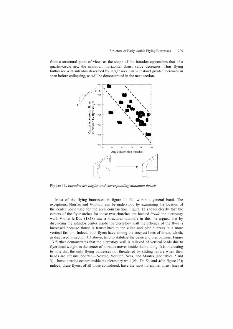
Every case study flying buttress intrados can be described by a single circular arc. They are not all formed of quarter circles, however: the angles which describe the circle segment vary between 55 and 100 degrees. Figure 11 demonstrates that,
Structure of Early Gothic Flying Buttresses 1209
from a structural point of view, as the shape of the intrados approaches that of a quarter-circle arc, the minimum horizontal thrust value decreases. Thus flying buttresses with intrados described by larger arcs can withstand greater increases in span before collapsing, as will be demonstrated in the next section.
0.10
0.15
0.20
0.25
0.30
0.35
0.40
50 60 70 80 90 100
BbBa
B
Cx
Cd
Lc
Lm
NcNv
PcVe
Se
Sg
SsVoE
MPnSl
Angle describing intrados
R
Figure 11. Intrados arc angles and corresponding minimum thrusts
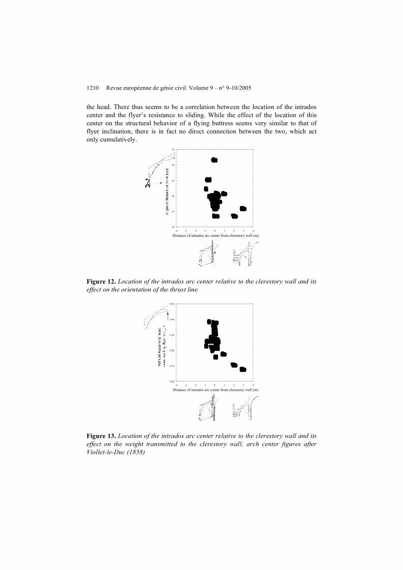
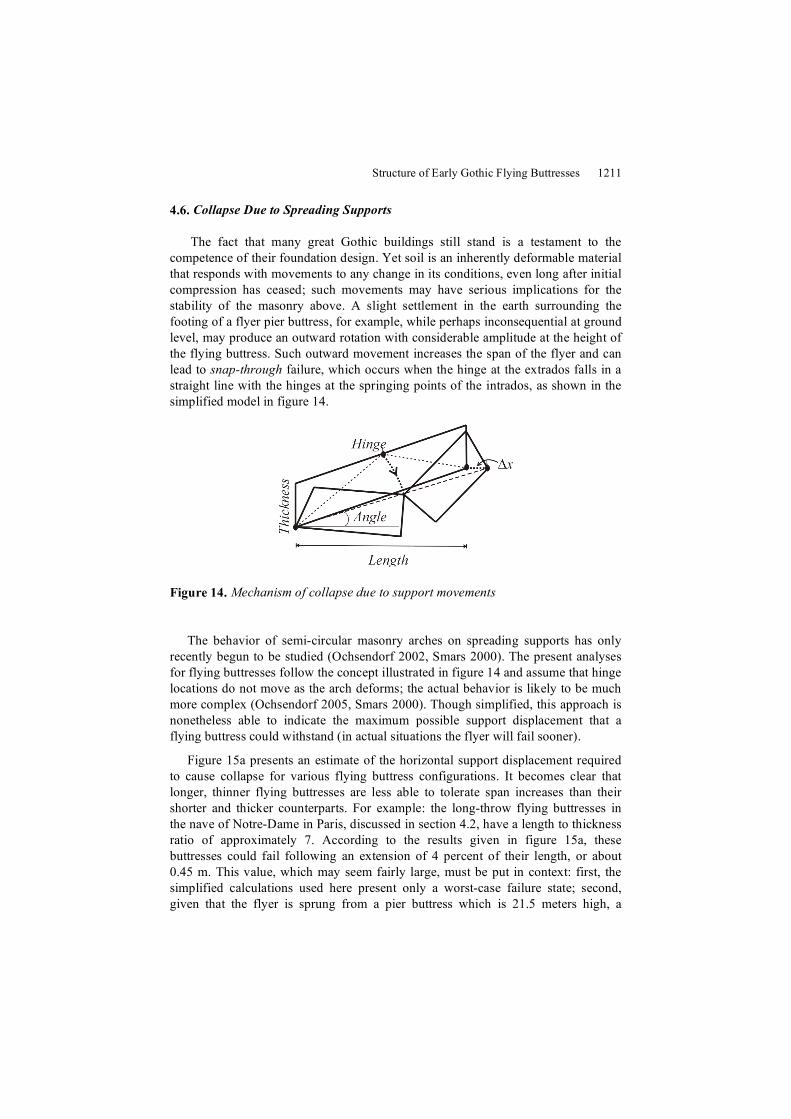
Most of the flying buttresses in figure 11 fall within a general band. The exceptions, Noirlac and Voulton, can be understood by examining the location of the center point used for the arch construction. Figure 12 shows clearly that the centers of the flyer arches for these two churches are located inside the clerestory wall. Viollet-le-Duc (1858) saw a structural rationale in this: he argued that by displacing the intrados center inside the clerestory wall the efficacy of the flyer is increased because thrust is transmitted to the culée and pier buttress in a more vertical fashion. Indeed, both flyers have among the steepest lines of thrust, which, as discussed in section 4.3 above, tend to stabilize the culée and pier buttress. Figure 13 further demonstrates that the clerestory wall is relieved of vertical loads due to flyer dead weight as the center of intrados moves inside the building. It is interesting to note that the only flying buttresses not threatened by sliding failure when their heads are left unsupported—Noirlac, Voulton, Sens, and Mantes (see tables 2 and 3)—have intrados centers inside the clerestory wall (Nc, Vo, Se, and M in figure 13); indeed, these flyers, of all those considered, have the most horizontal thrust lines at
1210 Revue européenne de génie civil. Volume 9 – n° 9-10/2005
the head. There thus seems to be a correlation between the location of the intrados center and the flyer’s resistance to sliding. While the effect of the location of this center on the structural behavior of a flying buttress seems very similar to that of flyer inclination, there is in fact no direct connection between the two, which act only cumulatively.
10
15
20
25
30
35
-4 -3 -2 -1 0 1 2 3 4
BaB
Cx
Cd
Lc
Lm
Nc
NvPcVe Se
Sg
Ss
Vo
E
MPnSl
Distance of intrados arc center from clerestory wall (m)
R
Figure 12. Location of the intrados arc center relative to the clerestory wall and its effect on the orientation of the thrust line
0.00
0.10
0.20
0.30
0.40
0.50
-4 -3 -2 -1 0 1 2 3 4
Ba
B
Cx
Cd
Lc
Lm
Nc
NvPcVe
Se
Sg
Ss
Vo
E
M
PnSlBb
Distance of intrados arc center from clerestory wall (m)
R
Figure 13. Location of the intrados arc center relative to the clerestory wall and its effect on the weight transmitted to the clerestory wall; arch center figures after Viollet-le-Duc (1858)
Structure of Early Gothic Flying Buttresses 1211
4.6. Collapse Due to Spreading Supports
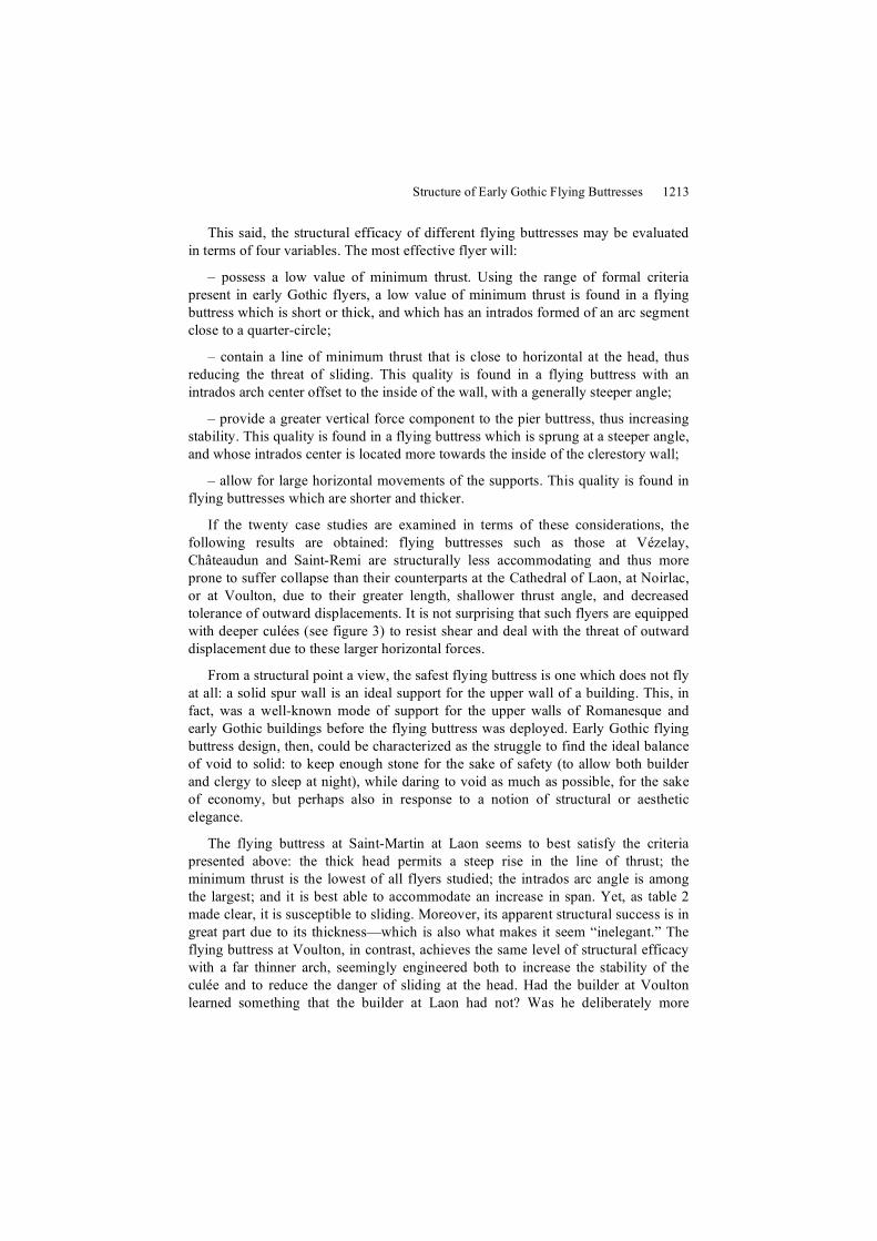
The fact that many great Gothic buildings still stand is a testament to the competence of their foundation design. Yet soil is an inherently deformable material that responds with movements to any change in its conditions, even long after initial compression has ceased; such movements may have serious implications for the stability of the masonry above. A slight settlement in the earth surrounding the footing of a flyer pier buttress, for example, while perhaps inconsequential at ground level, may produce an outward rotation with considerable amplitude at the height of the flying buttress. Such outward movement increases the span of the flyer and can lead to snap-through failure, which occurs when the hinge at the extrados falls in a straight line with the hinges at the springing points of the intrados, as shown in the simplified model in figure 14.
Figure 14. Mechanism of collapse due to support movements
The behavior of semi-circular masonry arches on spreading supports has only recently begun to be studied (Ochsendorf 2002, Smars 2000). The present analyses for flying buttresses follow the concept illustrated in figure 14 and assume that hinge locations do not move as the arch deforms; the actual behavior is likely to be much more complex (Ochsendorf 2005, Smars 2000). Though simplified, this approach is nonetheless able to indicate the maximum possible support displacement that a flying buttress could withstand (in actual situations the flyer will fail sooner).
Figure 15a presents an estimate of the horizontal support displacement required to cause collapse for various flying buttress configurations. It becomes clear that longer, thinner flying buttresses are less able to tolerate span increases than their shorter and thicker counterparts. For example: the long-throw flying buttresses in the nave of Notre-Dame in Paris, discussed in section 4.2, have a length to thickness ratio of approximately 7. According to the results given in figure 15a, these buttresses could fail following an extension of 4 percent of their length, or about 0.45 m. This value, which may seem fairly large, must be put in context: first, the simplified calculations used here present only a worst-case failure state; second, given that the flyer is sprung from a pier buttress which is 21.5 meters high, a

1212 Revue européenne de génie civil. Volume 9 – n° 9-10/2005
displacement of 0.45 m corresponds to a pier buttress rotation of only one degree from the vertical.
0
10
20
30
40
50
60
70
0 20 40 60 80
Flying buttress angle
L/t = 2
468
3
Sliding failure Friction coefficient: 0.75
(a)
0
10
20
30
40
50
60
70
0 20 40 60 80
Flying buttress angle
Nv
Ba
BCxCd
Lc
Lm
NcPc
MSe
Sg
Ss
Ve
E
PnSl
Vo
Bb
R
(b)
Figure 15. a) Plot of required horizontal support movements to cause collapse; b) Maximum tolerable increase in flying buttress span before collapse (actual critical displacement is smaller)
Figure 15b plots results for the case study flying buttresses according to the same criteria. It is clear that most cannot withstand an increase in their span greater than twenty percent. Despite certain anomalous results (Saint-Martin in Laon, Lm in figure 15b), this approach holds promise for a more nuanced understanding of the behavior of masonry structures; further work must now be done to refine the calculations.
4.7. Summary
Each subsection above has presented conclusions based on a limited set of structural parameters. Yet they all function together: the behaviors seen in the parametric analyses must be synthesized in the flying buttress taken as a whole. An even larger context must also be acknowledged: as stated above, the conclusions presented here are made without a full consideration of the interaction of the flying buttress with the entire structural system of the church. While it is useful to consider each flying buttress as a structural element in order to understand the advantages of its particular geometry, the exact placement of the flying buttress in the building and its relationship to neighboring elements will ultimately determine its effectiveness.
Structure of Early Gothic Flying Buttresses 1213
This said, the structural efficacy of different flying buttresses may be evaluated in terms of four variables. The most effective flyer will:
– possess a low value of minimum thrust. Using the range of formal criteria present in early Gothic flyers, a low value of minimum thrust is found in a flying buttress which is short or thick, and which has an intrados formed of an arc segment close to a quarter-circle;
– contain a line of minimum thrust that is close to horizontal at the head, thus reducing the threat of sliding. This quality is found in a flying buttress with an intrados arch center offset to the inside of the wall, with a generally steeper angle;
– provide a greater vertical force component to the pier buttress, thus increasing stability. This quality is found in a flying buttress which is sprung at a steeper angle, and whose intrados center is located more towards the inside of the clerestory wall;
– allow for large horizontal movements of the supports. This quality is found in flying buttresses which are shorter and thicker.
If the twenty case studies are examined in terms of these considerations, the following results are obtained: flying buttresses such as those at Vézelay, Châteaudun and Saint-Remi are structurally less accommodating and thus more prone to suffer collapse than their counterparts at the Cathedral of Laon, at Noirlac, or at Voulton, due to their greater length, shallower thrust angle, and decreased tolerance of outward displacements. It is not surprising that such flyers are equipped with deeper culées (see figure 3) to resist shear and deal with the threat of outward displacement due to these larger horizontal forces.
From a structural point a view, the safest flying buttress is one which does not fly at all: a solid spur wall is an ideal support for the upper wall of a building. This, in fact, was a well-known mode of support for the upper walls of Romanesque and early Gothic buildings before the flying buttress was deployed. Early Gothic flying buttress design, then, could be characterized as the struggle to find the ideal balance of void to solid: to keep enough stone for the sake of safety (to allow both builder and clergy to sleep at night), while daring to void as much as possible, for the sake of economy, but perhaps also in response to a notion of structural or aesthetic elegance.
The flying buttress at Saint-Martin at Laon seems to best satisfy the criteria presented above: the thick head permits a steep rise in the line of thrust; the minimum thrust is the lowest of all flyers studied; the intrados arc angle is among the largest; and it is best able to accommodate an increase in span. Yet, as table 2 made clear, it is susceptible to sliding. Moreover, its apparent structural success is in great part due to its thickness—which is also what makes it seem “inelegant.” The flying buttress at Voulton, in contrast, achieves the same level of structural efficacy with a far thinner arch, seemingly engineered both to increase the stability of the culée and to reduce the danger of sliding at the head. Had the builder at Voulton learned something that the builder at Laon had not? Was he deliberately more

1214 Revue européenne de génie civil. Volume 9 – n° 9-10/2005
daring, or motivated by aesthetic concerns? Could something as delicate as an evolution in flyer design—that would depend on very exact building dates, which in most cases do not exist—be postulated? While these questions are fascinating to pose, they can be answered only with speculations. What is hoped is that the new structural criteria for the evaluation of flying buttress performance will serve to refine and expand the discussion not only of early Gothic flying buttresses but those of later periods as well.
5. Conclusions
1. Thrust line analysis provides a simple but powerful tool for the minimum thrust calculation of any flyer shape and the correct determination of the extrados hinge location.
2. An upper bound for the minimum thrust of a flyer is given by the flat arch analytical solution as Hmin=WL/8t, where W is the weight of the flying buttress. This solution, however, cannot predict the location of the extrados hinge for non-parallelogram shapes.
3. For actual flyers with curved intrados, a good approximation of the minimum thrust is Hmin=WL/10t.
4. Short flyers can accommodate lower forces in minimum thrust conditions, but they are more vulnerable to sliding at the head region.
5. The inclination of a flyer has little effect on the minimum thrust value but affects the direction with which the thrust line enters the pier buttress. Steeper flyers contribute more to the stability of the buttress.
6. As the angle of the flyer increases, most of the vertical load is transferred to the culée support, relieving the clerestory wall. Certain geometries may even result in a negative reaction at the head support.
7. All flyers studied transmit part of their weight to the clerestory wall under the conditions of minimum thrust.
8. Early Gothic flyers are relatively steep and cluster about a small range of low minimum horizontal thrusts.
9. Flyers that lean against the head wall and take no advantage of a wall buttress support are more likely to collapse due to sliding.
10. The structural behavior of the studied flyers agrees very well with the theoretical results of the parametric analyses.
11. The intrados of all cases studied can be described by a single circle, but not all intrados are quarter-circles. An intrados closer to a quarter circle can accommodate lower horizontal force values and therefore can withstand greater displacements.
Structure of Early Gothic Flying Buttresses 1215
12. Most early flyers studied have an intrados defined by a center located in the vicinity of the head wall. Construction considerations may justify this practice, since this places the center on or in front of the head wall, which may have been useful for constructing the timber falsework to support the flying buttress during construction.
13. Offset centers improve the structural efficacy of the flying buttress since they direct the flyer thrust to the pier buttress at a steeper angle, providing a stabilizing action to the supporting buttress. As the center of the intrados moves inside the building, less of the flyer vertical load is transferred to the clerestory wall. Flyers with offset intrados centers also tend to render the thrust more horizontal at the head, which reduces the threat of sliding failure.
14. Offset intrados centers do not necessarily imply steeper flyer angles; both geometrical parameters, however, have similar effects on the interaction of the flyer with its neighboring elements.
Acknowledgements
The authors would like to thank Philippe Block and Thierry Ciblac for their assistance in developing the interactive flying buttress computer models. Jacques Heyman and Stephen Murray read early versions of the paper and offered helpful comments. Financial support for this research was provided by the MIT France program, the Mellon Foundation, and the Georges Lurcy Educational Trust.
6. Bibliography
Azevedo, J., G. Sincraian, and J.V. Lemos, “Seismic behavior of blocky masonry structures”, Earthquake Spectra 16, no. 2, 2000, p. 337-367.
Barbier, L., “Etude sur la stabilité des absides de Noyon et de Saint-Germain-des-Prés”, Bulletin Monumental 89, 1930, p. 515-529.
Bicanic, N., C. Stirling, and C.J. Pearce, “Discontinuous modeling of masonry bridges”, Computational Mechanics 31, 2003, p. 60-68.
Boothby, T.E., “Analysis of masonry arches and vaults”, Progress in structural engineering and materials 3, 2001, p. 246-256.
Bony, J., French Gothic Architecture of the 12th and 13th Centuries, Berkeley, 1983.
Branner, R., “Gothic Architecture 1160-1180 and its Romanesque Sources”, Acts of the 20th International Congress of the History of Art, vol. 1, 1963, p. 92-104.
Coulomb, C., “Essai sur une Application des Règles de Maximi et Minimi à Quelques Problèmes de Statique Relatifs à l'Architecture” (1773), trans. and ed. Jacques Heyman, Coulomb’s memoir on statics: An essay in the history of civil engineering, Cambridge, 1972, reprinted 1997.

1216 Revue européenne de génie civil. Volume 9 – n° 9-10/2005
Fitchen, J., “A comment on the function of the upper flying buttress in French Gothic architecture”, Gazette des Beaux-Arts 45, 1955, p. 69-90.
Fitchen, J., The Construction of Gothic Cathedrals, Oxford, 1961.
Frankl, P., The Gothic: literary sources and interpretations through eight centuries, Princeton, 1960.
Grodecki, L., “Les arcs-boutants de la cathédrale de Strasbourg et leur origine”, Gesta 15, 1976, p. 43-51.
Harvey, B. and E. Maunder, “Thrust line analysis of complex masonry structures using spreadsheets”, Historical Constructions, Guimarães 2001, p. 521-528.
Henriet, J., “La cathédrale Saint-Etienne de Sens: le parti du premier maître et les campagnes du XIIe siècle”, Bulletin Monumental 140, 1982, p. 81-174.
Heyman, J., “The stone skeleton”, International Journal of Solids and Structures, vol. 2, 1966, p. 249-279.
Heyman, J., The stone skeleton: structural engineering of masonry architecture, Cambridge University Press, 1995.
James, J., “Evidence for Flying Buttresses before 1180”, Journal of the Society of Architectural Historians 51, September 1992, p. 261-287.
Lefèvre-Pontalis, E., “L’origine des arcs-boutants”, Congrès archéologique 82, 1919, p. 367-396.
Mamaghani, I.H.P., O. Aydan, and Y. Kajikawa, “Analysis of Masonry Structures under Static and Dynamic Loading by Discrete Finite Element Method”, Structural engineering/earthquake engineering 16, no. 2, 1999, p. 75s-86s.
Mark, R., Experiments in Gothic Structure, Cambridge, MA, 1982.
Mark, R., “The structural analysis of gothic cathedrals,” Scientific American, 1972, p. 90-99.
McDermott, J., “Leaning-Structure Statics – Flying Buttresses and Mayan Vault Ceilings”, Journal of Architectural Engineering, vol. 4 no. 2, June 1998, p. 75-81.
Murray, S., Building Troyes Cathedral: the Late Gothic Campaigns, Bloomington, 1987.
Murray, S., “Notre-Dame of Paris and the Anticipation of Gothic”, Art Bulletin 80, 1998, p. 229-253.
Ochsendorf, J., “Collapse of Masonry Structures”, Ph.D. Dissertation, Department of Engineering, Cambridge University, Cambridge, England, 2002.
Ochsendorf, J., “Masonry Arches on Spreading Supports”, Submitted to The Structural Engineer, London, 2005.
Plagnieux, P., “L’abbatiale de Saint-Germain-des-Prés et les débuts de l’architecture gothique”, Bulletin Monumental 158, 2000, p. 6-87.
Prache, A., “Les arcs-boutants au XII siècle”, Gesta 15, 1976, p. 31-42.
Rosenberg, G., “The Functional Aspects of the Gothic Style”, Journal of the Royal Institute of British Architects 43, 1936, p. 273-290, 364-371.

Structure of Early Gothic Flying Buttresses 1217
Smars, P., Etudes sur la stabilité des arcs et voûtes: confrontation des méthodes de l’analyse limite aux voûtes gothiques en Brabant, Ph.D. Dissertation, Katholieke Universiteit Leuven, 2000.
Ungewitter, G.G., Lehrbuch der gotischen konstruktionen, Leipzig, 1890-1892.
Viollet-le-Duc, E.-E., “Arc-boutant”, Dictionnaire raisonné de l’architecture française du XIe au XVIe siècle, Paris, vol. 1, 1858, p. 60-83.
Wolfe, M. and R. Mark, “Gothic Cathedral Buttressing: The Experiment at Bourges and its Influence”, Journal of the Society of Architectural Historians 33, 1974, p. 17-26.
Zalewski, W. and E. Allen, Shaping Structures: Statics, John Wiley, New York, 1997.