structure design and characteristic … · ross (1987a; 1987 b; ross, 1992) ... problems, and...
TRANSCRIPT

VOL. 12, NO. 3, FEBRUARY 2017 ISSN 1819-6608
ARPN Journal of Engineering and Applied Sciences ©2006-2017 Asian Research Publishing Network (ARPN). All rights reserved.
www.arpnjournals.com
821
STRUCTURE DESIGN AND CHARACTERISTIC ANALYSIS OF
BUCKLING STRENGTH ON SWEDGE FRAME PRESSURE
HULL WITH FINITE ELEMENT ANALYSIS
Ahmad Fauzan Zakki
1, Dong Myung Bae
2, Sulistiyono Susilo
1, Eli Akim Sipayung
1 and Suharto
3
1Department of Naval Architecture, Diponegoro University, Semarang, Central Java, Republic of Indonesia 2Department of Naval Architecture and Marine Systems Engineering, Pukyong National University,
Nam-gu Daeyon Busan, Republic of Korea 3Janata Marina Indah Shipyard and Vocational Program of Naval Architecture, Diponegoro University,
Semarang, Central Java, Republic of Indonesia
E-Mail: [email protected]
ABSTRACT
This study discusses design and analysis of the strength of submarine’s inner hull, which uses swedge frame, in
Pasopati Submarine owned by the Indonesian Ministry of Defence. The study analyzes pressure hull in various depths (100
meters, 300 meters, and 500 meters), with the use of 35 mm plate thickness, and the T profile size. While modeling is done
with the FEM software, buckling analysis will make use of a software. The making of the model design, followed by an
analysis of the model, will generate an output or data, i.e. calculation in the form of model images, analysis finding, and
parameters of the necessary data, such as the rate of stress voltage, location of the critical point due to pressure, and
security level of the construction.
Keywords: buckling strength, swedge frame pressure hull, finite element analysis, structure design, characteristics.
INTRODUCTION
Along with the development of offshore industry,
several types of submarine can be used for the benefit of
supply and maintenance on offshore buildings, in either
fixed or submersible platform. In general, construction of
inner hull in a submarine has two types, namely ring frame
pressure hull and swedge frame pressure hull. Swedge
Frame Pressure Hull is intended to (1) maximize the
existing space on the submarine so that materials and
economic value for the shipbuilding are cheaper, and to
(2) strengthen the submarine itself so that it becomes
better.
The growing trend in submarine design shows the
need for the increase of depth level for both industrial and
military sectors. Moreover, the complexity of modern
submarine and the demand for efficiency, safety, and
greater reliability become a challenge for designers in
making the submarine design, especially in the pressure
hull components. Determination of the design must
consider its specification, which includes type, main size,
speed, and others.
In general, the structure of a submarine consists
of two hulls, namely outer hull and inner hull. The outer
hull serves to control the influence of hydrodynamic loads.
This part is called hydrodynamic hull. In the other hand,
the inner hull serves to withstand hydrostatic pressure
when the submarine is in diving condition. Based on the
functions used to withstand the pressure, this part is
commonly referred to as pressure hull (American Bureau
of Shipping, 1993). The design of pressure hull is a
combination of cylinder, cone, and dome shape built to
withstand the pressure as a result of diving at a high depth
level. The increased pressure for additional depths of 100
feet is followed with the increased hydrostatic pressure of
44.5 psi for the standard sea water and 43.5 psi for the
fresh water (Carlberg, 2011).
The depth level to which the pressure hull
structure has failed is so-called collapse depth. One topic
that attracts a naval architect is the power of the
submarine. Consideration of the submarine’s strength
deals with the fact that a submarine built too strong will be
very heavy, slow, and require a greater cost for it
definitely uses construction with large dimensions and
thickness. Moreover, the burden of heavy construction
would hamper the submarine to reach the top speed during
operation as planned when designed. The submarine will
be slow and take time to operate. Conversely, when the
submarine is too weak, it will be at high risk of structural
failure. This is due to the structure. In this case, the
construction uses lightweight construction and has a thin
dimension. This is done for cost savings in the submarine
construction, so that most likely it will not be able to
withstand the varied loads during operation, from either
inside or outside the submarine.
In this study, the design of pressure hull in a
submarine with missile launchers will be developed.
Based on the numerical results of non-linear static analysis
on the hydrostatic pressure with operational depth
condition, this study seeks to provide maximum
operational depth level taken from elastic to plactic
behavior variations. Calculation of the swedge frame
strength will be done in this study. This research is
expected to give significant contribution to the
development of submarine technology.
This study aims to formulate the manufacture of
structural design of swedge frame pressure hull of a
submarine, and to know the strength value in it at a depth
of 100, 300, and 500 meters. This study is restricted with a
linear static analysis calculation. The plates used in the

VOL. 12, NO. 3, FEBRUARY 2017 ISSN 1819-6608
ARPN Journal of Engineering and Applied Sciences ©2006-2017 Asian Research Publishing Network (ARPN). All rights reserved.
www.arpnjournals.com
822
design is an Alloy Steel HY 80 type, σ minimum yield strength of 80 ksi (552 MPa), thickness of 35 mm, and
loading conditions in maximum stress and maximum
displacement. Furthermore, the entire test conducted refers
to ABS Rules for Buildind and Classing Underwater
Vehicles, Systems, Hiperbaric Facilities 2002 Concept
Design of a Commercial Submarine.
LITERATURE REVIEW
Pressure hull
Weight of a submarine depends on the maximum
depth. Greater diving depth level requires a larger pressure
hull. The depth level used as a design consideration
includes operational or normal depth level; maximum
permitted depth level, and collapse depth level.
The maximum permitted depth level is the
maximum depth level where a submarine is still safe to
operate. This depth is achieved only on certain conditions.
Collapse depth is the depth where the pressure hull
structure has failed.
Figure-1. Submarine’s Pressure Hull.
Figure-2. Submarine’s pressure hull structure using
swedge frame.
The submarine’s pressure hull is built not only to
withstand hydrostatic pressure but also to withstand a
strong blast shock. In general, collapse depth is a
multiplier between the safety factor and the operating
depth. Carlberg (2011) showed that the value of safety
factor for a submarine ranged between 1.5-2.0. This figure
may be acceptable in engineering. In a military submarine
design, consideration of hydrostatic load at the operating
depth level and the load caused by a blast shock should be
given. In condition of war, the effects of the blast shock
can cause the structure to undergo large deformations,
which can lead to material failure. The large size and the
distance of the explosion provide shock effect of the
underwater explosion. High intensity of waves can also
cause damage to the submarine’s pressure hull, and
gradually some of its equipments does not function
properly (Friedman, 1984).
Figure-3. Front side of the submarine’s pressure hull.
Studies on pressure hull were conducted by
several researchers, particularly in regard to the analysis
and design of submarine’s pressure hull. Gorman and
Louie (1991) developed an optimization method to
examine the material, form, and architecture of the
pressure hull by considering the hull yielding, buckling,
general instability, and instability of failure mode. Jackson
(1992) presented a concept design of submarine, which
later becomes a basis for submarine planning process. By
using Finite Element, Sibarani (2013) analised the
structural design and buckling strength characteristics on
ring frame submarine pressure hull.
Ross (1987a; 1987 b; Ross, 1992) and Ross and
Palmer (1993) reviewed the conventional pressure hull and
novel design. Based on the finite element method and
experiment, Ross (1987a), Ross and Palmer (1993)
proposed an efficiency improvement of dome structure by
changing the dome of a submarine’s pressure hull. Ross
introduced a pressure hull axisymmetric design with
swedge frame to withstand hydrostatic pressure.
Comparison between swedge frame with ring frame has
also been carried out, where, in term of structure, swedge
frame is considered more efficient than conventional ring
frame (Ross, 1987a; Ross, 1992). Ross (1987b) presented
his experiment result showing a plastic failure of the thin
walled ring frame on the conical shell, with pressure load
of external uniform. Yuan, Liang and Ma (1991) presented

VOL. 12, NO. 3, FEBRUARY 2017 ISSN 1819-6608
ARPN Journal of Engineering and Applied Sciences ©2006-2017 Asian Research Publishing Network (ARPN). All rights reserved.
www.arpnjournals.com
823
a theoretical analysis of elastic instability of the cylinder
swedge frame against hydrostatic pressure load by
considering the influence of various angles of conical
section. Yuan et al. (1991) also did an elastoplastic
analysis and non-linear response of Ross’ swedge model
(Ross and Palmer, 1993).
Buckling analysis
Buckling is an instability that leads to the failure
mode (Assakkaf, 2003). Buckling stress may refer to a
process in which a structure is not able to maintain its
original form. This happens because the structure receives
a stress excess resulting on deflection that reshapes the
structure. In a stable structure, buckling can return its
original shape. Meanwhile, if the structure is not able to
return to its original shape, the structure is said to be
failing. Factors influencing on the buckling are elasticity
of materials, size dimensions, loading, and measurement
factor.
Practical aspects of finite element simulation
Manual calculation of buckling occurring in the
pressure hull structure of a submarine will be discussed
using the rule of Hyper Works (2012) about the practical
aspects of finite element simulation. There are several
theories and formulas used to calculate the amount of
pressure boundary in accordance with the components of
swedge frame pressure hull used in the design of the
submarine's pressure hull. Some of them are:
The overall buckling strength is formulated with:
�� = (��� ) � + �����
Where,
Pn = overall pressure of cylinder
Et = modulus elasticity
R = mean of radius
I = moment of inertia of the section composite
consisting of a stiffener
L = distance between stiffeners
The result of pressure with cylindrical stiffener
(swedge frame), including a circular pressure and bending
stress arising from outside the circle, is calculated in
compliance with the following equation:
σy = ������� + �������−�� �
Where, σy = yield point minimum
Pt = cylinder stiffner longitudinal yield
stress pressure
Pyf = pressure in the middle of cylinder
E = modulus elasticity
R = mean of radius
Finite Element Method
The method used in the final work to be made is a
modeling method and finite element analysis. Finite
element method having recently developed has
convincingly become a powerful device for analysis of
various types of plate’s problems and construction structure, because the result is more favorable than
theoretical settlement. The element method will eventually
replace the experimental stress analysis techniques in
determining the strength of the element. The coefficient of
element stiffness that can be used directly has been
generally available and provided precise result. Once the
coefficient is determined, structural system analysis will
show the same result as the matrix methods used in
engineering mechanics of which the computer program
has been available (Prabowo et al, 2016; Zakki et al,
2016).
The accuracy of finite element method is
influenced by the following parameters (arranged in
accordance with its virtues), i.e. movement patterns
defined for the element, the number of elements, loads
presentation techniques, edge conditions of specific
problems, and computer programs. Although the finite
element method is still in the developmental phase, this
method will be widely used later on in many areas of
structural and continuum mechanics. By assuming the real
cases.Bae et al. (2016) stated that finite element method
can produce virtual experimental data. Because the
method is developed by the engineers based on
engineering logic of physics, its development in the future
will be driven by a more exact assessment by the
mathematicians.
Nowadays, most of assessments of the finite
element method is aimed at developing the shape function
or enhanced elements, which can provide a rapid
convergence and better accuracy. In addition, the size and
speed of next-generation computers will require a new
computer program. Application of the basic concepts of
the finite element method today has been expanded to the
problem, such as plate thickness and membrane structure
(shell), non-linear problem (including plasticity), stress
due to temperature, analysis of aeroalastis and hidroelastis
system structure, flow of liquid, post buckling behavior of
the plate, membrane structure (shell), and others.
Finite element method can be viewed as an
extension of the displacement method (for the frame
structure) to continuous problem with two or three
dimensions, such as plates, membrane structure (shell),
and rigid bodies. In this method, the continuum is actually
replaced by an equivalent ideal structure consisting of
unique elements (discrete element). This element is called
finite elements and linked together in a number of nodes.
With regard to the form of displacement or stress
patterns in the element and to the use of energy theories,
we can reduce the matrix of stiffness that connects nodal
forces with nodal displacement on the element. Stiffness
matrix of the elements is then formed in the same way as
in the portal case. If balance requirement is applied at
every node on the ideal structure, a set of simultaneous
algebraic equations can be formed. The solution produces

VOL. 12, NO. 3, FEBRUARY 2017 ISSN 1819-6608
ARPN Journal of Engineering and Applied Sciences ©2006-2017 Asian Research Publishing Network (ARPN). All rights reserved.
www.arpnjournals.com
824
the whole displacement of the nodes, which will be used to
determine all inner stresses. The finite element method is
first applied by R.H Clough (1960) to the problem of
stress by using triangle and rectangle elements (see.
Clough, 1960). This method is later expanded, and now
we can use the elements of a triangle and a rectangle on a
particular plate, elements of four and six areas in three-
dimensional stress analysis, and curved elements on the
problem of membrane structure with single or double
curves. The scope of its application has also been extended
to the issue of stability and vibration. By applying
incremental approach that treats each additional burden in
linear elastic, the problems of material or geometric
nonlinearity have been solved well with this method.
One development of the finite element method is
the finite strip method. In this method, the actual structure
is idealized into lanes which are connected in nodal lines,
while both ends of all lanes are interconnected to form two
opposite edges domain. Displacement and force along the
nodal lines are considered to vary in accordance with the
basic functions specified. Later, the rate of the
displacement and force at a point is obtained by
multiplying the parameters of nodes and the value of basic
functions at that point. Thus, the problem of two-
dimensional plate is reduced to one-dimensional problem,
so that we get quite a lot of savings in the calculation
when compared with finite element approach. Finite nodal
method is particularly useful for the analysis of the bridge
plate that is straight or circular, the bridge with box girder,
and the folding plate (Ghali and Neville, 1978).
Dealing with submarine type, each submarine
contains different objects. The sample of loading system
can be seen when the submarine is in condition of full of
fuels and foods and is combined with various conditions of
the surrounding environment or the waves causing the
submarine in sagging and hogging conditions.
Finite element application in submarine
Finite Element Method (FEM) is a method used
to analyze a construction. This method is now widely used
in the construction of submarine, coastal structures, and
offshore. Basically, the coverage of this method is very
wide, not limited to steel construction but also to the fluid.
Structural analysis using finite element method makes it
possible to obtain stress deployment on the construction
being analyzed. Failure of a construction can be known by
using this analysis and at the point in which the failure is
indicated.
Therefore, it will be easier for designers to make
modification of the construction and to strengthen the
construction that is identified to damage or fail. To analyse
using the finite element method, there are many softwares
created to facilitate the analysis, some of which are MSC
Nastran, Ansys, Algor, Solidwork, etc. Broadly speaking,
these softwares have a working system and same steps in
conducting the analysis, i.e. beginning with the modeling
and followed by meshing, determination of the boundary
conditions, loading, and analysis.
Program of MSC patran
MSC Patran is a helping program for pre- and
post- processing in the finite element method analysis, in
which one software analysis process used is Msc Nastran
as described in the next section. Analysis process of the
finite element method or analysis begins (pre-processing)
from this helping program, i.e. Msc Patran. In general, the
steps employed in using the software of Msc Patran are
described as follows: creating a database and unit, creating
a geometry model, checking and correcting the geometry
errors, determining the loads and boundary condition,
`determining the material and element properties, meshing
process, optimization process and equivalence, and
analysis process.
MSC Nastran (MacNeal Schewendler
Corporation NASA Structural Analysis) is a finite element
program created and developed by NASA (National
Aeronautics and Space Administration) for solving the
structure and component analysis. The first is static
analysis which consists of static analysis with changes in
surface and stiffness, and buckling analysis. The second is
dynamic analysis which consists of normal model
analysis, response analysis of frequency (harmonics
analysis), transient response analysis, and linear and non-
linear transient response analysis. The third is transient or
steady state heat transfer analysis. In MSC Nastran, the
manufacture of object geometry can be made directly in
the program. Besides, we can also do translating or
geometry importing of objects from CAD (Computer
Aided Design) program in DXF and IGES format, or from
any othe finite element analysis programs, such as
ALGOR, ANSYS, COSMOS, I-DEAS, Mtab*STRESS,
MSCpal and CDA/ Sprint, NASTRAN, PATRAN,
STAAD ISDS, and STARDINE.
METHODOLOGY
Determination of the main size of submarine
In general, there are several requirements in
planning a submarine, namely radius and cruise route,
official speed (Vs), deadweight of submarine (DWT), type
of goods, quantity of goods, and passenger capacity, in
addition to other requirements relating to safety, comfort,
and beauty. These mission requirements become critical
information that will be relied upon by planners of the
vessel to determine its main dimensions that are
compatible in technical and economical aspect.
Submarine design in this study uses a comparison
method. The difference between the comparison
submarine and the proposed submarine is located in height
(h) only, while other measures in both of them are the
same. Here are some methods included in the comparison
method, such as linear regression method, cube root
format, and the geosim procedure.
According to the above explanation, the
comparison method has its advantages, that is, the
arrangement of primary measure calculation is relatively
short. This is due to the submarine’s main dimensions
generated by multiplying the main dimensions of
comparison submarine with the scale factor. However, in

VOL. 12, NO. 3, FEBRUARY 2017 ISSN 1819-6608
ARPN Journal of Engineering and Applied Sciences ©2006-2017 Asian Research Publishing Network (ARPN). All rights reserved.
www.arpnjournals.com
825
the process of determining the submarine’s main
dimensions, we must consider several things, including:
a) Length of submarine (L)
The length of the submarine has an influence on
the speed and strength of elongated submarine. Extra
length of the submarine on displacement condition and
same volume will reduce the resistance of the submarine.
However, it can also lead to an increase in longitudinal
bending stress and a decrease in stability and
maneuverability of the submarine. Addition of the
submarine’s length will reduce engine power at constant
speed, reduce weight of the main engines, reduce fuel
consumption, and enable more stable route of the
submarine.
b) Breadth of submarine (B)
Addition and subtraction on the breadth of the
submarine have an influence on the height metacentra.
Extra breadth of the submarine on displacement condition
and same speed will lead to a high increase in metacentra
(MG), so that the stability of the submarine becomes good.
Extra breadth of the submarine is also used to increase the
breadth the submarine’s rooms.
Data of the submarine’s pressure hull to be
designed in this study is the Pasopati Submarine with 76.6
meters in length, plate type of Alloy Steel HY 80, 6.3
meters in breadth, and 30 mm of plate thickness.
Figure-4. Pressure hull construction of pasopati
submarines.
Assessment of structure strength
In CSR standards, an assessment of the strength
of a structure using Finite Element Analysis is an
obligation. Therefore, the proposed design of a submarine
pressure hull is further analyzed in its structure strength
using MSC Patran and MSC Nastran program. This
analysis will be performed on the hull inner area to find
out how much the Yield Strength happened.
The making of the FE model from the proposed design
The design of geometry and meshing operation is
done using MSC Patran. This program provides a general
need for modeling of geometric elements and FE models.
FE modeling from system design of a submarine’s inner hull construction is illustrated in accordance with the
actual dimensions and includes all existing elements.
Likewise, the material and the properties of the 1D and 2D
elements can be defined and visualized by FEM Software
program to be an 1D element in the form of beam and 2D
element for a hull type of the same size with many
previous studies.
The main structure of submarine construction
consists of inner hull structure and beam. The modeling
process begins by defining the geometry for each element
to be created. The system or coordinate axes of X, Y, Z
(co-ordinate system) in this modeling are:
X-axis: Longitudinal, positive direction points to FWD
Y-axis: Vertical, positive direction points Upwards
Z-axis: Transverse, positive direction points to Port
The submarine modelling is made according to
the length and breadth of its diameter to analyze the
strength of its structure based on the image that is
designed and later imported into the MSC Patran.
Figure-5. FE model of submarine using the
swedge construction.
All major structural components either
longitudinal or transverse must be modeled. Some other
structures in this modeling include:
A dome shape located in the bow and stern of the
submarine
A cylindrical shape located in both the rising and
falling room in the submarine
cylindrical
Conical shape located in a room whose height is at par
with the submarine
The profile used is modeled in the form of beam
Plates modeled in the form of shell
Consisting of four transverse bulkheads

VOL. 12, NO. 3, FEBRUARY 2017 ISSN 1819-6608
ARPN Journal of Engineering and Applied Sciences ©2006-2017 Asian Research Publishing Network (ARPN). All rights reserved.
www.arpnjournals.com
826
Geometry model is created into an interconnected
system, so that it becomes a unity in which each geometry
is defined in accordance with shape, size, and type of
property in each geometry element, such as shell elements
for plate shell geometry, ID beam element for frame
geometry, and so on for all components of the model.
The type of elements used for the finite element
model of the primary structure of submarine includes:
Elements of breadth (shell) to model the hull,
structure, and wrang
Elements of the line (beam) to model the beam
In defining the material, steel with a maximum
stress of 235 GPa = 2.35 x 10¹¹N/ m2 is considered to
have normal strength. The steel’s grade that has normal
strength includes grade A, B, D, and E steel. In the finite
element modeling of submarine construction, material and
Steel A 36 are used with the following properties:
Name of the material: Alloy Steel HY 80 Ksi (552 Mpa)
Modulus Young: 207 Gpa = 2.07 x 10¹¹ N/m2
Density: 7.85 Mg/m³ = 7850 kg/m³
Poisson Ratio: 0.3
The steel used in this structure design is Alloy
Steel HY 80. Steel from this type is commonly used for
military fleets, such as tanks, warships, and submarines.
Determination of the boundary condition
One of the most serious tasks related to the
proper modeling of submarine’s structure with finite
element is the definition of boundary conditions.
Boundary Conditions as called in the finite element
method is the final stage of a finite element modeling, i.e.
the determination of the foundation before the model is
analyzed. Therefore, it can be interpreted also as a
clamping condition that functions to maintain the objects,
so it does not move when analyzed. The move could be in
the form of slide (translation) and rotation. While the
boundary condition is applied to the fore end and the aft
end on the finite element model as a fulcrum of the
analysis, the nodal dots on the fore end and the aft end of
each are connected rigidly against the independent point,
which is also defined as center of gravity of the submarine.
This is done, so that the combination of the loads and the
results of the stress response that occurs can be carried out
maximally for giving the boundary condition on this
submarine model.
Rigid Link is made on the X axis translation and
Y, Z axis rotation, both on aft end (all longitudinal
element) and fore end (longitudinal element) location.
Figure-6. MPC FE model of submarine using
swedge construction.
Figure-6 shows an MPC model where the
Independent Point at the fore end and the aft end has been
determined, i.e. for H 2.125 m, the fore end is at the node
171, and the aft end is at the node 31 072. In boundary
condition of those nodes, the submarine will undergo a
clamping treatment to avoid a shifting and rotation
movement during the analysis. The code in the software is
as follows:
Translational (x, y, z) = <0, 0, 0>
Rotational (x, y, z) = <0, 0, 0>
Rotational (x, y, z) = <0, 0, 0>
Spring elements are divided into Vertical Springs,
i.e. Side, Inner hull, Longitudinal Bulkhead, and
Horizontal Springs including Deck, Inner Bottom, and
Bottom Shell. Calculation of the stiffness of the spring
element uses the following formula (case III-13):
c = ( �+ �) AS –net5��� � = ,77 AS –net5��� �
From calculation the above formula, the stiffness
of the spring element on the model is obtained, i.e. c =
82634144 N/m.
Figure-7. Spring element of the model.
Verification of the model
Verification is carried out after the modeling is
complete. The purpose of this validation is to check the
elements of the model that are made, such as:
Connectivity element is a checking of elements
relationship or connectivity. All elements must connect
each other. If they are not connected, the model cannot be
analyzed.
Duplicate node is a measure that aims to
determine the absence of nodes that are duplicated or
VOL. 12, NO. 3, FEBRUARY 2017 ISSN 1819-6608
ARPN Journal of Engineering and Applied Sciences ©2006-2017 Asian Research Publishing Network (ARPN). All rights reserved.
www.arpnjournals.com
827
doubled. If the nodes are duplicated, the model cannot be
analyzed.
Duplicate element is a checking intended to
eliminate one element that overlaps and is not required. If
some elements overlap, the model cannot be analyzed.
Consistent plate normal is a checking aimed at
restoring the normal vector that is in wrong direction. The
area must have a uniform direction, so that the direction of
the applied load will not uniform. This condition will
cause an error in analyzing the voltage structure.
Guilding element is an element whose normal
vector is used as a reference to alter the normal vector that
is wrong. Error in the normal vector is crucial to be
corrected, especially when the load is in the form of
pressure.
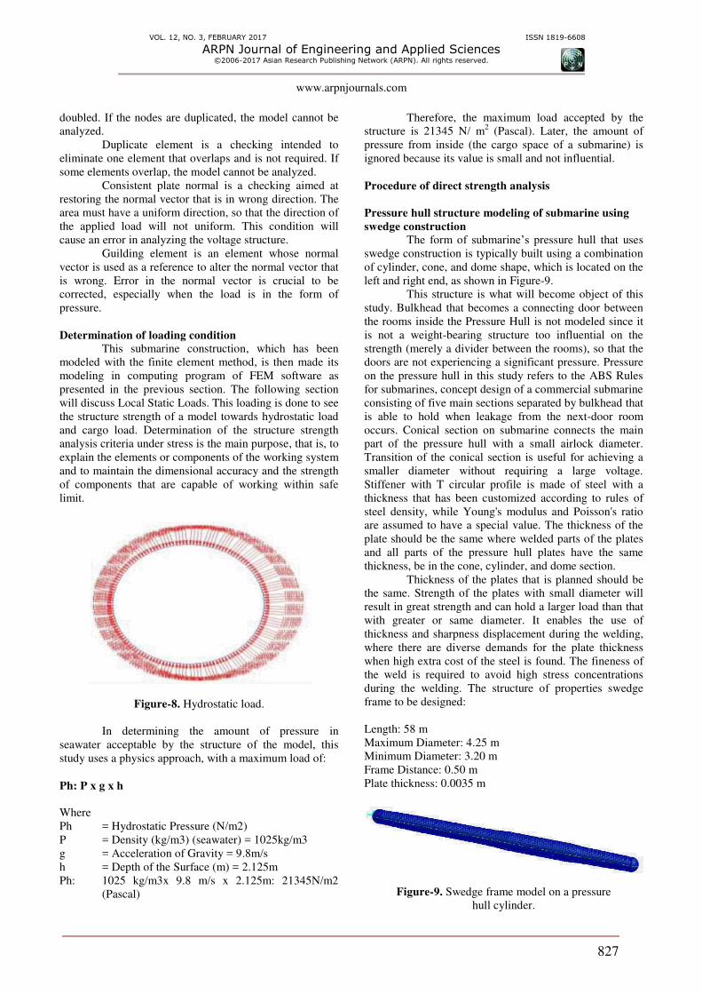
Determination of loading condition
This submarine construction, which has been
modeled with the finite element method, is then made its
modeling in computing program of FEM software as
presented in the previous section. The following section
will discuss Local Static Loads. This loading is done to see
the structure strength of a model towards hydrostatic load
and cargo load. Determination of the structure strength
analysis criteria under stress is the main purpose, that is, to
explain the elements or components of the working system
and to maintain the dimensional accuracy and the strength
of components that are capable of working within safe
limit.
Figure-8. Hydrostatic load.
In determining the amount of pressure in
seawater acceptable by the structure of the model, this
study uses a physics approach, with a maximum load of:
Ph: P x g x h
Where
Ph = Hydrostatic Pressure (N/m2)
P = Density (kg/m3) (seawater) = 1025kg/m3
g = Acceleration of Gravity = 9.8m/s
h = Depth of the Surface (m) = 2.125m
Ph: 1025 kg/m3x 9.8 m/s x 2.125m: 21345N/m2
(Pascal)
Therefore, the maximum load accepted by the
structure is 21345 N/ m2 (Pascal). Later, the amount of
pressure from inside (the cargo space of a submarine) is
ignored because its value is small and not influential.
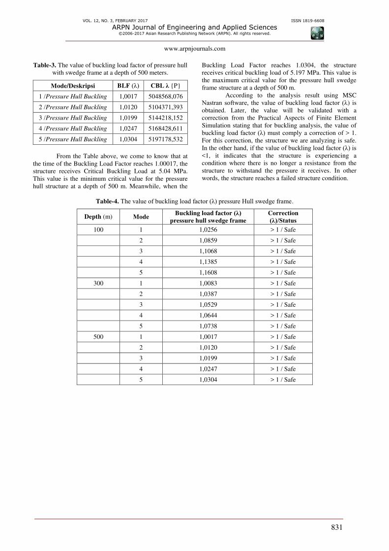
Procedure of direct strength analysis
Pressure hull structure modeling of submarine using
swedge construction
The form of submarine’s pressure hull that uses
swedge construction is typically built using a combination
of cylinder, cone, and dome shape, which is located on the
left and right end, as shown in Figure-9.
This structure is what will become object of this
study. Bulkhead that becomes a connecting door between
the rooms inside the Pressure Hull is not modeled since it
is not a weight-bearing structure too influential on the
strength (merely a divider between the rooms), so that the
doors are not experiencing a significant pressure. Pressure
on the pressure hull in this study refers to the ABS Rules
for submarines, concept design of a commercial submarine
consisting of five main sections separated by bulkhead that
is able to hold when leakage from the next-door room
occurs. Conical section on submarine connects the main
part of the pressure hull with a small airlock diameter.
Transition of the conical section is useful for achieving a
smaller diameter without requiring a large voltage.
Stiffener with T circular profile is made of steel with a
thickness that has been customized according to rules of
steel density, while Young's modulus and Poisson's ratio
are assumed to have a special value. The thickness of the
plate should be the same where welded parts of the plates
and all parts of the pressure hull plates have the same
thickness, be in the cone, cylinder, and dome section.
Thickness of the plates that is planned should be
the same. Strength of the plates with small diameter will
result in great strength and can hold a larger load than that
with greater or same diameter. It enables the use of
thickness and sharpness displacement during the welding,
where there are diverse demands for the plate thickness
when high extra cost of the steel is found. The fineness of
the weld is required to avoid high stress concentrations
during the welding. The structure of properties swedge
frame to be designed:
Length: 58 m
Maximum Diameter: 4.25 m
Minimum Diameter: 3.20 m
Frame Distance: 0.50 m
Plate thickness: 0.0035 m
Figure-9. Swedge frame model on a pressure
hull cylinder.

VOL. 12, NO. 3, FEBRUARY 2017 ISSN 1819-6608
ARPN Journal of Engineering and Applied Sciences ©2006-2017 Asian Research Publishing Network (ARPN). All rights reserved.
www.arpnjournals.com
828
Boundary conditions
Boundary Condition in the analysis process of
finite element method-based software is a phase to
maintain the boundaries (parts to be clamped) of the model
prior to loading and analysis. The clamped parts become
the foundation and unable to move, shift, or rotate. In
pressure hull modeling of a submarine, there are two types
of boundary condition. The first condition is the pressure
hull structure with only one clamping point, which is at
one end of the model. The second condition is by
clamping both ends of the pressure hull.
In this study, the author tends to use the second
condition, because the first condition does not satisfy the
expectation during analysis. This is because there is the
end point that is left free to move, shift, or rotate, so the
fixed end part moves to the pressure exerted.
Figure-10. Boundary condition on the submarine’s
pressure hull using swedge frame.
For the case of boundary condition modeling on
the submarine’s pressure hull, MPC Method is not used to
clamp the pedestal.
Loading conditions
The condition or depth desired by the researcher
in this study in analyzing the characteristics of buckling in
the pressure hull is based on depth variations (100 m, 300
m and 500 m), profile size, and plates used.
Verification of analysis result
The last stage of the analyzing process is
verification of the data, that is, by considering the forms of
buckling characteristics with variations of loading that has
been given. The deflection result of the pressure that has
been given does not become a reference to the writer,
because there is no standardization of the rules applied to
submarines (submarine is a type of special or military
ships).
Variation of loadings
Loading at Depth of 100 m
The load placed on the structure of the
submarine’s pressure hull is the pressure of seawater in
accordance with the conditions of its depth. The pressure
given will suppress the plate element and beam element.
The use of beam dimension on both the pressure hull’s
structures in this study is different.
Figure-11. Beam dimension of pressure hull’s
frames swedge.
By using hydrostatic pressure calculation (h:
depth surface = 102.125 m), the hydrostatic pressure on
the structure of the submarine’s pressure hull using
swedge frame is:
Ph = 1025 kg/m3 x 9.8m/s
2 x 102.125 m
= 1025845.62 N/m2 (Pascal)
= 1.025 MPa
So, the load received by the structure of the
submarine’s pressure hull using swedge frame is 1.025
MPa.
Figure-12. Seawater loading and amount of pressure
for a submarine with swedge frame (100 m).
Loading at Depth of 300 m
By using hydrostatic pressure calculation (h:
depth surface = 302.125 m), the hydrostatic pressure on
the structure of the submarine’s pressure hull using
swedge frame is:
Ph = 1025 kg/m3 x 9.8m/s2 x 302.125 m
= 3034845.62 N/m2 (Pascal)
= 3.034MPa
So, the load received by the structure of the
submarine’s pressure hull using swedge frame is 3.034
MPa.

VOL. 12, NO. 3, FEBRUARY 2017 ISSN 1819-6608
ARPN Journal of Engineering and Applied Sciences ©2006-2017 Asian Research Publishing Network (ARPN). All rights reserved.
www.arpnjournals.com
829
Figure-13. Sea water loading and the amount of pressure
for a submarine with swedge frame (300 m).
Loading at depth of 500 m
By using hydrostatic pressure calculation (h:
depth surface = 502.125 m), the hydrostatic pressure on
the structure of the submarine’s pressure hull using
swedge frame is:
Ph = 1025 kg/m3 x 9.8m/s2 x 502.125 m
= 5043845.62 N/m2 (Pascal)
= 5.043 Mpa
So, the load received by the structure of the
submarine’s pressure hull using swedge frame is 5.043
MPa.
Figure-14. Sea water loading and the amount of pressure
for a submarine with swedge frame (500 m).
Body force
Body force in the process of analysis is defined as
the gravitational force. Therefore, in this sense, the value
of the body force is equal to the force of gravity, i.e. 9.8m/
s2. In the finite element method, it is also known as
Inertial Load.
Figure-15. Body force on the swedge frame model.
RESULT
The amount of the maximum voltage accepted by
the structure, both the plate and beam (swedge frame), in
many variations is as follows:
Plate stress
A depth of 100 m with swedge frame
Figure-16. Buckling condition at depth of 100 m.
Figure-17. Buckling of the pressure hull structure.
In the case of analysis on the submarine’s
buckling pressure hull using swedge frame at a depth of
100 m, 5 cases showing each of their eigenvalues are
produced.

VOL. 12, NO. 3, FEBRUARY 2017 ISSN 1819-6608
ARPN Journal of Engineering and Applied Sciences ©2006-2017 Asian Research Publishing Network (ARPN). All rights reserved.
www.arpnjournals.com
830
Table-1. The value of Buckling Load Factor of pressure
hull with swedge frame at a depth of 100 meters.
Mode/Description BLF (λ) CBL λ {P}
1 /Pressure Hull Buckling 1,0256 1052107,26
2 /Pressure Hull Buckling 1,0859 1113965,75
3 /Pressure Hull Buckling 1,1068 1135405,93
4 /Pressure Hull Buckling 1,1385 1167925,23
5 /Pressure Hull Buckling 1,1608 1190801,59
From the table above, we come to know that at
the time of the Buckling Load Factor reaches 1.0256, the
structure receives Critical Buckling Load at 1.05 MPa.
This value is the minimum critical value for the pressure
hull structure at a depth of 100 m. Meanwhile, when the
Buckling Load Factor reaches 1.1608, the structure
receives critical buckling load of 1.19 MPa. This value is
the maximum critical value for the pressure hull swedge
frame structure at a depth of 100 m.
A depth of 300 m with swedge frame
Figure-18. Buckling condition at a depth of 300 m.
Figure-19. Buckling of the pressure hull structure.
In the case of analysis on the submarine’s
buckling pressure hull using swedge frame at a depth of
300 m, 5 cases showing each of their eigenvalues are
produced.
Table-2. The value of buckling load factor of pressure hull
with swedge frame at a depth
of 300 meters.
Mode/Deskripsi BLF (λ) CBL λ {P}
1 /Pressure Hull Buckling 1,0083 3059731,359
2 /Pressure Hull Buckling 1,0387 3150776,727
3 /Pressure Hull Buckling 1,0529 3195388,958
4 /Pressure Hull Buckling 1,0644 3230289,683
5 /Pressure Hull Buckling 1,0738 3258817,232
From the table above, we come to know that at
the time of the Buckling Load Factor reaches 1.0083, the
structure receives Critical Buckling Load at 3.05 MPa.
This value is the minimum critical value for the pressure
hull structure at a depth of 300 m. Meanwhile, when the
Buckling Load Factor reaches 1.0738, the structure
receives critical buckling load of 3.25 MPa. This value is
the maximum critical value for the pressure hull swedge
frame structure at a depth of 300 m.
A depth of 500 m with swedge frame
In the case of analysis on the submarine’s
buckling pressure hull using swedge frame at a depth of
500 m, 5 cases showing each of their eigenvalues are
produced.
VOL. 12, NO. 3, FEBRUARY 2017 ISSN 1819-6608
ARPN Journal of Engineering and Applied Sciences ©2006-2017 Asian Research Publishing Network (ARPN). All rights reserved.
www.arpnjournals.com
831
Table-3. The value of buckling load factor of pressure hull
with swedge frame at a depth of 500 meters.
Mode/Deskripsi BLF (λ) CBL λ {P}
1 /Pressure Hull Buckling 1,0017 5048568,076
2 /Pressure Hull Buckling 1,0120 5104371,393
3 /Pressure Hull Buckling 1,0199 5144218,152
4 /Pressure Hull Buckling 1,0247 5168428,611
5 /Pressure Hull Buckling 1,0304 5197178,532
From the Table above, we come to know that at
the time of the Buckling Load Factor reaches 1.00017, the
structure receives Critical Buckling Load at 5.04 MPa.
This value is the minimum critical value for the pressure
hull structure at a depth of 500 m. Meanwhile, when the
Buckling Load Factor reaches 1.0304, the structure
receives critical buckling load of 5.197 MPa. This value is
the maximum critical value for the pressure hull swedge
frame structure at a depth of 500 m.
According to the analysis result using MSC
Nastran software, the value of buckling load factor (λ) is
obtained. Later, the value will be validated with a
correction from the Practical Aspects of Finite Element
Simulation stating that for buckling analysis, the value of
buckling load factor (λ) must comply a correction of > 1.
For this correction, the structure we are analyzing is safe.
In the other hand, if the value of buckling load factor (λ) is <1, it indicates that the structure is experiencing a
condition where there is no longer a resistance from the
structure to withstand the pressure it receives. In other
words, the structure reaches a failed structure condition.
Table-4. The value of buckling load factor (λ) pressure Hull swedge frame.
Depth (m) Mode Buckling load factor (λ)
pressure hull swedge frame
Correction
(λ)/Status
100 1 1,0256 > 1 / Safe
2 1,0859 > 1 / Safe
3 1,1068 > 1 / Safe
4 1,1385 > 1 / Safe
5 1,1608 > 1 / Safe
300 1 1,0083 > 1 / Safe
2 1,0387 > 1 / Safe
3 1,0529 > 1 / Safe
4 1,0644 > 1 / Safe
5 1,0738 > 1 / Safe
500 1 1,0017 > 1 / Safe
2 1,0120 > 1 / Safe
3 1,0199 > 1 / Safe
4 1,0247 > 1 / Safe
5 1,0304 > 1 / Safe

VOL. 12, NO. 3, FEBRUARY 2017 ISSN 1819-6608
ARPN Journal of Engineering and Applied Sciences ©2006-2017 Asian Research Publishing Network (ARPN). All rights reserved.
www.arpnjournals.com
832
Table-5. The value of critical buckling load (λ) swedge framepressure hull.
Depth (m) Mode Critical buckling load pressure hull
swedge frame (Mpa)
100 1 1,05
2 1,11
3 1,13
4 1,16
5 1,19
300 1 3,05
2 3,15
3 3,19
4 3,23
5 3,25
300 1 5,04
2 5,10
500 3 5,14
4 5,16
5 5,19
REFERENCES
American Bureau of Shipping. Rules for Building and
Classing Underwater Vehicles, Systems and Hyperbaric
Facilities. Second Printing October 1993. American
Bureau of Shipping: New York, USA.
Assakkaf I. A. 2003. Columns: Buckling (Pinned
Ends) (Doctoral dissertation, University of Maryland,
College Park).
Bae D. M., Prabowo A. R., Cao B., Zakki A. F. and
Haryadi G. D. 2016. Study on collision between two ships
using selected parameters in collision simulation. Journal
of Marine Science and Application. 15(1): 63-72.
Carlberg H. 2011. Concept Design of a Commercial
Submarine. Trondheim: NTNU.
Clough R. W. 1960. The Finite Element Method in Plane
Stress Analysis. Proceedings of 2nd
ASCE Conference on
Electronic Computation, Pittsburgh, PA, September 8-9.
Friedman N. 1984. Submarine design and development.
London: Conway Maritime.
Ghali A. and Neville A. M. 1978. Structural Analysis,
2. Aufiage Chapman and Hall, London.
Gorman J. J. and Louie L. L. 1991. Submersible pressure
hull design parametrics. SNAME Trans. 99: 119-146.
Hyper Works. 2012. Practical Aspects of Finite Element
Simulation, Altair.
Jackson H. A., Fast C., Abels F., Burcher R., Couch R.,
Wood F. and Allmendinger E. 1992. Fundamentals of
submarine concept design. Discussion. Transactions-
Society of Naval Architects and Marine Engineers. 100,
419-448.
Prabowo A. R., Bae D. M., Sohn J. M. and Zakki A. F.
2016. Evaluating the parameter influence in the event of a
ship collision based on the finite element method
approach. International Journal of Technology. 7(4): 592-
602.
Ross C. T. 1987a. A novel submarine pressure hull
design. Journal of Ship Research. 31(3): 186-188.
Ross C. T. 1987b. Design of dome ends to withstand
uniform external pressure. Journal of Ship Research. 31,
139-143.
Ross C. T. 1992. Collapse of inverted hemi-ellipsoidal
shell domes underuniform pressure. Journal of Ship
Research. 36: 378-386.
Ross C. T. and Palmer A. 1993. General instability of
swedge-stiffened circular cylinders under uniform external
pressure. Journal of Ship Research. p. 37.
Sibarani Hendry Maringan. 2013. Desain Struktur dan
Analisa Karakteristik Kekuatan Buckling pada Ring
Frame Pressure Hull Kapal Selam dengan menggunakan
Finite Element Analysis. Semarang: Universitas
Diponegoro.

VOL. 12, NO. 3, FEBRUARY 2017 ISSN 1819-6608
ARPN Journal of Engineering and Applied Sciences ©2006-2017 Asian Research Publishing Network (ARPN). All rights reserved.
www.arpnjournals.com
833
Yuan K. Y., Liang C. C. and Ma Y. C. 1991.
Investigations of the cone angle of a novel swedge-
stiffened pressure hull. Journal of ship research. 35(1): 83-
86.
Zakki A. F., Windyandari A. and Bae. 2016. The
development of new type free-fall lifeboat using fluid
structure interaction analysis. Journal of Marine Science
and Technology. 24(3): 575-580.