structural report proposed basement design carmela & vito
TRANSCRIPT
SY200476-SR02: Carmela & Vito Apartments Structural Report | Rev 4| 24.11.2020 Page 1 of 24
Structural Report – Proposed Basement Design
for
Carmela & Vito Apartments
SY200476-SR02: Carmela & Vito Apartments Structural Report | Rev 4| 24.11.2020 Page 1 of 24
Executive Summary
The following report provides further detailed structural advice regarding the proposed basement
structure design and construction for the proposed apartment development at 23-25 Church Avenue
and 16-18 John Street, Mascot. This report summarises the proposed basement wall design and
addresses the relevant structural engineering queries raised in Bayside Council correspondence DA-
2019/359 dated 1st October 2020.
The development is proposed to be constructed with a reinforced concrete frame. The basement is
proposed to be constructed with Cutter Soil Mix (CSM) basement walls, built via a top-down
construction process with reinforced concrete bored pile foundations, structural steel plunge columns
and reinforced concrete slabs.
In response to the specific queries raised (Geotechnical Requirements (b), (c), (d), (g) & (h) DA-
2019/359 dated 1st October 2020), we make the following comments:
(b) Determine the appropriate means of excavation/shoring in light of point (a) and proximity to
adjacent property and structures. Potential vibration caused by the method of excavation and
potential settlements affecting nearby footings/foundations/buildings shall be discussed and
ameliorated.
A cutter soil mix (CSM) wall is proposed to be constructed to form the basement shoring wall.
A CSM wall is a retention wall constructed by mixing self-hardening slurries with the native
excavated soil. A trench cutting rig with mixing tool excavates vertical panels of soil and
mixes the soil with the binders as the cutting heads extend down. Once the design depth has
been reached, (in this case into the bedrock), the cutting head is extracted and continuously
mixes cement into the wall mix. Prior to hardening, structural steel soldiers are embedded in
the wall matrix to provide the structural frame.
The primary advantages of this method are
• Low vibrations induced in construction of the wall;
• Highly accurate;
• Generally watertight (extremely low permeability); and
• Very little generation of spoil
The body of this report details the structural analysis and design results for the shoring wall.
The predicted horizontal settlements of the shoring walls from our analysis have been
provided in the report and are shown to generally be within tolerable limits.
(c) Determine the required method to temporarily and permanently support the excavation for the
basement adjacent to adjoining property, structures and road reserve
The basement is proposed to be constructed via a top-down construction process. Through
top-down construction, the temporary and permanent support for the basement walls are both
provided by the basement slabs.
All basement walls and foundation piles are constructed from existing ground level and the
supporting slabs are constructed prior to the next stage of excavation below the slab. By
constructing the internal supports (the permanent slabs) prior to the next stage of excavating,
the horizontal settlements of the basement walls are minimised.
(d) Determine the existing groundwater levels in relation to basement structure, tanking and
waterproofing requirement.
Based on results from geotechnical investigation, the ground water level is expected to be at
approximately RL 5.0m (2.0m to 6.0m below existing ground level). The basement excavation
level is proposed to be at approximately RL-3.0m which is below the ground water level.

SY200476-SR02: Carmela & Vito Apartments Structural Report | Rev 4| 24.11.2020 Page 2 of 24
The basement walls are proposed to be socketed into the bedrock strata to create a cut-off
wall and during construction, it is proposed to locally dewater within the site. Use of the cut-off
wall socketed into the low permeability bedrock will greatly assist in controlling the volume of
ground water removed, which results in a minimal effect to the ground water level at adjacent
properties. This is discussed further in the Hydrogeological assessment prepared by CMW
Geosciences.
It is expected that long term seepage through the bedrock will result in hydrostatic pressures
being imposed on the structure. The basement is proposed to be tanked and the base slabs
are designed to withstand the hydrostatic uplift pressures associated with a groundwater level
of RL5.0m
(g) Prepare a construction methodology report demonstrating that the proposed construction
methods (including any excavation, and the configuration of the built structures) will have no
adverse impact on any surrounding property and infrastructure
A detailed construction methodology is outlined in the body of this report. Via the top-down
construction approach, settlements are minimised and there is no drawdown of the adjacent
ground water levels.
(h) Certify that the plans, documentation and construction methodology are satisfactory from a
geotechnical perspective
Further to the information and certification statement in the body of this report, subject to the
approval of a professional geotechnical engineer and hydrogeological consultants, we,
Northrop engineers, being professional structural engineers, see no reason why the proposed
basement design and construction methodology outlined in this report should impact the
stability of the adjacent buildings. The recommended mitigation measures must be
incorporated into the basement design and form part of the proposed peer review.

SY200476-SR02: Carmela & Vito Apartments Structural Report | Rev 4| 24.11.2020 Page 3 of 24
Table of Contents
1. Introduction ...................................................................................................................................... 4
1.1 Project Description .................................................................................................................. 4
1.2 Reference Documentation ...................................................................................................... 4
2. Structural and Geotechnical Summary ............................................................................................ 5
2.1 Structural Summary ................................................................................................................ 5
2.2 Geotechnical Summary ........................................................................................................... 5
3. Proposed Basement Design ............................................................................................................ 7
3.1 Design Loads .......................................................................................................................... 7
3.2 Basement Wall Design Methodology ...................................................................................... 7
3.3 Basement Wall Design Analysis ............................................................................................. 7
3.4 Estimated deflection and deflection monitoring ...................................................................... 8
4. Construction Sequence.................................................................................................................... 9
5. Certification Statement................................................................................................................... 23
Conclusion......................................................................................................................................... 23
References ........................................................................................................................................ 23

SY200476-SR02: Carmela & Vito Apartments Structural Report | Rev 4| 24.11.2020 Page 4 of 24
1. Introduction
Northrop Engineers have been engaged by Da Vito Ferro Apartments to provide further structural
advice regarding the basement design and construction for the subject development. This letter aims
to summarise the proposed basement wall design, and address the relevant structural engineering
queries raised in Bayside Council correspondence DA-2019/359 dated 1st October 2020.
1.1 Project Description
The proposed project encompasses 23-25 Church Avenue and 16-18 John Street, creating a through-
block with a public pedestrian accessway at ground level. The development consists of a three-to-four
storey basement car park, a two-storey mixed-use podium and two 13-storey residential towers. An
existing industrial warehouse will also be incorporated into the podium level.
The site is bounded by John Street to the south, Church Avenue to the north and residential
developments to the east and west. Both developments have basements of differing depths that are
directly adjacent to the proposed basement at 23-25 Church Avenue.
The development at 27 Church Street is currently the subject of legal action from residents of Mascot
Towers, its western neighbour. It is alleged that the excavation and related dewatering of the
basement at 27 Church Street has caused cracking in the basement of Mascot Towers. We
acknowledge that this recent issue has caused concern in the community regarding excavation and
water management for future construction projects in the local area and the design and construction
of basements need to appropriately consider the effects to neighboring properties and infrastructure.
1.2 Reference Documentation
The proposed design of the basement, including shoring wall and foundations has been based on the
following documentation provided to Northrop; as summarised below in Table 1
Item By No. & Revision
Geotechnical Report Aargus Australia GS8023-3A (dated 17/11/2020)
Hydrogeological
Assessment CMW Geosciences SYD2020-0153AB Rev0 (dated 23/11/2020)
Implementation Plan CMW Geosciences SYD2020-0153AC Rev0 (dated 23/11/2020)
Geotechnical Report eiaustralia E24340.G01_Rev1
Geotechnical Report JK Geotechnics 22451SBrpt (dated 29/10/2008)
Architectural Drawings Squillace DA-001 to DA-302 (dated 04/10/2019)
27 Church Street –
Basement Shoring
Drawings
Australian Consulting
Engineers 171233 (October 2017)
21 Church Street –
Structural Drawings
Australian Consulting
Engineers 07AH172 (September 2007)
Council Request for
More Information Bayside Council
DA-2019/359 Letter
1 October 2020

SY200476-SR02: Carmela & Vito Apartments Structural Report | Rev 4| 24.11.2020 Page 5 of 24
2. Structural and Geotechnical Summary
2.1 Structural Summary
The proposed development above ground will consist of post-tensioned concrete floor plates with
reinforced concrete columns and core walls. Precast concrete walls will be used adjacent to the
northern boundary. The main building transfer will occur on level 2 and will be approximately 600-
800mm thick. The structure is proposed to be founded on bedrock, using deep foundation piles.
The proposed shoring wall system is a Cutter Soil Mix (CSM) wall, which is a 750mm wide soil-
cementitious binder mix wall constructed in panels and reinforced with structural steel posts. It uses
the existing soil combined with cement to produce a watertight wall. Compared to more traditional
piled wall systems, its key advantage is that it can build walls to a high degree of accuracy and
therefore low likelihood of any voids between panels. The basement will be socketed into the bedrock
to provide a permanent cut-off for water ingress. Refer to Appendix A for the structural drawings.
Following the installation of the CSM wall, it is proposed to construct the basement using a ‘top down’
approach, where ground floor is constructed prior to excavation, with voids left out for removal of
excavated material. This provides a restraint to the top of the wall, limiting movement of the wall, while
the first basement level is excavated. B1 slab is subsequently installed before excavating to B2. This
staged approach provides regular support to the shoring wall as well as removing the need for
anchors through the walls.
2.2 Geotechnical Summary
The site is underlain by the following subsurface layers:
Material Depth from surface to top of layer (m)
Fill 0
Sand 0.9-1.4
Interbedded sand and clay 9.5-11.3
Residual clay 14.6-15.3
Shale (Class V) 17-20
Shale (Class IV – III) 27
Table 1: Site Substrata
Groundwater is expected to be encountered at depths between 2.0m-6.0m below existing ground
level.
The geotechnical design parameters have been interpreted from the information provided in the
geotechnical reports prepared for this site and referenced above. The geotechnical design
parameters for the foundation piles and the shoring walls are summarised in tables below.
Soil Unit Ultimate End Bearing Pressure
(MPa)
Ultimate Shaft Adhesion in
Compression (KPa)
Residual Clay N/A N/A
Class V Shale 2 100
Class IV Shale 5 150
Class III Shale 20 450

SY200476-SR02: Carmela & Vito Apartments Structural Report | Rev 4| 24.11.2020 Page 6 of 24
Class II Shale 50 700
Table 2: Substrata Capacities
Soil Unit
Unit
Weight
(kN/m3)
Effective
Cohesion
c’ (kPa)
Angle
of
Friction
ϕ’ (⁰)
Elastic
Modulus
(MPa)
Active
Earth
Pressure
Coefficient
At-rest
Earth
Pressure
Coefficient
Passive
Earth
Pressure
Coefficient
Fill and
loose
sand
17 0 28 20 0.36 0.53 2.78
Medium
dense
sand
18 0 35 40 0.27 0.43 3.70
Dense to
very
dense
sand
20 0 38 65 0.24 0.38 4.17
Class V
Shale 22 10 26 50 0.3 0.5 3.0
Class IV
Shale 22 50 28 200 0.3 0.5 3.0
Class III
Shale 24 100 30 350 0.25 0.4 5.0
Table 3: Substrata Parameters

SY200476-SR02: Carmela & Vito Apartments Structural Report | Rev 4| 24.11.2020 Page 7 of 24
3. Proposed Basement Design
3.1 Design Loads
The design loads for the building have been adopted using the provisions of AS1170.0, AS1170.1,
AS1170.2 and AS1170.4.
The design of the basement shoring wall has been carried out to resist the lateral soil pressures and
hydrostatic pressures from the ground water level, together with the following surcharges:
Church Avenue and John Street elevations
• A general surcharge of 15kPa has been applied at ground level
27 Church Street elevation
• The 16 storey concrete framed building is founded on a raft slab at RL -1.50m
• We have calculated a building surcharge load of 160kPa, applied at RL -1.50m
21 Church Street elevation
• The 9 storey concrete framed building is founded on piles.
• A building surcharge load of 10kPa has been applied at RL 7.15m representing the basement
slab
• We have calculated a building surcharge load of 80kPa has been applied at RL0.0m
representing the assumed pile founding depth
3.2 Basement Wall Design Methodology
The CSM shoring wall has been designed and analysed using ‘WALLAP’ retaining wall analysis
software. This is an industry standard tool, considered suitable for this application. The WALLAP
analysis considers one elevation at a time, where wall deflections are considered to interact with the
opposing side, the results are superimposed. The WALLAP analysis has been staged to incorporate
the top-down construction methodology.
• The design excavation level has been set nominally 1000mm below the basement finished
floor level.
• The WALLAP analysis provides results per metre length of wall. The structural steel soldiers
embedded in the wall are proposed to be at 1.0m centres to correlate to the WALLAP results.
• The wall is designed to a factor of safety against overturning of 1.50
3.3 Basement Wall Design Analysis
Refer to Appendix B for the detailed WALLAP output results for each elevation.
The structural performance of the CSM wall is typically governed by the structural adequacy of the
structural steel soldiers embedded within the wall. Based on the results our initial design indicates the
wall will contain 610mm deep Universal I Beam Sections as vertical steel soldiers at 1000mm centres.
Refer to Appendix A for the structural detail drawings.
We note that the WALLAP analysis has used the stiffness of the steel soldier only. This is inherently
conservative as the CSM wall will add nominal additional stiffness, and therefore the deflection results
presented would likely be larger than what occurs in practice. Further modelling is recommended
during the detail design phases.
Utilising top-down construction, the shoring wall is continuously propped by the basement slabs. The
WALLAP results detail the loads applied to the slabs. This load is supported within the slab and is
SY200476-SR02: Carmela & Vito Apartments Structural Report | Rev 4| 24.11.2020 Page 8 of 24
resisted at the opposing end shoring wall. This eliminates the need for temporary tension anchors
outside the lot boundary.
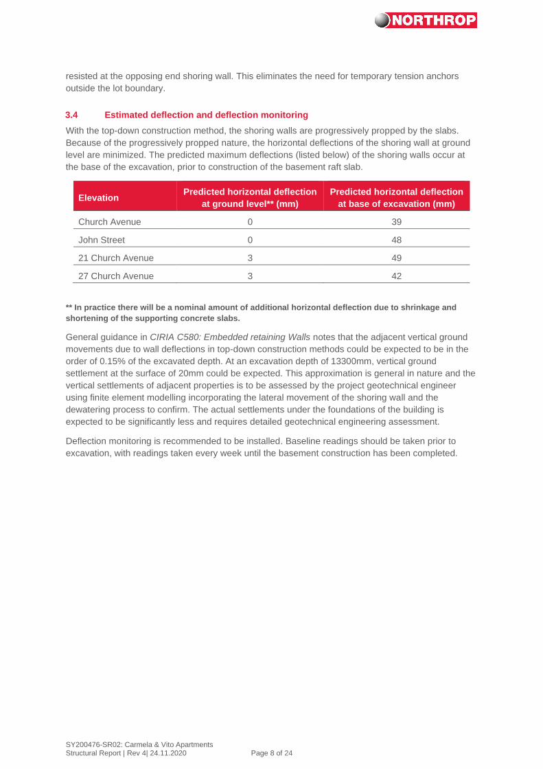
3.4 Estimated deflection and deflection monitoring
With the top-down construction method, the shoring walls are progressively propped by the slabs.
Because of the progressively propped nature, the horizontal deflections of the shoring wall at ground
level are minimized. The predicted maximum deflections (listed below) of the shoring walls occur at
the base of the excavation, prior to construction of the basement raft slab.
Elevation Predicted horizontal deflection
at ground level** (mm)
Predicted horizontal deflection
at base of excavation (mm)
Church Avenue 0 39
John Street 0 48
21 Church Avenue 3 49
27 Church Avenue 3 42
** In practice there will be a nominal amount of additional horizontal deflection due to shrinkage and
shortening of the supporting concrete slabs.
General guidance in CIRIA C580: Embedded retaining Walls notes that the adjacent vertical ground
movements due to wall deflections in top-down construction methods could be expected to be in the
order of 0.15% of the excavated depth. At an excavation depth of 13300mm, vertical ground
settlement at the surface of 20mm could be expected. This approximation is general in nature and the
vertical settlements of adjacent properties is to be assessed by the project geotechnical engineer
using finite element modelling incorporating the lateral movement of the shoring wall and the
dewatering process to confirm. The actual settlements under the foundations of the building is
expected to be significantly less and requires detailed geotechnical engineering assessment.
Deflection monitoring is recommended to be installed. Baseline readings should be taken prior to
excavation, with readings taken every week until the basement construction has been completed.

SY200476-SR02: Carmela & Vito Apartments Structural Report | Rev 4| 24.11.2020 Page 9 of 24
4. Construction Sequence
The following outlines the construction sequence to be adopted for constructing the basement. It is
critical that the construction sequence is adhered to, to ensure the wall performance and stability is
achieved.
The top-down construction methodology proposed is:
Stage 1:
• Install 750mm thick CSM shoring wall to property boundaries.
610mm universal beam soldiers are to be embedded in the walls for the full depth at one
metre spacing.
• Install 900 diameter CFA foundation piles from ground level socketed 6000mm into class III
bedrock
A reinforcement cage is to be embedded in the pile extending from base of the pile to finished
level of the base slab.
400WC303 ‘plunge columns’ are to be embedded within the pile extending from base slab to
ground level using appropriate guide system for accurate placement.
• Install temporary columns (as 600 diameter CFA piles) to support temporary penetrations.
These will be removed once basement is completed
Typical Cutter Soil Mix Wall Machine

SY200476-SR02: Carmela & Vito Apartments Structural Report | Rev 4| 24.11.2020 Page 10 of 24
Structural Steel Plunge Column Installation
Indicative Cross-Section at Stage 1

SY200476-SR02: Carmela & Vito Apartments Structural Report | Rev 4| 24.11.2020 Page 11 of 24
Stage 2:
• Shoring and foundation piles/plunge columns completed
Indicative Cross-Section at Stage 2

SY200476-SR02: Carmela & Vito Apartments Structural Report | Rev 4| 24.11.2020 Page 12 of 24
Stage 3:
• Install dewatering wells within site boundary
• Dewater to lower the groundwater level within the property boundary
Note: Use of the cut-off wall socketed into the low permeability bedrock will greatly assist in
controlling the volume of ground water removed, which results in a minimal effect to the
ground water level at adjacent properties. This is discussed further in the Hydrogeological
assessment prepared by CMW Geosciences
Indicative Cross-Section at Stage 3

SY200476-SR02: Carmela & Vito Apartments Structural Report | Rev 4| 24.11.2020 Page 13 of 24
Stage 4:
• Construct ground floor slab with temporary penetration for plant access
Slab to be formed and cast on firm cut ground
Slab tied to shoring wall to provide permanent restraint and minimise deflections at top of wall
during excavation
Note:
Ground floor slab is designed with load rating to safely support plant equipment (trucks,
excavators, etc.) movement and staging areas
Expected plant movement and access path is from John Street through to Church Street
Indicative Cross-Section at Stage 4

SY200476-SR02: Carmela & Vito Apartments Structural Report | Rev 4| 24.11.2020 Page 14 of 24
Stage 5:
• When ground level slab has reached design strength, commence excavation beneath ground
floor slab to Basement 1 level
Excavation equipment to be craned in through access penetration
Due to low head clearances, excavation will typically be carried out by small front end loaders
and bobcats
Spoil will be stockpiled at access penetrations and craned out
Indicative Cross-Section at Stage 5

SY200476-SR02: Carmela & Vito Apartments Structural Report | Rev 4| 24.11.2020 Page 15 of 24
Indicative 3D view showing ground level slab with access penetration
Stage 6:
• Construct basement 1 slab with penetrations in slab for plant access
Indicative Cross-Section at Stage 6

SY200476-SR02: Carmela & Vito Apartments Structural Report | Rev 4| 24.11.2020 Page 16 of 24
Stage 7:
• Excavate beneath basement 1 slab to basement 2 level
• Construct basement 2 slab with penetration in slab for plant access
Indicative Cross-Section at Stage 7
SY200476-SR02: Carmela & Vito Apartments Structural Report | Rev 4| 24.11.2020 Page 17 of 24
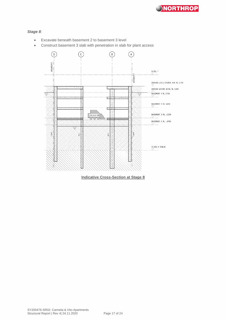
Stage 8:
• Excavate beneath basement 2 to basement 3 level
• Construct basement 3 slab with penetration in slab for plant access
Indicative Cross-Section at Stage 8
SY200476-SR02: Carmela & Vito Apartments Structural Report | Rev 4| 24.11.2020 Page 18 of 24
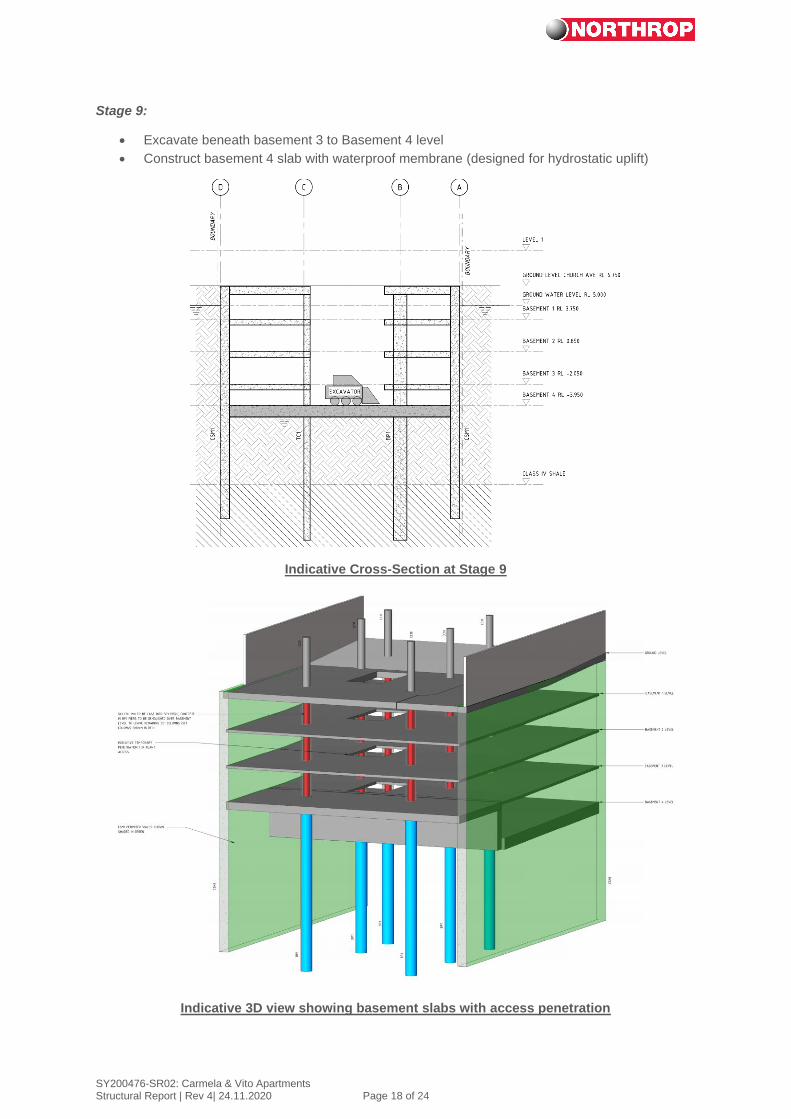
Stage 9:
• Excavate beneath basement 3 to Basement 4 level
• Construct basement 4 slab with waterproof membrane (designed for hydrostatic uplift)
Indicative Cross-Section at Stage 9
Indicative 3D view showing basement slabs with access penetration

SY200476-SR02: Carmela & Vito Apartments Structural Report | Rev 4| 24.11.2020 Page 19 of 24
Stage 10:
• Basement excavation and slabs are completed at stage 10
• Construct core walls from bottom up and remove temporary columns adjacent to core
penetrations
• Cut back CFA piles to expose the structural steel plunge columns
Indicative Cross-Section at Stage 10

SY200476-SR02: Carmela & Vito Apartments Structural Report | Rev 4| 24.11.2020 Page 20 of 24
Stage 11:
• Continue process to reach ground floor
Indicative Cross-Section at Stage 11

SY200476-SR02: Carmela & Vito Apartments Structural Report | Rev 4| 24.11.2020 Page 21 of 24
Stage 12:
• Continue build above ground level conventionally
Indicative Cross-Section at Stage 12

SY200476-SR02: Carmela & Vito Apartments Structural Report | Rev 4| 24.11.2020 Page 22 of 24
Indicative 3D view at completion
SY200476-SR02: Carmela & Vito Apartments Structural Report | Rev 4| 24.11.2020 Page 23 of 24
5. Certification Statement
In our opinion, the proposed development, shoring and basement solution is optimised to reduce risks
associated with constructing a basement for this development. This building will be founded on
bedrock, reducing settlement risks of the adjacent existing buildings significantly. The provision of
cutoff walls into rock minimised the impact of the current water table.
The role of the project geotechnical engineer and hydrogeological consultant in understanding the
project risks and providing expert advice regarding groundwater and related settlements is critical in
developing the proposed basement design. This report must be read in conjunction with advice and
reports by the project Geotechnical Engineer and Hydrogeological Consultant.
Subject to the approval of a professional geotechnical engineer and hydrogeological consultants, we,
Northrop engineers, being professional structural engineers, see no reason why the proposed
basement design and construction methodology should impact the stability of the adjacent buildings.
The recommended mitigation measures must be incorporated into the basement design and form part
of the proposed peer review.
Conclusion
This report has been developed to assist with planning authority approval of the proposed
development. We remain available to assist with any further queries.
Yours sincerely,
Matthew Allen
Associate | Structural Engineer
BE Hons MIEAust CPEng NER
References
CIRIA C580 Embedded Retaining Walls –
Guidance for economic design, London 2003
Todd Halliday
Principal | Structural Engineer
BE(Hons) ME(Stud) MIEAust CPEng NER
Disclaimer: this report has been prepared for Da Vito Ferro Apartments Pty Ltd relating to the
proposed development at 23-25 Church Avenue and 16-18 John Street only and is not to be used by
any other party.
Date Rev Issue Author Verifier
17.08.2020 1 For Review M. Allen T. Halliday
27.08.2020 2 For Review M. Allen T. Halliday
07.09.2020 3 For Review M. Allen T. Halliday
25.11.2020 4 For Review M. Allen T Halliday