structural dynamics of linear elastic single-degree...
TRANSCRIPT

SDOF Dynamics 3 - 1Instructional Material Complementing FEMA 451, Design Examples
Structural Dynamics ofLinear Elastic Single-Degree-of-Freedom
(SDOF) Systems

SDOF Dynamics 3 - 2Instructional Material Complementing FEMA 451, Design Examples
Structural Dynamics
• Equations of motion for SDOF structures
• Structural frequency and period of vibration
• Behavior under dynamic load
• Dynamic magnification and resonance
• Effect of damping on behavior
• Linear elastic response spectra

SDOF Dynamics 3 - 3Instructional Material Complementing FEMA 451, Design Examples
Importance in Relation to ASCE 7-05• Ground motion maps provide ground
accelerations in terms of response spectrumcoordinates.
• Equivalent lateral force procedure gives base shear in terms of design spectrum and period of vibration.
• Response spectrum is based on 5% critical damping in system.
• Modal superposition analysis uses design response spectrum as basic ground motion input.

SDOF Dynamics 3 - 4Instructional Material Complementing FEMA 451, Design Examples
Idealized SDOF Structure
Mass
Stiffness
Damping
F t u t( ), ( )
t
F(t)
t
u(t)

SDOF Dynamics 3 - 5Instructional Material Complementing FEMA 451, Design Examples
F t( )f tI ( )
f tD ( )0 5. ( )f tS0 5. ( )f tS
F t f t f t f tI D S( ) ( ) ( ) ( )− − − = 0
f t f t f t F tI D S( ) ( ) ( ) ( )+ + =
Equation of Dynamic Equilibrium

SDOF Dynamics 3 - 6Instructional Material Complementing FEMA 451, Design Examples
-40
0
40
0.00 0.20 0.40 0.60 0.80 1.00
-0.50
0.00
0.50
0.00 0.20 0.40 0.60 0.80 1.00
-15.00
0.00
15.00
0.00 0.20 0.40 0.60 0.80 1.00
-400.00
0.00
400.00
0.00 0.20 0.40 0.60 0.80 1.00
Acceleration, in/sec2
Velocity, in/sec
Displacement, in
Applied Force, kips
Observed Response of Linear SDOF
Time, sec

SDOF Dynamics 3 - 7Instructional Material Complementing FEMA 451, Design Examples
Observed Response of Linear SDOF(Development of Equilibrium Equation)
-30.00
-15.00
0.00
15.00
30.00
-0.60 -0.30 0.00 0.30 0.60
Displacement, inches
-4.00
-2.00
0.00
2.00
4.00
-20.00 -10.00 0.00 10.00 20.00
Velocity, In/sec
-50.00
-25.00
0.00
25.00
50.00
-500 -250 0 250 500
Acceleration, in/sec2
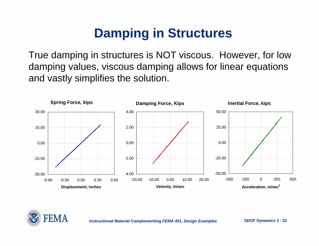
Spring Force, kips Damping Force, Kips Inertial Force, kips
Slope = k= 50 kip/in
Slope = c= 0.254 kip-sec/in
Slope = m= 0.130 kip-sec2/in
f t k u tS ( ) ( )= f t c u tD ( ) &( )= f t m u tI ( ) &&( )=

SDOF Dynamics 3 - 8Instructional Material Complementing FEMA 451, Design Examples
F t( )f tI ( )
f tD ( )0 5. ( )f tS0 5. ( )f tS
m u t c u t k u t F t&&( ) & ( ) ( ) ( )+ + =
Equation of Dynamic Equilibrium
f t f t f t F tI D S( ) ( ) ( ) ( )+ + =

SDOF Dynamics 3 - 9Instructional Material Complementing FEMA 451, Design Examples
Mass
• Includes all dead weight of structure• May include some live load• Has units of force/acceleration
Inte
rnal
For
ce
Acceleration
1.0M
Properties of Structural Mass

SDOF Dynamics 3 - 10Instructional Material Complementing FEMA 451, Design Examples
Damping
• In absence of dampers, is called inherent damping• Usually represented by linear viscous dashpot• Has units of force/velocity
Dam
ping
For
ce
Velocity
1.0C
Properties of Structural Damping

SDOF Dynamics 3 - 11Instructional Material Complementing FEMA 451, Design Examples
Damping
Dam
ping
For
ce
Displacement
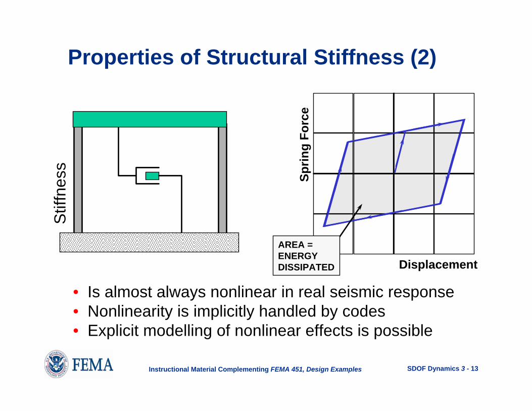
Properties of Structural Damping (2)
Damping vs displacement response iselliptical for linear viscous damper.
AREA =ENERGYDISSIPATED

SDOF Dynamics 3 - 12Instructional Material Complementing FEMA 451, Design Examples
• Includes all structural members• May include some “seismically nonstructural” members• Requires careful mathematical modelling• Has units of force/displacement
Sprin
g Fo
rce
Displacement
1.0K
Properties of Structural StiffnessS
tiffn
ess
SDOF Dynamics 3 - 13Instructional Material Complementing FEMA 451, Design Examples
• Is almost always nonlinear in real seismic response• Nonlinearity is implicitly handled by codes• Explicit modelling of nonlinear effects is possible
Sprin
g Fo
rce
Displacement
Properties of Structural Stiffness (2)S
tiffn
ess
AREA =ENERGYDISSIPATED

SDOF Dynamics 3 - 14Instructional Material Complementing FEMA 451, Design Examples
Undamped Free Vibration
)cos()sin()( 00 tututu ωω
ω+=
&
m u t k u t&&( ) ( )+ = 0Equation of motion:
0u&Initial conditions:
ω0uA&
= B u= 0Solution: ω =km
Assume: u t A t B t( ) sin( ) cos( )= +ω ω
0u

SDOF Dynamics 3 - 15Instructional Material Complementing FEMA 451, Design Examples
ω =km
f =ωπ2
Tf
= =1 2π
ω
Period of Vibration(sec/cycle)
Cyclic Frequency(cycles/sec, Hertz)
Circular Frequency (radians/sec)
Undamped Free Vibration (2)
-3-2-10123
0.0 0.5 1.0 1.5 2.0
Time, seconds
Dis
plac
emen
t, in
ches
T = 0.5 sec
u0
&u01.0

SDOF Dynamics 3 - 16Instructional Material Complementing FEMA 451, Design Examples
Approximate Periods of Vibration(ASCE 7-05)
xnta hCT =
NTa
1.0=
Ct = 0.028, x = 0.8 for steel moment framesCt = 0.016, x = 0.9 for concrete moment framesCt = 0.030, x = 0.75 for eccentrically braced framesCt = 0.020, x = 0.75 for all other systems
Note: This applies ONLY to building structures!
For moment frames < 12 stories in height, minimumstory height of 10 feet. N = number of stories.

SDOF Dynamics 3 - 17Instructional Material Complementing FEMA 451, Design Examples
Empirical Data for Determinationof Approximate Period for Steel Moment Frames
8.0028.0 na hT =

SDOF Dynamics 3 - 18Instructional Material Complementing FEMA 451, Design Examples
Periods of Vibration of Common Structures
20-story moment resisting frame T = 1.9 sec10-story moment resisting frame T = 1.1 sec1-story moment resisting frame T = 0.15 sec
20-story braced frame T = 1.3 sec10-story braced frame T = 0.8 sec1-story braced frame T = 0.1 sec
Gravity dam T = 0.2 secSuspension bridge T = 20 sec

SDOF Dynamics 3 - 19Instructional Material Complementing FEMA 451, Design Examples
SD1 Cu> 0.40g 1.4
0.30g 1.40.20g 1.50.15g 1.6< 0.1g 1.7
computedua TCTT ≤=
Adjustment Factor on Approximate Period(Table 12.8-1 of ASCE 7-05)
Applicable ONLY if Tcomputed comes from a “properlysubstantiated analysis.”

SDOF Dynamics 3 - 20Instructional Material Complementing FEMA 451, Design Examples
If you do not have a “more accurate” period (from a computer analysis), you must use T = Ta.
If you have a more accurate period from a computeranalysis (call this Tc), then:
if Tc > CuTa use T = CuTa
if Ta < Tc < TuCa use T = Tc
if Tc < Ta use T = Ta
Which Period of Vibration to Usein ELF Analysis?

SDOF Dynamics 3 - 21Instructional Material Complementing FEMA 451, Design Examples
Damped Free Vibration
u t e u t u u ttD
DD( ) cos( )
&sin( )= +
+⎡
⎣⎢
⎤
⎦⎥
−ξω ω ξωω
ω00 0
m u t c u t k u t&&( ) &( ) ( )+ + = 0Equation of motion:
u u0 0&Initial conditions:
Solution:
Assume: u t e st( ) =
ξω
= =c
mccc2 ω ω ξD = −1 2

SDOF Dynamics 3 - 22Instructional Material Complementing FEMA 451, Design Examples
ξω
= =c
mccc2
Damping in Structures
cc is the critical damping constant.
Time, sec
Displacement, in
ξ is expressed as a ratio (0.0 < ξ < 1.0) in computations.
Sometimes ξ is expressed as a% (0 < ξ < 100%).
Response of Critically Damped System, ξ=1.0 or 100% critical
SDOF Dynamics 3 - 23Instructional Material Complementing FEMA 451, Design Examples
-30.00
-15.00
0.00
15.00
30.00
-0.60 -0.30 0.00 0.30 0.60
Displacement, inches
-4.00
-2.00
0.00
2.00
4.00
-20.00 -10.00 0.00 10.00 20.00
Velocity, In/sec
-50.00
-25.00
0.00
25.00
50.00
-500 -250 0 250 500
Acceleration, in/sec2
Spring Force, kips Damping Force, Kips Inertial Force, kips
True damping in structures is NOT viscous. However, for lowdamping values, viscous damping allows for linear equations and vastly simplifies the solution.
Damping in Structures

SDOF Dynamics 3 - 24Instructional Material Complementing FEMA 451, Design Examples
Damped Free Vibration (2)
-3-2-10123
0.0 0.5 1.0 1.5 2.0
Time, seconds
Dis
plac
emen
t, in
ches
0% Damping10% Damping20% Damping

SDOF Dynamics 3 - 25Instructional Material Complementing FEMA 451, Design Examples
Damping in Structures (2)Welded steel frame ξ = 0.010Bolted steel frame ξ = 0.020
Uncracked prestressed concrete ξ = 0.015Uncracked reinforced concrete ξ = 0.020Cracked reinforced concrete ξ = 0.035
Glued plywood shear wall ξ = 0.100Nailed plywood shear wall ξ = 0.150
Damaged steel structure ξ = 0.050Damaged concrete structure ξ = 0.075
Structure with added damping ξ = 0.250

SDOF Dynamics 3 - 26Instructional Material Complementing FEMA 451, Design Examples
Inherent damping
Added damping
ξ is a structural (material) propertyindependent of mass and stiffness
critical%0.7to5.0=Inherentξ
ξ is a structural property dependent onmass and stiffness anddamping constant C of device
critical%30to10=Addedξ
Damping in Structures (3)
C

SDOF Dynamics 3 - 27Instructional Material Complementing FEMA 451, Design Examples
ln uu
1
22
21
=−
πξξ
ξπ
≅−u uu
1 2
22
For alldamping values
For very lowdamping values
Measuring Damping from Free Vibration Test
-1
-0.5
0
0.5
1
0.00 0.50 1.00 1.50 2.00 2.50 3.00Time, Seconds
Ampl
itude
u e t0
−ξω
u1
u2 u3

SDOF Dynamics 3 - 28Instructional Material Complementing FEMA 451, Design Examples
Undamped Harmonic Loading
)sin()()( 0 tptuktum ω=+&&Equation of motion:
-150-100
-500
50100150
0.00 0.25 0.50 0.75 1.00 1.25 1.50 1.75 2.00
Time, Seconds
Forc
e, K
ips
po=100 kips= 0.25 sec
= frequency of the forcing function
ωπ2
=T
ω
T

SDOF Dynamics 3 - 29Instructional Material Complementing FEMA 451, Design Examples
Solution:
Particular solution:
Complimentary solution:
u t C t( ) s in ( )= ω
u t A t B t( ) sin( ) cos( )= +ω ω
⎟⎠⎞
⎜⎝⎛ −
−= )sin()sin(
)/(11)( 2
0 ttkptu ω
ωωω
ωω
Undamped Harmonic Loading (2)
m u t k u t p t&&( ) ( ) s in ( )+ = 0 ωEquation of motion:
Assume system is initially at rest:

SDOF Dynamics 3 - 30Instructional Material Complementing FEMA 451, Design Examples
Define β ωω
=
( )u t pk
t t( ) sin( ) sin( )=−
−02
11 β
ω β ω
Static displacementSteady state
response(at loading frequency)
Transient response(at structure’s frequency)
Loading frequency
Structure’s natural frequency
Undamped Harmonic Loading
Dynamic magnifier

SDOF Dynamics 3 - 31Instructional Material Complementing FEMA 451, Design Examples
-10-505
10
0.00 0.25 0.50 0.75 1.00 1.25 1.50 1.75 2.00
-10-505
10
0.00 0.25 0.50 0.75 1.00 1.25 1.50 1.75 2.00
-10-505
10
0.00 0.25 0.50 0.75 1.00 1.25 1.50 1.75 2.00
Time, seconds
spac
ee
t,-200-100
0100200
0.00 0.25 0.50 0.75 1.00 1.25 1.50 1.75 2.00
ω π= 2 rad / secω π= 4 rad / sec uS = 5 0. .inβ = 0 5.
Loading (kips)
Steady stateresponse (in.)
Transientresponse (in.)
Total response(in.)

SDOF Dynamics 3 - 32Instructional Material Complementing FEMA 451, Design Examples
Steady stateresponse (in.)
Transientresponse (in.)
Total response(in.)
Loading (kips)
ω π= 4 rad / secω π≈ 4 rad / sec uS = 5 0. .inβ = 0 99.
-500
-250
0
250
500
0.00 0.25 0.50 0.75 1.00 1.25 1.50 1.75 2.00
-150-100
-500
50100150
0.00 0 .25 0 .50 0 .75 1.00 1 .25 1 .50 1 .75 2 .00
-500
-250
0
250
500
0.00 0.25 0.50 0.75 1.00 1.25 1.50 1.75 2.00
-80
-40
0
40
80
0.00 0.25 0.50 0.75 1.00 1.25 1.50 1.75 2.00Time, seconds
p,

SDOF Dynamics 3 - 33Instructional Material Complementing FEMA 451, Design Examples
-80
-40
0
40
80
0.00 0.25 0.50 0.75 1.00 1.25 1.50 1.75 2.00Time, seconds
Dis
plac
emen
t, in
.
2π uS
Undamped Resonant Response Curve
Linear envelope

SDOF Dynamics 3 - 34Instructional Material Complementing FEMA 451, Design Examples
Steady stateresponse (in.)
Transientresponse (in.)
Total response (in.)
Loading (kips)
ω π= 4 rad / secω π≈ 4 rad / sec uS = 5 0. .inβ = 1 01.
-150-100
-500
50100150
0 .00 0.25 0 .50 0 .75 1 .00 1.25 1 .50 1 .75 2.00
-500
-250
0
250
500
0.00 0.25 0.50 0.75 1.00 1.25 1.50 1.75 2.00
-500
-250
0
250
500
0 .0 0 0 .25 0 .50 0 .75 1 .00 1 .25 1 .50 1 .75 2 .00
-80
-40
0
40
80
0.00 0.25 0.50 0.75 1.00 1.25 1.50 1.75 2.00
T im e, seconds
p,

SDOF Dynamics 3 - 35Instructional Material Complementing FEMA 451, Design Examples
Steady state response (in.)
Transient response (in.)
Total response (in.)
Loading (kips)
ω π=8 rad / secω π= 4 rad / sec uS = 5 0. .inβ = 2 0.
-150-100
-500
50100150
0.00 0.25 0.50 0.75 1.00 1.25 1.50 1.75 2.00
-6
-3
0
3
6
0.00 0.25 0.50 0.75 1.00 1.25 1.50 1.75 2.00
-6
-3
0
3
6
0.00 0.25 0.50 0.75 1.00 1.25 1.50 1.75 2.00
-6
-3
0
3
6
0.00 0.25 0.50 0 .75 1 .00 1 .25 1.50 1.75 2.00
T im e, seconds
p,

SDOF Dynamics 3 - 36Instructional Material Complementing FEMA 451, Design Examples
-12.00
-8.00
-4.00
0.00
4.00
8.00
12.00
0.00 0.50 1.00 1.50 2.00 2.50 3.00
Frequency Ratio β
Mag
nific
atio
n Fa
ctor
1/(1
- β2 ) In phase
180 degrees out of phase
Resonance
Response Ratio: Steady State to Static(Signs Retained)

SDOF Dynamics 3 - 37Instructional Material Complementing FEMA 451, Design Examples
0.00
2.00
4.00
6.00
8.00
10.00
12.00
0.00 0.50 1.00 1.50 2.00 2.50 3.00
Frequency Ratio β
Mag
nific
atio
n Fa
ctor
1/(1
- β2 )
Response Ratio: Steady State to Static(Absolute Values)
Resonance
Slowlyloaded
1.00
Rapidlyloaded

SDOF Dynamics 3 - 38Instructional Material Complementing FEMA 451, Design Examples
Damped Harmonic Loading
m u t cu t k u t p t&&( ) &( ) ( ) sin( )+ + = 0 ωEquation of motion:
-150-100-50
050
100150
0.00 0.25 0.50 0.75 1.00 1.25 1.50 1.75 2.00
Time, Seconds
Forc
e, K
ips
po=100 kips
sec25.02==
ωπT

SDOF Dynamics 3 - 39Instructional Material Complementing FEMA 451, Design Examples
Solution:
Assume system is initially at rest
Particular solution:
Complimentary solution:
u t C t D t( ) sin( ) cos( )= +ω ω
[ ]u t e A t B ttD D( ) sin( ) cos( )= +−ξω ω ω
Damped Harmonic LoadingEquation of motion:
m u t cu t k u t p t&&( ) &( ) ( ) sin( )+ + = 0 ω
ω ω ξD = −1 2
ξω
=c
m2
[ ]u t e A t B ttD D( ) sin( ) cos( )= +− ξω ω ω
+ +C t D tsin( ) cos( )ω ω

SDOF Dynamics 3 - 40Instructional Material Complementing FEMA 451, Design Examples
Transient response at structure’s frequency(eventually damps out)
Steady state response,at loading frequency
D pk
o=−
− +2
1 22 2 2
ξββ ξβ( ) ( )
Damped Harmonic Loading
C pk
o=−
− +1
1 2
2
2 2 2
ββ ξβ( ) ( )
)cos()sin( tDtC ωω +
+[ ]u t e A t B ttD D( ) sin( ) cos( )= +− ξω ω ω

SDOF Dynamics 3 - 41Instructional Material Complementing FEMA 451, Design Examples
-50
-40
-30
-20
-10
0
10
20
30
40
50
0.00 1.00 2.00 3.00 4.00 5.00
Time, Seconds
Dis
plac
emen
t Am
plitu
de, I
nche
sBETA=1 (Resonance)Beta=0.5Beta=2.0
Damped Harmonic Loading (5% Damping)

SDOF Dynamics 3 - 42Instructional Material Complementing FEMA 451, Design Examples
Staticδξ21
-50
-40
-30
-20
-10
0
10
20
30
40
50
0.00 1.00 2.00 3.00 4.00 5.00
Time, Seconds
Dis
plac
emen
t Am
plitu
de, I
nche
sDamped Harmonic Loading (5% Damping)
SDOF Dynamics 3 - 43Instructional Material Complementing FEMA 451, Design Examples
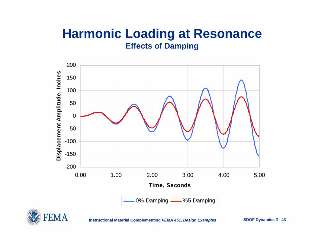
Harmonic Loading at ResonanceEffects of Damping
-200
-150
-100
-50
0
50
100
150
200
0.00 1.00 2.00 3.00 4.00 5.00
Time, Seconds
Dis
plac
emen
t Am
plitu
de, I
nche
s
0% Damping %5 Damping

SDOF Dynamics 3 - 44Instructional Material Complementing FEMA 451, Design Examples
0.00
2.00
4.00
6.00
8.00
10.00
12.00
14.00
0.00 0.50 1.00 1.50 2.00 2.50 3.00
Frequency Ratio, β
Dyn
amic
Res
pons
e A
mpl
ifier
0.0% Damping5.0 % Damping10.0% Damping25.0 % Damping
RD =− +
11 22 2 2( ) ( )β ξβ
Resonance
Slowlyloaded Rapidly
loaded

SDOF Dynamics 3 - 45Instructional Material Complementing FEMA 451, Design Examples
Summary Regarding Viscous Dampingin Harmonically Loaded Systems
• For systems loaded at a frequency near their natural frequency, the dynamic response exceeds the static response. This is referred to as dynamic amplification.
• An undamped system, loaded at resonance, will have an unbounded increase in displacement over time.

SDOF Dynamics 3 - 46Instructional Material Complementing FEMA 451, Design Examples
Summary Regarding Viscous Dampingin Harmonically Loaded Systems
• Damping is an effective means for dissipating energy in the system. Unlike strain energy, which is recoverable, dissipated energy is not recoverable.
• A damped system, loaded at resonance, will have a limited displacement over time with the limit being (1/2ξ) times the static displacement.
• Damping is most effective for systems loaded at or near resonance.

SDOF Dynamics 3 - 47Instructional Material Complementing FEMA 451, Design Examples
LOADING YIELDING
UNLOADING UNLOADED
F F
F
u
F
u
u u
EnergyStored
EnergyDissipated
EnergyRecovered
TotalEnergyDissipated
CONCEPT of ENERGY STOREDand Energy DISSIPATED
12
1
3
2
4
3

SDOF Dynamics 3 - 48Instructional Material Complementing FEMA 451, Design Examples
Time, T
F(t)
General Dynamic Loading

SDOF Dynamics 3 - 49Instructional Material Complementing FEMA 451, Design Examples
General Dynamic Loading Solution Techniques
• Fourier transform
• Duhamel integration
• Piecewise exact
• Newmark techniques
All techniques are carried out numerically.

SDOF Dynamics 3 - 50Instructional Material Complementing FEMA 451, Design Examples
dt
( ) odFF Fdt
τ τ= +
dF
dt
τ
Piecewise Exact Method
Fo

SDOF Dynamics 3 - 51Instructional Material Complementing FEMA 451, Design Examples
Initial conditions 00, =ou 00, =ou&
Determine “exact” solution for 1st time step
)(1 τuu = )(1 τuu && = )(1 τuu &&&& =
)(1, τuuo = )(1,0 τuu && =Establish new initial conditions
Obtain exact solution for next time step
)(2 τuu = )(2 τuu && = )(2 τuu &&&& =
LOOP
Piecewise Exact Method

SDOF Dynamics 3 - 52Instructional Material Complementing FEMA 451, Design Examples
Piecewise Exact Method
Advantages:
• Exact if load increment is linear• Very computationally efficient
Disadvantages:
• Not generally applicable for inelastic behavior
Note: NONLIN uses the piecewise exact method forresponse spectrum calculations.

SDOF Dynamics 3 - 53Instructional Material Complementing FEMA 451, Design Examples
Newmark Techniques
• Proposed by Nathan Newmark• General method that encompasses a family of different
integration schemes• Derived by:
– Development of incremental equations of motion– Assuming acceleration response over short time step

SDOF Dynamics 3 - 54Instructional Material Complementing FEMA 451, Design Examples
Newmark MethodAdvantages:
• Works for inelastic response
Disadvantages:
• Potential numerical error
Note: NONLIN uses the Newmark method forgeneral response history calculations

SDOF Dynamics 3 - 55Instructional Material Complementing FEMA 451, Design Examples
-0.40
-0.20
0.00
0.20
0.40
0.00 1.00 2.00 3.00 4.00 5.00 6.00
TIME, SECONDS
GR
OU
ND
AC
C, g
Development of Effective Earthquake Force

SDOF Dynamics 3 - 56Instructional Material Complementing FEMA 451, Design Examples
Earthquake Ground Motion, 1940 El Centro
Many ground motions now are available via the Internet.
-0.3
-0.2
-0.1
0
0.1
0.2
0.3
0.4
0 10 20 30 40 50 60
Time (sec)
Gro
und
Acce
lera
tion
(g's
)
-30
-20
-10
0
10
20
30
40
0 10 20 30 40 50 60
Time (sec)
Gro
und
Velo
city
(cm
/sec
)
-15
-10
-5
0
5
10
15
0 10 20 30 40 50 60
Time (sec)
Gro
und
Disp
lace
men
t (cm
)

SDOF Dynamics 3 - 57Instructional Material Complementing FEMA 451, Design Examples
m u t u t c u t k u tg r r r[&& ( ) && ( )] & ( ) ( )+ + + = 0
mu t c u t k u t mu tr r r g&& ( ) & ( ) ( ) && ( )+ + = −
Development of Effective Earthquake Force
-0.40
-0.20
0.00
0.20
0.40
0.00 1.00 2.00 3.00 4.00 5.00 6.00
TIME, SECONDS
GR
OU
ND
AC
C, g
Ground Acceleration Response History
gu&& tu&&ru&&

SDOF Dynamics 3 - 58Instructional Material Complementing FEMA 451, Design Examples
)()()()( tumtuktuctum grrr &&&&& −=++
)()()()( tutumktu
mctu grrr &&&&& −=++
ξω2=mc 2ω=
mk
Divide through by m:
Make substitutions:
“Simplified” form of Equation of Motion:
)()()(2)( 2 tutututu grrr &&&&& −=++ ωξωSimplified form:

SDOF Dynamics 3 - 59Instructional Material Complementing FEMA 451, Design Examples
)()()(2)( 2 tutututu grrr &&&&& −=++ ωξω
Ground motion acceleration history
Structural frequency
Damping ratio
For a given ground motion, the response history ur(t) is function of the structure’s frequency ω and damping ratio ξ.

SDOF Dynamics 3 - 60Instructional Material Complementing FEMA 451, Design Examples
Change in ground motion or structural parameters ξand ω requires re-calculation of structural response
Response to Ground Motion (1940 El Centro)
-6
-4
-2
0
2
4
6
0 10 20 30 40 50 60
Time (sec)
Stru
ctur
al D
ispl
acem
ent (
in)
-0.3
-0.2
-0.1
0
0.1
0.2
0.3
0.4
0 10 20 30 40 50 60
Time (sec)
Gro
und
Acce
lera
tion
(g's)
Excitation applied to structure with given ξ and ω
Peak displacement
Computed response
SOLVER

SDOF Dynamics 3 - 61Instructional Material Complementing FEMA 451, Design Examples
0
4
8
12
16
0 2 4 6 8 10
PERIOD, Seconds
DIS
PLA
CEM
ENT,
inch
es
The Elastic Displacement Response SpectrumAn elastic displacement response spectrum is a plotof the peak computed relative displacement, ur, for anelastic structure with a constant damping ξ, a varyingfundamental frequency ω (or period T = 2π/ ω), respondingto a given ground motion.
5% damped response spectrum for structureresponding to 1940 El Centro ground motion

SDOF Dynamics 3 - 62Instructional Material Complementing FEMA 451, Design Examples
-0.08
-0.06
-0.04
-0.02
0.00
0.02
0.04
0.06
0.08
0 1 2 3 4 5 6 7 8 9 10 11 12
Time, Seconds
Dis
plac
emen
t, In
ches
ξ = 0.05T = 0.10 secUmax= 0.0543 in.
0.00
2.00
4.00
6.00
8.00
10.00
0.00 0.50 1.00 1.50 2.00
Period, Seconds
Dis
plac
emen
t, In
ches
Computation of Response Spectrum for El Centro Ground Motion
Elastic response spectrum
Computed response

SDOF Dynamics 3 - 63Instructional Material Complementing FEMA 451, Design Examples
ξ = 0.05T = 0.20 secUmax = 0.254 in.
-0.40
-0.30
-0.20
-0.10
0.00
0.10
0.20
0.30
0.40
0 1 2 3 4 5 6 7 8 9 10 11 12
Time, Seconds
Dis
plac
emen
t, In
ches
0.00
2.00
4.00
6.00
8.00
10.00
0.00 0.50 1.00 1.50 2.00
Period, Seconds
Dis
plac
emen
t, In
ches
Computation of Response Spectrumfor El Centro Ground Motion
Elastic response spectrum
Computed response

SDOF Dynamics 3 - 64Instructional Material Complementing FEMA 451, Design Examples
ξ = 0.05T = 0.30 secUmax = 0.622 in.
-0.80
-0.60
-0.40
-0.20
0.00
0.20
0.40
0.60
0.80
0 1 2 3 4 5 6 7 8 9 10 11 12
Time, Seconds
Dis
plac
emen
t, In
ches
0.00
2.00
4.00
6.00
8.00
10.00
0.00 0.50 1.00 1.50 2.00
Period, Seconds
Dis
plac
emen
t, In
ches
Computation of Response Spectrumfor El Centro Ground Motion
Elastic response spectrum
Computed response

SDOF Dynamics 3 - 65Instructional Material Complementing FEMA 451, Design Examples
ξ = 0.05T = 0.40 secUmax = 0.956 in.
-1.20
-0.90
-0.60
-0.30
0.00
0.30
0.60
0.90
1.20
0 1 2 3 4 5 6 7 8 9 10 11 12
Time, Seconds
Dis
plac
emen
t, In
ches
0.00
2.00
4.00
6.00
8.00
10.00
0.00 0.50 1.00 1.50 2.00
Period, Seconds
Dis
plac
emen
t, In
ches
Computation of Response Spectrumfor El Centro Ground Motion
Elastic response spectrum
Computed response

SDOF Dynamics 3 - 66Instructional Material Complementing FEMA 451, Design Examples
ξ = 0.05T = 0.50 secUmax = 2.02 in.
-2.40
-1.80
-1.20
-0.60
0.00
0.60
1.20
1.80
2.40
0 1 2 3 4 5 6 7 8 9 10 11 12
Time, Seconds
Dis
plac
emen
t, In
ches
0.00
2.00
4.00
6.00
8.00
10.00
0.00 0.50 1.00 1.50 2.00
Period, Seconds
Dis
plac
emen
t, In
ches
Computation of Response Spectrumfor El Centro Ground Motion
Elastic response spectrum
Computed response

SDOF Dynamics 3 - 67Instructional Material Complementing FEMA 451, Design Examples
ξ = 0.05T = 0.60 secUmax= -3.00 in.
Computation of Response Spectrumfor El Centro Ground Motion
-3.20-2.40-1.60-0.800.000.801.602.403.20
0 1 2 3 4 5 6 7 8 9 10 11 12
Time, Seconds
Dis
plac
emen
t, In
ches
0.00
2.00
4.00
6.00
8.00
10.00
0.00 0.50 1.00 1.50 2.00
Period, Seconds
Dis
plac
emen
t, In
ches
Elastic response spectrum
Computed response

SDOF Dynamics 3 - 68Instructional Material Complementing FEMA 451, Design Examples
Complete 5% Damped Elastic DisplacementResponse Spectrum for El Centro
Ground Motion
0.00
2.00
4.00
6.00
8.00
10.00
12.00
0.0 0.5 1.0 1.5 2.0 2.5 3.0 3.5 4.0Period, Seconds
Dis
plac
emen
t, In
ches

SDOF Dynamics 3 - 69Instructional Material Complementing FEMA 451, Design Examples
Development of PseudovelocityResponse Spectrum
0.00
5.00
10.00
15.00
20.00
25.00
30.00
35.00
0.0 1.0 2.0 3.0 4.0Period, Seconds
Pseu
dove
loci
ty, i
n/se
c
DTPSV ω≡)(
5% damping

SDOF Dynamics 3 - 70Instructional Material Complementing FEMA 451, Design Examples
0.0
50.0
100.0
150.0
200.0
250.0
300.0
350.0
400.0
0.0 1.0 2.0 3.0 4.0Period, Seconds
Pseu
doac
cele
ratio
n, in
/sec
2
DTPSA 2)( ω≡
Development of PseudoaccelerationResponse Spectrum
5% damping

SDOF Dynamics 3 - 71Instructional Material Complementing FEMA 451, Design Examples
The pseudoacceleration response spectrum represents the total acceleration of the system, not the relative acceleration. It is nearly identical to the true total acceleration response spectrum for lightly damped structures.
Note About the Pseudoacceleration Response Spectrum
0.0
50.0
100.0
150.0
200.0
250.0
300.0
350.0
400.0
0.0 1.0 2.0 3.0 4.0Period, Seconds
Pseu
doac
cele
ratio
n, in
/sec
2
5% damping
Peak groundacceleration

SDOF Dynamics 3 - 72Instructional Material Complementing FEMA 451, Design Examples
m u t u t c u t k u tg r r r[&& ( ) && ( )] & ( ) ( )+ + + = 0
mu t c u t k u t mu tr r r g&& ( ) & ( ) ( ) && ( )+ + = −
PSA is TOTAL Acceleration!
-0.40
-0.20
0.00
0.20
0.40
0.00 1.00 2.00 3.00 4.00 5.00 6.00
TIME, SECONDS
GR
OU
ND
AC
C, g
Ground Acceleration Response History
gu&& tu&&ru&&

SDOF Dynamics 3 - 73Instructional Material Complementing FEMA 451, Design Examples
Difference Between Pseudo-Accelerationand Total Acceleration
(System with 5% Damping)
0.00
50.00
100.00
150.00
200.00
250.00
300.00
350.00
0.1 1 10Period (sec)
Acce
lera
tion
(in/s
ec2 )
Total Acceleration Pseudo-Acceleration

SDOF Dynamics 3 - 74Instructional Material Complementing FEMA 451, Design Examples
Difference Between Pseudovelocityand Relative Velocity
(System with 5% Damping)
0
5
10
15
20
25
30
35
40
0.1 1 10Period (sec)
Velo
city
(in/
sec)
Relative Velocity Pseudo-Velocity

SDOF Dynamics 3 - 75Instructional Material Complementing FEMA 451, Design Examples
Displacement Response Spectrafor Different Damping Values
0.00
5.00
10.00
15.00
20.00
25.00
0.0 1.0 2.0 3.0 4.0 5.0Period, Seconds
Dis
plac
emen
t, In
ches
0%5%10%20%
Damping
SDOF Dynamics 3 - 76Instructional Material Complementing FEMA 451, Design Examples
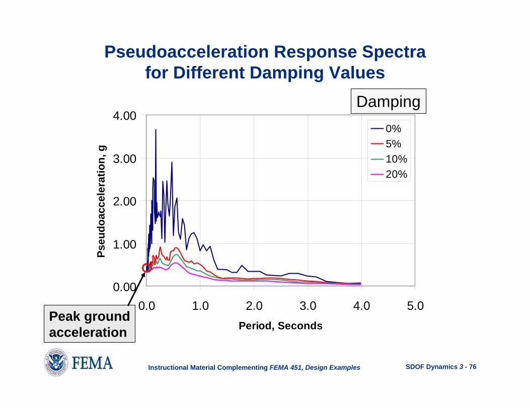
Pseudoacceleration Response Spectrafor Different Damping Values
0.00
1.00
2.00
3.00
4.00
0.0 1.0 2.0 3.0 4.0 5.0Period, Seconds
Pseu
doac
cele
ratio
n, g
0%5%10%20%
Damping
Peak groundacceleration

SDOF Dynamics 3 - 77Instructional Material Complementing FEMA 451, Design Examples
Damping Is Effective in Reducing the Response for (Almost) Any Given Period
of Vibration
• An earthquake record can be considered to be the combination of a large number of harmonic components.
• Any SDOF structure will be in near resonance with oneof these harmonic components.
• Damping is most effective at or near resonance.
• Hence, a response spectrum will show reductions due todamping at all period ranges (except T = 0).

SDOF Dynamics 3 - 78Instructional Material Complementing FEMA 451, Design Examples
Damping Is Effective in Reducing the Response for Any Given Period of
Vibration
Time (sec)
Am
plitu
de
• Example of an artificially generated wave to resemble a real time ground motion accelerogram.
• Generated wave obtained by combining five different harmonic signals, each having equal amplitude of 1.0.
-4.00-2.000.002.004.00
0.0 6.0 12.0 18.0 24.0 30.0 36.0 42.0 48.0 54.0 60.0 66.0 72.0 78.0 84.0 90.0
`

SDOF Dynamics 3 - 79Instructional Material Complementing FEMA 451, Design Examples
The Artificial Wave Is the Sum of Five Harmonics
T = 5.0 s
T = 4.0 s
T = 3.0 s
Time (sec)
Am
plitu
de
-1-0.5
00.5
1
0.0 6.0 12.0 18.0 24.0 30.0 36.0 42.0 48.0 54.0 60.0 66.0 72.0 78.0 84.0 90.0
`
-1-0.5
00.5
1
0.0 6.0 12.0 18.0 24.0 30.0 36.0 42.0 48.0 54.0 60.0 66.0 72.0 78.0 84.0 90.0
`
-1-0.5
00.5
1
0.0 6.0 12.0 18.0 24.0 30.0 36.0 42.0 48.0 54.0 60.0 66.0 72.0 78.0 84.0 90.0
`

SDOF Dynamics 3 - 80Instructional Material Complementing FEMA 451, Design Examples
T = 2.0 s
T = 1.0 s
Time (sec)
Am
plitu
de
Summation
-1-0.5
00.5
1
0.0 6.0 12.0 18.0 24.0 30.0 36.0 42.0 48.0 54.0 60.0 66.0 72.0 78.0 84.0 90.0
`
-1-0.5
00.5
1
0.0 6.0 12.0 18.0 24.0 30.0 36.0 42.0 48.0 54.0 60.0 66.0 72.0 78.0 84.0 90.0
`
-4.00-2.000.002.004.00
0.0 6.0 12.0 18.0 24.0 30.0 36.0 42.0 48.0 54.0 60.0 66.0 72.0 78.0 84.0 90.0
`
The Artificial Wave Is the Sum of Five Harmonics

SDOF Dynamics 3 - 81Instructional Material Complementing FEMA 451, Design Examples
FFT curve for the combined wave
Frequency (Hz)
Four
ier a
mpl
itude
0.00
2.00
4.00
6.00
8.00
10.00
12.00
14.00
0.00 0.50 1.00 1.50 2.00 2.50 3.00
Frequency Ratio, β
Dyn
amic
Res
pons
e A
mpl
ifier
0.0% Damping5.0 % Damping10.0% Damping25.0 % Damping
Damping Reduces the Responseat Each Resonant Frequency

SDOF Dynamics 3 - 82Instructional Material Complementing FEMA 451, Design Examples
Use of an Elastic Response SpectrumExample StructureK = 500 k/inW = 2,000 kM = 2000/386.4 = 5.18 k-sec2/inω = (K/M)0.5 =9.82 rad/secT = 2π/ω = 0.64 sec5% critical damping
0.00
2.00
4.00
6.00
8.00
10.00
12.00
0.0 0.5 1.0 1.5 2.0 2.5 3.0 3.5 4.0
Period, Seconds
Dis
plac
emen
t, In
ches
At T = 0.64 sec, displacement = 3.03 in.

SDOF Dynamics 3 - 83Instructional Material Complementing FEMA 451, Design Examples
Use of an Elastic Response SpectrumExample StructureK = 500 k/inW = 2,000 kM = 2000/386.4 = 5.18 k-sec2/inω = (K/M)0.5 =9.82 rad/secT = 2π/ω = 0.64 sec5% critical damping
At T = 0.64 sec, pseudoacceleration = 301 in./sec2
0.0
50.0
100.0
150.0
200.0
250.0
300.0
350.0
400.0
0.0 0.5 1.0 1.5 2.0 2.5 3.0 3.5 4.0
Period, Seconds
Pseu
doac
cele
ratio
n, in
/sec
2
Base shear = M x PSA = 5.18(301) = 1559 kips

SDOF Dynamics 3 - 84Instructional Material Complementing FEMA 451, Design Examples
Response Spectrum, ADRS Space
0.00
0.20
0.40
0.60
0.80
1.00
0.00 2.00 4.00 6.00 8.00 10.00 12.00
Displacement, inches
Pseu
doac
cele
ratio
n, g
Diagonal lines representperiod values, T
T = 0.64s

SDOF Dynamics 3 - 85Instructional Material Complementing FEMA 451, Design Examples
0.1
1
10
100
0.1 1 10 100 1000
Circular Frequency ω, Radiand per Second
PSEU
DO
VELO
CIT
Y, in
/sec
1.0
D=10.0
0.01
.01
0.1
0.1 0.001
1.0
Line of increasingdisplacement
Line of constantdisplacement
Four-Way Log Plot of Response Spectrum
ωPSVD =
Circular Frequency ω(radians/sec)

SDOF Dynamics 3 - 86Instructional Material Complementing FEMA 451, Design Examples
0.1
1
10
100
0.1 1 10 100 1000
Circular Frequency ω, Radiand per Second
PSEU
DO
VELO
CIT
Y, in
/sec
100
PSA=1000
10000
100
100000
10 1000
10000Line of increasingacceleration
Line of constantacceleration
Four-Way Log Plot of Response Spectrum
PSA PSV= ω
Circular Frequency ω(radians/sec)

SDOF Dynamics 3 - 87Instructional Material Complementing FEMA 451, Design Examples
0.1
1
10
100
0.1 1 10 100 1000
Circular Frequency ω, Radiand per Second
PSEU
DO
VELO
CIT
Y, in
/sec
Four-Way Log Plot of Response Spectrum
10000
1000
100
10
10.1
ACCELERATIO
N, in/se
c2
100
10
1.0
0.1
0.01
0.001
DISPLACEMENT, in
Circular Frequency ω(radians/sec)

SDOF Dynamics 3 - 88Instructional Material Complementing FEMA 451, Design Examples
0.10
1.00
10.00
100.00
0.01 0.10 1.00 10.00
PERIOD, Seconds
PSEU
DO
VELO
CIT
Y, in
/sec
1.0
10.0
0.1
0.01
Acceleration, g
0.001
10.0
0.101.0
0.01
0.001
Displac
emen
t, in.
Four-Way Log Plot of Response SpectrumPlotted vs Period

SDOF Dynamics 3 - 89Instructional Material Complementing FEMA 451, Design Examples
Development of an ElasticResponse Spectrum
0.10
1.00
10.00
100.00
0.01 0.10 1.00 10.00
PERIOD, Seconds
PSEU
DO
VELO
CIT
Y, in
/sec
1.0
10.0
0.1
0.01
Acceleration, g
0.001
10.0
0.10
1.0
0.01
0.001
Displac
emen
t, in.
Problems with Current Spectrum:
It is for a single earthquake; otherearthquakes will have differentCharacteristics.
For a given earthquake,small variations in structural frequency (period) can producesignificantly different results.

SDOF Dynamics 3 - 90Instructional Material Complementing FEMA 451, Design Examples
0.1
1
10
100
0.01 0.1 1 10Period, Seconds
Pseu
do V
eloc
ity, I
n/Se
c
0% Damping5% Damping10% Damping20* Damping
1.0
10.0
0.1
0.01
Acceleration, g
0.001
10.0
0.10
1.0
0.01
0.001
Displac
emen
t, in.
For a given earthquake,small variations in structural frequency (period) can producesignificantly different results.
1940 El Centro, 0.35 g, N-S

SDOF Dynamics 3 - 91Instructional Material Complementing FEMA 451, Design Examples
0.1
1.0
10.0
100.0
0.01 0.10 1.00 10.00Period, seconds
Pseu
so V
eloc
ity, i
n/se
c
El CentroLoma PrietaNorth RidgeSan FernandoAverage
5% Damped Spectra for Four California EarthquakesScaled to 0.40 g (PGA)
Different earthquakeswill have different spectra.

SDOF Dynamics 3 - 92Instructional Material Complementing FEMA 451, Design Examples
Smoothed Elastic Response Spectra(Elastic DESIGN Response Spectra)
• Newmark-Hall spectrum
• ASCE 7 spectrum

SDOF Dynamics 3 - 93Instructional Material Complementing FEMA 451, Design Examples
0.1
1
10
100
0.01 0.1 1 10 100Period (sec)
Disp
lace
men
t (in
)
0% Damping5% Damping10% Damping
Newmark-Hall Elastic Spectrum
Observations
gu&&max
gu&max
gumax
gvv &&&& max→
gvv max→
at short T
at long T
0→v
0→v&&

SDOF Dynamics 3 - 94Instructional Material Complementing FEMA 451, Design Examples
Very Stiff Structure (T < 0.01 sec)
Total accelerationZero
Ground accelerationRelative displacement

SDOF Dynamics 3 - 95Instructional Material Complementing FEMA 451, Design Examples
Very Flexible Structure (T > 10 sec)
Relative displacement Total acceleration
Ground displacement Zero

SDOF Dynamics 3 - 96Instructional Material Complementing FEMA 451, Design Examples
0.1
1
10
100
0.01 0.1 1 10Period, Seconds
Pseu
do V
eloc
ity, I
n/Se
c
0% Damping5% Damping10% Damping20* Damping
1.0
10.0
0.1
0.01
Acceleration, g
0.001
10.0
0.10
1.0
0.01
0.001
Displac
emen
t, in.
1940 El Centro, 0.35 g, N-S
0.35g
12.7 in/s
4.25 in.
Ground Maxima

SDOF Dynamics 3 - 97Instructional Material Complementing FEMA 451, Design Examples
Damping One Sigma (84.1%) Median (50%)% Critical aa av ad aa av ad
.05 5.10 3.84 3.04 3.68 2.59 2.011 4.38 3.38 2.73 3.21 2.31 1.822 3.66 2.92 2.42 2.74 2.03 1.633 3.24 2.64 2.24 2.46 1.86 1.525 2.71 2.30 2.01 2.12 1.65 1.397 2.36 2.08 1.85 1.89 1.51 1.2910 1.99 1.84 1.69 1.64 1.37 1.2020 1.26 1.37 1.38 1.17 1.08 1.01
Newmark’s Spectrum Amplification Factorsfor Horizontal Elastic Response
SDOF Dynamics 3 - 98Instructional Material Complementing FEMA 451, Design Examples
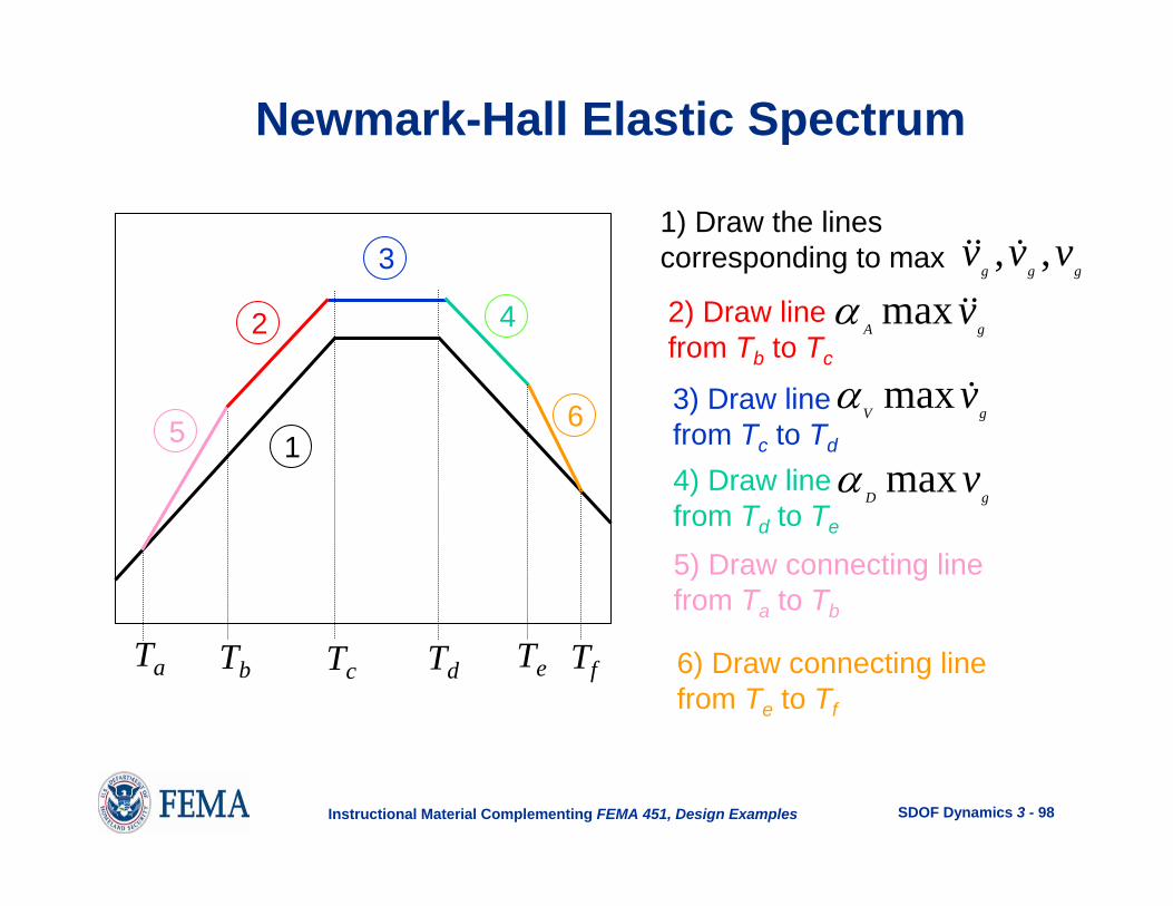
Newmark-Hall Elastic Spectrum
1
3
2 4
65
1) Draw the lines corresponding to max ggg
vvv ,, &&&
2) Draw line from Tb to Tc
Ta Tb Tc Td Te Tf
gAv&&maxα
3) Draw line from Tc to Td
gVv&maxα
4) Draw line from Td to Te
gDvmaxα
5) Draw connecting line from Ta to Tb
6) Draw connecting line from Te to Tf
SDOF Dynamics 3 - 99Instructional Material Complementing FEMA 451, Design Examples
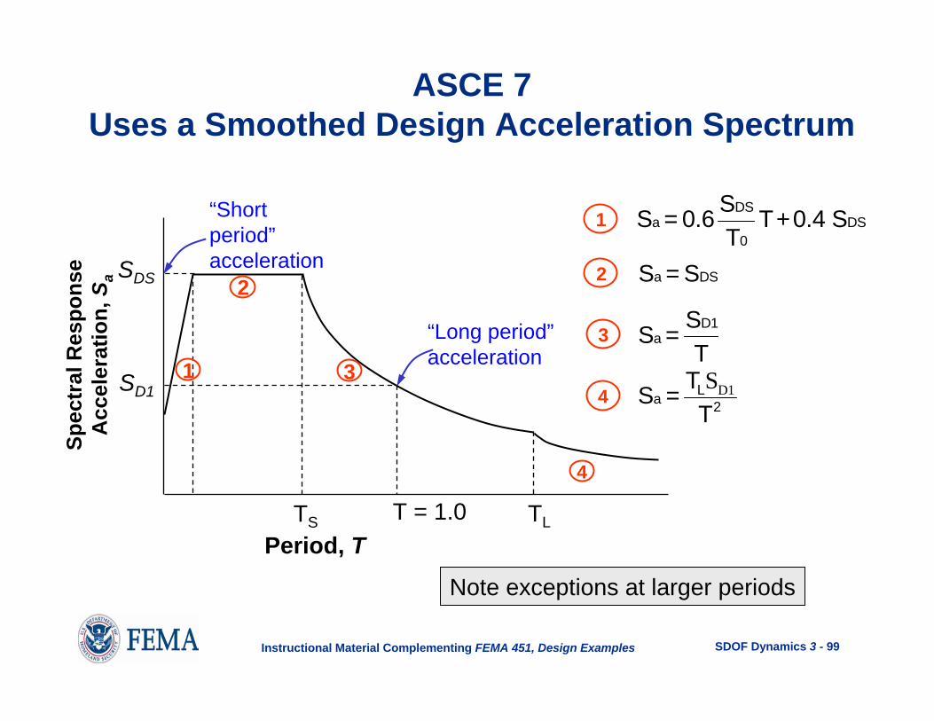
ASCE 7Uses a Smoothed Design Acceleration Spectrum
“Long period”acceleration
TS T = 1.0Period, T
Spec
tral
Res
pons
e A
ccel
erat
ion,
Sa SDS
SD13
2
1
“Short period”acceleration
1
3
2
S = 0.6 ST
T+0.4 SaDS
0DS
S = Sa DS
S = ST
aD1
Note exceptions at larger periods
TL
4 D1SLa 2TS =T
4

SDOF Dynamics 3 - 100Instructional Material Complementing FEMA 451, Design Examples
The ASCE 7 Response Spectrum
is a uniform hazard spectrum based onprobabilistic and deterministic seismichazard analysis.